

Page 1
GE
g
Lighting Solutions
Industrial Luminaires with Electro-
Mechanical Sliding Optical Disconnect
Installation and Maintenance
VERSABEAM PROTECTED BY
U.S. PATENT NUMBER 5,416,684
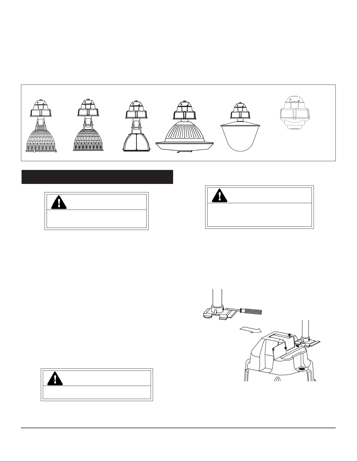
FG5, FG6 DG5, DG6 OG5, OG6 LM5 VS5
MOUNTING
READ THOROUGHLY BEFORE INSTALLING
Save instructions for future use.
Conduit Mounting:
GEH-5864C
INSTRUCTIONS
FG6
LARGE BALLAST HOUSING FOR
SOME OPTIONS
(See GE Lighting Systems Product
Catalog for details)
WARNING
Risk of electric shock
• Turn power off before servicing
– see instructions
NOTE: Maximum fixture ambient temperature rating is determined by the lesser rating as
indicated on the ballast assembly and the optical assembly.
GENERAL
This luminaire is designed for indoor (check label for damp or wet location suitability) applications, and
should be installed and maintained according to following recommendations. It consists of two assemblies, ballast and optical, which may be shipped separately.
Any part damaged or broken during or after assembly should be replaced.
If the luminaire you ordered has a polycarbonate or acrylic refractor, please pay particular attention
to the following statement:
All polycarbonates, acrylics and articles made from polycarbonates or acrylics will yellow with time.
The rate of yellowing is determined by the specific material, any additives and coatings, as well as the
optical temperature and exposure to ultraviolet (UV) light.
This yellowing can reduce the light output and impact resistance of products made from polycarbonates or acrylics. In no case should the maximum wattage recommendations listed for the luminaire be
exceeded. Contact factory for more information.
UNPACKING
This luminaire has been properly packed so that no parts should have been damaged during transit.
Inspect to confirm.
No damaged parts should be installed.
NOTE: The luminaire is supplied with a mounting plate or a hanger hub and locking nut which are
threaded together, which is included in carton with the ballast housing.
INSTALLATION
WARNING
Risk of fire
• Keep combustible materials away from lens
– see instructions
• Use lamps specified on nameplate
1. Fasten mounting plate (minimum of five full turns) to 3/4-inch conduit by threading the mounting plate
onto conduit. (Figure 1)
2. Tighten set screw to lock mounting plate to conduit.
3. Loosen set screw on the top corner of the ballast housing.
4. Loosen wiring box door screws on the ballast housing to allow the wiring box door to pivot.
5. Pivot the wiring box door 180 degrees to allow the mounting plate room to slide onto the ballast
housing.
6. Slide mounting plate onto ballast housing, making sure that the upper rim of the ballast housing slides
into the rails of the mounting plate. (Figure 2)
7. Tighten the set screw on the top corner of the ballast housing so that the mounting plate cannot back
out.
8. After wiring is complete, pivot the wiring box door back into the original position and tighten the two
wiring box door screws.
Figure 1
CAUTION
Unit will fall if not installed properly
• Follow installation instructions
NOTE: Minimum clearance of 3 feet must be maintained below luminaire.
These instructions do not purport to cover all details or variations in equipment nor to provide for every possible contingency to be met in connection with installation, operation or
maintenance. Should further information be desired or should particular problems arise which are not covered sufficiently for the purchaser’s purposes, the matter should be referred
to GE Lighting Solutions.
Flexible Mounting: If flexible mounting accessories (hook or loop) are supplied separately, thread
shaft into mounting plate and follow instructions above for conduit mounting.
CAUTION: If this instruction is not followed damage to the mounting parts can occur causing the
fixture to fall. When using hook or loop fixture mounting, do not apply luminaire weight when the
mating parts are as shown in Fig. A. Do not apply any twisting action to the hook and loop assembly.
When properly installed the hook and loop assembly is shown in Fig. B.
Figure 2
Page 2
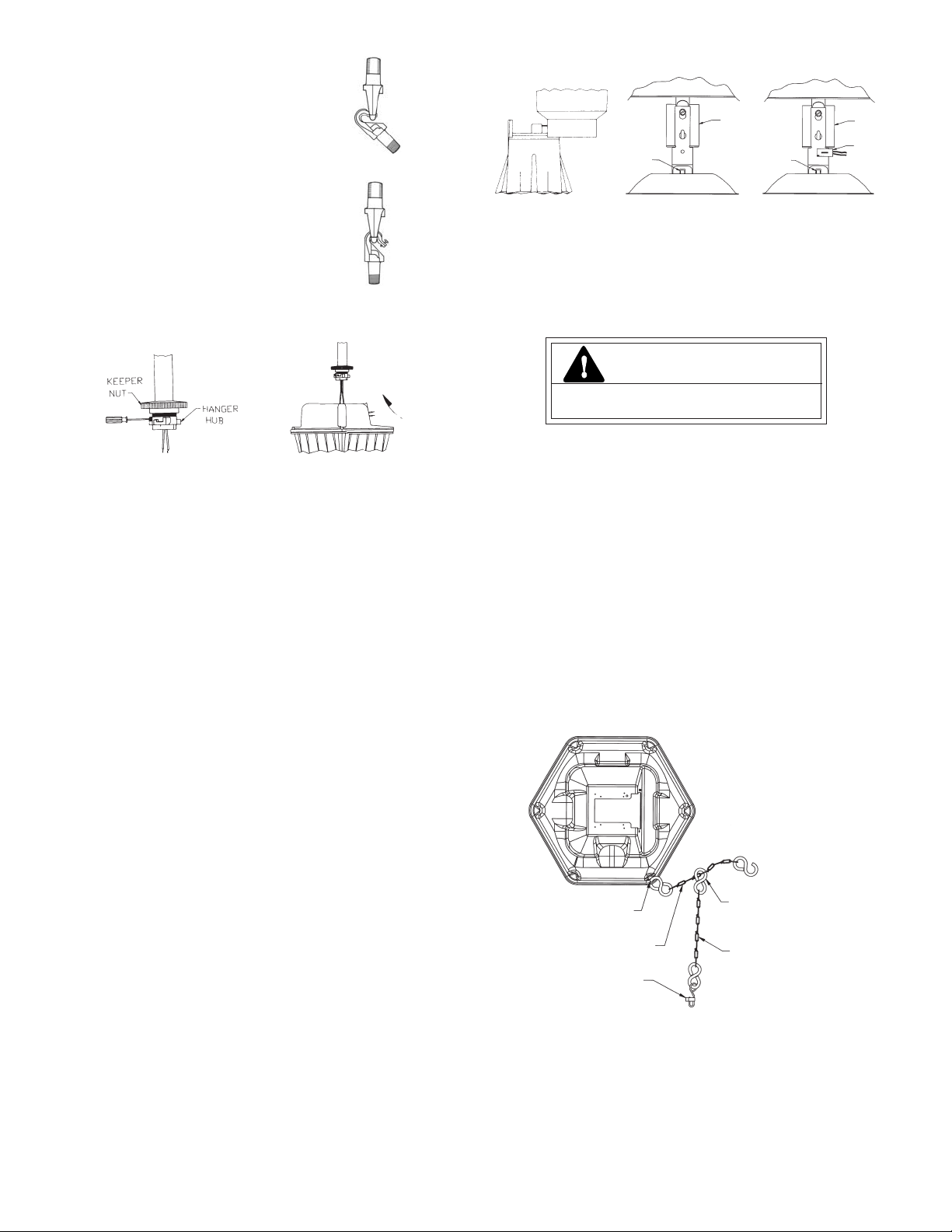
Additional Instructions for Wet Location option (provide
water tight seal between conduit and hanger hub)
1. Fasten hanger hub securely (minimum of five full turns) to
3/4-inch conduit by threading locking nut and hanger hub
assembly onto conduit. (Figure 3)
2. Orient any one of arrows on bottom of hanger hub in
direction that you wish a flat side of ballast housing to
face.
3. Tighten set screw to lock hanger hub to conduit.
4. Loosen locking nut until free to move up conduit.
5. Twist supply leads. Slip ballast housing onto hanger hub
and position housing approximately
30 degrees counter-clockwise from final desired position.
6. Rotate housing clockwise until seated on hanger hub with
wiring box facing in desired direction.
NOTE: Check for proper seating by trying to rotate assembly counter-clockwise while it is supported by the
hanger hub.
7. Hand tighten locking nut against ballast housing. When
installing units provided with a gasket between hangerhub and locking nut, be sure to tighten nut securely so
that gasket is compressed fully around pipe nipple to
prevent entrance of moisture.
Schéma A
Schéma B
2. Refer to LAMP INSTALLATION and screw lamp into socket.
Locking
Tabs
Socket
Locking
Tabs
Socket
Quartz
Socket
Figure 4 Figure 5 Figure 6
NOTE: In case of unit LM5, lamp installation is accomplished through access door in lens by using a
relamp stick.
3. (For enclosed units only) Close door and secure properly in place by latching first latch opposite hinge,
followed by other latches.
NOTE: The OG5 has wing nuts in place of latches.
LAMP INSTALLATION/REPLACEMENT
CAUTION
Risk of burn
• Allow lamp/fixture to cool before handling
Figure 3
WIRING
Make all electrical connections in accordance with the National Electrical Code and any applicable
local code requirements.
Verify that supply voltage is correct by comparing it to nameplate.
If unit is designated as multivolt or multiwatt, follow specific instruction.
Single Voltage Units: Installer needs to connect supply conductors to primary leads and fixture
ground wire. These wires are located on the small wiring harness that contains the 9-pin plug. After these
wires are connected, the 9-pin plug wired in the fixture needs to be mated with the 9-pin plug wired to the
supply conductors (assuming that they are not already connected).
Multi-Volt Units: (Connectable for 120, 208, 240 & 277 volts)
CAUTION: DO NOT REMOVE INSULATED CONNECTORS FROM WIRES NOT NEEDED FOR REQUIRED
VOLTAGE CONNECTION.
Select proper wires from connection diagram on unit. Connect specified wires by utilizing crimp
connectors on wires. These crimp connectors are sized for 14-16 AWG. For other AWG sizes remove crimp
connector(s) provided and use other appropriate approved connector(s).
Multi-Watt Units: See procedure under Multi-Volt above.
NOTE: Attach ground conductor to the green ground wire supplied with the fixture.
9-PIN PLUG REMOVAL: Removal of the 9-pin plug does not hinder the electrical performance of the
luminaire, but its removal does negate the GELS diagnostics meter compatibility.
FINAL ASSEMBLY
LIGHT DISTRIBUTION ADJUSTMENT: FG5, FG6, DG5, DG6,OG5, OG6
The optical assembly is provided with an adjustable socket holder for changing spacing criteria.
Position is preset at factory to meet specified spacing criteria. If it is necessary to adjust socket, consult
photometric tables given in the catalog. Loosen clip screws to allow socket holder to rotate freely. Desired
position is selected by aligning step designation with clips. Rotate clips back to their original position and
retighten screws.
OPTICAL ASSEMBLY/MOUNTING
FG5, FG6, DG5, DG6, LM5, OG5, OG6, VS5
NOTE: Dustproof/weatherproof and severe-duty units are provided with a sponge rubber gasket (in bag
attached to ballast housing) that should be slipped over electrical plug prongs of optical assembly
before final assembly.
1. (Figure 4) Secure reflector to bottom of ballast housing. Installation is aided by key hole slots in
reflector. On VS5 units with safety chains, orient the reflector so that the ballast and reflector holes
are on the same side.
1a. On VS5 units push the reflector mounting bracket thru the reflector opening and slide it over the socket
brackets all the way. On 400 watt Metal Halide units the top (first) hole of the mounting bracket will
snap over the socket bracket screws. On all others, the bottom (second) hole will snap over the
bracket screws. (Figure 5) For additional assembly instructions, refer to the instruction sheet that
came in the small box with the metal reflector and mounting bracket.
NOTE: If VS5 unit has a safety light option, clip quartz socket over socket bracket leg and reflector
bracket leg in a horizontal position (see Figure 6).
The light output of a luminaire is dependent on the age of the lamp. In applications where light level
is critical it may be desirable to replace lamps before they burn out. Lamp manufacturer can provide data
showing how lamp light output decreases with use.
Use only lamps specified on nameplate. Observe lamp manufacturer’s recommendations and
restrictions on lamp operation, particularly ballast type, burning position, etc.
BODY TIGHTNESS: The lamp should be securely inserted and tightened to NEMA-EEI specified torque
of 35 inch-pounds, which is best achieved by firmly tightening to insure application of sufficient torque.
Tightening must be sufficient to fully load and depress the load center contact of socket.
If unit has a SAFETY LIGHT option, insert quartz lamp in its socket making sure to wipe any fingerprints
off lamp.
NOTE: Use of lubricants on lamp bases or sockets can cause rapid lamp failure and voids your fixture
warranty.
SAFETY CHAINS
CAUTION: When used, safety chains must be carefully installed as outlined below.
Safety chains may be attached to luminaire when user feels safety chains should be used. Safety
chains should be attached in a manner to give minimum slack. In no case should a ballast or optical safety
chain be installed in a manner which permits luminaire to fall more than six (6) inches before it is caught
by chain. To install ballast safety chain, insert “S’’ hook through hole in housing and crimp shut. Safety
chains and attachment accessories are available from factory as an optional accessory for both ballast
and optical assemblies.
To install optical safety chain, insert “S” hook through a link in ballast safety chain and crimp shut. Use
snap hook to attach to clip or hole on optical. See figure 7.
CRIMP “S” HOOK TO
LINK IN BALLAST
SAFETY CHAIN
OPTICAL SAFETY CHAIN
Figure 7
HOLE IN HOUSING
BALLAST SAFETY CHAIN
ATTACH SNAP HOOK
TO CLIP OR HOLE
ON OPTICAL
MAINTENANCE
It will occasionally be necessary to clean outside of refractor to maintain light level. Frequency of
cleaning will depend on ambient dirt level and minimum light level which is acceptable to user. Lens door
(if enclosed) should be washed in a solution of warm water and any mild, non-abrasive household detergent,
rinsed with clean water and wiped dry. Should optical assembly become dirty on inside, wipe reflector and
clean lens door in above manner, and replace any damaged gasket.
Page 3

GE
g
Lighting Solutions
Luminaires industriels à déconnexion
optique/glissement électro-mécanique
Installation et entretien
VERSABEAM EST PROTÉGÉ PAR LE NUMÉRO
DE BREVET U.S. 5,416,684
FG5, FG6 DG5, DG6 OG5, OG6 LM5 VS5
MONTAGE
À LIRE TOTALEMENT AVANT D'INSTALLERG
Conservez ces instructions pour référence future.
Montage sur conduite :
GEH-5864C
INSTRUCTIONS
FG6
GROS CAISSON DE BALLAST
POUR CERTAINES OPTIONS
(Voir le catalogue produits de GE
Lighting Systems pour les détails)
DANGER
Risque d’électrocution
• Mettre hors tension avant d’intervenir
– Suivez les instructions
NOTE : La température nominale maximale pour l’appareil est déterminée par la plus basse des
deux supportées respectivement par ses ensembles de ballast et d’optique.
PRÉSENTATION
Ce luminaire est conçu pour les applications en intérieur (vérifiez l’étiquette pour l’adéquation aux
endroits mouillés ou humides), et doit être installé et entretenu en suivant les recommandations qui
suivent. Il est constitué des deux ensembles, ballast et optique, qui peuvent être expédiés séparément.
Toute pièce endommagée ou cassée pendant ou après l’assemblage doit être remplacée.
Si le luminaire que vous avez commandé comporte un réfracteur en polycarbonate, veuillez prêter une
attention particulière à la communication suivante :
Tous les polycarbonates et articles faits avec cette matière, y compris la résine de polycarbonate,
jaunissent dans le temps. La vitesse de jaunissement est fonction du matériau spécifique, des éventuels
additifs et revêtements, ainsi que de la température optique et l’exposition aux ultraviolets (UV).
Ce jaunissement peut réduire la sortie lumineuse et influer sur la résistance aux chocs des produits
à base de résine de polycarbonate. Il ne faut en aucun cas dépasser l’indication de tension secteur nominale
de ce luminaire. Veuillez contacter l’usine si vous souhaitez plus d’informations.
DÉBALLAGE
Ce luminaire a été soigneusement emballé de sorte qu’aucune pièce ne devrait avoir été endommagée
pendant le transport. Effectuez une inspection pour le confirmer.
Aucune pièce endommagée ne doit être installée.
NOTE : Ce luminaire est fourni avec une plaque de montage ou un raccord de suspension et un écrou
de blocage qui sont vissés ensemble, ils sont livrés dans le carton avec le caisson de ballast.
INSTALLATION
DANGER
Risque d’incendie
• Gardez tous matériaux inflammables loin des lentilles
(voir les instructions)
• Utilisez les lampes préconisées
1. Fixez la plaque de montage sur une conduite de 19 mm (3/4”) en la vissant dessus (au moins
cinq tours complets). (Schéma 1)
2. Serrez la vis de blocage pour verrouiller la plaque de montage sur la conduite.
3. Desserrez la vis de fixation sur l’angle supérieur du caisson de ballast.
4. Desserrez les vis de la porte de la boîte de câblage du caisson de ballast pour permettre à
cette porte de pivoter.
5. Faites pivoter la porte de boîte de câblage de 180° afin de laisser à la plaque de montage la
place pour se glisser dans le caisson de ballast.
6. Glissez la plaque de montage dans le caisson de ballast, en vous assurant que le bord supérieur
du caisson s’insère bien dans les rails de la plaque de montage. (Schéma 2)
7. Serrez la vis de fixation sur l’angle supérieur du caisson de ballast pour que la plaque de
montage ne puisse pas se dégager.
8. Une fois le câblage terminé, faites pivoter la porte de boîte de câblage pour la refermer en
position originelle et resserrez ses deux vis.
Schéma 1
ATTENTION
Risque de chute en cas de mauvais montage -
Suivez les instructions
NOTE : Un espacement de 1 mètre (3 pieds) au minimum doit être gardé en dessous du
luminaire.
Ces instructions n'ont pas pour destination de couvrir tous les détails ou variantes de l'équipement, ni de répondre à toutes les éventualités que vous pourriez rencontrer pendant l'installation,
le fonctionnement ou l'entretien. Si vous souhaitez des informations complémentaires, ou si vous rencontrez un problème particulier qui ne soit pas adressé de votre point de vue d'acheteur,
le sujet doit être remonté jusqu'à la société GE Lighting Solutions
Montage flexible : Si les accessoires de montage flexible (crochet ou boucle) sont livrés
séparément, vissez leur axe dans la plaque de montage et suivez les instructions ci-dessus relatives au montage sur conduite.
ATTENTION : Par non respect des instructions, les dommages aux pièces de montage peuvent
causer la chute du luminaire. Avec les accessoires de montage à crochet ou boucle, n’appliquez
pas le poids du luminaire si les pièces de suspension sont en position comme au schéma A. Ne
tordez pas l’assemblage à crochet ou à boucle. Une installation correcte est illustrée au
schéma B.
Schéma 2
Page 4

Instructions supplémentaires pour l’option emplacements humides
(fournit une étanchéité à l’eau entre la conduite et l’embase de suspension)
1. Serrez solidement le raccord de suspension (au moins cinq tours
complets) sur la conduite de 19 mm (3/4”) en vissant dessus
l’assemblage d’écrou de blocage et de raccord de suspension.
(Schéma 3)
2. Orientez une des flèches au bas du raccord de suspension dans la
direction à laquelle vous voulez que la boîte de câblage fasse face.
3. Serrez la vis de blocage pour fixer le raccord de suspension sur la
conduite.
4. Desserrez l’écrou freiné jusqu’à ce qu’il soit libre pour monter sur
la conduite.
5. Tressez les fils d’alimentation. Introduisez le caisson de ballast
dans le support de suspension et positionnez-le à environ 30° avant
(sens inverse des aiguilles d’une montre) sa position finale désirée.
6. Faitez tourner dans le sens du vissage le caisson jusqu’à ce qu’il
se cale dans le raccord de suspension avec sa boîte de
raccordement en face de la direction d’accès voulue.
NOTE : Vérifiez le bon positionnement en tournant l’ensemble dans le
sens du dévissage pendant qu’il est supporté par le raccord de
suspension.
7. Serrez à la main l’écrou freiné contre le caisson de ballast. Sur les
modèles avec un joint entre le raccord de suspension et l’écrou,
prenez soin de serrer assez pour que le joint statique soit bien
compressé autour du rebord de tuyau pour empêcher l’entrée
d’humidité.
Schéma A
Schéma B
Schéma 3
ÉCROU
FREINÉ
CÂBLAGE
Établissez toutes les liaisons électriques en conformité avec les normes nationales ou vos
réglementations locales en vigueur.
Vérifiez que la tension secteur disponible est compatible avec celle de l’appareil indiquée sur sa plaque
d’identification.
Si l’appareil est conçu pour être multi-tensions ou multi-puissances, suivez les instructions spécifiques.
Modèles mono-tension : L’installateur doit relier l’arrivée d’alimentation sur les fils primaires et le fil
de terre du luminaire. Ces fils sont situés dans le petit câble qui comporte la prise 9 broches. Une fois ces
fils reliés la prise 9 broches du luminaire doit être (si ce n’est pas déjà fait) embrochée dans la prise 9
broches câblée aux arrivées d’alimentation.
Modèles multi-tensions : (Branchables sur 120, 208, 240 & 277 volts)
ATTENTION : N'ENLEVEZ PAS LES COSSES ISOLÉES DES FILS NON CONCERNÉS PAR LE RACCORDEMENT
DE LA TENSION.
Sélectionnez les bons fils en fonction du schéma de câblage sur le luminaire. Connectez ce ou ces fils
spécifiés en les munissant de cosses à sertir fournies, qui sont prévues pour accepter des tailles de fil de
14-16 AWG. Dans le cas d’autres tailles AWG de fils, écartez les cosses fournies et utilisez-en une ou
plusieurs autres de la taille voulue.
Modèles multi-puissances : Reportez-vous à la procédure multi-tensions ci-dessus.
NOTE : Reliez le conducteur de terre au fil de terre vert fourni avec le luminaire.
SUPRESSION DE LA PRISE 9 BROCHES : Enlever cette prise ne modifie pas la performance électrique
du luminaire, mais supprime la compatibilité future avec l’appareil GELS de mesure et diagnostics.
RACCORD DE
SUSPENSION
ASSEMBLAGE FINAL
RÉGLAGE DE DISTRIBUTION LUMINEUSE—FG5, FG6, DG5, DG6, OG5, OG6
L’ensemble optique est livré avec un support de douille réglable pour modifier les critères d’écartement.
Sa position est prédéterminée en usine pour répondre aux spécifications. S’il est nécessaire de régler ce
support, consultez les tables photomètriques fournies dans le catalogue. Desserrez les vis d’attache pour
permettre au support de douille de pivoter librement. La position désirée est sélectionnée en alignant la
désignation de l’échelon avec les attaches. Ramenez les attaches en position d’origine et resserrez leurs
vis.
2. Reportez-vous à la section INSTALLATION DE LAMPE et vissez la lampe dans sa douille.
PATTES DE
VERROUILLAGE
DOUILLE
PATTES DE
VERROUILLAGE
DOUILLE
DOUILLE DE
LAMPE AU
QUARTZ
Schéma 4 Schéma 5 Schéma 6
NOTE : Dans le cas du modèle LM5, l’installation de lampe est réalisée par une trappe d’accès dans la
lentille en utilisant une perche pour remplacements.
3. (Pour les modèles encastrés seulement) Fermez la porte et fixez solidement en place, en verrouillant
d’abord l’attache à l’opposé de la charnière, puis les autres attaches.
NOTE : Le modèle OG5 a des écrous papillon à la place des attaches.
INSTALLATION/REPLACEMENT DE LA LAMPE
ATTENTION
Risque de brûlure
• Laissez le bloc d’ampoule refroidir avant d’y toucher
Le niveau d’éclairage d’un luminaire est également fonction de l’âge de sa lampe. Dans les applications
où le niveau lumineux est critique il peut être souhaitable de remplacer les lampes avant d’attendre
qu’elles grillent. Le fabricant de lampes peut fournir des données illustrant comment le niveau lumineux de
la lampe diminue au fur et à mesure de son utilisation.
N'utilisez que des lampes listées sur la plaque. Suivez les recommandations et restrictions de leur
fabricant sur leur fonctionnement, en particulier pour le type de ballast, la position d'utilisation, etc.
SERRAGE DE LAMPE : La lampe doit être insérée de façon sûre avec un couple de serrage NEMA-EEI
spécifié à 4,4 mkg (35 livre-pouce), ce qui est le mieux réalisé en serrant fortement à la main pour mettre
un couple suffisant. Le serrage doit complètement appuyer et charger le contact central de la douille avec
le culot de la lampe.
Si le luminaire a une option SAFETY LIGHT, insérez la lampe à quartz dans sa douille en vous assurant
d’avoir effacé toutes éventuelles traces de doigts sur la lampe.
NOTE : L’utilisation de lubrifiants sur le culot ou la douille de la lampe peut amener rapidement une
panne de lampe et annuler la garantie sur votre appareil.
CHAÎNES DE SÉCURITÉ
ATTENTION : Quand elles sont utilisées, les chaînes de sécurité doivent être soigneusement
montées comme expliqué ci-dessous.
Les chaînes de sécurité doivent être attachées au luminaire quand l’utilisateur estime qu’elles doivent
être utilisées. L’attache doit laisser un mou minimum. Il ne faut jamais installer une chaîne de sécurité
sur un module optique ou un ballast de sorte que le luminaire puisse tomber sur plus de 15 cm (6po) avant
d’être retenu par la chaîne. Pour installer une chaîne de sécurité sur le ballast, insérez le crochet en “ S “
dans le trou du boîtier et serrez la fermeture du S. Des chaînes de sécurité et accessoires d’attache sont
disponibles par l’usine comme un accessoire optionnel à la fois pour les ensembles de ballast et d’optique.
Pour installer une chaîne de sécurité sur le module optique, insérez le crochet en “ S “ dans un maillon de la
chaîne de sécurité du ballast et serrez la fermeture du S. Utilisez un crochet à pression pour fixer à la pince ou au
trou du module optique (voir figure 7).
ASSEMBLAGE/MONTAGE D’OPTIQUE—
FG5, FG6, DG5, DG6, LM5, OG5, OG6, VS5
NOTE : Des luminaires étanches aux poussières et pour une utilisation sous des environnements et
conditions difficiles sont fournis avec un joint en caoutchouc spongieux (dans un sachet attaché au
caisson de ballast) qui doit être enfilé sur les broches de fiches électriques de l’ensemble optique
avant l’assemblage final.
1. (Schéma 4) Fixez le réflecteur sur le dessous du caisson de ballast. L’installation est facilitée par les
ouvertures en trou de serrure du réflecteur. Sur les modèles VS5 avec chaînes de sécurité, orientez le
réflecteur pour que les trous de ballast et réflecteurs soient du même côté.
1a. Dans le cas d'appareils VS5, vous devez pousser le support de montage du réflecteur dans l'ouverture du
réflecteur, puis le faire glisser sur le support de douille, jusqu'au bout. Dans le cas d'appareils Metal Halide
de 400 watts, le trou supérieur (premier trou) du support de montage doit s'emboîter sur les vis du support
de douille. Sur tous les autres appareils, le trou inférieur (deuxième trou) est celui qui s'emboîte sur les vis
du support (voir la figure 5).
Pour plus de détails sur les instructions d'assemblage, consultez la notice se trouvant dans la petite boîte
avec le réflecteur métallique et le support de montage.
EMARQUE : Si vous avez un luminaire VS5 avec LAMPE DE SÉCURITÉ optionnelle, accrochez la douille de lampe
au quartz sur la patte du support de douille et sur la patte du support de réflecteur, en position horizontale
comme dans la figure 6.
GE Lighting Solutions • 1-888-MY-GE-LED • www.gelightingsolutions.com
16943533----888
GE Lighting Solutions is a subsidiary of the General Electric Company. Evolve and other trademarks belong to GE Lighting Solutions. The GE brand and logo are trademarks of the General Electric Company.
© 2011 GE Lighting Solutions. Information provided is subject to change without notice. All values are design or typical values when measured under laboratory conditions.
g
SERREZ LA FERMETURE
DU “ S “ DANS UN MAILLON
DE LA CHAÎNE DE SÉCURITÉ
DU BALLAST
CHAÎNE DE SÉCURITÉ DU
MODULE OPTIQUE
Schéma 7
TROU DANS LE BOÎTIER
CHAÎNE DE SÉCURITÉ DU BALLAST
FIXER UN CROCHET À PRESSION
SUR LA PINCE OU LE TROU DU
MODULE OPTIQUE
ENTRETIEN
Il sera nécessaire à l’occasion de nettoyer l’extérieur du réfracteur pour maintenir le niveau
lumineux. La périodicité de ce nettoyage est fonction de l’empoussièrement ambiant et du seuil
minimum d’éclairage toléré par l’utilisateur. La porte de lentille (si incluse) doit être nettoyée avec
une solution d’eau chaude et de n’importe quel détergent ménager doux et non abrasif, puis rincée à
l’eau claire et séchée par essuyage. Si l’ensemble optique devenait sale à l’intérieur, essuyez le
réflecteur et nettoyez la porte de lentille de la même manière et remplacez tout joint détérioré.
35-201578-2R (10/05)
 Loading...