

Page 1

Trace Moisture Transmitter
DewPro
®
MMY31
Installation and Operation Manual
GE Infrastructure Sensing
GE General Eastern
Page 2

DewPro MMY31
Caution!
Safety
General Notes
Caution!
Before installation please read all instructions.
Safety
- The DewPro is designed to be mounted to pressurized systems. Take necessary
precautions when mounting or removing the DewPro.
GE General Eastern reserves the right to change or modify our product appearance and
specifications at any time and without notice. Therefore, information in this document is
subject to change without notice and does not represent a commitment on the part of GE
General Eastern.
No part of this manual may be reproduced or transmitted in any form or by any
means, electronic or mechanical, including photocopying and recording, for any
purpose without the express written permission of GE General Eastern.
DewPro is a Registered Trademark of GE General Eastern.
If you should have questions regarding the product described in this document, or need
further assistance, please contact your local GE General Eastern Sales Centre
Version: FGE/ 220304/MMY31
Installation and Operation Manual
GE General Eastern
2
Page 3

DewPro MMY31
Installation and Operation Manual
Contents
General Notes 2
1.0 General System Information 4
1.1 Unpacking and Inspection
1.2 Introduction
1.3 Theory of Operation
2.0 Installation Guidelines 6
2.1 Mounting the Probe
3.0 Wiring for Configurations with One 7
3.1 Wiring, General Guidelines
3.2 System Configuration, Various
3.3 Mounting in Normal Environments
3.4 Mounting in Environments with Severe Electrical Noise
3.5 Electrical Connection
3 6 General Wiring Instructions
4.0 Optional Display/User Interface 10
4.1 Installation
4.2 Description of the DewPro MMR 31 Programming Matrix
4.3 Special Functions of the Pushbuttons
4.4 Functions of the Matrix (Refer to Figure 20 or appendix 12
5.0 Troubleshooting 17
5.1 General Problems
6.0 Technical Specifications 18
7.0 Accessories 19
7.1 Available Accessories
8.0 Contact adresses 20
Appendix 21
GE General Eastern
3
Page 4
DewPro MMY31
Installation and Operation Manual
1.0 General System Information
1. 1 Unpacking and Inspection
Upon receipt of the DewPro MMY 31, examine the shipping carton for broken or
open packing, distortion, or any other evidence of mishandling. If inspection
indicates damage to the unit or any of its components, notify the carrier (within 15
days of delivery) and request an inspection.
Move the carton to a clean work area and unpack. The carton you receive should
contain:
• DewPro MMY 31
• Installation and Operation Manual
Compare the model number (on the product label) with product structure (see
below) to ensure you have received everything you ordered.
GENERAL EASTERN
MODEL:
SERIAL NO:
SUPPLY:
RANGE:
P max: 500 PSIG
Product Structure MMY31
Certification/Approvals:
R Standard (not certified)
Other
Y
Process Connection
1 3" diameter galvanized floor flange with 12,7 mm (1/2” MNPT)
compression fitting
8
3 1/2" M NPT compression fitting
6 No mounting hardware
G 1/2 compression fitting (Male thread), gasket, SS ferrule
9 Other
Protective Cap:
A
Standard with 100 micron sintered filter
B Without 100 u filter
Enclosure Conduit:
1
1/2" FNPT with cable gland and plug
2 PG 16 (Female) with cable gland and plug
Output Configuration/Dewpoint Range:
A
Output 4-20 mA -90 … +10
status 22 mA
B Output 4-20 mA -90 … +10
status Hold
C Output 4-20 mA -90 … +10
fault status 3,6 mA
D
G
Output 0 … 100 ppm-v, 1 bar, no displ, error 22 mA
E Output 0 … 100 ppm-v, 1 bar, no displ, error Hold
F Output 0 … 100 ppm-v, 1 bar, no displ, error 3,6 mA
With integral display, user interface; free programmable
R 6 A 1 B
The Humidity Experts
MMY31-R 6 A 2 B
10124
9...32 VDC
o
C dewpoint, no display, fault
o
C dewpoint, no display, fault
o
C dewpoint, no display,
Unpacking
Fig. 1
Check Model
Number
GE General Eastern
4
Page 5

DewPro MMY31
Installation and Operation Manual
1.2 Introduction
Unit description
The DewPro MMY 31 is a loop powered dew point transmitter for the trace moisture
range. The transmitter includes an aluminum oxide planar sensor element, a stainless
steel probe, a weather proof enclosure, and microprocessor electronics. It is designed to
be installed “in-line”. Various mounting hardware such as flange and compression fittings,
are available for mounting into a process chamber, process pipe, etc. The DewPro
MMY31 measures dew point temperature in
o
C or oF.
116
86
5
8
MODEL:
SERIAL NO:
SUPPLY:
DEWPOINT RANGE:
P max:
MMR 31
9...32 VDC
PSIG
5
2
9
7
2
Thread
G ½
8
6
1
50,8 mm
(2,0”)
74,6 mm
(3,0”)
Fig. 2
12,7
Compression fitting
1.3 Theory of Operation
4 to 20 mA
Loop
Planar Sensor
Calibration Each DewPro is factory calibrated against precise NIST certified moisture references and
The DewPro MMY 31 microprocessor controlled electronics operate with a voltage supply
of 12 to 32 V DC. At the nominal 24 V DC supply, the maximum loop resistance is 750
Ohm. The signal is represented by the 4 to 20 mA loop current and is directly proportional
to the dew point temperature range of -90
o
C to +10 oC (-130 oF to +50 oF).
The heart of the MMY31 is the newest Planar sensor element. It incorporates a new,
superior aluminum oxide sensor that provides longer calibration stability, improved
corrosion resistance, and faster speed of response. The sensor, mounted on a ceramic
substrate, also has a reduced temperature coefficient.
has an accuracy of +/- 2
o
C dew point. Recalibration should be performed approximately
once a year, depending on application and the required accuracy. GE General Eastern
has multiple calibration facilities world wide providing trace ability to national and
international standards.
GE General Eastern
5
Page 6
DewPro MMY31
Installation and Operation Manual
2.0 Installation Guidelines
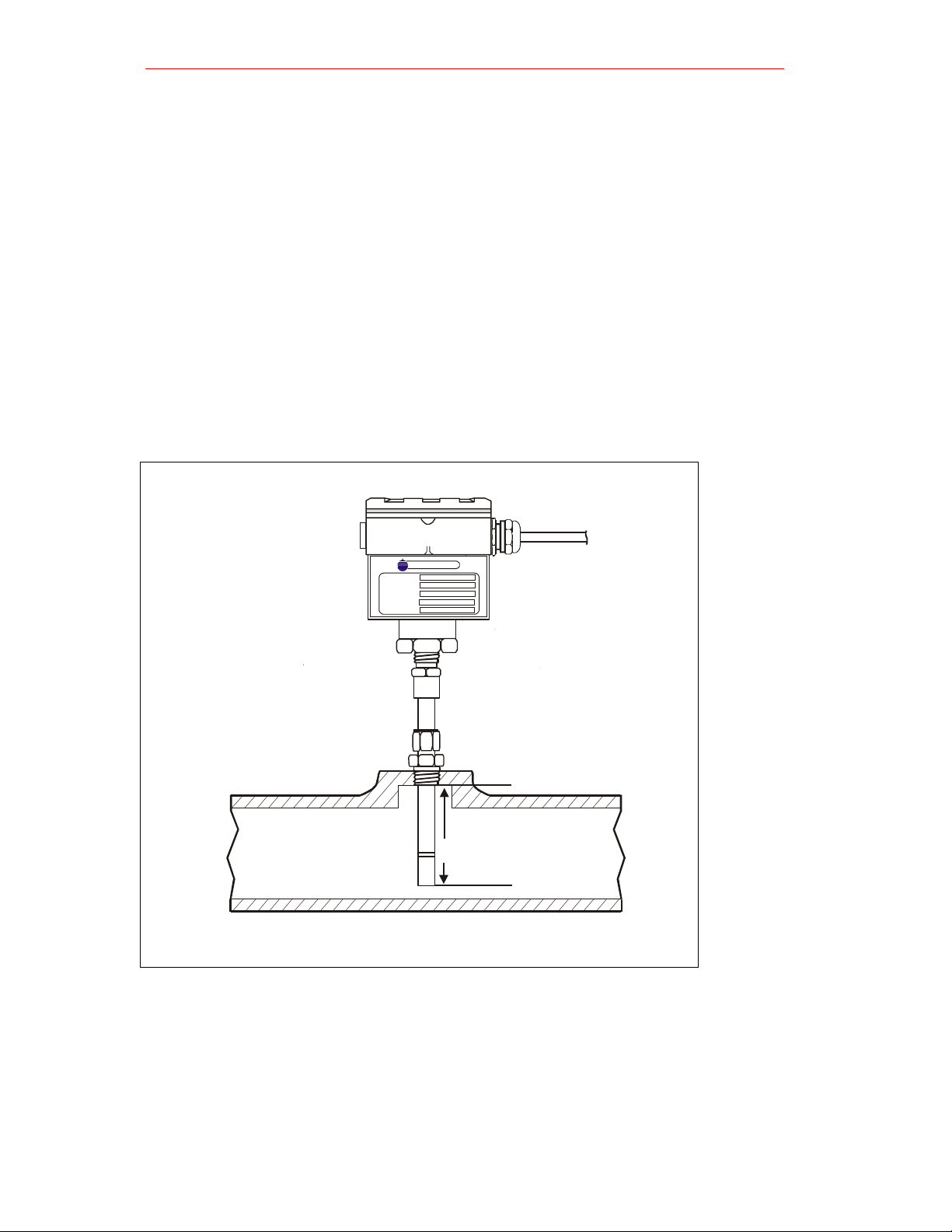
2.1 Mounting the Probe
Preferably, mount the probe vertically such that the sensor tip points down. Mount
the probe in a G 1/2 thread connection or with a flange. Be certain that the tip of the
probe does not touch the inside wall of the pipe.
Adjust the ferrule (nylon or stainless steel*) for a probe insertion length of 1”
(minimum) and tighten the compression fitting as follows:
• Hand-tighten the nut. Then, using a wrench, tighten the nut one and onehalf turns.
• Now the fitting is tight and can withstand pressure to 17 bar (250 psi)
(provided a stainless steel ferrule is used)
GENERAL EASTERN
The Humidity Experts
MMR 31
MODEL:
SERIAL NO:
9...32 VDC
SUPPLY:
DEWPOINT RANGE:
PSIG
P max:
Minimum 25mm
Fig. 3
GE General Eastern
6
Page 7
DewPro MMY31
3.0 Wiring
3.1 Wiring, General Guidelines
Caution! Caution!
The DewPro system contains electronic components that are susceptible
to damage by static electricity. Proper handling procedures must be
observed during the removal , installation, or other handling of internal boards.
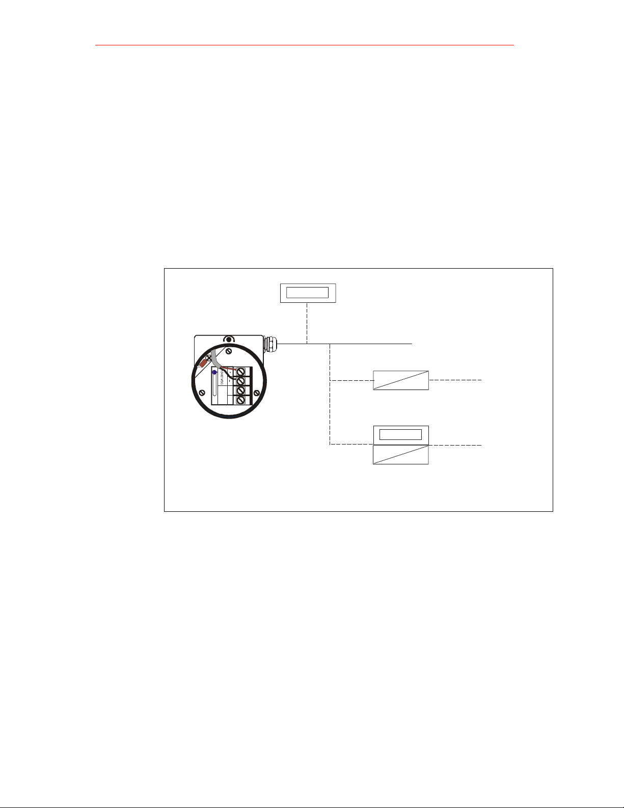
3.2 System Configuration, Various
Fig. 4
8888
GENERAL EASTE RN
The Humidity Experts
NOTE: The voltage across the +/- terminal of the DewPro should not fall below 9 V DC.
The maximum loop resistance is an important measure for selection of the supply voltage.
Each device connected to the loop causes a voltage drop. For instance, using a looppowered display with an input impedance of 50 Ohm will cause a voltage drop of 1 V DC
at 20 mA following Ohm's law. Connecting the loop to a PLC will cause a voltage drop
across its input.
When designing your loop, add up all voltage losses across the devices connected to the
loop and add 12 V. The sum will be the minimum supply voltage required from the power
supply. Calculate with a 20% safety factor.
If a display is used, configure it to the proper range: -90
for dewpoint corresponding to 4 to 20 mA.
Installation and Operation Manual
Optional loop powered
display available from
General Eastern, such as Md102
Customers power supply
24 V DC ( 9...32 V DC )
~
Power supply
available from General Eastern
8888
~
Power supply with display
and optional relay available
from General Eastern such as Md102
o
C to +10 oC (- 130 oF to + 50 oF)
115/ 2 30 V
AC
115/230 V
AC
GE General Eastern
7
Page 8

DewPro MMY31
E
N
E
R
L
E
E
R
N
x
p
E
N
E
R
A
L
E
A
S
E
R
N
y
x
p
Installation and Operation Manual
3.3 Mounting in Normal Environment
• A standard two-wire, stranded cable can be used to interconnect the
DewPro with the power source
Shielded Two
wire Cable
External Ground
G
A
The Hu m idity E
AST
erts
Capped
off
3.4 Mounting in Environments with Severe Electrical Noise
• In areas where EMI/RFI interference is likely, a shielded signal cable is to
be used for full protection. The DewPro MMY31 meets requirements of IEC
801-1 through 6 (EN 50081-1, 50082-2) when properly shielded cable is
used
Shielded Two
wire Cable
External Ground
G
TheHumidit
T
E
Fasten Shield Under
erts
Cable Clamp for
Maximum RFI Protection
Capped
off
3.5 Electrical Connection
G
E
N
E
R
A
L
E
T
h
A
e
H
S
u
m
T
i
d
i
E
t
y
E
R
x
p
e
N
r
t
s
+
24 V DC Nominal (9-32 V)
-
Standard
Fig. 5
EMI/RFI
Fig. 6
Electrical Connection
Fig. 7
GE General Eastern
8
Page 9

DewPro MMY31
Installation and Operation Manual
3.6 General Wiring Instructions
1. Unscrew the cap on top of the unit.
2. Loosen the gray cable gland located on the side of the unit.
3. Feed the cable through the conduit opening.
NOTE
4. Retighten the gray cable gland to meet IP 67 and to relieve the wire and protect the
electronics from dust and moisture.
5. Supply 9 to 32 V DC power to the terminals marked + and -.
6. If the enclosure is ordered with a ½” FNPT conduit conection, the cable gland can be
removed to connect the conduit.
: Use a standard signal cable size.
NOTE: This is the voltage that appears across the DewPro terminals. It is not
necessarily the supply voltage due to voltage loss in wire length, displays,
indicators, etc.
GE General Eastern
9
Page 10

DewPro MMY31
Installation and Operation Manual
4.0 Optional Display/User Interface
4.1 Installation
If the DewPro is equipped with an optional display / user interface follow the
procedure below to access the terminals prior to applying power. Please use Figure
18 below as a reference when removing any parts from the DewPro.
N
R
s
t
r
E
e
p
x
T
E
S
y
t
i
d
i
A
m
u
E
H
e
h
L
T
A
R
E
N
E
G
1. Unscrew and remove the protective lid from the top of the DewPro, exposing
the display module below
2. Unplug the display from the lower terminal board.
3. Carefully grasp the display bracket and pull straight up.
4. Follow the procedure outlined in Section 3.0, pages 8-10.
5. To replace the display module, locate the six holes on the underside of the
display bracket. The MMY 31 uses the holes with the additional markings
next to them.
6. Align the display bracket with the standoffs and snap the display bracket
onto the three standoffs.
7. Carefully rotate the display module on the display bracket until properly
aligned for readability.
8. Reconnect the display to the lower terminal board observing the key on the
plug and socket.
NOTE: When the display module is installed it takes over control, superseding the
rotary switch functions illustrated under Section 5.4 on page 16. Only the calibration
buttons on the printed circuit board remain active.
Fig. 18
GE General Eastern
10
Page 11

DewPro MMY31
Installation and Operation Manual
4.2 Description of the DewPro MMY31 Programming Matrix
In the DewPro mid-range moisture transmitter with display option, a matrix-style input is
used for programming the unit of measure, measuring range, error status of output, and
output adjustment. For users of other General Eastern equipment, this 'GEI matrix" format is
familiar. The following describes the features and usage of the various matrix location as
they apply to the MMY 31.
Fig. 19
The display of the DewPro MMY 31 continuously shows the current matrix location using
Fig. 20
Movement through the matrix is accomplished by using the "V" and "H" buttons to move
Numeric
Display
Bar Graph
8888
----------
-
VH
88
VH Position
Indicators
User Interface
Keys
the vertical (V) and horizontal (H) coordinates to designate the row and column,
respectively. The bar graph represents the output current in an analogue fashion (refer to
Figure 19). See the Appendix for an enlarged overview of the matrix.
MMY 31 H0 H1 H2 H3 H4 H5 H6 H7 H8 H9
Value
4 mA
(bar)
Select
Moisture Unit
see table
below
Dewpoint °C
20 mA
Display
Previous Error
ppm
mA
Unit ID
v
Software
Version
Reset To
Defaults
50 = Reset
Loop 1 at Fault
0= -10%,
1=110%, 2=Hold
Loop 1 Raw
Reading
Loop 1 D/A
Calibration
Low
Loop 1 D/A
Calibration
High
Input Locking
50 = Unlock
System Reset
50 = Reset
Display
Moisture Unit
Loop Range
Constant;
Loop
Hardware
Calibration
Access Key
Misc. Setup
Moisture
V0
Dewpoint °C
V1
V2
Pressure
Constant for
V3
ppmv comp.
V4
V5
V6
V7
V8
Display
V9
Present Error
to another row or column. For example, beginning at VH 00 and successively pressing
"V", leads the user to VH 10, VH 20, VH 30, VH 40, VH 50, VH 60, VH 70, VH 80, VH 90
and back to VH 00. At any location where a value may be changed by the user, the
desired value is programmed using the "+" and “-“ buttons.
GE General Eastern
11
Page 12

DewPro MMY31
Installation and Operation Manual
1. Reset to "Normal" Display: Pressing the 'V' and “H” buttons simultaneously
3. Default Values
This section describes the functions available to the user through the matrix. grouped by
DISPLAY AND OUTPUT MODE
1. Dewpoint display
2. Selecting the Device Unit
4.3 Special Functions of the Push buttons
returns the user to VH 00 (normal display).
2. Display Only: Note that eight (6) matrix locations me for display only and may not
be changed by the user (refer to Figure 20 or Appendix). The 'display only' fields
are as follows:
• VH 00 = normal display (in dewpoint oC)
• VH 08 = indicates digitized moisture signal
• VH 90 = during a system alarm, displays the error code for the fault
encountered
• VH 91 = during normal operation, the previous error code is displayed for
reference
• VH 92 = displays the factory issued identification number
• VH 93 = displays the factory issued reference number designating the
device type and software version
A default value is assigned to each programmable matrix field. The values are
present after a reset to factory programmed data has been executed (see VH 95).
4.4 Functions of the Matrix (Refer to Figure 16 or Appendix
common function areas. The function is accessed by positioning to the specified location
within the matrix
Location in Matrix Description of Function
VH 00
Location in Matrix Description of Function
VH 01
This is the normal display of the transmitter when in operation.
The dewpoint is shown in oC or oF, or ppm-v as selected
under VH 01.
Selects units to be displayed. Changing from oC to oF does not
change the current loop. Changing from dewpoint to ppm-v
does change the current loop.
When switching to ppm-v, the display may indicate an
NOTE:
error " 3" if the dewpoint reading is above -20 oC. (For
example, the DewPro is exposed to ambient air.)
GE General Eastern
12
Page 13

DewPro MMY31
3. Loop at Fault
Location in Matrix Description of Function
VH 07
4. Selecting the Analogue Output Offset (4 mA)
Location in Matrix Description of Function
VH 10
5. Selecting the Analogue Output Span (20 mA)
Location in Matrix Description of Function
VH 11
6. Setting the Span Value for the ppm-v Range
Location in Matrix Description of Function
VH 12
If any fault malfunction occurs, the loop can be set to either "10%" (=3.6 mA), to "110%" (=22 mA) or "Hold" (stays at last
valid value).
The dewpoint value corresponding to the analogue output
offset (4 mA) is entered here.
Caution! Ensure this is always at least 20 OC below the value
assigned to 20 mA.
Default: -90 oC
The dewpoint value corresponding to the analogue output span
(20 mA) is entered here.
Caution! Ensure this is always at least 20 oC above the value
assigned to 4 mA.
Default: + 10 oC
Selection of this field sets the span value for the ppm-v range.
NOTE: The offset is always 0 ppm-v. Do not exceed 1000
ppm-v
Default: 100
Installation and Operation Manual
GE General Eastern
13
Page 14

DewPro MMY31
SPECIAL CALIBRATION
7. Adjusting the pressure constant
Location in Matrix Description of Function
VH 30
8. Adjusting the Current Loop at 4 mA
Location in Matrix Description of Function
VH 38
9. Adjusting the Current Loop at 20 mA
Location in Matrix Description of Function
VH 39
The process pressure constant is entered in bar (absolute), which
is used to calculate ppmv. The moisture unit ppmv is the ratio of
water vapor pressure to the total process pressure and is,
therefore, independent of the process pressure. The reason is
that when compressing a gas (process pressure) all partial
pressures increase by the same factor (Daiton's Law).
The gold/aluminum oxide sensor is selective to water vapour
pressure monitoring a higher vapor pressure when the total
pressure (process pressure) increases. The formula utilized by
the analyser refers to the total pressure of 1 bar. An elevated
pressure of the process has to be corrected by programming the
actual process pressure to the matrix field VH 30.
The system should be designed to maintain a constant pressure,
for instance, by using a pressure regulator in a bypass system.
Default: 1 bar (absolute)
By connecting a mA-meter in the loop, the correct current (4 mA)
can be adjusted by increasing or decreasing the displayed digits.
NOTE: If the matrix input is locked (VH89), the calibration values
are displayed but the current output is unaffected. To enable
adjustments, VH89 has to be unlocked by entering "50" into this
field.
Selection of this field assists during calibration generating a
nominal 20 mA signal, but the actual value must be 21,92 mA, an
over range to a dewpoint of 22 oC.
By connecting a ma-meter in the loop, the correct current (21.92
mA) can be adjusted by increasing or decreasing the displayed
digits.
NOTE: If the matrix input is locked (VH89), the calibration values
are displayed but the current output is unaffected. To enable
adjustments, VH89 has to be unlocked by entering "50" into this
field.
Installation and Operation Manual
GE General Eastern
14
Page 15

DewPro MMY31
Installation and Operation Manual
MODE OF OPERATION
10. Input locking
Location in Matrix Description of Function
VH 89
11. Displaying the present Error Code
Location in Matrix Description of Function
VH 90
12. Displaying the previous Error Code
Location in Matrix Description of Function
VH 91
Any number other than "50" will lock the instrument settings
from inadvertent or unauthorized changes. (The instrument is
only unlocked at "50".)
In the event of a system fault, this field displays the diagnostic
error code for the fault encountered.
Error Code
0
1
2
3
4
5
7
When a system fault condition is cleared, the value of the error
code is stored in this location. That is, during normal operation,
the most recent error code is displayed for reference.
Description
No error
Dewpoint underrange. The current
output has fallen below the 4.00 mA
point.
Dewpoint overrange. The current
output has exceeded the 21.92 mA
level.
The instrument is no longer reading
between -90 and -20 'C dewpoint while
in ppm-v mode and has fallen off of the
internal vapor pressure table.
ppm-v overrange. The current output
has exceeded the 20 mA level. Rerange the ppm-v upper scaling limit to
keep this error from occurring.
Sensor is shorted.
Sensor is open.
GE General Eastern
15
Page 16

DewPro MMY31
13. Instrumentation Identification number
Location in Matrix Description of Function
VH 92
14. Identification Field
Location in Matrix Description of Function
VH 93
15. Set to Default Values
Location in Matrix Description of Function
VH 94
16. Resetting the Device
Location in Matrix Description of Function
VH 94
The instrumentation identification number should always read
“100”.
This field indicates the software version (ie. version 2.02 or
higher).
This field sets all factory defaults
NOTE: Anything that has been calibrated will not be reset.
The device is reset in this field.
Note: Reset the device only after field calibration using
the DewComp MCY 40 calibrator.
Installation and Operation Manual
GE General Eastern
16
Page 17

DewPro MMY31
Installation and Operation Manual
5.0 Troubleshooting
5.1 General Problems
1. The loop current is outside the range of 4-20 mA, as shown on display or current
meter.
SOLUTION: The process dewpoint is out of range. If the dewpoint is above
o
+22
C (+ 77 oF), the current will go to the fault current specified on the order or
in the matrix field VH 07. Apply dry air for a few minutes. If the dewpoint doesn't
decrease, consult factory.
SOLUTION: If the dewpoint is below -90
fault current specified on the order or in the matrix field VH 07. Move the sensor
into a wetter environment for a few minutes. If the dewpoint doesn't increase.
the cause may be a defective sensor assembly or an electronics malfunction.
Consult factory.
2. There is no current.
SOLUTION:
If the voltage is within 12-32 V DC, consult the factory.
Check voltage and polarity across +/- terminals with a DC voltmeter
o
C (-130oF), the current will go to the
GE General Eastern
17
Page 18

DewPro MMY31
6.0 Technical Specifications
Sensor element
Measuring range(s)
Recommended calibration cycle
Calibration accuracy
Repeatability
Maximum RH
Temperature coefficient
Operating and storage temperature
Max. operating pressure
Helium leak rate
Temperature coefficient
Signal output
Process connection
Probe Tube:
Sensor protection
Electronics
Power supply
Protection
Weight
Installation and Operation Manual
: Gold/aluminum oxide, capacitance
principle
: -90°C to +20°C dew point temperature;
0 to 10 ppm-v, 0 to 100 ppm-v or
0 to 1000 ppm-v (adjustable with
integrated display)
: 6 to 24 months, depending on the
application and the required accuracy
: ±2°C dewpoint
: ±1°C dewpoint
: 50% at dew point > 0°C
: < 0,2°C/°C
: -40°C to +60°C
: 120 bar (1750 psig)
: <10 -6 mbar l/s
: Td /T < 0,2°C/°C
: 4 - 20 mA, 16 µA resolution
: 1/2“ (12,7 mm) x G 1/2“ (DIN ISO 228) or
1/2“ (12,7 mm) tube x 1/2“ MNPT
compression fittings
: Stainless steel 1.4571, 1/2“ (12,7)
diameter, insertion length 2“ (50 mm) to
3,5“ (90 mm)
: Sintered filter 100 micron
: Microprocessor-controlled
: 24 VDC nominal, 12 to30 VDC range
: NEMA 4X (IP 67)
: 1,5 kg (3.2 lb)
GE General Eastern
18
Page 19

DewPro MMY31
_
S
E
R
N
Installation and Operation Manual
7.0 Accessories
7.1 Available Accessories
Accessory Description
Single power supply
Panel mount display, power supply, no relays
Panel mount display, power supply, two alarms
Panel mount display, power supply, two alarms. 4 to 20 repeating output
Consult GE General Eastern
Example
GENE
RAL EA
T
h
e
H
u
m
T
i
d
i
t
y
E
x
p
e
r
t
s
Optional loop powered
display available
from General Eastern
Optional loop-powered
display available from
General Eastern
+
Customer’s 24 V (9...32V DC)
or power supply available
from General Eastern
Example
Fig. 22
GE General Eastern
19
Page 20

DewPro MMY31
Installation and Operation Manual
8.0 Addresses
For More information, please contact one of the following GE General Eastern
offices:
USA
GE General Eastern Instruments
500 Research Drive
Wilmington, MA
Tel. +1 978 203 1900
Fax. +1 978 203 1903
Germany
GE General Eastern
Branch of GE Measurement & Sensing Technologies
Bergische Strasse 10
D – 42781 Haan
Tel. +49 2129 558 10
Fax. +49 2129 558 110
Netherlands
GE General Eastern
PO Box 49
NL - 1400 AA Bussum
Tel. +31 (0)35 698 2700
Fax. +31 (0)35 698 2699
United Kingdom
GE-TEC
General Eastern – Technical Centre
Unit 6, Block 3 Vestry Estate
Otford, Seven Oaks
Kent TN14 5EL
Tel. +44 (0) 1732 468100
Fax. +44 (0) 1732 468101
www.generaleastern.net
GE General Eastern
20
Page 21

DewPro MMY31
Installation and Operation Manual
APPENDIX
MMY 31 H0 H1 H2 H3 H4 H5 H6 H7 H8 H9
Moisture Unit
Loop Range
Constant;
Loop
Hardware
Calibration
V0
V1
V2
V3
V4
V5
V6
V7
Display
Moisture
Value
Dewpoint °C
4 mA
Pressure
Constant for
ppmv comp.
(bar)
Select
Moisture Unit
see table
below
Dewpoint °C
20 mA
ppm
mA
v
Loop 1 at Fault
0= -10%,
1=110%, 2=Hold
Loop 1 Raw
Reading
Loop 1 D/A
Calibration
Low
Loop 1 D/A
Calibration
High
Access Key
Misc. Setup
V8
V9
Display
Present Error
Display
Previous Error
Unit ID
Software
Version
Reset To
Defaults
50 = Reset
GE General Eastern
Input Locking
50 = Unlock
System Reset
50 = Reset
21
 Loading...