

Page 1
g
ASTAT ®-IBP Plus Solid State Starters
Service Instructions
DEH-40417
Page 2

Page 3

WARNINGS
All Rights Reserved
CAUTIONS
NOTES
DEH-40417
WARNINGS, CAUTIONS, AND NOTES
AS USED IN THIS PUBLICATION
Warning notices are used in this publication to emphasize that hazardous voltages, currents, or
other conditions that could cause personal injury are present in this equipment or may be
associated with its use.
Warning notices are also used for situations in which inattention or lack of equipment knowledge
could cause either personal injury or damage to equipment.
Caution notices are used for situations in which equipment might be damaged if care is not taken.
Notes call attention to information that is especially significant to understanding and operating
the equipment.
This document is based on information available at the time of its publication. While efforts have
been made to ensure accuracy, the information contained herein does not cover all details or
variations in hardware and software, nor does it provide for every possible contingency in
connection with installation, operation, and maintenance. Features may be described herein that
are not present in all hardware and software systems. GE Electrical Distribution & Control
assumes no obligation of notice to holders of this document with respect to changes subsequently
made.
GE Electrical Distribution & Control makes no representation or warranty, expressed, implied, or
statutory, with respect to, and assumes no responsibility for the accuracy, completeness, sufficiency,
or usefulness of the information contained herein. No warrantees of merchantability or fitness for
purpose shall apply.
The following are trademarks of GE Company:
ASTAT®-IBP Plus
©Copyright 2001 GE Company
i
Page 4

ASTAT ®-IBP Plus Service Instructions
Table of Contents
Cover Removal and Replacement............................................................................................1
Logic Board Replacement.......................................................................................................2
Power Supply Board Replacement ...........................................................................................3
Protection Board Replacement................................................................................................5
SCR Module Replacement (Sizes K, L, and Y)...........................................................................6
SCR Module Replacement (Sizes M, Z, and N)..........................................................................7
SCR Module Replacement (Sizes P, Q, and R)..........................................................................8
SCR Module Replacement (Size S)...........................................................................................9
Trouble-Shooting Guide........................................................................................................11
Renewal Parts List.................................................................................................................12
ii Prices and data subject to change without notice.
Page 5
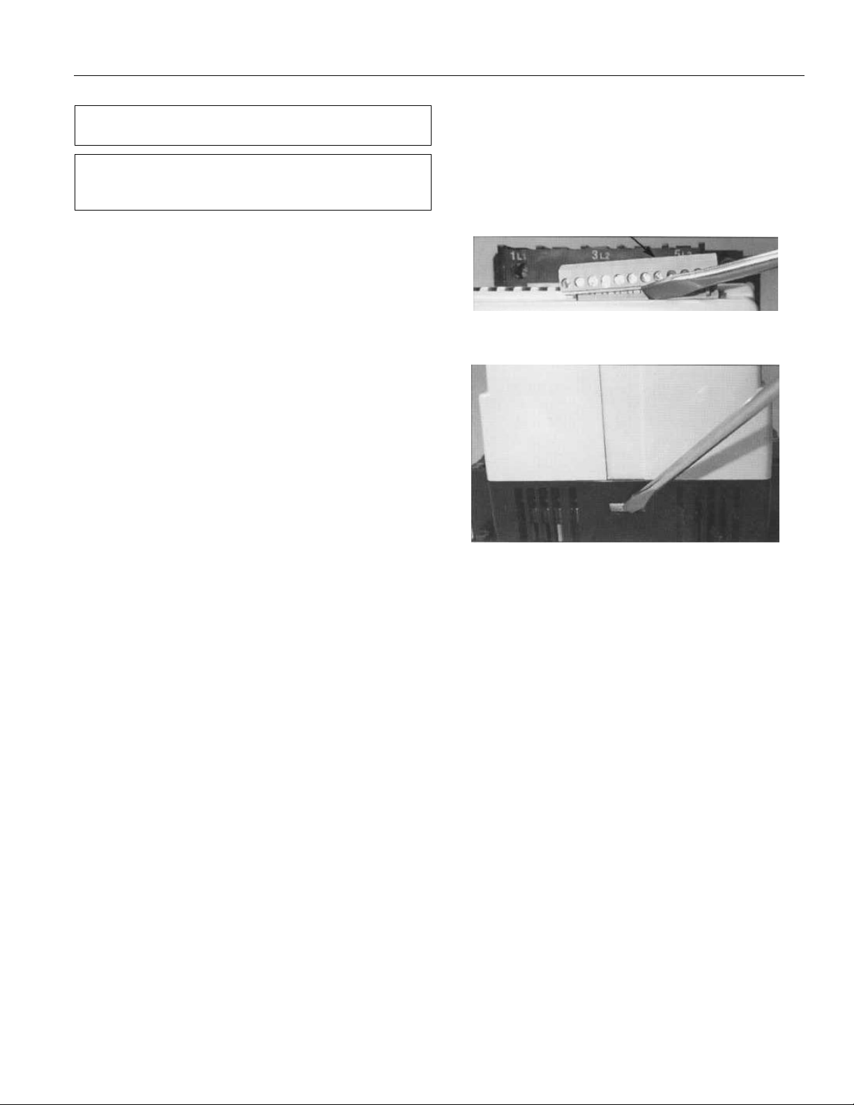
WARNING: Power must be removed from the ASTATIBP before any servicing operation.
AVERTISSEMENT: Le courant doit être enlevé du
ASTAT-IBP avant de procéder à toute opération de
service.
Cover Removal and Replacement
1. Remove the two 12-point terminal connectors by
inserting a flat-head screwdriver between the
terminal connector and the ASTAT-IBP cover, as
illustrated in Figure 1.
Do not remove the wiring from the terminal
connectors.
Carefully release the terminal connector from the
pins. Carefully pull the terminal connectors, with
the wiring, straight off the ASTAT-IBP starter.
2. Remove the plastic cover by pressing and releasing
the plastic tab on each side of the cover with a flathead screwdriver, as illustrated in Figure 2.
3. To reattach the cover, lower it over the circuit
boards. Carefully push down on the cover until the
two tabs snap into place. It may be necessary to push
in slightly on the outside of the lower plastic
housing.
4. Replace the terminal connectors through the plastic
cover onto the connector strips. Ensure that the
terminal connectors snap into place.
ASTAT ®-IBP Plus Service Instructions
Terminal Connector
Cover
Figure 1. Removing the terminal connectors.
Figure 2. Removing the cover.
Prices and data subject to change without notice. 1
Page 6
ASTAT ®-IBP Plus Service Instructions
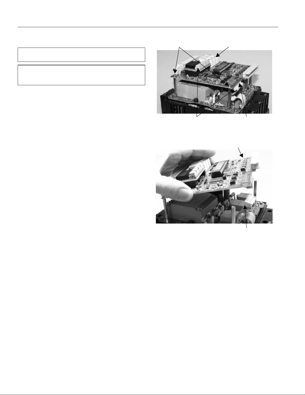
Logic Board
Logic Board
Logic Board Replacement
CAUTION: Always handle circuit boards by their edges
and do not distort the parts on the circuit boards.
ATTENTION: Il faut toujours manipuler les plaques de
circuits par leurs côtés et ne pas déformer les pièces sur
les plaques de circuits.
1. Remove the ASTAT-IBP cover as described in steps
1–2 of Cover Removal and Replacement.
2. Unplug the two ribbon cables from the Logic Board,
as shown in Figure 3.
3. Remove the four corner screws holding the Logic
Board to the stand-offs below the Logic Board. Lift
the Logic Board straight up to remove it, as
illustrated in Figure 4.
4. Reassemble the Logic Board to the starter. With the
display on the Logic Board at the upper left corner,
place the board on the stand-offs. Reattach the four
screws holding the Logic Board to the stand-offs.
5. Reattach the two ribbon cables. Ensure that the
ribbon cable at the bottom of the ASTAT-IBP is fully
seated on both circuit boards and that the ribbon
cable does not interfere with or touch the cover.
6. Reinstall the plastic cover and the terminal
connectors as described in steps 3–4 of Cover Removal
and Replacement.
Screws
Unplug Cable
Ribbon
Power Supply
Figure 3. Logic board and part locations.
Board
Cable Ribbon
Figure 4. Removing the Logic Board.
2 Prices and data subject to change without notice.
Page 7

ASTAT ®-IBP Plus Service Instructions
Screw
Power Supply Board Replacement
The Power Supply Board is located as shown in Figure 5.
It contains gray and orange transformers visible from the
sides.
1. Remove the following components:
a. The cover, as described in steps 1–2 of Cover
Removal and Replacement.
b. The Logic Board, as described in steps 2–3 of
Logic Board Replacement.
2. Remove the four screws holding the Power Supply
Board to the black plastic housing, as shown in
Figure 6.
3. If a yellow-green wire is connected to the bottom of
the Power Supply Board, it must be disconnected.
Lower the top of the Power Supply Board to view the
red and white gate leads to the SCRs, as shown in
Figure 7.
NOTE: Check the red and white gate wires for a marked
number before removing these wires. Each gate wire
must have a number corresponding to the terminal
numbers (1–12) on the Power Supply Board to facilitate
reassembly.
Power Supply Board
Ribbon Cable
Figure 5. Location of the Power Supply Board.
NOTE: Vérifier les chiffres sur les fils de porte avant
d’enlever ceux-ci. Chaque fil de porte doit avoir un
chiffre correspondant aux chiffres de la borne (1–12)
sur la plaque de la boîte d’alimentation pour faciliter le
réassemblage.
4. With a small screwdriver, remove the red and white
gate wires from the small four-point gate Terminal
Boards, one on the component side and two on the
solder side of the Power Supply Board.
These wires must be reconnected to the new Power
Supply Board at the proper number terminals for
proper operation of the starter.
5. Lift off the Power Supply Board. Remove and save
the hex stand-offs, nuts, and washers from the Power
Supply Board for use on the replacement board.
6. Attach the stand-offs to the new Power Supply Board.
Place the new Board in position in the ASTAT-IBP.
Figure 6. Removing the screws holding the Power Supply Board
to the housing.
Gate Leads
Bottom of Power
Supply Board
Protection Board
Gate Terminal
Board
Figure 7. Gate leads, Power Supply Board, and Protection Board.
Prices and data subject to change without notice. 3
Page 8

ASTAT ®-IBP Plus Service Instructions
7. Reconnect the red and white gate wires to the fourpoint Terminal Boards, one on the component side
and two on the solder side of the Power Supply
Board, as illustrated in Figures 8, 9, and 10.
8. Secure the Power Supply Board with the four screws
removed earlier.
9. Reinstall the following components:
a. The Logic Board, as described in steps 4–5 of
Logic Board Replacement.
d. The cover, as described in steps 3–4 of Cover
Removal and Replacement.
Figure 8. Gate lead connections for sizes K, L, and Y.
Figure 9. Gate lead connections for sizes M, Z, and N.
Figure 10. Gate lead connections for sizes P, Q, R, and S.
4 Prices and data subject to change without notice.
Page 9

Protection Board Replacement
Wire Connectors
ASTAT ®-IBP Plus Service Instructions
1. Remove the following components:
a. The cover, as described in steps 1–2 of Cover
Removal and Replacement.
b. The Logic Board, as described in steps 2–3 of
Logic Board Replacement.
c. The Power Supply Board, as described in steps 2–
5 of Power Supply Board Replacement.
2. Remove the six wire connectors from the Protection
Board, as shown in Figure 11. Note the locations of
these terminals for reassembly.
3. Disconnect the four leads from the two current
transformers and the two leads from the thermostat
connecting to the six-point Terminal Board, located
at the top-right edge of the Protection Board. Label
these leads to ensure that they are connected to the
same terminals on the new Protection Board.
4. Loosen the four screws holding the Protection Board
to the housing. Remove the Protection Board from
the ASTAT-IBP.
5. Place the new Protection Board in position in the
ASTAT-IBP and secure it with the four mounting
screws to the housing.
6. Attach the four current transformer leads and the
two thermostat leads to the six-point Terminal
Board.
7. Attach the six push-on wire connectors to the
Protection Board.
8. Reinstall the following components:
a. The Power Supply Board, as described in steps 6–
9 of Power Supply Board Replacement.
b. The Logic Board, as described in steps 4–5 of
Logic Board Replacement.
c. The cover, as described in steps 3–4 of Cover
Removal and Replacement.
Six-Point
Terminal Board
Protection Board
Mounting Screw
Figure 11. Removing the wire connectors from the Protection
Board.
Prices and data subject to change without notice. 5
Page 10

ASTAT ®-IBP Plus Service Instructions
SCR Module Replacement (Sizes K, L,
and Y)
This procedure requires the following tools and
materials:
• #2 Philips-head screwdriver, 3/16" Allen wrench,
torque wrench
• Scotchbrite or equivalent abrasive
• Mild solvent to clean mounting surfaces
• Electrolube 2GX or equivalent thermal grease
1. Loosen the screws holding the MOVs and bus bars
to the SCR Module to be replaced, as illustrated in
Figure 12, and remove the MOVs and bus bars.
2. Remove the mounting screws at each end of the SCR
Module, as shown in Figure 13, then lift out the
Module. Retain all the parts and hardware removed
from the SCR Module for reassembly with the
replacement Module.
3. Clean the heat sink surface of the replacement
Module with a fine abrasive, such as Scotchbrite.
Remove all particles from the heat sink surface and
wipe the SCR mounting surface with a mild solvent.
Apply a light coat of thermal grease, such as
Electrolube 2GX to both the SCR and heat sink
surfaces.
4. Place the contact face of the SCR Module on the
mating heat sink surface. Move the Module back
and forth several times to distribute the thermal
grease evenly over the contact surfaces.
5. Attach the SCR Module to the heat sink with the
screws removed earlier. Tighten the screws to 44 inlb.
6. Reattach the bus bars and MOVs to the SCR Module
with the screws removed earlier. Tighten the screws
to 26 in-lb.
Figure 12. Removing the MOVs and bus bars from an SCR to be
replaced.
Figure 13. Removing the SCR module.
6 Prices and data subject to change without notice.
Page 11

SCR Module Replacement (Sizes M, Z,
and N)
This procedure requires the following tools and
materials:
• #2 Philips-head screwdriver, 3/16" Allen wrench,
torque wrench
• Scotchbrite or equivalent abrasive
• Mild solvent to clean mounting surfaces
• Electrolube 2GX or equivalent thermal grease
ASTAT ®-IBP Plus Service Instructions
1. Loosen the screws holding the MOVs and bus bars
to the SCR Module to be replaced, shown in Figure
14, and remove the MOVs and bus bars.
2. Remove the mounting screws at each end of the SCR
Module, then lift out the Module. Retain all parts
and hardware removed from the SCR Module for
reassembly with the replacement Module.
3. Clean the heat sink surface of the replacement
Module with a fine abrasive, such as Scotchbrite.
Remove all particles from the heat sink surface and
wipe the SCR mounting surface with a mild solvent.
Apply a light coat of thermal grease, such as
Electrolube 2GX to both the SCR and heat sink
surfaces.
4. Place the contact face of the SCR Module on the
mating heat sink surface. Move the Module back
and forth several times to distribute the thermal
grease evenly over the contact surfaces.
5. Attach the SCR Module to the heat sink with the
screws removed earlier. Tighten the screws to 44 inlb.
6. Reattach the bus bars and MOVs to the SCR Module
with the screws removed earlier. Tighten the screws
to 80 in-lb.
Figure 14. Location of SCRs on size M, Z, N ASTAT-IBP.
Prices and data subject to change without notice. 7
Page 12

ASTAT ®-IBP Plus Service Instructions
SCR Module Replacement (Sizes P, Q,
and R)
This procedure requires the following tools and
materials:
•1/2" wrench, 3/16" Allen wrench, torque wrench
• Scotchbrite or equivalent abrasive
• Mild solvent to clean mounting surfaces
• Electrolube 2GX or equivalent thermal grease
1. Disconnect the control wiring harness for the SCRs
to be replaced. If necessary, disconnect the wiring
harness of the CTs.
2. Remove the bolt holding the busbar to the line side
of the SCR Module.
3. Remove the bolt holding the CT, spacer, and loadside busbar to the SCR Module, as shown in Figure
15.
4. Remove the four screws holding the SCR Module to
the mounting plate, as shown in Figure 16.
5. Lift out the SCR Module, as shown in Figure 17.
Retain all parts and hardware for reassembly with
the replacement Module.
6. Remove the MOV by disconnecting it at the spade
connectors. Attach the MOV to the replacement
SCR Module in the same manner.
7. Clean the heat sink surface of the replacement
Module with a fine abrasive, such as Scotchbrite.
Remove all particles from the heat sink surface and
wipe the SCR mounting surface with a mild solvent.
Apply a light coat of thermal grease, such as
Electrolube 2GX to both the SCR and heat sink
surfaces.
8. Place the new SCR Module in the proper position on
the mounting surface. Move the Module back and
forth several times to evenly distribute the grease on
the plate.
9. Secure the SCR Module to the mounting plate with
the screws removed earlier. Tighten the screws to 44
in-lb torque.
10. Reattach the busbars, CT, and spacer to the SCR
Module with the bolts removed earlier. Tighten the
bolts to 150 in-lbs torque.
11. Attach the wiring harness of the new SCR Module to
its mating piece. Attach the wiring harness of the
CTs, if necessary.
Figure 15. Disconnecting the SCR load side..
Figure 16. Removing the SCR mounting screws.
Figure 17. Removing an SCR Module.
8 Prices and data subject to change without notice.
Page 13

SCR Module Replacement (Size S)
This procedure requires the following tools and
materials:
•9/16" wrench, 11/16" wrench, 3/16" Allen wrench,
torque wrench
• Scotchbrite or equivalent abrasive
• Mild solvent to clean mounting surfaces
• Electrolube 2GX or equivalent thermal grease
1. Disconnect the control wiring harness for the SCRs
to be replaced. If necessary, disconnect the wiring
harness of the CTs.
2. Remove the bolt holding the busbars connected to
the blocks on the load and line sides of the SCR
Module, as shown in Figure 18.
3. Remove the bolt holding the CT, the threaded stud,
and the load-side busbar from the Module.
4. Remove the bolts holding the load-side lug in place.
Remove the lug.
5. Remove the L-shaped busbar and CT, if applicable,
from the assembly, as shown in Figure 19.
6. Remove the four screws holding the SCR Module to
the mounting plate, as shown in Figure 20.
ASTAT ®-IBP Plus Service Instructions
Figure 18. Removing the busbar mounting bolt.
Figure 19. Removing the L-shaped busbar.
Figure 20. Removing the SCR mounting screws.
Prices and data subject to change without notice. 9
Page 14

ASTAT ®-IBP Plus Service Instructions
7. Lift out the SCR Module, as shown in Figure 21.
Retain all parts and hardware for reassembly with
the replacement Module.
8. Remove the threaded stud from the SCR Module
and attach it to the new Module. Tighten to 200 inlb torque.
9. Clean the heat sink surface of the replacement
Module with a fine abrasive, such as Scotchbrite.
Remove all particles from the heat sink surface and
wipe the SCR mounting surface with a mild solvent.
Apply a light coat of thermal grease, such as
Electrolube 2GX to both the SCR and heat sink
surfaces.
10. Place the new SCR Module in the proper position on
the mounting surface. Move the Module back and
forth several times to evenly distribute the grease on
the plate.
11. Secure the SCR Module to the mounting plate with
the screws removed earlier. Tighten the screws to 44
in-lb torque.
12. Reattach the load-side lug, L-shaped busbar, and
CT, if applicable. Tighten the mounting bolts to 200
in-lb torque.
13. Reattach the busbars to the SCR Module. Tighten
the mounting bolts to 150 in-lb torque.
14. Attach the wiring harness of the new SCR Module to
its mating piece. Attach the harness of the CTs, if
necessary.
Figure 21. Removing the SCR Module from the mounting plate..
10 Prices and data subject to change without notice.
Page 15

ASTAT ®-IBP Plus Service Instructions
Troubleshooting Guide
This guide is provided for troubleshooting and isolating common problems. It does not cover every possible situation.
Contact the Customer Support Center at 800-843-3742 if any problem is not resolved by these procedures.
Symptom or Error & (Error Code)Symptom or Error & (Error Code) Possible CausePossible Cause Measures to Be TakenMeasures to Be Taken
Display OFF
Equipment does not respond to STOP /
START controls
Frequency error (admits
45Hz ≤ f main ≤ 65Hz) (Ex10)
Overload trip (Ex11) Excessive load or excessive current
Synchronism loss (Ex13) Phase 1L1 1L1 lost Check 1L11L1 phase
Phase A, B, C thyristor (Ex14)
(Ex15)
(Ex16)
Heatsink thermostat (Ex17) Heatsink thermostat tripped by
Motor thermistor(Ex18) Motor thermistor tripped by
Phase A, B, C loss (Ex19)
(Ex20)
(Ex21)
Stalled rotor (Ex22) Equipment detected stalled motor
Internal error (Ex23) Micro-controller malfunction Check IC1 and IC8 are correctly inserted
Long start time (Ex25) Current limit condition present more
Lock-out (Ex27) The time between startings is less
Undervoltage (Ex28)
Overvoltage (Ex29)
Undercurrent (Ex30)
Overcurrent (Ex31)
No control voltage.
Main breaker tripped or fuse blown
F1 fuse blown on power supply PCB Check and change.
Bad connection of flat ribbon wire
joining power supply PCB to control
PCB
F2 fuse blown on power supply PCB Check and change.
No 1L11L1 phase or frequence is out of
range
during starting
Short circuited thyristor Check thyristor module.
No output phases Check 2T1, 4T2 2T1, 4T2 and 6T3 6T3 phases
overheating or defective
overheating or defective
No input / output phases Check power wire harness for 1L1,1L1,
Defective thyristor or ribbon wire
harness loose or defective
rotor
than2 x ta sec. or 240 sec. (ta =
acceleration ramp time)
that the adjusted in parameter "LKxx"
The line voltage exceeds of limit set in
parameters "UVxx" or "OVxx"
The motor current exceeds of limit set
in parameters "UCxx" or "OCxx"
Check wire harness and control voltage
Verify connectors.
Check power supply board and logic
board for 5VDC. Use a DC voltmeter on
the power supply board, (-) lead of
voltmeter on the top lead of C6 (located
next to the black heatsink on the right
edge of the power supply board) and the
(+) lead of voltmeter on top lead of Diode
AD21 or R25 (located on the upper right
corner of the power supply board.)
Check 1L11L1 phase and/or mains
frequence
Verify overload conditions during starting
time and steady state. Check settings in
parameters "Nxxx", "Lxxx", and "oxxx"
Check ground connections and voltage to
ground.
Poor ribbon cable connection
Check for adequate ventilation.
Check thermostat and wiring
Check thermistor and wiring, if no
thermistor terminal 5 and 6 must be
jumpered
3L2, 5L3, 2T1, 4T2 3L2, 5L3, 2T1, 4T2 and 6T36T3
Verify gate and cathode wire harness.
Verify thyristors
Restart equipment and check for an
appreciable loss in motor speed at any
time
in their sockets.
Check for noise on control voltage power
or line
Increase current limit and / or acceleration
ramp time
Check if settings are correct.
This protection may be disabled
Check if settings are correct.
This protection may be disabled
Check if settings are correct.
This protection may be disabled
Prices and data subject to change without notice. 11
Page 16

ASTAT ®-IBP Plus Service Instructions
Renewal Parts List
The following parts and assemblies are available as replacement parts for ASTAT-IBP Solid State Starters. Renewal
parts as furnished may not be identical to the original parts since design changes may have been made in the interim.
The parts supplied will, however, be interchangeable with the original parts.
Catalog NumberCatalog Number
DescriptionDescription Where UsedWhere Used
SCR Module
Bypass Contactor
Protection Circuit Board
Logic Printed Circuit Board with EPROM ALL QIX000150 1 650.00
Power Supply PCB ALL QIX000151 1 360.00
MOV (with terminals and insulators)
Terminal Strip (Logic P.C.B.) All, 12-point QIX000159 1 16.00
Terminal Strip (Control Power Input to
ASTAT)
Type GMC, 250 Vac)
Ribbon Cable, Top-Logic Board to Power
Supply Board
Ribbon Cable, Bottom-Logic Board to
Protection Board
Thermostat QC2K,L,M QIX000165 1 10.00
Plastic Cover-ASTAT-IBP Plus ALL QIX000166 1 30.00
À List Price, GO-10C2.
QI3KDP QIX000111 1/phase $117.00
QI3LDP QIX000112 1/phase 117.00
QI3YDP QIX000113 1/phase 117.00
QI3MDP QIX000114 QIX000115 QIX000116 1/phase 430.00
QI3ZDP QIX000117 QIX000118 QIX000119 1/phase 430.00
QI3NDP QIX000120 QIX000121 QIX000122 1/phase 430.00
QI3PDP QIX000123 QIX000124 QIX000125 1/phase 945.00
QI3QDP QIX000126 QIX000127 QIX000128 1/phase 945.00
QI3RDP QIX000129 QIX000130 QIX000131 1/phase 945.00
QI3SDP QIX000132 QIX000133 QIX000134 1/phase 1,512.00
QI3(K,L)DP QIX000135 1 295.00À
QI3(Y,M)DP QIX000136 1 475.00À
QI3(Z,N)DP QIX000137 1 945.00À
QI3(P,Q,R)DP QIX000138 1 1800.00À
QI3SDP QIX000139 1 2700.00
QI3KDP QIX000140 1 140.00
QI3LDP QIX000141 1 140.00
QI3YDP QIX000142 1 140.00
QI3MDP QIX000143 1 140.00
QI3ZDP QIX000144 1 140.00
QI3NDP QIX000145 1 140.00
QI3PDP QIX000146 1 140.00
QI3QDP QIX000147 1 140.00
QI3RDP QIX000148 1 140.00
QI3SDP QIX000149 1 140.00
QI3KDP QIX000154 1/phase 40.00Current Transformer
ALL Others QIX000155 1/phase 120.00
QI3(K,L,Y)DP QIX000156 2/phase 35.00
QI3(M,Z,N)DP QIX000157 2/phase 35.00
QI3(P,Q,R,S)DP QIX000158 2/phase 35.00
All, 5-point QIX000160 1 10.00
F2, ALL, 500mA QIX000161 1 3.00Fuses on Power Supply Board (Bussman
F1, ALL, 2A QIX000162 1 3.00
ALL QIX000163 1 5.00
ALL QIX000164 1 6.00
Phase 1Phase 1 Phase 2Phase 2 Phase 3Phase 3
Req.Req.
Qty.Qty.
ListList
Price,Price,
GO-11GGO-11G
12 Prices and data subject to change without notice.
Page 17

Page 18

These instructions do not cover all details or variations in equipment nor do they provide for every possible
contingency that may be met in connection with installation, operation, or maintenance. Should further
information be desired or should particular problems arise that are not covered sufficiently for the purchaser’s
purposes, the matter should be referred to the GE Company.
DEH-40417 0901 © 2001 General Electric Company
g
GE Industrial Systems
General Electric Company
41 Woodford Ave., Plainville, CT 06062
 Loading...