

Page 1
For answers to your Monogram,® GE Profile™ or
GE® appliance questions, visit our website at
geappliances.com or call GE Answer Center® service,
800.626.2000.
370405
Specification Revised 11/09
DDC4500T
GE® 5.4 Cu. Ft. Large Capacity Modular Commercial Gas Dryer
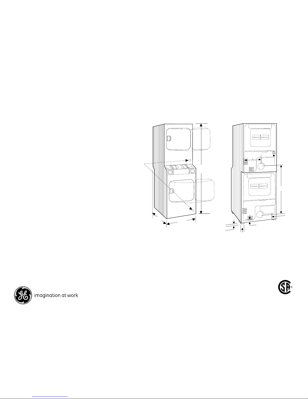
Dimensions and Installation Information (in inches)
Exhaust Options: Shipped with exhaust to the rear.
Gas model offers 2-way venting: left, right, or rear.
Maximum recommended exhaust duct length is 15
feet of 4" rigid ducting with two 90° elbows and 4" a
dampered wall cap.
(See Installation Instructions.)
Requirements:
Gas – 115 Volts, 60 Hertz single phase. An individual
branch circuit, properly grounded for a 3-prong
outlet, fused for 15- or 20-amp is required for each
dryer. Gas rate input, 22000 BTU/Hr. Maintains the
thermostatically controlled heat flow to dry clothes
gently. Longer cool down period on Permanent Press
cycle helps prevent heat-set wrinkles. Separate
thermostat controls lower temperatures for Knit cycle
drying. Factory equipped for natural gas. Tested
for LP gas. A conversion kit is required for LP gas.
Check installation instructions for correct kit number.
Have a qualified technician install the conversion kit.
Equipped with energy saving Glo-Bar ignition.
77
27
27
Gas Dryer
only
Access
Panel
Access
Panel
11-3/4
41-5/8
3-1/2
3/4
1-7/8
2-3/8
Note: Dimensions and specifications shown here are correct at the time this sheet was printed. Before
proceeding with construction or rough-in, check installation instructions that came with your unit.
Specifications, dimensions and design are subject to change without notice.
Note: Wall anchor chain provided for gas models only.
Front View Rear View
Page 2
For answers to your Monogram,® GE Profile™ or
GE® appliance questions, visit our website at
geappliances.com or call GE Answer Center® service,
800.626.2000.
370405
Specification Revised 11/09
DDC4500T
GE® 5.4 Cu. Ft. Large Capacity Modular Commercial Gas Dryer
Dimensions and Installation Information (in inches)
For complete information, see installation instructions packed with your dryer.
Important Note:
GE Kit Number WE14X70 needed when converting rear exhaust to bottom or side.
(On large capacity models.)
Ducting Materials:
For best performance, this dryer should be vented with 4" diameter all rigid metal
exhaust duct. If rigid metal duct cannot be used, then UL-listed flexible metal (semirigid) ducting can be used (Kit WX08X10077). In special installations, it may be
necessary to connect the dryer to the house vent using a flexible metal (foil-type)
duct. A UL-listed flexible metal (foil-type) duct may be used ONLY in installations
where rigid metal or flexible metal (semi-rigid) ducting cannot be used AND where a
4” diameter can be maintained throughout the entire length of the transition duct.
Please see installation instruction packed with your dryer for complete instructions
when using flexible metal (foil type) ducting.
Exhaust Length Calculation
1. Determine the number of 90° turns needed for your installation. If you exhaust to
the side or bottom of dryer, add one turn.
2. The maximum length of 4' rigid (aluminum or galvanized) duct which can be
tolerated is shown in the table.
A turn of 45° or less may be ignored. Two 45° turns within the duct length should be
treated as a 90° elbow. A turn over 45° should be treated as a 90° elbow.
Dryers must be exhausted to the outside.
Caution: For personal safety do not terminate exhaust into a chimney, under any
enclosed house floor (crawl space), or into an attic, since the accumulated lint could
create a fire hazard or moisture could cause damage. Never terminate the exhaust
into a common duct or plenum with a kitchen exhaust, since the combination of lint
and grease could create a fire hazard.
Exhaust ducts should be terminated in a dampered wall cap to prevent back drafts,
bird nesting, etc. The wall cap must also be located at least 12" above the ground or
any other obstruction with the opening pointed down.
Special Installation Requirements
Alcove or Closet Installation:
• If your dryer is approved for installation in an alcove or closet, it will be stated on a label on
the dryer back.
• The dr yer MUST be exhausted to the outside.
• Minimum clearances between dryer cabinet and adjacent walls or other sur faces are:
0" either side
3" front and rear
• Minimum vertical space from floor to overhead cabinets, ceilings, etc. is 52".
• Closet doors must be louvered or otherwise ventilated and must contain a minimum of 60
sq. in. of open area equally distributed.
If this closet contains both a washer and a dryer, doors must contain a minimum of 120 sq.
in. of open area equally distributed.
• The closet should be vented to the outdoor s to prevent gas pocketing in case of a gas leak in
the supply line.
• No other fuel-burning appliance shall be installed in the same closet with the dr yer.
Bathroom or Bedroom Installation:
• The dryer MUST be exhausted to the outdoors.
• The installation must conform with the local codes, or in the absence of local codes, with the
National Electric Code and National Fuel Gas Code, ANSI Z223 for gas dryers.
Minimum Clearances other than Alcove or Closet Installation:
• Minimum clearances to combustible sur faces
0" both sides
3" rear
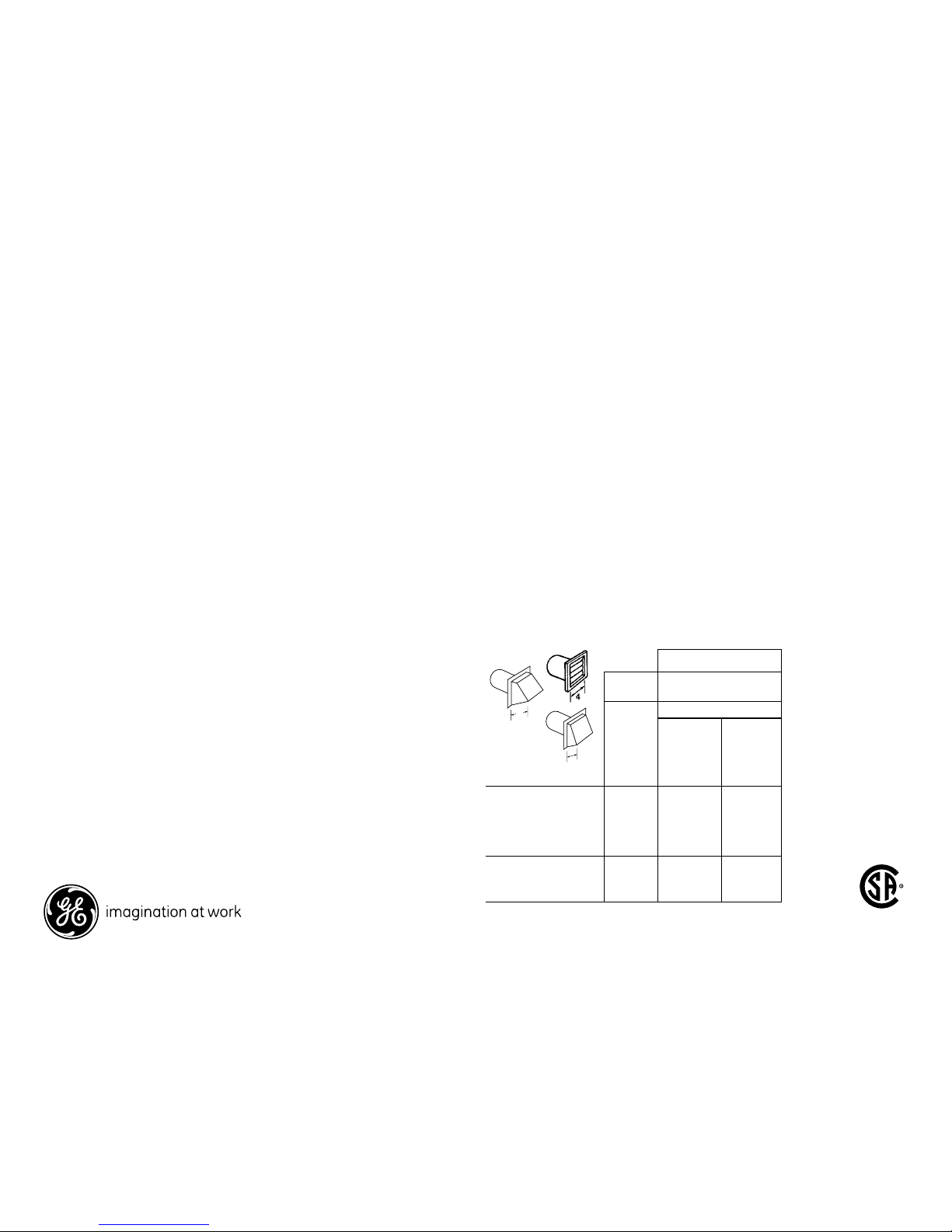
Dryer Exhausting Information – Use Metal Duct Only
Best performance
Domestic
dryer models
Maximum length of 4"
dia. rigid metal duct
Number
of
90°
turns
Exhaust hood type
A
4"
opening
B
2-1/2"
opening
5.7 cu. ft., capacity
electric and
gas dryers
0
1
2
3
4
60 ft.
52 ft.
44 ft.
32 ft.
28 ft.
48 ft.
40 ft.
32 ft.
24 ft.
16 ft.
5.4 cu. ft., capacity
electric and
gas dryers
0
1
2
45 ft.
35 ft.
25 ft.
30 ft.
20 ft.
10 ft.
A
4
B
2-1/2
A
Page 3

For answers to your Monogram,® GE Profile™ or
GE® appliance questions, visit our website at
geappliances.com or call GE Answer Center® service,
800.626.2000.
370405
Specification Revised 11/09
DDC4500T
GE® 5.4 Cu. Ft. Large Capacity Modular Commercial Gas Dryer
Dimensions and Installation Information (in inches)
Features and Benefits
• Large Capacity (5.4 Cu. Ft.)
• Commercial Modular Two-Unit Dryer System
• Automatic Dry Control
• Up-Front Lint Filter
• 3 Cycles: Cottons, Permanent Press, Delicates/Synthetic/Knits
• 3 Heat Selections
• Porcelain Drum Interior
• Front Serviceable
• Extra-Large Door Opening
• Reversible Door
• Coin slide CKTHDV8 available through GE or direct from ESD
(two kits are needed)
• Model DDC4500TWH – White (Gas)
 Loading...