

Page 1
10
- WARNING RISK OF FIRE
• To reduce the risk of severe injury or death, follow all installation instructions.
• Clothes dryer installation must be performed by a qualified installer.
• Install the clothes dryer according to these instructions and in accordance with local codes. Inthe absenceof local codes,
installationmust complywith NationalFuelGas Code,ANSIZ223.1/NFPA54 orthe CanadianNatural Gasand PropaneInstallationCode,
CSA B149.1.
•California Safe Drinking Water and Toxic Enforcement Act
This act requires the governor of California to publish a list of substances known to the state to cause cancer, birth defects
or other reproductive harm and requires businesses to warn customers of potential exposure to such substances. Gas
appliances can cause minor exposure to four of these substances, namely benzene, carbon monoxide, formaldehyde and soot,
caused primarily by the incomplete combustion of natural gas or LP fuels. Properly adjusted dryers will minimize incomplete
combustion. Exposure to these substances can be minimized further by properly venting the dryer to the outdoors.
• This dryer must be exhausted to the outdoors.
• Use only4" rigidmetal ducting for exhaustingthe clothes dryerto the outdoors.
• DO NOTinstall a clothes dryer with flexible plastic ducting materials. If flexible metal (semi-rigid or foil-type) duct is installed,
it must be ULlisted and installed in accordance with these instructions and local codes. Flexible venting materials are
known to collapse, be easily crushed, and trap lint. These conditions will obstruct dryer airflow and increase the risk of fire.
• Do not install or store this appliance in any location where it could beexposed to water and or weather.
• Save these instructions. (Installers: Be sure to leave these instructions with the customer).
BEFORE YOU BEGIN
Reedthese instructions completelg end cerefullg.
• IMPORTANT- Savethese instructions for local inspector's use.
• IMPORTANT- Observe all governing codes and ordinances.
• Note to Instoller - Besure to leave these instructions with the customer.
• Note to Customer- Keepthese instructions with your Owner's Manualfor future
reference
• Beforethe old dryer is removed from service or discarded, remove the dryer door.
• Inspect the dryer exhaust outlet and straighten the outlet walls if they are bent.
• Service information and the wiring diagram are located in the control console.
• Do not allow children on or in the appliance. Close supervision of children is
necessary when the appliance is used near children.
• Install the dryer where the temperature is above 50°Ffor satisfactory operation
of the dryer control system.
• Product failure due to improper installation is not covered under the Warranty.
The ANSI Z21.5.1 standard requires the following safety
- kWAR N ING Foryour safety the information
in this manual must be followed to minimize the risk
of fire or explosion or to prevent property damage,
personal injury or death.
-Do not store or use gasoline or other flammable vapors
and liquids inthe vicinity of this or any other appliance.
-WHAT TO DOIFYOUSMELLGAS
•Do not light any appliance.
• Donot touch any electrical switch; do not useany phone
inyour building.
•Clearthe room,building or area of all occupants.
• Immediately call your gas supplier from a neighbor's
phone. Followthe gas supplier's instructions.
• Ifyou cannot reachyour gas supplier,call the fire
department.
-Installation and service must be performed by a qualified
installer,service agency, or the gas supplier.
cautions be posted and displayed in a prominent
location:
a. Instructions to be followed in the event the user smells
gas. The information to be posted shall be obtained by
consulting with the local gas supplier.
b. This note:
DO NOT STORE OR USEGASOLINE OR
OTHER FLAMMABLE VAPORS AND LIQUIDS
IN THE VICINITY OF THIS OR ANY OTHER
IN THE COMMONWEALTH OF MASSACHUSETTS
• This product must be instolled by e licensed plumber or
gos fitter.
• When using boll-tgpe gos shut-off velves, they shell be
the T-hendle tgpe.
• A flexible gos connector, when used, most not exceed 3
feet.
Tools and Materials You
Will Need
n Slip joint pliers, 8" pipe wrench and
10"adjustable wrenches (x2).
[] Screwdrivers (slotted or phillips head).
[] Chains (x2).
[] 2"x 4" studs.
[]Wall hooks.
[]/4" diameter rigid metal duct, duct
clamps, elbows and exhaust hood.
[] Flexible gas connecto[
[] Pipe compound.
[] Soap solution for leak detection.
[] Basic safety protection such as safety
goggles, gloves and arm protection are
recommended.
FOR YOUR SAFETY
APPLIANCE.
nrintedinConodo 234D1582P010 31-16677 03-12 GE
Page 2
Installation Instructions
Minimum Clearance Other Than Alcove or Closet Installation
Minimum clearance to combustible surfaces and for air opening are: 0 in. clearance both sides and i in. rear. Consideration
must be given to provide adequate clearance for operation and service.
Preparing the Installation Site and Unpacking the Dryer
1.Prepare the area and exhaust for installation of new dryer.
2. Check to be sure the existing external exhaust is clean and meets attached installation specifications.
:3.Using the four shipping carton corner posts as padding (two on each side), carefully lay the dryer on its left side and
remove foam shipping pad.
4. Return the dryer to an upright position.
5. Hove the dryer to the desired location.
CAUTION: FOR PERSONAL SAFETY,STACKED
UNITSMUST BE FASTENED SECURELY TO WALL.
THE DRYER MUST NOT BE INSTALLED OR STORED IN
AN AREA WHERE IT WILL BE EXPOSED TO WATER AND/
OR WEATHER. PLEASEPROVIDE ADEQUATE SPACE FOR
OPERATING AND SERVICING.
Dryers installed in garages (if allowed by local codes) must
be elevated 18 inches (46cm) above the floor.
- WAR NINGPersonal Injury Hazard
Because of its weight and size, more than one person
is required to lift, tilt or move the washer/dryer. Failure
to do so may result in personal injury.
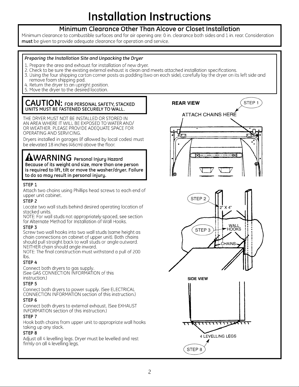
STEP 1
Attach two chains using Phillips head screws to each end of
upper unit cabinet.
STEP2
Locate two wall studs behind desired operating location of
stacked units.
NOTE:Forwall studs not appropriately spaced, seesection
for Alternate Method for Installation of Wall Hooks.
STEP3
Screw two wall hooks into two wall studs (same height as
chain connections on cabinet of upper unit). Both chains
should pull straight back to wall studs or angle outward.
NEITHERchain should angle inward.
NOTE:Thefinal construction must withstand a pull of 200
Ibs.
STEP4
Connect both dryers to gas supply.
(SeeGASCONNECTIONINFORMATIONof this
instruction.)
STEPS
Connect both dryers to power supply. (SeeELECTRICAL
CONNECTIONINFORMATIONsection of this instruction.)
STEP6
Connect both dryers to external exhaust. (See EXHAUST
INFORMATIONsection of this instruction.)
STEP7
Hook both chains from upper unit to appropriate wall hooks
taking up any slack.
STEP8
Adjust all 4 levelling legs.Dryer must be levelled and rest
firmly on all 4 levelling legs.
I
REAR VIEW
ATTACH CHAINS HERE
7
q C7 IC ]7
STEP 2
\
;IDE VIEW
4 LEVELLING LEGS
Page 3

Installation Instructions
Alternate Method for Installation of Wall Hooks
STEP1
If wall studs ore not correctly spaced or centered behind upper unit, it
may be necessary to attach a horizontal 2" x 4" board to the existing wall.
STEP2
Attach wall hooks in approximate position of two chains of upper unit so
each chain pulls straight back to wall.
NOTE:Ifwall isconcrete or block, drill holes and use appropriate wall
anchors. The final construction must withstand a pull of 200 Ibs.
r_ WALL STUDS
r_ ,=i
i
[] PREPARING FOR INSTALLATION OF
NEW DRYER
TIP:Install your dryer before installing your washer.
This will allow better access when installing dryer exhaust.
DISCONNECTING_ GAS
TURNGAS _ DISCONNECTAND DISCARDOLD
SHUT-OFF I¢_-_ FLEXIBLEGASCONNECTORAND _m_-i/%-_
VALVETOTHE _,"-t_ _ OLD DUCTINGMATERIAL.
APPROVEDFLEXIBLEGASLINE
CONNECTORAND ULAPPROVED
TRANSITIONDUCT.
WARNING - NEVERREUSE
OLD FLEXIBLE CONNECTORS.
The use of old flexible connectors can cause leaks
and personal injury. Always use new flexible
connectors when installing gas appliances.
REMOVING LINT FROM WALL EXHAUST
OPENING
• Remove and discord existing plastic or metal foil
transition duct and replace with ULlisted transition duct.
I-_ GAS REQUIREMENTS
,A WARNING
• Installation must conform to local codes and
ordinances,or intheir absence, the NATIONALFUELGAS
CODE,ANSIZ223.
• This gas dryer isequipped with a Valve & Burner
Assembly for useonly with natural gas. Using conversion
kit WE25X0217,your local service organization can
convert this dryer for use with propane (LP)gas. ALL
CONVERSIONSMUSTBEMADEBYPROPERLYTRAINED
AND QUALIFIEDPERSONNELAND IN ACCORDANCEWITH
LOCALCODESAND ORDINANCEREQUIREMENTS.
• The dryer must be disconnected from the gas supply
piping system during any pressure testing of that sys-
tem ata test pressure in excess of 0.5 PSI(3.4 KPa).
• The dryer must be isolated from the gas supply piping
system by closing the equipment shut-off valve during
any pressure testing of the gas supply piping of test
pressure equal to or lessthan 0.5 PSI(3.4 KPa).
DRYER GAS SUPPLY CONNECTION
2"
WALL
INTERNALDUCT
OPENING i- HOODDAMPEROPENS
• TILTTHE DRYERSIDEWAYS AND REMOVETHE FOAM
SHIPPING PADS BY PULLING ATTHE SIDES AND
BREAKING THEM AWAY FROM THE DRYER LEGS. BE SURE
TO REMOVE ALL OF THE FOAM PIECESAROUND THE
LEGS.
CHECKTHATEXHAUSE
ANDCLOSESFREELY.
A 2-5/8"
" 3/8" NPT IVlALETHREADGASSUPPLY
NOTE:Add to vertical dimension
the distance between cabinet
bottom to floor.
GAS SUPPLY
• A 1/8 in. National PipeTaper thread plugged tapping,
accessible for test gauge connection, must be installed
immediately upstream of the gas supply connection to
the dryer. Contact your local gas utility should you have
questions on the installation of the plugged tapping.
• Supply line isto be 1/2 in.rigid pipe and equipped with
an accessible shut-off within 6 ft. of,and in the same
room with the dryer.
• Use pipe thread sealer compound appropriate for
natural or LPgas or use Teflon tape.
• You must use with this dryer aflexible metal connector
(listed connector ANSIZ21.24 / CSA6.10). The length of
the connect shall not exceed 3 ft.
• Connectflexible metal connector to dryer and gassupply.
• Open shut-off valve.
Page 4

Installation Instructions
I_ RECONNECTING GAS
Listed connector ANSI Z2]_.24 / CSA 6.!0
1/8" NPTPIPE
NEWMETAL GAS
FLEXIBLEGAS INLETPRESSURE
LINECONNECTOR
ADAPTER SHUT-OFF
3/8" NPT VALVE
ELBOW
ITEMSNOT SUPPLIED AT LEAST1/2"
NOTE:The connector and fittings are designed for use
only on the original installation and are not to be reused
for another appliance or at another location. Keepflare
end of adaptor free of grease, oil and thread sealant.
PLUGFOR
__ PIPESIZE
I
APPLYPIPECOMPOUND
TOALL MALETHREADS.
CAUTION: Use adaptors as shown. Connector
nuts must not be connected directly to pipe threads.
APPLYPIPECOMPOUND
TOTHEADAPTERAND
DRYERGASINLET.
Tightentheflexible
gaslineusingtwo
adjustablewrenches.
Tighten all connections using two adjustable
wrenches. Do not over torque gas connections!
[] LEAK TEST
_ZlWARNING- NEVER USE AN OPEN
FLAME TO TEST FOR GAS LEAKS.
GASVALVE.
OPEN
Check all connections for leaks with soapy solution or
equivalent. Apply soap solution. Leak test solution must
not contain ammonia which could cause damage to the
brass fittings. If leaks are found, close valve, retighten the
joint, and repeat the soap test.
Page 5

Installation Instructions
I-_ EXHAUST INFORMATION
- WARNING - TO REDUCE THE RISK
OF FIRE OR PERSONAL INJURY:
•This clothes dryer must be exhausted to the outdoors.
• Use only 4" rigid metal ducting for home exhaust duct.
• Use only 4" rigid metal or UL-listed flexible metal (semi-
rigid or foil-type) duct to connect the dryer to the home
exhaust duct. It must be installed in accordance with
these instructions and local codes.
• Do not terminate exhaust in o chimney, o wall, o ceiling,
gas vent, crawl space, attic, under on enclosed floor,
or in any other concealed space of o building. The
accumulated lint could create o potential fire hazard.
• Never terminate the exhaust into o common duct with
o kitchen exhaust system. A combination of grease and
lint creates o potential fire hazard.
• Do not use duct longer than specified in the exhaust
length table. Longer ducts con accumulate lint, creating
o potential fire hazard.
• Never install o screen in or over the exhaust duct. This
will cause lint to accumulate, creating o potential fire
hazard.
• Do not assemble ductwork with any fasteners that
extend into the duct. These fasteners con accumulate
lint, creating o potential fire hazard.
• Do not obstruct incoming or exhausted air.
• Provide on access for inspection and cleaning of the
exhaust system, especially at turns and joints. Exhaust
systemshall beinspectedand cleanedat leastonceo year.
• In special installations, it may benecessary to connect
the dryer to the house vent using o flexible metal (foil-
type) duct. A UL-listed flexible metal (foil-type) duct
may be used ONLYin installations where rigid metal or
flexible metal (semi-rigid) ducting cannot be used AND
where o 4" diameter con be maintained throughout
the entire length of the transition duct. In Canada and
in the United States, only the flexible metal (foil-type)
ducts that comply with the "Outline for Clothes Dryer
Transition Duct Subject 2158A" shall be used.
EXHAUST LENGTH
The MAXIMUM ALLOWABLEduct length and number of
bends of the exhaust system depends upon the type of
duct, number of turns, the type of exhaust hood (wall cap),
and oil conditions noted below. The maximum duct length
for rigid metal duct is shown in the table below.
RECOMMENDEDMAXIMUM LENGTH
Exhaust Hood Types
Recommended
0
1
No. of 90° Elbows
2
More than two 90°turns isnot recommended. Thetotal
length of flexible metal duct shall not exceed 8 ft. (2./4m).In
Canada and in the United States, the required exhaust duct
diameter is4" (102 mm).
RigidMetal RigidMetal
45 ft. 30ft.
35ft. 20ft.
25ft. 10ft.
Useonlyfor short
run installations
_," DIA,
[] EXHAUST CONNECTION
WARNING - BEFOREPERFORMING
THIS EXHAUST INSTALLATION, BESURETO
DISCONNECTTHEDRYERFROMITSELECTRICAL
SUPPLY.PROTECTYOUR HANDS AND ARMS
FROMSHARPEDGESWHEN WORKING INSIDE
THE CABINET. BE SURE TO WEAR GLOVES.
The dryers comes ready for rear exhausting. Units hove
separate exhausts.
REAR EXHAUST LOCATION
NOTE:Add
to vertical
dimension
the distance
between
cabinet
bottom to
3/4"
EXHAUST SYSTEM CHECK LIST
HOOD ORWALL CAP
• Terminate in o manner to prevent back drafts or entry of
birds or other wildlife.
• Termination should present minimal resistance to
the exhaust air flow and should require little or no
maintenance to prevent clogging.
• Never install o screen in or over the exhaust duct. This
could cause lint build up.
• Wall cops must be installed at least 12 in.above ground
levelor anyother obstruction with the opening pointeddown.
SEPARATIONOF TURNS
For best performance, separate all turns by at least 4 ft.
of straight duct, including distance between last turn and
exhaust hood (wall cap). If two turns must be closer than 3
ft., deduct 10 ft. from the maximum lengths shown in the
table for each occurrence.
TURNS OTHERTHAN 90°
• One turn of 45oor less may be ignored.
• Two 450 turns should be treated us one 900 turn.
• Each turn over 450 should be treated as one 900 turn.
SEALINGOFJOINTS
• All joints should be tight to avoid leaks. The mole end of
each section of duct must point away from the dryer.
• The duct shall not be assembled with screws or other
fastening means that extend into the duct and catch lint.
• Duct joints con be mode air and moisture-tight by
wrapping the overlapped joints with duct tape.
• Horizontal runs should slopedown toward the outdoors
1/4 inch per foot.
INSULATION
Duct work that runs through on unheated urea or is
near air conditioning should be insulated to reduce
condensation and lint build-up.
NOTE:Never install screen inside exhaust duct.
floor surface.
Page 6

Installation Instructions
161EXHAUST CONNECTION CONT.
THIS DRYER COMES READY FOR REAR
EXHAUSTING. IF SPACE IS LIMITED, USE
THESE INSTRUCTIONS TO EXHAUST
DIRECTLY FROM THE LEFT SIDE OR
BOTTOM OF THE CABINET. NOTE: This
drger cannot be exhausted to the right
side.
• Never use flexible duct inside dryer.
• Detach and remove the bottom or left side knockout as
desired.
• Remove the screw inside the dryer exhaust duct and save.
Pullthe duct out of the dryer. Protect sharp edgesaround the
knockout and exhaust opening with the tape.
• Cut the duct as shown. Keep portion A.
FIXING
• Through the rear opening, locate the tab in the middle of
the appliance base. Lift the tab to about 45° using a flat
screwdriver.
• Reconnect and secure the cut portion (A)of the duct
to the blower housing. Make sure that the fixing hole is
aligned with the tab in the base. Usethe screw of item
2 to secure the duct in place through the tab on the
appliance base.
I-7-1ALCOVE OR CLOSET INSTALLATION
•If your dryer is approved for installation in an alcove or
closet, it will be stated on a label on the dryer back.
•The dryer MUST be vented to the outdoors. See the
EXHAUSTINFORMATIONsection.
• Minimum clearance from combustible surfaces and non-
combustible surfaces for air intake purposes is:
0 in. either side
3 in.front and rear
NOTE: WHEN THE EXHAUST DUCT IS LOCATED AT THE
REAR OF THE DRYER, MINIMUM CLEARANCE FROM THE
WALL IS 5.5 in.
• Minimum vertical space from floor to overhead cabinets,
ceiling, etc. is 88 in.
•Closet doors must be Iouvered or otherwise ventilated
and must contain a minimum of 60 sq. in. of open area
equally distributed. If the closet contains both a washer
and a dryer, doors must contain a minimum of 120 sq. in.
of open area equally distributed.
•The closet should be vented to the outdoors to prevent
gas pocketing in case of a gas leak in the supply line.
• No other fuel-burning appliance shall be installed in the
same closet with the dryer.
Only metal duct
BLOWER inside the dryer
HOUSING BASE TAB cabinet
LOCATION
9 " CUT (UNDER EXHAUST
PORTION DUCT)
11 1/4 " BACK OF
• Use standard metal elbows and duct to complete
exhaust system. Insert standard elbow and ducts
through rear and side or bottom openings.
• Cover the opening at the back with the plate (Kit
WE1M454) available from your Local Service Provider.
may be used
SIDE PANEL
-ZILWARNING-NEVER LEAVE THE
BACK OPENING WITHOUT THE PLATE.
PARTS AVAILABLE FROM LOCAL SERVICE
ORGANIZATION
• Rigid Metal Duct Components
WX8X63 4" X 1' Duct
WX8X64 4" x 2' Duct
WX8X51 4" Elbow
WX8X59 Aluminum Hood
• Flexible Metal Duct Components
WX08X10077 4" dia. Flexible Metal (Semi-Rigid)
UL-Listed Transition Duct (includes 2 elbows)
Page 7

Installation Instructions
[_ELECTRICAL CONNECTION INFORMATION
WARNING - TO REDUCE THE RISK
OF FIRE, ELECTRICAL SHOCK, AND
PERSONAL INJURY:
• DO NOT USE AN EXTENSION CORD
OR AN ADAPTER PLUG WITH THIS
APPLIANCE.
Dryer must be electrically grounded in accordance
with local codes and ordinances, or in the absence
of local codes, in accordance with the NATIONAL
ELECTRICALCODE,ANSI/NFPANO.70.
ELECTRICAL REQUIREMENTS
This appliance must be supplied with 120V,60Hz, and
connected to an individual, properlg grounded branch
circuit, protected bg a iS- or 20-amp circuit breaker or
time delag fuse. If electrical supplg provided does not
meet the above specifications, it is recommended that
a licensed electrician install an approved outlet.
WARNING - THISDRYERIS
EQUIPPED WITH A THREE-PRONG
(GROUNDING) PLUG FOR YOUR
PROTECTION AGAINST SHOCK HAZARD
AND SHOULD BE PLUGGED DIRECTLY
INTO AN INDIVIDUAL, PROPERLY
GROUNDED THREE-PRONG RECEPTACLE.
DO NOT CUT OR REMOVE THE
GROUNDING PRONG FROM THIS PLUG.
ENSURE PROPER GROUND EXISTS BEFORE USE
ADJUSTING FOR ELEVATION
• Gas clothes dryers input ratings are based on sea level
operation and need not be adjusted for operation at or
below 2000 ft. elevation.
For operation at elevations above 2000 ft., input ratings
should be reduced at a rate of 4 percent for each 1000 ft.
above sea level.
• Installation must conform to localcodes and ordinances or,
in their absence,the NATIONALFUELGASCODE,ANSIZ223.
NOTE TO INSTALLER
AFTERINSTALLATIONCHECKTHE FOLLOWING:
[] EXHAUST DUCT - Must meet specs in the EXHAUST
INFORMATION section.
[] GROUNDING- Dryermust beproperlygroundedto conformto
localcodesand ordinancerequirements.
[] OPERATION- Turndryeronand checkfor heat.
[] Handcustomerthe Owner's Manual- Giveinstructionson
operatingthe dryer - Answerany questions.
[] GivetheseInstallationInstructionstothe customen
CARE AND CLEANING
USERMAINTENANCEINSTRUCTIONS
The Drum. The drum is rust-resistant and requires
no special care.
The Exterior. Wipe off any spills or washing compounds.
Wipe or dust with damp cloth. Try not to strike the surface
with sharp objects.
The Lint Filter. Wipe lint filter before every use. Periodically
lint filter should beremoved and suction hose from vacuum
cleaner should be inserted into the opening.
Drger Exhaust. Inspect and clean the dryer exhaust
ducting at least once a year.
Do not obstruct the flow of combustion and ventilating air.
The air intake is located on rear of dryer.
Keep dryer area clear and free from combustible materials,
gasoline and other flammable vapors and liquids.
To store drger. Forshort period of time, disconnect power
supply and clean lint filter.
Do not install or store dryer where it will be exposed to the
weather.
EXTERNAL GROUND (IF REQUIRED)
An external ground wire, (not provided), which meets local
codes, may beadded byattaching to the green ground
screw on the rear of the dryer, and to a grounded metal
cold water pipe or other established ground.
ATTACH GROUND WIRE (OBTAIN
LOCALLY)TO EACH DRYER
CAUTION:
• Dryer control panel and finishes may be damaged by
some laundry pre-treatment soil and stain remover
products if such products are sprayed on or have direct
contact with the dryer.
Apply these pre-treatment products away from the
dryer. The fabric may then bewashed and dried
normally. Damage to your dryer caused by pretreatment
products is not covered by your Warranty.
REGISTERYOURNEW APPLIANCETO RECEIVEANY
IMPORTANTPRODUCTNOTIFICATIONS.
Please go to www.GEAppliunces.com or mail in the
Product Registration Card.
Forquestions on installation, coil: 800.626.2000 (US)or
800-561-3344 (Canada).
I
Page 8

Installation Instructions
 Loading...