

Page 1
, WA I G -RiSKOFFIRE
= To reduce the risk of severe injuryor death, follow' all installation instructions.
Clothes dryer installation must be performed by a qualified installer.
install the clothes dryer according to these instructions and in accordance with local codes. In the absence of local
codes, installation must comply with National Fuel Gas Code, ANSIZ223.1/NFPA 54 or the Canadian Natural Gas
and Propane installation Code, CSA B149.1.
California Safe Drinking Water and Toxic Enforcement Act
This act requiresthe governor of California to publish a list of substances known tothe state to cause cancer, birthdefects or
other reproductive harm and requiresbusinesses to warn customers of potential exposure to such substances. Gas appliances
can cause minorexposure tofour of these substances, namely benzene, carbon monoxide, formaldehyde and soot, caused
primarily by the incomplete combustion of natural gas or LP fuels. Properly adjusted dryers will minimize incomplete combustion.
Exposure to these substances can be minimized further by properlyventing the dryer to the outdoors.
This dryer must be exhausted to the outdoors.
Use only 4" rigid metal ducting for exhausting the clothes dryer to the outdoors.
• DO NOT install a clothes dryer with flexible plastic ducting materials, if flexible metal (semi-rigid or foil-type) duct is
installed, it must be UL listed and installed in accordance with these instructionsand local codes. Flexible venting
materials are known to collapse, be easily crushed, and trap lint. These conditions will obstruct dryer airflow and
increase the risk of fire.
• Do not install or store this appliance in any location where itcould be exposed to water and or weather.
= Save these instructions. (installers: Be sure to leave these instructionswith the customer).
BEFORE YOU BEGIN- Readthe_einstructions
completely and carefully
• important - Save these instructionsfor local inspector's use.
• important- Observe all governing codes and ordinances.
• Note to Installer
- Be sure to leave these instructions with the customer.
• Note to Customer
- Keep these instructions for local inspector's use.
• Before the old dryer is removed from service or discarded, remove
the dryer door.
• inspect the dryer exhaust outlet and straighten the outlet walls if
they are bent.
• Service information and the wiring diagram are located in the
control console.
• Do not allow children on or in the appliance. Close supervision is
necessary when the appliance is used near children.
• install the dryer where the temperature is above 50°F for satisfactory
operation of the dryer control system.
,_ WARNING: For your safety the information in this manual
must be followed to minimize the risk of fire or explosion or to
prevent property damage, personal injury or death.
- Do not store or use gasoline or other flammable vapors and
liquids in the vicinity of this or any other appliance.
=WHATTO DO IFYOU SMELL GAS
• Do not try to light any appliance.
, Do not touch
in your building.
, Clear the room, building or area of all occupants.
Immediately call your gas supplier from a neighbor's
phone. Follow the gas supplier's instructions.
If you cannot reach your gas supplier, call the fire dep't.
- Installation and service must be performed by a qualified
installer, service agency, or the gas supplier.
500A436P004
Pub.# 31-16223
any electrical switch; do not use any phone
Tools and Materials
you will need
[] Slip joint pliers, 8" pipe wrench,
10" adjustable wrenches (x2),
[] Screwdrivers (slotted or phillips head)
[] Chains (x2)
[] 2" x 4" studs
[] Wall hoods
[] 4" diameter rigid metal duct, duct clamps,
elbows and exhaust hood.
[] Flexible gas connector
[] Pipe compound
[] Soap solution for leak detection
[] Basic safety protection such as safety
goggles, gloves and arm protection are
recommended.
The ANSI Z21.5.1 standard requires the follow-
ing safety cautions be posted and displayed in a
3rominent location:
a. Instructions to be followed in the event
the user smells gas. The information
to be posted shall be obtained by
consulting with the local gas supplier.
b.This note:
FOR YOUR SAFETY
DONOT STOREOR USEGASOLINEOR
OTHER FLAMMABLE VAPORS AND LIQUIDS
IN THE VICINITY OF THIS OR ANY OTHER
APPLIANCE.
In the state of Massachusetts, installa=
tion must be performed by a qualified or
licensed contractor, plumber, or gas
fitter qualified or licensed by the state.
NOTE: Service of this dryer must be
performed by a qualified service agency.
Page 2
iNSTALLATiON
Preparing the installation Site and Unpacking the Dryer
1.Prepare the area and exhaust for installation of the new' dryer.
2.Check to be sure that the existing external exhaust is clean and that it meets attached installation specifications.
&Using the four shipping carton corner posts as padding (two on each side), carefully lay the dryer on its left side
and remove foam shipping pad.
4. Return the dryer to an upright position.
5.Move the dryer to the desired location.
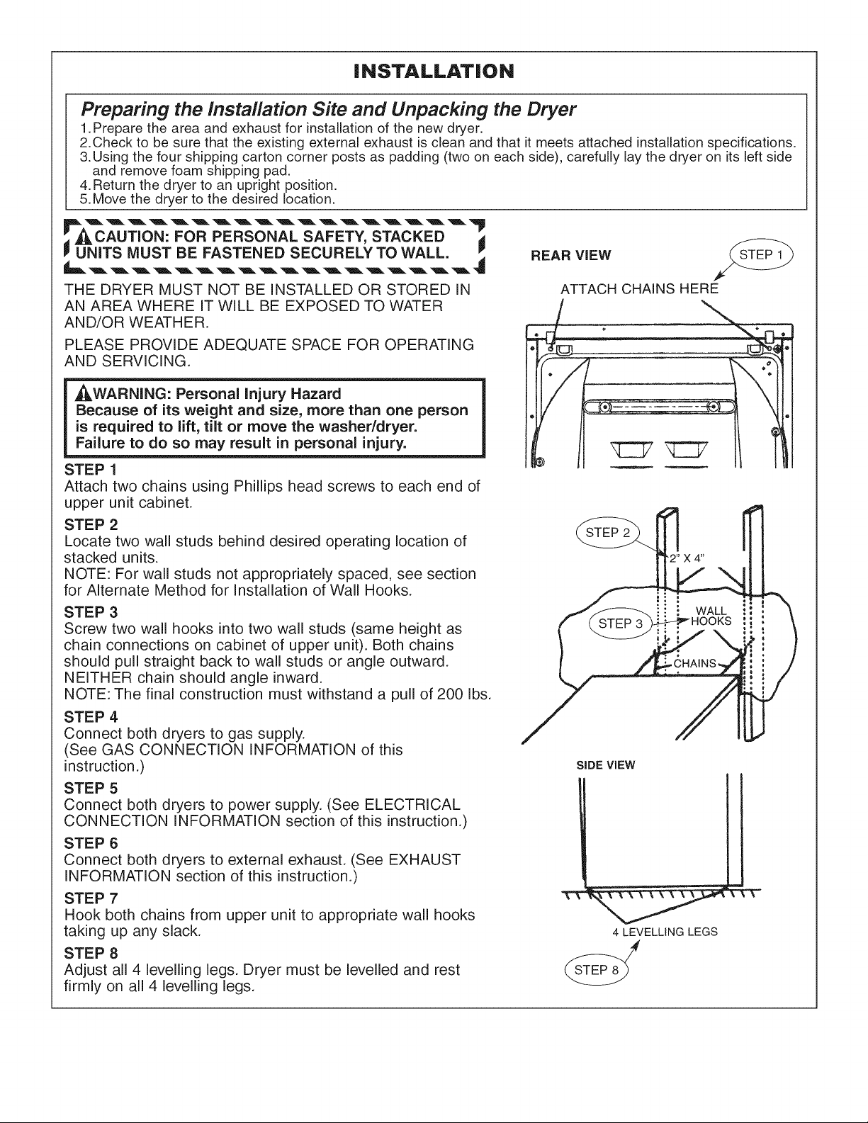
CAUTION: FOR PERSONAL SAFETY, STACKED
iTS MUST BE FASTENED SECURELY TO WALL. r
REAR ViEW
THE DRYER MUST NOT BE iNSTALLED OR STORED iN
AN AREA WHERE iT WILL BE EXPOSED TO VVATER
AN D/O R WEATH ER.
PLEASE PROVIDE ADEQUATE SPACE FOR OPERATING
AND SERVICING.
_WARNING: Personal injury Hazard
Because of its weight and size, more than one person
is required to lift, tilt or move the washer/dryer.
Failure to do so may result in personal injury.
STEP 1
Attach two chains using Phillips head screws to each end of
upper unit cabinet.
STEP 2
Locate two wall studs behind desired operating location of
stacked units.
NOTE: For wall studs not appropriately spaced, see section
for Alternate Method for Installation of Wall Hooks.
STEP 3
Screw two wall hooks into two wall studs (same height as
chain connections on cabinet of upper unit). Both chains
should pull straight back to wall studs or angle outward.
NEITHER chain should angle inward.
NOTE: The final construction must withstand a pull of 200 Ibs.
STEP 4
Connect both dryers to gas supply.
(See GAS CONNECTION INFORMATION of this
instruction.)
STEP 5
Connect both dryers to power supply. (See ELECTRICAL
CONNECTION INFORMATION section of this instruction.)
STEP 6
Connect both dryers to external exhaust. (See EXHAUST
INFORMATION section of this instruction.)
STEP 7
Hook both chains from upper unit to appropriate wall hooks
taking up any slack.
STEP 8
Adjust all 4 levelling legs. Dryer must be levelled and rest
firmly on all 4 levelling legs.
ATTACH CHAINS HERE
STEP 2
SIDE VIEW
4 LEVELLING LEGS
Page 3
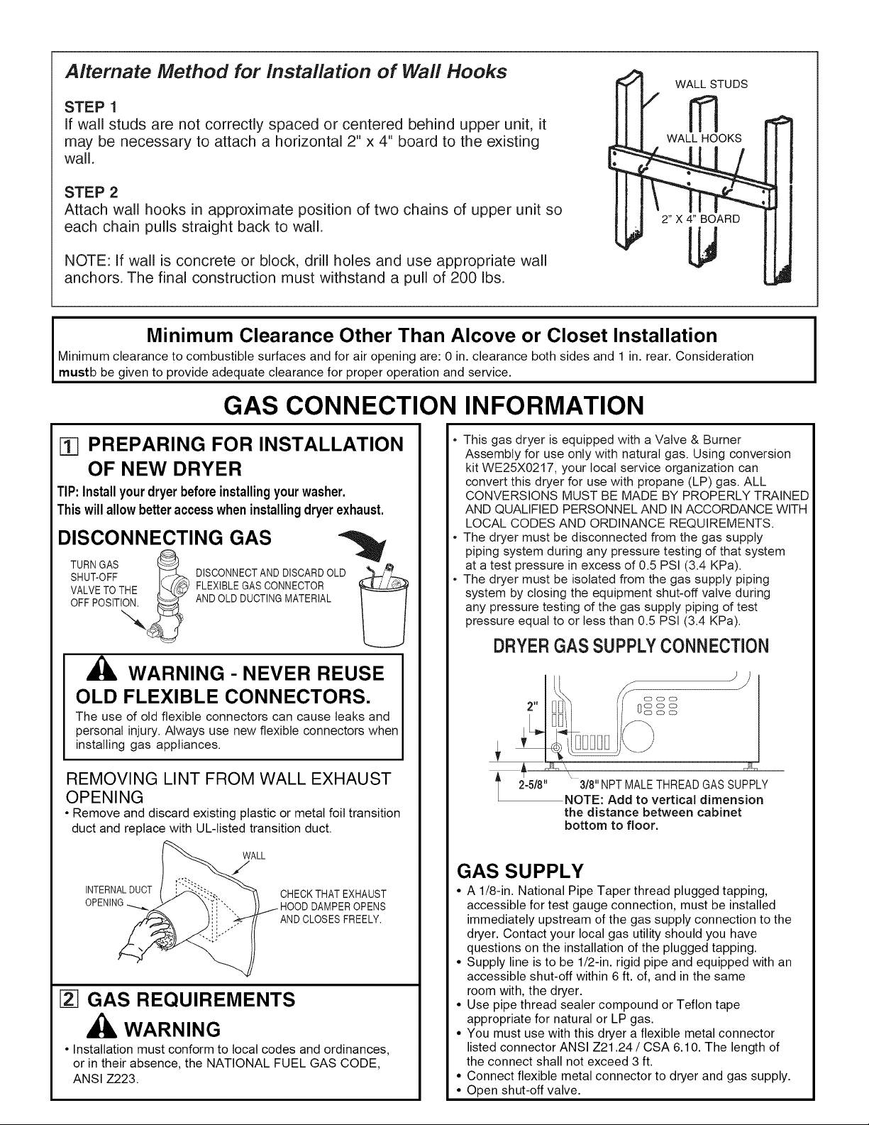
Alternate Method for Installation of Wall Hooks
STEP 1
If wall studs are not correctly spaced or centered behind upper unit, it
may be necessary to attach a horizontal 2" x 4" board to the existing
wall.
STEP 2
Attach wall hooks in approximate position of two chains of upper unit so
each chain pulls straight back to wall.
NOTE: If wall is concrete or block, drill holes and use appropriate wall
anchors. The final construction must withstand a pull of 200 Ibs.
E
WAr_TUDS
Minimum Clearance Other Than Alcove or Closet Installation
Minimum clearance to combustible surfaces and for air opening are: 0 in. clearance both sides and 1 in. rear. Consideration
mustb be given to provide adequate clearance for proper operation and service.
GAS CONNECTION INFORMATION
[i] PREPARING FOR INSTALLATION
OF NEW DRYER
TIP:Installyourdryerbeforeinstallingyourwasher.
Thiswill allowbetteraccesswheninstallingdryerexhaust.
DISCONNECTING GAS
SHUT-OFF
VALVETOTHE
OFFPOSITION.
TURNGAS
",.,.
DISCONNECTANDDISCARDOLD _
FLEXIBLEGASCONNECTOR
ANDOLDDUCTINGMATERIAL
U
• This gas dryer is equipped with a Valve & Burner
Assembly for use only with natural gas. Using conversion
kit WE25X0217, your local service organization can
convert this dryer for use with propane (LP) gas. ALL
CONVERSIONS MUST BE MADE BY PROPERLY TRAINED
AND QUALIFIED PERSONNEL AND IN ACCORDANCE WITH
LOCAL CODES AND ORDINANCE REQUIREMENTS.
• The dryer must be disconnected from the gas supply
piping system during any pressure testing of that system
at a test pressure in excess of 0.5 PSI (3.4 KPa).
• The dryer must be isolated from the gas supply piping
system by closing the equipment shut-off valve during
any pressure testing of the gas supply piping of test
pressure equal to or less than 0.5 PSI (3.4 KPa).
DRYERGASSUPPLYCONNECTION
I
J
_ WARNING - NEVER REUSE
OLD FLEXIBLE CONNECTORS.
The use of old flexible connectors can cause leaks and
personal injury. Always use new flexible connectors when
installing gas appliances.
REMOVING LINT FROM WALL EXHAUST
OPENING
• Remove and discard existing plastic or metal foil transition
duct and replace with UL-listed transition duct.
WALL
INTERNALDUCT
CHECKTHATEXHAUST
HOODDAMPEROPENS
ANDCLOSESFREELY.
[_ GAS REQUIREMENTS
WARNING
• Installation must conform to local codes and ordinances,
or in their absence, the NATIONAL FUEL GAS CODE,
ANSI Z223.
,)
/
211 _ o o o
_ _,,,
2-5/8" 3/8"NPTMALETHREADGASSUPPLY
t
NOTE: Add to vertical dimension
the distance between cabinet
bottom to floor.
GAS SUPPLY
• A 1/8-in. National Pipe Taper thread plugged tapping,
accessible for test gauge connection, must be installed
immediately upstream of the gas supply connection to the
dryer. Contact your local gas utility should you have
questions on the installation of the plugged tapping.
• Supply line is to be 1/2-in. rigid pipe and equipped with an
accessible shut-off within 6 ft. of, and inthe same
room with, the dryer.
• Use pipe thread sealer compound or Teflon tape
appropriate for natural or LP gas.
• You must use with this dryer a flexible metal connector
listed connector ANSI Z21.24 / CSA 6.10. The length of
the connect shall not exceed 3 ft.
• Connect flexible metal connector to dryer and gas supply.
• Open shut-off valve.
Page 4

GAS CONNECTION
m
RECONNECTINGGAS
Listed connector ANSI Z21.24 / CSA 6.10
118" NPT PIPE
NEWMETAL PLUG FOR
FLEXIBLEGAS INLET PRESSURE
LINECONNECTOR
ADAPTER
318" NPT
ELBOW
ITEMSNOT SUPPLIED AT LEAST 1/2"
Note:The connector and fittings ore designed for useonly
on the original installation and are not to be reusedfor
another appliance or at another location. Keepflare end of
adaptor free of grease,oil and thread sealant.
Caution: Useadapters as shown. Connector nuts must not
be connected directly to pipe threads.
GAS
SHUT-OFF
PIPE SIZE
INFORMATION (continued)
APPLYPiPECOMPOUND
TOALL MALETHREADS.
/
Tighten the flexible
gas line using two
adjustable wrenches.
APPLYPIPECOMPOUND
TOTHEADAPTERAND
DRYERGAS INLET.
Tighten all connections using two adjustable wrenches.
Do not overtorque gas connections!
[] LEAKTEST
A_, WARNING- NEVERUSEANOPEN
FLAMETOTEST FORGAS LEAKS.
OPEN
GASVALVE.
Check olt connections for leaks with soapg solution or equivalent.
Applg soap solution. Leak test solution must not contain ammo-
nia which could cause damage to the brass fittings. If leaks are
found, dose valve, retighten the joint, and repeat the soap test.
Page 5

EXHAUST INFORMATION
l I Illlll Illll II_ll_
WARNING - TO REDUCE THE RiSK OF
FiRE OR PERSONAL iNJURY: r
- This clothes dryer must be exhausted to the outdoors.
- Use only 4" rigid metal ducting for the home exhaust
duct.
- Use only 4" rigid metal or UL-listed flexible metal
(semi-rigid or foil-type) duct to connect the dryer to
accordance with these instructions and local codes.
I the home exhaust duct. It must be installed in d
- Do not terminate exhaust in a chimney, a wall, a ceil-
floor, or in any other concealed space of a building.
I ing, gas vent, crawl space, attic, under an enclosed
The accumulated lint could create a fire hazard.
with a kitchen exhaust system. A combination of
- Never terminate the exhaust into a common duct
grease and lint creates a potential fire hazard.
- o not use duct longer than specified in the exhaust
length table. Longer ducts can accumulate lint,
creating a potential fire hazard.
- ever install a screen in or over the exhaust duct.
This will cause lint to accumulate, creating a poten-
tial fire hazard.
- Do not assemble ductwork with any fasteners that
ate lint, creating a potential fire hazard.
I extend into the duct. These fasteners can accumul-
- Do not obstruct incoming or exhausted air.
- rovide an access for inspection and cleaning of the
exhaust system, especially at turns and joints.
Exhaust system shall be inspected and cleaned at
least once a year.
the dryer to the house vent using a flexible metal (foil-
- n special installations, it may be necessary to connect
type) duct. A UL-listed flexible metal (foil4ype) duct
REAR EXHAUST LOCATION
The dryers come ready for rear exhausting. Units
have separate exhausts.
J i_i_/_ _ dNOenTE:siAodlt;vdiedt_Cale
' !! II iJli'i' I- ---..........................................._..I _1 between cabinetbottomto
;13/4 " _ ........................... '0 .... rface.
EXHAUST SYSTEM CHECK LIST
HOOD OR WALL CAP
,, Terminate in a manner to prevent back drafts or
entry of birds or other wildlife.
,, Termination should present minimal resistance
to the exhaust air flow and should require little
or no maintenance to prevent clogging.
,, Wall caps must be installed at least 12" above
ground level or any other obstruction with the
opening pointed down.
SEPARATION OF TURNS
Separate all turns by at least 3 ft. of straight duct,
including distance between last turn and
dampered wall cap. If two turns must be closer
than 3 ft., deduct 10 ft. from the maximum
lengths shown in the table for each occurrence.
TURNS OTHER THAN 90 °
flexible metal (semi-rigid) ducting cannot be used AND
I may be used ONLY in installations where rigid metal or d
where a 4" diameter can be maintained throughout the
entire length of the transition duct. In Canada and in _
, the United States, only the,!lexible metal (foil-type)
| ducts that comply with the Outline for Clothes Dryer
,,_'_,_'_mm,_l_,_m'_'_m,_,__Transition Duct Subject 2158A" shall be used. ,_
EXHAUST LENGTH
The MAXIMUM ALLOWABLE duct length and number of
bends of the exhaust system depends upon the type of duct,
number of turns, the type of exhaust hood (wall cap), and all
conditions note below. The maximum allowable length for
rigid metal duct is shown inthe
PREFERRED
table below. More than two 90 °
turns is not recommended. The
total length of flexible metal duct
shall not exceed 8 ft.(2.4 m). In
Canada and in the United States,
the required exhaust duct diameter
is 4in (102mm). NUMBER
OF 90°
TURNS
RIGID METAL DUCT 0
4 in. 2 1/in.
MAXIMUM LENGTH
EXHAUST
- HOOD TYPE -
A B
45 ft. 30 ft.
35 ft. 2O ft.
4" DIAMETER 2
25 ft. 10 ft.
,, One turn of 45 ° or less may be ignored.
,, Two 45 ° turns should be treated as one 90 °.
,, Each turn over 45 ° should be treated as one 90 °.
I
SEALING OF JOINTS
All joints should be tight to avoid leaks. The male
end of each section of duct must point away
from the dryer.
Do not assemble the duct work with fasteners
that extend into the duct. They will serve as a
collection point for lint.
Duct joints can be made air and moisture-tight
by wrapping the overlapped joints with duct tape.
INSULATION
Duct work which runs through an unheated area
or is near an air conditioning duct should be
insulated to reduce condensation and lint build up
and be sloped down toward outdoors.
NOTE: Never install screen inside exhaust duct.
Page 6

EXHAUST iNFORMATiON {continued)
STEPS TO CHANGE DRYER TO LEFT SIDE OR BOTTOM EXHAUST DIRECTLY ON CABINET
NOTE: This dryer can not be exhausted to the right side.
WARNING: Protect your hands and arms from sharp
edges when working inside dryer cabinet.
= Never use flexible duct inside dryer.
,, Detach and remove the desired knockout.
,, Remove the screw inside the dryer exhaust duct end.
Keep the screw for step 5. Pull on the duct to remove
it.
,, Cut the duct as shown. Keep portion A.
,, Through the rear opening, locate the tab in the middle
of the appliance base. Lift the tab to about 45° using a
flat screwdriver.
,, Reconnect and secure the cut portion (A) of the duct
to the blower housing. Make sure that the fixing hole is
aligned with the tab in the base. Use the screw of item
2 to secure the duct in place through the tab on the
appliance base.
,, Use standard metal elbows and duct to complete
exhaust system. Insert standard elbow and ducts
through rear and side or bottom openings.
,, Cover the opening at the back with the plate (Kit
WE1 M454) available from your Local Service Provider.
HOUSING BASE TAB
LOCATION
9 " CUT (UNDER EXHAUST
PORTION
11 1/4 " BACK OF
_-- _ SIDE PANEL
Only metal duct
may be used
inside the dryer
cabinet
i
WARNING: NEVER LEAVE THE BACK OPENING
WITHOUT THE PLATE.
PARTS AVAILABLE FROM LOCAL SERVICE
ORGANiZATiON
,, Rigid Metal Duct Components
WX8X63 4" X 1' Duct
WX8X64 4" x 2' Duct
,, Flexible Metal Duct Components
WX08X10077 4" dia. Flexible Metal (Semi-Rigid)
UL-Listed Transition Duct (includes 2 elbows)
WX8X51 4" Elbow
WX8X59 Aluminum Hood
MiNiMUM CLEARANCES
MINIMUM CLEARANCES FROM COMBUSTIBLE SURFACES AND NON-COMBUSTIBLE SURFACES
FOR AIR INTAKE PURPOSES.
Minimum clearances are - 0" both sides
- 1" at rear
- 88" vertical space from floor to ceiling
Page 7

ELECTRICAL CONNECTION iNFORMATiON
_CAUTION, FOR PERSONAL SAFETY:
DO NOT USE AN EXTENSION CORD OR AN
ADAPTER PLUG WiTH THiS APPLIANCE.
DO NOT, UNDER ANY CIRCUMSTANCES,
CUT OR REMOVE THE THIRD GROUNDING
PRONG FROM THE POWER CORD.
Dryer must be electrically grounded in accordance
with local codes and ordinances, or in the absence
of local codes, in accordance with the NATIONAL
ELECTRICAL CODE, ANSI/NFPA NO. 70-1990.
The electrical diagram is located inside control
panel.
Electrical requirements
,, This appliance must be supplied with 120V, 60
Hz, and connected to an individual, properly
grounded branch circuit, protected by a 15 or 20
amp circuit breaker or time-delay fuse.
if the electric supply
provided does not meet the
above specifications, if is
recommended that a
licensed electrician install an
approved outlet.
External ground (if
REAR VIEW
iNSURE PROPER
GROUND EXISTS
BEFORE USE
required)
An external ground wire, (not
provided), which meets local
codes, may be added by
attaching to the green
ground screw on the rear of
the dryer, and to grounded
metal cold water pipe or
other established ground.
[ _ "ILL "IL "111_ "IL_ I "!IL. "_IL "_IIL "_EL I "qlL I "_lllb_ "qll_ "_
,_CAUTION: Label all wires prior to ,_
disconnection when servicing controls. Wiring F
error can cause improper and dangerous
sOperation. Verify proper operation after |
ervicing. "_
"_llL_ "_mL "_E_ "!IL "IL "_Jm=_lm_ "qlL "IL "_lb= "IL "_lh= "_IL. "IL "1t= "_
ATTACH GROUND WERE TO
EACH DRYER (OBTAIN LOCAL-
LY)
I
CARE AND CLEANING
USER MAINTENANCE iNSTRUCTiONS
The Drum. The drum is rust-resistant and requires
no special care.
The Exterior. Wipe off any spills or washing
compounds. Wipe or dust with damp cloth. Try not
to strike the surface with sharp objects.
The Lint Filter. Wipe lint filter before every use.
Periodically lint filter should be removed and
suction hose from vacuum cleaner should be
inserted into the opening.
Dryer Exhaust. Inspect and clean the dryer
exhaust ducting at least once a year.
Do not obstruct the flow of combustion and
ventilating air. The air intake is located on rear of
dryer.
Keep dryer area clear and free from combustible
materials, gasoline and other flammable vapors
and liquids.
Note to Installer:
After Installation check the following:
[] Exhaust Duct - must meet specs as mentioned
in "Exhaust information" section of this
installation instructions.
[] Grounding - Dryer must be properly grounded to
conform to local codes and ordinance
requirements.
To store dryer. For short period of time, disconnect
power supply and clean lint filter.
Do not install or store dryer where it will be
exposed to the weather.
ACAUTIONS
,, Dryer control panel and finishes may be
damaged by some laundry pre-treatment soil
and stain remover products if such products
are sprayed on or have direct contact with the |
dryer.
Apply these pre-treatment products away from the
dryer. The fabric may then be washed and dried
normally. Damage to your dryer caused by pre-
treatment products is not covered by your warranty.
[] Operation - Turn dryer ON and check for heat.
[] Hand Customer the Use and Care Book - Give
instructions on operating the dryer - answer any
questions.
[] Give these installation instructions to the
customer.
 Loading...