

Page 1
A
WARNING - POTENTIAL FIRE AND SHOCK HAZARD
• Use only rigid metal or flexible metal 4_'diameter ductwork inside the dryer cabinet or for exhausting to
the outside Never use plastic or other combustible ductwork Never use foil or other thin ductwork that
can be easily punctured with a screwdriver or nail
• This appliance must be properly grounded and installed as described in these instructions
Tools you will need
° The dryers must be exhausted to the outside
° Use only metal duct inside dryer cabinet or for exhausting
to outside
WARNING: For your safety the information in
this manual must be followed to minimize the risk
of fire or explosion or to prevent property
damage, personal injury or loss of life.
• Do not store or use gasoline or other
flammable vapors and liquids in the vicinity of
this or any other appliance.
WHAT TO DO IF YOU SMELL GAS
• Do not try to light any appliance.
• Do not touch any electrical switch; do not use
any phone in your building.
, Clear the room, building or area of all
occupants.
• Immediately call your gas supplier from a
neighbor's phone. Follow the gas supplier's
instructions
• if you cannot reach your gas supplier call the
fire department
Installation and service must be performed by a
qualified installer, service agency or the gas
supplier.
The American Gas Association requires the following
safety cautions be posted and displayed in a
a. Instructions to be followed in the event the user
Slip joint pliers
Phillips and flat head screwdrivers
prominent location:
smells gas. The information to be posted shall be
obtained by consulting with the local gas supplier.
b. This note:
FOR YOUR SAFETY
DO NOT STORE OR USE GASOLINE OR
OTHER FLAMMABLE VAPORS AND LIQUIDS
tN THE VICINITY OF THIS
OR ANY OTHER APPLIANCE
500A 187P009
aev _ Pub, NO. 31-1724
Page 2
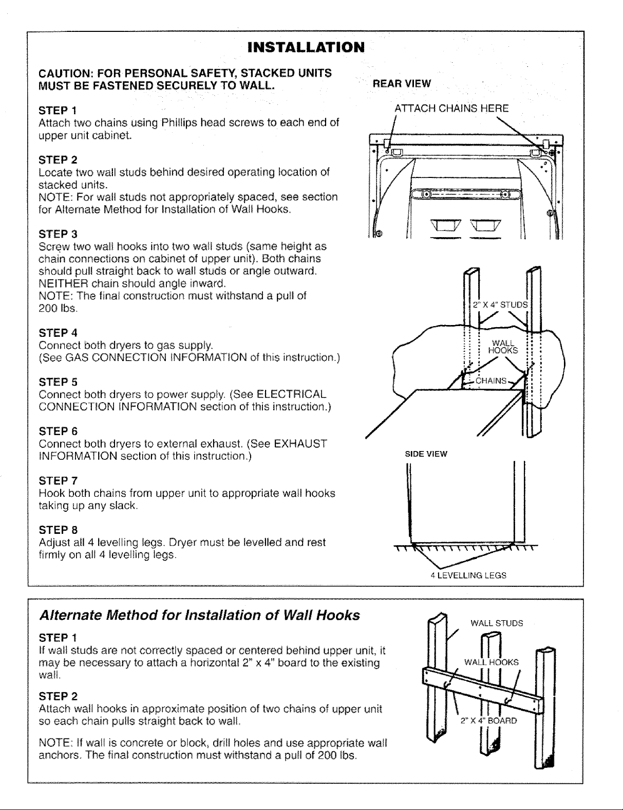
CAUTION: FOR PERSONAL SAFETY, STACKED UNITS
MUST BE FASTENED SECURELY TO WALL.
REAR VIEW
STEP 1
Attach two chains using Phillips head screws to each end of
upper unit cabinet.
STEP 2
Locate two wall studs behind desired operating _ocation of
stacked units.
NOTE: For wall studs not appropriately spaced, see section
for Alternate Method for installation of Wall Hooks.
STEP 3
Screw two wall hooks into two wall studs (same height as
chain connections on cabinet of upper unit). Both chains
should pul! straight back to wall studs or angle outward.
NEITHER chain should angle inward.
NOTE: The final construction must withstand a pull of
200 Ibs.
STEP4
Connect both dryers to gas supply.
(See GAS CONNECTION iNFOR:MATiON of this instruction.)
STEP 5
Connect both dryers to power supply. (See ELECTRICAL
CONNECTION INFORMATION section of this instruction,)
ATTACH CHAINS HERE
o
! '
STEP 6
Connect both dryers to external exhaust. (See EXHAUST
iNFORMATION section of this instruction.)
STEP 7
Hook both chains from upper unit to appropriate walt hooks
taking up any slack.
STEP 8
Adjust all 4 levelling legs. Dryer must be levelled and rest
firmly on alt 4 levelling legs.
/
Alternate Method for Installation of Wall Hooks
STEP 1
if wall studs are not correctly spaced or centered behind upper unit, it
may be necessary, to attach a horizontal 2" x 4" board to the existing
wall.
STEP 2
Attach wall hooks in approximate position of two chains of upper unit
so each chain pulls straight back to wall.
SIDE VIEW
4 LEVELLING LEGS
WALL STUDS
ffl
WALL HOOKS
NOTE: if wall is concrete or b!ock_ ddll holes and use appropriate wall
anchors. The final construction must withstand a puil of 200 Ibs,
Page 3

ELECTRICAL CONNECTION INFORMATION
CAUTIONs FOR PERSONAL SAFETY:
DO NOT USE AN EXTENSION CORD OR AN ADAPTER
PLUG WiTH THIS APPLIANCE,
DO NOT, UNDER ANY C_RCUMSTANCES, CUT OR
REMOVE THE THIRD GROUNDING PRONG FROM THE
POWER CORD,
Dryer must be e_ectficaHy grounded in accordance with
local codes and ordinances, or in the absence of local
codes, in accordance with the NATIONAL ELECTRICAL
CODE, ANSI/NFPA NO. 70-1990
The electrical diagram is located inside control panel
Electrical requirements
. This appliance must be supplied with !20V, 60 Hz, and
connected to an individual, properly grounded branch cir-
cuit, protected by a 15 or 20 amp circuit breaker or time-
delay fuse.
GAS CONNECTION INFORMATION
If the electric supply provided
does not meet the above specifi-
cations, it is recommended that a
licensed electrician install an
approved outlet
INSURE PROPER
GROUND EXISTS
External ground (if required)
An external ground wire, (not prom
vided), which meets local codes, REAR VIEW
may be added by attaching to the ];I "\_. _ LI
green ground screw on the rear ]// "--._.._t__}
of the dryer, and to grounded
metal cold water pipe or other
established ground.
AT3['ACH GROUND W_E TO
_AON ORY£R (OBTAIN LOCALLY}
BEFORE USE
Installation must conform with local codes and ordi-
nances, or in their absence the NATIONAL FUEL GAS
CODE, ANSi 2223 1-1988
GAS BURNER ORIFICE
This gas dryer is equipped with a Valve & Burner
Assembly for use on{y with natural gas. Using a separate
conversion kit your local Service organization can convert
this dryer for use with gases listed on the rating piate.
ALL CONVERSIONS MUST BE MADE BY PROPERLY
TRAINED AND QUALIFIED PERSONNEL, AND iN
ACCORDANCE WITH LOCAL CODE AND ORDINANCE
REQUIREMENTS.
GAS SUPPLY
• Supply line is to be 1/2" rigid pipe, (3/4" copper tubing
may be used if the dryer is operated on Liquefied
Petroleum gas), and equipped with an accessible shut-
off within 6 feet of, and in the same room with the dryer
increase pipe size for runs longer than 20 feet,
• Protection of Dryer During Pressure Test:
- When test pressure is in excess of 1/2 PSiG
(3,45kPa), disconnect dryer and its individual shutoff
valve from gas supply line prior to test
- When test pressure is equal to or less than 1/2 PSIG
(3,45kPa), close the dryer shutoff valve prior to test
• A 1/8_'National Pipe Taper thread plugged tapping,
accessible for test gauge connection, must be installed
immediately upstream of the gas supply connection to
the dryer, Contact your tocal gas utility should you have
questions on the installation of the plugged tapping.
- Pipe dope must be resistant to the action of L P. gases
and applied sparingly to all male threads
• If tocal codes permit, it is recommended the dryer be
connected to the gas supply with approved semi-rigid
metal tubing or listed connectors_
LEAK TEST
Check all connections for leaks with soapy solution or
equivalent. Leak test solutions must not contain ammonia
which could cause damage to brass fittings or pipe, CAU_
TION: NEVER USE AN OPEN FLAME TO TEST FOR
GAS LEAKS
GAS SUPPLY LOCATION
Note: Units have separate gas suppiies
2 5/8_J
©
t
1
\
_/a"MALE THREAD
GAS SUPPLY
Page 4

EXHAUST INFORMATION
CAUTION, FOR PERSONAL SAFETY:
- The dryers must be exhausted to the outside.
- Do not use non metallic flexible ducL
- Never use flexible duct inside the dryer.
- Do not terminate exhaust in a chimney, range hood, gas
vent, floor or attic. The combination of lint and grease
could create a fire hazard or damages.
- Provide an access for inspection and cleaning the
exhaust system at least once a year, especially at the
turns.
REAR EXHAUST LOCATION
The dryers come ready for rear exhausting. Units have
separate exhausts.
27"
r_
tt-'_'---"-_ _ NOTE:
Y_,_ J J SION THE DIS-
wJ -,-^D L I I TANCETHE
I _D . I I DRYER IS OFF
[ ADD TO VERT|_
I CAL DIMEN-
.........
///
I///Iit//11/
298 mm
EXHAUST LENGTH
The MAXIMUM ALLOWABLE length of the exhaust sys-
tem depends upon the type of duct, number of turns, the
type of exhaust hood (wall cap),
and aII conditions noted below
The maximum allowable length
for both rigid and flexible metal
duct is shown in the table below.
More than two 90_'turns is not
recommended.
/\,\////////I//II/IIf//1LFLOOR
',-- EXAUST Duct
PREFERRED
4 in_ 2 '/in.
EXHAUST SYSTEM CHECK LIST
HOOD OR WALL CAP
. Terminate in a manner to prevent back drafts or entry of
birds or other wildlife
• Termination should present minimal resistance to the
exhaust air flow and should require littie or no mainte-
nance to prevent clogging
° Walt caps must be installed at least 12" above ground
level or any other obstruction with the opening pointed
down,
• If roof vents or Iouvered plenums are used, they must be
equivalent to a 4" dampered wall cap in regard to resis-
tance to air flow, prevention of back drafts and mainte-
nance required to prevent clogging,
SEPARATION OF TURNS
Separate all turns by at least 3 ft. of straight duct, includ-
ing distance between last turn and dampered wall cap_ if
two turns must be closer than 3 ft,, deduct 10 fL from the
maximum lengths shown in the table for each occurrence,
TURNS OTHER THAN 90 _
• One turn of 45'-' or less may be ignored
• Two 45" turns should be treated as one 90,
• Each turn over 45: should be treated as one 90'-'.
SEALING OF JOINTS
• All joints should be tight to avoid leaks The male end of
each section of duct must point away from the dryer.
° Do not assembte the duct work with fasteners that
extend into the duct. They willserve as a collection point
for lint.
o Duct joints can be made air and moisture-tight by wrap-
ping the overlapped joints with duct tape,
INSULATION
Duct work which runs through an unheated area or is
near an air conditioning duct should be insulated to
reduce condensation and lint build up and be sloped
down toward outdoors.
NOTE: Never install screen inside exhaust duct.
RIGID METAL DUCT
4_'DIAMETER
FLEXIBLEMETALDUCT
4" DIAMETER
NUMBER
OF 90°
TURNS
2
0
1
2
MAXIMUM LENGTH
EXHAUST
- HOOD TYPE -
A B
45 ft. 30 ft.
35 ft, 20 ft.
25 ft, 10 ft.
30 ft. 15 ft.
20 ft, 10 ft.
10 ft,
Page 5

EXHAUST INFORMATION (continued)
FOR LEFT SIDE EXHAUST
F__ 8 3/1, -=4
• Never use flexible duct inside dryer
I JL
• Straighten up the tab inside the exhaust duct at the back of
appliance (see figure on pg. 4), then remove the internaI duct
connected to the blower housing.
• Cut as shown to remove 8Wls' from the duct and reconnect it to
the blower housing. Make sure that the tab opening is at the
bottom of the duct.
• To secure the duct, insert the tab (located on the appliance
base) in the opening and bend it
• Detach and remove the knockout on the left side panel.
• Use a standard and adjustable metal elbow and a metal straight
duct to exhaust the dryer through the knockout.
• Use only 4" diameter rigid metallic duct 43/4_ i_
• Cover the opening at the back with the plate provided installed
on the back of the appliance L
BASE OF/ ZTA B
DRYER
'_ SAVE THIS
_\. '- _PORTION
CUT HERE
BLOWER
_[[ HOUSI NG EXHAUST
///-DUCT
BEND TAB IN
I I <--THIS
p I DIRECT ON
REAR OF
/DRYER
PARTS AVAILABLE FROM LOCAL SERVICE ORGANIZATION
• Rigid Metal Duct Components
WX8X63 4" x 1 Duct
WX8X64 4" x 2 Duct
WX8X51 4 Eibow
WX8X59 4" Aluminum hood
• Flexible Metal Duct Components
Kit WX8X66 7 Aluminum duct
4" aluminum hood and two clamps
WX8X65 7 Aluminum flexible duct
WX8X58 4 Clamps (2)
MINIMUM CLEARANCES
Minimum clearances are - 0 both sides
"\-- BLOWER HOUSING
_!INSTALL
THE _-'REW- THE PLATE
OPENING SUPPLIED
1 at rear
88" vertical space from floor to ceiling
Page 6

CARE AND CLEANING
USER MAINTENANCE INSTRUCTIONS
The Drum. The drum is rust resistant and requires no
special care
The Exterior Wipe off any spills or washing compounds
Wipe or dust with damp cloth Try not to strike the surface
with sharp objects
The Lint Filter Wipe _intfilter before every use
Periodically lint filter should be removed and suction hose
from vacuum cleaner should be inserted into the opening
Dryer Exhaust Inspect and c{ean the dryer exhaust
ducting at least once a year
Do not obstruct the flow of combustion and ventilating air
The air intake is located on rear of dryer
To store dryer For short period of time disconnect
power supply and clean lint fi_ter
Do not install or store dryer where it wil_be exposed to
the weather
CAUTIONS
• Dryer control panel and finishes may be damaged by
some laundry pre treatment soil and stain remover
products if such products are sprayed on or have direct
contact with the dryer
Apply these pre treatment products away from the dryer
The fabric may then be washed and dried normally
Damage to your dryer caused by pre treatment products
is not covered by your warranty
SERVICE
Parts and service are available from your General Electric Commercia_ Laundry Distributor
Pub. No. 31-1724
 Loading...