

GE DBVH520GJ3WW, DBVH520GJ4WW, DCVH680GJ0MV, DCVH680GJ2BB, DCVH680GJ2MR Installation Guide
...Page 1
Installation
Gas Drger
Instructions
If you hove any questions, coil 1-800-GECARES (US)or 1-800-561-3344 (Canada)
or Visit our Web site at: www.GEApplionces.com (US)
PEDESTALS FOR DRYERS
(comes with individual installation instructions)
3 models available: SBSD227F,SBSD137H
SBSDIO7H
BEFORE YOU BEGIN
Reed these instructions completely end
carefully.
• IMPORTANT- savethese
instructionsforlocalinspector'suse.
• IMPORTANT- Observe
allgoverningcodesand ordinances.
• Note to Installer- Besure to leave these
instructions with the customer.
• Note to Customer- Keep these
instructions with your Useand Care Book
for future reference.
• Before the old dryer is removed from
serviceor discarded, remove the dryer door.
• Inspect the dryer exhaust outlet and
straighten the outlet walls if they are bent.
• Service information and the wiring diagram
are located in the control console.
• Donot allow children on or in the appliance.
Closesupervision of children is necessary
when the appliance is used near children.
• Install the dryer where the temperature is
above 50°Ffor satisfactory operation of
the dryer control system.
10
, WAR
• To reduce the risk of severe injury or death, follow all installation instructions.
• Clothes dryer installation must be performed by a qualified installer.
Install the clothes dryer according to these instructions and in accordance with local codes. In
the absence of local codes, installation must comply with National Fuel Gas Code,
ANSIZ223.1/NFPA 54 or the Canadian Natural Gas and Propane Installation Code, CSAB149.1.
• Ca/ifom/a Safe Drinking Water and Toxic Enforcement Act
This act requires the governor of California to publish a list of substances known to the state to
cause cancer, birth defects or other reproductive harm and requires businesses to warn
customers of potential exposure to such substances. Gas appliances can cause minor
exposure to four of these substances, namely benzene, carbon monoxide, formaldehyde and
soot, caused primarily by the incomplete combustion of natural gas or LPfuels. Properly
adjusted dryers will minimize incomplete combustion. Exposure to these substances can be
minimized further by properly venting the dryer to the outdoors.
This dryer must be exhausted to the outdoors.
Use only 4" rigid metal ducting for exhausting the clothes dryer to the outdoors.
DONOTinstall a clothes dryer with flexible plastic ducting materials. If flexible metal (semi-
rigid or foil-type) duct is installed, it must be UL-listed and installed in accordance with the
instructions found in "Connecting The Dryer To House Vent" on page 6 of this manual. Flexible
ducting materials are known to collapse, be easily crushed, and trap lint. These conditions will
obstruct dryer airflow and increase the risk of fire.
Do not install or store this appliance in any location where it could be exposed to water and or
weather.
Save these instructions. (Installers: Be sure to leave these instructions with the customer).
In the state of Massachusetts, installation must be performed bg a qualified or
licensed contractor, plumber, or gasfitter qualified or licensed by the state.
IN6- RISKOFFIRE
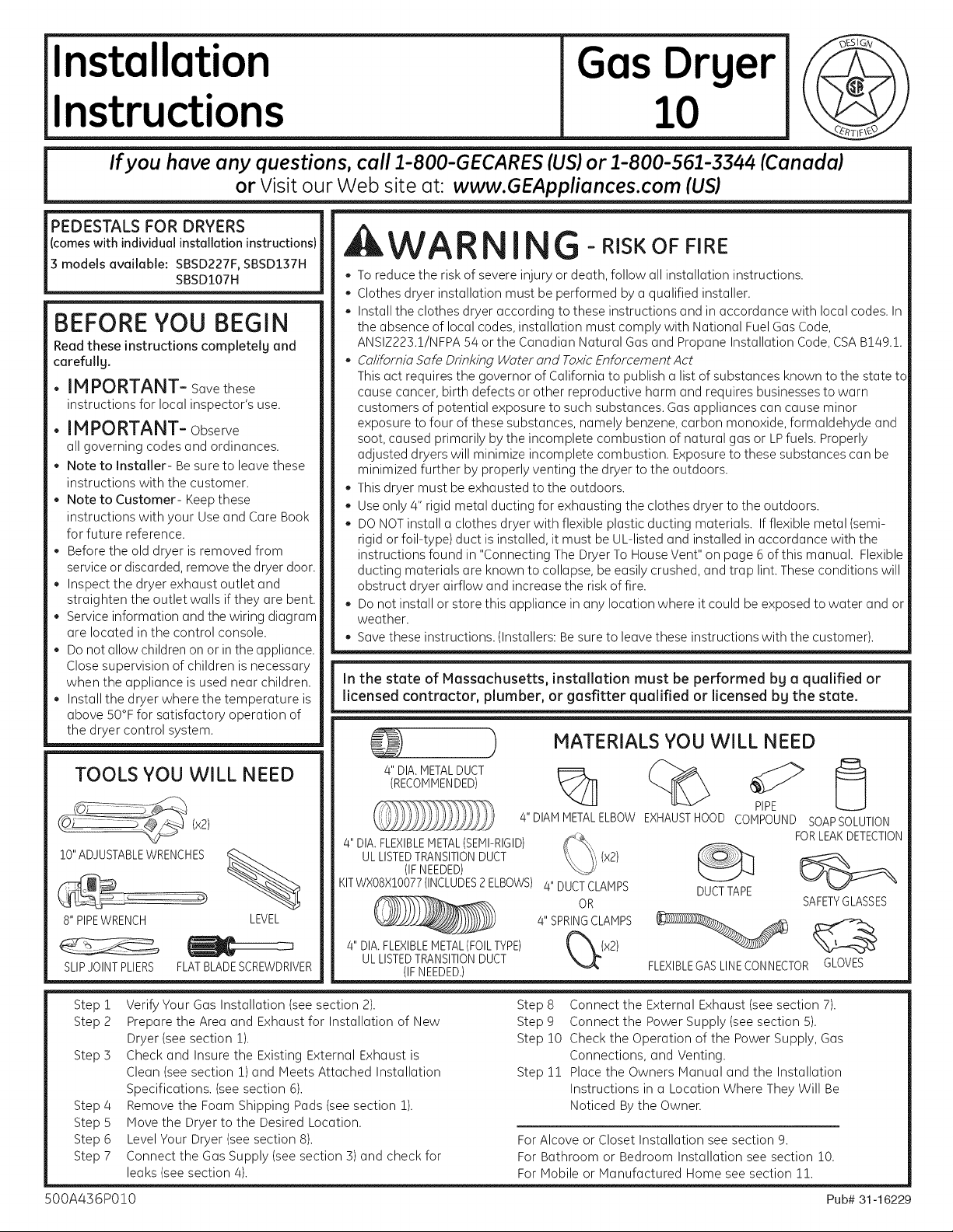
MATERIALS YOU WILL NEED
TOOLS YOU WILL NEED
(x2)
10" ADJUSTABLEWRENCHES
8" PIPEWRENCH
SLIPJOINTPLIERS
Step 1
Step 2
Step 3
Step 4
Step 5
Step 6
Step 7
500A436P010 Pub# 31-16229
Verify Your Gas Installation (see section 2).
Prepare the Area and Exhaust for Installation of New
Dryer (see section 1).
Check and Insure the Existing External Exhaust is
Clean (see section 1) and Meets Attached Installation
Specifications. (see section 6).
Remove the Foam Shipping Pads (see section 1).
Move the Dryer to the Desired Location.
Level Your Dryer (see section 8).
Connect the Gas Supply (see section 3) and check for
leaks (see section 4).
FLATBLADESCREWDRIVER
LEVEL
/4"DIA.METALDUCT
(RECOMMENDED)
4" DIAM METALELBOW EXHAUSTHOOD COMPOUND SOAPSOLUTION
4" DIA.FLEXIBLEMETAL(SEMI-RIGID)
ULLISTEDTRANSITIONDUCT
(IFNEEDED)
KITWXO8X10077(INCLUDES2ELBOWS)
4" DIA,FLEXIBLEMETAL(FOILTYPE)
ULLISTEDTRANSITIONDUCT
(IFNEEDED,)
Step 8 Connect the External Exhaust (see section 7).
Step 9 Connect the Power Supply (see section 5).
Step 10 Check the Operation of the Power Supply, Gas
Step 11 Place the Owners Manual and the Installation
For Alcove or Closet Installation see section 9.
For Bathroom or Bedroom Installation see section 10.
For Mobile or Manufactured Home see section 11.
PIPE
FORLEAKDETECTION
(x2)
4" DUCTCLAMPS _"._J" _
0R SAFETYGLASSES
4" SPRINGCLAMPS
FLEXIBLEGASLINECONNECTORGLOVES
Connections, and Venting.
Instructions in a Location Where They Will Be
Noticed By the Owner.
DUCTTAPE
Page 2
Installation Instructions
Minimum Clearance Other Than Alcove or Closet Installation
Minimum clearance to combustible surfaces and for air opening are: 0 in. clearance both sides and 1 in. rear. Consideration
must be given to provide adequate clearance for proper operation and service.
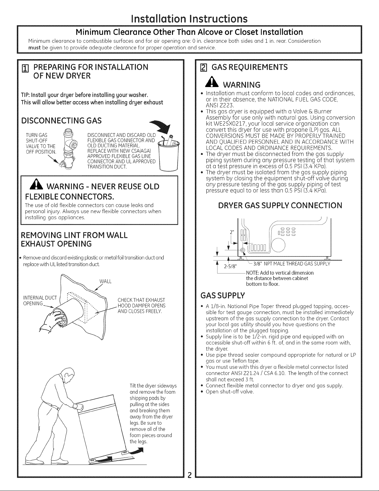
ITI PREPARING FOR INSTALLATION
OF NEW DRYER
TIP:Install your dryer before installing your washer.
This will allow better accesswheninstalling dryer exhaust
DISCONNECTING_ GAS _i v
TURNGAS _ DISCONNECTANDDISCARDOLD
SHUT-OFF I_>_ FLEXIBLEGASCONNECTORAND _CT' _,
OFF
APPROVEDFLEXIBLEGASLINE
CONNECTORAND ULAPPROVED
TRANSITIONDUCT.
WARNING - NEVER REUSE OLD
FLEXIBLE CONNECTORS.
The use of old flexible connectors can cause leaks and
personal injury. Always use new flexible connectors when
installing gas appliances.
REMOVING LINT FROM WALL
EXHAUST OPENING
_] GAS REQUIREMENTS
_i, WARNING
• Installation must conform to local codes and ordinances,
or in their absence, the NATIONAL FUEL GAS CODE,
ANSI Z223.
This gas dryer is equipped with a Valve & Burner
Assembly for use only with natural gas. Using conversion
kit WE25X0217, your local service organization can
convert this dryer for use with propane (LP) gas. ALL
CONVERSIONS HUST BE HADE BY PROPERLYTRAINED
AND QUALIFIED PERSONNEL AND IN ACCORDANCE WITH
LOCAL CODES AND ORDINANCE REQUIREHENTS.
The dryer must be disconnected from the gas supply
piping system during any pressure testing of that system
at a test pressure in excess of 0.5 PSI (3.4 KPa).
The dryer must be isolated from the gas supply piping
system by closing the equipment shut-off valve during
any pressure testing of the gas supply piping of test
pressure equal to or less than 0.5 PSI (].4 KPa).
DRYER GAS SUPPLY CONNECTION
• Removeand discardexistingplasticor metalfoil transitionduct and
replacewith ULlistedtransitionduct.
WALL
INTERNALDUCT
CHECKTHAT EXHAUST
DAMPEROPENS
AND CLOSESFREELY,
Tiltthe dryer sideways
andremovethe foam
shippingpads by
pullingatthe sides
andbreakingthem
awayfrom the dryer
legs.Besureto
removeall of the
foam piecesaround
the legs.
2-5/8"
t
'- 3/8" NPT MALETHREADGASSUPPLY
NOTE: Add to vertical dimension
the distance between cabinet
bottom to floor.
GAS SUPPLY
A 1/8-in. National Pipe Taper thread plugged tapping, acces-
sible for test gauge connection, must be installed immediately
upstream of the gas supply connection to the dryen Contact
your local gas utility should you have questions on the
installation of the plugged tapping.
Supply line isto be 1/2-in. rigid pipe and equipped with an
accessible shut-off within 6 ft. of, and in the same room with,
the dryen
Use pipe thread sealer compound appropriate for natural or LP
gas or use Teflon tape.
You must use with this dryer a flexible metal connector listed
connector ANSI Z21.24 / CSA6.10. The length of the connect
shall not exceed ] ft.
Connect flexible metal connector to dryer and gas supply.
Open shut-off valve.
Page 3
Installation
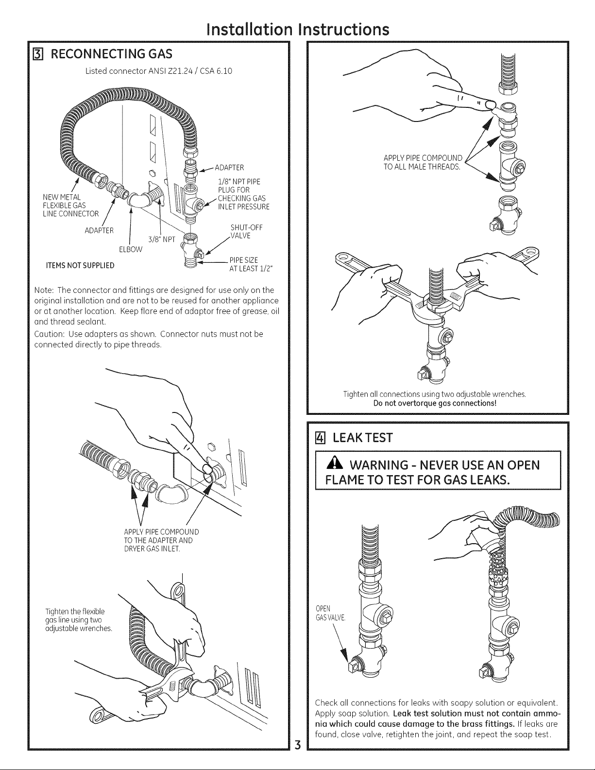
RECONNECTING GAS
B1
Listed connector ANSI Z21.24 / CSA 6.10
1/8" NPTPIPE
NEW METAL
FLEXIBLEGAS INLETPRESSURE
LINECONNECTOR
ADAPTER
3/8" NPT
ELBOW
ITEMSNOT SUPPLIED __ PIPESIZE
Note: The connector and fittings are designed for use only on the
original installation and are notto be reused for another appliance
or at another location. Keep flare end of adaptor free of grease, oil
and thread sealant.
Caution: Useadapters as shown. Connector nuts must not be
connected directly to pipe threads.
PLUGFOR
SHUT-OFF
ATLEAST1/2"
instructions
APPLYPIPECOMPOUND
TOALL MALETHREADS.
Tighten the flexible
gas line using two
adjustable wrenches.
APPLYPIPECOMPOUND
TOTHEADAPTERAND
DRYERGASINLET.
Tighten all connections using two adjustable wrenches.
Do not overtorque gas connections!
[] LEAK TEST
WARNING - NEVER USE AN OPEN
FLAME TO TEST FOR GAS LEAKS.
GASVALVE.
OPEN
Check all connections for leaks with soapy solution or equivalent.
Apply soap solution. Leak test solution must not contain ammo-
nia which could cause damage to the brass fittings. If leaks are
found, close valve, retighten the joint, and repeat the soap test.
Page 4
Installation
Instructions
rs-] ELECTRICAL CONNECTION
INFORMATION
A
_l& WARNING-TO REDUCE THE RISK OF FIRE,
ELECTRICAL SHOCK, AND PERSONAL INJURY:
,, DO NOT USE AN EXTENSION CORD OR AN
ADAPTER PLUG WITH THIS APPLIANCE.
Dryer must be electrically grounded in accordance
with local codes and ordinances, or in the absence of
local codes, in accordance with the NATIONAL ELEC-
TRICAL CODE, ANSI/NFPA NO. 70.
ELECTRICAL REQUIREMENTS
This appliance must be supplied with 120V, 60Hz, and connected
to a properly grounded branch circuit, protected by a 15- or
20-amp circuit breaker or time-delay fuse. If electrical supply
provided does not meet the above specifications, it is recom-
mended that a licensed electrician install an approved outlet.
A
ml, WARNING-THIS DRYER IS EQUIPPED A
THREE-PRONG (GROUNDING) PLUG FOR YOUR
PROTECTION AGAINST SHOCK HAZARD AND
SHOULD BE PLUGGED DIRECTLY INTO A PROP-
ERLY GROUNDED THREE-PRONG RECEPTACLE.
DO NOT CUT OR REMOVE THE GROUNDING
PRONG FROM THIS PLUG.
[63 EXHAUST INFORMATION
_I_WARNING - IN CANADA AND IN THE UNITED STATES,
THE REQUIRED EXHAUST DUCT DIAMETER IS4 IN (102mm).
DO NOT USE DUCT LONGER THAN SPECIFIED IN THE
EXHAUST LENGTH TABLE.
Using exhaust longer than specified length will:
• Increase the drying times and the energy cost.
• Reduce the dryer life.
. Accumulate lint, creating a potential fire hazard.
The correct exhaust installation is YOUR RESPONSIBILITY.
Problems due to incorrect installation are not covered
by the warranty.
Remove and discard existing plastic or metal foil transition duct
and replace with UL listed transition duct.
The HAXIHUH ALLOWABLE duct length and number of bends
of the exhaust system depends upon the type of duct, number
of turns, the type of exhaust hood (wall cap), and all conditions
noted below. The maximum exhaust length for rigid metal duct
is shown in the table below.
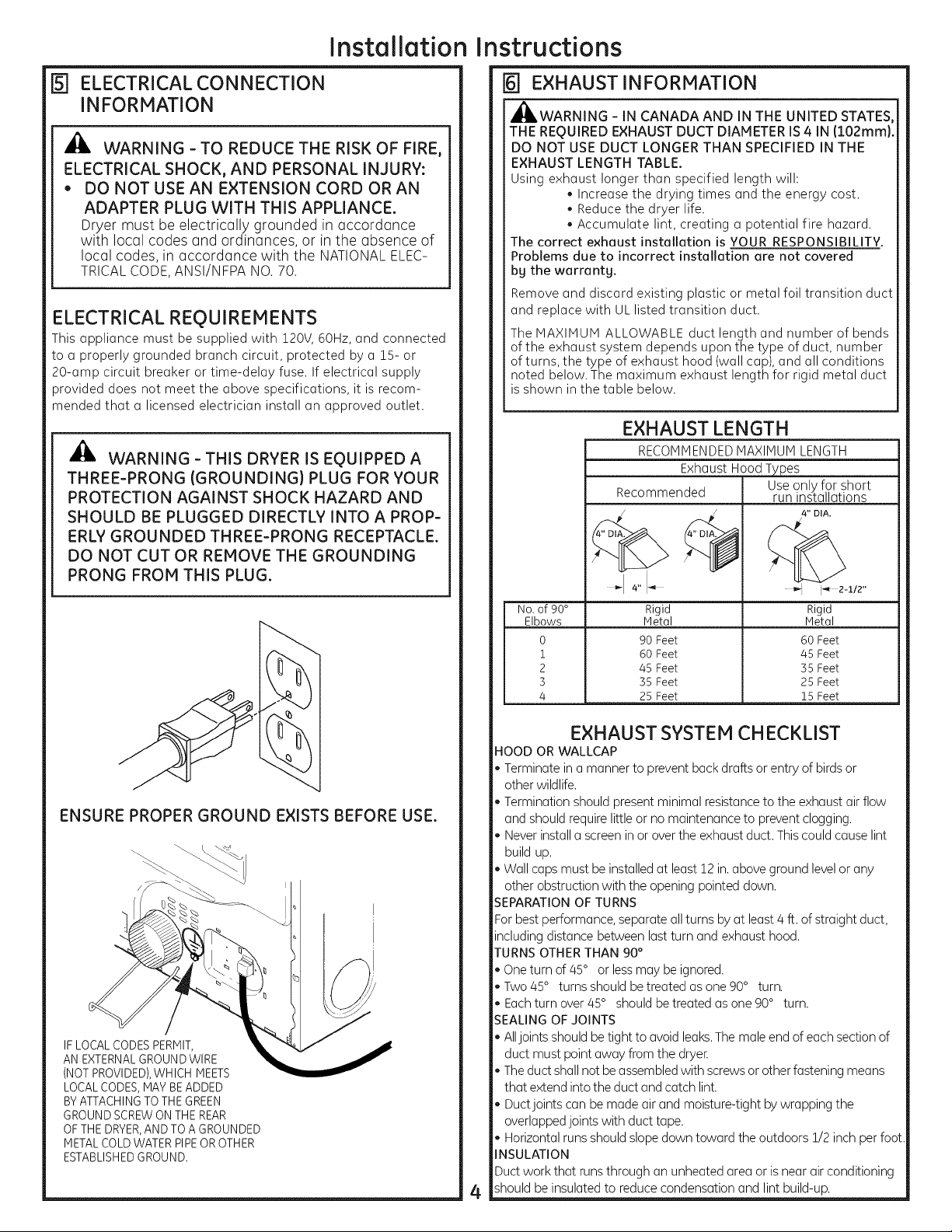
EXHAUST LENGTH
RECOHHENDEDHAXIHUH LENGTH
Exhaust Hood Types
Recommended run installations
4" "q _ _'_ 2-I/2"
No.of 90° Rigid Rigid
Elbows Hetal Hetal
0 90Feet 60Feet
i 60Feet 45 Feet
2 45Feet 35Feet
3 35Feet 25Feet
4 25Feet 15Feet
Use only for short
4" DIA.
ENSURE PROPER GROUND EXISTS BEFORE USE.
IFLOCALCODESPERMIT,
AN EXTERNALGROUNDWIRE
(NOTPROVIDED),WHICH MEETS
LOCALCODES,MAY BEADDED
BYATTACHINGTO THE GREEN
GROUNDSCREWONTHE REAR
OFTHE DRYER,AND TO A GROUNDED
METALCOLD WATERPIPEOR OTHER
ESTABLISHEDGROUND.
EXHAUST SYSTEM CHECKLIST
HOOD OR WALLCAP
• Terminate in a manner to prevent backdrafts or entry of birds or
other wildlife.
• Termination should present minimal resistanceto the exhaust airflow
and should requirelittle or no maintenance to prevent clogging.
• Never install a screenin or over the exhaust duct. Thiscould cause lint
build up.
• Wall capsmust be installed at least12 in.above ground levelor any
other obstruction with the opening pointed down.
SEPARATIONOF TURNS
Forbest performance, separate allturns by at least4 ft. of straight duct,
includingdistance between last turn and exhaust hood.
TURNS OTHERTHAN 90°
• Oneturn of 45° or lessmay be ignored.
• Two 45° turns should betreated asone 90° turn.
• Eachturn over 45° shouldbe treated as one 90° turn.
SEALING OF JOINTS
• Alljoints should betight to avoid leaks.The male end of each sectionof
duct must point away from the dryer
• The duct shall not beassembledwith screwsor other fastening means
that extend into the duct and catch lint.
• Duct joints can be made air and moisture-tight by wrapping the
overlappedjoints with duct tape.
• Horizontal runsshould slope down toward the outdoors 1/2 inch perfoot.
INSULATION
Ductwork that runs through an unheated area or isnear airconditioning
shouldbe insulated to reduce condensation and lint build-up.
4
Page 5
Installation
instructions
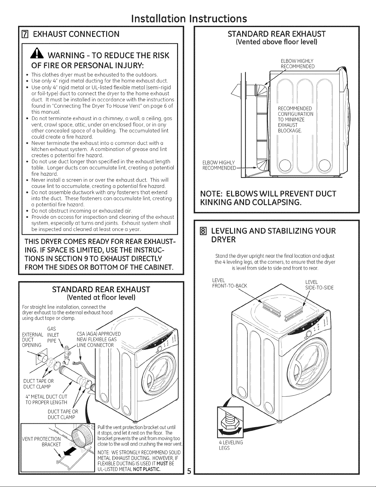
EXHAUST CONNECTION
[]
_1_ WARNING - TO REDUCE THE RISK
OF FIRE OR PERSONAL INJURY:
* This clothes dryer must be exhausted to the outdoors.
. Use only 4" rigid metal ducting for the home exhaust duct.
Use only 4" rigid metal or UL-listed flexible metal (semi-rigid
or foil-type) duct to connect the dryer to the home exhaust
duct. It must be installed in accordance with the instructions
found in "Connecting The Dryer To House Vent" on page 6 of
this manual.
Do not terminate exhaust in a chimney, a wall, a ceiling, gas
vent, crawl space, attic, under an enclosed floor, or in any
other concealed space of a building. The accumulated lint
could create a fire hazard.
Never terminate the exhaust into a common duct with a
kitchen exhaust system. A combination of grease and lint
creates a potential fire hazard.
Do not use duct longer than specified in the exhaust length
table. Longer ducts can accumulate lint, creating a potential
fire hazard.
Never install a screen in or over the exhaust duct. This will
cause lint to accumulate, creating a potential fire hazard.
Do not assemble ductwork with any fasteners that extend
into the duct. These fasteners can accumulate lint, creating
a potential fire hazard.
Do not obstruct incoming or exhausted air.
Provide an access for inspection and cleaning of the exhaust
system, especially at turns and joints. Exhaust system shall
be inspected and cleaned at least once a year.
THIS DRYERCOMES READY FOR REAR EXHAUST-
ING. IF SPACEIS LIMITED, USETHE INSTRUC-
TIONS IN SECTION 9 TO EXHAUST DIRECTLY
FROM THE SIDESOR BOTTOM OF THE CABINET.
STANDARD REAR EXHAUST
(Vented above floor level}
ELBOW HIGHLY
ELBOWHIGHLY
RECOMMENDED--
NOTE: ELBOWS WILL PREVENT DUCT
KINKING AND COLLAPSING.
[] LEVELING AND STABILIZING YOUR
DRYER
Standthe dryer upright nearthe final locationand adjust
the 4 levelinglegs,atthe corners,to ensurethat the dryer
islevelfrom sideto sideand front to rear.
STANDARD REAR EXHAUST
{Vented at floor level}
For straight line installation, connect the
dryer exhaust to the external exhaust hood
using duct tape or clamp.
EXTERNALINLET
DUCT PIPE
OPENING
DUCT TAPEOR
DUCT CLAMP
4" METAL DUCT CUT
TO PROPERLENGTH
VENTPROTECTION
GAS
DUCTTAPEOR
DUCTCLAMP
BRACKET
CSA(AGA)APPROVED
Pullthe ventprotectionbracketout until
itstops,andletit restonthefloor. The
bracketpreventstheunitfrommovingtoo
closeto thewallandcrushingthe rearvent.
NOTE:WE STRONGLYRECOMMENDSOLID
METALEXHAUSTDUCTING.HOWEVER,IF
FLEXIBLEDUCTINGISUSEDITMUSTBE
UL-LISTEDMETALNOT PLASTIC.
LEVEL LEVEL
FRONT-TO-BACK SIDE-TO-SIDE
4 LEVELING
LEGS
5
Page 6

Installation
Instructions,Exhausting
CONNECTING THE DRYER TO HOUSE VENT
RIGID METAL TRANSITION DUCT
* For best drying performance, a rigid metal transition duct is
recommended.
* Rigid metal transitions ducts reduce the risk of crushing and
kinking.
UL-LISTED FLEXIBLEMETAL(SEMI-RIGID}TRANSITION DUCT
* Ifrigid metal duct cannot be used, then UL-listed flexible metal
(semi-rigid) ducting can be used (Kit WX08X!0077).
Never install flexible metal duct in walls, ceilings, floors or other
enclosed spaces.
Total length of flexible metal duct should not exceed 8 feet
(2.4m).
For many applications, installing elbows at both the dryer and
the wall is highly recommended (seeillustrations below). Elbows
allow the dryer to sit close to the wall without kinking and or
crushing the transition duct, maximizing drying performance.
Avoid resting the duct on sharp objects.
UL-LISTED FLEXIBLEMETAL(FOIL-TYPE)TRANSITION DUCT
* Inspecial installations, it may be necessary to connect the dryer
to the house vent using a flexible metal (foil- type) duct. A
UL-listed flexible metal (foil-type)duct may be used ONLYin
installations where rigid metal or flexible metal (semi-rigid)
ducting cannot be used AND where a 4" diameter can be
maintained throughout the entire length of the transition duct.
InCanada and the United States, only the flexible metal(foil-
type) ducts that comply with the "Outline for Clothes Dryer
Transition Duct Subject 2!58A" shall be used.
Never install flexible metal duct in walls, ceilings, floors or other
enclosed spaces.
Total length of flexible metal duct should not exceed 8 feet
(2.4m).
Avoid resting the duct on sharp objects.
For best drying performance:
!. Slide one end of the duct over the clothes dryer outlet
pipe.
2.Secure the duct with a clamp.
3.With the dryer in its permanent position, extend the
duct to its full length. Allow 2" of duct to overlap the
exhaust pipe. Cut off and remove excess duct. Keep the
duct as straight as possible for maximum airflow.
4.Secure the duct to the exhaust pipe with the other
clamp.
Do
EXCESSIVE
LENGTH
EXHAUST_
19-IALCOVE OR CLOSET INSTALLATION
Ifyour dryer is approved for installation in an alcove or closet,
it will be stated on a label on the dryer back.
The dryer MUSTbe vented to the outdoors. See the EXHAUST
INFORMATIONsection.
Minimum clearance between dryer cabinet and adjacent
walls or other surfaces is:
0 in. either side
3 in. front and rear
Minimum vertical space from floor to overhead cabinets,
ceiling, etc. is 43 in. without pedestal, 55 in. with pedestal.
Closet doors must be Iouvered or otherwise ventilated and must
contain a minimum of 60 sq. in. of open area equally distributed.
Ifthe closet contains both a washer and a dryer, doors must
contain a minimum of 120 sq. in. of open area equally distributed.
The closet should be vented to the outdoors to prevent gas
pocketing in case of a gas leak in the supply line.
No other fuel-burning appliance shall be installed in the same
closet with the dryen
NOTE:WHEN THE EXHAUSTDUCT IS LOCATED AT THE REAROF
THE DRYER,MINIMUM CLEARANCE FROM THE WALL IS 5.5 IN.
[_ BATHROOM OR BEDROOM INSTALLATION
* The dryer MUSTbe vented to the outdoors. See EXHAUST
INFORMATIONsection 6.
* The installation must conform with local codes or, in the absence
of local codes, with the NATIONALFUELGASCODE,ANSI Z223.
ELBOW HIGHLY
RECOMMENDED
_LBOWS HIGHLY
[] MOBILE OR MANUFACTURED HOME
INSTALLATION
* Installation must conform to the MANUFACTUREDHOME
CONSTRUCTION& SAFETYSTANDARD,TITLE24, PART52-80 or,
when such standard is not applicable, with AMERICAN
NATIONALSTANDARDFORMOBILEHOME,NO.50lB.
* The dryer MUSTbe vented to the outdoors with the termina-
tion securely fastened to the mobile home structure. (See
EXHAUSTINFORMATIONsection 6.)
* The vent MUSTNOT be terminated beneath a mobile or
manufactured home.
* The vent duct material MUST BEMETAL.
* KIT!4-D346-33 MUSTbe used to attach the dryer securely to
the structure.
The vent MUSTNOTbe connected to any other duct, vent, or
chimney.
Do not use sheet metal screws or other refastening devices
which extend into the interior of the exhaust vent.
Provide an opening with a free area of at least 25 sq. in. for
introduction of outside air into the dryer room.
6
Page 7

Installation Instructions
DRYER EXHAUST TO LEFT OR
BOTTOM OF CABINET
_b, WARNING - PROTECT YOUR HANDS
AND ARMS FROM SHARP EDGES WHEN
WORKING INSIDE CABINET.
REMOVE
SCREW
AND SAVE.
O_REMOVE
DESIRED
KNOCKOUT
(ONEONLY).
Detach and remove the bottom or left side knockout
as desired. Remove the screw inside the dryer exhaust duct
and save. Pull the duct out of the dryer. Protect sharp edges
around the knockout and exhaust opening with the tape.
FIXING HOLE
ADDING NEW DUCT
FIXING
HOLE
LEFTSIDE
EXHAUST
Reconnect the cut portion (A)of the duct to the blower
housing. Make sure that the fixing hole is aligned with
the tab in the base. Use the screw saved previously to secure
the duct in place through the tab on the appliance base.
ADDING ELBOW AND DUCT FOR EXHAUST
TO SIDE OF CABINET
• Pre-assemble 4" elbow with 4" duct. Wrap duct tape around
joint.
• Insert duct assembly, elbow first, through the side opening
and connect the elbow to the dryer internal duct.
CAUTION: Besure not to pull or damage the
electrical wires inside the drger when
inserting the duct.
B A
I_ 11,25"
Cut the duct as shown and keep portion A.
TAB LOCATION
BEND TAB
UP45 °
Through the rear opening, locate the tab in the middle of
the appliance base. Lift the tab to about 45° using a flat
blade screwdriver.
• Apply duct tape as shown on the joint between the dryer
internal duct and the elbow.
DUCT
,TAPE
CAUTION:
Internal duct joints must be
secured with tape, otherwise
theg mag separate and cause
a safetg hazard.
7
Page 8

Installation
nstructions
ADDING ELBOW FOR EXHAUST
THROUGH BOTTOM OF CABINET
Insert the elbow through the rear opening and connect it to
the drger internal duct
Applg duct tape on the joint between the drger internal duct
and elbow, as shown on page 7.
CAUTION:
Internal duct joints must be secured with tape,
otherwise they mag separate and cause a
safety hazard.
ADDING COVER PLATE TO REAR OF
CABINET
| REVERSING THE DOOR SWING
IMPORTANT NOTES
Read the instructions all the wag through before starting.
Handle parts carefullg to avoid scratching paint
Set screws down bg their related parts to avoid using them in
the wrong places.
Provide a non-scratching work surface for the doors.
Normal completion time to reverse the door swing is30-60
minutes.
IMPORTANT: Once gou begin, do not move the cabinet until
door-swing reversal is completed.
These instructions are for changing the hinges from the right side
to the left side - if gou ever want to switch them back to the right
side, follow these same instructions and reverse all references to
the left and right
TOOLS YOU WILL NEED
CresentWrench
(Adjustable)
C¢
°-'°'"°'i i_
PLATE
(KIT WE1H454)
Connect standard metal elbows and ducts to complete the
exhaust sgstem. Cover back opening with a plate (Kit WEIH454)
available from gour local service provider. Place drger in final
location.
_1_ WARNING - NEVER LEAVE THE BACK
OPENING WITHOUT THE PLATE.
TO REGISTER YOUR DRYER
CALLTOLL-FREE
Phillips-Head
Screwdriver
DOOR PARTS
HingeAssembtg
Hinge
Cover
PuttgKnifeor Thin-
BladeScrewdriver
O
Nut(#8)- 2
PlasticCover
©
Washer- 2
1-888-269-1192
Prompt registration confirms gour right to protection under the
terms of gour warrantg.
www.GEAppliances.com (US)
For Questions on Installation, Call: 1-800-626-2005 (US)or
1-800-561-5544 (Canada).
500A456P010 Pub # 51-16229
8
LargeTapping
Screw(#10)...6
A
Tapping
Screw(#8)...2
Machine
Screw(#8)...6
Page 9

Installation Instructions
BEFORE YOU START
1. Unplug the drger from its electrical outlet.
REMOVE DOOR ASSEMBLY
2. Open the door to approximatelg 90 degrees. Remove the 4
screws starting from the bottom to the top. Make sure the
door is supported while removing the screws.
4_
Lag the door down on a soft protected flat surface so that
the inner part faces upward (door resting on the handle side).
5_
Remove the 6 large tapping screws (#10) located around the
perimeter of the door outlining the gasket and the 2 machine
screws (#8)on the hinge side.
2 #8 Machine
Screws
6#10 Large
Screws
2#8 Machine
Screws
Removethe
four screws.
3. Loosen the top screw as shown. Unhook the door bg lifting
and pulling as shown bg the arrows.
6_
With the screws removed, turn the door over and separate
the silver cover part of the door from the door frame and set
aside.
7. Unlock the 4 tabs on the plastic cover and separate the
plastic cover from the frame.
NOTE:Disregard the "DO NOT REMOVE"label on the plastic cover.
//
/ /
/ /
//
/
9
Page 10

Installation Instructions
REMOVE HINGE
IMPORTANT: Note the location of the hinge (left or right) before
removing.
8_
With the door frame part of the door laid down on a
protected soft surface, remove the hinge cover bg removing
the 2 tapping screws (#8) that fasten it to the frame. The
hinge cover is located at the opposite side of the hinge
assemblg_
REINSTALL HINGE ASSEMBLY
11. Place the hinge assemblg in the opposite side of the door.
Align the hinge holes with the door holes.
12. Looselg fasten the hinge assemblg to the edge using
2 machine screws (#8).
cj. Remove the 2 nuts, washers, and the 2 machine screws (#8).
10. Remove the hinge assemblg bg removing the 2 machine
screws (#8) that fasten it to the frame. Pull the hinge
assemblg out and set it aside.
%
l& Hold the door on its side with one hand and fasten the
remaining 2 screws as shown. Then tighten the 2 screws
(#8) holding the hinge assemblg.
1(]
Page 11

Installation Instructions
REINSTALL NUTS AND HINGE COVER
14. Place the door on its edge. Assemble the 2 machine
screws (#8),washers, and nuts. Tighten using a
wrench and screwdriver.
\
1E Placethe hinge cover.in position. Align the hinge cover holes
with the holes in the door.
REASSEMBLE DOOR ASSEMBLY
IMPORTANT: Make sure there is no dirt or ang other foreign
material in between the window panes.
17. Place the plastic cover onto the inner door and lock
in place with the 4 tabs.
18. Place the outer door onto the inner door.
l& Secure the hinge cover with the 2 tapping screws (#8).
/ :
// •/
®
Topof Door
19. After reversing door, there will be a mismatch between the
outer door and the inner door.
Make sure that the handle part of the outer door is opposite
the hinge as shown.
11
Page 12

Installation Instructions
20. Turn the door over and fasten the outer door to the inner
door using the 6 large tapping screws (#!0).
iii,
¢,
MOVE STRIKE BRACKET
21. Using a puttg knife or ang other flat tool, remove the 5
plastic screw caps located on the drger where the door will
be installed and install them on the opposite side.
REINSTALL DOOR ASSEMBLY
23. The door is now readg to be installed on the drger. Toease
this step, the hinge has kegholes that allow a partiallg
fastened screw to be used as a hook.
Partiallg fasten a screw to the uppermost screw hole. Hook
the door on the partiallg fastened screw.
Fasten the hinge bg installing the other 4 screws and
tightening the partiallg fastened screw above.
Partiattg
K
Screws
22. Switch the strike bracket and its cover to the opposite side bg
removing the screws; then reinstall both on the opposite side.
SERVICING
WARNING - LABEL ALL WIRES PRIOR
TO DISCONNECTING WHEN SERVICING
CONTROLS. WIRING ERRORS CAN CAUSE
IMPROPER AND DANGEROUS OPERATION
AFTER SERVICING/INSTALLATION,
For replacement parts and other information, refer to Owner's
Manual for servicing phone numbers.
12
Page 13

ROUGH-IN DIMENSIONS
53 518"
30 518"
40 114"
39 1/8"
13
Page 14

NOTES
 Loading...