

GE DBVH520EJ3WW, DBVH520EJ4WW, DCVH680EJ0MV, DCVH680EJ1BB, DCVH680EJ1MS Installation Guide
...Page 1
Installation
Electric Drger
Instructions
Questions or Installation? Call: 1-800-GECARES (US)
or Visit our Web site at: www.GEApplionces.com (US)
PEDESTALS FOR DRYERS
(comes with individual installation instructions)
Three models available: - SBSD227F
- SBSDIO7H - SBSD137H
BEFOREYOU BEGIN
Read these instructions completelg and carefullg.
•IMPORTANT-savetheseinstructionsforlocal
inspector's use.
• IMPORTANT- Observea,governing codesand
ordinances.
• Note to Installer - Besure to leave these instructions with
the customer.
• Note to Customer- Keepthese instructions with your Use
and Care Book for future reference.
• Before the old dryer is removed from service or discarded,
remove the dryer door.
• Service information and the wiring diagram are located in
the control console.
• Do not allow children on or in the appliance. Closesuper-
vision of children is necessary when the appliance is used
near children.
• Install the dryer where the temperature is above 50°F for
satisfactory operation of the dryer control system.
09
WA ! G- RISKOFFIRE
• To reduce the risk of severe injury or death, follow all installation instructions.
• Clothes dryer installation must beperformed by a qualified installer.
• Install the clothes dryer according to these instructions and in accordance
with local codes.
• This dryer must be exhausted to the outdoors.
• Use only 4" rigid metal ducting for exhausting the clothes dryer to the
outdoors.
• DO NOTinstall a clothes dryer with flexible plastic ducting materials.
If flexible metal (semi-rigid or foil-type) duct is installed, it must be UL listed
and installed in accordance with the instructions found in "Connecting The
Dryer To House Vent" on page S of this manual. Flexible venting materials
are known to collapse, be easily crushed, and trap lint. Theseconditions will
obstruct dryer airflow and increase the risk of fire.
• Do not install or store this appliance in any location where it could be
exposed to water and or weather.
• Save these instructions. (Installers: Be sure to leave these instructions with
the customer).
NOTE: Installation and service of this drger
requires basic mechanical and electrical skills.
It is your responsibilitg to contact a qualified
installer to make the electrical connections.
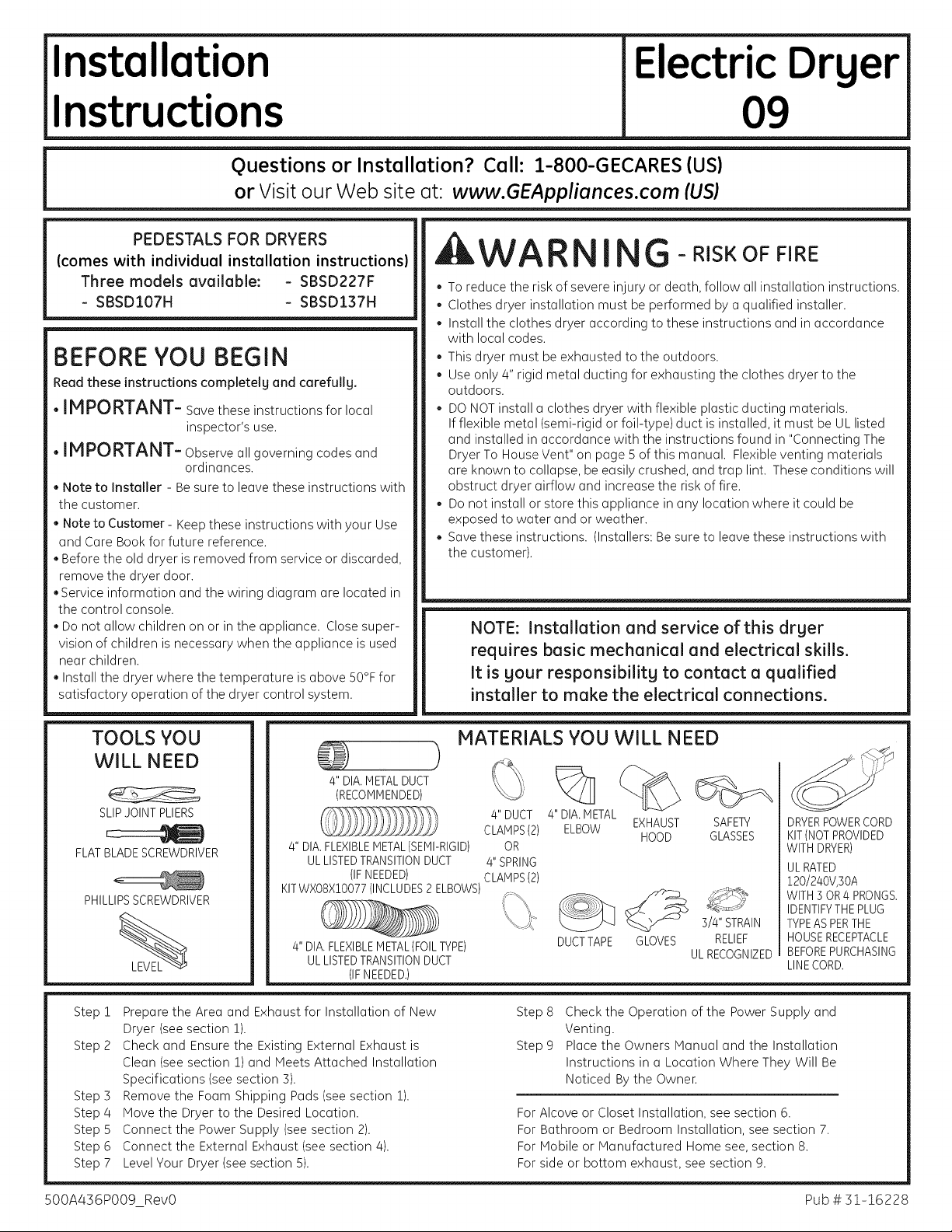
TOOLS YOU
WILL NEED
SLIPJOINT PLIERS
FLAT BLADESCREWDRIVER
PHILLIPSSCREWDRIVER
Step 1
Step 2
Step 3
Step 4
Step 5
Step 6
Step 7
Prepare the Area and Exhaust for Installation of New
Dryer (see section 1).
Check and Ensure the Existing External Exhaust is
Clean (seesection 1) and Meets Attached Installation
Specifications (see section 3).
Remove the Foam Shipping Pads (see section 1).
Move the Dryer to the Desired Location.
Connect the Power Supply (see section 2).
Connect the External Exhaust (see section 4).
Level Your Dryer (see section 5).
MATERIALS YOU WILL NEED
)
4" DIAMETALDUCT
(RECOMMENDED)
4" DIAFLEXIBLEMETAL(SEMI-RIGID)
ULLISTEDTRANSITIONDUCT
(IFNEEDED)
KITWXOSX10077(INCLUDES2 ELBOWS)
4"DIAFLEXIBLEMETAL(FOILTYPE)
ULLISTEDTRANSITIONDUCT
(IFNEEDED.)
%
/4"DUCT
CLAMPS(2)
/4"SPRING
CLAMPS(2)
4"DIA,METAL
ELBOW
OR
DUCTTAPE
Step 8
Step 9
For Alcove or Closet Installation, see section 6.
Check the Operation of the Power Supply and
Venting.
Place the Owners Manual and the Installation
Instructions in a Location Where They Will Be
Noticed Bythe Owner.
For Bathroom or Bedroom Installation, see section 7.
For Mobile or Manufactured Home see, section 8.
For side or bottom exhaust, see section 9.
EXHAUST SAFETY
HOOD GLASSES
3/4" STRAIN
GLOVES
RELIEF
ULRECOGNIZED
DRYERPOWERCORD
KIT(NOTPROVIDED
WITH DRYER)
ULRATED
120/240V,30A
WITH 3 OR4 PRONGS.
IDENTIFYTHEPLUG
TYPEASPERTHE
HOUSERECEPTACLE
BEFOREPURCHASING
LINECORD.
500A436PO09 RevO Pub # 31-16228
Page 2
Installation Instructions
Minimum Clearance Other Than Alcove or Closet Installation
Minimum clearance to combustible surfaces and for air opening are: 0 in. clearance both sides and ! in. rear. Consideration
must be given to provide adequate clearance for installation and service.
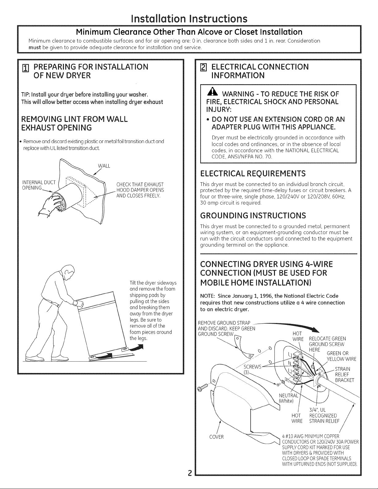
ITI PREPARING FOR INSTALLATION
OF NEW DRYER
TIP:Install gour drger before installing gour washer.
Thiswill allow better accesswhen installing dryer exhaust
REMOVING LINT FROM WALL
EXHAUST OPENING
• Removeand discardexistingplasticor metalfoiltransition ductand
replacewith ULlistedtransitionduct.
WALL
INTERNALDUCT
CHECKTHAT EXHAUST
DAMPEROPENS
AND CLOSESFREELY.
[] ELECTRICAL CONNECTION
INFORMATION
A
WARNING-TO REDUCE THE RISK OF
FIRE, ELECTRICAL SHOCK AND PERSONAL
INJURY:
, DO NOT USE AN EXTENSION CORD OR AN
ADAPTER PLUG WITH THIS APPLIANCE.
Dryer must be electrically grounded in accordance with
local codes and ordinances, or in the absence of local
codes, in accordance with the NATIONALELECTRICAL
CODE,ANSI/NFPA NO. 70.
ELECTRICAL REQUIREMENTS
This dryer must be connected to an individual branch circuit,
protected by the required time-delay fuses or circuit breakers. A
four or three-wire, single phase, !20/240V or !20/208V, 60Hz,
30 amp circuit is required.
GROUNDING INSTRUCTIONS
This dryer must be connected to a grounded metal, permanent
wiring system, or an equipment-grounding conductor must be
run with the circuit conductors and connected to the equipment
grounding terminal on the appliance.
Tiltthe dryersideways
andremovethefoam
shippingpads by
pullingatthe sides
andbreakingthem
awayfrom the dryer
legs.Besureto
removeallof the
foam piecesaround
the legs.
CONNECTING DRYER USING 4-WIRE
CONNECTION (MUST BE USED FOR
MOBILE HOME INSTALLATION)
NOTE: Since ganuarg 1, 1996, the National Electric Code
requires that new constructions utilize a 4 wire connection
to an electric drger.
REMOVEGROUND STRAP .
AND DISCARD.KEEPGREEN
GROUND SCREW
COVER
HOT
WIRE RELOCATEGREEN
/ S/4", UL
HOT RECOGNIZED
WIRE STRAINRELIEF
4 #i0 AWGMINIMUMCOPPER
CONDUCTORSOR120/240V 30A POWER
SUPPLYCORDKITMARKEDFORUSE
WITHDRYERS& PROVIDEDWITH
CLOSEDLOOPORSPADETERMINALS
WITHUPTURNEDENDS(NOTSUPPLIED1,
2
GROUNDSCREW
[RE
GREENOR
YELLOWWIRE
Page 3
Installation
Instructions
1. Turn offthe circuit breaker(s)(30 amp) or remove the dryer's
circuit fuse at the electrical box.
2. Besure the dryer cord is unplugged from the wall receptacle.
3. Remove the power cord cover located at the lower back.
4. Remove and discard ground strap. Keep the green ground screw
for step 7.
5. Install 3/4 in. UL recognized strain relief to power cord entry hole.
Bring power cord through strain reliefi
6. Connect power cord as follows:
A. Connect the 2 hot lines to the outer screws of the terminal
block (marked L1 and L2).
B. Connect the neutral (white) line to the center of the terminal
block (marked N).
7. Attach ground wire of power cord with the green ground screw
(hole above strain relief bracket). Tighten all terminal block
screws (3)completely.
8. Properly secure power cord to strain relief.
9. Reinstall the cover.
[ _ WARNING-NEVERLEAVETHE ]
COVER OFF OF THE TERMINAL BLOCK.
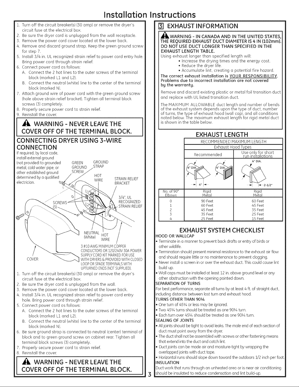
CONNECTING DRYER USING 3-WIRE
CONNECTION
Ifrequired,by localcode,
installexternalground
(notprovided)to grounded
metal,coldwater pipe,or
other establishedground
determinedbya qualified
electrician.
GREEN GROUND
GROUND _TRAP
SCREW
zJ
HOT
WIRE
STRAINRELIEF
BRACKET
3/4", UL
RECOGNIZED
RELIEF
r3-] EXHAUST INFORMATION
_,WARNING - IN CANADA AND IN THE UNITED STATES,
THE REQUIRED EXHAUST DUCT DIAMETER IS4 IN (102rnrn).
DO NOT USE DUCT LONGER THAN SPECIFIED IN THE
EXHAUST LENGTH TABLE.
Using exhaust longer than specified length will:
• Increase the drying times and the energy cost.
Reduce the dryer life.
Accumulate lint, creating a potential fire hazard.
The correct exhaust installation is YOUR RESPONSIBILITY.
Problems due to incorrect installation are not covered
bg the warrantg.
Remove and discard existing plastic or metal foil transition duct
and replace with UL listed transition duct.
The MAXIMUM ALLOWABLE duct length and number of bends
of the exhaust system depends upon the type of duct, number
of turns, the type of exhaust hood (wall cap), and all conditions
noted below. The maximum exhaust length for rigid metal duct
is shown inthe table below.
EXHAUST LENGTH
RECOMMENDEDMAXIMUM LENGTH
Exhaust HoodT _es
Recommended run installations
4" "I _ i_ 2-I12"
No.of 90° Rigid Rigid
Elbows IVletaI IVletal
0 90Feet 60 Feet
i 60Feet 45 Feet
2 45 Feet 35 Feet
3 35Feet 25 Feet
4 25Feet 15Feet
Use only for short
4" DIA.
NEUTRAL
(White) WIRE
3#i0 AWGMINIMUMCOPPER
CONDUCTORSOR120/240V30APOWER
SUPPLYCORDKITMARKEDFORUSE
COVER WITHDRYERS& PROVIDEDWITHCLOSED
LOOPORSPADETERMINALSWITH
UPTURNEDENDS(NOTSUPPLIED).
1. Turn off the circuit breaker(s)(30 amp) or remove the dryer's
circuit fuse at the electrical box.
2. Besure the dryer cord is unplugged from the wall.
3. Remove the power cord cover located at the lower back.
4. Install 3/4 in. UL recognized strain relief to power cord entry
hole. Bring power cord through strain relief.
5. Connect power cord as follows:
A. Connect the 2 hot lines to the outer screws of the terminal
block (marked L1 and L2).
B. Connect the neutral (white) line to the center of the terminal
block (marked N).
6. Besure ground strap is connected to neutral (center) terminal of
block and to green ground screw on cabinet rean Tighten all
terminal block screws (3)completely.
7. Properly secure power cord to strain relief.
8. Reinstall the cover.
HOT
COVER OFF OF THE TERMINAL BLOCK.
EXHAUST SYSTEM CHECKLIST
HOOD OR WALLCAP
Terminate ina manner to prevent backdrafts or entry of birdsor
other wildlife.
Termination should presentminimal resistanceto the exhaust air flow
and should requirelittle or no maintenance to prevent clogging.
Neverinstallascreen in or overthe exhaust duct. Thiscould causelint
build up.
Wall caps must be installed at least12 in.above ground levelor any
other obstruction with the opening pointed down.
EPARATIONOFTURNS
Forbest performance,separate allturns by at least4ft. of straight duct,
including distance between last turn and exhaust hood.
TURNSOTHERTHAN 901A
Oneturn of451Aor lessmay be ignored.
Two 451Aturns should betreated asone 90_Aturn.
Eachturn over45_Ashould be treatedasone 90_Aturn.
EALING OF JOINTS
Alljoints should betight to avoid leaks.The male end of each section of
duct must point away from the dryer
Theduct shallnot beassembledwith screwsor other fastening means
that extend into the duct and catch lint.
Ductjoints can bemade air and moisture-tight by wrapping the
overlappedjoints with duct tape.
Horizontal runs shouldslope down toward the outdoors 1/2 inch per foot.
_ISULATION
Ductwork that runsthrough an unheated area or isnear air conditioning
should be insulated to reduce condensation and lint build-up.
Page 4
Installation
instructions
[] EXHAUST CONNECTION
WARNING - TO REDUCE THE RISK
OF FIRE OR PERSONAL INJURY:
* This clothes dryer must be exhausted to the outdoors.
. Useonly 4" rigid metal ducting for the home exhaust duct.
Use only 4" rigid metal or UL-listed flexible metal (semi-rigid
or foil-type) duct to connect the dryer to the home exhaust
duct. It must be installed in accordance with the instructions
found in "Connecting The Dryer To House Vent" on page 5 of
this manual.
Do not terminate exhaust in a chimney, a wall, a ceiling, gas
vent, crawl space, attic, under an enclosed floor, or in any
other concealed space of a building. The accumulated lint
could create afire hazard.
Never terminate the exhaust into a common duct with a
kitchen exhaust system. Acombination of grease and lint
creates a potential fire hazard.
Do not use duct longer than specified in the exhaust length
table. Longer ducts can accumulate lint, creating a potential
fire hazard.
Never install a screen in or over the exhaust duct. Thiswill
cause lint to accumulate, creating a potential fire hazard.
Do not assemble ductwork with any fasteners that extend
into the duct. These fasteners can accumulate lint, creating
a potential fire hazard.
Do not obstruct incoming or exhausted air.
Provide an access for inspection and cleaning of the exhaust
system, especially at turns andjoints. Exhaust system shall
be inspected and cleaned at least once ayear.
THIS DRYER COMES READY FOR REAR
EXHAUSTING. IF SPACE IS LIMITED, USE
THE INSTRUCTIONS IN SECTION 9 TO
EXHAUST DIRECTLY FROM THE SIDES OR
BOTTOM OF THE CABINET.
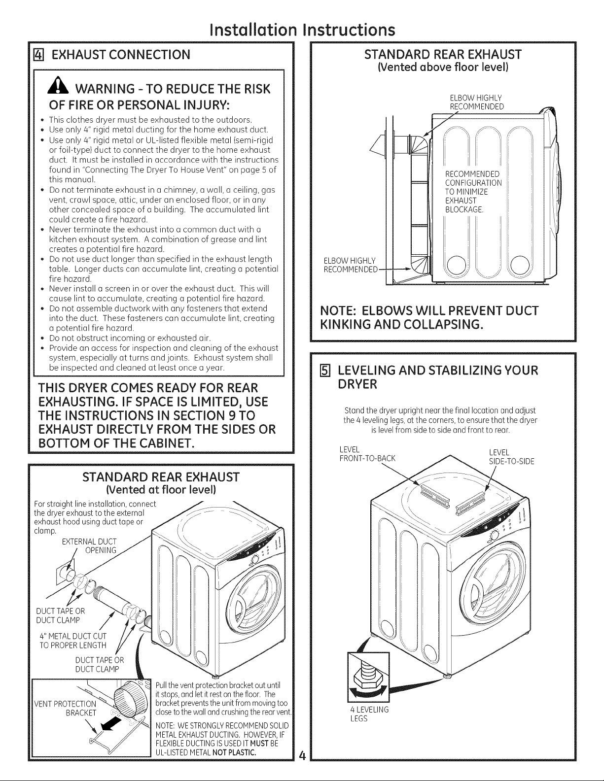
STANDARD REAR EXHAUST
(Vented at floor level}
For straight line installation, connect
the dryer exhaust to the external
exhaust hood using duct tape or
clamp.
EXTERNALDUCT
OPENING
STANDARD REAR EXHAUST
(Vented above floor level}
ELBOWHIGHLY
_ECOMMENDED ,,_
ELBOW HIGHLY
RECOMMENDED- -
NOTE: ELBOWS WILL PREVENT DUCT
KINKING AND COLLAPSING.
r5-] LEVELING AND STABILIZING YOUR
DRYER
Standthe dryer upright nearthe final locationand adjust
the 4 levelinglegs,at the corners,to ensurethat the dryer
islevelfrom sideto side andfront to rear.
LEVEL LEVEL
FRONT-TO-BACK SIDE-TO-SIDE
DUCTTAPEOR
DUCTCLAMP
4" METALDUCT CUT
TOPROPERLENGTH
DUCT TAPEOR
DUCT CLAMP
VENTPROTECTION
BRACKET
Pulltheventprotectionbracketoutuntil
it stops,and letitrestonthefloor.The
bracketpreventsthe unitfrommovingtoo
closeto the wallandcrushingtherearvent.
NOTE:WESTRONGLYRECOMMENDSOLID
METALEXHAUSTDUCTING. HOWEVER,IF
FLEXIBLEDUCTINGISUSEDITMUSTBE
UL-LISTEDMETALNOTPLASTIC.
4 LEVELING
LEGS
4
Page 5

Installation Instructions, Exhausting
CONNECTING THE DRYER TO HOUSE VENT
RIGID METAL TRANSITION DUCT
For best drying performance, a rigid metal transition duct is
recommended.
Rigid metal transitions ducts reduce the risk of crushing and
kinking.
UL-LISTEDFLEXIBLEMETAL(SEMI-RIGID}TRANSITION DUCT
• If rigid metal duct cannot be used, then UL-listed flexible metal
(semi-rigid) ducting can be used (Kit WXO8X!O077).
Never install flexible metal duct in walls, ceilings, floors or other
enclosed spaces.
Total length of flexible metal duct should not exceed 8feet
(2.4m).
For many applications, installing elbows at both the dryer and
the wall is highly recommended (see illustrations below). Elbows
allow the dryer to sit close to the wall without kinking and or
crushing the transition duct, maximizing drying performance.
Avoid resting the duct on sharp objects.
UL-LISTEDFLEXIBLEMETAL(FOIL-TYPE}TRANSITION DUCT
* In special installations, it may be necessary to connect the dryer
to the house vent using a flexible metal (foil- type) duct. A
UL-listed flexible metal (foil-type)duct may be used ONLYin
installations where rigid metal or flexible metal (semi-rigid)
ducting cannot be used AND where a 4" diameter can be
maintained throughout the entire length of the transition duct.
In Canada and the United States, only the flexible metal(foil-
type) ducts that comply with the "Outline for Clothes Dryer
Transition Duct Subject 2!S8A" shall be used.
Never install flexible metal duct in walls, ceilings, floors or other
enclosed spaces.
Total length of flexible metal duct should not exceed 8feet
(2.4m).
Avoid resting the duct on sharp objects.
For best drying performance:
!. Slide one end of the duct over the clothes dryer outlet
pipe.
2. Secure the duct with a clamp.
3. With the dryer in its permanent position, extend the
duct to its full length. Allow 2" of duct to overlap the
exhaust pipe. Cut off and remove excess duct. Keep the
duct as straight as possible for maximum airflow.
4. Secure the duct to the exhaust pipe with the other
clamp.
[6-IALCOVE OR CLOSET INSTALLATION
Ifyour dryer is approved for installation in an alcove or closet,
it will be stated on a label on the dryer back.
The dryer MUSTbe vented to the outdoors. See the EXHAUST
INFORMATIONsections 3 & 4.
Minimum clearance between dryer cabinet and adjacent
walls or other surfaces is:
0 in. either side
3 in. front and rear
Minimum vertical space from floor to overhead cabinets,
ceiling, etc. is 43 in.without pedestal, SSin. with pedestal.
Closet doors must be Iouvered or otherwise ventilated and
must contain a minimum of 60 sq. in. of open area equally
distributed. If the closet contains both a washer and a dryer,
doors must contain a minimum of 120 sq. in. of open area
equally distributed.
NOTE: WHEN THE EXHAUST DUCT IS LOCATED AT THE
REAR OF THE DRYER, MINIMUM CLEARANCE FROM THE
WALL IS 5.5 IN.
171BATHROOM OR BEDROOM
INSTALLATION
The dryer MUSTbe vented to the outdoors. See EXHAUST
INFORMATIONsection 3 & 4.
The installation must conform with local codes or, in the
absence of local codes, with the NATIONALELECTRICALCODE,
ANSI/NFPA NO. 70.
ELBOW HIGHLY
RECOMMENDED
I _OWSHIGHLY
J
[] MOBILE OR MANUFACTURED HOME
INSTALLATION
* Installation must conform to the MANUFACTUREDHOME
CONSTRUCTION& SAFETYSTANDARD,TITLE 24, PART32-80 or,
when such standard is not applicable, with AMERICAN
NATIONALSTANDARDFORMOBILEHOME,ANSI/NFPA NO.
501B.
, The dryer HUST be vented to the outdoors with the termina-
tion securely fastened to the mobile home structure. (See
EXHAUSTINFORHATIONsection 3 & 4.)
, The vent HUST NOTbe terminated beneath a mobile or
manufactured home.
, The vent duct material HUST BE HETAL
, Do not use sheet metal screws or other fastening devices
which extend into the interior of the exhaust vent.
, Seesection 2 for electrical connection information.
5
Page 6

Installation Instructions
19-1DRYER EXHAUST TO RIGHT, LEFT OR
BOTTOM CABINET
WARNING - BEFORE PERFORMING
THIS EXHAUST INSTALLATION, BE SURE
TO DISCONNECT THE DRYER FROM ITS
ELECTRICAL SUPPLY. PROTECT YOUR
HANDS AND ARMS FROM SHARP EDGES
WHEN WORKING INSIDE THE CABINET.
BESURE TO WEAR GLOVES.
REMOVE
SCREW
AND SAVE.
REMOVE
DESIRED
KNOCKOUT
(ONE ONLY).
Detach and remove the bottom, right or left side knockout as
desired. Remove the screw inside the drger exhaust duct and
save. Pull the duct out of the drger.
ADDING NEW DUCT
FIXING
HOLE
\
PORTION"A"
\
RIGHTOR
LEFTSIDE
EXHAUST
Reconnect the cut portion (A)of the duct to the blower housing.
Make sure that the shortened duct is aligned with the tab in the
base. Use the screw saved previouslg to secure the duct in place
through the tab on the appliance base.
ADDING ELBOW AND DUCT FOR EXHAUST
TO LEFT OR RIGHT SIDE OF CABINET
• Preassemble 4" elbow with 4" duct. Wrap duct tape around
joint.
Insert duct assemblg, elbow first, through the side opening
and connect the elbow to the drger internal duct.
CAUTION: Be sure not to pull or damage the
electrical wires inside the dryer when
inserting the duct.
FIXING HOLE
B A
14 11.25"
Cut the duct as shown and keep portion A.
TAB LOCATION
Through the rear opening, locate the tab in the middle of the
appliance base. Lift the tab to about 451A using a flat blade
screwdriver.
o
DUCT
j TAPE
• Applg duct tape as shown on the joint between the drger
internal duct and the elbow.
DUCT
CAUTION:
Internal duct joints must be
secured with tape, otherwise
theg mag separate and cause
a safety hazard.
6
Page 7

Installation
nstructions
ADDING ELBOW FOR EXHAUST
THROUGH BOTTOM OF CABINET
Insert the elbow through the rear opening and connect it to
the drger internal duct
Applg duct tape on the joint between the drger internal duct
and elbow, as shown on page 7.
CAUTION:
Internal duct joints must be secured with tape,
otherwise they mag separate and cause a
safety hazard.
ADDING COVER PLATE TO REAR OF
CABINET
REVERSING THE DOOR SWING
IMPORTANT NOTES
Read the instructions all the wag through before starting.
Handle parts carefullg to avoid scratching paint
Set screws down bg their related parts to avoid using them in
the wrong places.
Provide a non-scratching work surface for the doors.
Normal completion time to reverse the door swing is50-60
minutes.
IMPORTANT: Once gou begin, do not move the cabinet until
door-swing reversal iscompleted.
These instructions are for changing the hinges from the right side
to the left side - if gou ever want to switch them back to the right
side, follow these same instructions and reverse all references to
the left and right
TOOLS YOU WILL NEED
CresentWrench
(Adjustable)
C¢
°-'°'"°'i i_
PLATE
(KIT WE1N454)
Connect standard metal elbows and ducts to complete the
exhaust sgstem. Cover back opening with a plate (Kit WEIM454)
available from gour local service provider. Place drger in final
location.
_1_ WARNING - NEVER LEAVE THE BACK
OPENING WITHOUT THE PLATE.
TO REGISTER YOUR DRYER
CALLTOLL-FREE
Phillips-Head
Screwdriver
DOOR PARTS
HingeAssembtg
Hinge
Cover
PuttgKnifeor Thin-
BladeScrewdriver
O
Nut(#8)- 2
PlasticCover
©
Washer- 2
1-888-269-1192
Prompt registration confirms gour right to protection under the
terms of gour warrantg.
www.GEAppliances.com (US)
For Questions on Installation, Call: 1-800-626-2005 (US)or
1-800-561-5400(Canada).
500A456P009 Pub # 32-26228
7
LargeTapping
Screw(#10)...6
A
Tapping
Screw(#8)...2
Machine
Screw(#8)...6
Page 8

Installation Instructions
BEFORE YOU START
1. Unplug the drger from its electrical outlet.
REMOVE DOOR ASSEMBLY
2. Open the door to approximatelg 90 degrees. Remove the 4
screws starting from the bottom to the top. Make sure the
door is supported while removing the screws.
4_
Lag the door down on a soft protected flat surface so that
the inner part faces upward (door resting on the handle side).
5_
Remove the 6 large tapping screws (#10) located around the
perimeter of the door outlining the gasket and the 2 machine
screws (#8) on the hinge side.
2 #8 Machine
Screws
6#10 Large
Screws
2#8 Machine
Screws
Removethe
four screws.
3. Loosen the top screw as shown. Unhook the door bg lifting
and pulling as shown bg the arrows.
6_
With the screws removed, turn the door over and separate
the silver cover part of the door from the door frame and set
aside.
7. Unlock the 4 tabs on the plastic cover and separate the
plastic cover from the frame.
NOTE:Disregard the "DO NOT REMOVE"label on the plastic cover.
//
/ /
/ /
//
/
8
Page 9

Installation Instructions
REMOVE HINGE
IMPORTANT: Note the location of the hinge (left or right) before
removing.
8_
With the door frame part of the door laid down on a
protected soft surface, remove the hinge cover bg removing
the 2 tapping screws (#8) that fasten it to the frame. The
hinge cover is located at the opposite side of the hinge
assemblg_
REINSTALL HINGE ASSEMBLY
11. Place the hinge assemblg in the opposite side of the door.
Align the hinge holes with the door holes.
12. Looselg fasten the hinge assemblg to the edge using
2 machine screws (#8).
cj. Remove the 2 nuts, washers, and the 2 machine screws (#8).
10. Remove the hinge assemblg bg removing the 2 machine
screws (#8) that fasten it to the frame. Pull the hinge
assemblg out and set it aside.
%
l& Hold the door on its side with one hand and fasten the
remaining 2 screws as shown. Then tighten the 2 screws
(#8) holding the hinge assemblg.
9
Page 10

Installation Instructions
REINSTALL NUTS AND HINGE COVER
14. Place the door on its edge. Assemble the 2 machine
screws (#8), washers, and nuts. Tighten using a
wrench and screwdriver.
\
1E Place the hinge cover.in position. Align the hinge cover holes
with the holes in the door.
REASSEMBLE DOOR ASSEMBLY
IMPORTANT: Make sure there is no dirt or ang other foreign
material in between the window panes.
17. Place the plastic cover onto the inner door and lock
in place with the 4 tabs.
18. Place the outer door onto the inner door.
l& Secure the hinge cover with the 2 tapping screws (#8).
/ :
// • /
®
Topof Door
19. After reversing door, there will be a mismatch between the
outer door and the inner door.
Make sure that the handle part of the outer door is opposite
the hinge as shown.
lC
Page 11

Installation Instructions
20. Turn the door over and fasten the outer door to the inner
door using the 6 large tapping screws (#!0).
iii,
¢,
MOVE STRIKE BRACKET
21. Using a puttg knife or ang other flat tool, remove the 5
plastic screw caps located on the drger where the door will
be installed and install them on the opposite side.
REINSTALL DOOR ASSEMBLY
23. The door is now readg to be installed on the drger. To ease
this step, the hinge has kegholes that allow a partiallg
fastened screw to be used as a hook.
Partiallg fasten a screw to the uppermost screw hole. Hook
the door on the partiallg fastened screw.
Fasten the hinge bg installing the other 4 screws and
tightening the partiallg fastened screw above.
Partiattg
K
Screws
22. Switch the strike bracket and its cover to the opposite side bg
removing the screws; then reinstall both on the opposite side.
SERVICING
WARNING - LABEL ALL WIRES PRIOR
TO DISCONNECTING WHEN SERVICING
CONTROLS. WIRING ERRORS CAN CAUSE
IMPROPER AND DANGEROUS OPERATION
AFTER SERVICING/INSTALLATION,
For replacement parts and other information, refer to Owner's
Manual for servicing phone numbers.
11
Page 12

ROUGH-IN DIMENSIONS
27"
30 518"
39 1/8"
53 518"
13 3/8"
12
 Loading...