

GE Current Lumination IS Series, Current Lumination ISS Series, Current Lumination ISI Series, Current Lumination ISC Series Installation Manual
LuminationTMLED Luminaire
(IS Series)
There are three types of fixtures:
• S
tarter (ISS series)
• Continuous (ISC series)
• Independent (IS1series)
Use Starter Kit in general case. Use Starter SKU if preferred.
BEFORE YOU BEGIN
Read these instructions completely and carefully.
Important notes included below and on page 3.
WARNING/AVERTISSEMENT
RISK OF ELECTRICSHOCK
• Turn power off before inspection, installation or removal.
• Properly ground electricalenclosure.
RISK OF ELECTRICSHOCK
• Follow all NEC and local codes.
• Use only UL approved wire for input/output connections.
Minimumsize 18 AWG or 14AWG for continuous runs.
• When using multi-branch wire circuits with a sharedneutral,do not
operate any circuit with the neutral open. Also ensure all neutral connections
are secure before energizing the circuit.An openneutral can cause an
overvoltage condition at the luminairepower supply.
RISQUES DE DÉCHARGESÉLECTRIQUES
• Coupez l’alimentation avant d’inspecter, installer ou déplacer le luminaire.
• Assurez-vous de correctement mettre à la terre le boîtier
d’alimentationélectrique.
RISQUESD’INCENDIE
• Respectez tous les codes NEC et codes locaux.
• N’utilisez que des fils approuvés par UL pour les entrées/sorties de
connexion. Tailleminimum 18AWG ou14 AWG pour les rangées continues.
• Lorsque vous utilisezdes circuits câblés à branches multiples avec un
neutre commun, nemettez aucuncircuit en service avec le neutre ouvert.
Assurez-vous également que tous les raccords neutres soit sécurisés avant
de mettre le circuit soustension. Un neutre ouvert peut causer une condition
de surtensionà l’alimentation du luminaire.
Installation Guide
Save These Instructions
Use only in the manner intended by the manufacturer. If
you have any questions, contact themanufacturer.
Prepare Electrical Wiring
Electrical Requirements
The LED fixturemust be supplied with 120-277VAC,
50/60Hz or 347V, 50/60Hz and protected by a max.
20 ampere circuit breaker. Use min. 75°C supply
conductor. 347V power should only be supplied to
luminaires with voltage code “D”.
Grounding Instructions
The grounding and bonding of the overall system
shall be done in accordance with National Electric
Code (NEC) Article 600 and local codes.
Components Supplied:
• Luminaire
• 2 MountingBrackets
• End Caps (2supplied with IS1 series and ISS series)
Note: In general case, with the Starter Kit, the Starter SKU
will notbe required.
Tools and Components Required:
• T15 torx or phillips #2screwdriver
• UL Listed conduit connectionsper NEC/CEC
for nominalconduit trade sizes ½” or ¾”
• UL Listed wire connectors
Table of Contents Page
Accessory Kits
Installation of an Independent Unit (IS1) 3
Installation of a Continuous Row using a Starter Kit 4
Installation of a Continuous Row with Optional
BranchCircuit
PSU Replacement 10
Light Engine Replacement 11
2
6
1
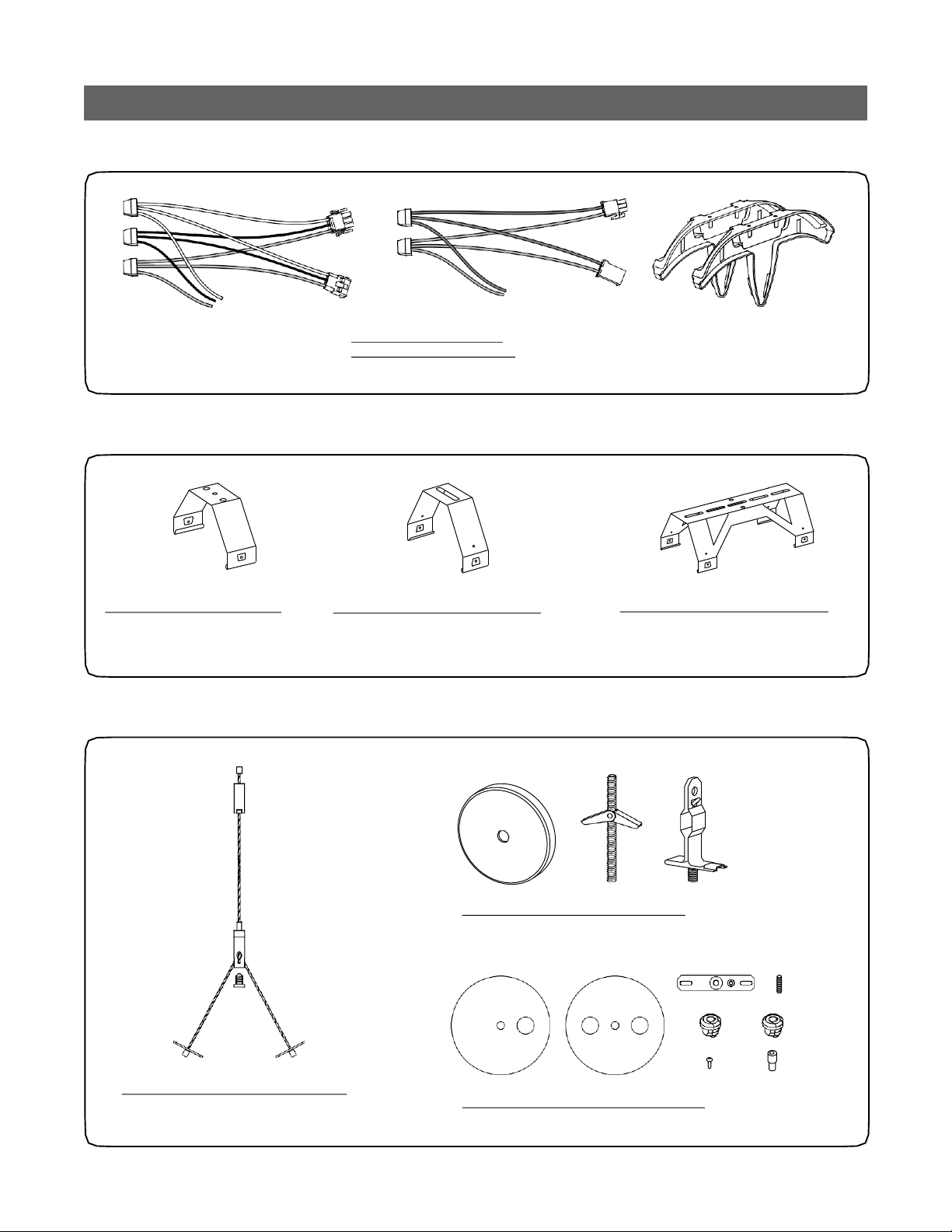
Accessory Kits (purchasedseparately)
Starter Kits
93018007 - Starter Kit (1row)
93022791 - Starter Kit (10rows)
Use to connect a continuous row of fixtures tosupply leads
Mounting Brackets
94210 - Standard Kit (10brackets)
Use if extra brackets are required
SuspensionKits
9308800 - Anti-snaking Kit (10brackets)
Use if installation geometry requires a mounting
point up to 1” off axis of continuous row
93026986 - Upper Mounting Kit (pack of2)
Use to provide mounting anchor infinished ceiling
210221 - Joint Spanning Kit (5 brackets)
Use if installation geometry requires a
mounting point directly over fixture/fixture
junction
93026985 - Lower Mounting Kit (pack of 2)
Use to suspend luminaire up to 10’ below fixed
structure or Upper MountingKit
93026987 - Power Feed CanopyKit (pack of 1)
Use to cover exposed junction boxin pendant mount applications
2
IMPORTANT - Maximum Length of Electrical Run
IS of First Generation IS of Second Generation
Lumen Code LumenCode
Voltage A E,G,S or J B,F or K M,N,P or R U,V,W or X
120V 192’ 160’ 80’ 60’
277V or 347V 400’ 320’ 188’ 132’
• Please see technical data sheet for electrical properties
to ensure safe installation.
• Under any circumstance, maximum driver current
through connectedfixtures shall not exceed15A for
types A, G, J,B, F, K, or E.
• Maximum drive current through connectedfixtures shall
not exceed 12A for types M, N, P, R.
IS series luminaires come in two versions: continuous units (ISC series) and independentunits (IS1 series). A continuous electrical run
will consist of a number of continuous units up to a maximum current specified above. When installing luminaires use clean gloves
in order to avoid fouling the reflective surface. To insure a clean fixture, install the fixture with the plastic bag around the fixture, and
then remove plastic bag upon completion of any and all construction related activity.
Voltage [A3][A7] [B1][B4]
120V 192’ 160’ 80’ 60’
277V or347V 400’ 320’ 188’ 132’
• Maximum driver current through connected fixtures shall
not exceed 15A for lumen codes [42], [52], [84], or [A0].
• Maxiumum driver current through connected fixtures shall
not exceed 12A for lumen codes [65], [85], [A3], [A7], [A1],
[A2], [B1] or[B4].
[42] [84] [52][A0]
If two additional circuits are included in luminaire, they must be connected in daisy chain to the same
circuit breaker as per diagram below and total current not exceeding a maximum of 15A or 12A (per
above comment).
[65] [85] [A1][A2]
Breaker
Daintree Node
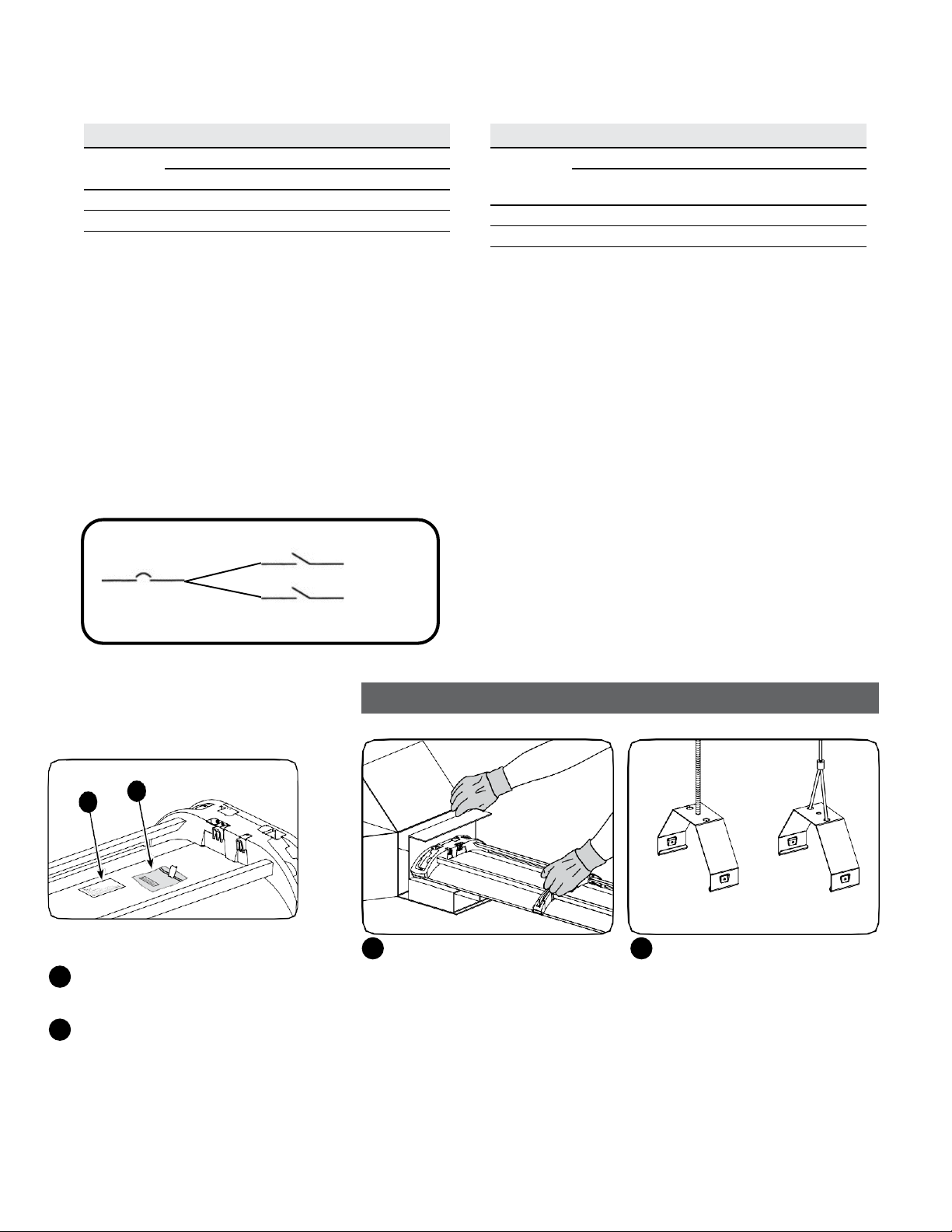
Identiftcation Label
Daintree Node identification label installed
1
on luminaire back reflector.
1
Remove package with smaller label. This label
2
is to beused for customer floor plan or records.
Circuit #1
Circuit #2
Installation of an Independent Unit (IS1)
Choose suspensionmethod
Carefully unpack unit and inspect for
1 2
defects before installing. Wear work
gloves to prevent dirt and oil from
being transferred to the luminaire.
NOTE: When installing luminaires use
clean gloves in order to avoid fouling
the reflective surface.
Attach mounting bracket to ceiling
support structure either directly or
using a GE suspension kit according
to the suspension kit instructions
(see page 2). Maximum distance
between suspensionpoints shall not
exceed the length of the luminaire.
3
ACline
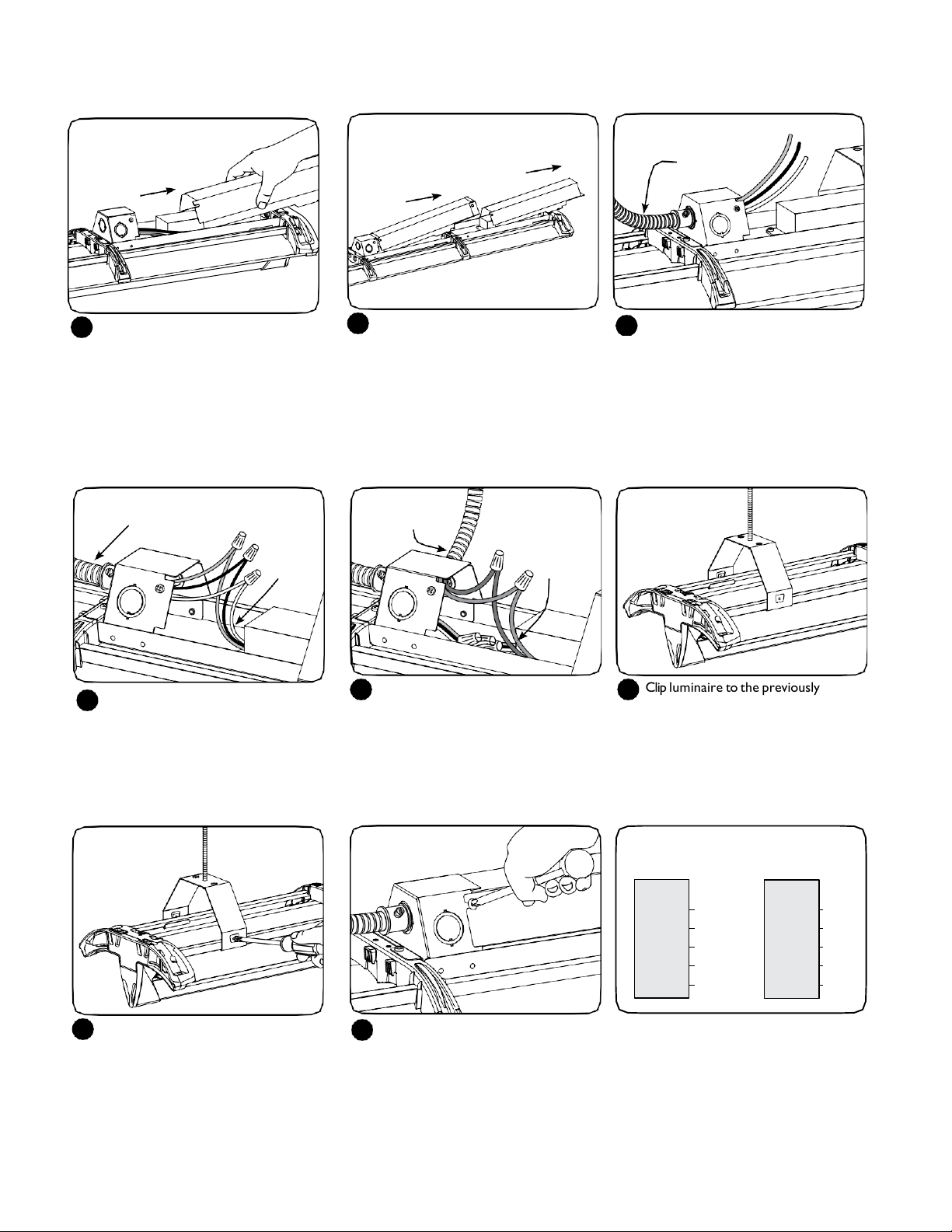
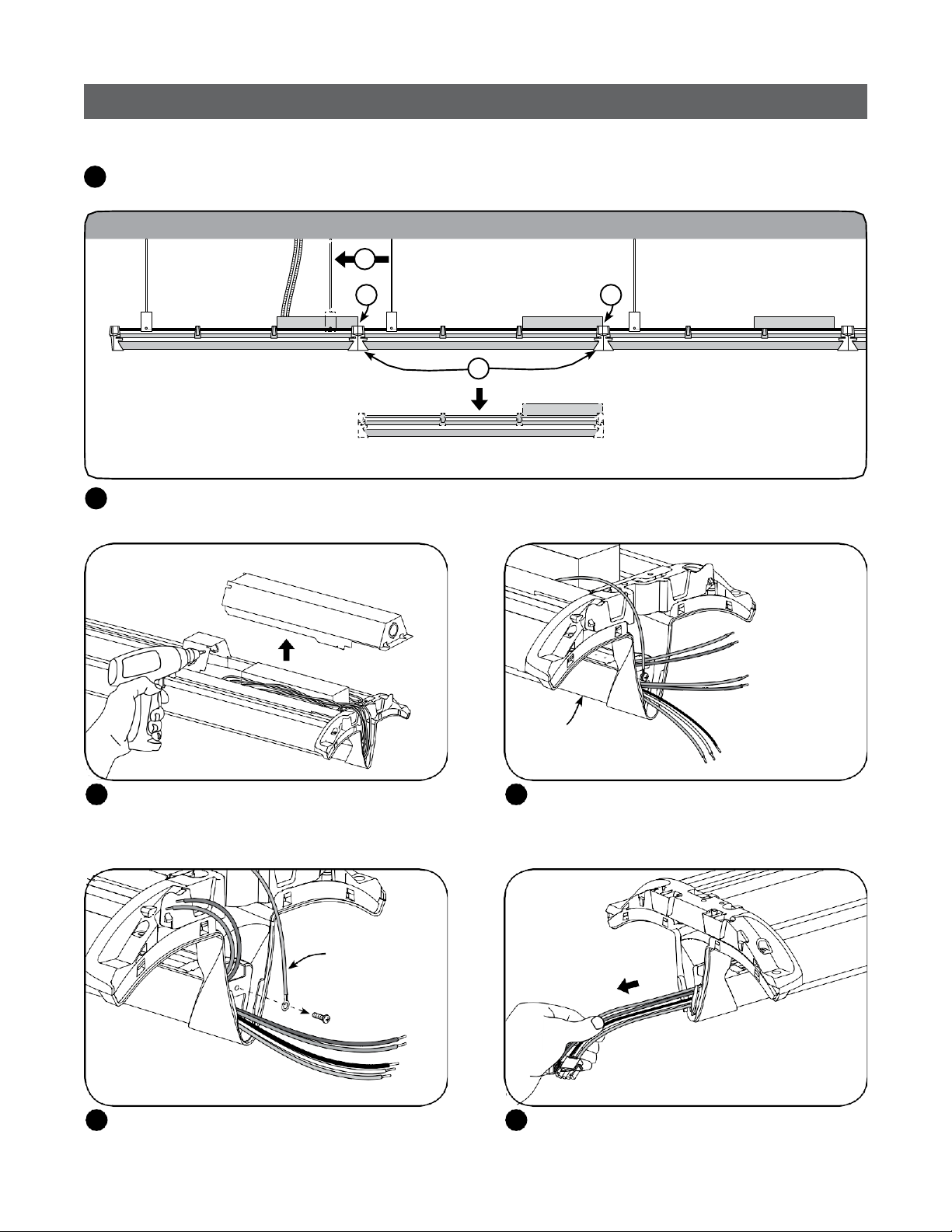
Prepare luminaire for installation
3
by loosening the PSU cover screws
and removing the cover.
ACline
Connect the green (ground), black
6
(line) and white (neutral) wires of
the AC line to the similarly colored
wires of the power supply unit using
separate UL listed wire nuts.
PSU
wires
For 347V ftxture: Loosen PSU cover
4
screws and remove two covers.
Dimming line
(optional)
Dimming
wires
Optional dimmer: Install UL listed
7
electrical fitting and insert dimming
control wires through. Connect
dimming control wires (grey and violet
for 0-10V or violet and violet/white strip
for DALI) to the similarly colored fixture
wire using separate UL listed wire nuts.
Carefully remove appropriate knockout
5
for AC line input wires (inner knockout
for ½”conduit, outer knockout for
¾” conduit). Install listed electrical
fittings in the knockoutholes for wire
protection and pass supply conduit
through electrical fittings.
Clip luminaire to the previously
8
installed mountingbrackets.
Fix the mounting position and secure
9
the suspension by tightening the two
screws on both mountingbrackets.
Replace power supply cover(s) by
10
sliding over the captive screws and
secure by tighteningthem.
Note: When installation iscomplete,
all lead wires and connectors shall
be totallyenclosed.
4
DALI
Fixture
Line
Neutral
Ground Green
DALI Violet/White
DALI Violet
Wiring Diagrams
0-10V
Fixture
Black
White
Neutral
Ground
(0-10V)+
(0-10V)–
Line
Black
White
Green
Violet
Grey
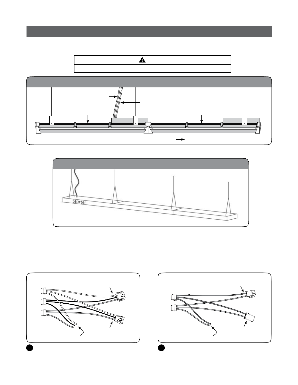
Installation of a Continuous Row using a Starter Kit
Use starter kits as a convenient way to install continuous rows. Starter kits are ordered separately (SKU 93018007provides parts for
1 continuous row, SKU 93022791 provides parts for 10 continuous rows).
CAUTION
THERE IS A REqUIRED DIRECTION FOR ASSEMBLING A CONTINUOUS ROW.
Ceiling
ACline
First fixture in
the row
Direction of continuous row installation
Continuous runs must begin with a first unit that is suspended at both ends. Use provided end-caps from starter kits to begin and
terminate the row.
The Starter & Continuous Run fixtures connect in rows
Dimming line
(optional)
Next fixture in
the row
As the name implies, the Starter (if your product has such a choice) contains the beginning of the electrical connection.
This means that this fixture has the onl
y Power Drop.
The starter, when suspended, also is normally the only fixture in the row with (2) suspension hangers.
The rest of the run may be suspended from a single hanger (positioned near the end where the next fixture will connect).
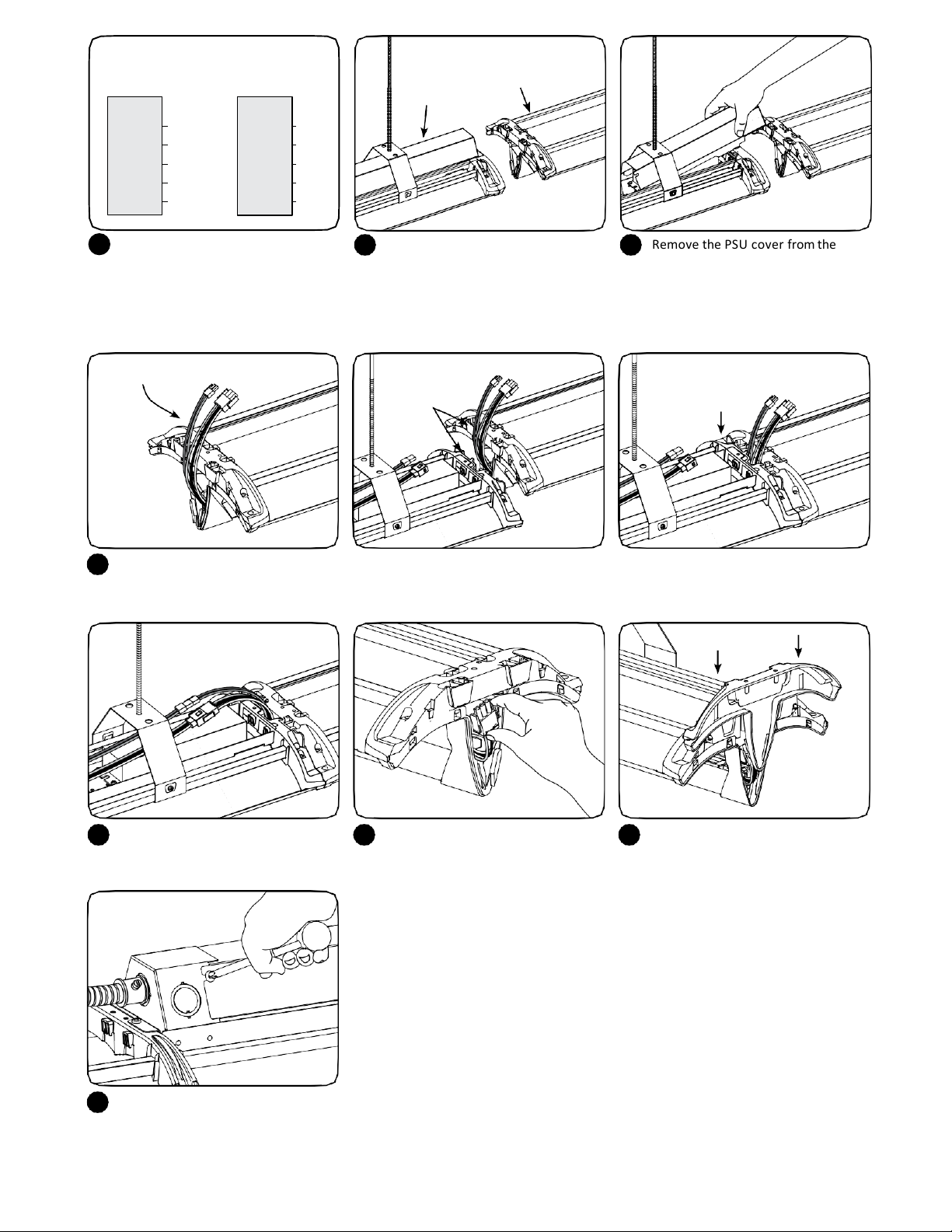
For mechanical installation, follow steps 1-6 described earlier in these install instructions.
Connectto power harness in
driverenclosure
Connect to AC line using
separateUL listed wire nuts
Use provided starter power harness as an extension
1
for the first fixture in the row.
Connectto next fixture in
continuous row
Connect to dimmingline
(optional) using separate
UL listed wirenuts
A dimming starter harness is provided to optionally
2
connect the dimming through wiring to the dimming line.
5
Connect to dimmingharness
in driverenclosure
Connectto next fixture in
continuous row
DALI
Fixture
Line
Neutral
Ground Green
DALI Violet/White
DALI Violet
Wiring Diagrams
0-10V
Fixture
Black
White
Neutral
Ground
(0-10V)+
(0-10V)–
Line
Black
White
Green
Violet
Grey
Previously
hung unit
Newunit
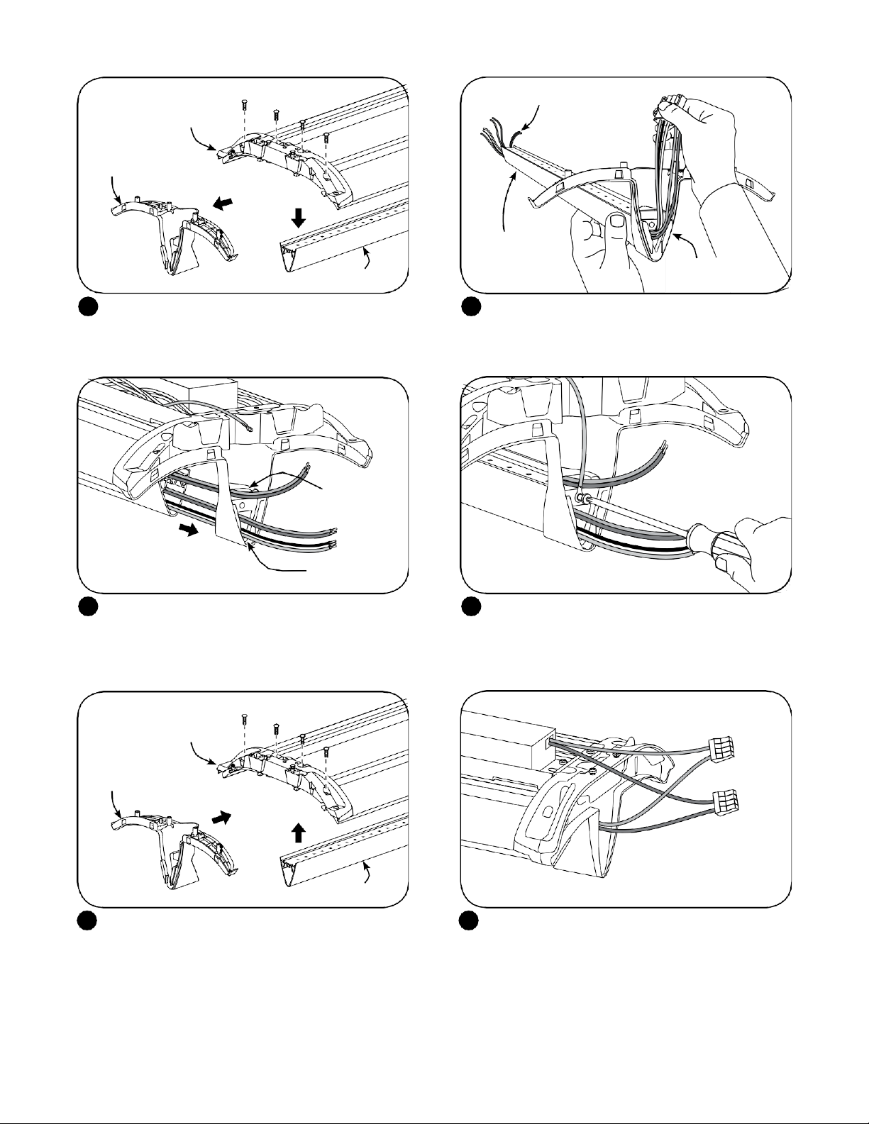
3
Toadd a continuous unit to a c
4
ontinuous
Remove the PSU cover from the
5
5
previously hung luminaire if present. run, first suspend the new unit as it is done
in steps9 and 10 for the independent unit.
Position the non-power-supply end of the
luminaire near the power-supply end of
the previously hung luminaire.
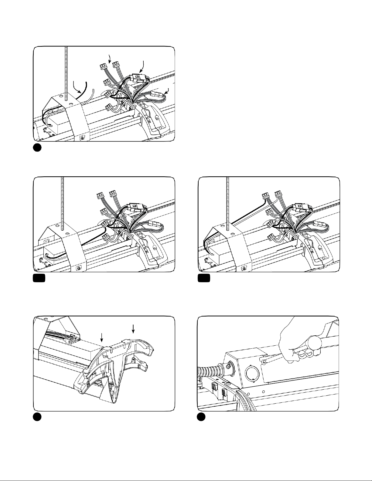
Pull out continuous wiring
Pull the continuous wiring out of the luminaire being mounted and slide the bridge of the luminaire down onto the bridge of the
6
Aligntabs
with slots
Pushdown
to engage
already installed luminaire so that the tabs and slots at top and bottom nest into one another. The bridges will engage with a
loud click whenfully mated.
Connect the power and control
7
connectors of the through wiring
harness.
Replace the PSU cover(s) and secure
10
using the mounting screws.
Note: When installation is complete,
all lead wires and connectors shall be
totally enclosed.
At the beginning of the row, push the
8
wiring inside the cavity of the bridge.
6
Clip one end-cap at the beginning
9
of the row and one at the end
(provided in the starter kits).

Installation of a Continuous Row with Optional BranchCircuit
CAUTION
THERE IS A REqUIRED DIRECTION FOR ASSEMBLING A CONTINUOUS ROW.
Ceiling
ACline
First fixture in
the row
Direction of continuous row installation
For mechanical installation, follow steps 1-6 described earlier in these installinstructions.
Dimming line
(optional)
Next fixture in
the row
AC from 1st circuit
Carefully remove appropriate knockout for AC line input
1
wires (inner knockout for ½” conduit, outer knockout
for ¾” conduit). Install listed electrical fittings in the
knockout holes for wire protection and pass supply
conduit through electrical fittings.
Starter harness
1st circuit connection: Connect the green (ground),
2
black (line) and white (neutral) wires of the AC line to
the similarly colored wires of the starter harnessusing
the provided push-in wire nuts (starter unit) or connect
using wire nuts if using a starter kit (see above).
7

Dimming line
(optional)
First circuitwires
Dimming
connections
Second circuitwires
Brown, Brown/white stripewires
Optional dimmer: Install UL listed electrical fitting and
3
insert dimming control wires through. Connect dimming
control wires (grey and violet for 0-10V or violet and
violet/white stripe for DALI) to the similarly colored
fixture wires using the provided push-in wire nuts
(starter unit) or using wire nuts (starter kit).
2nd circuit connection: Install listed electrical fittings in
4
the second knockout holes for wire protection and pass
supply conduit through electrical fittings. The second
circuit wires (line and neutral) will be connected to the
second luminaire in the continuous run. Leave them
unconnected to the brown and brown/white stripe wires
fornow.
Purple, grey
Brown, brown-white
Pull out
continuous
wiring
Pull the continuous wiring out of the next luminaire being mounted and slide the bridge of the luminaire down onto the bridge of
5
Green, black,white
Align tabs
with slots
Pushdown
to engage
the already installed luminaire so that the tabs and slots at top and bottom nest into one another. The bridges will engage with a
load click when fully mated.
Brown
Connect the power and control connectors of the
6
Brown/white stripe
through wiring harness. Connect AC Circuit #1 (black,
white and green harness) from first fixtureto AC Circuit
#1 from second fixture.Connect AC Circuit # 2 (brown
and brown/white stripe harness) from first fixture to
AC Circuit #2 from second fixtureand connect second
circuit supply lines of starter unit.
Wiring Diagrams
Circuit
#1
Circuit
#2
DALI
Fixture
Neutral
Neutral
Ground
Line
Line
DALI
DALI
Black
White
Brown
Brown/white
Green
Violet/White
Violet
Circuit
#1
Circuit
#2
0-10V
Fixture
Neutral
Neutral
Ground
Line
Line
0-10V
0-10V
Black
White
Brown
Brown/white
Green
Violet
Grey(18 AWG)
8
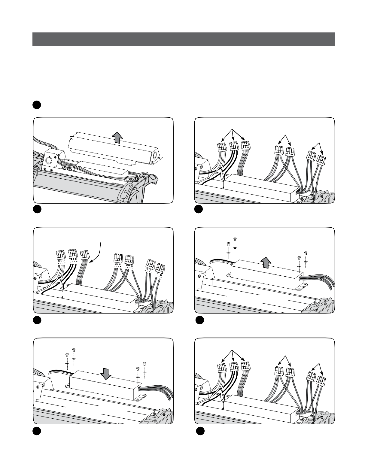
Connecting a Unit to AC Circuit #1 or AC Circuit #2
AC Circuit #2
Black and
white wires
PSU
Locate the black (line) and white (neutral) wires on the
7
PSU. Pull the wires out of the box to have good access.
AC Circuit #1
AC Circuit #1 Connections AC Circuit #2 Connections
AC Circuit #1
Dimming
AC Circuit #2
Connect the black (line) and the white (neutral) wires
8A 8B
of the PSU to the AC lines similarly colored wires using
the push-inwire nuts.
To terminate a mechanical run take the end cap from
9
the starter luminaire or starter kit and clip down onto the
last bridge.
10
Connect the black (line) of the PSU with the brown (line)
AC wire using the push-in wire nut. Connect the white
(neutral) wire of the PSU with the brown/white (neutral)
AC wire using the push-in wire nut.
Replace the PSU cover(s) and secure using the mounting
screws.
Note: When installation is complete, all wiring and
connectors shall be totally enclosed.
9
PSU Replacement Procedure
Tools and Parts Required:
• New power supply unit (PSU)
• Wire cutter
• T15 Torx or Phillips #2screwdriver
• UL approvedwire connectors (4-pin)
Disconnect the luminaire power source.
1
Mounting bracket not shown for clarity
Loosen 3 screws and remove the PSU cove r.
2
Do not cut greenAC wires
AC
Locate the DC (red and blue), AC (green, white and
3
black) and Dimming connections (purple and gray).
Remove oldPSU
Other wires hiddenfor clarity
Dimming
DC
Cut the original DC, AC (do not cut the green wire)
4
and Dimmingconnections.
Install new PSU
Other wires hiddenfor clarity
Install the new PSU using a star washer under
6
each screw.
10
Unscrew the old PSU and remove.
5
AC
Reconnect the DC, AC, and Dimming wires using
7
UL approved connectors. Reattach the PSU cover.
Dimming
DC
Light Engine Replacement Procedure
For optical codes A, B, E, F, G, J, K, M, N, P, R, S
Disconnect the luminaire power source.
1
1
2 2
Ceiling
1. Move suspension point to avoid
cantilever effect.
2. Remove 2 screws onPSU cover.
Disconnect wires to adjacent
fixtures.
3. Unsnapboth ends.
Remove fixture from ceiling.
2
Unscrew and remove the PSU cover. Locate AC, DC and dimming wires coming from
3 4
3
Fixture toreplace
Heatsink
DC wires
(blue/red)
Dimming wires
(grey/purple)
AC wires
(black/white/green)
heatsink and cut or disconnect them (other wires
not shown for clarity).
Remove ground screw and wire.
5
Groundwire
11
Pull out the thru wiring from the opposite en d.
6
Save wiring forlater.
Upper
bridge
Lower
bridge
Light engine
Remove 4 screws to detach upper bridge from
7
lower bridge and replaceable light engine.
(blue/red wires)
Top hole
Blue/red wiring
New light
engine
Pull thru wiring (saved from Step 6) through the
8
Wires exitbottom
hole of bridge
new light engine and lower bridge.
Bottomhole
(thruwiring)
At PSU side, insert light engine into bottom bridge.
9
Blue/red wiring passes through the top hole. Thru
wiring passes through the bottom hole.
Upper
bridge
Lower
bridge
Light engine
Reassemble the upper and lower bridge to the
11
fixture with 4 screws.
Reattach the ground wire and screw.
10
DCwires
(blue/red)
Reconnect DC wires according to color (other wires
12
not shown for clarity).
12
AC wires
(black/white/green)
Dimming wires
(grey/purple)
Reconnect thru wires according
13
to color (other wires not shown
for clarity).
Push wires into tray and
14
reattach cover.
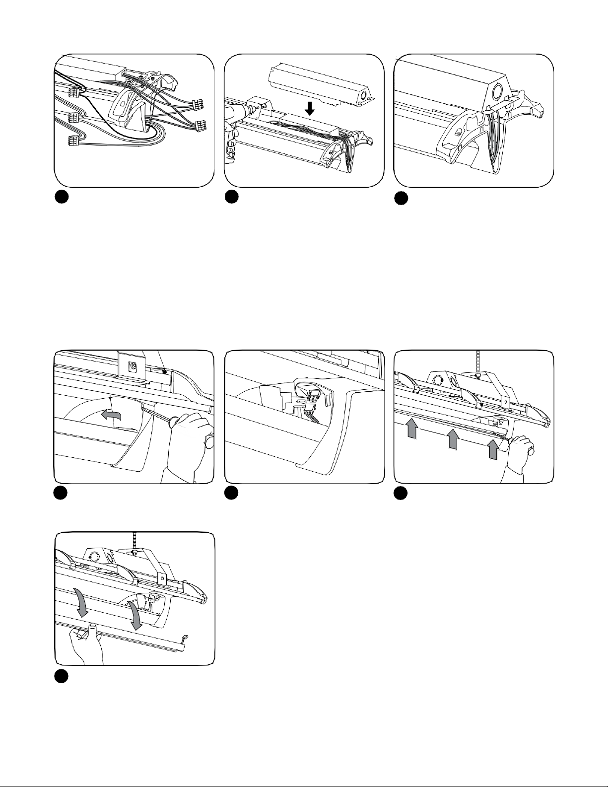
How To Replace Light Engine in the Field
For LumenCode [42][52][84][A0] Only
Make sure no wires are pinched.
15
NOTE: Make sure all wires and
connectors and are properly
enclosed.
With a flathead screwdriver,
1
open accessdoor.
Remove heatsink. Reverse steps
4
to install the new light engine.
Disconnect DC power.
2
13
With a flathead screwdriver,
3
unsnap clip near the end.
Continueunsnapping
remaining clips.
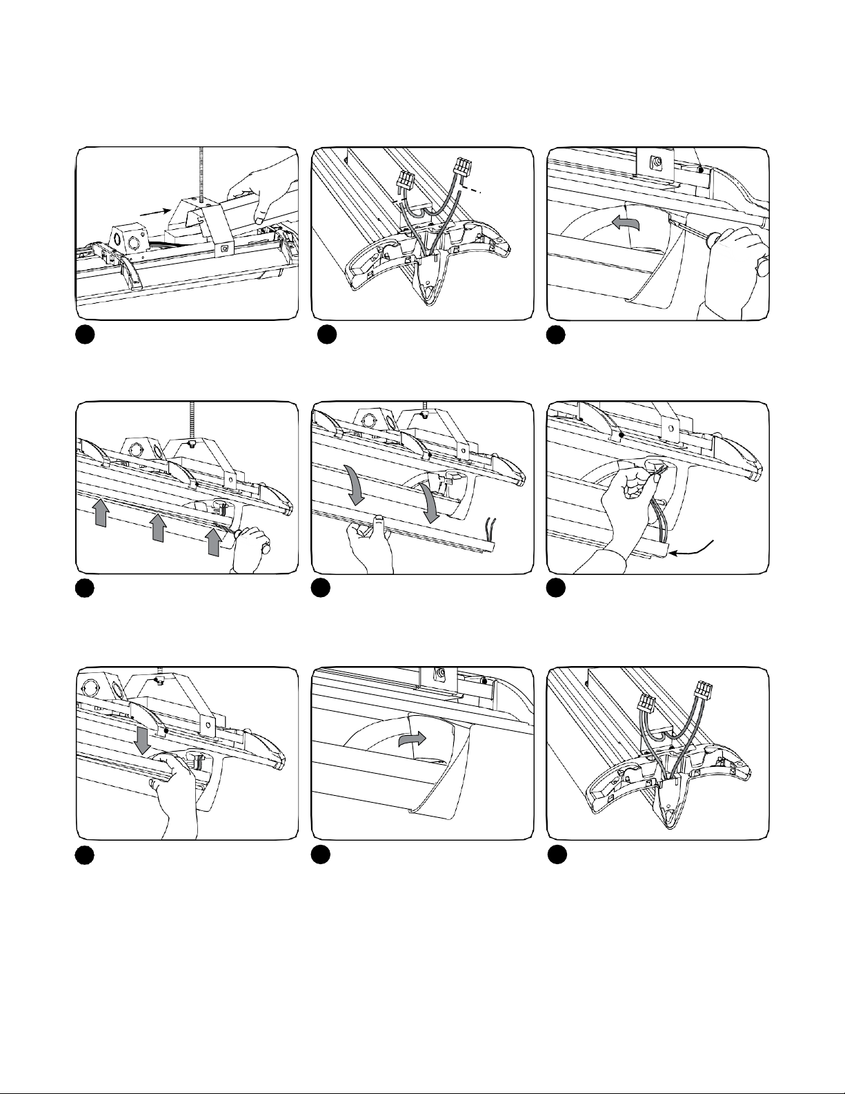
How To Replace Light Engine in the Field
For LumenCode [65][85][A3][A7][A1][A2][B1][B4] Only
TURN OFF POWER. Remove PSU
1
cover.
With a flathead screwdriver,
4
unsnap clip near the end. Continue
unsnapping remaining clips.
Cut blue and red wires from
2
light engine (other wires hidden
for clarity).
Remove removeable light engine.
5
With a flathead screwdriver, open
3
access door.
New light
engine
Take the red and blue wires of the
6
new light engine and fish them
through opening.
Clip removeable light engine into
place.
Close the access door. Reconnect blue and red wires
8 97
from the new light engine (other
wires hidden for clarity). Reinstall
PSU cover.
14

Troubleshooting
Symptom
Luminaires will not turn on
Luminaire on through wiring
will not turn on
Luminaire to luminaire mating
in continuous run is loose
Suspension methodwon’t
engage with luminaire
Solution
• Check that the c
• Check that the LED driver connector is fully engaged to the LED light engine connector.
• Check that the t
engaged to the malfunctioning luminaire.
• Ensure that bot
• Ensure that through wires are correctly routed in the wiring notch.
• Check that the suspension method is one of the approved types in the installation instruction.
olor of the supply side wires match the color of the wires they are connected to.
hrough wiring connector from the previous fixturein the linear row is fully
h upper and lower connecting features are correctly engaged.
This device complies with Part 15 of the FCC Rules. Operation is subject to the following two conditions: (1)This device may not cause harmful interference,
and (2) this device must accept any interference received, including interference that may cause undesired operation. This Class [A] RFLD complies with the
Canadian standard ICES-003.Ce DEFR de la classe [A] est conforme à laNMB-003 duCanada.
Note: This equipment has been tested and found to complywith the limits for a Class Adigital device, pursuant to part 15of the FCC Rules. These limits are
designed to provide reasonable protection against harmful interference when the equipment is operated in a commercial environment. This equipment
generates, uses, and can radiate radio frequency energy and, if not installed and used in accordance with the instruction manual, may cause harmful
interference toradio communications.Operation of this equipment in a residentialarea is likelyto cause harmful interference inwhich case the user will be
required to correct the interference athis own expense.
www.LED.com
and the GE Monogram are trademarks of the General Electric Company. All other trademarks are the property of their respective owners. Information
GE
provided is subject to change without notice. All values are design or typical values when measured under laboratory conditions. GE Lighting is a business of the
General Electric Company. ©2019 GE.
IND095-SPA-(Rev04/15/19)
GE2024-6981
15

Manuel d’installation
Luminaire LED Lumination
TM
(Séries I
S)
Il y a deux types d’appareils:
• Starter (Départ) (gammeISS)
• En continus(Séries ISC)
• Indépendant (SériesIS1)
Pour une situation générale, utilisez la trousse Starter (Départ).
Si désiré, utilisez l’UGS Starter (Départ).
AVANT DE COMMENCER
Lisez ces instructions entièrement et avec attention.
Notes importantes ci-dessous et à la page 3.
WARNING/AVERTISSEMENT
RISK OF ELECTRICSHOCK
• Turn power off before inspection, installation or removal.
• Properly ground electricalenclosure.
RISK OF ELECTRICSHOCK
• Follow all NEC and local codes.
• Use only UL approved wire for input/output connections.
Minimumsize 18 AWG or 14AWG for continuous runs.
• When using multi-branch wire circuits with a sharedneutral,do not
operate any circuit with the neutral open. Also ensure all neutral connections
are secure before energizing the circuit.An openneutral can cause an
overvoltage condition at the luminairepower supply.
• Lorsque vous utilisezdes circuits câblés à branches multiples avec un
RISQUES DE DÉCHARGESÉLECTRIQUES
• Coupez l’alimentation avant d’inspecter, installer ou déplacer le luminaire.
• Assurez-vous de correctement mettre à la terre le boîtier
d’alimentationélectrique.
RISQUESD’INCENDIE
• Respectez tous les codes NEC et codes locaux.
• N’utilisez que des fils approuvés par UL pour les entrées/sorties de
connexion. Tailleminimum 18AWG ou14 AWG pour les rangées continues.
neutre commun, ne mettez aucun circuit en service avec le neutre ouvert.
Assurez-vous également que tous les raccords neutres soit sécurisés avant
de mettre le circuit soustension. Un neutre ouvert peut causer une condition
de surtensionà l’alimentation du luminaire.
Conservez ces instructions
Àn’utiliser que de la manière prévue par le fabricant.
Si vous avez des questions, contactez le fabricant.
Préparation du câblage électrique
Conditions d’alimentation électrique
Cet appareil DEL doit être alimenté en 100-277
VCA , 50/60 Hz, ou 347 V, 50/60 Hz et protégé par
un disjoncteur de 20 Amax. Utilisez un conducteur
d’alimentation de 75°C min. Une alimentation en 347
V ne devrait être fournie aux luminaires qu’avec une
tension code“D”.
Instructions de mise à la terre
La miseà la terre et les raccordements de l‘ensemble
du système doivent être fait en accord avec l’article
600 du National Electric Code (NEC) et des codes locaux.
Composants fournis:
• Luminaire
• 2 supports de montage
• Capuchond’extrémité (2 capuchons avec les gammes IS1 etISS)
Remarque: En général,l’UGS Starter (Départ)n’est pas
nécessaire avec la trousse Starter (Départ).
Outils et composants requis:
• Tournevis hexalobéT15 ou Phillips No 2
• Raccords de conduits homologués UL suivant NEC/CEC pour
conduits dimensions nominales ½ po ou ¾ po
• Connecteurs homologués UL
Table of Contents Page
Trousses d’accessoires 17
Installation d’un appareil Independant(Autonome) (IS1) 18
Installation d’un segment continu au moyen d’une
trousse Starter (Départ)
Installation d’un segment continu au moyen d’un
circuit de dérivation facultatif
Remplacement dubloc d’alimentation 25
Procedure de replacement de la source lumineuse 26
19
21
16

Trousses d’accessoires (venduesséparément)
Trousses dedépart
93018007 - Trousse de départ (1 segment continu)
93022791
Utilisez-la pourconnecter un segment continu de luminairessur les
bornesd’alimentation
Supports de montage
- Trousse de départ (10 segmentscontinus)
94210 - Trousse standard(10 supports)
Utilisez-la si des supports supplémentaires reptation (10 supports)
sontnécessaires
93088000 - Trousse de prévention dela
Utilisez-la si la géométrie de l’installation
nécessite un point de montage jusqu’à un pouce
hors de l’axe du segment continu
Trousses desuspension
210221 - Trousse de connexion de joints
supports)
(5
Utilisez-la si la géométrie de l’installation
nécessite un point de montage directement
au-dessus du luminaire ou de la jonction du
luminaire
93026986 - Trousse de montage supérieure (emballage de 2)
Utilisez-la pour fournir un point d’ancrage de montage sur un
plafondfini
93026985 - Trousse de montage inférieure (emballage de 2)
Utilisez-la pour suspendre le luminaire jusqu’à 3 m (10 pi)
sous la structure fixe ou la trousse de montage supérieure
93026987 - Trousse d’auvent d’alimentation (emballage de 1) Utilisezla pourcouvrir la boîte de jonction exposée pourles applications à
montage suspendu
17

IMPORTANT - Longueur maximale du circuitélectrique
IS de première génération IS de deuxième génération
Code Lumen CodeLumen
Tension A E,G,S ou J B,F ou K M,N,P ou R U,V,W ou X
120V 59 m (192 pi) 49 m (160 pi) 24,5 m (80 pi) 18,3 m (60pi)
277V or 347V 123 m (400 pi) 98 m (320 pi) 58 m (188 pi) 40,2 m (132 pi)
• Consultez la fiche technique pour connaître les propriétés
électriques et assurer une installation sécuritaire.
• Pour les types A, G, J, B, F, K ou E, la tension maximum du
circuit d’attaque desluminaires branchés nepeut en aucun
cas être supérieure à 15 A.
• Pour les types M, N, P ou R, latension maximum du circuit d’attaque
des luminaires branchés ne peut en aucun cas être supérieure à 12 A.
Les luminaires de la gamme IS sont offerts en deux versions : unités continues (série ISC) et unités indépendantes (série IS1).
Un circuit électrique continu sera composé d’un nombre d’unités continues jusqu’àune tension maximale indiquée ci-dessus. Lors
de l’installation des luminaires, portez des gants proprespour éviter de salir la surface réfléchissante. Pour ne pas salir l’appareil,
installez-le entouré d’un sac plastique, puis ôtez le sac plastique lorsque toutes les activités liées à la construction sont terminées.
Si deux circuits supplémentaires sont inclus dans le luminaire, ils doivent être connectés en série au même
disjoncteur que le diagramme ci-dessous et le courant total ne doit pas dépasser un maximum de 15A ou 12A
(par commentaire ci-dessus).
1
2
Tension
120V 59 m (192 pi)
277V or 347V 123 m (400 pi) 98 m (320 pi) 58 m (188 pi) 40,2 m (132 pi)
• La tension maximum du circuit d’attaque des luminaires
branchés ne peut en aucun cas être supérieure à 15 Apour
les codes de Lumen [42], [52], [84], ou [A0].
• La tension maximum du circuit d’attaque des luminaires
branchés ne peut en aucun cas être supérieure à 12 Apour
les codes de Lumen [65], [85], [A3], [A7], [A1], [A2], [B1] ou [B4].
[42] [84] [52][A0]
49 m (160pi)
[65][85]
[A3][A7]
24,5 m (80pi) 18,3m(60 pi)
[A1][A2]
[B1][B4]
Breaker
Étiquette d’identiftcation
du nœud Daintree
Étiquette d’identification du nœud Daintree
1
installée sur le réflecteur
Enlevez l’emballage avec la plus petite étiquette.
2
Cette étiquette est destinée au plan d’implantation
du client ou pour ses archives.
arrière duluminaire.
Circuit #1
Circuit #2
Installation d’un appareil indépendant(IS1)
Choisissezla méthode de suspension
Déballez soigneusement l’unité et inspectez-
1
en cas de défauts avant l’installation. Portez
des gants detravail pouréviter de déposer de
la saleté ou de l’huile surle luminaire.
REMARQUE: Lors de l’installation des
luminaires, portez des gants propres pour
éviter de salir la surfaceréfléchissante.
Fixez le support de montage à la structure du
2
la
plafond, soit directement ou en utilisant une
trousse de suspension GE, conformément
aux directives quiaccompagnent la trousse
(voir page 2). La distance maximum entre
les points de suspension ne doit pas être
supérieureà la longueur duluminaire.
18

LigneCA
Préparez le luminaire pour son
3
installation en desserrant les vis du
couvercle de l’unité d’alimentation
et enl’enlevant.
LigneCA
Raccordez les fils vert (terre), noir
6
(ligne) etblanc (neutre) de la ligne
Fils de l’unité
d’alimentation
CA aux fils de mêmes couleurs
de l’alimentation en utilisant
des capuchonsde connection
homologués ULséparés.
Pour l’appareil 347V: Desserrez
4
les vis du couvercle de l’unité
d’alimentation et enlevez les deux
couvercles.
Ligne
gradateur
(en option)
gradateur
Gradateur optionnel: Installez un
7
raccord électrique homologué UL et y
insérez les fils du gradateur. Raccordez
les fils de contrôle de gradation (gris
et violet pour 0–10 V ou violet et
violet/bande blanche pour DALI) au
fils de l’appareil de mêmecouleurs en
utilisant des capuchonsde connection
homologués UL séparés.
Filsdu
Avec précaution enlevez la pastille
5
défoncable pour l’entrée des fils d’arrivée
de la ligne CA (pastille intérieure pour
conduit de ½”, pastille extérieure pour
conduits de ¾”). Installez les raccords
électriques spécifiés dans les trous
défoncés pour la protection des fils et
passez lesfils d’alimentation à travers les
raccords électriques.
Attachez le luminaire aux supports
8
de montage installés d’avance.
Décidez dela position de montage et
9
fixez l’attache suspendue en serrant
les deux vis sur les deux supports de
montage.
Remettez en place le(s) couvercle(s) de
10
l’alimentation en le(s) glissant sur les vis
imperdables et fixez-les en serrant les vis.
Remarque: Lorsque l’installation est
terminée, tous les fils d’alimentation et les
capuchons seront totalement enfermés.
19
Schémas de câblage
DALI 0-10V
Luminaire
Ligne Noir
Neutre Blanc
Mise à la terre Vert
DALI Violet/blanc
DALI Violet
Luminaire
Neutre Mise
àla terre (0-
(0-10V)–
Ligne
10V)+
Noir
Blanc
Vert
Violet
Gris

Installation d’un segment continu au moyen d’une trousse Starter(Départ)
Utilisez les trousses de départ pour installer des segments continus. Les trousses de départ sont vendues séparément (UGS 93018007
comprend les pièces pour 1 segment continu; UGS 93022791 comprend les pièces pour 10 segments continus).
ATTENTION
IL Y A UNE DIRECTION BIEN PRECISE POUR L’ASSEMBLAGE EN FILE CONTINUE.
Plafond
LigneCA
Premier appareil
dans la file
Sens d’installation en file continue
Ligne dugradateur
(en option)
Appareil suivant
dans la file
Les files continues doivent commencer par un premier appareil qui est suspendu des deux cotés. Utilisez les couvercles d’extrémités
des kits de départ pour commencer et terminer la file.
L’appareil de départ et ceux d’un segment continu se connecte en rangé
Comme le nom l’indique, l’appareil de départ (si votre produit a cette option) contient les connexions électriques de
départ. Ce qui veut dire que cet appareil et le seul à être connecté à la ligne AC.
L’appareil de départ (lorsque suspendu) est aussi le seul à utiliser 2 attaches de suspension. Le reste des appareils d’un
segment continu peut utiliser une seul attache de suspension (positionnée vers la fin de l’appareil continu, là où le
prochain appareil sera connecté).
Pour l’installation mécanique, suivez les étapes 1 à 6 décrites précédemment dans ces directives.
Raccordez au harnais d’alimentation
dans le boîtier de l’alimentation
Raccordez à la ligneCA avec
des capuchonsde connection
homologués ULséparés
Utilisez le harnais d’alimentation de départ comme
1
extension pour le premier appareil dans la file.
Raccordez à l’appareil
suivant en file continue
20
Raccordez à la
ligne du gradateur
(en option)avec des
capuchons deconnexion
homologués ULséparés
Un harnais de départ du gradateur est fournis pour
2
raccorder, en option, par câblage vers la ligne du gradateur.
Raccordez le harnais du gradateur
dansle boîtier d’alimentation
Raccordez à l’appareil suivant
dans lafile continue

Schémas de câblage
DALI
Appareil
Ligne Noir
Neutre Blanc
Terre Vert
DALI Violet/Blanc
DALI Violet
0-10V
Appareil
Ligne
Neutre
Terre
(0-10V)+
(0-10V)–
Noir
Blanc
Vert
Violet
Gris
Appareildéjà
pendu
Nouvelappareil
Pour ajouter un appareil en continuation
3
Retirez les fils continus
Retirez les fils continusdu luminaire en cours de montage et glissez le pont du luminaire vers le bas sur le pont du luminaire déjà
6
4
d’une file, suspendez d’abord le nouvel appareil
tel qu’aux étapes 9
indépendant. Mettez en position l’extrémité
non alimentée du luminaire près de l’extrémité
alimentée du luminaire déjà suspendu.
Alignez lesonglets
avec lesrainures
et 10 pour un appareil
5
Le cas échéant, enlevez le couvercle
5
de l’unité d’alimentation du
luminaire déjà suspendu.
Poussez vers le bas
pouremboîter
installé de manière que les onglets et les rainures du dessus et du dessouss’engagent les unesdans les autres. Les ponts vont
s’emboîter avec un clic sonore lorsqu’ils s’engagent à fond.
Raccordez les prises d’alimentation et
7
de contrôle du harnais de passage.
Remettez en place le(s) couvercle(s)
10
de l’unité d’alimentation et fixez-le(s)
avec les vis demontage.
Remarque: Lorsque l’installation est
terminée tous les fils et connecteurs
seront entièrement enfermés.
Au débutde la file, poussez les fils à
8
l’intérieur de la cavitédu pont.
21
Engagezun couvercle d’extrémité
9
au début de la file et un à la fin
(fournis avec les kits de départ).

Installation d’un segment continu au moyen d’un circuit de dérivation facultatif
ATTENTION
IL Y A UNE DIRECTION BIEN PRECISE POUR L’ASSEMBLAGE EN FILE CONTINUE.
Plafond
LigneCA
Premier appareil
dans la file
Sens d’installation en file continue
Ligne dugradateur
(en option)
Appareil suivant
dans la file
Pour l’installation mécanique, suivez les étapes 1 à 6 décrites précédemment dans ces directives.
Alimentation CA du premiercircuit
Faisceaude départ
Retirez avec soin les disques défonçables pour les fils
1
d’alimentation CA (disques intérieurs pour conduits de
12,5 mm [½ po], disques extérieurs pour conduits de
19,0 mm [¾ po]). Installez les raccords électriques dans
les trous des disques pour protéger les fils, puis faites
passer les fils dans ces raccords.
22
Branchement du premier circuit: Branchez les fils vert (mise à
2
la terre), noir (sous tension) et blanc(neutre) de l’alimentation CA
aux fils de couleurs similaires du faisceau de départ au moyen
de capuchons de connexion enfonçables (unité de départ) ou
branchez-les en utilisant des capuchons de connexion si vous
utilisez une trousse de départ (voir ci-dessus).

Gradation del’intensité
(facultatif)
Connexionsde
gradation de
l’intensité
Fils du premier circuit
Fils du deuxième circuit
Fils brun, brun/bandesblanches
Gradateur facultatif: Installez un raccord électrique
3
homologué UL, puis faites-y passer les fils du gradateur.
Branchez les fils de commande du gradateur(gris et violet
pour une tension de 0 à 10 V ou violet et violet/bandes
blanches pour le type DALI) aux fils de couleurs similaires
du luminaire au moyen de capuchons de connexion
enfonçables fournis (unité de départ) ou en utilisant des
capuchons de connexion (trousse de départ).
Pourpre/gris
Brun,brun-blanc
Faites passerles
fils d’alimentation
du segment
continu
Sortez les fils d’alimentation continu du prochain luminaire en cours d’installation et faites glisser le pont du luminaire sur le pont
5
Vert, noir,blanc
Alignez les
pattes avec
les rainures
Branchement du second circuit: Installez les raccords
4
électriques dans les trous des disques du second
compartiment pour protéger les fils, puis faites passer
les fils dans ces raccords. Les fils du deuxième circuit
(sous tension et neutre) seront branchés au second
luminaire du segment continu. Laissez-les sans
branchement avec les fils brun et brun/bandes blanches
pour le moment.
Poussezpour
enclencher
du luminaire déjà installé, de sorte que les pattes et les rainures dans le haut et le bas s’enclenchent les unes dans les autres.
Une fois bien enfoncés, les ponts émettent un fort “clic”.
Brun
Branchez les connecteurs de fil d’alimentation et de
6
Brun/bandes
blanches
commande dans le faisceau de câbles.Branchez le circuit
CA n° 1 (faisceau de fils noir, blanc et vert) du premier
luminaire au circuit CA n° 1 du second luminaire. Branchez
le circuit CA n° 2 (faisceau de fils brun et brun/bandes
blanches) du premier luminaire au circuit CA n° 2 du
deuxième luminaire et branchez les fils d’alimentation du
deuxième circuit de l’unité de départ.
23
DALI
Luminaire
Circuit
n°1
Circuit
n°2
Mise à la terre
Schémas decâblage
Noir
Ligne
Blanc
Neutre
Ligne
Brun
Neutre
Brun/blanc
Vert
DALI
Violet/blanc
DALI
Violet
0-10V
Luminaire
Circuit
n°1
Circuit
n°2
Mise à la terre
Ligne
Neutre
Ligne
Neutre
0-10V
0-10V
Noir
Blanc
Brun
Brun/blanc
Vert
Violet
Gris (18AWG)

Branchement d’un appareil au circuit CA n° 1 ou au circuit CA n° 2
Circuit CA n° 2
Fils noiret
blanc
PSU
Localisez les fils noir (sous tension) et blanc (neutre) du bloc
7
d’alimentation. Tirez les fils hors du boîtier pour y avoir
facilementaccès.
Circuit CA n° 1
Gradation
l’intensité
Connexions du circuit CA n° 1
Circuit CA n° 1
de
Connexions du circuit CA n° 2
Circuit CA n° 2
Branchez les fils noir (sous tension) et blanc (neutre) du
8A 8B
bloc d’alimentation aux fils de couleurs similaires de
l’alimentation CA au moyen de capuchons de connexion
enfonçables.
Pour terminer le segment mécanique, prenez le
9
capuchon d’extrémité du luminaire de départ ou de la
trousse de départ et enclenchez-le sur le dernier pont.
10
Branchez le fil noir (sous tension) du bloc d’alimentation
au fil CA brun (sous tension) au moyen d’un capuchon
de connexion enfonçable. Branchez le fil blanc (neutre)
du bloc d’alimentation au fil CA brun/blanc (neutre) au
moyen d’un capuchon de connexion enfonçable.
Remettez le couvercle du bloc d’alimentation en place,
puis fixez-le au moyen des vis de montage.
Remarque: Une fois l’installation terminée, tous les
fils et les connecteurs doivent être à l’intérieur du
compartiment.
24

Procédure de remplacement du blocd’alimentation
Outils et pièces nécessaires:
• Nouveau bloc d’alimentation
• Coupe-fil
• Tournevis Phillips n° 2 ou de type Torx T15.
• Capuchons de connexion (à 4 broches) approuvés UL
Débranchez la source d’alimentation du luminaire.
1
Supportde montage non illustré par souci de clarté
Desserrez les 3 vis et retirez le couvercle du bloc
2
d’alimentation.
Ne coupezpas les fils CA verts
CA
Localisez les connexions CC (rouge et bleu), CA (ver t, blanc
3
Gradation del’intensité
CC
et noir) et de gradation de l’intensité (pourpre et gris).
Retirez le vieux bloc
d’alimentation
Les autres fils sont
masqués par souci de clarté
Coupez les connexions originales CC, CA (ne
4
coupez pas le fil vert) et de réglage de l’intensité.
Installez le nouveaubloc
d’alimentation
Les autres fils sont
masqués par souci de clarté
Installez le nouveau bloc d’alimentation en
6
installant une rondelle en étoile sous chaque vis.
25
Dévissez le vieux bloc d’alimentation, puis retirez-le.
5
CA
Rebranchez les fils CC, CA et de gradation de l’intensité
7
Gradation del’intensité
au moyen de connecteurs approuvés UL. Remettez le
couvercle du bloc d’alimentation en place.
CC

Procedure de replacement de la sourcelumineuse
Pour les codes optiques A, B, E, F, G, J, K, M, N, P, R, S
Débranchez la source d’alimentation du luminaire.
1
Plafond
1
2 2
1. Déplacez le point de suspensionpour éviter
l’effet de poutre en porte-à-faux.
2. Retirez les 2 vis du couvercle du bloc
d’alimentation. Débranchez les fils des
luminaires adjacents.
3. Déclenchez les deux extrémités.
Retirez le luminaire du plafond.
2
Dévissez le couvercle du bloc d’alimentation,
3 4
Luminaire à remplacer
3
puis retirez-le.
Fils CC
(bleu/rouge)
Fils degradation
de l’intensité
(gris/pourpre)
Dissipateurde
chaleur
Fils CA
(noir/blanc/vert)
Localisez les fils CA, CC et de gradation de l’intensité
provenant du dissipateur de chaleur, puis coupez ou
débranchez-les (les autres fils ne sont pas illustrés
par souci de clarté).
Retirez la vis et le fil de mise à la terre.
5
Fil de mise à la terre
26
Tirez sur les fils d’alimentation par l’autre extrémité
6
pour les retirer. Conservez les fils pour plus tard.

Pont
supérieur
Pont
inférieur
Source lumineuse
Retirez les 4 vis pour détacher le pont supérieur du
7
pont inférieur et de la source lumineuse.
Trou du haut
(filsbleu/rouge)
Fil bleu/rouge
Nouveau
source
lumineuse
Faites passer les fils d’alimentation (mis de côté à
8
Les fils sortent du
trou au bas du pont
l’étape 6) dans le nouveau source lumineuse, puis
dans le pont inférieur.
Trou du bas
(filsd’alimentation)
Du côté du bloc d’alimentation, insérez le source
9
lumineuse dans le pont inférieur. Les fils bleu/rouge
passent par le trou du haut. Les fils d’alimentation
passent par le trou du bas.
Pont
supérieur
Pont
inférieur
Source lumineuse
Remettez les ponts supérieur et inférieur en place
11
sur le luminaire au moyen des 4 vis.
Remettez en place le fil de mise à la terre et la vis.
10
Fils CC
(bleu/rouge)
Rebranchez les fils CC en respectant le code de
12
couleur (les autres fils ne sont pas illustrés par
souci de clarté).
27

Fils CA
(noir/blanc/vert)
Fils de gradation
de l’intensité
(gris/pourpre)
Rebranchez les fils d’alimentation
13
en respectant le code de couleur
(les autres fils ne sont pas illustrés
par souci de clarté).
Repoussez les fils dans la
14
rainure, puis remettez le
couvercle en place.
Replacement de la source lumineuse sur leterrain
Pour les codes de Lumen [42] [52] [84] [A0] seulement
Assurez-vous de nepincer aucun fil.
15
REMARQUE: Assurez-vous que
tous les fils et les connecteurs
sont bien insérés dans le
compartiment.
Avec un tournevis à tête plate,
1
ouvrez laporte d’accès.
Retirez le dissipateur de chaleur.
4
Inversez les étapes pour installer
le nouveau source lumineuse.
Couper l’alimentationCC.
2
28
Avec un tournevis à tête
3
plate, ouvrez la pince près de
l’extrémité. Continuez à ouvrir
les pinces restantes.

Procedure de replacement de la source lumineuse surle terrain
Pour les codes de Lumen [65] [85] [A3] [A7] [A1] [A2] [B1] [B4] seulement
METTRE HORS TENSION. Retirez le
1
couvercle du bloc d’alimentation.
Avec un tournevis à tête plate,
4
ouvrez la pince près de l’extrémité.
Continuez à ouvrir les pinces
restantes.
Coupez les fils bleu et rouge de la
2
source lumineuse (les autres fils
sont masqués par souci de clarté).
Enlevez l’alimentation démontable.
5
Avec un tournevis à tête plate,
3
ouvrez laporte d’accès.
Prenez les fils rouge et bleu du
6
nouveau source lumineuse et
enfilez-les dans l’ouverture.
Nouveau
source
lumineuse
Réengagez en place l’alimentation
démontable.
Fermez la porte d’accès. Rebranchez les fils bleu et rouge
8 97
du nouveau source lumineuse (les
autres fils sont masqués par souci
de clarté). Réinstallez le couvercle
dubloc d’alimentation.
29

Recherche des Pannes
Symptôme
Le luminaire ne s’allume pas
Le luminaire sur câblage de
connexion ne s’allume pas
L’emboîtement de luminaire
à luminaire dans une file en
continu estlâche
Le système de suspensionne
s’enclenche pas auluminaire
Solution
• Vérifiez que la co
fils auxquelsils sont connectés.
• Vérifiez que le connecteur de la commande LED soit bien engagé avec le connecteur de
l’alimentation LED.
• Vérifiez que le con
correctement emboîté dans le luminaire défectueux.
• Assurez-vous que les de
• Assurez-vous que les fils de passage soient acheminés correctement dans leurs rainures.
• Vérifiez que la mé
d’installation.
uleur des fils du coté alimentation soient en concordance avec la couleur des
necteur du fil de passage de l’appareil précédent dans une file soit
ux éléments de connection, haut et bas, soient correctement engagés.
thode de suspensionsoit d’un type approuvé dans les instructions
Cet appareilest en conformité avec lasection 15 des règlements dela FCC. Samise en service estsujette auxdeux conditions suivantes : (1)Cet appareilne peutpas
causer des interférences nuisibles, et (2) cet appareil doit accepter toute interférence reçue, y compris les interférences qui pourraient causer un fonctionnement
inadéquat. Cette classe [A] RFLD est en conformitéavec lanorme CanadienneICES-003. CeDEFR de la classe [A] est conforme à la NMB-003du Canada.
Remarque: Cet équipement a été testéet prouvé être en conformité avec les limites d’un appareil digital de Classe A,suivantla Section15 des règlementsde la
FCC. Ces limites sont établies pour assurer une protection raisonnable contre les interférences nuisibles lorsque l’équipement est mis en service dans un
environnement commercial. Cet équipement émet, utilise et peut radier une énergie de radiofréquence et, s’il n’est pasinstallé et utilisé suivant les instructions
du manuel, pourrait causer des interférences nuisibles auxcommunications radio. L’opérationde cet équipement dansune zonerésidentielle vaprobablement
causer des interférences nuisiblesauquel cas l’utilisateura l’obligation de corriger le problèmeà ses propres frais
www.LED.com
GEet le monogramme GEsont des marques déposées de General Electric Company. Toutes autres marques déposées sont la propriétéde leu
respectifs. Les informations fournies sont sujettesà modificationsans préavis. Toutesles valeurs données sont théoriques ou typiques lorsque mesurées sous
conditions de laboratoire. GELighting est une entreprise de General ElectricCompany. ©2019 GE
IND095-SPA-(Rev04/15/19)
GE2024-6981
30
r propriétaires

Guía de instalación de iluminación
Luminarias LED de Lumination
(Serie IS)
Hay dos tipos de luminarias:
• Inicio (SerieISS)
• Continua (serieISC)
• Independiente (serieIS1)
• Utilice el kit de inicio en casos generales. Si se prefiere utilice
el SKU deinicio.
ANTES DE COMENZAR
Lea estas instrucciones completamentey con cuidado.
Las notas importantes se incluyen a continuación y en la página 3.
WARNING/AVERTISSEMENT
TM
RISK OF ELECTRICSHOCK
• Turn power off before inspection, installation or removal.
• Properly ground electricalenclosure.
RISK OF ELECTRICSHOCK
• Follow all NEC and local codes.
• Use only UL approved wire for input/output connections.
Minimumsize 18 AWG or 14AWG for continuous runs.
• When using multi-branch wire circuits with a sharedneutral,do not
operate any circuit with the neutral open. Also ensure all neutral connections
are secure before energizing the circuit.An openneutral can cause an
overvoltage condition at the luminairepower supply.
Guarde estas instrucciones
Utilícelas sólo en la manera indicada por el fabricante.
Si usted tiene alguna pregunta, póngase en contacto con
elfabricante.
Como preparar el cableado eléctrico
Requisitos eléctricos
La luminaria LED debe ser suministrada con VCA 100277, 50/60H o 347V, y protegida por un disyuntor con
un máximo de 20 amperios. Utilice conductor de la
fuente de un mínimo de 75°C. El poder 347V sólo debe
ser alimentación a luminarias con código de voltaje “D”.
Instrucciones de conectar a la tierra
Se hará la conexión a tierra y la vinculación del
sistema general de conformidad con el código eléctrico
nacional (NEC)artículo 600 y los códigos locales.
RIESGO DE CHOQUEELÉCTRICO
• Apague la energía antes de inspeccionar, instalar o quitar.
• Conecte a la tierra de maneraadecuada elgabinete eléctrico.
RIESGODE CHOQUE ELÉCTRICO
• Siga todoslos códigosdel NEC(código nacional eléctrico) y los códigos locales.
• Utilice sólocables aprobados porUL (Underwriters Laboratories, consultoría
de seguridad y certificación eléctrica). Tamaño mínimo de 18 AWG (calibre
de alambre estadounidense) o14 AWG parafuncionamientos continuos.
• Al utilizar circuitos de alambre de ramales múltiples con un neutro compartido, no
opere ningún circuito con el neutro abierto. Asegúrese también que todas las conexiones
del neutro son seguras antes de energizar el circuito. Un neutro abierto puede causar
una condición de sobretensiónen lafuentede alimentaciónde laluminaria.
Componentes suministrados:
• Luminaria
• 2 soportes de montaje
• Tapas de extremo (2 con la Serie IS1 e ISS)
Nota: En casos generales, con elkit de inicio, el SKU de
inicio no se requiere.
Herramientas y componentesrequeridos:
• Destornilladores T15 torx o phillips #2
• Conexiones de conducto enumeradospor UL según NEC/CEC
para tamaños nominales de comercio de conducto de
1.27 cm o 1.91 cm.
• Conectores de alambre enumerados por UL.
Índice Página
Kits de accesorios 32
Instalación de una unidad independiente(IS1) 33
Instalación de una hilera continua utilizando un kit
deinicio
Instalación de una hilera continua con circuito
opcional de ramificación
Reemplazo delPSU
Reemplazo de emisor de luz
34
36
40
41
31

Kits de accesorios (compra por separado)
Kits de inicio
93018007 - Kit de inicio (1 hilera)
93022791
Utilícese para conectar una hilera continua de accesorios a los cables de alimentación
Soportes demontaje
- Kit de inicio (10hileras)
94210 - Kit estándar (10soportes)
Utilícese si se requieren soportes
adicionales
Kits de suspensión
93088000 - Kit anti-serpenteo (10 soportes)
Utilícese si la geometría de la instalación
requiere un pu
fuera de eje de la hilera continua
nto de montaje de hasta 1”
93026986 - Kit de montaje superior (paquete de 2)
Utilícese para proporcionar un delimitadorde montaje
en el acabadodel techo
210221 - Kit de expansión de junta (5
soportes
Utilícese si la geometría de la instalación
requiere un punto de montaje directamente
sobre el accesorio/unión delaccesorio
)
93026985 - Kit de montaje inferior (paquete de 2)
Utilícese para suspenderla luminariahasta 10’ debajo
de la estructura fija o el kit de montaje superior
93026987 - Kit de cubierta de alimentación de energía (paquete de 1)
Utilícese para cubrir la caja de unión expuesta en aplicaciones de
montajecolgante
32

IMPORTANTE - Longitud máxima de la trayectoriaeléctrica
IS de primera generación IS de segunda generación
Código de lumen Código delumen
Voltaje A E,G,S o J B,F oK M,N,P oR U,V,W o X
120V 192’ 160’ 80’ 60’
277V o347V 400’ 320’ 188’ 132’
• Consulte la hoja de datos técnicos para observar las
propiedades eléctricas y asegurar una instalación segura.
• Bajo ninguna circunstancia se debe exceder el máximo de
corriente excitadora en los accesorios conectados de 15 A
para los tipos A, G, J, B, F, K, o E.
• No se debe exceder el máximo de corriente excitadora en los
accesorios conectados de 12 Apara los tipos M, N, P, R.
Las luminarias de la Serie IS vienen en dos versiones: unidades continuas (Serie ISC) y unidades independientes (Serie IS1). Una
trayectoria eléctrica continua consistirá en un número de unidades continuas de hasta un máximo de corriente especificada
anteriormente Al instalar luminarias, utilice guantes limpios para evitar ensuciar la superficie reflejante. Para asegurar un dispositivo
limpio, instale el dispositivo envuelto con la bolsa de plástico, y entonces quite la bolsa de plástico a la terminación de cualquier y
todas actividades relacionadas a la construcción.
Si se incluyen dos circuitos adicionales en la luminaria, deben conectarse en serie al mismo disyuntor que el
diagrama que se muestra a continuación y la corriente total no excede un máximo de 15A o 12A (por comentario
anterior).
Voltaje [A3] [A7] [B1] [B4]
120V 192’ 160’ 80’ 60’
277V o347V 400’ 320’ 188’ 132’
• No se debe exceder el máximo de corriente excitadora en los
accesorios conectados de 15 A para los códigos de lumen
[42], [52], [84] o [A0].
• No se debe exceder el máximo de corriente excitadora en los
accesorios conectados de 12 A para los códigos de lumen
[65], [85], [A3], [A7], [A1], [A2], [B1] o[B4].
[42] [84] [52][A0]
[65] [85] [A1][A2]
Breaker
Etiqueta de identiftcación
de nodo de Daintree
1
Etiqueta de identificación de nodo Daintree
1
instalada en el reflector posterior de la luminaria.
2
quite el paquete con la etiqueta más pequeña.
Esta etiqueta debe ser utilizada para planos de
consumidores o para registros.
2
Circuit #1
Circuit #2
Installation of an Independent Unit (IS1)
Elija elmétodo de suspensión
Desempaque la unidad cuidadosamente e
1 2
inspeccione que no haya defectos antes de
instalarse. Utilice guantes para evitar que la
suciedad yel aceite de transfieran ala luminaria.
NOTA: Al instalar luminarias, utilice guantes
limpios para evitar ensuciar la superficie
reflejante.
Coloque un soporte de montaje en la
estructura de soporte del techo de manera
directa o utilizando un kit de suspensión de
GE de acuerdo con las instrucciones del kit de
suspensión(consultar la página2). La distancia
máxima entre los puntos de suspensión no
debe exceder la distancia dela luminaria.
33

Línea de CA
Prepare la luminaria para la
3
instalación aflojando los tornillos de la
tapa del PSU (fuente de alimentación).
Línea de CA
Conecte los cables verdes (conexión
6
a tierra), negros (línea) y blancos
Cables de la fuente
de alimentación
(neutros) de la línea CA a los cables
con coloración semejante de la
fuente de alimentación utilizando
tuercas para alambre separadas que
están enumeradas por UL.
Para la luminaria de 347V: afloje los
4
tornillos de la tapa de la fuente de
alimentación y quite las dos cubiertas.
Atenuación de
línea (opcional)
Atenuador de luz opcional: Instale el accesorio
7
eléctrico e inserte la atenuación de los cables
de control. Conecte los cables de control de
atenuación (gris y violeta para 0-10V o lámina
violeta y blanca para la interfaz digital de
alumbrado direccional (DALI)) a laluminaria con
coloración semejante utilizando tuercas de alambre
que están enumeradasde manera separadaen UL.
Atenuación
decables
quite con cuidado el panel eléctrico
5
apropiado para los cables entradosde la línea
CA (paneleléctrico interno paraconducto de
1.27cm, panel eléctrico externo para 1.91cm.
Instale los accesorios eléctricos enumerados
en los agujeros del panel para proteger los
cables y para que el conducto pueda pasar
por los accesorioseléctricos.
Ponga la luminaria en los soportes de
8
montaje instalados anteriormente.
Sujete la posición de montaje y apriete
9
los dos tornillos en ambos soportes de
montaje para asegurar la suspensión.
Reemplace la cubierta o las cubiertas de la fuente
10
de alimentación por medio de deslizarlo sobre los
tornillos cautivos y fíjelos por apretarlos.
Anotación: Cuando se acabó la instalación,
todos los cables y conectores serán cerrados
completamente.
34
Diagramas decableado
DALI 0-10V
Accesorio
Línea
Neutral
A tierra
DALI Violeta/Blanco
DALI Violeta
Negro
Blanco
Verde
Accesorio
Neutral
A tierra
(0-10V)+
(0-10V)–
Línea
Negro
Blanco
Verde
Violeta
Gris

Instalación de una hilera continua utilizando un kit deinicio
Utilice los kits de inicio como una manera convenientede instalar hileras continuas. Los kits de inicio se ordenan por separado (el
SKU 93018007 contiene partes para 1 hilera continua, el SKU 93022791 contiene partes para 10 hileras continuas).
¡
CUIDADO!
HAY UNA DIRECCIÓN REqUERIDA PARA MONTAR UNA FILA CONTINUA.
Techo
Línea de CA
Primeraluminaria
en la fila
Dirección de instalación de fila continua
Los funcionamientos continuos tienen
tapas de extremo de los kits de arranque para comenzar y terminar la fila.
que comenzar con una unidad primera que se suspende en ambos extremos. Utilice las
Atenuación de
línea (opcional)
El arrancador y los segmentos continuos se conectan en una fila.
Próxima luminaria
en la fila
Como su nombre indica, el arrancador (si su producto tiene esta opción) contiene las conexiones eléctricas de inicio.
Esto significa que este dispositivo es el único con acceso a la linia de poder.
El arrancador (cuando está suspendido), también es el único que usa (2) sujetadores de suspensión. El resto de los
dispositivos en un segmento continuo, pueden usar un solo clip de suspensión (colocado hacia el final del dispositivo
continuo, donde se conectará el siguiente dispositivo)
Para hacer una instalación mecánica, siga de los pasos 1 al 6 que se describen anteriormente
en estas instrucciones de instalación.
Conecte al arnés de alimentación
en el gabinete controlador
Conecte a la línea CA
utilizando las tuercas de
alambre separadas
enumeradas porUL
Utilice el arnés de alimentación de arranquecomo
1
una extensiónpara la primera luminaria de la fila.
Conecte a la próxima
luminaria en fila continua
35
Conecte a la
atenuación delínea
(opcional) utilizandotuercas
de alambre separadas
enumeradas porUL.
Se le proporciona un arnés de arranque de atenuación
2
para conectar la atenuación demanera opcional a través
del cableadoa la atenuación de línea.
Conecte alarnés de atenuación
en el gabinete controlador
Conecte a la próxima
luminaria en fila continua

Diagramas decableado
DALI
Luminaria
Línea 1HJUR
1HXWUR %ODQFR
&RQH[LyQD
9HUGH
la tierra
DALI 9LROHWD%ODQFD
DALI 9LROHWD
3
0-10V
Luminaria
Línea
1HXWUR
&RQH[LyQD
latierra
9
9²
1HJUR
%ODQFR
9HUGH
9LROHWD
Gris
8QLGDGFROJDGD
anteriormente
Para agregar una unidad continua a un
4
funcionamiento continuo, cuelgue primero
la unidad nueva como se haceen pasos 9
y10 para la unidad independiente. Coloque
el extremo del su ministro no energético
de la luminaria cerca del extremo del su
ministro de alimentación de la luminaria
colgada anteriormente.
8QLGDGQXHYD
TXLWHODFXELHUWDGHODIXHQWHGH
5
DOLPHQ
WDFLyQ GH OD OXPLQDULDFROJDGD
DQWHULRUPHQWHVLHVtá presente.
6DTXHHOFDEOHDGRFRQWLQXR
6DTXHHO FDEOHDGR FRQWLQXR GH OD OXPLQDULD TXH HVWi HQ SURFHVR GH PRQWDU \ GHVOLFH OD FRQH[LyQ KDFLD DEDMR HQ HO SXHQWH GH OD
6
Alinee las pestañas
con las ranuras
(PS~MHODVKDFLDDEDMR
para engranarlas
OXPLQDULD \D LQVWDODGD SDUD TXH ODV SHVWDxDV \ ODV UDQXUDV GH DUULED \ DEDMR VH FRQHFWHQ /RV SXHQWHV VH HQJUDQDUiQFRQ FOLF
IXHUWHFXDQGRHVWiQ FRQHFWDGDV FRPSOHWDPHQWH
&RQHFWH OD HQHUJtD\ ORV FRQHFWRUHV GH
7
FRQWURO GHO DUQpVGH FDEOHDGR GH SDVR
5HHPSODFHODVFXELHUWDVGHOD IXHQWH
10
GH DOLPHQWDFLyQ\ ItMHODV XWLOL]DQGR ORV
WRUQLOORVGHPRQWDMH
Nota: &XDQGRVH DFDEy OD LQ VWDODFLyQ
WRGRV ORVFDEOHV\FRQHFWRUHVVHUiQ
FHUUDGRVFRPSOHWDPHQWH
$OSULQFLSLRGHODILODHPSXMHHO
8
FDEOHDGR GHQWUR GH OD FDYLGDG GHO
puente.
36
3RQJDXQDWDSDGHH[WUHPRHQHO
9
SULQFLSLR GH OD ILOD \ XQD DO H[WUHPR
GHODILODVHOH SU RS RUF LRQD HQORV
NLWVGHDUUDQTXH

Instalación de una hilera continua con circuito opcionalde ramiftcación
¡
CUIDADO!
HAY UNA DIRECCIÓN REqUERIDA PARA MONTAR UNA FILA CONTINUA.
Techo
Línea de CA
Primeraluminaria
en la fila
Dirección de instalación de fila continua
Atenuación de
línea (opcional)
Próxima luminaria
en la fila
Para hacer una instalación mecánica, siga de los pasos 1 al 6 que se describen anteriormente
en estas instrucciones de instalación.
CA del 1er circuito
Cableado deinicio
quite con cuidado la tapa adecuada de los cables de
1
entrada de la línea de CA (tapa interna para el conducto
de ½”, tapa externa para el conducto de ¾”). Instale
los accesorios eléctricos enlistados en los orificios de
la tapa para proteger el cable y pase el conducto de
alimentación por los accesorios eléctricos.
37
Conexión del 1er circuito: Conecte los cables verde (tierra),
2
negro (línea) y blanco (neutral) de la línea de CA a los cables
con el mismo color del cableado de inicio utilizando las
tuercas de empuje para cables suministradas (unidad de
inicio) o conéctelos utilizando tuercas para cables si está
utilizando un kit de inicio (consultararriba).

Línea atenuadorade luz
(opcional)
Cables del primer circuito
Conexiones de
atenuaciónde luz
Cables del segundo circuito
Cables café, café/líneablanca
Atenuador de luz opcional: Instale el accesorio
3
eléctrico enlistado en UL e inserte los cables de control
de atenuación de luz. Conecte los cables de control
de atenuación (gris y violeta para 0 a 10 V o violeta y
violeta/línea blanca para DALI) en los cables del mismo
color del accesorio utilizando las tuercas de empuje
para cables suministradas (unidad de inicio) o utilizando
Conexión del 2do circuito: Instale los accesorios
4
eléctricos enlistados en los orificios de la segunda
tapa para proteger el cable y pase el conducto de
alimentación por los accesorios eléctricos. Los cables
del segundo circuito (línea y neutral) se conectarána la
segunda luminaria en la trayectoria continua. Por ahora
no los conectea los cables café y café/línea blanca.
tuercas para cables (kit de inicio).
Morado,gris
Café, café/blanco
Extraiga el
cableado
continuo
Jale hacia afuera el cableado continuo de la siguiente luminaria que se esté colocando y deslice el puente de la luminaria hacia
5
Verde, negro,blanco
Alinee las
pestañas con
las ranuras
Presione
para acoplar
abajo sobre el puente de la luminaria que ya está instalada para que las pestañas y las ranuras en la parte superior e inferior
encajen unascon otras. Los puentes de acoplarán con un clic fuerte cuando estén completamente encajados.
Café
Conecte los conectoresde energía y de control por
6
Café/líneablanca
el arnés del cableado. Conecte el Circuito #1 de CA
(cableado negro, blanco y verde) del primer accesorio
al Circuito #1 de CA del segundo accesorio. Conecte el
Circuito #2 de CA (cableado café y café/línea blanca)
del primer accesorio al Circuito #2 de CA del segundo
accesorio y conecte las líneas de alimentación del
segundo circuito a la unidad de inicio.
38
Diagramas de cableado
DALI
Accesorio Accesorio
Negro
#1
#2
Línea
Neutral
Línea
Neutral
A tierra
DALI
DALI
Blanco
Café
Café/blanco
Verde
Violeta/Blanco
Violeta
Circuito
#1
Circuito
#2
Circuito
Circuito
0-10V
Neutral
Neutral
A tierra
Línea
Línea
0-10V
0-10V
Negro
Blanco
Café
Café/blanco
Verde
Violeta
Gris (18AWG)

Conexión de la unidad al Circuito #1 de CA o al Circuito #2 de CA
Circuito #2 deCA
Cables negro
y blanco
PSU
Coloque los cables negro (línea) y blanco (neutral) en el PSU.
7
Jale los cables fuera de la caja para tener un buen acceso.
Circuito #1 deCA
Atenuador
deluz
Conexiones del Circuito #1de CA Conexiones del Circuito #2de CA
Circuito #1 deCA
Circuito #2 deCA
Conecte los cables negro (línea) y blanco (neutral) del
8A 8B
PSU a las líneas de CA con las líneas de CA del mismo
color utilizando tuercas de empujepara cables.
Para terminar con la trayectoria mecánica, tome la tapa
9
de extremo de la luminaria de inicio o kit de inicio y
ajústela en el último puente.
10
Conecte el cable negro (línea) del PSU con el cable café
(línea) de CA utilizando unatuerca de empuje para cables.
Conecte el cable blanco (neutral) del PSU con el cable
café/blanco (neutral) de CA utilizando una tuerca de
empuje para cables.
Remplace las cubiertas del PSU y asegúrelas utilizando
los tornillos demontaje.
Nota: Cuando la instalación esté completa, todo el
cableado y los conectores deben estar completamente
cubiertos.
39

Procedimiento de reemplazo delPSU
Herramientas y partes requeridas:
• Unidad nueva de alimentación de energía (PSU)
• Cortador decables
• Desarmador Torx T15 o Phillips #2
• Conectores de cable aprobados por UL (4 pernos)
Desconecte la fuente de alimentación de la luminaria.
1
No se muestrael soporte de montaje para tener
Afloje los 3 tornillos y quite la cubierta del PSU.
2
No corte los cablesde CA verdes
más claridaden la imagen
CA
Ubique la CD /rojo y azu l), la CA ( ve rde, blanco ynegro)
3
Atenuador deluz
CD
y las conexiones de atenuación (morado y gris).
Retiro el PSU anterior
Se esconden otros cables para
tener más claridad en la imagen
Corte lasconexiones originales de CD, CA (no corte
4
el cable verde) y de atenuación.
Instalación el PSUnuevo
Se esconden otros cables para
tener más claridad en la imagen
Instale el PSU nuevo utilizando una arandela de
6
estrella debajo de cada tornillo.
40
Desatornille y el PSU anterior y retire.
5
CA
Vuelva a conectar los cables de CD, CA y de
7
Atenuador deluz
CD
atenuación utilizando conectores aprobados por UL.
Vuelva a colocar la cubierta del PSU.

Procedimiento de reemplazo de emisor de luz
Para códigos ópticos A, B, E, F, G, J, K, M, N, P, R, S
Desconecte la fuente de alimentación de la luminaria.
1
Techo
1
2 2
1. Mueva el puntode suspensión para
evitar unefecto de soporte.
2. Retire los 2 tornillos de la cubierta
del PSU. Desconecte los cables de los
accesorios adyacentes.
3. Abra los dos extremos.
Retire elaccesorio del techo.
2
Desatornille y retire la cubierta del PSU. Ubique los cables de CA, CD y de atenuación que
3 4
Reemplazo deaccesorio
3
Cables deCD
(azul/rojo)
Cables para
atenuación deluz
(gris/morado)
Disipador
Cables de CA
(negro/blanco/verde)
vienen del disipador y corte o desconéctelos (no
se muestran otros cables para tener más claridad
en la imagen).
Cable de conexión
a tierra
Retire el tornillo y el cable de conexión a tierra.
5
41
Jale el cableado del extremo opuesto. Guarde el
6
cableado para utilizarlo después.

Puente
superior
Puente
inferior
Emisor deluz
Retire los 4 tornillos para desconectar el
7
puente superior del inferior y del emisor de luz
reemplazable.
Orificio superior
(cablesazul/rojo)
Cableadoazul/rojo
Emisor deluz
nuevo
Los cables salen del orificio
inferior delpuente
8
Jale el cableado (que se guardó en el Paso 6) por
el nuevo emisor de luz y el puente inferior.
Orificio inferior
(cableado)
En el lado del PSU, inserte el emisor de luz en el puente
9
inferior. El cableado azul/rojo pasa por el orificio
superior. El cableado pasa por el orificio inferior.
Puente
superior
Puente
inferior
Emisor deluz
Vuelva a ensamblar el puente superior e inferior en
11
el accesorio con los 4 tornillos.
Vuelva a conectar el cable de tierra y el tornillo.
10
Cables de
CD
(azul/rojo)
Vuelva a conectar los cables de CD de acuerdo con
12
el color (no se muestran otros cables para tener
más claridad en la imagen).
42

Cables de CA
(negro/blanco/verde)
Cables para
atenuación de luz
(gris/morado)
Vuelva a conectar los cables
13
de acuerdo con el color (no se
muestran otros cables para tener
más claridad en la imagen).
Empuje los cables en la
14
bandeja y vuelva a conectar la
cubierta.
Cómo reemplazar el emisor de luz encampo
Para códigoslumen [42][52][84][A0] solamente
Asegúrese de que los cables no
15
queden pellizcados.
NOTA: Asegúrese de que todos los
cables y conectores estén bien
cubiertos.
Con un desarmador de cabeza
1
plana, abra la puerta de acceso.
Retire el disipador. Revierta los
4
pasos para instalar el emisor de
luz nuevo.
Desconecte la alimentación de CC.
2
43
Con un desarmador de cabeza
3
plana, abra el sujetador cerca del
extremo. Continúe abriendo los
sujetadoresrestantes.

Cómo reemplazar el emisor de luz encampo
Para códigoslumen [65][85][A3][A7][A1][A2][B1][B4] solamente
APAGUE LA UNIDAD. Retire la
1
cubierta delPSU.
Con un desarmador de cabeza
4
plana, abra el sujetador cerca del
extremo. Continúe abriendo los
sujetadoresrestantes.
Corte los cables azul y rojo del
2
emisor de luz (los otros cables
están ocultos para mayor
claridad).
quite el motor de luz extraíble.
5
Con un desarmador de cabeza
3
plana, abra la puerta de acceso.
Emisor deluz
nuevo
Tome los cables rojo y azul del
6
emisor de luz nuevo y pésquelos
a través de la apertura.
Acople el motor de luz extraíble
en su lugar.
Cierre la puerta de acceso. Reconecte los cables azul y rojo del
8 97
emisor de luz nuevo (los otros cables
están ocultos para mayor claridad).
Reinstale la cubiertadel PSU.
44

Solución de problemas
Problema
La luminaria no se enciende
La luminaria en cableado de
paso nose enciende
La conexión de una luminaria
a otra en funcionamientos
continuos estáfloja
El método de suspensión no se
engrana con la luminaria
Solución
• Compruebe que el co
de los cables a los cuales están conectados.
• Compruebe que el conector del controlador LED está completamente engranado al conector
del motor de la luz LED.
• Compruebe que el con
completamente engranado a la luminaria de mal funcionamiento.
• Asegúrese de que las características de conexión superior e inferior estén engranadas de
manera correcta.
• Asegúrese de que el c
• Compruebe que el méto
deinstalación.
lor de los cables del lado del suministro son los mismos que los colores
ector del cableado de paso de la luminaria anterior en la fila lineal está
ableado de paso tenga camino correcto a la muesca de cableado.
do de suspensión es uno de los tipos aprobados en las instrucciones
Este dispositivo cumple con la parte 15 del reglamento FCC (Comisión Federal de Comunicaciones).Funcionamientoestá sujeto a las siguientes condiciones:
1) Es posible que este dispositivo no provoque interferencias perjudiciales, y (2) este dispositivo tiene que aceptar cualquier interferencia recibida, incluyendo
interferencias que pueden causar funcionamiento no deseado. Esta case [A] DIR (Dispositivos de iluminación de la radiofrecuencia). Ce DEFR de la classe [ A ]
est conforme à la NMB-003du Canada.
Nota: Este equipoha sidoprobado y cumplecon los límites paraun dispositivo digital de clase A, conforme a laparte 15 del reglamento FCC. Estos límites
sirven para proporcionar protecciónrazonable contrainterferencia perjudicial cuando elequipo es operado en un entorno comercial.Este equipogenera,
utiliza, y puede irradiarenergía de radiofrecuencia y, si nose instalay utiliza conforme al manualde instrucciones, puede provocar interferencia perjudicial
a comunicaciones de radio. El funcionamiento de este equipo en una zona residencial probablemente causará interferencia perjudicial, en cuyo caso el
usuariodeberá corregir lainterferenciapor cuenta del mismo.
www.LED.com
GE y el monograma de GE son marcas registradas de General Electric Company Todas las otras marcas registradas son propiedad de
sus respectivos prop
cuando están medidos bajo de condiciones de laboratorio.GELighting es una empresa de la GeneralElectricCompany. ©2019 GE.
IND095-SPA-(Rev04/15/19)
GE2024-6981
ietarios. La información proporcionada está sujeta a cambios sin previoaviso.Todoslos valores son valores de diseño
45
 Loading...