

Page 1

Technical
Publications
2208844
Revision 6
CT Legato/Sytec SRi/Synergy Series
Functional Check /Adjustment
Copyright 1997, 1998, 1999, 2003 by General Electric Company
Operating Documentation
Page 2

Page 3

GE MEDICAL
SYSTEMS
FUNCTIONAL
CT XMj/XM1500 SERIES
CHECK /
ADJUSTMENT
REV 0
WARNING
AVERTISSEMENT
2208844
D THIS SERVICE MANUAL IS AVAILABLE IN ENGLISH ONLY.
D IF A CUSTOMER’S SERVICE PROVIDER REQUIRES A LANGUAGE OTHER
THAN ENGLISH, IT IS THE CUSTOMER’S RESPONSIBILITY TO PROVIDE
TRANSLATION SERVICES.
D DO NOT ATTEMPT TO SERVICE THE EQUIPMENT UNLESS THIS SERVICE
MANUAL HAS BEEN CONSULTED AND IS UNDERSTOOD.
D FAILURE
PROVIDER, OPERATOR OR PATIENT FROM ELECTRIC SHOCK,
MECHANICAL OR OTHER HAZARDS.
D CE MANUEL DE MAINTENANCE N’EST DISPONIBLE QU’EN ANGLAIS.
D SI LE TECHNICIEN DU CLIENT A BESOIN DE CE MANUEL DANS UNE AUTRE
LANGUE QUE L’ANGLAIS, C’EST AU CLIENT QU’IL INCOMBE DE LE FAIRE
TRADUIRE.
D NE PAS TENTER D’INTERVENTION SUR LES ÉQUIPEMENTS TANT QUE LE
MANUEL SERVICE N’A PAS ÉTÉ CONSULTÉ ET COMPRIS.
D LE NON-RESPECT DE CET AVERTISSEMENT PEUT ENTRAÎNER CHEZ LE
TECHNICIEN, L’OPÉRATEUR OU LE PATIENT DES BLESSURES DUES À DES
DANGERS ÉLECTRIQUES, MÉCANIQUES OU AUTRES.
T
O HEED THIS W
ARNING
MA
Y RESUL
T IN INJUR
Y T
O THE SER
VICE
WARNUNG
AVISO
D DIESES KUNDENDIENST–HANDBUCH EXISTIERT NUR IN
ENGLISCHER SPRACHE.
D FALLS EIN FREMDER KUNDENDIENST EINE ANDERE SPRACHE BENÖTIGT,
IST ES AUFGABE DES KUNDEN FÜR EINE ENTSPRECHENDE ÜBERSETZUNG
ZU SORGEN.
D VERSUCHEN SIE NICHT, DAS GERÄT ZU REPARIEREN, BEVOR DIESES
KUNDENDIENST–HANDBUCH
WURDE.
D WIRD
D ESTE MANUAL DE SERVICIO SÓLO EXISTE EN INGLÉS.
D SI
D NO SE DEBERÁ DAR SERVICIO TÉCNICO AL EQUIPO, SIN HABER
D LA NO OBSERVANCIA DEL PRESENTE AVISO PUEDE DAR LUGAR A QUE EL
DIESE W
DES KUNDENDIENSTTECHNIKERS, DES BEDIENERS ODER DES PATIENTEN
DURCH ELEKTRISCHE SCHLÄGE, MECHANISCHE ODER SONSTIGE
GEFAHREN KOMMEN.
ALGÚN PROVEEDOR DE SER
QUE NO SEA EL INGLÉS, ES RESPONSABILIDAD DEL CLIENTE OFRECER UN
SERVICIO DE TRADUCCIÓN.
CONSULTADO Y COMPRENDIDO ESTE MANUAL DE SERVICIO.
PROVEEDOR DE SERVICIOS, EL OPERADOR O EL PACIENTE SUFRAN
LESIONES PROVOCADAS POR CAUSAS ELÉCTRICAS, MECÁNICAS O DE
OTRA NATURALEZA.
ARNUNG NICHT BEACHTET
NICHT
ZU RA
TE GEZOGEN UND VERST
, SO KANN
VICIOS AJENO A GEMS SOLICIT
ES ZU VERLETZUNGEN
A UN
ANDEN
IDIOMA
a
Page 4

GE MEDICAL
REV
0
ATENÇÃO
SYSTEMS
CT XMj/XM1500 SERIES
FUNCTIONAL
CHECK /
ADJUSTMENT
2208844
D ESTE MANUAL DE ASSISTÊNCIA TÉCNICA SÓ SE ENCONTRA
DISPONÍVEL EM INGLÊS.
D SE QUALQUER OUTRO SERVIÇO DE ASSISTÊNCIA TÉCNICA, QUE NÃO A
GEMS, SOLICITAR ESTES MANUAIS NOUTRO IDIOMA, É DA
RESPONSABILIDADE
D NÃO TENTE REPARAR O EQUIPAMENTO SEM TER CONSULTADO E
COMPREENDIDO ESTE MANUAL DE ASSISTÊNCIA TÉCNICA.
DO CLIENTE
FORNECER OS SER
VIÇOS DE TRADUÇÃO.
AVVERTENZA
D O NÃO CUMPRIMENTO DESTE
DO TÉCNICO, OPERADOR OU PACIENTE DEVIDO A‘ CHOQUES ELÉTRICOS,
MECÂNICOS OU OUTROS.
D IL PRESENTE MANUALE DI MANUTENZIONE È DISPONIBILE
SOLTANTO IN INGLESE.
D SE
UN ADDETT
MANUALE IN UNA LINGUA DIVERSA, IL
DIRETTAMENTE ALLA TRADUZIONE.
D SI PROCEDA ALLA MANUTENZIONE DELL’APPARECCHIATURA SOLO DOPO
AVER CONSULTATO IL PRESENTE MANUALE ED AVERNE COMPRESO IL
CONTENUTO.
D NON TENERE CONTO DELLA PRESENTE AVVERTENZA POTREBBE FAR
COMPIERE OPERAZIONI DA CUI DERIVINO LESIONI ALL’ADDETTO ALLA
MANUTENZIONE, ALL’UTILIZZATORE ED AL PAZIENTE PER
FOLGORAZIONE ELETTRICA, PER URTI MECCANICI OD ALTRI RISCHI.
O ALLA MANUTENZIONE ESTERNO ALLA GEMS RICHIEDE
A
VISO PODE POR EM PERIGO A SEGURANÇA
CLIENTE È TENUT
O A PROVVEDERE
IL
b
Page 5

CT XMj/XM1500 SERIES
GE MEDICAL
REV
0
SYSTEMS
FUNCTIONAL
CHECK /
ADJUSTMENT
2208844
IMPORTANT! . . . X-RAY PROTECTION
X-ray
equipment if not properly used may cause injury
be
thoroughly read and understood by everyone who will use the equipment before you attempt to place this
equipment in operation. The General Electric Company, Medical Systems Group, will be glad to assist and
cooperate in placing this equipment in use.
. Accordingly
, the instructions
herein contained should
Although this apparatus incorporates a high degree of protection against
practical design of equipment can provide complete protection. Nor can
take adequate precautions to prevent the possibility of any persons carelessly exposing themselves or others to
radiation.
It
is important that everyone having anything to do with x-radiation be properly trained and fully acquainted with the
recommendations
available from NCRP Publications, 7910 Woodmont Avenue, Room 1016, Bethesda, Maryland 20814, and of the
International
The
equipment is sold with the understanding that
and representatives have no responsibility for injury or damage which may result from improper use of the equipment.
Various
protective material and devices are available. It is urged that such materials or devices be used.
of
the National Council on Radiation Protection and Measurements as published in NCRP Reports
Commission on Radiation Protection, and take adequate steps to protect against injury
the General Electric Company
x-radiation other than the useful beam, no
any practical design compel the operator to
.
, Medical Systems Group, its agents,
All electrica
performed by l
b
y l
icense
b
e p
highly sophisticated
d e
erforme
l i
nstallation
icense
lectrica
d b
y q
d e
l c
ualifie
, a
ontractors
nd specia
s that are p
lectrica
l c
d GE M
edica
l e
reliminar
ontractors
. O
the
ngineering competenc
r c
onnection
l p
ersonnel
y t
. I
o p
ositionin
n a
ddition
. The p
s b
g o
, e
lectrica
etwee
roduct
e i
f the e
quipmen
l f
eed
n p
iece
s o
s i
nvolve
s required.
t a
t the site p
s into the P
f e
lectrica
l e
d (and the a
repare
owe
r D
istributio
quipment
ccompanyin
d for the e
n Unit s
, c
alibrations
g e
lectrica
quipmen
hal
l b
e p
, and t
estin
l i
nstallations
t s
hal
l b
erformed
g s
hall
) a
re
e
In performin
work
The purchaser of GE equipment shall only utiliz e qualified personnel (i.e., GE’s field engineers, personnel of thir d-party
service companies wit
on t
hes
g all e
e p
roducts wil
lectrica
h e
l work o
l c
omply wit
quivalen
n t
hes
t t
raining
e p
roducts, GE will use its own s
h the r
equirements o
, o
r l
icense
f the a
d e
lectricians) t
c
peciall
pplicabl
o p
e e
erfor
y t
raine
lectrica
m e
lectrica
d f
l c
iel
d e
odes.
l s
ngineers
ervicin
. All o
g on the e
f GE’s e
quipment.
lectrical
Page 6

GE MEDICAL
SYSTEMS
FUNCTIONAL
CT XMj/XM1500 SERIES
CHECK /
ADJUSTMENT
REV 0
2208844
DAMAGE IN TRANSPORTATION
All packages should be closely examined at time of delivery. If damage is apparent, have notation “damage in
shipment”
Electric representative or a hospital receiving agent. Whether noted or concealed, damage
carrier immediately
for inspection by the carrier
within
Call Traf
this time be ready to supply name of carrier, delivery date, consignee name, freight or express bill number, item
damaged
Complete instructions regarding claim procedure are found in Section “S” of the Policy & Procedure Bulletins.
written on
this 14 day period.
fic and T
and extent of damage.
all
upon discovery
ransportation, Milwaukee, WI (414) 827–3449
copies of the freight or express bill
, or in any event, within 14 days after receipt, and the contents and containers held
. A transportation company will
not
before
delivery is accepted or
pay a claim for damage if an inspection is not requested
/ 8*285–3449
immediately
“signed for” by a General
MUST
be reported to the
after damage is found. At
OMISSIONS & ERRORS
GE
personnel, please use the GEMS CQA Process to report all omissions, errors, and defects in this documentation.
Customers,
please contact your GE Sales or Service representatives.
CAUTION
Do not use the following devices near this equipment. Use of these devices near this equipment could cause
this equipment to malfunction.
Devices not to be used near this equipment:
Devices
radio–controlled toy
Keep power to these devices turned of
Medical staff in charge of this equipment is required to instruct technicians, patients and other people who may be
around
which intrinsically transmit radio
, etc.
this equipment to fully comply with the above regulation.
waves such as; cellular phone, radio transceiver
f when near this equipment.
, mobile radio transmitter
,
d
Page 7

CT XMj/XM1500 SERIES
GE MEDICAL SYSTEMS FUNCTIONAL CHECK / ADJUSTMENT
REV 6
2208844
REVISION HISTORY
REV DATE PRIMARY REASON FOR CHANGE
0 Jan. 21, 1998 Initial release..
. . . .
1 Mar. 20, 1998 Error correction and additional information about Autovoice Adjustment for Synergy..
. . . .
2 Jul. 28, 1998 Error correction and additional information about Monitor Adjustment for Synergy..
. . . . .
3 Feb. 26, 1999 Error correction, System Setting for Raw Data File No..
. . . .
4 Jun. 07, 1999 Error correction, TGP reset function..
. . . .
5 Dec. 20, 1999 Error correction.
. . . .
6 Feb. 4, 2003 Added: FDD Jumper setting (Tab 8, sec 1).
. . . . .
PAGE REV PAGE REV PAGE REV PAGE REV PAGE REV
Title page 6.
Title
a to d 0.
A6
. . . . . . . . . . . . . . . . .
B blank
. . . . . . . . . . . . .
i to ii 0.
Tab
i0.
. . . . . . . . . . . . . . . . .
ii blank
. . . . . . . . . . . . .
1–1 to 1–6 0.
2–1 to 2–5 0.
2–6 blank
Tab
i to ii 0.
1–1 to 1–15 0.
1–16 blank
1–17 to 1–35 0.
1–36 blank
2–1 to 2–9 0.
2–10 3
2–11 to 2–32 0.
. . . . . . . .
page rear
. . . . . . . . . . . .
. . . . . . . . . . . . .
1 (Introduction)
. . . . . . . . . . .
2 (System)
. . . . . . . . . . . . .
. . . . . . . . . .
. . . . . . . . . .
. . . . . . . . . . . . . .
blank.
. . . . . . . .
. . . . . . . .
. . . . . . .
. . . . .
. . . . . . . .
. . . . . .
. . .
. . .
. . .
. . .
. . .
. . .
. . .
LIST
3–1 to 3–9 0.
3–10 3
3–11 to 3–26 0.
4–1 0
4–2 5
4–3 0
4–4 blank
5–1 to 5–23 0.
5–2 2
5–3 to 5–6 0.
5–7 2
5–8 to 5–23 0.
5–24 blank
6–1 to 6–35 0.
6–36 blank
7–1 to 7–16 0.
8–1 to 8–3 0.
8–4 blank
8–5 3
8–6 blank
8–7 3
8–8 blank
8–9 to 8–15 0.
8–16 blank
. . . . . . . .
. . . . . . . . . . . . . .
. . . . . .
. . . . . . . . . . . . . . .
. . . . . . . . . . . . . . .
. . . . . . . . . . . . . . .
. . . . . . . . . . .
. . . . . . .
. . . . . . . . . . . . . . .
. . . . . . . .
. . . . . . . . . . . . . . .
. . . . . . .
. . . . . . . . . .
. . . . . . .
. . . . . . . . . .
. . . . . . .
. . . . . . . .
. . . . . . . . . . .
. . . . . . . . . . . . . . .
. . . . . . . . . . .
. . . . . . . . . . . . . . .
. . . . . . . . . . .
. . . . . . .
. . . . . . . . . .
OF EFFECTIVE P
9–1 to 9–11 0.
9–12 blank
Tab
3 (Operator Con
sole)
i2.
. . . . . . . . . . . . . . . . .
ii blank
. . . . . . . . . . . . .
1–1 to 1–7 0.
1–8 blank
. . . . . . . . . . .
2–1 to 2–6 0.
2–7 2
. . . . . . . . . . . . . . .
2–8 to 2–9 0.
2–10 to 2–26 2.
3–1 to 3–10 0.
3–11 1
3–12 to 3–13 0.
3–14 blank
Tab
4 (Gantry)
i0.
. . . . . . . . . . . . . . . . .
ii blank
. . . . . . . . . . . . .
1–1 to 1–10 0.
2–1 to 2–20 0.
. . . . . . .
. . . . . . . . . .
-
. . . . . . . .
. . . . . . . .
. . . . . . . .
. . . . .
. . . . . . .
. . . . . . . . . . . . . .
. . . . .
. . . . . . . . . .
. . . . . . .
. . . . . . .
AGES
3–1 to 3–5 0.
3–6 4
3–7 to 3–10 0.
4–1 0
4–2 blank
5–1 to 5–10 0.
6–1 to 6–13 0.
6–14 blank
7–1 to 7–30 0.
Tab
i0.
. . . . . . . . . . . . . . . . .
ii blank
. . . . . . . . . . . . .
1–1 to 1–10 0.
2–1 to 2–12 0.
3–1 to 3–2 3.
Tab
i1.
. . . . . . . . . . . . . . . . .
ii blank
. . . . . . . . . . . . .
1–1 to 1–4 0.
2–1 to 2–12 0.
2–13 to 2–21 1.
. . . . . . . .
. . . . . . . . . . . . . . .
. . . . . . .
. . . . . . . . . . . . . . .
. . . . . . . . . . .
. . . . . . .
. . . . . . .
. . . . . . . . . .
. . . . . . .
5 (T
able)
. . . . . . .
. . . . . . .
. . . . . . . .
6 (DAS/Detector)
. . . . . . . .
. . . . . . .
. . . . .
2–22 blank
. . . . . . . . . .
Tab 7 (X–ray Generator)
i0.
. . . . . . . . . . . . . . . . .
ii blank
. . . . . . . . . . . . .
1–1 to 1–14 0.
2–1 to 2–11 0.
2–12 blank
3–1 to 3–8 0.
Tab
8 (Switch/Jump
er Setting of Boards/
Devices)
i0.
. . . . . . . . . . . . . . . . .
ii blank
. . . . . . . . . . . . .
1–1 to 1–56 6.
2–1 to 2–7 0.
2–8 blank
. . . . . . . . . . .
3–1 to 3–6 0.
4–1 to 4–4 0.
5–1 0
. . . . . . . . . . . . . . .
5–2 blank
. . . . . . . . . . .
. . . . . . .
. . . . . . .
. . . . . . . . . .
. . . . . . . .
. . . . . . .
. . . . . . . .
. . . . . . . .
. . . . . . . .
-
A
Page 8

CT XMj/XM1500 SERIES
GE MEDICAL SYSTEMS FUNCTIONAL CHECK / ADJUSTMENT
blank
2208844
B
Page 9

GE MEDICAL
SYSTEMS
FUNCTIONAL
CT XMj/XM1500 SERIES
CHECK /
ADJUSTMENT
REV 0
CONTENTS
INTRODUCTION (T
Section 1 – General
Section 2 – T
SYSTEM (T
AB 2)
Section 1 – Checks during System Installation
Section 2 – Software Loading (V2.02)
Section 3 – Software Loading (V3.00)
Section 4 – Software Loading (V3.01)
Section 5 – Software Loading
Section 6 – X–ray Alignment
Section 7 – System Calibration
Section 8 – Image Performance V
Section 9 – Network
AB 1)
orque V
alue for Screw T
2208844
ightening
erification
OPERATOR CONSOLE (T
Section 1 – OC Operation
Section 2 – OC Components
Section 3 – Diag T
GANTR
Y (TAB 4)
Section 1 – DC Power Supplies
Section 2 – Rotational Mechanism
Section 3 – Rotational Operation
Section 4 – Slip Rings and Brushes
Section 5 – Collimator
Section 6 – T
Section 7 – T
ilt Operation
able and Gantry
AB 3)
est
i
Page 10

GE MEDICAL
SYSTEMS
FUNCTIONAL
CT XMj/XM1500 SERIES
CHECK /
ADJUSTMENT
REV 0
CONTENTS (continued)
TABLE (T
DAS/DETECTOR (T
X–RA
AB 5)
Section 1 – Elevation Function
Section 2 – Longitudinal Function
Section 3 – T
Section 1 – Detector Related Devices
Section 2 – DAS Operation
Y GENERA
Section 1 – X–ray T
Section 2 – KV and mA
Section 3 – PDU
able Accessories
AB 6)
TOR (T
AB 7)
ube
2208844
SWITCH/JUMPER SETTING OF BOARDS/DEVICES (T
Section 1 – Operator Console
Section 2 – Gantry
Section 3 – X–ray Generator
Section 4 – DAS
Section 5 – PDU
AB 8)
ii
Page 11

GE MEDICAL
SYSTEMS
FUNCTIONAL
CT XMj/XM1500 SERIES
CHECK /
ADJUSTMET
REV 0
INTRODUCTION
TABLE OF CONTENTS
SECTION PAGE
SECTION
1 – GENERAL
1-1 ABOUT THIS MANUAL 1–1.
1-2 GENERAL WARNING/CAUTION/NOTICE 1–4.
1-2-1 Gantry 1–4
1-2-2 Operator Console 1–5.
1-3 CE MARKING LABEL (LGT, SRI) 1–6
1-4 CE MARKING LABEL (SNG) 1–6
. . . . . . . . . . . . . . . . . . . . . . . . . . . . . . . . . . . . . . . . . . . . . . . . . . . . . . . .
. . . . . . . . . . . . . . . . . . . . . . . . . . . . . . . . . . . . . . . . . . . . . . . . . . .
. . . . . . . . . . . . . . . . . . . . . . . . . . . . . . . . . .
. . . . . . . . . . . . . . . . . . . . . . . . . . . . . . . . . . . . . . . . . . . . . . . . . . . . . . . . . .
. . . . . . . . . . . . . . . . . . . . . . . . . . . . . . . . . . . . . . . . . . . . . . . .
1–1.
2208844
SECTION
2 – T
ORQUE V
2-1 NORMAL SCREWS 2–2.
2-2 HEXAGON SCREWS 2–5.
ALUE FOR SCREW TIGHTENING
. . . . . . . . . . . . . . . . . . . . . . . .
. . . . . . . . . . . . . . . . . . . . . . . . . . . . . . . . . . . . . . . . . . . . . . . . . . . . .
. . . . . . . . . . . . . . . . . . . . . . . . . . . . . . . . . . . . . . . . . . . . . . . . . . . .
2–1.
INTRODUCTIONi
Page 12

GE MEDICAL
SYSTEMS
FUNCTIONAL
CT XMj/XM1500 SERIES
CHECK /
ADJUSTMET
blank
2208844
INTRODUCTIONii
Page 13

GE MEDICAL
SYSTEMS
FUNCTIONAL
CT XMj/XM1500 SERIES
CHECK /
ADJUSTMET
REV 0
INTRODUCTION
TABLE OF CONTENTS
SECTION PAGE
SECTION
1 – GENERAL
1-1 ABOUT THIS MANUAL 1–1.
1-2 GENERAL WARNING/CAUTION/NOTICE 1–4.
1-2-1 Gantry 1–4
1-2-2 Operator Console 1–5.
1-3 CE MARKING LABEL (LGT, SRI) 1–6
1-4 CE MARKING LABEL (SNG) 1–6
. . . . . . . . . . . . . . . . . . . . . . . . . . . . . . . . . . . . . . . . . . . . . . . . . . . . . . . .
. . . . . . . . . . . . . . . . . . . . . . . . . . . . . . . . . . . . . . . . . . . . . . . . . . .
. . . . . . . . . . . . . . . . . . . . . . . . . . . . . . . . . .
. . . . . . . . . . . . . . . . . . . . . . . . . . . . . . . . . . . . . . . . . . . . . . . . . . . . . . . . . .
. . . . . . . . . . . . . . . . . . . . . . . . . . . . . . . . . . . . . . . . . . . . . . . .
1–1.
2208844
SECTION
2 – T
ORQUE V
2-1 NORMAL SCREWS 2–2.
2-2 HEXAGON SCREWS 2–5.
ALUE FOR SCREW TIGHTENING
. . . . . . . . . . . . . . . . . . . . . . . .
. . . . . . . . . . . . . . . . . . . . . . . . . . . . . . . . . . . . . . . . . . . . . . . . . . . . .
. . . . . . . . . . . . . . . . . . . . . . . . . . . . . . . . . . . . . . . . . . . . . . . . . . . .
2–1.
INTRODUCTIONi
Page 14

GE MEDICAL
SYSTEMS
FUNCTIONAL
CT XMj/XM1500 SERIES
CHECK /
ADJUSTMET
blank
2208844
INTRODUCTIONii
Page 15

GE MEDICAL
SYSTEMS
FUNCTIONAL
CT XMj/XM1500 SERIES
CHECK /
ADJUSTMET
REV 0
DEATH
READ AND THOROUGHLY UNDERSTAND THE ‘PREINSTALLATION/SAFETY GUIDELINES’
MANUAL (2111460) BEFORE PERFORMING ANY PROCEDURE IN THIS ‘FUNCTIONAL
CHECK/ADJUSTMENT.’
1-1 ABOUT
OR SERIOUS INJUR
THIS MANUAL
2208844
SECTION 1 – GENERAL
WARNING!
Y!!
Before Using This Manual
This CT system is especially dangerous because its weighty Gantry continuously rotates at high speeds with high
power
electric current (550 ∼ 750 VDC) conducted through its slip rings.
The
hazards, although sometimes obvious, need to be recognized since the potential for serious injury or death exists.
INTRODUCTION1–1
Page 16

CT XMj/XM1500 SERIES
GE MEDICAL
REV
0
1-1 ABOUT THIS MANUAL (continued)
CT Products to Which This Manual Applies to:
This ‘Functional Check/Adjustment’ manual is used for CT products listed in the table below:
T
able 1–1
SYSTEMS
Product Name and Code Name
FUNCTIONAL
CHECK /
ADJUSTMET
2208844
Code Name
GEMS–AM GEMS–E GEMS–A GEYMS
LGT
, SRI
SNG Sytec Synergy Sytec Synergy Sytec Synergy –
Each of the code names represents a product family; for example, Legato, Legato Duo, and Sytec SRi constitute a
product family
In this manual, product names (Legato, Sytec SRi, ...) or product family names (i.e., code
used to indicate some sections, illustrations, or other types of information which are only applied to those products
indicated.
, called ‘LGT
Sytec SRi Sytec SRi Sytec SRi
– – –
, SRI.’
Product Name
Legato Duo
names; LGT
Legato
, SRI, ...) are
INTRODUCTION1–2
Page 17

GE MEDICAL
REV
0
1-1 ABOUT THIS MANUAL (continued)
Use of This Manual
Use this ‘Functional Check/Adjustment’ for the following purposes:
SYSTEMS
D
A during– and post–installation check to ensure that the entire system operates properly
D
As a reference source for Periodic Maintenance which mainly contains abbreviated lists.
D
A post–FMI (Field Modification Instruction) check to verify system operation.
D
A pre–diagnostic check to verify or determine failure symptoms before or during troubleshooting.
D A
post–diagnostic check to verify system operation after repairs, before returning it to the customer to use.
FUNCTIONAL
CT XMj/XM1500 SERIES
CHECK /
ADJUSTMET
2208844
.
INTRODUCTION1–3
Page 18

GE MEDICAL
REV
0
1-2
GENERAL W
1-2-1 Gantry
ROTATION AND ELECTROCUTION HAZARDS!
SWITCH
OF THE GANTRY BASE BEFORE INSERTING ANY OBJECT INTO OR WORKING ON THE
GANTRY.
SYSTEMS
ARNING/CAUTION/NOTICE
OFF THE ‘ROTATE’ AND ‘XG
FUNCTIONAL
WARNING!
(SAFETY LOOP)’ SWITCHES LOCA
WARNING!
CT XMj/XM1500 SERIES
CHECK /
TED A
T THE REAR
ADJUSTMET
2208844
ROTATION HAZARD!
ALWAYS
DETECT
INSERT THE GANTR
OR, HV T
ANK, OR OTHER WEIGHTY COMPONENTS.
Y AZIMUTH LOCK PIN BEFORE REPLACING THE TUBE, DAS,
WARNING!
ELECTROCUTION!
DANGEROUS VOLTAGES ARE PRESENT ON UNSHIELDED TERMINALS. USE EXTREME
CAUTION
WHEN WORKING ON LIVE EQUIPMENT
.
WARNING!
ROTATION HAZARD!
ANY OF THE FOLLOWINGS WILL INITIATE THE GANTR
1. POWERING ON THE SYSTEM OR GANTR
2. SWITCHING ON THE ‘CONTROL
3. PUSHING THE RESET SWITCH ON THE TGP BOARD.
4. PUSHING THE POSITIONING LIGHT BUTT
STAND CLEAR OF THE ROTATING GANTRY.
’ SWITCH.
Y.
ON.
Y ROT
ATION:
INTRODUCTION1–4
Page 19

GE MEDICAL
SYSTEMS
FUNCTIONAL
CT XMj/XM1500 SERIES
CHECK /
ADJUSTMET
REV 0
1-2-2
Operator Console
WARNING!
ELECTRICAL SHOCK HAZARD!
DANGEROUS VOLTAGES EXIST ON EXPOSED SURFACES. USE EXTREME CAUTION
WHEN
Rotating fan assemblies!
Do
WORKING ON LIVE EQUIPMENT
.
CAUTION
not place any item into rotating blades. Use extra care when working near fan assemblies.
NOTICE
2208844
Turn
OFF power before removing or inserting any board or plug.
INTRODUCTION1–5
Page 20
GE MEDICAL
SYSTEMS
FUNCTIONAL
CT XMj/XM1500 SERIES
CHECK /
ADJUSTMET
REV 0
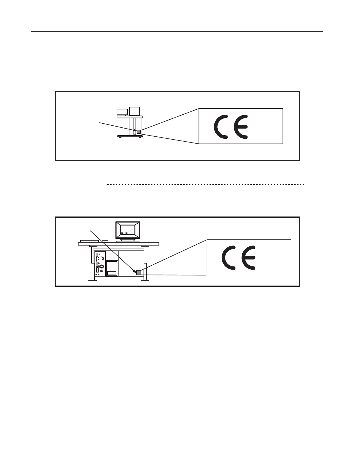
1-3
CE MARKING LABEL
This CT system is either an EMC model, or non–EMC model. (EMC: Electromagnetic Compatibility)
For
the EMC
models, a ‘CE Marking Label’ is attached on the rear side of the Operator Console, near its rating plate.
CE MARKING
LABEL
0459
OC
REAR
VIEW
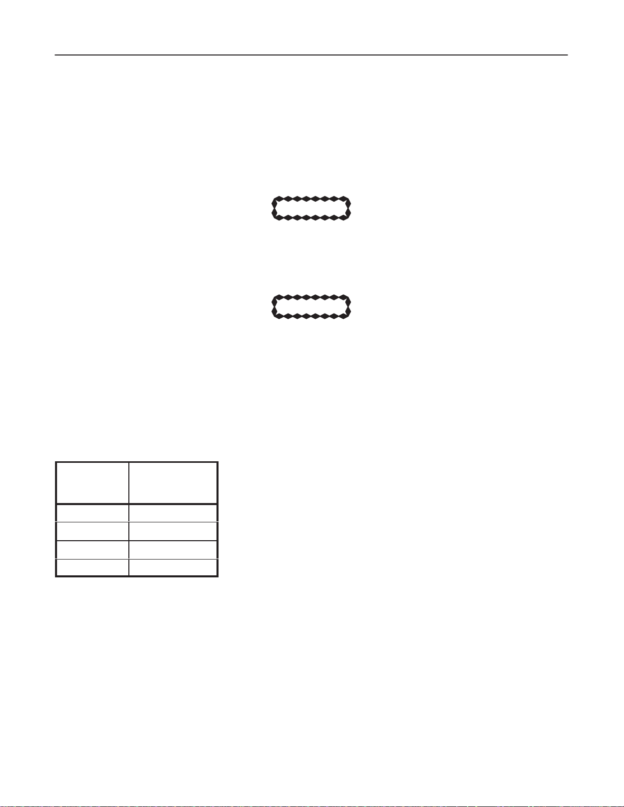
1-4
CE MARKING LABEL
This CT system is either an EMC model, or non–EMC model. (EMC: Electromagnetic Compatibility)
For
the EMC
models, a ‘CE Marking Label’ is attached on the rear side of the Operator Console, near its rating plate.
2208844
(LGT
, SRI)
(SNG)
CE MARKING
LABEL
OC REAR VIEW
0459
INTRODUCTION1–6
Page 21
GE MEDICAL
SYSTEMS
FUNCTIONAL
CT XMj/XM1500 SERIES
CHECK /
ADJUSTMET
REV 0
2208844
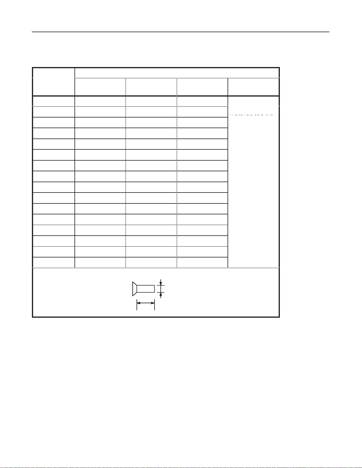
SECTION 2 – TORQUE VALUE FOR SCREW TIGHTENING
CAUTION
Use locktite for screws which are installed to the Gantry rotation block. Use stud bolt with
locktite
When you secure stud bolts with locktite, you must keep the screw torque shown in Table
‘Stud Bolt (Steel) with Locktite.’
Do
100
or nylon nut to prevent loosening if a screw is removed in service maintenance.
CAUTION
not rotate the Gantry until the locktite hardens.
% after 16 hours.)
(75 % of maximum strength after 2 hours;
If it is not possible to wait for the time period mentioned above, use nylon nuts.
T
ABLE 2–1
Screw Size
M 4
M 5
M 6
M 8
*Unless otherwise specified
UNIT
Kg–cm
Stud Bolt (Steel) with Locktite
Torque [kg–cm]
(Unless other
wise specified)
10
15
35
70
-
INTRODUCTION2–1
Page 22
GE MEDICAL
material, use the
SYSTEMS
FUNCTIONAL
CT XMj/XM1500 SERIES
CHECK /
ADJUSTMET
REV 0
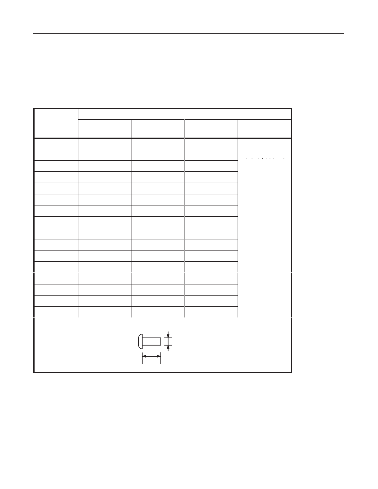
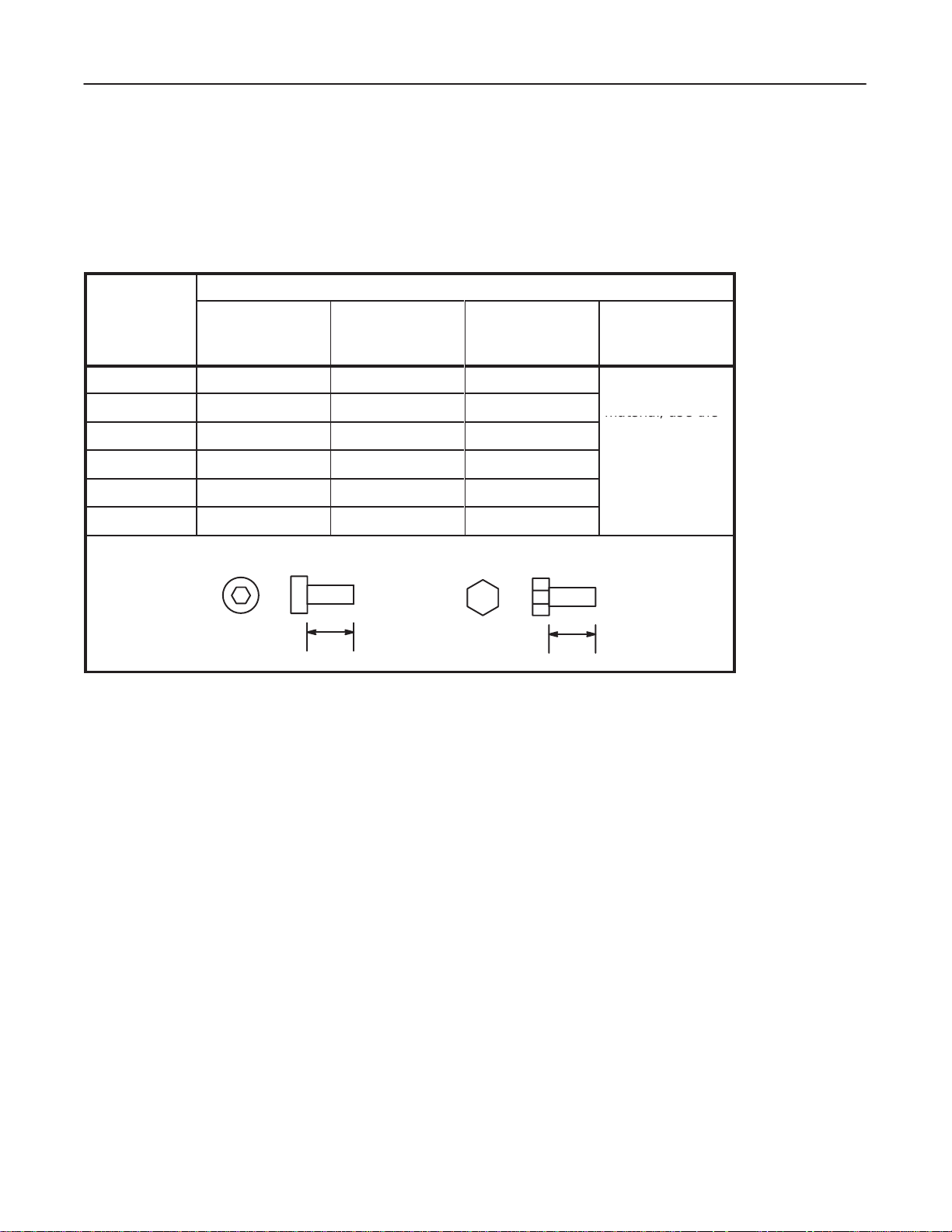
2-1
NORMAL SCREWS
Secure normal screws with the tightening torque shown in the following tables
T
ABLE 2–2
Screw Size
M 1
M 1.2
M 1.4
M 1.7
M 2
M 2.2
M 2.3
Pan Head Screw
T
orque [kg–cm] (Unless otherwise specified)
Brass
(Screw & Nut)
Steel (4.8)
(Screw & Nut)
0.17 0.18 0.22
0.32 0.34 0.42
0.49 0.52 0.65
0.90 0.96 1.2
1.5 1.6 1.9
1.9 2.0 2.5
2.3 2.5 3.1
Stainless
(Screw & Nut)
If screw and nut
are of dif
material, use the
weakest torque.
unless otherwise specified
(Combination)
ferent
2208844
.
M 2.5
M 2.6
M 3
M 3.5
3.0 3.2 4.0
3.4 3.6 4.5
5.3 5.7 7.1
8.2 8.7 11
M 4
M 4.5
M 5
M 6
M 8
*Unless otherwise specified
UNIT
Kg–cm
17.5 19 23.5
24.5 26.5 33
41.5 44 55
101 108 135
12 13 16
Style
M
L
INTRODUCTION2–2
Page 23
GE MEDICAL
material, use the
SYSTEMS
FUNCTIONAL
CT XMj/XM1500 SERIES
CHECK /
ADJUSTMET
REV 0
Screw Size
M 1
M 1.2
M 1.4
M 1.7
M 2
M 2.2
M 2.3
M 2.5
M 2.6
M 3
M 3.5
T
ABLE 2–3
Binder Screw
T
orque [kg–cm] (Unless otherwise specified)
Brass
(Screw & Nut)
Steel (4.8)
(Screw & Nut)
– – –
– – –
– – –
– – –
1.6 1.7 2.1
2.0 2.2 2.7
2.5 2.7 3.4
3.2 3.4 4.2
3.6 3.9 4.8
5.6 6.0 7.5
8.7 9.3 11.5
Stainless
(Screw & Nut)
(Combination)
If screw and nut
are of dif
ferent
material, use the
weakest torque.
2208844
M 4
M 4.5
18.5 20 25
M 5
M 6
M 8
*Unless otherwise specified
UNIT
Kg–cm
107 114 143
13 13.5 17
26 27.5 34.5
44 47 58.5
Style
M
L
INTRODUCTION2–3
Page 24
GE MEDICAL
material, use the
SYSTEMS
FUNCTIONAL
CT XMj/XM1500 SERIES
CHECK /
ADJUSTMET
REV 0
Screw Size
M 1
M 1.2
M 1.4
M 1.7
M 2
M 2.2
M 2.3
M 2.5
M 2.6
M 3
M 3.5
T
ABLE 2–4
Flat Head Screw
T
orque [kg–cm] (Unless otherwise specified)
Brass
(Screw & Nut)
Steel (4.8)
(Screw & Nut)
0.21 0.22 0.27
0.39 0.42 0.52
0.61 0.65 0.82
1.1 1.2 1.5
1.9 2.0 2.5
2.4 2.6 3.2
3.0 3.2 4.0
3.8 4.1 5.1
4.4 4.6 5.8
6.8 7.2 9.0
10.5 11 14
Stainless
(Screw & Nut)
(Combination)
If screw and nut
are of dif
ferent
material, use the
weakest torque.
2208844
M 4
M 4.5
M 5
15.5 16.5 20.5
22.5 24 30
31.5 33.5 42
M 6
M 8
*Unless otherwise specified
UNIT
Kg–cm
130 139 173
53 56.5 71
Style
M
L
INTRODUCTION2–4
Page 25
GE MEDICAL
material, use the
SYSTEMS
FUNCTIONAL
CT XMj/XM1500 SERIES
CHECK /
ADJUSTMET
REV 0
2-2
HEXAGON SCREWS
T
ighten allen (hexagonal) screws with the torque shown in T
T
ABLE 2–5
Screw Size
M 4
M 5
M 6
M 8
M 10
M 12
Hexagon Screw
T
orque [kg–cm] (Unless otherwise specified)
Ferrite
(Screw & Nut)
Aluminum
(Screw & Nut)
35 28 17.5
70 56 35
117 96.3 58.5
285 228 142.5
563 450.4 281.5
976 780.8 488
able below
unless otherwise specified
Aluminum Steel
Alloy
(Screw & Nut)
(Combination)
If screw and nut
are of dif
ferent
material, use the
weakest torque.
2208844
.
Style
*Unless otherwise specified
UNIT
Kg–cm
or
L
L
INTRODUCTION2–5
Page 26

GE MEDICAL
SYSTEMS
FUNCTIONAL
CT XMj/XM1500 SERIES
CHECK /
ADJUSTMET
blank
2208844
INTRODUCTION2–6
Page 27

GE MEDICAL
SYSTEMS
FUNCTIONAL
CT XMj/XM1500 SERIES
CHECK /
ADJUSTMENT
REV 0
SYSTEM
TABLE OF CONTENTS
SECTION PAGE
SECTION
1 – CHECKS DURING SYSTEM INST
1 GROUND CONTINUITY 1–1.
2 LOAD DISTRIBUTION 1–1.
2–1 PDU:2108024/2108025 (LGT, SRI) 1–2.
2–2 PDU:2108024/2108025 (SNG) 1–9.
2–3 2121798 PDU (LGT, SRI) 1–11.
2–4 2121798 PDU (SNG) 1–14.
3 GANTRY ROTATION CHECK 1–17.
4 EMERGENCY OFF TEST 1–18.
5 X–RAY TUBE OVERHEAT SAFETY 1–22.
6 X–RAY TUBE OIL 1–24.
7 FANS 1–26
8 FILTER 1–27
9 SCAN TEST (LGT, SRI) 1–28.
10 SCAN TEST (SNG) 1–31.
. . . . . . . . . . . . . . . . . . . . . . . . . . . . . . . . . . . . . . . . . . . . . . . . . . . . . . . . . . . . . . . . . . .
. . . . . . . . . . . . . . . . . . . . . . . . . . . . . . . . . . . . . . . . . . . . . . . . . . . . . . . . . . . . . . . . .
. . . . . . . . . . . . . . . . . . . . . . . . . . . . . . . . . . . . . . . . . . . . . . . . . .
. . . . . . . . . . . . . . . . . . . . . . . . . . . . . . . . . . . . . . . . . . . . . . . . . . .
. . . . . . . . . . . . . . . . . . . . . . . . . . . . . . . . . . . . . . . . . . . . . . . .
. . . . . . . . . . . . . . . . . . . . . . . . . . . . . . . . . . . . . . . . . . . . . . . . . . . . . . .
. . . . . . . . . . . . . . . . . . . . . . . . . . . . . . . . . . . . . . . . . . . . . . . . . .
. . . . . . . . . . . . . . . . . . . . . . . . . . . . . . . . . . . . . . . . . . . . . . . . . . . . . .
ALLATION 1–1.
. . . . . . . . . . . . . . . . . . . . . . . . . . . . . . . . . . . .
. . . . . . . . . . . . . . . . . . . . . . . . . . . . . . . . . . . . . . . . .
. . . . . . . . . . . . . . . . . . . . . . . . . . . . . . . . . . . . . . . . . . . . .
. . . . . . . . . . . . . . . . . . . . . . . . . . . . . . . . . . . . . . . . . . . . .
. . . . . . . . . . . . . . . . . . . . . . . . . . . . . . . . . . . . . . . .
. . . . . . . . . . . . . . . . . . . . . . . . .
. . . . . . . . . . . . . . . . . . . . . . . . . . . . . . . . .
2208844
SECTION
SECTION
SECTION
2 – SOFTW
1 GENERAL 2–1.
2 FLOPPY DISKS FOR SYSTEM/OPTION SOFTWARE 2–3.
3 PRE–ATINST PROCEDURE 2–5.
4 SOFTWARE LOADING (ATINST) 2–15.
5 POST–ATINST PROCEDURE 2–21.
3 – SOFTW
1 GENERAL 3–1.
2 FLOPPY DISKS FOR SYSTEM/OPTION SOFTWARE 3–3.
3 PRE–ATINST PROCEDURE 3–5.
4 SOFTWARE LOADING (ATINST) 3–15.
5 POST–ATINST PROCEDURE 3–21.
4 – SOFTW
1 GENERAL 4–1.
2 SOFTWARE LOADING 4–2.
ARE LOADING (V2.02)
. . . . . . . . . . . . . . . . . . . . . . . . . . . . . . . . . . . . . . . . . . . . . . . . . . . . . . . . . . . . . .
. . . . . . . . . . . . . . . . . . . . . . . . . . . . . . . . . . . . . . . . . . . . . .
. . . . . . . . . . . . . . . . . . . . . . . . . . . . . . . . . . . . . . . . . .
. . . . . . . . . . . . . . . . . . . . . . . . . . . . . . . . . . . . . . . . . . . . .
ARE LOADING (V3.00)
. . . . . . . . . . . . . . . . . . . . . . . . . . . . . . . . . . . . . . . . . . . . . . . . . . . . . . . . . . . . . .
. . . . . . . . . . . . . . . . . . . . . . . . . . . . . . . . . . . . . . . . . . . . . .
. . . . . . . . . . . . . . . . . . . . . . . . . . . . . . . . . . . . . . . . . .
. . . . . . . . . . . . . . . . . . . . . . . . . . . . . . . . . . . . . . . . . . . . .
ARE LOADING (V3.01)
. . . . . . . . . . . . . . . . . . . . . . . . . . . . . . . . . . . . . . . . . . . . . . . . . . . . . . . . . . . . . .
. . . . . . . . . . . . . . . . . . . . . . . . . . . . . . . . . . . . . . . . . . . . . . . . . . .
(LGT
, SRI)
. . . . . . . . . . . . . . . . . . . . . . . .
(LGT
, SRI)
. . . . . . . . . . . . . . . . . . . . . . . .
(LGT
, SRI)
2–1
3–1
4–1
SYSTEMi
Page 28

GE MEDICAL
REV
0
SECTION PAGE
SYSTEMS
TABLE OF CONTENTS
FUNCTIONAL
CT XMj/XM1500 SERIES
CHECK /
ADJUSTMENT
2208844
SECTION
SECTION
SECTION
SECTION
5 – SOFTW
1 GENERAL 5–1.
2 DATA SAVE 5–2.
3 HARDWARE SETTING 5–5.
4 SOFTWARE LOADING 5–7.
5 DATA RESTORE 5–20.
6 – X–RA
1 GENERAL 6–1.
2 PLANE OF ROTATION 6–5.
3 DETECTOR BEAM–ON–WINDOW 6–11.
4 GRAVITY SAG 6–17.
5 ISO CENTER ALIGNMENT 6–24.
6 FILTER CENTER ALIGNMENT 6–30.
7 – SYSTEM CALIBRA
1 GENERAL 7–1.
2 CAM AMPLIFIER LINEARITY CHECK (X–RAYS) (LGT, SRI) 7–3
3 AIR AND PHANTOM CALIBRATIONS (LGT, SRI) 7–7
4 CT NUMBER ADJUSTMENT (LGT, SRI) 7–9
5 CAL + AUTO CT NUMBER ADJUSTMENT (SNG) 7–13
6 AUTO CT NUMBER ADJUSTMENT (SNG) 7–16
8 – IMAGE PERFORMANCE VERIFICA
1 IMAGE PERFORMANCE (LGT, SRI) 8–1
2 IMAGE PERFORMANCE (SNG) 8–9
ARE LOADING (SNG) 5–1
. . . . . . . . . . . . . . . . . . . . . . . . . . . . . . . . . . . . . . . . . . . . . . . . . . . . . . . . . . . . . .
. . . . . . . . . . . . . . . . . . . . . . . . . . . . . . . . . . . . . . . . . . . . . . . . . . . . . . . . . . . . .
. . . . . . . . . . . . . . . . . . . . . . . . . . . . . . . . . . . . . . . . . . . . . . . . . . .
. . . . . . . . . . . . . . . . . . . . . . . . . . . . . . . . . . . . . . . . . . . . . . . . . . .
. . . . . . . . . . . . . . . . . . . . . . . . . . . . . . . . . . . . . . . . . . . . . . . . . . . . . . . .
Y ALIGNMENT
. . . . . . . . . . . . . . . . . . . . . . . . . . . . . . . . . . . . . . . . . . . . . . . . . . . . . . . . . . . . . .
. . . . . . . . . . . . . . . . . . . . . . . . . . . . . . . . . . . . . . . . . . . . . . . . . . . . . . . . . . . . . .
. . . . . . . . . . . . . . . . . . . . . . . . . . . . . . . . . . . . . . . . . . . . . . .
. . . . . . . . . . . . . . . . . . . . . . . . . . . . . . . . . . . . . . . . . . . . . . . . . . .
. . . . . . . . . . . . . . . . . . . . . . . . . . . . . . . . . . . . . . . .
. . . . . . . . . . . . . . . . . . . . . . . . . . . . . . . . . . . . . . . . . . . . . . . . . . . . . . . . . .
. . . . . . . . . . . . . . . . . . . . . . . . . . . . . . . . . . . . . . . . . . . . . . .
. . . . . . . . . . . . . . . . . . . . . . . . . . . . . . . . . . . . . . . . . . . .
TION 7–1.
. . . . . . . . . . . . . . . . . . . . . . . . . . . . . . . . . . . . . . . . . . .
TION 8–1.
. . . . . . . . . . . . . . . . . . . . . . . . . . . .
6–1.
SECTION
9 – NETWORK
1 GENERAL (SNG) 9–1
2 COMMUNICATION DATA HANDLING (SNG) 9–1
. . . . . . . . . . . . . . . . . . . . . . . . . . . . . . . . . . . . . . . . . . . . . . . . . . . . . . .
9–1.
SYSTEMii
Page 29
GE MEDICAL
SYSTEMS
FUNCTIONAL
CT XMj/XM1500 SERIES
CHECK /
ADJUSTMENT
REV 0
SECTION 1 – CHECKS DURING SYSTEM INSTALLATION
1. GROUND
Refer
to Section 4, Ground Continuity Check, of the Installation tab of the Installation/Component Replacement manu
al
(2111461 or 2121807).
2. LOAD DISTRIBUTION
ELECTROCUTION! DANGEROUS VOLTAGES EXIST WITHIN THE UNITS, USE EXTREME
CARE TO A
CONTINUITY
VOID INJUR
WARNING!
Y T
O PERSONNEL AND EQUIPMENT
.
2208844
-
CAUTION
Leave all power to the system OFF and tagged until power is called for in specific steps.
Follow the steps below
Follow this sequence to protect you and the equipment from irreparable damage.
PDU Model
Select a correct PDU model from the menu which your system includes.
exactly
in the order they are written. This procedure is developed with your safety in mind.
SYSTEM1–1
Page 30

GE MEDICAL
SYSTEMS
FUNCTIONAL
CT XMj/XM1500 SERIES
CHECK /
ADJUSTMENT
REV 0
2–1.
PDU:2108024/2108025
1. Preparation.
a. V
erify that all the breakers and switches listed below are set to OFF
Breaker on the Power Distribution Box (hospital supply).
Breaker (SW20) on the PDU
Five switches (‘Rotate,’ ‘XG,’ ‘T
Servo Amp. breaker
Service switch on the Sub Board on the Gantry
SYS/OFF/MNL switch on the TGP Board on the Gantry
T
wo breakers (NFB1, NFB2) on the OC See Illustration.2.
b.
Remove the front panel from the PDU.
c.
Remove the top cover from the OC.
able/T
ilt,’ ‘Control,’ and ’Slip Ring 1
.
15V’) at the Gantry rear base
2208844
(LGT
, SRI)
d.
Remove the left side cover from the Gantry
2.
Switch ON two breakers (NFB1, NFB2) on the OC.
3.
Switch ON the breaker on the Power Distribution Box (hospital supply).
4.
Switch ON the SW20 breaker on the PDU.
V
erify that the ‘Power
’ lamp on the front upper left corner of the PDU turns ON.
.
SYSTEM1–2
Page 31

GE MEDICAL
SYSTEMS
FUNCTIONAL
CT XMj/XM1500 SERIES
CHECK /
ADJUSTMENT
REV 0
5.
Measure 1
It should be
6.
Switch ON the ‘Slip Ring 1
Verify
15 V
AC between terminals 15 and 16 on TB37 on the PDU.
103.5 ~ 126.5 VAC. See Illustration.1.
15V (DAS/DET)’ switch at the Gantry rear base.
that the x–ray generator on the rotating assembly is powered ON, and that the x–ray tube fan and pump
start to operate.
7.
Push the ‘Power
V
erify that the voltage between terminals 1
8.
Measure
9. V
erify that the Servo Amp. breaker is set to OFF
10.
Switch ON the ‘Rotate’ switch at the Gantry rear base.
103.5 ~ 126.5 VAC between terminals 10 and 1
’ switch on the OC.
1 and 12 on TM 1 of the OC is
1 on TB37 on the PDU. See Illustration.5.
.
Measure 180 ~ 220 VAC on the Servo Amp. input (between terminals R & S, S & T
23
22
19
18
90 ~ 1
10 VAC. See Illustration.2.
, and T & R). See Illustration.6.
2208844
PDU TB37 TERMINALS NO. 15, 16
ILLUSTRATION 1
21
21
20
20
17
16
15
14
7
6
5
4
BROWN
LIGHT
BLUE
NO.
4
CABLE
SYSTEM1–3
Page 32

GE MEDICAL
REV
0
SYSTEMS
NFB2
NFB1
CT XMj/XM1500 SERIES
FUNCTIONAL
CHECK /
ADJUSTMENT
2208844
REMOVE THE OC
T
OP COVER
11112
TM1
PS DISTR ASSY
PS ADP ASSY
(TOP VIEW)
OPERATOR CONSOLE
ILLUSTRATION 2
SYSTEM1–4
Page 33

GE MEDICAL
REV
0
SYSTEMS
OC LEFT SIDE METAL COVER
FUNCTIONAL
REMOVE THE RIGHT METAL COVER
CT XMj/XM1500 SERIES
CHECK /
ADJUSTMENT
2208844
OC
POWER
P
ANEL T
OP COVER
CB1
OPERATOR CONSOLE
ILLUSTRATION 3
SYSTEM1–5
Page 34

GE MEDICAL
REV
0
REAR VIEW
SYSTEMS
CB1
OC Power Panel
FUNCTIONAL
CT XMj/XM1500 SERIES
CHECK /
ADJUSTMENT
2208844
TB1
Filter
OC POWER PANEL
ILLUSTRATION 4
SYSTEM1–6
Page 35

GE MEDICAL
ÁÁÁÁ
ÁÁÁÁ
REV
0
SYSTEMS
FUNCTIONAL
7
6
5
4
21
21
20
20
17
16
15
14
13
12
11
10
9
8
7
6
5
4
BROWN
LIGHT BLUE
BROWN
LIGHT BLUE
BLACK
WHITE
RED
LIGHT BLUE
CT XMj/XM1500 SERIES
CHECK /
ADJUSTMENT
2208844
NO.4 CABLE
NO.
3
CABLE
NO.2 CABLE
NO.5 CABLE
100V AC
PDU TB37 TERMINALS NO. 10, 11
ILLUSTRATION 5
SYSTEM1–7
Page 36

GE MEDICAL
REV
0
SYSTEMS
front
view
left view
SER
VO AMP
SUB
board
1 byte segment led
TGP
BOARD
CT XMj/XM1500 SERIES
FUNCTIONAL
.
CHECK /
ADJUSTMENT
2208844
SERVO AMP.
CONNECTOR
SERVO AMP. TERMINALS R, S, T
RST
ILLUSTRATION 6
SYSTEM1–8
Page 37

GE MEDICAL
REV
0
2–2.
PDU: 2108024/2108025
1. Preparation.
a. V
SYSTEMS
erify that all the breakers and switches listed below are set to OFF
Breaker on the Power Distribution Box (hospital supply).
Breaker (SW20) on the PDU
FUNCTIONAL
.
CT XMj/XM1500 SERIES
CHECK /
ADJUSTMENT
2208844
(SNG)
Five switches (‘Rotate,’ ‘XG,’ ‘T
Servo Amp. breaker
Service switch on the Sub Board on the Gantry
SYS/OFF/MNL switch on the TGP Board on the Gantry
Power Panel Breaker CB1 on the OC See Illustration.3.
Remove the front panel from the PDU.
Remove the OC Power Panel T
Remove the left side cover from the Gantry
b.
Switch ON Power Panel Breaker CB1 on the OC.
c.
Switch ON the breaker on the Power Distribution Box (hospital supply).
d.
Switch ON the SW20 breaker on the PDU.
V
erify that the ‘Power
’ lamp on the front upper left corner of the PDU turns ON.
able/T
op cover.
ilt,’ ‘Control,’ and ’Slip Ring 1
.
15V’) at the Gantry rear base
SYSTEM1–9
Page 38

GE MEDICAL
SYSTEMS
FUNCTIONAL
CT XMj/XM1500 SERIES
CHECK /
ADJUSTMENT
REV 0
5.
Measure 1
It should be
6.
Switch ON the ‘Slip Ring 1
Verify
start to operate.
7. T
urn on the CONSOLE Power by depressing the Scan T
8.
Open the OC power panel cover to access the Power strip.
See Illustration.4.
9.
Measure the power at the OC Console Power Strip. V
See Illustration.4.
10.
Measure
11. V
erify that the Servo Amp. breaker is set to OFF
12.
Switch ON the ‘Rotate’ switch at the Gantry rear base.
Measure 180 ~ 220 VAC on the Servo Amp. input (between terminals R & S, S & T
15 V
AC between terminals 15 and 16 on TB37 on the PDU.
103.5 ~ 126.5 VAC. See Illustration.1.
15V (DAS/DET)’ switch at the Gantry rear base.
that the x–ray generator on the rotating assembly is powered ON, and that the x–ray tube fan and pump
ower Power Switch.
103.5
~
126.5 VAC between terminals 10 and 1
.
erify there is
1 on TB37 on the PDU. See Illustration.5.
108 ~ 122 VAC at the Power strip.
2208844
, and T & R). See Illustration.6.
SYSTEM1–10
Page 39

GE MEDICAL
REV
0
2–3.
PDU: 2121798
1. Preparation.
a. V
SYSTEMS
erify that all the breakers and switches listed below are set to OFF
Breaker on the Power Distribution Box (hospital supply).
Breaker (CB20) on the PDU
FUNCTIONAL
.
CT XMj/XM1500 SERIES
CHECK /
ADJUSTMENT
2208844
(LGT
, SRI)
Five switches (‘Rotate,’ ‘XG,’ ‘T
Servo Amp. breaker
Service switch on the Sub Board on the Gantry
SYS/OFF/MNL switch on the TGP Board on the Gantry
T
wo breakers (NFB1, NFB2) on the OC See Illustration.2.
b.
Remove the front panel from the PDU.
c.
Remove the top cover from the OC.
d.
Remove the left side cover from the Gantry
2.
Switch ON two breakers (NFB1, NFB2) on the OC.
3.
Switch ON the breaker on the Power Distribution Box (hospital supply).
4.
Switch ON the CB20 breaker on the PDU.
V
erify the ‘Power
’ lamp on the front upper left corner of the PDU turns ON.
able/T
ilt,’ ‘Control,’ and ’Slip Ring 1
.
15V’) at the Gantry rear base
SYSTEM1–11
Page 40

GE MEDICAL
SYSTEMS
FUNCTIONAL
CT XMj/XM1500 SERIES
CHECK /
ADJUSTMENT
REV 0
5.
Measure 1
It should be
6.
Switch ON the ‘Slip Ring 1
Verify
15 V
AC between terminals 8 and 9 on the PDU.
103.5 ~ 126.5 VAC. See Illustration.7.
15V (DAS/DET)’ switch at the Gantry rear base.
that the x–ray generator on the rotating assembly is powered ON, and that the x–ray tube fan and pump
start to operate.
7.
Push the ‘Power
V
erify that the voltage between terminals 1
8.
Measure
9. V
erify that the Servo Amp. breaker is set to OFF
10.
Switch ON the ‘Rotate’ switch at the Gantry rear base.
103.5 ~ 126.5 VAC between terminals 1
’ switch on the OC.
1 and 12 on TM 1 of the OC is
1 and 12 on the PDU. See Illustration.8.
.
Measure 180 ~ 220 VAC on the Servo Amp. input (between terminals R & S, S & T
90 ~ 1
10 VAC. See Illustration.2.
, and T & R). See Illustration.6.
2208844
171617
RED
NO.2 CABLE
NO.3 CABLE
NO.
4
CABLE
NO.21 CABLE
L3
L2
L1
PDU TERMINALS NO. 8, 9
YELLOW/GREEN
ILLUSTRATION 7
WHITE
BLACK
BROWN
LIGHT BLUE
BROWN
LIGHT
BLUE
15
14
13
12
11
10
989
7
16
15
14
13
12
11
10
ROTATE
PWR
TABLE/TILT
&
CONTROL
PWR
SLIP RING
1
8
7
15V PWR
GND
SYSTEM1–12
Page 41

GE MEDICAL
REV
0
SYSTEMS
CT XMj/XM1500 SERIES
FUNCTIONAL
CHECK /
ADJUSTMENT
2208844
171617
RED
NO.2 CABLE
NO.
3
CABLE
NO.4 CABLE
NO.21 CABLE
L3
L2
L1
YELLOW/GREEN
WHITE
BLACK
BROWN
LIGHT
BLUE
BROWN
LIGHT BLUE
15
14
13
12
11
10
989
7
16
15
14
13
12
11
10
ROTATE
PWR
TABLE/TILT
CONTROL
PWR
&
SLIP RING
1
8
7
15V PWR
GND
PDU TERMINALS NO. 11, 12
ILLUSTRATION 8
SYSTEM1–13
Page 42

GE MEDICAL
REV
0
2–4.
PDU: 2121798
1. Preparation.
a. V
SYSTEMS
erify that all the breakers and switches listed below are set to OFF
Breaker on the Power Distribution Box (hospital supply).
Breaker (CB20) on the PDU
FUNCTIONAL
.
CT XMj/XM1500 SERIES
CHECK /
ADJUSTMENT
2208844
(SNG)
Five switches (‘Rotate,’ ‘XG,’ ‘T
Servo Amp. breaker
Service switch on the Sub Board on the Gantry
SYS/OFF/MNL switch on the TGP Board on the Gantry
Power Panel Breaker CB1 on the OC See Illustration.3.
b.
Remove the front panel from the PDU.
c.
Remove the OC Power Panel T
d.
Remove the left side cover from the Gantry
2.
Switch ON Power Panel Breaker CB1 on the OC.
3.
Switch ON the breaker on the Power Distribution Box (hospital supply).
4.
Switch ON the CB20 breaker on the PDU.
V
erify the ‘Power
’ lamp on the front upper left corner of the PDU turns ON.
able/T
ilt,’ ‘Control,’ and ’Slip Ring 1
op cover.
.
15V’) at the Gantry rear base
SYSTEM1–14
Page 43

GE MEDICAL
SYSTEMS
FUNCTIONAL
CT XMj/XM1500 SERIES
CHECK /
ADJUSTMENT
REV 0
5.
Measure 1
It should be
6.
Switch ON the ‘Slip Ring 1
Verify
start to operate.
7. T
urn on the CONSOLE Power by depressing the Scan T
8.
Open the OC power panel cover to access the Power strip.
See Illustration.4.
9.
Measure the power at the OC Console Power Strip. V
See Illustration.4.
10.
Measure
11. V
erify that the Servo Amp. breaker is set to OFF
12.
Switch ON the ‘Rotate’ switch at the Gantry rear base.
Measure 180
15 V
AC between terminals 8 and 9 on the PDU.
103.5
~
126.5 VAC. See Illustration.7.
15V (DAS/DET)’ switch at the Gantry rear base.
that the x–ray generator on the rotating assembly is powered ON, and that the x–ray tube fan and pump
103.5
~
126.5 VAC between terminals 1
~
220 VAC on the Servo Amp. input (between terminals R & S, S & T
ower Power Switch.
erify there is
1 and 12 on the PDU. See Illustration.8.
.
108
~
122 VAC at the Power strip.
, and T & R). See Illustration.6.
2208844
SYSTEM1–15
Page 44

GE MEDICAL
SYSTEMS
FUNCTIONAL
CT XMj/XM1500 SERIES
CHECK /
ADJUSTMENT
blank
2208844
SYSTEM1–16
Page 45

GE MEDICAL
SYSTEMS
FUNCTIONAL
CT XMj/XM1500 SERIES
CHECK /
ADJUSTMENT
REV 0
3. GANTR
Y ROTATION CHECK
WARNING!
ROTATION
ARE HAZARDS INVOLVED IN WORKING ON OR NEAR THE GANTRY. THE MOST OBVIOUS
HAZARD IS THE AXIAL MOTION OF THE GANTRY. THE HIGH VOLTAGE (HV) SUBSYSTEM
IS MOUNTED DIRECTLY ONTO THE GANTRY. THE HV SUBSYSTEM CONSISTS OF
COMPONENTS THA
1.
Switch OFF the ‘Rotate’ switch.
2.
Remove the front and both side covers from the Gantry
3.
Set the safety bracket located on the right side of the Gantry
4.
Switch ON the ‘Control’ and ‘T
HAZARD! BECAUSE OF THE CONTINUOUS ROTATION OF
T ARE BULKY AND HEAVY. GIVE ROTATION HAZARDS RESPECT
able/T
ilt’ switches at the Gantry rear base.
2208844
THE GANTR
.
.
Y THERE
.
5.
Set the Service switch to ON on the SUB Board on the Gantry
6. Rotate
7. Set
8.
9.
10.
11.
10.
11.
12. Verify
the Gantry manually in
etc.).
the Service switch to OFF
Switch ON the ‘Rotate’ switch.
Switch ON the Servo Amp. breaker
Switch OFF the ‘Power’ switch on the OC.
Switch ON the ‘Power
Push OFF “Power” switch on the Scan T
Push ON the “Power” switch on the Scan T
that the Gantry starts to
making
two revolutions.
’ switch on the OC.
the CW direction to verify that nothing interferes the Gantry during rotation (cables,
.
.
ower.
rotate, and it stops at the home position (x–ray tube at 12 o’clock position) before
ower.
.
(LGT
, SRI)
(SNG)
(LGT
, SRI, SNG)
SYSTEM1–17
Page 46

GE MEDICAL
SYSTEMS
FUNCTIONAL
CT XMj/XM1500 SERIES
CHECK /
ADJUSTMENT
REV 0
4.
EMERGENCY OFF TEST
Eight
emergency switches in total are equipped on the system.
Illustration.9.
EMERGENCY SWITCH
ILLUSTRATION 9
1.
Remove the Gantry left side cover
2.
Press the emergency switch located on the front of the PDU.
V
erify that power is removed from the Gantry and T
. (The other covers should be installed)
The switches take either one of the two shapes. See
RED
COLOR
able; check the following:
2208844
(LGT,
SRI)
One byte segment LED on the Servo Amp. is extinguished. See Illustration.10.
Gantry Display Panels (right and left) are extinguished.
3.
Press the power switch on the OC
V
erify that power is applied to the Gantry and T
One byte segment LED on the Servo Amp. is illuminated. See Illustration.10.
Gantry Display Panels (right and left) are illuminated.
twice.
able; check the following:
SYSTEM1–18
Page 47

GE MEDICAL
SYSTEMS
FUNCTIONAL
CT XMj/XM1500 SERIES
CHECK /
ADJUSTMENT
REV 0
4.
Repeat the above check for emergency switches located on the followings:
Operator Console (one)
Gantry front cover (two; right and left)
1.
Remove the Gantry left side cover
2.
Press the emergency switch located on the front of the PDU.
V
erify that power is removed from the Gantry and T
One byte segment LED on the Servo Amp. is extinguished. See Illustration.10.
Gantry Display Panels (right and left) are extinguished.
3.
Power down the W
4. T
urning of
5.
Push (of
6.
Push (on) Scan T
V
erify that power is applied to the Gantry and T
f the W
f) Scan T
orkstation by exiting from the application software.
orkstation power switch
ower Power Switch.
ower Power Switch.
. (The other covers should be installed)
able; check the following:
.
able; check the following:
2208844
(SNG)
One byte segment LED on the Servo Amp. is illuminated. See Illustration.10.
Gantry Display Panels (right and left) are illuminated.
7.
Repeat the above check for emergency switches located on the followings:
Operator Console Scan Box (one)
Gantry front cover (two; right and left)
SYSTEM1–19
Page 48

GE MEDICAL
SYSTEMS
FUNCTIONAL
CT XMj/XM1500 SERIES
CHECK /
ADJUSTMENT
REV 0
Emergency Switches on Gantry Frame
1.
Remove the front, rear
2.
Connect the emergency cable, as shown in Illustration.1
3. Repeat
‘D’
4. Repeat
and
1.
Remove the front, rear
2.
Connect the emergency cable, as shown in Illustration.1
3. Repeat
‘D’
4. Repeat
and
the emergency switch check as performed in steps 2 and 3 for the emergency switches ‘A
located on the Gantry frame. See Illustration.12.
the emergency switch
‘D’ located on the Gantry frame. See Illustration.12.
the emergency switch check as performed in steps 2 and 3 for the emergency switches ‘A
located on the Gantry frame. See Illustration.12.
the emergency switch
‘D’ located on the Gantry frame. See Illustration.12.
, and right side covers from the Gantry
check as performed in steps 2 and 3 6 for the emergency switches ‘A
, and right side covers from the Gantry
check as performed in steps 2 and 3 6 for the emergency switches ‘A
1.
1.
2208844
(LGT
, SRI)
.
’, ‘B’, ‘C’,
.
’, ‘B’, ‘C’,
and
’, ‘B’, ‘C’,
(SNG)
and
’, ‘B’, ‘C’,
front view
1 byte segment led
servo amp.
sub
board
TGP
BOARD
LED ON SERVO AMP
ILLUSTRATION 10
gantry
front
SYSTEM1–20
Page 49

GE MEDICAL
REV
0
SYSTEMS
EMERGENCY SW
X–RAY
TUBE
GANTRY
CT XMj/XM1500 SERIES
FUNCTIONAL
CHECK /
FRONT COVER
REVERSE
SIDE
ADJUSTMENT
2208844
CONNECTOR
EMERGENCY
SW ‘A’
EMERGENCY
SW ‘B’
STEP 2:
CONNECT
STEP 1:
DISCONNECT THE 2–PIN
WHITE/BLACK
CONNECTORS
TWIST CABLE
EMERGENCY SW CABLE CONNECTION
ILLUSTRATION 11
X–RAY
TUBE
EMERGENCY
SW ‘D’
EMERGENCY
SW ‘C’
GANTRY FRONT VIEW
EMERGENCY SWITCH LOCATIONS
ILLUSTRATION 12
GANTRY REAR VIEW
SYSTEM1–21
Page 50

GE MEDICAL
REV
0
SYSTEMS
FUNCTIONAL
CT XMj/XM1500 SERIES
CHECK /
ADJUSTMENT
2208844
5 X–RA
Check for the overheat detection function by performing the following:
1.
2.
3.
4.
5. T
Y TUBE OVERHEA
Switch OFF the ‘Rotate’ switch.
Remove the front and both side covers from the Gantry
Disconnect the rotor cable connector (12–pin, brown). See Illustration.13.
If the connector is not accessible, perform the following.
a.
Set the Service switch to ON on the SUB Board.
b.
Rotate the Gantry manually in the CW direction to a position where the connector can be accessed.
c.
Set the Service switch to OFF
Switch ON the ‘Rotate’ switch.
ry to perform a scan.
Verify
that a scan can not be performed and that the “XG ERROR 148” message is reported on the status screen.
T SAFETY
.
.
(LGT
, SRI)
(SNG)
5. Verify
the resume button appears on CR
The MESSAGE VIEW is shown as following message.
T and a scan is NOT taken.
Scan Hardware Stopped Scan
6. Verify
the following error appears in the MESSAGE VIEW using V
Click on ; [Utilities]
'
[View
Error Log] ! Hit return to continue
Error : 28033
XG Error : Generator safety loop open
XG State : Standby
7.
Switch OFF the ‘Rotate’ switch.
8.
Reconnect the connector
.
iew Error Log function.
(LGT,
SRI, SNG)
SYSTEM1–22
Page 51

GE MEDICAL
SYSTEMS
FUNCTIONAL
CT XMj/XM1500 SERIES
CHECK /
ADJUSTMENT
REV 0
2208844
APPROXIMATE LOCATION OF
THE 12–PIN CONNECTOR
(BROWN)
ROTOR CABLE CONNECTOR AT X–RAY TUBE
ILLUSTRATION 13
SYSTEM1–23
Page 52

GE MEDICAL
REV
0
SYSTEMS
FUNCTIONAL
CT XMj/XM1500 SERIES
CHECK /
ADJUSTMENT
2208844
6. X–RA
1.
2.
3.
4.
5.
6.
Y TUBE OIL
Switch OFF the ‘Rotate’ switch at the Gantry rear base.
Remove the front, rear
, and both side covers front the Gantry
.
Switch ON the Service switch on the SUB Board.
Rotate the Gantry by hand in the CW direction until the x–ray tube is positioned at 3 o’clock.
Switch OFF the Service switch.
Insert the azimuth lock pin.
CAUTION
Electric
connect
7.
Remove the x–ray tube HV connectors. See Illustration.14.
shock!
it.
Use a ground bar to discharge the high voltage connector any time you dis
-
DISCHARGE
c
WIPE CLEAN
b
a
REMOVE
REMOVING HV CONNECTORS
ILLUSTRATION 14
SYSTEM1–24
Page 53

CT XMj/XM1500 SERIES
GE MEDICAL
REV
0
SYSTEMS
FUNCTIONAL
CHECK /
ADJUSTMENT
2208844
8. Verify that the both HV connectors (Anode and Cathode) are completely immersed in oil. Check all over the
surface
of the connectors.
If not, supply an appropriate amount of silicone oil into the connector wells. See Illustration.15.
SILICON OIL ADDITION
ILLUSTRATION 15
SYSTEM1–25
Page 54

GE MEDICAL
REV
0
7. FANS
SYSTEMS
FUNCTIONAL
CT XMj/XM1500 SERIES
CHECK /
ADJUSTMENT
2208844
X–ray T
1. Verify
ube Heat Exchanger Fans
at
the Gantry rear base) See Illustration below
that the x–ray tube heat exchanger fans are operating. (The ‘Slip Ring 1
.
HEAT
EXCHANGER FAN
15V’ switch should be set to ON
PDU
Fans
2. Verify
set
to ON) See Illustration below
X–RAY TUBE HEAT EXCHANGER FAN
ILLUSTRATION 16
that the PDU fans equipped on the rear side of the PDU are operating. (The PDU main switch should be
.
FANS
REAR SIDE
PDU FAN LOCATION
ILLUSTRATION 17
SYSTEM1–26
Page 55

GE MEDICAL
REV
0
8. FILTER
There are two filters on the OC and two on the PDU.
Perform the following cleaning procedure.
1.
Slide the filter at the bottom of the OC forward until it is removed from the OC.
(The OC front cover does not need to be removed)
2.
Remove the right and left covers of the PDU and gently pull the foam out of each enclosure.
3.
Suck up any dust on the filters with a vacuum cleaner
SYSTEMS
OC: Horizontal, one on the bottom of console – housed within a gold mesh filter enclosure
PDU: V
ertical, one each on the right and left covers – housed within a gold mesh filter enclosure
.
FUNCTIONAL
CT XMj/XM1500 SERIES
CHECK /
ADJUSTMENT
2208844
(LGT
, SRI)
(LGT
, SRI, SNG)
(LGT
, SRI)
(LGT
, SRI, SNG)
4.
Slide or fit each filter back into its enclosure.
SYSTEM1–27
Page 56

GE MEDICAL
SYSTEMS
FUNCTIONAL
CT XMj/XM1500 SERIES
CHECK /
ADJUSTMENT
REV 0
9
SCAN TEST
This ‘Scan Test’ procedure assumes that all the subsystems (Operator Console, Gantry, T
X–ray
generator) are functioning normally
In this procedure refer to the Operator manual for detailed information.
W
arm Up Scan
1.
Make sure that the ‘New Patient’ and the ‘W
‘W
arm Up’ should blink following the completion of the system power–up sequence.
2.
Make sure that nothing is in the scan area in the Gantry room.
3. T
ouch the ‘W
Make sure that all warm up scans complete without error
Scoutview Scan
arm Up’ button to start the x–ray tube warm up program.
.
arm Up’ buttons are blinking on the touch panel screen.
Note
.
2208844
(LGT
able, DAS/Detector
, SRI)
, and
4.
Perform a series of scout scans to check scout scan operations.
Use the following scan parameters:
FOV :
THICKNESS :
KV :
MA :
a. T
ilt the Gantry
Make sure that the software prohibits a scout scan with the Gantry tilted.
b.
Release the ‘Scan’ button during a scout scan.
V
erify that the scan continues.
c. ca.
Select Auto V
cb.
Lay the water phantom horizontally on the cradle.
cc.
Perform an AP (0°) scout scan on the phantom.
Make sure that you can hear and understand each voice.
V
erify that the phantom diameter (In–Out direction) on the image is
50 cm
1 mm
120 kV
60, 80, 100 mA
.
oice Start 1 and Auto Voice End 1.
266 mm
±
3 mm.
SYSTEM1–28
Page 57

GE MEDICAL
SYSTEMS
FUNCTIONAL
CT XMj/XM1500 SERIES
CHECK /
ADJUSTMENT
REV 0
Scoutview Scan (continued)
d. da.
Localize
5.
Perform a Localize function.
a.
b.
c.
Select Auto V
db.
Set the QA phantom on the phantom holder
dc.
Perform an L
Make sure that you can hear and understand each voice.
Release the ‘Scan’ button before the whole image is displayed and verify that the scan continues.
Push the ‘Abort’ key and verify that the cradle and scan stop.
Display a scoutview image (use the image acquired in step 4).
Select the Localize function.
Prescribe and confirm an axial scan plan.
oice Start 2 and Auto Voice End 1.
T (90°) scout scan on the phantom.
2208844
.
d.
Make sure that the ‘T
e.
Depress and hold down the ‘T
Check that the cradle advances to the prescribed position.
Axial Scan
6.
Perform a series of axial scans to check axial scan operations.
a.
Use the following scan parameters:
Acquisition No.
Scan T
THICKNESS :
KV :
MA :
INTERVAL :
Select each of the auto voice messages (Start 1, Start 2, Start 3, and End 1).
V
erify that each scan completes with no error occurred.
ime [sec]
able Set’ button blinks.
able Set’ button.
1 2 3 4 5 6 7 8
1.5 1.5 2 2 3 3 5 5
10 mm
120 kV
80 mA
10 mm
V
erify that you can hear and understand each voice.
SYSTEM1–29
Page 58

GE MEDICAL
SYSTEMS
FUNCTIONAL
CT XMj/XM1500 SERIES
CHECK /
ADJUSTMENT
REV 0
Abort
7.
Perform the following scan and press the ‘Abort’ button before the scan completes.
SCAN TIME
THICKNESS :
KV :
MA :
V
erify that the scan is terminated.
Emergency OFF
8.
Perform the above scan (step 7) and press the Emergency button on the Console before the scan completes.
V
erify that the scan is terminated and that the Gantry comes to a stop within two inertial revolutions.
: 1.5 sec
10 mm
120 kV
60 mA
2208844
SYSTEM1–30
Page 59

GE MEDICAL
SYSTEMS
FUNCTIONAL
CT XMj/XM1500 SERIES
CHECK /
ADJUSTMENT
REV 0
10
SCAN TEST
This check assumes that you have successfully completed all functional checks for the X–Ray
Generator, Gantry, Table and Operator Console. Check the CT SYTEC SYNERGY Operator
Manual
W
arm Up Scan
If
1. Make
2.
Make sure nothing is in the scan area in the Gantry room.
3.
Click on the [T
4.
Click on the [Confirm] .
5.
Depress the ‘Start Scan’ button on the Scan Box.
for scanning operation instructions.
the system has never been calibrated, or has old / invalid cal’
sure system power is ON and the system is at the application level.
ube W
arm Up] to start the tube warm up program.
Note
Note
s, the W
2208844
(SNG)
ARM UP will fail (10th scan).
6.
Make sure all warm up scans complete without error
.
SYSTEM1–31
Page 60

GE MEDICAL
SYSTEMS
FUNCTIONAL
CT XMj/XM1500 SERIES
CHECK /
ADJUSTMENT
REV 0
Scoutview Scan
1.
Perform a series of ScoutV
-
SCOUT SCAN INTER–LOCK
Tilt
the gantry away from zero degrees and make sure the software
The
VIEW MESSAGE appears as follows.
Position TILT FORWARD to 0.0 degrees Position TILT BACKWARD to 0.0 degrees
- SCOUT
a.
b.
c.
d. V
-
SCOUT SCAN [90 Gantry Angle]
a.
SCAN [0 Gantry Angle]
Select [Auto V
Perform an Gantry Angle (0_) ScoutV
Make sure you can hear and understand each auto voice.
erify that the phantom diameter (IN–OUT direction) on the image is 266 mm
Select [Auto V
oice] .
oice] .
iew scans (120KV
iew scan on a horizontal 25cm phantom, laying on cradle.
, 60mA, 42cm FOV) and verify the following:
prohibits a ScoutV
or
iew with the gantry tilted.
±
3
mm.
2208844
b.
Perform an Gantry Angle (90_) ScoutV
c.
Push the ”P
d. V
erify that the table and scan stop.
e.
Select [Resume] for re–scanning.
f. V
erify that the scanning was completed without any error
g. V
erify that you can hear and understand each auto voice.
AUSE” button on the scan box while the scan is in progress.
iew scan on a horizontal 25cm phantom using the holder
.
.
SYSTEM1–32
Page 61

GE MEDICAL
SYSTEMS
FUNCTIONAL
CT XMj/XM1500 SERIES
CHECK /
ADJUSTMENT
REV 0
AXIAL SCAN
Scan Parameters
120 kV, 80 mA,10 mm thickness, 10 mm interval
T
wo scans each at 2,3 and 5 sec scan times
Auto–V
a.
b. V
c. V
d. V
Scan Parameters
2 sec, 120 kV
25 cm display FOV
a.
b. Verify
oice on
Perform a series of axial scans. The scan parameter is above.
erify that the table moves to the proper location.
erify that each scan completes successfully
erify that you can hear and understand each voice.
Perform a series of axial scans. The scan parameter is above.
that the time
12 sec.
:
:
, 60 mA,10 mm thickness, 25 cm FOV
, STND Recon, Head Alg.
between the display of the first image
, and is displayed.
,
and the display of the second image
2208844
is approximately
SYSTEM1–33
Page 62

GE MEDICAL
SYSTEMS
FUNCTIONAL
CT XMj/XM1500 SERIES
CHECK /
ADJUSTMENT
REV 0
STOP/PAUSE
ST
P
OP button on SCAN BOX
a.
Press the ”ST
b. V
erify that the scan stops.
OP” button while an axial scan is in process. verify that the scan stops.
AUSE soft key on CR
a.
Click the ”P
b. V
erify that the scan stops.
AUSE” on CR
T
T while an axial scan is in process. verify that the scan stops.
EMERGENCY OFF
1.
Initiate an axial scan, then press the EMERGENCY SWITCH on the operator console Scan Box.
See Illustration.18.
2208844
EMERGENCY SWITCH
EMERGENCY SWITCH
ILLUSTRATION 18
SYSTEM1–34
Page 63

GE MEDICAL
REV
0
2. V
erify that the system terminates the x–ray exposure, and Gantry power is turned of
3.
Press the Emergency Stop switch again (to turn it of
4.
Perform ”Power down” of the Application software.
5.
Cycle power at the Scan T
SYSTEMS
FUNCTIONAL
f).
ower to reset the Gantry Emergency Power Of
f condition.
CT XMj/XM1500 SERIES
CHECK /
f.
ADJUSTMENT
2208844
SYSTEM1–35
Page 64

GE MEDICAL
SYSTEMS
FUNCTIONAL
CT XMj/XM1500 SERIES
CHECK /
ADJUSTMENT
blank
2208844
SYSTEM1–36
Page 65

GE MEDICAL
SYSTEMS
FUNCTIONAL
CT XMj/XM1500 SERIES
CHECK /
ADJUSTMENT
REV 0
2208844
SECTION 2 – SOFTWARE LOADING (V2.02)
(LGT,
SRI)
1 GENERAL
This ‘Software Loading’ describes the Load–From–Cold (LFC) procedure for a full system software loading from
floppy
disks to the system hard disk. Perform this LFC procedure when:
A failure or crash corrupts the hard disk so the existing software can not be used. A Load–From–Cold
rebuilds
CT Engineering has revised the current software to incorporate improvements or correct existing problems.
The system hard disk is replaced with a new one. In this case, follow the instructions below:
the operating software on the disk and restores normal system operation.
Replace the old software by performing a Load–From–Cold with the new software.
If read operation is possible on the hard disk to be replaced, perform ‘Pre–A
and
then, replace the disk with a new one. Then, perform an LFC procedure.
If
read operation is not possible on the hard disk to be replaced, ‘Pre–A
be
performed. In this case, replace the disk with a new one, perform an LFC procedure, and then,
use the back up floppy disks saved during system installation in ‘Post–A
to Section 6–4, System Data Back Up, of the Installation tab of the Installation/Component Replacement
Latest System Software
The latest system software version/revision is
Outlines
loads
type
Formatting an FD or MOD
If a floppy disk or MOD needs to be formatted, use the Image File Management function ([Shift] + [Image Delete]).
Proceed to ‘Floppy Disks for System/Option Software.’
the software loading procedure which includes an LFC
the V/R 1.00 system software to the hard disk.
loading), and revision–up procedures (→ V/R 2.01 → V/R 2.02) are preformed.
manual (2111461 or 2121807).
V/R 2.02
.
Then, a version–up procedure (to V/R 2.00; this is an overwrite
procedure. Refer to Illustration.1. The LFC procedure
TINST Procedure’,
TINST Procedure can not
TINST Procedure.’ Refer
SYSTEM2–1
Page 66

GE MEDICAL
SYSTEMS
FUNCTIONAL
CT XMj/XM1500 SERIES
CHECK /
ADJUSTMENT
REV 0
START
SAVE CUSTOMER DATA
A
TINST Program
(to V 1.00)
DAT
A FILE SA
VE
DISK INITIALIZE
SOFTW
ARE LOADING
(SYSTEM, OPTION)
FILE ALLOCA
DAT
A FILE LOADING
TION
T–Copy Command
(to V 2.00)
RESTORE CUSTOMER DATA
(CUSTOM PARAMETERS
ONLY)
2208844
RESTORE INSITE SOFTWARE
RESTORE CUSTOMER DATA
(OTHER THAN CUSTOM PARAME-
TERS)
T–Copy Command
(to V 2.01)
T–Copy Command
(to V 2.02)
OPTION SOFTWARE RE–LOAD-
ING (PG00, DIM3, CVRF, DENT)
END
SOFTWARE LOADING PROCEDURE GENERAL FLOW
ILLUSTRATION 1
SYSTEM2–2
Page 67

GE MEDICAL
REV
0
2
FLOPPY DISKS FOR SYSTEM/OPTION SOFTW
SYSTEMS
ARE
Prepare the following, prior to starting the LFC procedure.
FUNCTIONAL
CT XMj/XM1500 SERIES
CHECK /
ADJUSTMENT
2208844
System Software Disks listed in T
Option
Software Disks (which the customer already own, or which the customer bought and have not yet
installed
to the system) listed in T
able ‘System Software’ (Refer to T
able ‘Option Software’ (Refer to T
able 1).
able 2).
This table shows all the currently available option software.
Proceed to ‘Pre–A
Volume Name Revision Volume Name Revision Volume Name Revision
BOOT 0 LO41 0 VC01 0
ST00 0 LO42 0 TD00 0
LO00 0 LO43 0 OP00 0
LO10 0 HO00 0 OP01 0
LO20 0 CT00 0 OP02 0
LO21 0 CT10 0 OP03 0
LO30 0 CT11 0 OP04 0
LO31 0 CT12 0
LO40 0 VC00 0
TINST Procedure.’
TABLE 1A
SYSTEM SOFTWARE DISKS – V/R 1.00
V 1.00
TABLE 1B
SYSTEM SOFTWARE DISKS – V/R 2.00, V/R 2.01, V/R 2.02
V/R 2.00 V/R 2.01 V/R 2.02
Volume Name Revision Volume Name Revision Volume Name Revision
v 2.00 1/8 0 v 2.01 1/1 0 v 2.02 1/4 0
v 2.00 2/8 0 v 2.02 2/4 0
v 2.00 3/8 0 v 2.02 3/4 0
v 2.00 4/8 0 v 2.02 4/4 0
v 2.00 5/8 0
v 2.00 6/8 0
v 2.00 7/8 0
v 2.00 8/8 0
SYSTEM2–3
Page 68

GE MEDICAL
REV
0
SYSTEMS
TABLE 2
OPTION SOFTWARE DISKS (KEY FD)
FUNCTIONAL
CT XMj/XM1500 SERIES
CHECK /
ADJUSTMENT
2208844
Volume Name Revision Name Description
DIM3 0 3–D Imaging
FI00 0 Functional Image
CD00 0 Co–ordinate
CCI0 0 CCI
CB00 0 CBF for Legato only
BMD0 0 BMD
HLCL 0 Helical Scan Standard
CINE 0 Cine Retro Recon Standard for Legato
DENT 0 Denta Scan
ELNK 0 Ethernet
MRS0 0 MARS
DIND 0 Display in Display Standard
PG00 0 Paging Standard
PZ00 0 Pan Zoom Standard
CVRF 0 Curved Reformation Standard for Sytec SRi
RTRF 0 Realtime Reformation Standard for Sytec SRi
MIP0 0 MIP Standard for Sytec SRi
(Standard: comes with system)
SYSTEM2–4
Page 69

GE MEDICAL
REV
0
SYSTEMS
FUNCTIONAL
CT XMj/XM1500 SERIES
CHECK /
ADJUSTMENT
2208844
3 PRE–A
Save
Customer Data before proceeding
LFC
procedure destroys any information on the system
steps.
1. Save
Archive
the
2.
Save Raw Data Files.
Archive
destroyed
TINST PROCEDURE
. Y
Patient Image Data.
existing patient image data to an MOD or floppy disks before proceeding, or you will lose this data. Use
Image File Management function to save data ([Shift] + [Image Delete]). (Refer to Operator Manual)
If
you intend to save raw data onto an MOD, be sure to start with a blank cartridge , or one
does
not need to be preserved. The procedure will erase all previous data contained on the
MOD cartridge.
raw data files to an MOD or floppy disks if the customer wants to save them. Otherwise, these files are
during LFC.
ou must save Customer Data onto an MOD or floppy disks because an
disk. Refer to the Operator Manuals to complete the following
CAUTION
that
Before proceeding to the following save procedure, write down all the raw data file ID numbers to be saved.
If you use floppy disks, format them before proceeding.
a.
Insert the BOOT floppy into the disk drive.
b. T
ouch the [Maint] key
c.
Enter $$
*** MAINTENANCE ***
1. CALIBRATION
Select No. = $$ ‘CR’
d. Select SUPPORT
e.
Select
, as follows;
FD DUMP/LOAD
.
in the Maintenance menu.
, or
MOD DUMP/LOAD
.
SYSTEM2–5
Page 70

GE MEDICAL
SYSTEMS
FUNCTIONAL
CT XMj/XM1500 SERIES
CHECK /
ADJUSTMENT
REV 0
Example: Saving raw data files to an MOD:
f.
Record the ID Numbers of the raw data files which you want to save.
g. V
erify that the MOD should be set “write enable.”
h.
Select
i.
Select
j.
Enter all the raw data file ID Numbers. Then press the [END] key
3.
Save Communication Data.
For
be
deleted during LFC.
a.
Press the [Mgt] key
b.
Select
INITIALIZE
DUMP (DISK –> MOD)
any system on which ELINK is installed, save Communication Data on a floppy disk, otherwise, the data will
Communication Data Load/Save
to initialize the MOD.
.
2208844
.
.
.
SYSTEM2–6
Page 71

GE MEDICAL
SYSTEMS
FUNCTIONAL
CT XMj/XM1500 SERIES
CHECK /
ADJUSTMENT
REV 0
4.
Record customer data – Custom Parameters –.
Usually
cally saved in the ATINST program (Data File Save Function). However, in this LFC (Re–loading
of
bug:
Start
Also,
you
In addition, if you have all the records, they can serve as backup in the event there is trouble with
the ATINST program.
a.
Insert the BOOT floppy into the disk drive.
b. T
c.
Enter $$
*** MAINTENANCE ***
the Custom Parameters data does not need to be recorded, since the data will be automati
the current system software), at least the following parameter should be recorded due to a
Study No.
it is recommended to check which option software are currently installed
can confirm later that those option software have been correctly retrieved.
ouch the [Maint] key
, as follows;
.
2208844
Note
-
software
on the system, so that
1. CALIBRATION
Select No. = $$ ‘CR’
d. Select CUST
e.
Select
** CUSTOM PARAMETERS **
1. DISPLAY PARAMETERS
2. CHANGE PARAMETERS
Select No. = 1 ‘CR’
f. Custom
Table
3). Use this table to record the parameters.
Custom Parameters include FUNCTION MENU which does not show in the Display Parameters mode.
Therefore,
‘Custom
OM P
ARAMETERS
DISPLA
Parameters will be displayed one by one, as listed in T
Y P
ARAMETERS
enter the Change Parameters mode (BOOT floppy is required) and record the parameters in Table
Parameters (Change)’ (Refer to T
in the Maintenance menu.
, as follows;
able ‘Custom Parameters (Display)’ (Refer to
able 4).
SYSTEM2–7
Page 72

GE MEDICAL
SYSTEMS
FUNCTIONAL
CT XMj/XM1500 SERIES
CHECK /
ADJUSTMENT
REV 0
2208844
TABLE 3
CUSTOM PARAMETERS (DISPLAY)
Current Model Name Legato, Sytec SRi
Auxiliary Disk Unavailable . Available
Optical Disk Unavailable . Available
Magnetic Optical Disk Unavailable . Available
Magnetic Tape Unavailable . Available
Frequency 50 . 60
Machine No.
Hospital Name
Start Study No.
Disk size MB
Direction of Scout Image
APEX LATERAL
Kind of Base Picture Direction Kind of Base Picture Direction
Gantry . Head Upper . Lower Gantry . Head Left . Right
Gantry Direction Left . Right
Direction of Axial Image (from)
Head Top . Bottom Infant–Head Top . Bottom
Postfossa Top . Bottom Infant–Postfossa Top . Bottom
Neck Top . Bottom Infant–Neck Top . Bottom
Thorax Top . Bottom Infant–Thorax Top . Bottom
Abdomen Top . Bottom Infant–Abdomen Top . Bottom
Pelvis Top . Bottom Infant–Pelvis Top . Bottom
Extremities Top . Bottom Infant–Extremities Top . Bottom
Thickness 2/3 mm 2 mm . 3 mm
TUBE INSTALLATION MX135 Type, MX115 Type
SYSTEM2–8
Page 73

GE MEDICAL
REV
0
SYSTEMS
TABLE 3 (CONTINUED)
CUSTOM PARAMETERS (DISPLAY)
<FD CONTENT> Option only
PG00 Installed . Not installed
PZ00 Installed . Not installed
DIND Installed . Not installed
BMD0 Installed . Not installed
CD00 Installed . Not installed
DIM3 Installed . Not installed
MIP0 Installed . Not installed
RTRF Installed . Not installed
CVRF Installed . Not installed
DENT Installed . Not installed
HLCL Installed . Not installed
CINE Installed . Not installed
ELNK Installed . Not installed
CB00 Installed . Not installed
CCI0 Installed . Not installed
FI00 Installed . Not installed
MRS0 Installed . Not installed
FUNCTIONAL
CT XMj/XM1500 SERIES
CHECK /
ADJUSTMENT
2208844
SYSTEM2–9
Page 74

GE MEDICAL
REV
3
SYSTEMS
TABLE 3 (CONTINUED)
CUSTOM PARAMETERS (DISPLAY)
Option Software
PAN & ZOOM Unavailable . Available
PAGING Unavailable . Available
AUTO PAGING Unavailable . Available
3D IMAGING Unavailable . Available
REAL –TIME REFORMATION Unavailable . Available
CURVED REFORMATION Unavailable . Available
BMD Unavailable . Available
CCI Unavailable . Available
FUNCTIONAL IMAGE Unavailable . Available
CEREBRAL BLOOD FLOW Unavailable . Available
XENON DATA TRANSMISSION Unavailable . Available
MARS Unavailable . Available
COORDINATE Unavailable . Available
DENTA SCAN Unavailable . Available
HELICAL Unavailable . Available
CINE Unavailable . Available
MIP Unavailable . Available
VIDEO REVERSE Unavailable . Available
DISPLAY IN DISPLAY Unavailable . Available
AUTO FILMING BLANK SPACES Clear . Black
NETWORK OPTION Unavailable . Available (YMS–E)
LANGUAGE TYPE English, French, Japanese
INSITE
SET NO. RAW DATA Files=____ (Default value : 100)
FUNCTIONAL
CT XMj/XM1500 SERIES
CHECK /
ADJUSTMENT
2208844
SYSTEM2–10
Page 75

GE MEDICAL
REV
0
SYSTEMS
TABLE 4
CUSTOM PARAMETERS (CHANGE)
FUNCTION MENU
AUTO STORE DEVICE OPTION OD. MT. MOD
OD SPECIAL STORE OPTION NON. AUTO
AUTO DELETE OPTION ON. OFF
MIN VACANT IMAGE SPACE FOR SCAN
FD PACKING OPTION DPCM. ORIGINAL
MT PACKING OPTION DPCM. ORIGINAL
OD PACKING OPTION DPCM. ORIGINAL
FD SYSTEM NO.
MT SYSTEM NO.
OD SYSTEM NO.
MT IMAGE MAX. NO. 128. 256. 384. 512. 640. 768
FUNCTIONAL
CT XMj/XM1500 SERIES
CHECK /
ADJUSTMENT
2208844
SYSTEM2–11
Page 76

GE MEDICAL
REV
0
5.
Record customer data – other data –. However
SYSTEMS
FUNCTIONAL
, display an image on CR
CT XMj/XM1500 SERIES
CHECK /
T in advance.
ADJUSTMENT
2208844
a. aa.
b ba.
c ca.
d da.
e ea. T
f fa. Select
Press the [Image T
ab.
Select
ac.
Record the
Press the [Shift] & [Image Seq] keys.
bb.
Record the
Press the [Auto V
cb.
Record the
Press the [Brain] key
db.
Record the
dc.
Repeat the above steps for [Post Fossa], [Lungs], [Mediastinum], [Liver], and [Abdomen].
ouch the [Preset Prmtr (
eb.
Select
ec. Record
(Refer to T
fb.
Record the
(Refer to T
ritnt] key
SET DISPLA
Set Display
Preset Sequence
Auto View
Auto WW/WL
PRESET VOICE TIMING (VOICE TIMING)
the
Preset V
able 9).
ADV
ANCED NOISE REDUCTION
Advanced Noise Reduction
able 10).
Y.
iew] key
oice T
.
data into T
.
data into T
.
data into T
JIZENT
iming (V
able ‘Set Display’ (Refer to T
data into T
able ‘Auto V
able ‘Preset Sequence’ (Refer to T
iew’ (Refer to T
able ‘Auto WW/WL
OUROKU–Japanese)
oice T
iming)
.
data into T
able 5).
able 6).
able 7).
’ (Refer to T
] key on the touch screen.
.
data into T
able ‘Advanced Noise Reduction’
able ‘Preset V
able 8).
oice T
iming (V
oice T
iming)’
g ga.
6.
Proceed to ‘Software Loading (A
Select
gb.
Record the
THICKNESS–MA LINK
Thickness–MA Link
.
TINST).’
data into T
able ‘Thickness–MA Link’ (Refer to T
able 1
1).
SYSTEM2–12
Page 77

GE MEDICAL
REV
0
SYSTEMS
TABLE 5
SET DISPLAY
SET NO. 1 ON, OFF, NON–EXISTENCE
SET NO. 2 ON, OFF, NON–EXISTENCE
SET NO. 3 ON, OFF, NON–EXISTENCE
SET NO. 4 ON, OFF, NON–EXISTENCE
SET NO. 5 ON, OFF, NON–EXISTENCE
SET NO. 6 ON, OFF, NON–EXISTENCE
SET NO. 7 ON, OFF, NON–EXISTENCE
SET NO. 8 ON, OFF, NON–EXISTENCE
SET NO. 9 ON, OFF, NON–EXISTENCE
SET NO. 10 ON, OFF, NON–EXISTENCE
SET NO. 11 ON, OFF, NON–EXISTENCE
SET NO. 12 ON, OFF, NON–EXISTENCE
SET NO. 13 ON, OFF, NON–EXISTENCE
SET NO. 14 ON, OFF, NON–EXISTENCE
SET NO. 15 ON, OFF, NON–EXISTENCE
SET NO. 16 ON, OFF, NON–EXISTENCE
SET NO. 17 ON, OFF, NON–EXISTENCE
SET NO. 18 ON, OFF, NON–EXISTENCE
FUNCTIONAL
CT XMj/XM1500 SERIES
CHECK /
ADJUSTMENT
2208844
TABLE 6
PRESET SEQUENCE
SET NO. 1 ON, OFF, NON–EXISTENCE
SET NO. 2 ON, OFF, NON–EXISTENCE
SET NO. 3 ON, OFF, NON–EXISTENCE
SET NO. 4 ON, OFF, NON–EXISTENCE
SET NO. 5 ON, OFF, NON–EXISTENCE
SET NO. 6 ON, OFF, NON–EXISTENCE
TABLE 7
AUTO VIEW
AUTO VIEW ON, OFF
SYSTEM2–13
Page 78

GE MEDICAL
REV
0
SYSTEMS
TABLE 8
AUTO WW/WL
[Brain] WW: WL:
[Post Fossa] WW: WL:
[Lungs] WW: WL:
[Mediastinum] WW: WL:
[Liver] WW: WL:
[Abdomen] WW: WL:
TABLE 9
PRESET VOICE TIMING (VOICE TIMING)
Select No.
TABLE 10
ADVANCED NOISE REDUCTION
FUNCTIONAL
CT XMj/XM1500 SERIES
CHECK /
ADJUSTMENT
2208844
SET NO. 1 (SEG:) ON, OFF
SET NO. 2 (SOFT) ON, OFF
SET NO. 3 (STND) ON, OFF
TABLE 11
THICKNESS–MA LINK
THICKNESS–MA LINK ON, OFF
SYSTEM2–14
Page 79

CT XMj/XM1500 SERIES
GE MEDICAL
REV
0
4 SOFTWARE LOADING (ATINST)
ATINST Operation
The program ATINST included in BOOT floppy performs the most of the LFC procedures in the order as described
below:
SYSTEMS
Data File Save
The following data is saved to floppy disks.
Calibration Files
Station Number Information
Patients Information
Series Description
Scan Parameter
Custom Parameters
Window/Level Key Settings
W/L Menu Settings
Set Display Setting
Image Sequence Settings
FUNCTIONAL
CHECK /
ADJUSTMENT
2208844
Disk Initialize
Software Loading (System, Option)
Additional
tom
File Allocation
File Allocation creates Variable files for the system hard disk, such as image directory, calibration files,
and
Data File Load
The data files saved by the Data File Save function are loaded to the system hard disk.
option software (means: not yet installed on the system) are installed during the “Restore Cus
Parameters” procedure in ‘Post–A
image data files. It consists of two phases as follows:
V
ariable File Allocation (VRALCT)
- Creates blank image file directory and blank calibration files.
Image/Raw Data File Reserve (DFRSV)
- Reserves contiguous sectors on the disk for image data and raw data.
TINST Procedure.’
-
SYSTEM2–15
Page 80

GE MEDICAL
SYSTEMS
FUNCTIONAL
CT XMj/XM1500 SERIES
CHECK /
ADJUSTMENT
REV 0
Failure Analysis of A
Each of the A
to have occurred while the A
The following two kinds of errors could occur during the execution of the A
If either of the above errors occur
TINST operations is automatically called up after the previous operation
F
AIL LED:
HAL
T LED:
An error of the A
A Deviation between program execution and expected execution
The
system has a series of results expected during
the program execution (written into a file called Log File) and compares this with the Text File.
match is found between them, this is reported as an error
Current Task Aborted Unexpectedly
File Name : xxxx (a program name to which an error is occurred)
TINST
TINST program is running, check the following LEDs on the CPW Board:
If lit, this LED indicates that a bus error has occurred. (Abnormal state)
If lit, this LED indicates that the System Operating System has terminated the current
command due to some error
TINST program itself (Program abort due to a program bug or hardware failure)
, the following menu will be displayed:
. (Abnormal state)
program execution called T
.
is finished. If an error seems
TINST program:
ext File. The system traces
2208844
If a mis
-
1. Exit INSTALLATION
2. Retry Current Task
Select Menu No. =
Menu
1: T
erminates the A
Menu 2: Retries the program in which the error occurred.
TINST program.
SYSTEM2–16
Page 81

GE MEDICAL
SYSTEMS
FUNCTIONAL
CT XMj/XM1500 SERIES
CHECK /
ADJUSTMENT
REV 0
1. Set
CAUTION
Save
existing patient data any time you perform an
The
saving procedure is described in ‘Pre–ATINST Procedure.’
the SW2 and SW4 of the “BOOT” switches on the
LFC procedure or you will lose this data.
CPW Board (Slot #1) to the ON position. See Illustration.2.
ON
1234
DNP4
OFF
BOOT SWITCH SETTING ON CPW BOARD
ILLUSTRATION 2
2208844
2. Insert
3.
Start of A
4.
During the ATINST operation, you have to exchange floppy disks (BOOT, 1st blank FD, 2nd blank FD) during the
following:
Data
Software Loading (System, Option)
Data File Load
the BOOT floppy into the disk drive.
Pull the reset switch located under the right side of the Operator Console.
The system is reset and a “>” prompt will appear on the monitor
TINST
Start the A
FHS ERROR C2
> ATINST ‘CR’
HD and BOOT PARITY No. is same : 01.00
Install as RELOADING MODE ? <0:OK, 1:Exit>=0 ‘CR’
Delete IMAGE & RAW Data ? <0:OK, 1:Exit> =0 ‘CR’
File Save
TINST program by entering A
(This
message appears if the hard disk already contains the system software whose version
number is equal to the one of the BOOT floppy
software from floppy disks to hard disk by entering 0
TINST.
. The A
.
TINST program will reload the system
.)
SYSTEM2–17
Page 82

GE MEDICAL
SYSTEMS
FUNCTIONAL
CT XMj/XM1500 SERIES
CHECK /
ADJUSTMENT
REV 0
Note
The blank Floppy disk (1st blank FD, 2nd blank FD) is NOT required to initialized in advance.
Data File Save
5.
Perform Data File Save.
This function is not performed, if the hard disk is a replaced new one.
a.
Remove the BOOT floppy
b.
Prepare three(3) blank floppies. And you must write down
c.
Insert the blank floppy
d.
Press the [Enter] key
If prompted with “Initialize OK?” during ST
.
.
.
ORE, answer “Y
,
es.”
,
on each blank floppy
2208844
.
e.
Afterwards, exchange the ‘ blank floppy’ with the ‘ blank floppy’, following an instruction displayed.
f.
Press the [Enter] key
g.
Afterwards, exchange the ‘ blank floppy’ with the ‘ blank floppy’, following an instruction displayed.
h.
Press the [Enter] key
i.
Remove the ‘ floppy’.
j.
Follow an instruction displayed to proceed to Disk Initialize.
Software Loading (System, Option)
6.
Perform Software Loading (System, Option).
Option software loading is not performed, if the hard disk is a replaced new one.
a.
Remove the BOOT floppy
b.
Insert a software floppy instructed. See ‘System Software’ (Refer to T
c.
Press the [Enter] key
.
.
.
.
able 1A).
d.
Repeat the above until all the software (system, option) floppy disks are installed.
See ‘System Software’ (Refer to T
e.
Follow an instruction displayed to proceed to File Allocation.
able 1A).
SYSTEM2–18
Page 83

GE MEDICAL
SYSTEMS
FUNCTIONAL
CT XMj/XM1500 SERIES
CHECK /
ADJUSTMENT
REV 0
Data File Load
7.
Perform Data File Load.
This function is not performed, if the hard disk is a replaced new one.
a.
Remove the BOOT floppy
b.
Insert the ‘ floppy’ floppy saved at step 5.
c.
Press the [Enter] key
d.
Afterwards, exchange the ‘ floppy’ with the ‘ floppy’, following an instruction displayed.
e.
Press the [Enter] key
f.
Afterwards, exchange the ‘ floppy’ with the ‘ floppy’, following an instruction displayed.
g.
Press the [Enter] key
h.
Remove the ‘ floppy’.
.
.
.
.
2208844
If this load operation can not be carried out for some reason, exit this program by pressing the [End] key
.
SYSTEM2–19
Page 84

GE MEDICAL
SYSTEMS
FUNCTIONAL
CT XMj/XM1500 SERIES
CHECK /
ADJUSTMENT
REV 0
Starting Up System
8.
The following message is appeared ;
::
INSTALLATION
9.
Set all bits of the “BOOT” switches on the CPW Board (Slot #1) to the OFF position. See Illustration.3.
END
::
1234
DNP4
OFF
OFF
BOOT SWITCH SETTING ON CPW BOARD
ILLUSTRATION 3
10. Pull
the system reset switch located under the right side of the Operator Console.
2208844
Check
that the system starts up normally and that the correct version indication (‘
on
the CR
Keep
the
system must be at V/R 1.00 to install the V/R 2.00 system software.
11.
Proceed to ‘Post–A
T monitor
.
the software floppy disks used in this A
TINST Procedure.’
VER. 01.00
”) and logo appear
Note
TINST procedure (to V 1.00); do not discard them, since
SYSTEM2–20
Page 85

GE MEDICAL
SYSTEMS
FUNCTIONAL
CT XMj/XM1500 SERIES
CHECK /
ADJUSTMENT
REV 0
5 POST–A
1.
Load the V 2.00 system software.
The V 1.00 system software should be installed prior to this procedure.
a.
b.
c.
d da.
TINST PROCEDURE
Note
DO NOT RESET the system until step 2 is completed, otherwise you will have to re–perform the
ATINST
If you accidentally reset the system, perform a special procedure (Refer to Special Procedure on
page
Enter the Management menu by pressing the [Mgt] key
Insert the BOOT floppy disk.
Enter $$
>
db.
procedure (V 1.00 software loading) all over again!
2–32).
.
and the following prompt will be displayed:
Remove the BOOT disk.
Insert the v 2.00 1/8 floppy disk.
2208844
e.
Enter the following (underlined) at the ‘>’ prompt:
FHS ERROR C2
>FN V200:0.&.VRSET.LO ‘CR’
V200:0000. .VRSET .LO(00,00)
>RU ‘CR’
We are ready to Version Up.
Please copy these FD.
And execute ‘Custom Parameters’ by ‘Change Mode’.
VRSE: TERMINATED
>FN SYS:0.&.TCOPY.LO ‘CR’
SYSTEM2–21
Page 86

GE MEDICAL
REV
0
f.
Enter the following (underlined):
>RU ‘CR’
SELECT No.= 2S
WHAT FILE NAME ?
SOURCE: V200 ‘CR’
OBJECT: SYS ‘CR’
DO YOU WANT A SELECT ? Y/N/Q N ‘CR’
IF FILE EXISTS, OVERWRITE OK ? Y/N/Q Y ‘CR’
COPY START !
SYSTEMS
.
.
.
FUNCTIONAL
CT XMj/XM1500 SERIES
CHECK /
ADJUSTMENT
2208844
g. Exchange
h.
Repeat steps f and g until all of V 2.00 system software (8 floppies) are loaded.
i.
Enter the following to return to the Management menu.
> RT ‘CR’
j. Press
DO NOT RESET
2.
Restore Custom Parameters.
(
Read the Notice
a.
Insert the BOOT floppy into the disk drive.
b. T
ouch the [Maint] key
c.
Enter $$
*** MAINTENANCE ***
1. CALIBRATION
Select No. = $$ ‘CR’
the inserted floppy with a next one.
the [Cancel] key
, as follows;
.
the system yet.
included on the substeps screen)
.
d. Select CUST
e.
Select
** CUSTOM PARAMETERS **
1. DISPLAY PARAMETERS
2. CHANGE PARAMETERS
Select No. = 2 ‘CR’
OM P
CHANGE P
ARAMETERS
ARAMETERS
in the Maintenance menu.
, as follows;
SYSTEM2–22
Page 87

GE MEDICAL
REV
0
It is most important to select the correct tube type to enable the proper cooling algorithm,
and
select other parameter related to the tube type. Otherwise, the system will have a damage
and
/or a bad image quality
SYSTEMS
CT XMj/XM1500 SERIES
FUNCTIONAL
CHECK /
ADJUSTMENT
2208844
NOTICE
.
f. Verify
3.
Restore the InSite software.
The InSite software must be restored since an LFC procedure using A
This step is required for systems with an Insite option only
or change the Custom Parameters which are displayed one by one, with the previously recorded T
‘Custom
:
:
:
:
appropriate
It
will take several minutes to complete data file reservation. If there are many bad sectors on the disk, a ‘T
Many
appear
(
Minimum: 40 Maximum: 300 Default:100
In
side
sion
Parameters (Display)’ (Refer to T
You
must correct the
See the Notice
All the option software
If
the number of raw data files needs to be changed, select ‘0’ and press the [Enter] key
value.
Bad Sector
on the monitor
the end of this ‘Change Parameters’ menu, you
of the Operator Console. Do this, and verify that the system starts up normally and that
indication (‘
’ message and the new appropriate (maximum possible) number of Raw Data to be entered
VER. 02.00
Start Study No.
and this Notice must be followed during this step.
to be installed should be loaded during this step.
. Enter the new number again if it is considered as appropriate.
”) and logo appear on the CR
able 3) and ‘Custom Parameters (Change)’ (Refer to T
)
are instructed to pull the reset switch located under the right
.
T monitor
.
TINST deletes it.
ables
able 4).
. Then enter the
oo
the correct ver
-
a.
Enter the Management menu by pressing the [Mgt] key
b.
Insert the BOOT floppy disk.
c.
Enter $$
>
d. da.
db.
e.
Enter the following (underlined) at the ‘>’ prompt:
> FN INST:0.&.INSTINST.CF ‘CR’
> IC ‘CR’
and the following prompt will be displayed:
Remove the BOOT disk.
Insert the INST floppy disk.
.
SYSTEM2–23
Page 88

CT XMj/XM1500 SERIES
GE MEDICAL
REV
0
4.
Restore Patient Image Data.
If
you archived patient image data
File
5.
Restore Raw Data Files.
If you saved raw data files prior to performing the ATINST procedure, restore them to the disk. Use the
SUPPORT
a.
b. T
c.
SYSTEMS
prior to performing the A
Management function to restore it ([Shift] + [Image Delete]). (Refer to Operator Manual)
program to retrieve them.
Insert the BOOT floppy into the disk drive.
ouch the [Maint] key
Enter $$
*** MAINTENANCE ***
1. CALIBRATION
Select No. = $$ ‘CR’
, as follows;
.
TINST procedure, restore it to the disk. Use the Image
FUNCTIONAL
CHECK /
ADJUSTMENT
2208844
d. Select SUPPORT
in the Maintenance menu.
SYSTEM2–24
Page 89

GE MEDICAL
SYSTEMS
FUNCTIONAL
CT XMj/XM1500 SERIES
CHECK /
ADJUSTMENT
REV 0
e.
Select
Example: Loading raw data files from MOD
** RAW DATA DUMP/LOAD (MOD) **
1. DUMP (DISK –> MOD)
2. LOAD (MOD –> DISK)
3. DIRECTORY
4. INITIALIZE
Select No. = 2 ‘CR’
*** LOAD ( FROM MOD TO DISK ) ***
Volume Name = ORAW
Enter MOD START FILE No. = 0 ‘CR’ (Enter
*** RAW DATA FILE SELECT ***
** FILE No. = 0
Enter SERIES No. = 1 ‘CR’
** FILE No. = 1
Enter SERIES No. = 2 ‘CR’
FD DUMP/LOAD
.
.
, or
MOD DUMP/LOAD
2208844
.
an MOD file No. This file will be first
loaded onto the disk)
(The
MOD raw data files will have the following ID No. on the disk.
0:0.XX.1;1 (ST
Designate series Nos. for the MOD raw data files.
Press the [END] key
Load Start OK?<0:OK,1:NO> 0 ‘CR’
** LOAD START
** LOADED SERIES No. = 1
** LOADED SERIES No. = 2
** xx Files loaded **
6. Restore
This step is required for systems with an ELINK option only
Use the floppy disk saved at step 3 in ‘Pre–A
a.
b.
Communication Data.
Press the [Mg] key
Select
...
Communication Data Load/Save
A:STD.SER.ACQ;IMG – digits other than the series No. are fixed)
, and the following message appears:)
.
.
TINST Procedure.’
.
.
.
SYSTEM2–25
Page 90

GE MEDICAL
SYSTEMS
FUNCTIONAL
CT XMj/XM1500 SERIES
CHECK /
ADJUSTMENT
REV 0
7.
Restore customer data – other data –. However
a. aa.
b. ba.
c. ca.
d. da.
e. ea. T
f. fa. Select
Press the [Image T
ab.
Select
ac.
Input the
Press the [Shift] & [Image Seq] keys.
bb.
Input the
Press the [Auto V
cb.
Input the
Press the [Brain] key
db.
Input the
dc.
Repeat the above steps for [Post Fossa], [Lungs], [Mediastinum], [Liver], and [Abdomen].
eb.
Select
ec.
Input the
(Refer to T
fb. Input
SET DISPLA
Set Display data from T
Preset Sequence
Auto View
Auto WW/WL
ouch the [Preset Prmtr (
PRESET VOICE TIMING (VOICE TIMING)
Preset V
able 9).
ADV
ANCED NOISE REDUCTION
the
Advanced Noise Reduction
ritnt] key
Y.
iew] key
data from T
.
data from T
oice T
iming (V
.
data from T
.
JIZENT
, display an image on CR
able ‘Set Display’ (Refer to T
able ‘Preset Sequence’ (Refer to T
able ‘Auto V
able ‘Auto WW/WL
OUROKU–Japanese)
oice T
iew’ (Refer to T
iming)
data from T
.
data from T
’ (Refer to T
]key on the touch screen.
.
able ‘Advanced Noise
T in advance.
able 5).
able 7).
able 8).
able ‘Preset V
Reduction’ (Refer to T
able 6).
oice T
iming (V
oice T
2208844
iming)’
able 10).
g. ga. Select THICKNESS–MA LINK
gb.
Input the
Thickness–MA Link
.
data from T
able ‘Thickness–MA Link’ (Refer to T
able 1
1).
SYSTEM2–26
Page 91

GE MEDICAL
SYSTEMS
FUNCTIONAL
CT XMj/XM1500 SERIES
CHECK /
ADJUSTMENT
REV 0
8.
Load the V 2.01 system software.
The V 2.00 system software should be installed prior to this procedure.
a.
Enter the Management menu by pressing the [Mgt] key
b.
Insert the BOOT floppy disk.
c.
Enter $$
>
d. da.
db.
e.
Enter the following (underlined) at the ‘>’ prompt:
FHS ERROR C2
>FN V201:0.&.VRSET.LO ‘CR’
>RU ‘CR’
We are ready to Revision Up.
Please copy the FD and Reset/Start !.
and the following prompt will be displayed:
Remove the BOOT disk.
Insert the v 2.01 1/1 floppy disk.
.
2208844
f. Enter
9. Pull
Check
on
>FN SYS:0.&.TCOPY.LO ‘CR’
>RU ‘CR’
.
SELECT No.= 2S
WHAT FILE NAME ?
SOURCE: V201 ‘CR’
OBJECT: SYS ‘CR’
DO YOU WANT A SELECT ? Y/N/Q N ‘CR’
IF FILE EXISTS, OVERWRITE OK ? Y/N/Q Y ‘CR’
COPY START !
.
.
the following to return to the Management menu.
> RT ‘CR’
the system reset switch located under the right side of the Operator Console.
that the system starts up normally and that the correct version indication (‘
the CR
T monitor
.
VER. 02.01
”) and logo appear
SYSTEM2–27
Page 92

GE MEDICAL
SYSTEMS
FUNCTIONAL
CT XMj/XM1500 SERIES
CHECK /
ADJUSTMENT
REV 0
10.
Check the following option software is ‘Installed’, or ‘Not Installed.’
PG00
DIM3
CVRF
DENT
a.
Insert the BOOT floppy into the disk drive.
b. T
ouch the [Maint] key
c.
Enter $$
, as follows;
.
*** MAINTENANCE ***
1. CALIBRATION
Select No. = $$ ‘CR’
d. Select CUST
e.
Select
OM P
DISPLA
ARAMETERS
Y P
ARAMETERS
in the Maintenance menu.
, as follows;
** CUSTOM PARAMETERS **
1. DISPLAY PARAMETERS
2. CHANGE PARAMETERS
2208844
Select No. = 1 ‘CR’
f. Press
g.
h. Press
the [End] key to skip a menu and repeat this until ‘FD CONTENTS’ is displayed.
Check if software options listed in Table (Refer to T
OPTION SOFTWARE TO BE RE–INSTALLED
FD CONTENTS – OPTION
PAGING (PG00) Installed . Not Installed
3D IMAGING (DIM3) Installed . Not Installed
CURVED REFORMATION (CVRF) Installed . Not Installed
DENTA SCAN (DENT) Installed . Not Installed
the [Cancel] key
.
able 12) are installed or not, and record into this T
TABLE 12
able.
SYSTEM2–28
Page 93

GE MEDICAL
SYSTEMS
FUNCTIONAL
CT XMj/XM1500 SERIES
CHECK /
ADJUSTMENT
REV 0
11.
Load the V/R 2.02 system software.
The system must be operating at V2.01 system software prior to performing this procedure.
a. V
erify that you have the option software floppy disks which are checked as ‘Installed’ at step 10.
If not,
DO NOT PERFORM
Procedure’
b.
Enter the Management menu by pressing the [Mgt] key
c.
Insert the BOOT floppy disk.
d.
Enter $$
>
e. ea.
eb.
f.
Enter the following (underlined) at the ‘>’ prompt:
FHS ERROR C2
>FN V202:0.&.VRSET.LO ‘CR’
here)
and the following prompt will be displayed:
Remove the BOOT disk.
Insert the v 2.02 1/4 floppy disk.
this V/R 2.02 system software loading procedure. (i.e., finish this ‘Post–A
.
2208844
TINST
>RU ‘CR’
We are ready to Revision Up.
Please copy the FD and Reset/Start !.
>FN SYS:0.&.TCOPY.LO ‘CR’
g. Enter
the following (underlined):
>RU ‘CR’
.
SELECT No.= 2S
WHAT FILE NAME ?
SOURCE: V202 ‘CR’
OBJECT: SYS ‘CR’
DO YOU WANT A SELECT ? Y/N/Q N ‘CR’
IF FILE EXISTS, OVERWRITE OK ? Y/N/Q Y ‘CR’
COPY START !
.
.
h. Exchange
i.
Repeat steps g and h until all of V 2.02 system software (4 floppies) are loaded.
the inserted floppy with a next one.
SYSTEM2–29
Page 94

GE MEDICAL
SYSTEMS
FUNCTIONAL
CT XMj/XM1500 SERIES
CHECK /
ADJUSTMENT
REV 0
j.
Enter the following to return to the Management menu.
> RT ‘CR’
12. Re–install
(
See the Notice included on the substeps screen)
a.
b. T
c.
d. Select CUST
option software.
If
the customer’s system contains one or some of the options listed in T
re–installed
Insert the BOOT floppy into the disk drive.
ouch the [Maint] key
Enter $$
*** MAINTENANCE ***
1. CALIBRATION
Select No. = $$ ‘CR’
as follows. If not, go to step 13.
.
, as follows;
OM P
ARAMETERS
in the Maintenance menu.
able
(Refer to T
2208844
able 12), they MUST be
e.
Select
** CUSTOM PARAMETERS **
1. DISPLAY PARAMETERS
2. CHANGE PARAMETERS
Select No. = 2 ‘CR’
f. Press
CHANGE P
the [End] key to skip a menu and repeat this until ‘FD CONTENTS’ is displayed.
ARAMETERS
, as follows;
NOTICE
These
options will appear in the menu as being already “Installed,” but option re–installation
procedure
g.
Insert the option floppy disk into the drive and enter the number of the option software.
(
See the Notice
h.
Repeat the above step until all of the options are installed.
i.
Press the [End] key to skip a menu and repeat this until the following message appears.
MUST still be re–performed. Do NOT skip this procedure.
)
** CUSTOM PARAMETERS END **
j. Proceed
***********************************
* PULL THE SYSTEM RESET BUTTON !! *
***********************************
to step 13.
SYSTEM2–30
Page 95

GE MEDICAL
SYSTEMS
FUNCTIONAL
CT XMj/XM1500 SERIES
CHECK /
ADJUSTMENT
REV 0
13.
Pull the system reset switch located under the right side of the Operator Console.
Check
that the system starts up normally and that the correct version indication (‘
on
the CR
T monitor
.
VER. 02.02
2208844
”) and logo appear
SYSTEM2–31
Page 96

GE MEDICAL
SYSTEMS
FUNCTIONAL
CT XMj/XM1500 SERIES
CHECK /
ADJUSTMENT
REV 0
2208844
Special Procedure
Special
1. Set
2. Insert
3.
4.
5. For systems with an Ethernet option, proceed to next step; for systems without an Ethernet option, go to step
6. Enter
Start Up Procedure
the SW2 and SW4 of the “BOOT” switches on the CPW Board (Slot #1) to the ON position. See Illustration 2.
the BOOT floppy into the disk drive.
Pull the reset switch located under the right side of the Operator Console.
The system is reset and a “>” prompt will appear on the monitor
Enter the following (underlined) at the ‘>’ prompt:
>FN SYS:0.&.TCOPY.LO ‘CR’
7.
the following (underlined):
>RU ‘CR’
.
SELECT No.= 2S
WHAT FILE NAME ?
SOURCE: SYS:0.ELNKFMP. ‘CR’
OBJECT: SYS:0.FMP. ‘CR’
DO YOU WANT A SELECT ? Y/N/Q N ‘CR’
IF FILE EXISTS, OVERWRITE OK? Y/N/Q Y ‘CR’
COPY START !
.
.
.
7. Perform
8. Repeat
9. Set
10.
Pull the system reset switch located under the right side of the Operator Console.
step 6, with the following parameters, instead of the ones in step 6.
SOURCE: SYS:0.ENGDMP.
OBJECT: SYS:0.DMP.
step 6, with the following parameters, instead of the ones in step 6.
SOURCE: SYS:0.ENGTPC.
OBJECT: SYS:0.TPC.
all bits of the “BOOT” switches on the CPW Board (Slot #1) to the OFF position. See Illustration 3.
SYSTEM2–32
Page 97

GE MEDICAL
SYSTEMS
FUNCTIONAL
CT XMj/XM1500 SERIES
CHECK /
ADJUSTMENT
REV 0
2208844
SECTION 3 – SOFTWARE LOADING (V3.00)
(LGT,
SRI)
1 GENERAL
This ‘Software Loading’ describes the Load–From–Cold (LFC) procedure for a full system software loading from
floppy
disks to the system hard disk. Perform this LFC procedure when:
A failure or crash corrupts the hard disk so the existing software can not be used. A Load–From–Cold
rebuilds
CT Engineering has revised the current software to incorporate improvements or correct existing problems.
The system hard disk is replaced with a new one. In this case, follow the instructions below:
the operating software on the disk and restores normal system operation.
Replace the old software by performing a Load–From–Cold with the new software.
If read operation is possible on the hard disk to be replaced, perform ‘Pre–A
and
then, replace the disk with a new one. Then, perform an LFC procedure.
If
read operation is not possible on the hard disk to be replaced, ‘Pre–A
be
performed. In this case, replace the disk with a new one, perform an LFC procedure, and then,
use the back up floppy disks saved during system installation in ‘Post–A
to Section 6–4, System Data Back Up, of the Installation tab of the Installation/Component Replacement
Latest System Software
The latest system software version/revision is
(Refer to Illustration 1.) outlines the software loading procedure which includes an LFC procedure.
Formatting an FD or MOD
If a floppy disk or MOD needs to be formatted, use the Image File Management function ([Shift] + [Image Delete]).
Proceed to ‘Floppy Disks for System/Option Software.’
manual (2111461 or 2121807).
V/R 3.00.
TINST Procedure’,
TINST Procedure can not
TINST Procedure.’ Refer
SYSTEM3–1
Page 98

GE MEDICAL
SYSTEMS
FUNCTIONAL
CT XMj/XM1500 SERIES
CHECK /
ADJUSTMENT
REV 0
START
SAVE CUSTOMER DATA
A
TINST Program
(to V 3.00)
DAT
A FILE SA
VE
DISK INITIALIZE
SOFTW
ARE LOADING
(SYSTEM, OPTION)
FILE ALLOCA
DAT
A FILE LOADING
RESTORE CUSTOMER DATA
SOFTWARE LOADING PROCEDURE GENERAL FLOW
ILLUSTRATION 1
TION
END
2208844
SYSTEM3–2
Page 99

GE MEDICAL
REV
0
2
FLOPPY DISKS FOR SYSTEM/OPTION SOFTW
SYSTEMS
ARE
Prepare the following, prior to starting the LFC procedure.
FUNCTIONAL
CT XMj/XM1500 SERIES
CHECK /
ADJUSTMENT
2208844
System Software Disks listed in T
Option
Software Disks (which the customer already own, or which the customer bought and have not yet
installed
to the system) listed in T
able ‘System Software’ (Refer to T
able ‘Option Software’ (Refer to T
able 1).
able 2).
This table shows all the currently available option software.
Proceed to ‘Pre–A
Volume Name Revision Volume Name Revision Volume Name Revision
BOOT 1 LO41 1 VC01 1
LO00 1 LO42 1 TD00 1
LO10 1 LO43 1 OP00 1
LO20 1 HO00 1 OP01 1
LO21 1 CT00 1 OP02 1
LO30 1 CT10 1 OP03 1
LO31 1 CT11 1 OP04 1
LO40 1 CT12 1 OP05 0
TINST Procedure.’
TABLE 1
SYSTEM SOFTWARE DISKS – V/R 3.00
V 3.00
CT13 0 OP06 0
VC00 1 OP07 0
SYSTEM3–3
Page 100

GE MEDICAL
REV
0
SYSTEMS
TABLE 2
OPTION SOFTWARE DISKS (KEY FD)
FUNCTIONAL
CT XMj/XM1500 SERIES
CHECK /
ADJUSTMENT
2208844
Volume Name Revision Name Description
DIM3 0 3–D Imaging
FI00 0 Functional Image
CD00 0 Co–ordinate
CCI0 0 CCI
CB00 0 CBF for Legato only
BMD0 0 BMD
HLCL 0 Helical Scan Standard
CINE 0 Cine Retro Recon Standard for Legato
MIP0 0 MIP
DENT 0 Denta Scan
ELNK 0 Ethernet
MRS0 0 MARS
DIND 0 Display in Display Standard
PG00 0 Paging Standard
PZ00 0 Pan Zoom Standard
CVRF 0 Curved Reformation Standard for Sytec SRi
RTRF 0 Realtime Reformation Standard for Sytec SRi
FELK 0 Fast Ethernet
MOD4 0 QUAD DENSITY MOD
STM1 0 1 sec SCAN Standard for Legato Duo
(Standard: comes with system)
SYSTEM3–4
 Loading...