

Page 1

Technical
Publications
2234976
Revision 2
CT Sytec/Sytec i Series
Functional Check /Adjustment
Copyrighte 1999 by General Electric Company
Operating Documentation
Page 2

Page 3

GE MEDICAL
SYSTEMS
CT SYTEC/SYTEC I SERIES
FUNCTIONAL
CHECK /
ADJUSTMENT
REV 0
WARNING
AVERTISSEMENT
2234976
D THIS SERVICE MANUAL IS AVAILABLE IN ENGLISH ONLY.
D IF A CUSTOMER’S SERVICE PROVIDER REQUIRES A LANGUAGE OTHER
THAN ENGLISH, IT IS THE CUSTOMER’S RESPONSIBILITY TO PROVIDE
TRANSLATION SERVICES.
D DO NOT ATTEMPT TO SERVICE THE EQUIPMENT UNLESS THIS SERVICE
MANUAL HAS BEEN CONSULTED AND IS UNDERSTOOD.
D FAILURE
PROVIDER,
OR OTHER HAZARDS.
D CE MANUEL DE MAINTENANCE N’EST DISPONIBLE QU’EN ANGLAIS.
D SI LE TECHNICIEN DU CLIENT A BESOIN DE CE MANUEL DANS UNE AUTRE
LANGUE QUE L’ANGLAIS, C’EST AU CLIENT QU’IL INCOMBE DE LE FAIRE
TRADUIRE.
D NE PAS TENTER D’INTERVENTION SUR LES ÉQUIPEMENTS TANT QUE LE
MANUEL SERVICE N’A PAS ÉTÉ CONSULTÉ ET COMPRIS.
D LE NON-RESPECT DE CET AVERTISSEMENT PEUT ENTRAÎNER CHEZ LE
TECHNICIEN, L’OPÉRATEUR OU LE PATIENT DES BLESSURES DUES À DES
DANGERS ÉLECTRIQUES, MÉCANIQUES OU AUTRES.
T
O HEED THIS W
OPERATOR OR PATIENT FROM ELECTRIC SHOCK, MECHANICAL
ARNING
MA
Y RESUL
T IN INJUR
Y T
O THE SER
VICE
WARNUNG
AVISO
D DIESES KUNDENDIENST–HANDBUCH EXISTIERT NUR IN
ENGLISCHER SPRACHE.
D FALLS EIN FREMDER KUNDENDIENST EINE ANDERE SPRACHE BENÖTIGT,
IST ES AUFGABE DES KUNDEN FÜR EINE ENTSPRECHENDE ÜBERSETZUNG
ZU SORGEN.
D VERSUCHEN SIE NICHT, DAS GERÄT ZU REPARIEREN, BEVOR DIESES
KUNDENDIENST–HANDBUCH
WURDE.
D WIRD
D ESTE MANUAL DE SERVICIO SÓLO EXISTE EN INGLÉS.
D SI
D NO SE DEBERÁ DAR SERVICIO TÉCNICO AL EQUIPO, SIN HABER
D LA NO OBSERVANCIA DEL PRESENTE AVISO PUEDE DAR LUGAR A QUE EL
DIESE W
DES KUNDENDIENSTTECHNIKERS, DES BEDIENERS ODER DES PATIENTEN
DURCH ELEKTRISCHE SCHLÄGE, MECHANISCHE ODER SONSTIGE
GEFAHREN KOMMEN.
ALGÚN PROVEEDOR DE SER
QUE NO SEA EL INGLÉS, ES RESPONSABILIDAD DEL CLIENTE OFRECER UN
SERVICIO DE TRADUCCIÓN.
CONSULTADO Y COMPRENDIDO ESTE MANUAL DE SERVICIO.
PROVEEDOR DE SERVICIOS, EL OPERADOR O EL PACIENTE SUFRAN
LESIONES
NATURALEZA.
ARNUNG NICHT BEACHTET
PROV
OCADAS POR CAUSAS ELÉCTRICAS, MECÁNICAS
NICHT
ZU RA
TE GEZOGEN UND VERST
, SO KANN
VICIOS AJENO A GEMS SOLICIT
ES ZU VERLETZUNGEN
ANDEN
A UN
IDIOMA
O DE OTRA
a
Page 4
GE MEDICAL
REV
0
ATENÇÃO
SYSTEMS
CT SYTEC/SYTEC I SERIES
FUNCTIONAL
CHECK /
ADJUSTMENT
2234976
D ESTE MANUAL DE ASSISTÊNCIA TÉCNICA SÓ SE ENCONTRA
DISPONÍVEL EM INGLÊS.
D SE QUALQUER OUTRO SERVIÇO DE ASSISTÊNCIA TÉCNICA, QUE NÃO A
GEMS, SOLICITAR ESTES MANUAIS NOUTRO IDIOMA, É DA
RESPONSABILIDADE
D NÃO TENTE REPARAR O EQUIPAMENTO SEM TER CONSULTADO E
COMPREENDIDO ESTE MANUAL DE ASSISTÊNCIA TÉCNICA.
DO CLIENTE
FORNECER OS SER
VIÇOS DE TRADUÇÃO.
AVVERTENZA
D O NÃO CUMPRIMENTO DESTE
DO TÉCNICO, OPERADOR OU PACIENTE DEVIDO A‘ CHOQUES ELÉTRICOS,
MECÂNICOS OU OUTROS.
D IL PRESENTE MANUALE DI MANUTENZIONE È DISPONIBILE
SOLTANTO IN INGLESE.
D SE
UN ADDETT
MANUALE IN UNA LINGUA DIVERSA, IL
DIRETTAMENTE ALLA TRADUZIONE.
D SI PROCEDA ALLA MANUTENZIONE DELL’APPARECCHIATURA SOLO DOPO
AVER CONSULTATO IL PRESENTE MANUALE ED AVERNE COMPRESO IL
CONTENUTO.
D NON TENERE CONTO DELLA PRESENTE AVVERTENZA POTREBBE FAR
COMPIERE OPERAZIONI DA CUI DERIVINO LESIONI ALL’ADDETTO ALLA
MANUTENZIONE, ALL’UTILIZZATORE ED AL PAZIENTE PER
FOLGORAZIONE ELETTRICA, PER URTI MECCANICI OD ALTRI RISCHI.
O ALLA MANUTENZIONE ESTERNO ALLA GEMS RICHIEDE
A
VISO PODE POR EM PERIGO A SEGURANÇA
CLIENTE È TENUT
O A PROVVEDERE
IL
b
Page 5

CT SYTEC/SYTEC I SERIES
GE MEDICAL
REV
0
SYSTEMS
FUNCTIONAL
CHECK /
ADJUSTMENT
2234976
IMPORTANT! . . . X-RAY PROTECTION
X-ray equipment if not properly used may cause injury. Accordingly, the instructions herein contained
should be thoroughly read and understood by everyone who will use the equipment before you attempt to
place this equipment in operation. The General Electric Company, Medical Systems Group, will be glad to
assist
and cooperate in placing this equipment in use.
Although this apparatus incorporates a high degree of protection against
practical design of equipment can provide complete protection. Nor can
take adequate precautions to prevent the possibility of any persons carelessly exposing themselves or others to
radiation.
It
is important that everyone having anything to do with x-radiation be properly trained and fully acquainted with the
recommendations
available from NCRP Publications, 7910 Woodmont Avenue, Room 1016, Bethesda, Maryland 20814, and of the
International
The
equipment is sold with the understanding that
and representatives have no responsibility for injury or damage which may result from improper use of the equipment.
Various
protective material and devices are available. It is urged that such materials or devices be used.
of
the National Council on Radiation Protection and Measurements as published in NCRP Reports
Commission on Radiation Protection, and take adequate steps to protect against injury
the General Electric Company
x-radiation other than the useful beam, no
any practical design compel the operator to
.
, Medical Systems Group, its agents,
All electrica
performed by l
b
y l
icense
b
e p
highly sophisticated
d e
erforme
l i
nstallation
icense
lectrica
d b
y q
d e
l c
ualifie
, a
ontractors
nd specia
s that are p
lectrica
l c
d GE M
edica
l e
reliminar
ontractors
. O
the
ngineering competenc
r c
onnection
l p
ersonnel
y t
. I
o p
ositionin
n a
ddition
. The p
s b
g o
, e
lectrica
etwee
roduct
e i
f the e
quipmen
l f
eed
n p
iece
s o
s i
nvolve
s required.
t a
t the site p
s into the P
f e
lectrica
l e
d (and the a
repare
owe
r D
istributio
quipment
ccompanyin
d for the e
n Unit s
, c
alibrations
g e
lectrica
quipmen
hal
l b
e p
, and t
estin
l i
nstallations
t s
hal
l b
erformed
g s
hall
) a
re
e
In performin
work
The purchaser of GE equipment shall only utiliz e qualified personnel (i.e., GE’s field engineers, personnel of thir d-party
service companies wit
on t
hes
g all e
e p
roducts wil
lectrica
h e
l work o
l c
omply wit
quivalen
n t
hes
t t
raining
e p
roducts, GE will use its own s
h the r
equirements o
, o
r l
icense
f the a
d e
lectricians) t
c
peciall
pplicabl
o p
e e
erfor
y t
raine
lectrica
m e
lectrica
d f
l c
iel
d e
odes.
l s
ngineers
ervicin
. All o
g on the e
f GE’s e
quipment.
lectrical
Page 6

GE MEDICAL
SYSTEMS
CT SYTEC/SYTEC I SERIES
FUNCTIONAL
CHECK /
ADJUSTMENT
REV 0
2234976
DAMAGE IN TRANSPORTATION
All packages should be closely examined at time of delivery. If damage is apparent, have notation “damage in
shipment”
Electric representative or a hospital receiving agent. Whether noted or concealed, damage
carrier immediately
for inspection by the carrier
within
Call Traf
this time be ready to supply name of carrier, delivery date, consignee name, freight or express bill number, item
damaged
Complete instructions regarding claim procedure are found in Section “S” of the Policy & Procedure Bulletins.
written on
this 14 day period.
fic and T
and extent of damage.
all
upon discovery
ransportation, Milwaukee, WI (414) 827–3449
copies of the freight or express bill
, or in any event, within 14 days after receipt, and the contents and containers held
. A transportation company will
not
before
delivery is accepted or
pay a claim for damage if an inspection is not requested
/ 8*285–3449
immediately
“signed for” by a General
MUST
be reported to the
after damage is found. At
OMISSIONS & ERRORS
GE
personnel, please use the GEMS CQA Process to report all omissions, errors, and defects in this documentation.
Customers,
please contact your GE Sales or Service represenatives.
CAUTION
Do not use the following devices near this equipment. Use of these devices near this equipment could cause
this equipment to malfunction.
Devices not to be used near this equipment:
Devices
radio–controlled toy
Keep power to these devices turned of
Medical staf
which intrinsically transmit radio
, etc.
f in charge of this equipment is required to instruct technicians, patients an
waves such as; cellular phone, radio transceiver
f when near this equipment.
, mobile radio transmitter
,
d
Page 7

GE MEDICAL
SYSTEMS
CT SYTEC/SYTEC I SERIES
FUNCTIONAL
CHECK /
ADJUSTMENT
REV 2
2234976
REVISION HISTORY
REV DATE PRIMARY
0 Jan. 6, 1999 Initial release..
1 May. 28, 1999 Added V/R 4.02 software Loading.
2 Dec. 20, 1999 DAS Count.
. . . . .
. . .
. . .
. . .
. . .
. . .
REASON FOR CHANGE
LIST OF EFFECTIVE PAGES
PAGE REV PAGE REV PAGE REV PAGE REV PAGE REV
Title page 2.
Title page rear blank.
a to d 0.
A2
. . . . . . . . . . . . . . . .
B blank
. . . . . . . . . . . . .
i0
. . . . . . . . . . . . . . . . .
ii blank
. . . . . . . . . . . . .
Tab 1 (Introduction)
i0.
. . . . . . . . . . . . . . . .
ii blank
. . . . . . . . . . . . .
1–1 to 1–3 0.
1–4 blank
Tab 2 (System)
i1.
. . . . . . . . . . . . . . . .
ii blank
. . . . . . . . . . . . .
1–1 to 1–15 0.
. . . . . . .
. . . . . . . . . . .
. . . . . . .
. . . . . . . . . . .
. . . . . .
1–16 blank
. . . . . . . . . .
2–1 to 2–35 0.
2–36 to 2–37 1.
2–38 blank
3–1 to 3–21 0.
3–22 blank
4–1 to 4–5 0.
4–6 blank
. . . . . . . . . . .
5–1 to 5–5 0.
5–6 blank
. . . . . . . . . . .
5–7 to 12 0.
Tab 3 (OC)
i0.
. . . . . . . . . . . . . . . .
ii blank
. . . . . . . . . . . . .
1–1 to 1–8 0.
2–1 to 2–11 0.
2–12 blank
. . . . . .
. . . . .
. . . . . . . . . .
. . . . . .
. . . . . . . . . .
. . . . . . .
. . . . . . .
. . . . . . . .
. . . . . . .
. . . . . .
. . . . . . . . . .
Tab 4 (Gantry)
i0.
. . . . . . . . . . . . . . . .
ii blank
. . . . . . . . . . . . .
1–1 to 1–2 0.
2–1 to 2–14 0.
3–1 to 3–9 0.
3–10 blank
4–1 to 4–8 0.
5–1 to 5–5 0.
5–6 blank
6–1 to 6–13 0.
6–14 blank
Tab 5 (Table)
i0.
. . . . . . . . . . . . . . . .
ii blank
. . . . . . . . . . . . .
1–1 to 1–7 0.
1–8 blank
. . . . . . .
. . . . . .
. . . . . . .
. . . . . . . . . .
. . . . . . .
. . . . . . .
. . . . . . . . . . .
. . . . . .
. . . . . . . . . .
. . . . . . .
. . . . . . . . . . .
2–1 to 2–11 0.
2–12 blank
3–1 0
. . . . . . . . . . . . . .
3–2 blank
. . . . . . . . . . .
Tab 6 (DAS/Detector)
i0.
. . . . . . . . . . . . . . . .
ii blank
. . . . . . . . . . . . .
1–1 to 1–12 0.
2–1 to 2–3 0.
2–4 blank
. . . . . . . . . . .
3–1 to 3–12 0.
Tab 7 (XG)
i0.
. . . . . . . . . . . . . . . .
ii blank
. . . . . . . . . . . . .
1–1 to 1–23 0.
1–24 blank
. . . . . .
. . . . . . . . . .
. . . . . .
. . . . . . .
. . . . . .
. . . . . .
. . . . . . . . . .
2–1 to 2–9 0.
2–10 2
2–11 to 2–12 0.
T
ab 8 (Switch/Jumper
Setting )
i0.
. . . . . . . . . . . . . . . .
ii blank
. . . . . . . . . . . . .
1–1 to 1–48 0.
2–1 to 2–4 0.
3–1 to 3–2 0.
4–1 to 4–6 0.
Tab APPENDIX
A–1 to A–4 0.
Blank/Rear cover –.
. . . . . . .
. . . . . . . . . . . . .
. . . . .
. . . . . .
. . . . . . .
. . . . . . .
. . . . . . .
. . . . . .
.
A
Page 8

GE MEDICAL
SYSTEMS
CT SYTEC/SYTEC I SERIES
FUNCTIONAL
CHECK /
ADJUSTMENT
blank
2234976
B
Page 9

GE MEDICAL
SYSTEMS
CT SYTEC/SYTEC I SERIES
FUNCTIONAL
CHECK /
ADJUSTMENT
REV 0
INTRODUCTION (T
General
SYSTEM (T
OPERATOR CONSOLE (T
GANTR
AB 2)
Checks during System Installation
Software Loading
X–ray Alignment
System Calibration
Image Performance V
OC Components
OC Operation
Y (T
AB4)
DC Power Supplies
Gantry Mechanism
Rotational Operation
T
ilt Operation
Collimator
T
able and Gantry
AB 1)
2234976
CONTENTS
erification
AB 3)
TABLE (TAB5)
Elevation Function
Longitudinal Function
T
able Accessories
DAS / DETECT
DAS Components
Detector Related Devices
DAS Operation
X–RA
Y GENERA
XG Components
Generator Output Check
SWITCH / JUMPER SETTING (T
Operator Console
Gantry
DAS
X–Ray Generator
OR (TAB6)
TOR (TAB7)
AB8)
i
Page 10

GE MEDICAL
SYSTEMS
CT SYTEC/SYTEC I SERIES
FUNCTIONAL
CHECK /
ADJUSTMENT
blank
2234976
ii
Page 11

GE MEDICAL
SYSTEMS
CT SYTEC/SYTEC I SERIES
FUNCTIONAL
CHECK /
ADJUSTMENT
REV 0
INTRODUCTION
TABLE OF CONTENTS
SECTION PAGE
SECTION
1 – GENERAL
1-1 GENERAL WARNING/CAUTION/NOTICE 1–2.
1-1-1 Gantry 1–2
1-1-2 Operator Console 1–3.
. . . . . . . . . . . . . . . . . . . . . . . . . . . . . . . . . . . . . . . . . . . . . . . . . . . . . . . .
. . . . . . . . . . . . . . . . . . . . . . . . . . . . . . . . . .
. . . . . . . . . . . . . . . . . . . . . . . . . . . . . . . . . . . . . . . . . . . . . . . . . . . . . . . . . .
. . . . . . . . . . . . . . . . . . . . . . . . . . . . . . . . . . . . . . . . . . . . . . . .
1–1.
2234976
INTRODUCTIONi
Page 12

GE MEDICAL
SYSTEMS
CT SYTEC/SYTEC I SERIES
FUNCTIONAL
CHECK /
ADJUSTMENT
blank
2234976
INTRODUCTIONii
Page 13

GE MEDICAL
SYSTEMS
CT SYTEC/SYTEC I SERIES
FUNCTIONAL
CHECK /
ADJUSTMENT
REV 0
SECTION 1 – GENERAL
Use
of This Manual
Use this ‘Functional Check/Adjustment’ for the following purposes:
D
A during– and post–installation check to ensure that the entire system operates properly
D
As a reference source for Periodic Maintenance which mainly contains abbreviated lists.
D
A post–FMI (Field Modification Instruction) check to verify system.
D
A pre–diagnostic check to verify or determine failure symptoms before of during troubleshooting.
D A
post–diagnostic check to verify system operation after repairs, before returning it to the customer to use.
2234976
.
INTRODUCTION1–1
Page 14

GE MEDICAL
REV
0
1-1
GENERAL W
1-1-1 Gantry
ROTATION HAZARD !
TURN
INSERTING
SYSTEMS
ARNING/CAUTION/NOTICE
WARNING!
OFF THE ‘SCAN’ BREAKER LOCA
ANY OBJECT INT
O OR WORKING ON THE GANTRY.
WARNING!
FUNCTIONAL
TED A
T THE REAR OF THE GANTR
CT SYTEC/SYTEC I SERIES
CHECK /
Y BASE BEFORE
ADJUSTMENT
2234976
ROTATION HAZARD !
ALWAYS INSERT THE GANTRY AZIMUTH LOCK PIN BEFORE REPLACING THE TUBE, DAS
OR
DETECT
OR.
WARNING!
ELECTROCUTION !
DANGEROUS VOLTAGES ARE PRESENT ON UNSHIELDED TERMINAL.
INTRODUCTION1–2
Page 15

GE MEDICAL
SYSTEMS
CT SYTEC/SYTEC I SERIES
FUNCTIONAL
CHECK /
ADJUSTMENT
REV 0
1-1-2
Operator Console
WARNING!
ELECTRICAL SHOCK HAZARD !
DANGEROUS
WORKING
Rotation Fan Assemblies !
Do
not place any item into rotating blades. Use extra care when working near Fan
VOLTAGES EXIST ON EXPOSED SURF
ON LIVE EQUIPMENT
.
CAUTION
NOTICE
ACES. USE EXTREME CAUTION WHEN
2234976
assemblies.
Turn OFF power before removing or inserting any board of plug.
INTRODUCTION1–3
Page 16

GE MEDICAL
SYSTEMS
CT SYTEC/SYTEC I SERIES
FUNCTIONAL
CHECK /
ADJUSTMENT
blank
2234976
INTRODUCTION1–4
Page 17

GE MEDICAL
SYSTEMS
CT SYTEC/SYTEC I SERIES
FUNCTIONAL
CHECK /
ADJUSTMENT
REV 1
SYSTEM
TABLE OF CONTENTS
SECTION PAGE
SECTION
1 – CHECKS DURING SYSTEM INST
1-1 CHECK PRIOR TO APPLYING POWER 1–1.
1-2 GROUND CONTINUITY CHECK 1–4.
1-3 TEMPERATURE 1–5
1-4 POWER LINE VOLTAGE 1–6.
1-5 LOAD DISTRIBUTION 1–8.
1-6 EMERGENCY OFF TEST 1–10.
1-7 FILTER 1–10
1-8 CUSTOM PARAMETER 1–10.
1-9 X–RAY TUBE OVERHEAT SAFETY 1–11.
1-10 SCAN TEST 1–12.
. . . . . . . . . . . . . . . . . . . . . . . . . . . . . . . . . . . . . . . . . . . . . . . . . . . . . . . . . . . . . . . . .
. . . . . . . . . . . . . . . . . . . . . . . . . . . . . . . . . . . . . . . . . . . . . . . . . . . . . . . . .
. . . . . . . . . . . . . . . . . . . . . . . . . . . . . . . . . . . . . . . . . . . . . . . . .
. . . . . . . . . . . . . . . . . . . . . . . . . . . . . . . . . . . . . . . . . . . . . . . . . . .
. . . . . . . . . . . . . . . . . . . . . . . . . . . . . . . . . . . . . . . . . . . . . . . .
. . . . . . . . . . . . . . . . . . . . . . . . . . . . . . . . . . . . . . . . . . . . . . . . . .
. . . . . . . . . . . . . . . . . . . . . . . . . . . . . . . . . . . . . . . . . . . . . . . . . . . . . . . . . . . .
ALLATION 1–1.
. . . . . . . . . . . . . . . . . . . . . . . . . . . . . . . . . . . .
. . . . . . . . . . . . . . . . . . . . . . . . . . . . . . . . . . . . . . . . . .
. . . . . . . . . . . . . . . . . . . . . . . . . . . . . . . . . . . . . . . .
. . . . . . . . . . . . . . . . . . . . . . . . .
2234976
SECTION
SECTION
SECTION
SECTION
2 – SOFTW
2-1 GENERAL 2–1.
2-2 FD FOR SYSTEM/OPTION SOFTWARE 2–3.
2-3 PRE–ATINST PROCEDURE 2–5.
2-4 ATINST 2–11
2-5 POST–ATINST PROCEDURE 2–17.
2-5-1 Loading Version 3.02 System Software 2–25.
2-5-2 Loading Version 4.00 System Software 2–27.
2-5-3 Loading V/R 4.01 System Software 2–34.
2-5-4 Loading V/R 4.02 System Software 2–36.
3 – X–RA
3-1 GENERAL 3–1.
3-2 PLANE OF ROTATION 3–3.
3-3 DETECTOR BEAM ON WINDOW 3–6.
3-4 GRAVITY SAG 3–9.
3-5 ISO CENTER ALIGNMENT 3–14.
3-6 FILTER CENTER ALIGNMENT 3–18.
4 – SYSTEM CALIBRA
4-1 GENERAL 4–1.
4-2 CALIBRATION 4–2
4-3 CT NUMBER ADJUSTMENT 4–4.
5 – IMAGE PERFORMANCE VERIFICA
5-1 GENERAL 5–1.
5-2 IMAGE PERFORMANCE 5–2.
5-3 QUALITY ASSURANCE 5–5.
ARE LOADING 2–1.
. . . . . . . . . . . . . . . . . . . . . . . . . . . . . . . . . . . . . . . . . . . . . . . . . . . . . . . . . . . . . .
. . . . . . . . . . . . . . . . . . . . . . . . . . . . . . . . . . . . . . . . . . . . . . . . . . . . . . . . . . . . . . . . .
Y ALIGNMENT
. . . . . . . . . . . . . . . . . . . . . . . . . . . . . . . . . . . . . . . . . . . . . . . . . . . . . . . . . . . . . .
. . . . . . . . . . . . . . . . . . . . . . . . . . . . . . . . . . . . . . . . . . . . . . . . . . . . . . . . . .
. . . . . . . . . . . . . . . . . . . . . . . . . . . . . . . . . . . . . . . . . . . . . . . . . . . . . . . . . . . . . .
. . . . . . . . . . . . . . . . . . . . . . . . . . . . . . . . . . . . . . . . . . . . . . . . . . . . . . . . . . .
. . . . . . . . . . . . . . . . . . . . . . . . . . . . . . . . . . . . . . . . . . . . . . . . . . . . . . . . . . . . . .
. . . . . . . . . . . . . . . . . . . . . . . . . . . . . . . . . . . . . . . . . . . .
. . . . . . . . . . . . . . . . . . . . . . . . . . . . . . . . . . .
. . . . . . . . . . . . . . . . . . . . . . . . . . . . . . . . . . . . . . . . . . . . . .
. . . . . . . . . . . . . . . . . . . . . . . . . . . . . . . . . . . . . . . . . . . . .
. . . . . . . . . . . . . . . . . . . . . . . . . . . . .
. . . . . . . . . . . . . . . . . . . . . . . . . . . . .
. . . . . . . . . . . . . . . . . . . . . . . . . . . . . . . .
. . . . . . . . . . . . . . . . . . . . . . . . . . . . . . . .
. . . . . . . . . . . . . . . . . . . . . . . . . . . . . . . . . . . . . . . . . . . . . . .
. . . . . . . . . . . . . . . . . . . . . . . . . . . . . . . . . . . . . . . . . . . . . . . . . . .
. . . . . . . . . . . . . . . . . . . . . . . . . . . . . . . . . . . . . . . . .
. . . . . . . . . . . . . . . . . . . . . . . . . . . . . . . . . . . . . . . . . . . . . . .
. . . . . . . . . . . . . . . . . . . . . . . . . . . . . . . . . . . . . . . . . . . .
TION 4–1.
. . . . . . . . . . . . . . . . . . . . . . . . . . . . . . . . . . . . . . . . . . .
. . . . . . . . . . . . . . . . . . . . . . . . . . . . . . . . . . . . . . . . . . . . . .
TION 5–1.
. . . . . . . . . . . . . . . . . . . . . . . . . . . . . . . . . . . . . . . . . . . . . . . . .
. . . . . . . . . . . . . . . . . . . . . . . . . . . . . . . . . . . . . . . . . . . . . . . . . .
. . . . . . . . . . . . . . . . . . . . . . . . . . . .
3–1.
SYSTEMi
Page 18

GE MEDICAL
SYSTEMS
CT SYTEC/SYTEC I SERIES
FUNCTIONAL
CHECK /
ADJUSTMENT
blank
2234976
SYSTEMii
Page 19
GE MEDICAL
SYSTEMS
CT SYTEC/SYTEC I SERIES
FUNCTIONAL
CHECK /
ADJUSTMENT
REV 0
SECTION 1 – CHECKS DURING SYSTEM INSTALLATION
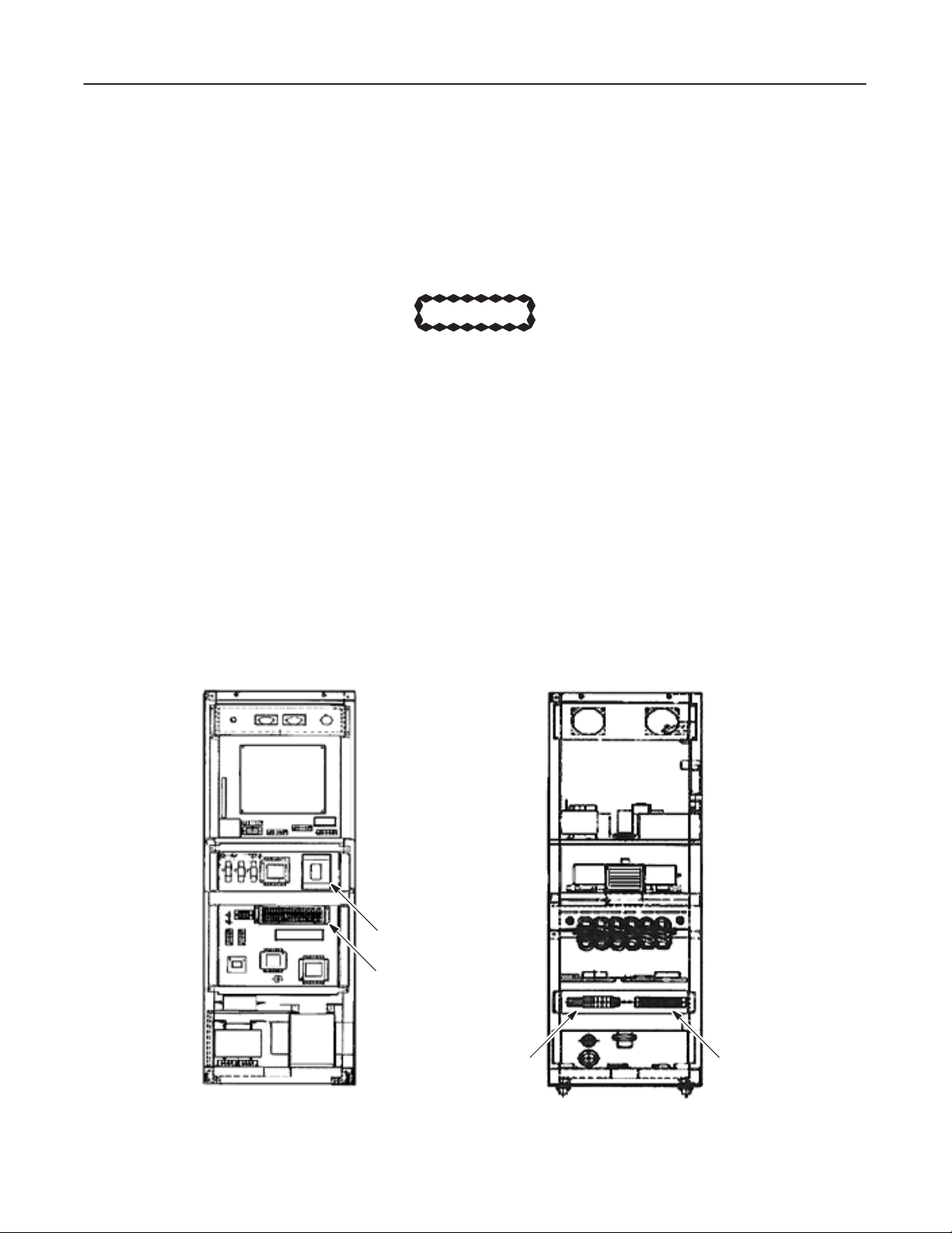
1-1 CHECK
This
section assumes all wiring and cabling is complete, equipment is installed, and that the following circuit
and switches are OFF.
PRIOR T
O APPL
YING POWER
CAUTION
Leave all power to the System OFF and tagged until power is called for in a specific step.
D
BREAKER IN P
D
6 BREAKERS (CB 1 – 6) in XG cabinet
D
4 REAR BREAKER SWITCHES (SW 1 – 4) and 1 BREAKER (NFB) in Gantry
.D.B (Power Distribution Box) for hospital supply
(NFB is only for System with T
able P9155AF)
2234976
breakers
D SER
D
D
Illustration 1–1
VICE SWITCH in Gantry
SYS–OFF–MNL SWITCH in Gantry
2 BREAKERS (NFB1, 2) in OC
XG Cabinet
CB6
CB1∼CB5
TM1 TM2
SYSTEM1–1
Page 20
GE MEDICAL
SYSTEMS
CT SYTEC/SYTEC I SERIES
FUNCTIONAL
CHECK /
ADJUSTMENT
REV 0
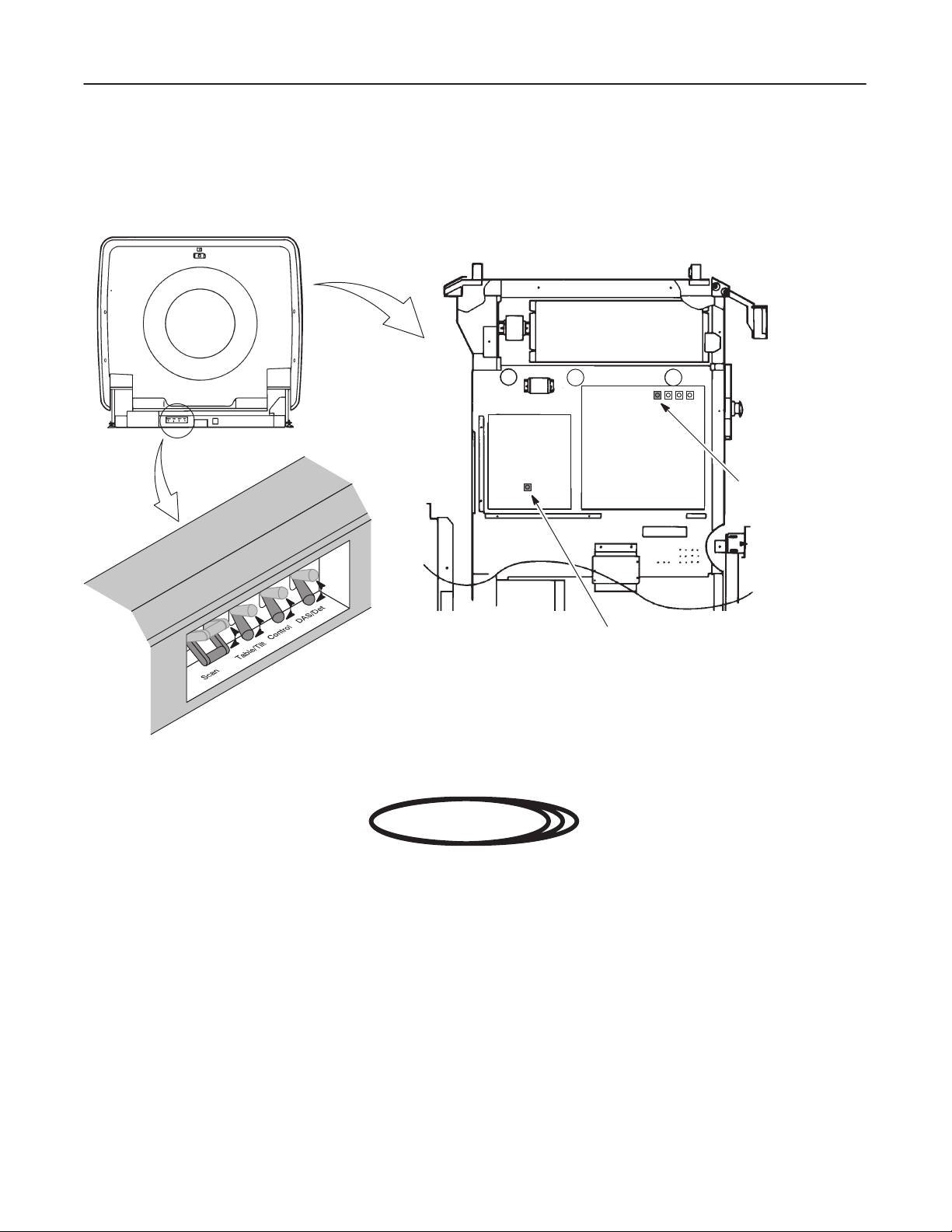
1-1
CHECK PRIOR T
Illustration 1–2
O APPL
Gantry
2234976
YING POWER (continued)
Servo Amp
Sub Board
TGP Board
Service Switch
(SYS/OFF/MNL)
Service Switch
DANGER!!
FATAL COLLISION HAZARD!!
WHEN ‘CONTROL’ SWITCH LOCATED ON THE GANTRY REAR BASE IS
TURNED ON (WITH THE ‘SCAN’ SWITCH ON), THE GANTRY WILL ROTATE
DUE TO INITIALIZATION.
Note
The ‘Scan’ and ‘TBL/Tilt’ switches must be turned ON before turning ‘Control’ switch ON. The
switches
turning ON sequence is as follows:
‘Scan’ ON ––> ‘TBL/T
ilt’ ON ––> ‘Control’ ON
The ‘DAS/Det’ switch ca be turned ON any time.
SYSTEM1–2
Page 21
GE MEDICAL
SYSTEMS
CT SYTEC/SYTEC I SERIES
FUNCTIONAL
CHECK /
ADJUSTMENT
REV 0
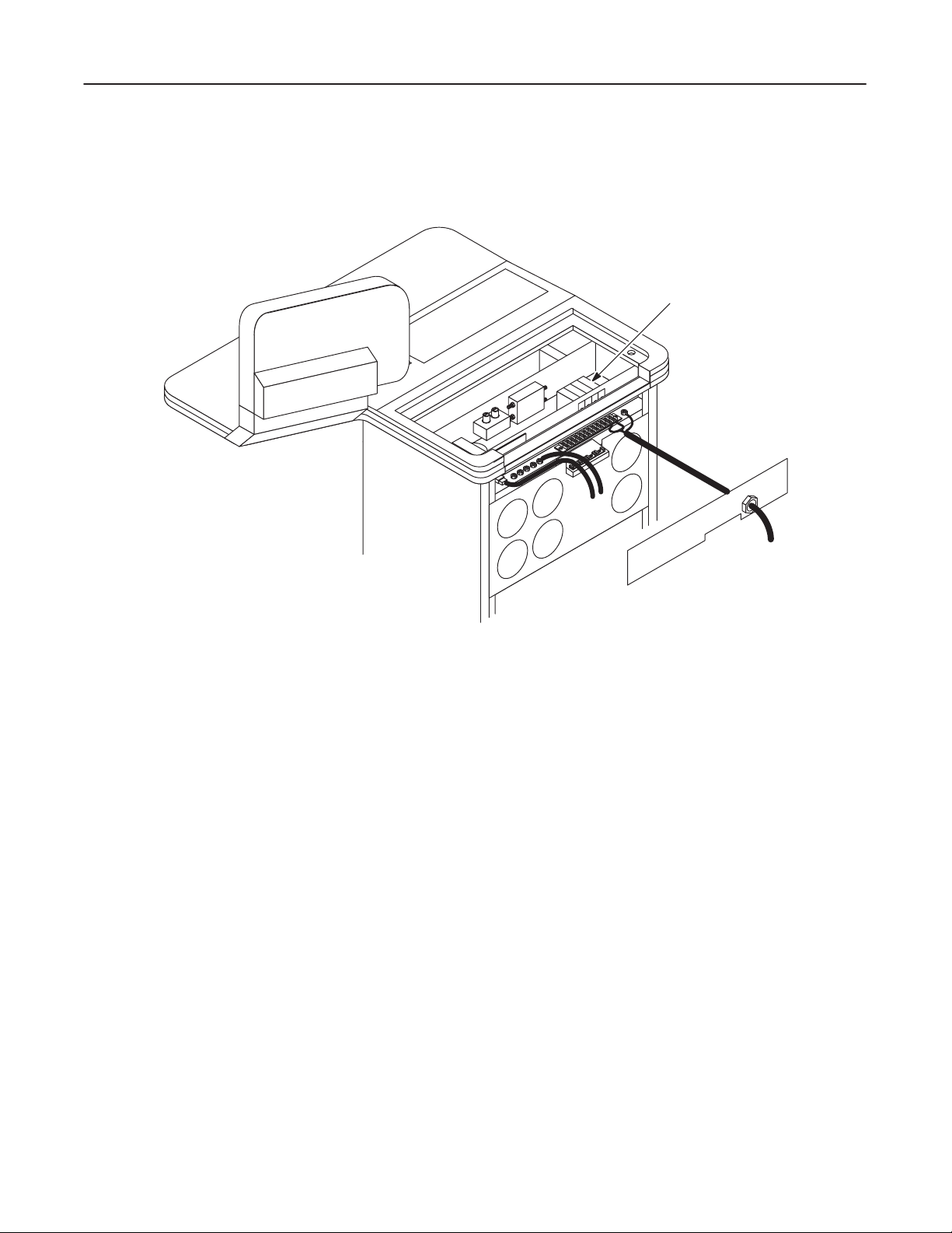
1-1
CHECK PRIOR T
Illustration 1–3
O APPL
YING POWER (continued)
Operator Console
2234976
NFB1, NFB2
SYSTEM1–3
Page 22

GE MEDICAL
SYSTEMS
CT SYTEC/SYTEC I SERIES
FUNCTIONAL
CHECK /
ADJUSTMENT
REV 0
1-2
GROUND CONTINUITY CHECK
V
erify that you removed the four(4) tilt lock plates and pulled out the Gantry azimuth lock pin.
1. Review illustration xxx, SYSTEM GROUNDING DIAGRAM schematics in the Installation Manual (P9018AS),
and
check that all connections are mechanically secure at both ends.
2.
Use a multimeter of equivalent device to measure the DC resistance between the following components in the
System, and verify that the resistance of each is less than
Ground specifications ≤ 0.1
T
able 1–4
GND (PDB)
GND (XG) GND (GANTRY)
GND (GANTRY) GND (TABLE)
Ground Continuity Check
FROM TO Resistance
Ω.
GND (XG)
0.1Ω.
(Ω)
2234976
GND (XG) GND (OC)
GND (OC) GND (MT)*
GND (OC) GND (MFC)*
GND (OC) GND (OD)*
GND (OC)
Note:
* indicates optional components.
GND (Advantage Windows)*
SYSTEM1–4
Page 23

GE MEDICAL
SYSTEMS
CT SYTEC/SYTEC I SERIES
FUNCTIONAL
CHECK /
ADJUSTMENT
REV 0
1-3 TEMPERATURE
During the installation and start–up of the system you must take continuous temperature checks to make sure the
environment meets specifications listed in Section 3 of the Preinstallation manual (P9018AR). Excessive temperature,
coupled with reduced air flow from clogged filters, may overstress components and cause failures.
Filters
Check
and clean all electronic equipment dust filters. GE recommends initially doing this on a weekly basis, because
new installations
nance
interval as site environment improves.
Specifications
During installation, use the temperature/humidity recorder and thermometer to record the temperature and relative
humidity
tions.
in the scanner room. Make sure the data you collect meets the following temperature and humidity specifica
D Scanner
always have dust and dirt present at this stage. Over a period of time, you may increase the mainte
Room
–T
emperature :
20°C ∼
28
°C
2234976
-
-
Action
Contact
tions.
–
Relative Humidity :
D Operator’
the air conditioning supplier or your local GE service department when your data fails to meet any specifica
s Room and/or Equipment Room
–T
emperature :
–
Relative Humidity :
40% ∼ 70% (Non Condensing)
15°C ∼
20% ∼ 80% (Non Condensing)
30
°C
-
SYSTEM1–5
Page 24
GE MEDICAL
REV
0
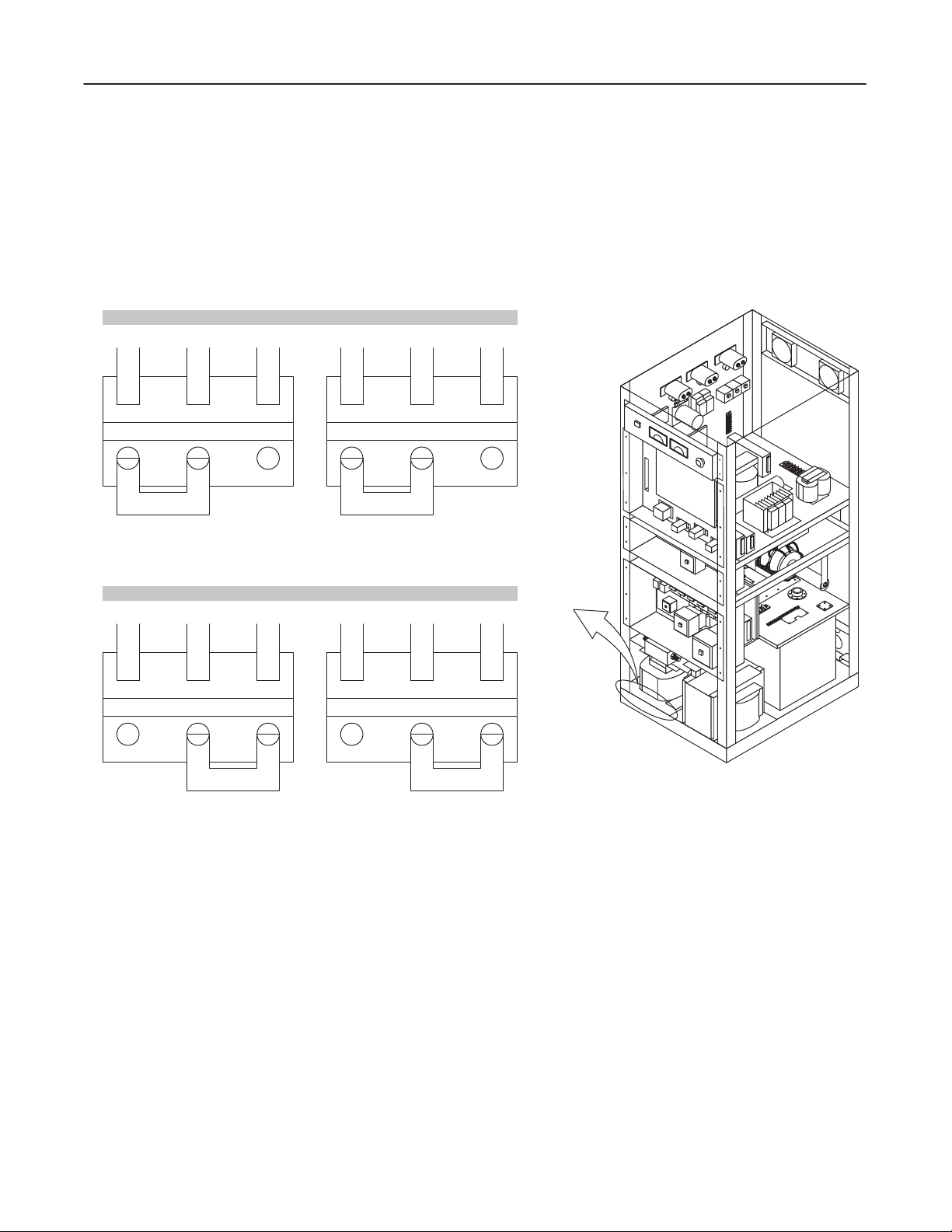
1-4
POWER LINE VOL
Input Selection of 200V or 208V
V
erify that the following connections in X–Ray Generator meet the input power voltage.
SYSTEMS
FUNCTIONAL
TAGE
CT SYTEC/SYTEC I SERIES
CHECK /
ADJUSTMENT
2234976
Illustration 1–5
TM3 TM4
200V C 208V 200V C 208V
TM3 TM4
200V C 208V 200V C 208V
V
oltage Selection
For 200V System
For 208V System
SYSTEM1–6
Page 25

GE MEDICAL
SYSTEMS
CT SYTEC/SYTEC I SERIES
FUNCTIONAL
CHECK /
ADJUSTMENT
REV 0
1-4
POWER LINE VOL
The
following assumes that the power source for the system was checked for mean voltage, as well as any line
disturbance
Instrument
Use
the same instrument (Dranetz, etc.) to monitor line voltage during this check that you used during the preinstalla
tion
check. The recommended line analyzer is
or Dranetz Model line monitor plug in modules. Y
mean voltage, surges, sags, short term impulses, and frequency drift.
Check Using an Instrument
Monitor the input power lines (200V
during preinstallation site checks.
D V
erify that the current line voltage equals the voltage measured during the preinstallation check.
D Verify
that mean line voltage does not fall outside of equipment specifications during the day to day opera
tion
of other site equipment during the installation period.
TAGE (continued)
AC or 208V
the Dranetz Model 606–3 (3 channel) with the 101 frequency option,
ou can use a
AC) to the System at the System. Check in particular:
similar analyzer
, as long as it can monitor and report
2234976
voltage
-
-
D Look
From the printouts, ensure that the power supply meets the following criteria :
Check Using an Oscilloscope
Monitor
between the oscilloscope’
harmonics of the third, seventh, and eleventh derivative will be the most prevalent.
Action
Investigate any condition that falls out of spec. Identify the problem source(s) and resolve the problem.
the power lines with an oscilloscope and verify that no significant distortion, noise or transients exist. Switch
for any line voltage disturbances and check for a correlation between disturbances and system mal
functions
D
Line V
D
Daily V
D Frequency :
such as “Aborts” or component failures.
oltage :
oltage V
ariation :
s long and
200V
AC (50 Hz/60 Hz) (Normal Steady State)
208V
AC (60 Hz) for U.S.A. (Normal Steady State)
+10% to –5% from nominal steady state (50Hz)
+6% to –9% from nominal steady state (60Hz)
50Hz ± 0.5Hz, 60Hz ± 0.5Hz
short
time base to monitor for spikes, as well as line drift over time. Generally
-
,
SYSTEM1–7
Page 26

GE MEDICAL
REV
0
1-5 LOAD DISTRIBUTION
Before
attempting this power application and functional check,
instructions
SYSTEMS
given in ‘Checks prior to Applying Power
ELECTRIC SHOCK HAZARD !!
DANGEROUS
TO
PERSONNEL AND EQUIPMENT
VOLTAGES EXIST WITHIN THE UNIT
.
make sure that the breakers and switches match the
.’
WARNING!
, USE EXTREME CARE TO A
CT SYTEC/SYTEC I SERIES
FUNCTIONAL
CHECK /
VOID INJUR
ADJUSTMENT
2234976
Y
Follow this procedure
Follow this sequence to protect you and the equipment from irreparable damage.
1. Preparation
a.
Remove the following covers:
D XG Covers (front and rear)
D OC Covers (front and rear)
D T
able Bottom Cover
D
Gantry Left side Cover
b. V
erify again that all breakers and switches are OFF according to ‘Checks prior to Applying Power
c. V
erify that wiring and cabling are correctly connected.
d.
2.
Switch ON the breaker on the power distribution box (hospital supply).
3.
Measure 200 (or 208) V
It should be
4.
Switch ON the ‘TRANS’ (CB1) breaker on the XG.
exactly
200 (or 208) ± 20V
in the order it was written. This procedure was developed with your safety in mind.
AC between terminals 1 and 2 (or 2 and 3) on TM1 on the XG.
AC.
.’
V
erify that the ‘Power
5.
Switch ON the ‘DAS’ (CB3) breaker on the XG.
6.
Measure 100V
7.
Push the ‘Power
Listen for the sound of contactor K1, K2 and K3 actuating in the XG. Check that the plunger indicators on K1,
K2
and K3 are pulled into the relay bodies.
AC between terminals 6 and 7 on TM2 on the XG. It should be
’ lamp in the front upper left corner of the XG turns ON.
’ switch on the OC.
100 ± 10V
AC.
SYSTEM1–8
Page 27

GE MEDICAL
SYSTEMS
CT SYTEC/SYTEC I SERIES
FUNCTIONAL
CHECK /
ADJUSTMENT
REV 0
1-5 LOAD DISTRIBUTION (continued)
8. Switch
9. Push
On the ‘OC’ (CB5), ‘TG1
voltages:
D 100 ±
D 115 ± 11.5VAC
D 200
the ‘Power
10V
AC
(or 208) ± 20V
’ switch on the OC. V
15’ (CB4) and ‘TG200/208V’ (CB2) breakers on the XG, and
.
. . . . . . . . . . . . . . . . . . . . . . .
. . . . . . . . . . . . . . . . . . . . . .
AC
.
. . . . . . . . . . . . . .
FATAL COLLISION HAZARD !!
WHEN BREAKERS LOCATED ON THE GANTRY REAR BASE ARE TURNED
ON, ALWAYS TURN THE SWITCHES ON IN THE FOLLOWING ORDER.
‘SCAN’ ON → ‘TABLE/TILT’ ON → ‘DAS/DET’ ON → ‘CONTROL’ ON
(CONTROL SWITCH MUST BE TURNED ON LASTLY.)
check the following
between terminals 10 and 1
between terminals 4 and 5 on TM2 (for TG1
between terminals 1 and 2 (2 and 3) on TM2 (for TG200/208V)
erify that the K1, K2 and K3 are turned OFF
1 on TM1 (for OC)
15V).
.
DANGER!!
2234976
FAILURE TO HEED THIS WARNING MAY LEAD TO GANTRY ROTATION AND
RESULT IN PERSONAL HARM, HARM TO OTHERS OR DEATH.
10. Switch
ON all breakers and switches according to ‘Checks prior to Applying Power
FATAL COLLISION HAZARD !!
VERIFY
THA
T NO PEOPLE ARE IN THE SCAN ROOM. THE GANTR
AUTOMATICALLY IMMEDIATELY AFTER THE OC POWER SWITCH IS
TURNED
ON. WHEN THE GANTR
CAN BE CAUGHT IN THE GANTRY. FAILURE TO HEED THIS WARNING MAY
RESULT IN PERSONAL HARM, HARM TO OTHERS, OR DEATH.
11. Push
the ‘Power
V
erify that the ‘OC Power
V
erify that the 16 Fans rotate properly
’ switch on the OC.
.’
DANGER!!
Y ROT
Y COVERS HA
’ lamp turns ON, and ‘System Preparation’ is displayed on the CR
.
VE BEEN REMOVED,
ATES
PEOPLE
T monitor
.
D Six(6) Fans
D Nine(9) Fans
D One(1) Fans
.
. . . . . . . . . . . . . . . . . . . . . . . . .
.
. . . . . . . . . . . . . . . . . . . . . . . .
.
. . . . . . . . . . . . . . . . . . . . . . . .
upper rear part
bottom side of the nest chassis
behind power supplies
SYSTEM1–9
Page 28

GE MEDICAL
REV
0
1-6
EMERGENCY OFF TEST
1.
Press the emergency switch on the OC.
Verify
tector).
SYSTEMS
that contactor K1, K3 and K4 in the XG turn OFF
FUNCTIONAL
, and cut the power to the T
CT SYTEC/SYTEC I SERIES
CHECK /
able/Gantry (except DAS/De
ADJUSTMENT
2234976
-
2. Press
There are two emergency switches on the Gantry and one emergency switch on the XG. Perform this emergency
OFF
1-7 FILTER
There are on Filter in the OC and two in the XG.
1.
2.
3.
4.
1-8 CUST
the ‘Power
test on each on the three emergency switches.
D
OC : Horizontal. one on the bottom of OC –– housed within a gold mesh filter enclosure.
D
XG : V
Slide the filter at the bottom of the OC forward until it is removed from the OC.
Remove the front and rear covers of the XG and gentry pull the the foam out of each enclosure.
Suck up any dust on the filters with a vacuum cleaner
Slide or fit each filter back into its enclosure.
OM P
’ switch twice to reset emergency OFF
ertical, one each on the front and rear cover –– foam held in place by a white mesh enclosure.
ARAMETER
, and re–apply power
.
.
Run
the Custom Parameter program to set the correct system configuration. Y
you
change the system configuration (adding the option, etc.).
Refer to Functional Check/Adjustment manual, System, Section 2.
Note
No image data must exists on the system hard disk if you set or change the following parameters.
–
Optical Disk Option
–
Magnetic T
– Frequency
–
Machine Number
–
Hospital Name
BOOT floppy must be in the floppy disk drive to change the parameters.
ape Option
Note
ou must also
run this program any time
SYSTEM1–10
Page 29

GE MEDICAL
SYSTEMS
CT SYTEC/SYTEC I SERIES
FUNCTIONAL
CHECK /
ADJUSTMENT
REV 0
1-9 X–RA
Check the overheat detection function by performing the following:
1.
2.
3.
4.
5. T
Y TUBE OVERHEA
Switch OFF the ‘Scan’ switch at the Gantry rear base
Remove the both side covers from the Gantry
Disconnect the rotor cable.
If the connector is not accessible, perform the following:
a.
Set the Service switch to ON on the SUB Board.
b.
Rotate the Gantry until the X–ray tube reaches the 3 o’clock position.
c.
Set the Service switch to OFF
Switch ON the ‘Scan’ switch.
ry to perform a scan.
V
erify that a scan can not be performed and the “XG Fail” error message is reported on the status screen.
T SAFETY
.
.
2234976
V
erify that the ‘OH’ LED on the Power CONT Board in the XG is illuminated.
6.
Switch OFF the ‘Scan’ switch.
7.
Reconnect the connector
.
SYSTEM1–11
Page 30

GE MEDICAL
SYSTEMS
CT SYTEC/SYTEC I SERIES
FUNCTIONAL
CHECK /
ADJUSTMENT
REV 0
1-10
SCAN TEST
This
check assumes successful completion of all functional checks for XG, Gantry T
tec
i series Operator Manual for scanning operation instructions.
DANGER!!
X–RAY EXPOSURE !!
IN
THIS SECTION, THE X–RA
THAT
Warm
Up Scan
1.
Make sure system power is ON an the ‘New Patiant’ and the ‘W
NO PEOPLE IS IN
‘W
arm Up’ should blink just after power up or system reset.
THE SCAN ROOM WHENEVER SCAN IS PERFORMED.
Y EXPOSURE IS PERFORMED. ALWAYS VERIFY
arm UP’ arear are blinking on LCD screen.
Note
2234976
able and OC. Check CT Sytec/Sy
-
2.
Make sure mothing is in the scan arear in the Gnatry room.
3. T
ouch the ‘W
Make sure all warm up scans complete without error
aum Up’ prompt to start the tube warm up program.
.
SYSTEM1–12
Page 31

GE MEDICAL
SYSTEMS
CT SYTEC/SYTEC I SERIES
FUNCTIONAL
CHECK /
ADJUSTMENT
REV 0
1-10 SCAN TEST (continued)
Scoutview Scan
4.
Perform a series of scout scans to check scout scan operations:
Use the following scan parameters:
FOV
mA
Tilt
a.
Make sure that each scan is completed successfully
b. T
ilt the Gantry to any angle.
Make sure the software prohibits a scout scan with the Gantry tilted.
c.
Release the ‘Scan ’ button during a scout scan.
V
erify it aborts X–ray radiation, rotor rotation and cradle movement.
: 42 cm
: 40, 60 or 80 mA
: 0
°
2234976
.
d.
Select Auto V
Lay the water phantom horizontally on the cradle.
Perform an AP (0°) scout scan on the phantom.
Make sure that you can hear and understand each voice.
V
erify that the phantom diameter (In–Out direction) on the image is
e.
Select Auto V
Set the QA phantom on the phantom holder
Perform a L
Make sure that you can hear and understand each voice.
Release the ‘Scan’ button before the whole image is displayed and verify that the scan continues.
Push the ‘Abort’ key and verify that the cradle and scan stop.
oice S1 and Auto V
oice S2 and Auto V
T (90°) scout scan on the phantom.
oice E1.
oice E1.
.
266mm ± 3mm
.
SYSTEM1–13
Page 32

GE MEDICAL
SYSTEMS
CT SYTEC/SYTEC I SERIES
FUNCTIONAL
CHECK /
ADJUSTMENT
REV 0
1-10 SCAN TEST (continued)
Localize
5.
Perform a Localize function:
a.
Display a scout image (use the image acquired at step 4).
b.
Select the Localize function.
c.
Prescribe and confirm an axial scan plan.
Make sure theat the ‘T
d.
Press the ‘T
Check that the cradle advances to the prescribed position.
Axial Scan
able Set’ button.
2234976
able Set’ button blinks.
6.
Perform an axial scan to check axial scan opreation:
Use the following scan parameters:
Interval : +10.0mm
Scan T
a.
Select each of the Auto V
V
erify that each scan completes with no error occurred.
V
erify that you can hear and understand each voice.
Recon Time
7.
Perform an axial scan using the following scan parameters:
Scan T
Scan FOV
Recon FOV
Recon Mode
Anatomic Region
ime : 3.6 sec
2.7 sec
1.8 sec
ime : 3.6 sec
(CT Sytec 2000i, S)
(CT Sytec, 3000i)
(CT Sytec 4000i, Plus)
oice messages (S1, S2, S3, S4, S5 or S6).
2.7 sec
1.8 sec
:
25 cm
:
25 cm
: STND
: Head
(CT Sytec 2000i, S)
(CT Sytec, 3000i)
(CT Sytec 4000i, Plus)
V
erify that the time between the scan end and the image appearance on the CR
T monitor is within
15 sec
SYSTEM1–14
.
Page 33

GE MEDICAL
SYSTEMS
CT SYTEC/SYTEC I SERIES
FUNCTIONAL
CHECK /
ADJUSTMENT
REV 0
1-10 SCAN TEST (continued)
KV and mA Meter
8.
Perform a series of axial scans (mA : 40, 60, 80, 100, 130 and 160).
V
erify that the KV meter on the XG read
Also verify that the mA meter on the XG reads the expected value ± 5%
Abort
9.
Perform an axial scan and press the ‘Abort’ button before the scan completes.
V
erify that the scan is terminated.
120KV ± 3KV
.
2234976
.
SYSTEM1–15
Page 34

GE MEDICAL
SYSTEMS
CT SYTEC/SYTEC I SERIES
FUNCTIONAL
CHECK /
ADJUSTMENT
blank
2234976
SYSTEM1–16
Page 35

GE MEDICAL
SYSTEMS
CT SYTEC/SYTEC I SERIES
FUNCTIONAL
CHECK /
ADJUSTMENT
REV 0
2-1 GENERAL
Save
existing patient data any time you perform the LFC procedure or you will lose this data.
The saving procedure is described in section 2-3 Pre–ATINST Procedure, Saving Customer
Data.
For DC–X, the system must be running on at least version 5.00 software. If the customer ’s
DC–X
system is older than version 5.00, perform FMI (FM91015 or 91016) must be performed
(version
2234976
SECTION 2 – SOFTWARE LOADING
NOTICE
NOTICE
5 upgrade) first.
This
section describes the
Disk)
to system hard disk. Perform this LFC procedure when:
D A failure or crash corrupts the hard disk so the existing software can not be used. A Load–From 0Cold
rebuilds
D CT Engineering has revised the current software to incorporate improvements or correct existing prob-
lems.
Replace the old software by performing a Load–From–Cold with the new software.
Load–From–Cold (LFC) procedure for a full system software loading from some FD (Floppy
the operating software on the disk and restores normal system operation.
SYSTEM2–1
Page 36

GE MEDICAL
SYSTEMS
CT SYTEC/SYTEC I SERIES
FUNCTIONAL
CHECK /
ADJUSTMENT
REV 0
2-1 GENERAL (continued)
Illustration 2–1
•
‘Acq Reverse’ Data
•
Communication Data
•
Ethernet Data
•
Station Data
•
Raw Data Files
•
Patient Image Data
•
Error Message Help
•
Record the Custom Parameters –––––
Load–From–Cold Standard Procedure
Start
Save Customer Data
– Start Study No.
– Direction of Scout Image (Apex / Lateral)
– Gantry Direction from Operator
Set CPW Boot Dip Switch
Insert Boot Floppy
Pull Reset Switch
A
TINST Program
2234976
•
Data File Save –––––––––––––––––––––
•
Disk Initialize
•
Software Loading (Standard, Option)
•
File Allocation
•
Data File Loading
Starting Up System
•
Remove Floppy Disk
•
Reset CPW Dip Switch
•
Pull Rest Switch
Restore Custom Parameters
•
Including Additional Option Software Loading
•
Custom Parameter Change
(It is necessary to manually restore the parameters due to a software bug.)
– Start Study No.
– Direction of Scout Image (Apex / Lateral)
– Gantry Direction from Operator
Restore Customer Data
•
‘Acq Reverse’ Data
•
Communication Data
•
Ethernet Data
•
Station Data
•
Raw Data Files
•
Patient Image Data
•
Error Message Help
– Calibration Files
– Station No. Information
– Preset Patients Information
– Scan Parameter
– System Parameters (Custom Parameters, etc...)
End
SYSTEM2–2
Page 37

GE MEDICAL
SYSTEMS
CT SYTEC/SYTEC I SERIES
FUNCTIONAL
CHECK /
ADJUSTMENT
REV 0
2-2
FD FOR SYSTEM/OPTION SOFTW
Prepare the following, prior to starting the LFC procedure.
T
able 2–1
System Software Diskettes
V
olume Name
ARE
BOOT 0
KEY0 1
LO00 2
LO10 3
LO20 2
LO21 2
LO30 3
LO31 2
LO40 2
2234976
Revision
LO41 2
LO42 2
LO43 3
HO00 4
CT00 3
CT10 2
VC00 2
TD00 3
OP00 0
OP01 0
OP02 0
OP03 0
OP04 0
PL00 (for CT Sytec 4000i, Plus)
ST00 (for CT Sytec, 3000i)
BS00 (for CT Sytec 2000i, S)
4
4
4
V400 (1/5 ∼ 5/5)
V400 (for CT Sytec 4000i, Plus)
V400 (for CT Sytec, 3000i)
V400 (CT Sytec 2000i, S)
0
0
0
0
SYSTEM2–3
Page 38

GE MEDICAL
N
Volume
R
N
SYSTEMS
CT SYTEC/SYTEC I SERIES
FUNCTIONAL
CHECK /
ADJUSTMENT
REV 0
2-2
FD FOR SYSTEM/OPTION SOFTW
T
able 2–2
Volume
o.
Name
1 PZ00 1
2 PG10 1 Paging F F f
3 CVRF 2
4 RTRF 2
5 DIND 1
6 DIM3 1
7 CD00 2 Coordinate f f f
8 DENT 2
9 ELNK 1
Option Software Diskettes
ev.
Pan / Zoom
Curved Reformation
Real T
ime Reformation
Display in Display
3D Imaging
Denta Scan
Ethernet Link
ARE (continued)
ame
Sytec 4000i, Plus
F F f
F F f
F F f
F f f
f f f
f f f
f f f
Option or Standard
Sytec, 3000i
Sytec 2000i, S
2234976
10 INST 0 InSite f f f
11 BMD0 1 BMD f f f
12 CCI0 0 CCI f f f
13 FI00 0
F
: Standard
f
: Option
Normally, option software disks and also some application software disks included in the system software (‘PG00’
disk,
‘PZ00’ disk, ....) are
if the A
TINST program (described later) failed, or when the system hard disk drive is replaced with a new one.
Functional Image
: The system includes the software.
: The system does not include the software.
not required in a version up or a re–loading procedure. However
f f f
, these disks are required
SYSTEM2–4
Page 39

GE MEDICAL
REV
0
SYSTEMS
CT SYTEC/SYTEC I SERIES
FUNCTIONAL
CHECK /
ADJUSTMENT
2234976
2-3 PRE–A
Save Customer Data before proceeding. You must load Customer Data onto floppy diskette, tape or optical disk
cartridge because the LFC (Load–From Cold) procedure destroys any information on the system disk. Refer to the
Operator Manuals to complete the following steps.
1.
Record ‘Acq Reverse’ user setting parameter
a. After displaying an image on the CRT screen, write down ‘Acq Reverse’ data (ON or OFF) in ‘Set
2.
Save Communication Data.
For any system on which ELINK is installed, save Communication Data, Station No. and Ehternet Data on a
floppy
a.
TINST PROCEDURE
Note
Alphanumeric letters you must enter at the keyboard are underlined. ‘CR’ means press the ‘Enter
.
function.
Note
Usually
matically in the A
be
Press the [Mgt] key
the parameter setting data does not need to
TINST program (Data File Save Function). However
recorded due to a software bug.
disk. Otherwise, these data will be deleted during LFC.
.
be recorded, since the data will be saved auto
, only ‘Acq Reverse’ data
must
’.
Display’
-
D
Select Communication Data Load/Save → Save
D
Select Ethernet Data Handling → Save to FD
D
Select Dump Parameters → Station Number Information File
Note
When saving all information above, use on floppy disk.
SYSTEM2–5
Page 40

GE MEDICAL
SYSTEMS
CT SYTEC/SYTEC I SERIES
FUNCTIONAL
CHECK /
ADJUSTMENT
REV 0
2-3 PRE–ATINST PROCEDURE (continued)
NOTICE
If
you intend to save raw data on MOD, e sure to start with a blank cartridge, or one that does
not
need to be preserved. This procedure erase all previous data contained on
tridge.
3. Save
Raw Data Files:
Archive
wise,
Use the ‘Maintenance’ function to save the Raw Data as follows:
a.
b.
c.
d. V
Raw Data Files to a MOD, floppy
these files are destroyed during LFC.
Select
Select
Record the ID number of the Raw Data Files which you want to save.
Support
FD Dump/Load, MT Dump/Load
erify that the MOD should be set “write enable”.
from the Maintenance menu.
disks, tape, or optical disk if the customer wants to save them. Other
, or
MOD Dump/Load.
the MOD car
2234976
-
-
e.
Select
f.
Select
g.
Enter all the Raw Data File ID numbers. Then press the [End] key
4.
Save Patient Image Data:
Archive Patient Image Data to a MOD, floppy disks, tape, or optical disk if the customer wants to save them.
Otherwise,
Data. (Refer to Operator Manual.)
5.
Check if the service maintenance menu includes ‘
If
the system contains ‘Error Message Help’ function, it must be reinstalled since version–up or reloading proce
dures
Initialize
Dump (Disk –> MOD)
these files are destroyed during LFC. Use the ‘Image File Management’ function to save the Image
delete it.
to initialize the MOD.
.
.
Error Message Help
’.
-
SYSTEM2–6
Page 41

GE MEDICAL
SYSTEMS
CT SYTEC/SYTEC I SERIES
FUNCTIONAL
CHECK /
ADJUSTMENT
REV 0
2-3 PRE–ATINST PROCEDURE (continued)
6.
Record Customer Parameters.
Usually the Customer Parameter Data does not need to be recorded, since the data will be saved
automatically
rameters
D
Start Study No.
D Direction of Scout Image (Apex)
D
Direction of Scout Image (Lateral)
D
Gantry Direction from Operator
Also,
it is recommended to check which option software are currently installed
you
can confirm later that those option software have been correctly retrieved. In addition, if you nave
all
the records, they con serve as backup in the event there is trouble with the A
a.
Select
in the A
must be recorded due to a software bug.
Custom Parameters
TINST program (Data File Save Function). However
from the Maintenance menu.
Note
Note
, at least the following pa
on the system, so that
TINST program.
2234976
-
b.
Select
Custom
ters.
Custom
Therefore, enter the
Display Parameters
Parameters will be displayed
Parameters include Function Menu which noes not show in the Display Parameters mode.
.
one by one, as listed in T
Change Parameters
able 2–3. Use this table to record the parame
mode and record the parameters in T
-
able 2–4.
SYSTEM2–7
Page 42

GE MEDICAL
SYSTEMS
CT SYTEC/SYTEC I SERIES
FUNCTIONAL
CHECK /
ADJUSTMENT
REV 0
2-3 PRE–ATINST PROCEDURE (continued)
T
able 2–3
Current Model Name
Auxiliary
Optical Disk
Magnetic Optical Disk
Magnetic T
Frequency
Machine No.
Hospital Name
Start Study No.
Disk Size
ape
Custom Parameters (Display)
Unavailable . A
Unavailable . A
Unavailable . A
Unavailable . A
50 . 60
2234976
vailable
vailable
vailable
vailable
Direction of Scout Image
Apex Lateral
Kind of Base
Gantry . Head
Gantry Direction from Operator
Head T
Postfossa T
Neck T
Thorax T
Abdomen T
Pelvis T
Extremities T
Thickness 2/3mm
Note1
: For Sytec 2000i and Sytec S system, this parameter is NOT displayed.
Picture Direction
Upper . Lower
Left . Right
Direction of Axial Image (from)
op . Bottom
op . Bottom
op . Bottom
op . Bottom
op . Bottom Infant – Abdomen
op . Bottom
op . Bottom
Infant – Head
Infant – Postfossa
Infant – Neck
Infant – Thorax
Infant – Pelvis
Infant – Extremities
2mm . 3mm
Kind of Base
Gantry . Head
Picture Direction
Upper . Lower
T
op . Bottom
T
op . Bottom
T
op . Bottom
T
op . Bottom
T
op . Bottom
T
op . Bottom
T
op . Bottom
(see Note1)
SYSTEM2–8
Page 43

GE MEDICAL
SYSTEMS
CT SYTEC/SYTEC I SERIES
FUNCTIONAL
CHECK /
ADJUSTMENT
REV 0
2-3 PRE–ATINST PROCEDURE (continued)
T
able 2–3
P
AN & ZOOM
PAGING
3D IMAGING
REAL–TIME REFORMA
CUR
VED REFORMA
BMD
COORDINATE
CALCULATOR
DENTA
DISPLA
NETWORK
Y IN DISPLA
Custom Parameters (Display) (continued)
TION
TION
Y
Option
Unavailable . A
Unavailable . A
Unavailable . A
Unavailable . A
Unavailable . A
Unavailable . A
Unavailable . A
Unavailable . A
Unavailable . A
Unavailable . A
Unavailable . A
2234976
vailable
vailable
vailable
vailable
vailable
vailable
vailable
vailable
vailable
vailable
vailable
SET LANGUAGE TYPE
INSITE
No. of Raw Data
Note2
: This parameter is displayed at the system o version 3.01 or later
T
able 2–4
Auto Store Device Option
OD Special Store Option
Auto Delete Option
Min. V
acant Image Space for Scan
FD Packing Option
MT Packing Option
OD Packing Option
FD System No.
MT System No.
OD System No.
Custom Parameters (in Change Mode)
Function Menu
Unavailable . YMS E–LINK
English . French (see
OD . MT . MOD
NON . AUT
ON . OFF
DPCM . ORIGINAL
DPCM . ORIGINAL
DPCM . ORIGINAL
Note2)
.
O
MT Image Max. No.
Device T
Note3
ype of Optional Disk
: This parameter appears only if both OD and MOD are installed.
128 . 256 . 384 . 512 . 640 . 768
OD . MOD
(see Note3)
SYSTEM2–9
Page 44

GE MEDICAL
SYSTEMS
CT SYTEC/SYTEC I SERIES
FUNCTIONAL
CHECK /
ADJUSTMENT
REV 0
2-3 PRE–ATINST PROCEDURE (continued)
7.
Save data files (Preset Patient Information, Series Description, ....)
Note
Usually
in
trouble with the A
D
D Series
D Calibration
D Station
the sets of information below do not need to be saved since they will be automatically saved
the A
TINST program. However
, if you save them, they can serve as backup in the event there is
TINST program.
Preset Patient Information
Description
Files
No. Information
.
. . . . . . . . . . . . . . . . . .
.
. . . . . . . . . . . . . . . . . . . .
.
. . . . . . . . . . . . .
.
. . . . . . . . . .
Select
Select
Select
Select
Dump Parameters
Dump Parameters
Dump Parameters
Dump Parameters
Note
Do not save the System
has
been retried, system might hang–up.
Parameter
. If the backup system parameter will be restored after ATINST
2234976
from the Management menu.
from the Management menu.
from the Management menu.
from the Management menu.
SYSTEM2–10
Page 45

GE MEDICAL
SYSTEMS
CT SYTEC/SYTEC I SERIES
FUNCTIONAL
CHECK /
ADJUSTMENT
0REV 0
2-4 ATINST
Introduction
ATINST
BOOT
program performs the following operations on after another automatically
floppy performs the most of the LFC procedures, as described below:
D
Data File Save
The
following data is automatically saved to the floppy disks. Prepare a few (1 ∼ 4) blank floppy diskettes
before
starting A
–
–
–
–
–
–
TINST.
Calibration Files
Station Number Information
Preset Patient Information
Series Description
Scan Parameter
System Parameters
Custom Parameters
Window / Level Key Settings
W/L Menu Settings
Set Display Settings
Image Sequence Settings
. The program A
2234976
TINST included in
D
Disk Initialize
D Software Loading (Standard, Option)
Additional option software will be installed during the ‘Restore Custom Parameters’ procedure.
D
File Allocation
File
Allocation create variable files for the system hard disk, such as image directory
image
data files. If consists of two phases as follow:
–V
ariable File Allocation (VRALCT)
Create blank image file directory and blank calibration files.
–
Image / Raw Data File Reserve (DFRSV)
Reserves contiguous sectors on the disk for image data and raw data.
D Data File Loading
The data stored on the FD at the first stage of the A
TINST in automatically loaded to the hard disk.
, calibration files and
SYSTEM2–11
Page 46

GE MEDICAL
SYSTEMS
CT SYTEC/SYTEC I SERIES
FUNCTIONAL
CHECK /
ADJUSTMENT
REV 0
2-4 ATINST (continued)
Failure Analysis of A
Each
of the A
to
have occurred while the A
The following error could occur during the execution of the A
If either of the above error occur
TINST operations are automatically called up after the previous procedure is finished. If an error seems
D T
est LED :
D T
est LED :
D TAL
D
******************************* Displayed *******************************
T LED :
An error of the A
TINST
TINST program is running, check the following LED’
When Test LEDs lit in 7x(h), it indicates that the program is accessing the hard disk or floppy
diskette.
When T
If lit, this LED indicates that the system operating system has terminated the current
command due to some error
It shows that the system is operating normally
est LEDs lit in D0(h), it indicates that a bus error has occurred. (abnormal state)
. (Abnormal state)
TINST program itself (Program abort due to a program bug or hardware failure)
, the following menu will be displayed:
2234976
s on the CPW board:
.
TINST program:
Current Task Aborted Unexpectedly
File Name : xxxx (a program name to which an error is occurred)
1. Exit INSTALLATION
2. Retry Current Task
Select Menu No. =
************************************************************************
Menu
1 :Terminates the A
Menu 2 :
If problems are unable to be fixed, type “A
Retry of A
After terminating the A
The ATINST program will start as ‘Reloading Mode’ or ‘First Loading Mode’, depending on when the program failed.
After the ATINST program is successfully finished, restore the following data files in that order, if they were saved.
Loading
order is very important.
Calibration Files
Station Number Information
Preset Patient Information
Series Description
Scan Parameters
Option software which the customer
InSite software (if system had)
Retries the program in which the error occurred.
TINST
TINST program by selecting ‘1’ in the menu, retry A
TINST program.
TINST” to resume A
’s system contains
TINST.
TINST.
SYSTEM2–12
Page 47

GE MEDICAL
SYSTEMS
CT SYTEC/SYTEC I SERIES
FUNCTIONAL
CHECK /
ADJUSTMENT
REV 0
2-4 ATINST (continued)
Operating ATINST
It will take approximately 40 minutes for the A
TINST program to complete all its operation.
NOTICE
Save existing patient data any time you perform a LFC procedure or you will lose this data.
The
saving procedure is described in ‘Pre–A
Prepare all of the floppy diskettes listed in T
1.
Set the SW2 and SW4 of the “BOOT” switches on the CPW Board (Slot #1) to the ON option.
Illustration 2–2
Boot Switch Setting on CPW Board
ON
TINST’ procedure.
Note
able 2–1 and T
able 2–2 before starting this procedure.
2234976
1 2 3 4
OFF
2.
Insert the BOOT floppy into the disk drive.
3.
Pull the reset switch located under the right side of the Operator Console.
The system is reset and “>” will appear on the monitor
4.
Start the A
******************************* Displayed *******************************
FHS ERROR C2
> ATINST ‘CR’
Delete IMAGE & RAW Data ? <0:OK, 1:Exit> = 0 ‘CR’
** INSTALLATION START **
Please Insert <<KEY0_[ x]>> FD and Press <ENTER>
************************************************************************
TINST program by entering A
TINST:
.
SYSTEM2–13
Page 48

CT SYTEC/SYTEC I SERIES
GE MEDICAL
REV
0
2-4 ATINST (continued)
5.
Remove the BOOT floppy from the floppy drive and insert KEY0 floppy supplied with the system.
SYSTEMS
FUNCTIONAL
CHECK /
ADJUSTMENT
2234976
Press the <Enter> key
******************************* Displayed *******************************
Please Insert FD for STORE and Press <ENTR>
************************************************************************
Always
prompted
The following operations are carried out automatically in the order described:
D
D
D
D
D
If a non–initialize floppy diskette is inserted, it will be initialized automatically before saving data.
use either blank floppies to store Data Files, or answer “Y
during ST
Saving Data files
Disk Initialize
Software Loading (Standard, Option)
File Allocation
Data File Loading
.
ORE.
Note
Note
es” to “Initialize OK
?” question when
6.
Save Data Files:
Remove
the scratch
the
7.
Initialize Hard Disk:
Remove the floppy diskette that data files are saved on and insert “BOOT” floppy diskette.
Press the <Enter> key
the KEY0 diskette, then insert the scratch floppy diskette with No.1 written on it. Y
floppy
disks in order according to screen messages to save data onto these disks. Be sure to number
floppies in the order used (1–4) for later reloading.
Note
If a non–initialize floppy diskette is inserted, it will be initialized automatically before saving data.
. This starts VINIT program so that the hard disk will be initialized automatically
******************************* Displayed *******************************
Please Insert <<BOOT>> FD and Press <ENTR>
** VNINTS Start **
What Device Name (4 Characters)? 463 MB Disk
** VINITs End
************************************************************************
.
.
.
ou only have to change
.
SYSTEM2–14
Page 49

CT SYTEC/SYTEC I SERIES
GE MEDICAL
REV
0
2-4 ATINST (continued)
8.
Software Loading (Standard, Option)
Remove the “BOOT” floppy diskette and insert the system floppy requests.
Press the <Enter> key. You only have to change the floppy disks to be loaded according to screen messages
until
SYSTEMS
all the floppies are loaded.
******************************* Displayed *******************************
** FD Loading Start **
Please Insert <<xxxx_[ x]>> FD and Press <ENTR>
SELECT No. 1 2 3 4
1: COPY 2: COPY AND VERIFY
3: VERIFY 4: VERIFY WITH COMMENT
.
.
.
FD Loading End
FUNCTIONAL
CHECK /
ADJUSTMENT
2234976
************************************************************************
9. File
Allocation
Inset the “BOOT” floppy diskette and press the <Enter> key
This start the file allocation program so that the variable files are created automatically
******************************* Displayed *******************************
** VR FILE ALLOCATION **
.
.
.
** VRALCT End **
** DFRSV Start **
.
.
** DFRRV End **
************************************************************************
.
.
SYSTEM2–15
Page 50

CT SYTEC/SYTEC I SERIES
GE MEDICAL
REV
0
2-4 ATINST (continued)
10.
Data File Loading
Remove the “BOOT” floppy diskette and inset No.1 floppy diskette that includes the parameters saved during
“Saving
11.
Replace the No.1 floppy diskette with No.2 and press the <Enter> key according to screen messages. Repeat
this procedure until all parameters are loaded.
12. After all FDs have been loaded, press the <End> key to terminate the Data File Loading. Then the following
screen
SYSTEMS
Data files” procedures at the first stage of A
will appears.
******************************* Displayed *******************************
** INSTALLATION END **
*************************************************
* We will complete all works for installation *
* Put back the Dip Switch (1–4:OFF) *
* and pull the Rest Button. *
* Don’t Forget other operations as follows: *
* (*) Retrieve Image & Raw Data *
* (*) Change CUSTOM PARAMETER if necessary *
*************************************************
TINST
. Then press the <Enter> key
FUNCTIONAL
CHECK /
.
ADJUSTMENT
2234976
************************************************************************
ATINST First Loading Mode
If the ‘first Loading Mode’ is used as ATINST, you have to respond to inquiry during the ATINST operations, as described
below
. This inquiries is on Model Name.
D
Model Name
Select the appropriate Model Name.
Y
ou will be instructed insert the ‘ST00’ or ‘BS00’ floppy
:
.
SYSTEM2–16
Page 51

GE MEDICAL
SYSTEMS
CT SYTEC/SYTEC I SERIES
FUNCTIONAL
CHECK /
ADJUSTMENT
REV 0
2-5 POST–A
Starting Up System
1.
Remove the floppy diskette that was used during data file loading.
2.
Set all bits of the “BOOT” switches on the CPW Board to the OFF position.
3.
Pull the system reset switch located under the right side of the Operator Console.
4. Check
Reinstall
If the system contains the InSite system, restore the InSite software.
TINST PROCEDURE
that the system status up normally and that the system version No. and loge appear on the CR
InSite Software
Note
The new INST floppy diskette must be prepared. Old software must not be reloaded.
Note
The system version 3 or later can not load InSite software using ‘Change Parameters’ mode of the
Customer Parameter
. Also so not use TCOPY when loading it.
2234976
T monitor
.
1.
Enter the Management menu by pressing [Mgt] key
2.
Insert the BOOT floppy disk.
3.
Enter $$
4.
Remove the BOOT floppy diskette and insert the INST floppy diskette.
5.
Enter the following at the “>” prompt:
6. Pull
7.
Check that the system starts up normally
and “>” prompt will be displayed.
******************************* Displayed *******************************
> FN INST:0.&.INSTINST.CF ‘CR’
> IC ‘CR’
************************************************************************
the system reset switch located under the right side of the Operator Console.
.
.
SYSTEM2–17
Page 52

GE MEDICAL
SYSTEMS
CT SYTEC/SYTEC I SERIES
FUNCTIONAL
CHECK /
ADJUSTMENT
REV 0
2-5 POST–ATINST PROCEDURE (continued)
Restoring Custom Parameter
Use the CHANGE P
to change the custom parameters;
to load additional option software;
to change the number of raw data files.
The
custom parameter data will be restored automatically in the ATINST program (Data File Loading
Function). However, regarding the following, it is necessary to manually restore due to a software
bug:
1.
Insert the BOOT floppy into the disk drive.
ARAMETERS function of the CUST
– Start
–
–
–
Study No.
Direction of Scout Image (Apex)
Direction of Scout Image (Lateral)
Gantry direction from Operator
OM P
ARAMETERS program for the following purposes:
Note
2234976
2. T
ouch the [Maint] key and enter $$
3.
Select
Custom Parameters
4.
Select
Change Parameters
If a parameter is not required to be changed, press the [END] key to proceed to the next item.
V
erify or change the custom parameters which are displayed one by one as listed T
When installing addition option software, the CUST
can
not be loaded using TCOPY
5.
Remove the BOOT floppy diskette.
6.
Pull the system reset switch located under the right side of the Operator Console.
7.
Check that the system start up normally
8. Using
‘Display Parameter
are
displayed as “Installed”.
’ of the CUST
to display the Maintenance menu.
from Maintenance menu.
Note
OM PARAMETER menu must be used. Note that software
.
.
OM P
ARAMETERS menu, check if all the optional software you installed
able 2–5.
SYSTEM2–18
Page 53

GE MEDICAL
SYSTEMS
CT SYTEC/SYTEC I SERIES
FUNCTIONAL
CHECK /
ADJUSTMENT
REV 0
2-5 POST–ATINST PROCEDURE (continued)
T
able 2–5
Set Model Name
Optical Disk
Magnetic Optical Disk
Magnetic T
Frequency
Machine No.
Hospital Name
Start Study No.
Scout Image Orientation
Gantry Direction from Operator
Axial Image Orientation (from)
ape
Custom Parameters (Change Mode)
This parameter does not appear if the hard disk contains images.
This parameter does not appear if the hard disk contains images.
see Note1
see Note2
see Note3
Press [END] to proceed to next item.
2234976
Function Menu
Thickness 2/3 mm
Option
InSite Password
No. of Raw Data Files
Note1 When
creased
Note2
rewritten
has
Note3 When
be rewritten against the original data. The indication visible in the display might be the same as the original one, but
data has been rewritten. So, enter the original data recorded during ‘Pre–A
rameter will not appear if ‘Gantry’ is selected as the kind of BASE IN SCOUT IMAGE ORIENTATION (Lateral).
by 1. So, enter the original No.
against the original data. The indication visible
been rewritten. So, enter the original data recorded during ‘Pre–A
‘Start Study No.’ is automatically saved and loaded by A
When ‘Scout Image Orientation’ is saved and loaded automatically
‘Gantry Direction from Operator
see Note4
see Note5
see Note6
Password for InSite can be changed.
see Note7 This parameter does not appear if the hard disk contains images.
TINST
, the original
. Using A
in the display might be the same as the original one, but data
TINST Procedure’ to New Data.
’ is automatically saved and loaded by A
TINST Procedure’ to New Data. This pa
study number will be in
TINST
the default data will be
TINST
, the default data will
-
-
SYSTEM2–19
Page 54

GE MEDICAL
REV
0
2-5 POST–ATINST PROCEDURE (continued)
SYSTEMS
CT SYTEC/SYTEC I SERIES
FUNCTIONAL
CHECK /
ADJUSTMENT
2234976
Note4 Function
******************************* Displayed *******************************
** FUNCTION MENU
1.AUTO STORE DEVICE OPTION = (OD or MT or MOD)
2.OD SPECIAL STORE OPTION = (NON
3.AUTO DELETE OPTION = (ON or OFF)
4.MIN VACANT IMAGE SPACE for SCAN = (XXXX)
5.FD PACKING OPTION = (DPCM
6.MT PACKING OPTION = (DPCM
7.OD PACKING OPTION = (DPCM
8.FD SYSTEM No. = (XXXXXX)
9.MT SYSTEM No. = (XXXXXX)
10.OD SYSTEM No. = (XXXXXX)
11.MT IMAGE MAX No. = (XXX)
12.DEVICE TYPE OF OPTICAL DISK = (OD
Select No.=
************************************************************************
2.
OD SPECIAL ST
when
the number of vacant images on the system HD is decreased to below the number
(4. MIN V
3. AUT
(and not the retrieved ones) are automatically deleted from the HD to reserve the specified image space (4.
CANT
study
to be reserved.
4. MIN V
on the HD becomes equal to this specified number, the
is displayed on the Status screen.
ACANT IMAGE SP
O DELETE OPTION
IMAGE SP
No. on the HD through to the study which will allow the specified space (4.MIN V
ACANT IMAGE SP
The following menu with the current settings is displayed:
CURRENT
an OD and MOD are equipped in the
system)
ORE OPTION AUTO:
ACE FOR SCAN).
ON:
When the AUT
ACE FOR SCAN). Delete operation
ACE FOR SCAN
Images are automatically stored to the OD (AUT
O ST
ORE function in enabled,
is performed on files starting from the study having the smallest
During
an image retrieve operation. If the number of vacant images
retrieve operation is terminated and a “DK FULL” message
or AUT
or MOD; This appears only if both
O)
or ORIGINAL)
or ORIGINAL)
or ORIGINAL)
studies which are already stored
ACANT IMAGE FOR SCAN)
O ST
ORE DEVICE),
MIN VA-
Note5 Thickness
is
adjusted to 2mm, “2” must be selected.
Note6 Enter
ware
options you want to install are loaded. The software options loaded will be indicated by “Installed”.
Note7 If
appropriate
are
many bad sectors on the disk, a “T
number
ate.
the number of raw data files needs to be changed, select “0” and
value in response to “Program Area”. It will take several minutes to complete
of Raw Data to be entered appears on
can be changed only for CT Sytec, 3000i, Plus, and 4000i. The default setting is “3”. If the system
the appropriate No. of the option software you want to install. Repeat this procedure until all the soft
press the [ENTER] key
data file reservation. If there
oo Many Bad Sector” message and the new appropriate (maximum possible)
the monitor
. Enter the new number again if it is considered as appropri
-
. Then enter the
-
SYSTEM2–20
Page 55

GE MEDICAL
REV
0
2-5 POST–ATINST PROCEDURE (continued)
Restoring Customer Data
1.
Set ‘Acq Reverse’ user setting parameter
SYSTEMS
.
CT SYTEC/SYTEC I SERIES
FUNCTIONAL
CHECK /
ADJUSTMENT
2234976
a. After
2.
Restore ‘Communication Data’.
For any system on which ELINK is installed, restore Communication Data, Station No. and Ehternet Data from
the floppy disk.
a. Press [Mgt] key.
b.
displaying an image on the CR
Select
The data has been saved using different menu in ‘Saving Customer Data’ procedure. However, in
version
Communication Data Load/Save
3 system, you have only to restore them using ‘Communication Data Load/Save’ menu.
T screen, set ‘Acq Reverse’ data (ON or OFF) in ‘Set Display’ function.
.
Note
SYSTEM2–21
Page 56

GE MEDICAL
SYSTEMS
CT SYTEC/SYTEC I SERIES
FUNCTIONAL
CHECK /
ADJUSTMENT
REV 0
2-5 POST–ATINST PROCEDURE (continued)
3.
Restore Raw Data.
If
you saved raw data files prior to performing the A
function
a.
b. T
c.
d.
to retrieve raw data.
Insert the BOOT floppy into the disk drive.
ouch the [Maint] key and enter $$
Select
Select
(Example: Lading raw data files from MOD)
******************************* Displayed *******************************
** RAW DATA DUMP/LOAD (MOD) **
1.DUMP (DIDK –> MOD)
2.LOAD (MOD –> DISK)
3.DIRECTORY
4.INITIALIZE
Select No. = 2 ‘CR’
SUPPORT
FD DUMP/LOAD, MT DUMP/LOAD
from the Maintenance menu.
to display the Maintenance menu.
2234976
TINST procedure, restore them to the disk. Use Maintenance
, or
MOD DUMP/LOAD
.
*** LOAD ( FROM MOD TO DISK ) ***
Volume Name = ORAW
Enter MOD START FILE No. = 0 ‘CR’ (Enter
*** RAW DATA FILE SELECT ***
** FILE No. = 0
Enter SERIES No. = 1 ‘CR’
** FILE No. = 1
Enter SERIES No. = 2 ‘CR’
************************************************************************
The
MOD raw data files will have the following ID No. on the disk.
0:0.XX.1;1 (ST
The file No. is updated and the system waits for enter of another file Series No.
Press [END] key
******************************* Displayed *******************************
Load Start OK? <0:OK, 1:NO> 0 ‘CR’
** LOAD START
** LOADED SERIES No. = 1
** LOADED SERIES No. = 2
** xx Files loaded **
A:STD.SER.ACQ;IMG, digits other than the Series No. are fixed)
, and the following message appears:
.
.
the first file No., stored in the MOD, from
which the raw data will be loaded onto the disk)
************************************************************************
SYSTEM2–22
Page 57

CT SYTEC/SYTEC I SERIES
GE MEDICAL
REV
0
2-5 POST–ATINST PROCEDURE (continued)
4.
Restore Patient Image Data.
If you archived patient image data prior to performing the ATINST procedure, restore it to the disk. Use Image
File Management function to retrieve it (refer to Operator manual).
5.
Reinstall Error Help software (Class–C):
If the system contains ‘error Message Help’, reinstall the software since this version–up procedures delete it.
a.
b.
c.
SYSTEMS
Note
The new EH00 floppy disk must be prepared. Old software must not be reloaded.
Enter the Management menu by pressing [Mgt] key
Insert the BOOT floppy disk.
Enter $$
and “>” prompt will be displayed.
FUNCTIONAL
.
CHECK /
ADJUSTMENT
2234976
d.
Remove the BOOT floppy diskette and insert the EH00 floppy diskette.
e.
Enter the following at the “>” prompt:
******************************* Displayed *******************************
> FN EH00:0.&.EHINST.CF ‘CR’
> IC ‘CR’
> RT ‘CR’
************************************************************************
f. Remove
the EH00 floppy diskette.
SYSTEM2–23
Page 58

GE MEDICAL
SYSTEMS
CT SYTEC/SYTEC I SERIES
FUNCTIONAL
CHECK /
ADJUSTMENT
REV 0
2-5 POST–ATINST PROCEDURE (continued)
6.
Install Enhanced Service T
a.
Enter the Management menu by pressing [Mgt] key
b.
Insert the BOOT floppy disk.
c.
Enter $$
d.
Remove the BOOT floppy diskette and insert the SV00 floppy diskette.
e.
Enter the following at the “>” prompt:
******************************* Displayed *******************************
> FN SV00:0.&.SV00INST.CF ‘CR’
> IC ‘CR’
> RT ‘CR’
************************************************************************
and “>” prompt will be displayed.
oll software (Class–C) if possible:
2234976
.
f. Remove
7.
Pull the system reset switch located under the right side of the Operator console.
8.
Check that the system starts up normally
the SV00 floppy diskette.
.
SYSTEM2–24
Page 59

GE MEDICAL
SYSTEMS
CT SYTEC/SYTEC I SERIES
FUNCTIONAL
CHECK /
ADJUSTMENT
REV 0
2-5 POST–ATINST PROCEDURE (continued)
2-5-1 Loading V
1.
Load the V302 floppy diskette:
a.
Enter the Management menu by pressing [Mgt] key
b.
Insert the BOOT floppy disk.
c.
Enter $$
d.
Remove the BOOT floppy diskette and insert the V302 floppy diskette.
e.
Enter the following at the “>” prompt:
******************************* Displayed *******************************
FHS ERROR C2
> FN V302:0.&.VRSET.LO ‘CR’
> RU
We are ready to Revision Up.
Please copy this FD, and run “Custom Parameters”, select “Change Parameters”
ersion 3.02 System Software
and “>” prompt will be displayed.
2234976
.
> FN SYS:0.&.TCOPY.LO ‘CR’
> RU ‘CR’
SELECT No.= 2S ‘CR’
WHAT FILE NAME?
DO YOU WANT SELECT? N ‘CR’
IF FILE EXISTS, OVER WRITE OK? Y ‘CR’
COPY START!
TCOPY TERMINATED
> RT ‘CR’
************************************************************************
f. Remove
g.
Press [END] key to terminate the Management menu.
.
.
SOURCE: V302 ‘CR’
OBJECT: SYS ‘CR’
.
.
the V302 floppy diskette.
SYSTEM2–25
Page 60

GE MEDICAL
SYSTEMS
CT SYTEC/SYTEC I SERIES
FUNCTIONAL
CHECK /
ADJUSTMENT
REV 0
2-5 POST–ATINST PROCEDURE (continued)
2-5-1 Loading V
2.
Install the COORDINA
Though
again
a.
Insert the BOOT floppy into the disk drive.
b. T
ouch the [Maint] key and enter $$
c.
Select
d.
Select
e.
Press the [END] key to skip a menu and repeat this until ‘FD CONTENTS’ is displayed.
f.
Remove the BOOT floppy diskette, and insert the CD00 floppy diskette.
ersion 3.02 System Software (continued)
TE software. if possible:
in ‘Restoring Custom Parameter
in this step.
to display the Maintenance menu.
Custom Parameters
Change Parameters
from Maintenance menu.
Note
’, the software above is installed, but they
2234976
MUST be installed
g.
Press the [END] key to skip a menu and repeat this until the Custom Parameter Change Mode is finished.
h.
Remove the floppy diskette.
3.
Pull the system reset switch located under the right side of the Operator Console.
4.
Check that the system starts up normally and the “VER. 03.02” and logo appear on the CR
T monitor
.
SYSTEM2–26
Page 61

GE MEDICAL
SYSTEMS
CT SYTEC/SYTEC I SERIES
FUNCTIONAL
CHECK /
ADJUSTMENT
REV 0
2-5 POST–ATINST PROCEDURE (continued)
2-5-2 Loading V
This software version–up is quite different from normal version–up. Do not pull ‘System
Rest’
ware.
1. Verify
2.
that the system should be running on version 3.00 or later system software and
net
option software, if not, perform the upgrade to version 3.00 and install the Ethernet option software.
Save System Parameter:
a.
Insert the BOOT floppy into the disk drive.
b. T
ouch the [Maint] key and enter $$
c.
Select
ersion 4.00 System Software
until completion of the ‘Custom Parameter Change’ after copying the version 4.00
Otherwise, the system will no longer starts up.
to display the Maintenance menu.
System Parameter Dump/Load
NOTICE
from the Maintenance menu.
2234976
soft
-
the system has the Ether
-
d.
Select
e.
Remove the BOOT floppy diskette and insert the first scratch floppy diskette.
After
Parameter”)
3.
Save Communication Data:
a.
Before saving Communication Data, change ‘Interval T
i.
ii.
iii.
iv.
v.
b.
Insert a second scratch floppy diskette into the floppy disk drive.
c.
Select
System Parameter Dump
completion
and press the [Cancel] key to terminate the Maintenance menu.
Press [Mgt] key to display the Management menu.
Select Transmit Image
Select
Select
Press the [END] key to skip a menu and repeat this until Management menu is displayed.
Auto Transmission
Semiauto T
Communication Data Load/Save
.
of ‘System Parameter Dump’, remove the scratch floppy diskette (label this floppy “System
from the Management menu.
, and change the value of ‘Interval Time’ to 20sec.
ransmission
, and change the value of ‘Interval Time’ to 20sec.
from the Management menu.
ime’ of the ‘Auto T
ransmission’:
d.
Select
After
munication Data”) and press the [END] key to skip a menu and repeat this until Management menu is displayed.
Communication Data Save
completion of ‘Communication Data Save’, remove the scratch floppy diskette (label this floppy
.
SYSTEM2–27
“Com
-
Page 62

GE MEDICAL
REV
0
2-5 POST–ATINST PROCEDURE (continued)
SYSTEMS
CT SYTEC/SYTEC I SERIES
FUNCTIONAL
CHECK /
ADJUSTMENT
2234976
2-5-2 Loading V
4. W
rite down the installed option software:
a.
Insert the BOOT floppy into the disk drive.
b. T
ouch the [Maint] key and enter $$
c.
Select
d.
Select
e.
Press the [END] key to skip a menu and repeat this until ‘FD CONTENTS’ is displayed.
f. Write
eters.
Table
Custom Parameters
Display Parameters
down the installed option software. Use the T
2–6
Option Software V
Paging PG00
3D Imaging
Real–time Reformation
ersion 4.00 System Software (continued)
to display the Maintenance menu.
from the Maintenance menu.
.
able 2–6 to check and write down the site’
List of Option Software to Reinstall
olume Name
DIM3
RTRF
s Custom Param
Check Item
Installed . Not Installed
Installed . Not Installed
Installed . Not Installed
-
Curved Reformation
Coordinate CD00
Calculator CALC
Network ELNK
CBF CB00
g.
Press the [Cancel] key to display the Maintenance menu.
CVRF
Installed . Not Installed
Installed . Not Installed
Installed . Not Installed
Installed . Not Installed
Installed . Not Installed
SYSTEM2–28
Page 63

GE MEDICAL
SYSTEMS
CT SYTEC/SYTEC I SERIES
FUNCTIONAL
CHECK /
ADJUSTMENT
REV 0
2-5 POST–ATINST PROCEDURE (continued)
2-5-2 Loading V
5.
Load the V/R 4.00 system software:
ersion 4.00 System Software (continued)
NOTICE
This software version–up is quite different from normal version–up. Do not pull ‘System
Rest’
until completion of the ‘Custom Parameter Change’ after copying the version 4.00
ware.
Otherwise, the system will no longer starts up.
Copy
six(6) version 4.00 floppy diskettes (
and version 4.00 software for system grade: 2131963 floppy diskette 1/1
a.
Enter the Management menu by pressing [Mgt] key
b.
Insert the ‘BOOT–[0] V/R 3.xx’ floppy diskette.
c.
Enter $$
and “>” prompt will be displayed.
version 4.00 standard software: 2131960 floppy diskette 1/5
.
soft
) using TCOPY program.
2234976
-
∼5/5
d. Remove
diskette
e.
Enter the following at the “>” prompt:
******************************* Displayed *******************************
FHS ERROR C2
> FN V400:0.&.VRSET.LO ‘CR’
V400:0000. .VRSET .LO(00,00)
> RU ‘CR’
We are ready to Version Up.
Please copy the FD, and run “Custom Parameters”, select “Change Parameters”
VRSE: TERMINATED
************************************************************************
If
the system version is not V3.00 or later
System V/R # is not 3.00, so we can not continue Version Up!
Please Version Up to 3.00 first. Sorry !
If
inserted floppy diskette is not V400–1/5, the following message is displayed.
LOAD ERROR 18000017
the BOOT floppy diskette,
1/5
.
and at first, insert the
, the following message is displayed.
version 4.00 standard software: 2131960 floppy
SYSTEM2–29
Page 64

GE MEDICAL
REV
0
2-5 POST–ATINST PROCEDURE (continued)
SYSTEMS
CT SYTEC/SYTEC I SERIES
FUNCTIONAL
CHECK /
ADJUSTMENT
2234976
2-5-2 Loading V
f. Now
copy each of the floppies of
the
following commands:
******************************* Displayed *******************************
> FN SYS:0.&.TCOPY.LO ‘CR’
SYS:000. .TCOPY .LO (00,00)
> RU ‘CR’
SELECT No. 1 2 3 4
1: COPY 2:COPY AND VERIFY
3:VERIFY 4:VERIFY WITH COMMENT
** <OPTION> **
N:NON–WRITE TO MT HEADER (ONLY FOR MT I/O)
S:STOP ON VERIFY ERRORS (EXCEPT SELECT NO.1)
T:TERMINATE ON VERIFY ERROR (EXCEPT SELECT N0.1)
EXAMPLE: SELECT NO.= 2NS
SELECT NO. = 2S ‘CR’
WHAT FILE NAME
SOURCE : V400 ‘CR’
OBJECT : SYS ‘CR’
DO YOU WANT SELECT ? N ‘CR’
IF FILE EXISTS, OVERWRITE OK ? Y ‘CR’
TCOPY:TERMINATED
>
ersion 4.00 System Software (continued)
version 4.00 standard software: 2131960 floppy diskette 1/5
.
.
.
∼5/5
using
************************************************************************
g. After completion of loading version 4.00 standard software: 2131960 floppy diskette 1/5∼5/5, remove the
V400–5/5
h.
Insert the following floppy diskette into the floppy disk drive.
i. T
ype the same command as in step f. to copy all files on the floppy diskette to the system.
floppy diskette.
FD Number
2131961
2131962
2131963
Model Name
Sytec 2000i, S
Sytec, Sytec 3000i
Sytec 4000i, Plus
SYSTEM2–30
Page 65

GE MEDICAL
SYSTEMS
CT SYTEC/SYTEC I SERIES
FUNCTIONAL
CHECK /
ADJUSTMENT
REV 0
2-5 POST–ATINST PROCEDURE (continued)
2-5-2 Loading V
j. After
nate
k.
Remove the floppy diskette.
Do
not pull ‘SYSTEM RESET’.
perform the procedure outlined
Software and Set the Multi language Function’.
i.
ii.
iii.
iv.
ersion 4.00 System Software (continued)
completion of TCOPY
the Management menu.
Insert the ‘BOOT–[0] V/R 3.xx’ floppy diskette into the floppy disk drive.
Set the SW2 and SW4 of the BOOT switches on the CPW Board to the ON position.
Pull the reset switch located under the right side of the Operator console.
Enter the following at the “>” prompt:
, enter RT to return of the Management menu, and press the [END] key to termi
Otherwise, the system will no longer starts up. IN THIS CASE
below
2234976
-
NOTICE
,
, and then, follows to next procedure ‘Reinstall Option
> FN SYS:0.&.TCOPY.LO ‘CR’
> RU ‘CR’
SELECT No. = 2S ‘CR’
WHAT FILE NAME ?
SOURCE : SYS:0.ELNKFMP. ‘CR’
OBJECT : SYS:0.FMP. ‘CR’
DO YOU WANT SELECT ? N ‘CR’
IF FILE EXISTS, OVERWRITE OK ? Y ‘CR’
v. Remove
vi.
Set all bits on the BOOT SELECT switch on the CPW Board to the OFF position.
vii.
Pull the system reset switch.
the ‘BOOT–[0] V/R 3.xx’ floppy diskette.
SYSTEM2–31
Page 66

GE MEDICAL
SYSTEMS
CT SYTEC/SYTEC I SERIES
FUNCTIONAL
CHECK /
ADJUSTMENT
REV 0
2-5 POST–ATINST PROCEDURE (continued)
2-5-2 Loading V
6.
Reinstall Option Software and Set the Multi–Language Function:
Although the ‘FD CONTENTS’ screen may show the options of T
reinstall those
a.
Insert the ‘BOOT–[0] V/R 3.xx’ floppy into the disk drive.
b. T
ouch the [Maint] key and enter $$
c.
Select
d.
Select
e.
Press the [END] key to skip a menu and repeat this until ‘FD CONTENTS’ is displayed.
f.
Remove the BOOT floppy diskette.
ersion 4.00 System Software (continued)
Installed
Custom Parameters
Change Parameters
options to enable the new features contained in version 4.00 software.
to display the Maintenance menu.
from the Maintenance menu.
.
Note
able 2–6 as
2234976
Installed, you MUST
g.
Enter one option No. which was checked as ‘
h.
Load the other potions, which were checked as ‘
i.
Press the [END] key to skip a menu and repeat this until ‘SET LANGUAGE TYPE’ is displayed.
j.
Enter the language number
On the Japanese system ‘Current Language = Japanese’ is displayed and this parameter can not
be
changed. Y
changed
Plus” in ‘SET MODE NAME’ of change mode of the ‘CUSTOM PARAMETERS’. In the same way,
when changing English or French system to Japanese system, select “PreSage” after deleting all
images
k.
Press the [END] key to skip a menu and repeat this until the following message is displayed.
** CUSTOM PARAMETER END
*********************************
* PULL THE SYSTEM RESET BUTTON *
*********************************
l. Remove
in the hard disk.
ou have only to press [END] key to skip this setting. If the Japanese system must be
to English or French, delete all image in the hard disk first. The select “Sytec 4000i or Sytec
the floppy diskette, and pull the system reset switch located under the right side of Operator console.
.
Installed
Installed
Note
’ in T
able 2–6, and load the option software.
’ in T
able 2–6, by repeating previous step.
m. Check
that the system starts up normally
, and version “4.00” and system logo appear on the CR
T monitor
SYSTEM2–32
.
Page 67

GE MEDICAL
SYSTEMS
CT SYTEC/SYTEC I SERIES
FUNCTIONAL
CHECK /
ADJUSTMENT
REV 0
2-5 POST–ATINST PROCEDURE (continued)
2-5-2 Loading V
7.
Restore Communication Data:
a.
Press [Mgt] key to display the Management menu.
b.
Insert the ‘BOOT–[0] V/R 3.xx’ floppy into the disk drive.
c.
Select
d. Remove the BOOT floppy diskette, and insert the second scratch floppy diskette saved ‘Communication
Data’.
e. Select Load from FD.
After
8. Restore
ersion 4.00 System Software (continued)
Communication Data Load/Save
completion of ‘Communication Data
System Parameters:
from the Management menu.
Load’, press [Cancel] key to terminate the Management program.
2234976
NOTICE
It
takes approximately 5 minutes to load the FD. Do not misunderstand that
UP’
or failed.
a.
Insert the ‘BOOT–[0] V/R 3.xx’ floppy into the disk drive.
b. T
ouch the [Maint] key and enter $$
c.
Select
d.
Select
e.
Remove the BOOT floppy diskette, and insert the first scratch floppy diskette saved ‘System Parameters’.
After completion of ‘System Parameter Load’, press [Cancel] key to terminate the Maintenance menu.
f. Remove
g.
Check that the system starts up normally
tor.
System Parameter Dump/Load
Parameter Load from FD
the floppy diskette, and pull the system reset switch located under the right side of Operator console.
to display the Maintenance menu.
from the Maintenance menu.
.
, and version “VER. 4.00” and system logo appear on the CR
status is ‘HUNG
T moni
-
SYSTEM2–33
Page 68

GE MEDICAL
REV
0
2-5 POST–ATINST PROCEDURE (continued)
SYSTEMS
CT SYTEC/SYTEC I SERIES
FUNCTIONAL
CHECK /
ADJUSTMENT
2234976
2-5-3
Loading V/R 4.01 System Software
NOTICE
The CT Sytec / Sytec i series system must running on V/R 4.00.
Copy
one(1) version 4.01 floppy diskette (version 4.01 standard software: 2144661 floppy diskette 1/1) using TCOPY
program.
Note
This
version–up is OVER
1.
Enter the Management menu by pressing [Mgt] key
2.
Insert the ‘BOOT–[0] V/R 3.xx’ floppy diskette.
3.
Enter $$
4. Remove
1/1.
5.
Enter the following at the “>” prompt:
and “>” prompt will be displayed.
the BOOT floppy diskette, and insert the
******************************* Displayed *******************************
WRITE
.
version 4.01 standard software: 2144661 floppy diskette
software type.
FHS ERROR C2
> FN V401:0.&.VRSET.LO ‘CR’
V401:0000. .VRSET .LO(00,00)
> RU ‘CR’
We are ready to Version Up.
Please copy the FD, and Rest/Start !
VRSE: TERMINATED
************************************************************************
If
the system version is not V4.00, the following message is displayed.
******************************* Displayed *******************************
System V/R # is not 4.00, so we can not continue Revision Up!
Please Version Up to 4.00 first, Sorry !
************************************************************************
SYSTEM2–34
Page 69

GE MEDICAL
REV
0
2-5 POST–ATINST PROCEDURE (continued)
SYSTEMS
CT SYTEC/SYTEC I SERIES
FUNCTIONAL
CHECK /
ADJUSTMENT
2234976
2-5-3
6.
Now copy the
Loading V/R 4.01 System Software (continued)
version 4.01 standard software: 2144661 floppy diskette 1/1
******************************* Displayed *******************************
> FN SYS:0.&.TCOPY.LO ‘CR’
SYS:000. .TCOPY .LO (00,00)
> RU ‘CR’
SELECT No. 1 2 3 4
1: COPY 2:COPY AND VERIFY
3:VERIFY 4:VERIFY WITH COMMENT
** <OPTION> **
N:NON–WRITE TO MT HEADER (ONLY FOR MT I/O)
S:STOP ON VERIFY ERRORS (EXCEPT SELECT NO.1)
T:TERMINATE ON VERIFY ERROR (EXCEPT SELECT N0.1)
EXAMPLE: SELECT NO.= 2NS
SELECT NO. = 2S ‘CR’
WHAT FILE NAME
SOURCE : V401 ‘CR’
OBJECT : SYS ‘CR’
DO YOU WANT SELECT ? N ‘CR’
IF FILE EXISTS, OVERWRITE OK ? Y ‘CR’
.
.
.
TCOPY:TERMINATED
>
using the following commands:
************************************************************************
7. After
8.
9. Check
completion of
of
the Management menu, and press the [END] key to terminate the Management menu.
Remove the floppy diskette, and pull the system reset switch located under the right side of Operator console.
that the system starts up normally
loading
version 4.01 standard software: 2144661 floppy diskette 1/1
, and version “VER. 4.01” and
system logo appear on the CR
, enter RT to return
T monitor
.
SYSTEM2–35
Page 70

GE MEDICAL
SYSTEMS
CT SYTEC/SYTEC I SERIES
FUNCTIONAL
CHECK /
ADJUSTMENT
REV 1
2-5 POST–ATINST PROCEDURE (continued)
2-5-4
Loading V/R 4.02 System Software
NOTICE
The CT Sytec / Sytec i series system must running on V/R 4.01
Copy
one(1) version 4.02 floppy diskette (version 4.02 standard software: 2236432 floppy diskette 1/1) using TCOPY
program.
Note
This
version–up is OVER
1.
Enter the Management menu by pressing [Mgt] key
2.
Insert the ‘BOOT–[0] V/R 3.xx’ floppy diskette.
3.
Enter $$
4. Remove
1/1.
and “>” prompt will be displayed.
the BOOT floppy diskette, and insert the
WRITE
.
version 4.02 standard software: 2236432 floppy diskette
software type.
.
2234976
5.
Enter the following at the “>” prompt:
FHS ERROR C2
> FN V402:0.&.VRSET.LO ‘CR’
V402:0000. .VRSET .LO(00,00)
> RU ‘CR’
We are ready to Version Up.
Please copy the FD, and Rest/Start !
VRSE: TERMINATED
If
the system version is not V4.01, the following message is displayed.
System V/R # is not 4.01, so we can not continue Revision Up!
Please Version Up to 4.01 first, Sorry !
SYSTEM2–36
Page 71

GE MEDICAL
REV
1
SYSTEMS
CT SYTEC/SYTEC I SERIES
FUNCTIONAL
CHECK /
ADJUSTMENT
2234976
2-5-4
6.
Now copy the
Loading V/R 4.02 System Software (continued)
version 4.02 standard software: 2236432 floppy diskette 1/1
> FN SYS:0.&.TCOPY.LO ‘CR’
SYS:000. .TCOPY .LO (00,00)
> RU ‘CR’
SELECT No. 1 2 3 4
1: COPY 2:COPY AND VERIFY
3:VERIFY 4:VERIFY WITH COMMENT
** <OPTION> **
N:NON–WRITE TO MT HEADER (ONLY FOR MT I/O)
S:STOP ON VERIFY ERRORS (EXCEPT SELECT NO.1)
T:TERMINATE ON VERIFY ERROR (EXCEPT SELECT N0.1)
EXAMPLE: SELECT NO.= 2NS
SELECT NO. = 2S ‘CR’
WHAT FILE NAME
SOURCE : V402 ‘CR’
OBJECT : SYS ‘CR’
DO YOU WANT SELECT ? N ‘CR’
IF FILE EXISTS, OVERWRITE OK ? Y ‘CR’
.
.
.
TCOPY:TERMINATED
>
using the following commands:
7. After
8.
9. Check
completion of
of
the Management menu, and press the [END] key to terminate the Management menu.
Remove the floppy diskette, and pull the system reset switch located under the right side of Operator console.
that the system starts up normally
loading
version 4.02 standard software: 2236432 floppy diskette 1/1
, and version “VER. 4.02” and
system logo appear on the CR
, enter RT to return
T monitor
.
SYSTEM2–37
Page 72

GE MEDICAL
SYSTEMS
CT SYTEC/SYTEC I SERIES
FUNCTIONAL
CHECK /
ADJUSTMENT
blank
2234976
SYSTEM2–38
Page 73

GE MEDICAL
SYSTEMS
CT SYTEC/SYTEC I SERIES
FUNCTIONAL
CHECK /
ADJUSTMENT
REV 0
ROTATION HAZARD !
IN THIS ‘X–RAY ALIGNMENT’, GANTRY COMPONENTS ARE ADJUSTED AND SCANS ARE
PERFORMED. ALWAYS SWITCH OFF THE ‘SCAN’ SWITCH BEFORE SERVICING OR
ADJUSTING THE GANTRY. ALSO VERIFY THAT NO PEOPLE ARE IN THE SCAN ROOM
WHENEVER
3-1 GENERAL
2234976
SECTION 3 – X–RAY ALIGNMENT
WARNING!
A SCAN IS PERFORMED.
This ‘X–Ray Alignment’ consists of the following check/adjustment procedures:
Plane of Rotation
Detector Beam–On–Window
Gravity SAG
Iso Center Alignment
Filter Center Alignment
Perform these procedures in the following order:
Plane of Rotation → Detector Beam–On–Window
→ Filter Center Alignment
The ‘Gravity SAG’ procedure is a check procedure for the Gantry rotating mechanism (bend, vibrations, etc.).
Perform this check if considered necessary
.
→ (Gravity SAG) →
Iso Center Alignment
SYSTEM3–1
Page 74

GE MEDICAL
SYSTEMS
CT SYTEC/SYTEC I SERIES
FUNCTIONAL
CHECK /
ADJUSTMENT
REV 0
3-1 GENERAL (continued)
Requirements
The critical components for X–Ray Alignment are all mounted directly to the rotating Gantry; they are:
D
X–Ray T
D
Collimator (includes a bow–tie filter and an adjustable beam defining exit slit)
D Detector
T
ools and materials required for X–Ray alignment:
D
Polaroid T
D
Polaroid T
D
Film Holder (Z9807NA and Z9807NB) for Detector Beam–On–Window alignment
D
G–SAG Pin (Z9807NH)
ube
ype 52 Film Packs
ype 45 Film Holder (developer for type 52 film)
2234976
Gantry Geometry
Theta :Tangent to Gantry rotation.
clockwise (+)
counterclockwise (–)
Z–Axis :
Note:
D
D
D
Polaroid Film Use
Use a Polaroid Film pack, a Polaroid film holder or squeeze roller for development as follows:
Parallel to the axis of Gantry rotation.
toward the T
away from the T
The tube unit can be adjusted in both the theta and
the Z direction.
The bow–tie filter in the collimator can be adjusted
only in the theta direction.
The detector can be adjusted only in the Z direction.
able (–)
able (+)
(–)
(–)
(+)
(+)
1.
Develop a Polaroid film pack with the film holder
2.
Break the chemical pod over a table edge, or use a squeeze roller ad follows:
a.
Apply heavy pressure to break the pod, and ease up slightly to spread the developer evenly ever the film.
.
SYSTEM3–2
Page 75

GE MEDICAL
SYSTEMS
CT SYTEC/SYTEC I SERIES
FUNCTIONAL
CHECK /
ADJUSTMENT
REV 0
3-2 PLANE OF ROTATION
This procedure checks and adjusts the plane of rotation of the X–Ray fan beam until it is perpendicular to the axis
of
Gantry rotation to within ± 0.75 mm across the largest Gantry aperture (63 cm).
1.
Switch OFF the ‘Scan’ and ‘TBL/T
2.
Remove the front and both side Gantry covers.
3. V
erify that the bow–tie filter is in the collimator
4. Attach
a Polaroid film at the Gantry 0 deg. position using adhesive tape (the side of
TOWARD
LEDS” should face the Gantry rear cover).
The
position of the film within the scan circle is critical for accurate results during this check/adjust
ment procedure.
If front and rear Gantry covers are removed, use the 42 cm PP phantom as follows
a. Raise the T
b. Set the 42cm PP phantom to the phantom holder
c. Attach the edge of the ‘Type 52’ film onto top part of the circumference of the phantom.
d. Move the cradle until the center to the film reaches under the collimator slit.
able to its highest position.
ilt’ switches at the Gantry rear base.
.
the film marked “THIS SIDE
Note
.
2234976
-
Mark a ‘T’ on the film to identify the T
5.
Switch ON the ‘Scan’ and ‘TBL/T
6.
Perform an axial scan with the following parameters:
Scan T
Thickness :
KV :
mA :
Remove the film pack.
Develop the film. W
ime
: 3.6 sec
: 4.5 sec
10 mm
120 KV
40 mA
ait the required film development time described on the film pack.
able side.
ilt’ switches.
(CT Sytec 2000i, S)
(CT Sytec, 3000i, 4000i, Plus)
SYSTEM3–3
Page 76

GE MEDICAL
REV
0
3-2 PLANE OF ROTATION (continued)
SYSTEMS
CT SYTEC/SYTEC I SERIES
FUNCTIONAL
CHECK /
ADJUSTMENT
2234976
7. Check
0.75
mm.
XF–XR
2
XF–XR
2
Illustration 3–1
if the narrow exposure lies within the wider exposure, and the center lines of the two beams coincide within
≤
0.75 mm
> 0.75
Where XF
Measure
–––> proceed to step 9.
mm –––> proceed to the next step 8.
: the front width not covered by the narrow beam
XR
: the rear width not covered by the narrow beam
Narrow and W
XF–XR
2
ide Exposure
TABLE GANTRY
XF
XR
Narrow Beam
(T
ube at the HOME position)
Wide Beam
(T
ube at 180 deg. position)
SYSTEM3–4
Page 77

GE MEDICAL
SYSTEMS
CT SYTEC/SYTEC I SERIES
FUNCTIONAL
CHECK /
ADJUSTMENT
REV 0
3-2 PLANE OF ROTATION (continued)
8.
Adjust the X–Ray tube Z–axis position:
a.
Rotate the Gantry until the X–Ray tube reaches the HOME position.
b.
Switch OFF the ‘Scan’ and ‘TBL/Tilt’ switches.
c.
Loosen the 4 mounting bolts.
d.
Locate the Adjustment Nuts for Z–Axis; note that there are two Z–Axis nuts for adjustment.
e.
Loosen the nut that faces the direction in which you want to shift the tube.
f. Turn
g. T
h. T
the other nut in the direction in which you want to shift the
D
One turn of the nut results in approximately 1mm on tube movement.
D
Use the micro dial gauge to help you adjusting the tube.
ighten the nut previously loosened in step e.
ighten the 4 mounting bolts.
Note
tube (the required tube shift is
1
7
2234976
XF–XR
).
i.
Switch ON the ‘Scan’ and ‘TBL/T
j.
Return to step 4.
9.
Proceed to Section 3-3 ‘Detector Beam–On–Window’.
Illustration 3–2
Table Gantry
X–Ray T
Mounting Plate
ilt’
ube Positioning
Cathode
Mounting Bolts
(Socket Head)
Anode
Adjustment Nut
for Z–Axis
Mounting Bolts
(Socket Head)
Adjustment Nut
for Theta
SYSTEM3–5
Page 78

GE MEDICAL
SYSTEMS
CT SYTEC/SYTEC I SERIES
FUNCTIONAL
CHECK /
ADJUSTMENT
REV 0
3-3 DETECT
To
ensure the entire width of the X–Ray beam falls within the detector window
tion
check/adjustment of the detector
1. Preparation:
Y
ou do not have to perform the following, if you have just completed the ‘Plane of Rotation’ procedure.
a.
b.
c.
d.
2.
Set the film holders with Polaroid film to the Detector:
a.
b. Insert
OR BEAM ON WINDOW
, follow this procedure for a Z–Axis posi
.
Switch OFF the ‘Scan’ and ‘TBL/T
Remove the front and both side Gantry covers.
Remove the bow–tie filter from the collimator (refer to the Component Replacement manual).
Switch ON the ‘Scan’ and ‘TBL/T
Switch OFF the ‘Scan’ switch.
a Polaroid film to the two film holders with
and
the “INSER
T THIS END” forward the Gantry when placed on the Detector
ile’ switches at Gantry rear base.
ilt’ switches.
the side marked “THIS SIDE TOWARD LENS” facing down
.
2234976
-
Make
sure that the films are fully inserted into the holders, otherwise you may lose part of the image. One film
holder
is for the right side of the Detector
Each film holder has a side tab to position it to the window slot of the Detector, and two end tabs
to align it to the end of the Detector housing. A cutout in the front of the holder provides reference
marks
on the exposed film relating the center line of the Detector window and the X–Ray beam Z–
Axis position.
c.
Mount the two film holders with film onto both ends of the Detector
d.
Switch ON the ‘Scan’ switch.
Illustration 3–3
Film Holder Placement
, and the other is for the left side.
Note
.
Film
Film
SYSTEM3–6
Page 79

GE MEDICAL
SYSTEMS
CT SYTEC/SYTEC I SERIES
FUNCTIONAL
CHECK /
ADJUSTMENT
REV 0
3-3 DETECTOR BEAM ON WINDOW (continued)
3.
Perform a stationary scan on the films:
a.
Insert the BOOT floppy into the disk drive.
b. T
ouch the [Maint] key and enter $$
c.
Select
d.
Select
e.
In this menu, perform the following
SUPPORT
OFF LINE SCAN
Azimuth :
Scan T
Thickness :
KV :
mA :
(Others) : (defaults)
from the Maintenance menu.
from the Support menu.
Present Degree
ime : 3.6 sec
4.5 sec
10 mm
120 KV
80 mA
to display the Maintenance menu.
stationary scan:
(CT Sytec 2000i, S)
(CT Sytec 3000i, 4000i, Plus)
2234976
f.
Switch OFF the ‘Scan’ switch.
g. Remove
h. Mark
i.
Switch ON the ‘Scan’ switch.
4.
Examine the films for axial centering of the X–Ray beam to the center line of the Detector window:
See
illustration 3–4. Y
Illustration
Measure if the x–ray beam centering falls within the following values:
the films, and develop
‘ch1’ or ‘ch635’ and ‘T
ou should see both the top and bottom edges of x–ray
3–4
Beam–On–W
LEFT RIGHT
the films. (W
able’ or ‘Gantry’ on the film as appropriate.
indow Exposure
ait the required film development time described on the film pace.
H635
H1
Xw
. The edges should be well defined.
Xw
– H1
2
If these are not met, perform step 5. If these are met, proceed to step 6.
≤ 1 mm
Xw
2
– H635
≤ 1 mm
H1 – H635
≤ 1 mm
SYSTEM3–7
Page 80

GE MEDICAL
SYSTEMS
CT SYTEC/SYTEC I SERIES
FUNCTIONAL
CHECK /
ADJUSTMENT
REV 0
3-3 DETECTOR BEAM ON WINDOW (continued)
5.
Adjust the Detector Z–Axis position:
a.
Switch OFF the ‘Scan’ switch.
b.
Locate the Detector mounting/adjustment points (see illustration ).
Each mounting location has an adjustment nut for shifting the Detector along the Z–Axis.
c.
Loosen the (Allen cap head) locking screw
d. Turn the Z–Axis adjustment nut in the direction you want to shift the Detector (i.e., toward Table or toward
Gantry) and over the distance required to meet specification using vernier calipers to measure Z–Axis sift
measured
One T
e. T
ighten the locking screw to lock the Detector into position.
f. Make
same.
in step 4.
urn : approximately 1mm shift.
this adjustment at each of the 4 mounting locations. The measurement for all 4 locations should be
.
2234976
the
g. Switch
h.
6.
Proceed to the ‘Gravity SAG’ or ‘Iso Center Alignment’ procedure.
ON the ‘Scan’ switch.
Return to step 2.
Illustration 3–5
Beam–On–Window Adjustment
Detector Support
Plate
Use V
ernier Calipers
Shock
Mount
Detector
Z–Axis
Adjustment Nut
Locking Screw
(Allen Head)
SYSTEM3–8
Page 81

GE MEDICAL
SYSTEMS
CT SYTEC/SYTEC I SERIES
FUNCTIONAL
CHECK /
ADJUSTMENT
REV 0
3-4 GRA
1. Preparation:
2.
VITY SAG
Y
ou do not have to perform the following, if you have just completed the ‘Beam–On–Window’ procedure.
a.
Switch OFF the ‘Scan’ and ‘TBL/T
b.
Remove the front and both side Gantry covers.
c.
Remove the bow–tie filter from the collimator (refer to the Component Replacement manual).
d.
Switch ON the ‘Scan’ and ‘TBL/T
Perform an axial scan:
a.
Insert the BOOT floppy into the disk drive.
b. T
ouch the [Maint] key and enter $$
c.
d.
Select
Select
SUPPORT
OFF LINE SCAN
from the Maintenance menu.
from the Support menu.
ile’ switches at Gantry rear base.
ilt’ switches.
to display the Maintenance menu.
2234976
e.
Perform the following
Scan T
CW/CCW : CW
Thickness :
KV :
mA :
(Others) : (defaults)
Series No.
ime : 3.6 sec
air axial
2.7 sec
1.8 sec
10 mm
120 KV
40 mA
:1
scan:
(CT Sytec 2000i, S)
(CT Sytec, 3000i)
(CT Sytec 4000i, Plus)
SYSTEM3–9
Page 82

GE MEDICAL
SYSTEMS
CT SYTEC/SYTEC I SERIES
FUNCTIONAL
CHECK /
ADJUSTMENT
REV 0
3-4 GRAVITY SAG (continued)
3.
Install the G–SAG Pin:
a.
Switch OFF the ‘Scan’ and ‘TBL/T
b.
Attach the G–SAG Pin with adhesive tape (see illustration 3–6).
c.
Switch ON the ‘Scan’ and ‘TBL/T
4.
Perform the following pin scan:
Scan T
CW/CCW : CW
Thickness :
KV :
mA :
(Others) : (defaults)
ime : 3.6 sec
2.7 sec
1.8 sec
10 mm
120 KV
40 mA
2234976
ile’ switches at Gantry rear base.
ile’ switches.
(CT Sytec 2000i, S)
(CT Sytec, 3000i)
(CT Sytec 4000i, Plus)
Series No.
Illustration 3–6
:2
Installing G–SAG Pin
G–SAG Pin
Collimator
SYSTEM3–10
Page 83

GE MEDICAL
SYSTEMS
CT SYTEC/SYTEC I SERIES
FUNCTIONAL
CHECK /
ADJUSTMENT
REV 0
3-4 GRAVITY SAG (continued)
5.
Store the Gravity SAG data into mean file:
a.
Select
b.
Select
c.
Enter the raw data file Nos previously acquired, as follows:
******************************* Displayed *******************************
** GRAVITY SAG AMPLITUDE **
RAW DATA FILE (AIR)
Enter ID No. = 1 ‘CR’
RAW DATA FILE (POC)
Enter ID No. = 2 ‘CR’
The
** START
CENTER CH. = xxx.xxx
AVERAGE CH. = xxx.xxx
Alignment
Gravity SAG Amplitude
computer starts calculation, and then displays the following:
from the Support menu.
2234976
from the Alignment menu.
************************************************************************
d. Write
e.
f.
g.
down the ‘A
Select STORE FILE
Enter 1 as the MEAN FILE No.
Press the [END] key to return to the Maintenance menu.
VERAGE CH.’ data
.
SYSTEM3–11
Page 84

GE MEDICAL
SYSTEMS
CT SYTEC/SYTEC I SERIES
FUNCTIONAL
CHECK /
ADJUSTMENT
REV 0
3-4 GRAVITY SAG (continued)
6.
Check the Gravity SAG data using SUPPOR
a.
Select SUPPOR
b.
Select
Enter M for FILE NAME.
Enter 0 for MIN.
Enter 1 for MAX.
c.
Select
Enter 1 for CHANNEL.
Enter 1 for DATA. (The No.1 mean file is located on the first line.)
d.
Select
Enter a value (= XXX – 0.5) for DATA MIN.
Enter a value (= XXX + 0.5) for DATA MAX. (XXX was written down at step 5.d.)
The sine shaped wave as shown the illustration is displayed on the CR
FILE SELECTION
SET CURSOR
PROFILE (H).
T DISPLA
.
Y from the Maintenance menu.
.
T DISPLA
2234976
Y.
T.
e. Press [Crsr] and [j/f
f.
Press [Size] key and adjust the vertical length of the cursor to 0.4 channels.
g. V
erify visually that α is within the 0.4 channels rectangle (see illustration 3–7).
h.
Press [Size] key and adjust the vertical length of the cursor to 0.7 channels.
i. V
erify visually that β is within the 0.7 channels rectangle (see illustration 3–7).
j.
Perform the steps below to show a graph for channels beyond 500.
i.
Press the [END] key
ii.
Select
iii.
Select START POSITION
Enter
Enter 1 for DA
iv.
Select
Enter
Enter 1 for DA
ERASE
300
for CHANNEL.
SET CURSOR
300
for CHANNEL.
] keys to display the rectangular cursor
.
from the Display Support menu.
.
TA.
.
TA.
.
v.
Repeat steps d. through i.
7. If
the Gravity SAG data is out of specifications, verify that the Detector mounting
bolts
are correctly torqued, and then perform this ‘Gravity SAG’ procedure again.
8.
Remove the G–SAG Pin.
bolts and X–ray tube mounting
SYSTEM3–12
Page 85

GE MEDICAL
SYSTEMS
CT SYTEC/SYTEC I SERIES
FUNCTIONAL
CHECK /
ADJUSTMENT
REV 0
3-4 GRAVITY SAG (continued)
Illustration 3–7 G–SAG Curve
306.800
306.600
306.400
306.200
306.000
2234976
α
0.4 Channel
306.800
306.600
306.400
306.200
306.000
100.000 200.000 300.000 400.000
β
0.7 Channel
100.000 200.000 300.000 400.000
SYSTEM3–13
Page 86

GE MEDICAL
SYSTEMS
CT SYTEC/SYTEC I SERIES
FUNCTIONAL
CHECK /
ADJUSTMENT
REV 0
3-5
ISO CENTER ALIGNMENT
This ‘ISO Center Alignment’ aligns the X–Ray T
Illustration 3–8
ISO Center Alignment
X–ray
Tube
2234976
ube focus to the FOV center and Detector center channel.
Adjust
Focus
Center of FOV
CH1
Detector
Center Channel:
317.75 ± 0.02 CH
1. Preparation
Y
ou do not have to perform the following, if you have just completed the ‘Beam–On–Window’ procedure.
a.
Switch OFF the ‘Scan’ and ‘TBL/T
b.
Remove the front and both side Gantry covers.
c.
Remove the bow–tie filter from the collimator (refer to the Component Replacement manual).
d.
Switch ON the ‘Scan’ and ‘TBL/T
ile’ switches at Gantry rear base.
ilt’ switches.
SYSTEM3–14
Page 87

GE MEDICAL
SYSTEMS
CT SYTEC/SYTEC I SERIES
FUNCTIONAL
CHECK /
ADJUSTMENT
REV 0
3-5 ISO CENTER ALIGNMENT (continued)
2.
Perform an axial scan:
a.
Insert the BOOT floppy into the disk drive.
b. T
ouch the [Maint] key and enter $$
c.
Select
d.
Select
e.
Perform the following
SUPPORT
OFF LINE SCAN
Scan T
CW/CCW : CW
Thickness :
KV :
mA :
(Others) : (defaults)
from the Maintenance menu.
air axial
ime : 3.6 sec
2.7 sec
1.8 sec
10 mm
120 KV
40 mA
from the Support menu.
to display the Maintenance menu.
scan:
(CT Sytec 2000i, S)
(CT Sytec, 3000i)
(CT Sytec 4000i, Plus)
2234976
3. Attach
mately
Illustration 3–9
Series No.
a steel pin,
5cm away from the scan axis center
:3
approximately 6mm in diameter
Pin Scan
Center of Scan Plane
, (ex. screw driver) to the phantom holder at a position approxi
, as shown in illustration 3–9.
Approx. 5cm
Of
f Center
-
Phantom Holder
SYSTEM3–15
Page 88

GE MEDICAL
SYSTEMS
CT SYTEC/SYTEC I SERIES
FUNCTIONAL
CHECK /
ADJUSTMENT
REV 0
3-5 ISO CENTER ALIGNMENT (continued)
4.
Perform the following
Scan T
CW/CCW : CW
Thickness :
KV :
mA :
(Others) : (defaults)
Series No.
5.
Press the [END] key to skip a menu and repeat this until ‘Support Menu’ is displayed.
6.
Check that the calculated Iso Center Channel data is within a specification:
a.
Select
ALIGNMENT
pin axial
ime : 3.6 sec
2.7 sec
1.8 sec
10 mm
120 KV
40 mA
:4
from the Support menu.
scan:
(CT Sytec 2000i, S)
(CT Sytec, 3000i)
(CT Sytec 4000i, Plus)
2234976
b.
Select
c.
Enter the raw data file Nos. previously acquired, as follows:
******************************* Displayed *******************************
** ISO CENTER CHANNEL **
RAW DATA FILE (AIR)
Enter ID No. = 3 ‘CR’
RAW DATA FILE (PIN)
Enter ID No. = 4 ‘CR’
** START The
ISO AVERAGE CH. = xxx.xxx (317.75±0.02)
MOVE TUBE x.xxx mm
************************************************************************
If
If the value is out of this specification, perform the step 7.
ISO CENTER CHANNEL
the value is
317.75 ± 0.02
.
computer starts calculation, and then displays following:
, go to step 8.
SYSTEM3–16
Page 89

GE MEDICAL
SYSTEMS
CT SYTEC/SYTEC I SERIES
FUNCTIONAL
CHECK /
ADJUSTMENT
REV 0
3-5 ISO CENTER ALIGNMENT (continued)
7.
Adjust the X–Ray T
a.
Rotate the Gantry until the X–Ray tube reaches the HOME position.
b.
Switch OFF the ‘Scan’ and ‘TBL/T
c.
Loosen the 4 mounting bolts (see illustration 3–2).
d.
Locate the Adjustment Nuts for Theta; note that there are two Theta nuts for adjustment.
e.
Loosen the nut that faces the direction in which you want to shift the tube.
f. T
urn the other nut in the direction in which you want to shift the tube.
D
One turn of the nut results in approximately 1mm on tube movement.
D
Use the micro dial gauge to help you adjusting the tube.
g. T
ighten the nut previously loosened in step e.
ube Theta (tangential) position:
ilt’ switches at Gantry rear base.
2234976
Note
h. T
ighten the 4 mounting bolts.
i.
Switch ON the ‘Scan’ and ‘TBL/T
j.
Return to step 2.
8.
Proceed to Section 3-6 ‘Filter Center Alignment’.
ilt’
SYSTEM3–17
Page 90

GE MEDICAL
SYSTEMS
CT SYTEC/SYTEC I SERIES
FUNCTIONAL
CHECK /
ADJUSTMENT
REV 0
3-6 FIL
This ‘Filter Center Alignment’ aligns the filter to the X–Ray T
TER CENTER ALIGNMENT
Illustration 3–10
Filter Center Alignment
Adjust
X–ray
Tube
Filter
ube and Detector
Focus
Center of Filter
Ch1
Detector (Fixed)
2234976
.
Filter Center Ch.: 317.75 ± 0.3
VIEW FROM T
1. Preparation:
Y
ou do not have to perform the following, if you have just completed the ‘Iso Center Alignment’ procedure.
a.
Switch OFF the ‘Scan’ and ‘TBL/T
b.
Remove the front and both side Gantry covers.
c.
Remove the bow–tie filter from the collimator (refer to the Component Replacement manual).
d.
Switch ON the ‘Scan’ and ‘TBL/T
ile’ switches at Gantry rear base.
ilt’ switches.
ABLE
SYSTEM3–18
Page 91

GE MEDICAL
SYSTEMS
CT SYTEC/SYTEC I SERIES
FUNCTIONAL
CHECK /
ADJUSTMENT
REV 0
3-6 FILTER CENTER ALIGNMENT (continued)
2.
Perform an axial scan:
Y
ou do not have to perform the following, if you have just completed the ‘Iso Center Alignment’ procedure.
a.
Insert the BOOT floppy into the disk drive.
b. T
ouch the [Maint] key and enter $$
c.
Select
d.
Select
e.
Perform the following
SUPPORT
OFF LINE SCAN
Scan T
CW/CCW : CW
Thickness :
KV :
mA :
(Others) : (defaults)
from the Maintenance menu.
air axial
ime : 3.6 sec
2.7 sec
1.8 sec
10 mm
120 KV
40 mA
from the Support menu.
to display the Maintenance menu.
scan:
(CT Sytec 2000i, S)
(CT Sytec, 3000i)
(CT Sytec 4000i, Plus)
2234976
3.
Series No.
Perform a
a.
Switch OFF the ‘Scan’ switch.
b.
Install the bow–tie filter
c.
Switch ON the ‘Scan’ switch.
d.
Perform the following filter axial scan:
Filter axial
Scan T
CW/CCW : CW
Thickness :
KV :
mA :
(Others) : (defaults)
Series No.
:3
scan:
.
ime : 3.6 sec
2.7 sec
1.8 sec
10 mm
120 KV
40 mA
:5
(CT Sytec 2000i, S)
(CT Sytec, 3000i)
(CT Sytec 4000i, Plus)
4.
Press the [END] key to skip a menu and repeat this until ‘Support Menu’ is displayed.
SYSTEM3–19
Page 92

GE MEDICAL
SYSTEMS
CT SYTEC/SYTEC I SERIES
FUNCTIONAL
CHECK /
ADJUSTMENT
REV 0
3-6 FILTER CENTER ALIGNMENT (continued)
5.
Check that the calculated Filter Center Channel data is within a specification:
a.
Select
b.
Select
c.
Enter the raw data file Nos. previously acquired, as follows:
******************************* Displayed *******************************
** FILTER CENTER CHANNEL **
RAW DATA FILE (AIR)
Enter ID No. = 3 ‘CR’
RAW DATA FILE (PIN)
Enter ID No. = 5 ‘CR’
** START The
FILTER AVERAGE CH. = xxx.xxx (317.75±0.30)
MOVE FILTER x.xxx mm
ALIGNMENT
FIL
TER CENTER CHANNEL
from the Support menu.
computer starts calculation, and then displays following:
.
2234976
************************************************************************
If
the value is
If the value is out of this specification, perform the step 6.
317.75 ± 0.30
, go to step 7.
SYSTEM3–20
Page 93

GE MEDICAL
SYSTEMS
CT SYTEC/SYTEC I SERIES
FUNCTIONAL
CHECK /
ADJUSTMENT
REV 0
3-6 FILTER CENTER ALIGNMENT (continued)
6.
Adjust the filter Theta (tangential) position:
a.
Rotate the Gantry until the X–Ray tube reaches the HOME position.
b.
Switch OFF the ‘Scan’ and ‘TBL/T
c.
Loosen the 2 bolts (see illustration 3–1
d.
Rotate the adjustment screw to shift the filter for the amount instructed on the CR
D
One turn of the screw results in approximately 1mm on filter movement.
D
Use the micro dial gauge to help you adjusting the filter
e. T
ighten the 2 bolts loosened in step c.
f.
Return to step 3.
7.
Install the collimator cover and Gantry covers:
ilt’ switches at Gantry rear base.
1).
2234976
T screen.
Note
.
a.
Switch OFF the ‘Scan’ and ‘TBL/T
b.
Install the collimator cover and Gantry covers.
c.
Switch ON the ‘Scan’ and ‘TBL/T
Illustration 3–1
1
Filter Center Alignment
ilt’ switches at Gantry rear base.
ilt’ switches.
Loosen T
Adjustment Screw
wo Bolts
SYSTEM3–21
Page 94

GE MEDICAL
SYSTEMS
CT SYTEC/SYTEC I SERIES
FUNCTIONAL
CHECK /
ADJUSTMENT
blank
2234976
SYSTEM3–22
Page 95

GE MEDICAL
SYSTEMS
CT SYTEC/SYTEC I SERIES
FUNCTIONAL
CHECK /
ADJUSTMENT
REV 0
SECTION 4 – SYSTEM CALIBRATION
4-1 GENERAL
This
section describes the procedure for evaluating the system image performance.
V
erify completion of the following before performing the image performance verification.
1.
The X–Ray Generator is calibrated.
2.
Repeat the System Calibration before starting the image performance verification.
D
X–Ray T
D
Detector replacement
ube replacement
2234976
D
Collimator replacement
D
Plane of rotation alignment
D
Detector Beam–On–Window alignment
D
Iso Center alignment
D
Air and Phantom Calibrations
D
CT Number Adjustment
3. W
4.
Required Phantoms
Use the following phantoms (furnished with each system) during image performance.
Make sure they are clean and contrast–free.
arm–Up the system at least 2 hours before the data collection.
All image performance scans must use calibration scans that are less than 8 hours old.
D W
ater Phantom (25 cm)
D
Polypropylene (PP) Phantom (35 cm)
D
Polypropylene (PP) Phantom (42 cm)
D
Resolution/Linearity Phantom (20 cm)
D
Quality Assurance (QA) Phantom
SYSTEM4–1
Page 96

GE MEDICAL
SYSTEMS
CT SYTEC/SYTEC I SERIES
FUNCTIONAL
CHECK /
ADJUSTMENT
REV 0
4-2 CALIBRATION
DANGER!!
X–RAY EXPOSURE !!
IN
THIS SECTION, THE X–RA
THAT
Use
the automatic calibration program from the Maintenance menu to create the following CAL files:
T
NO PEOPLE IS IN
able 4–1
KV mA Phantom Aperture (mm) Direction
120 40 Air 1 CW/CCW
Calibration Files
THE SCAN ROOM WHENEVER SCAN IS PERFORMED.
Y EXPOSURE IS PERFORMED. ALWAYS VERIFY
Air Calibration Files
2234976
‘Initialize
tube
is cool.
120 40 Air 3 CW/CCW
120 40 Air 5 CW/CCW
120 40 Air 10 CW/CCW
Phantom Calibration Files
KV mA Phantom Aperture (mm) Direction
120 160
120 160
120 160
Air Data’ function is
performed automatically in the automatic calibration program when the
25 cm
35 cm
42 cm
Note
10 CW/CCW
10 CW/CCW
10 CW/CCW
SYSTEM4–2
Page 97

GE MEDICAL
SYSTEMS
CT SYTEC/SYTEC I SERIES
FUNCTIONAL
CHECK /
ADJUSTMENT
REV 0
4-2 CALIBRATION (continued)
1. T
ouch the [Maint] key on the touch panel.
2.
Select
CALIBRATION.
3.
Select
AUTOMATIC CALIBRATION.
4. Follow the instructions that appear on the CRT screen. Install, exchange and center the phantoms according
to
the direction that appears on the CR
Illustration 4–1
Automatic Calibration Flowchart
T.
Initialize Air Data
Air Calibration
(10 / 5 / 3 / 1 mm)
2234976
25 cm W
35 cm PP Phantom Calibration
42 cm PP Phantom Calibration
ater Phantom Calibration
SYSTEM4–3
Page 98

GE MEDICAL
CT S
CT S
S
SYSTEMS
CT SYTEC/SYTEC I SERIES
FUNCTIONAL
CHECK /
ADJUSTMENT
REV 0
4-3
CT NUMBER ADJUSTMENT
Perform
doubt
modifies the CT numbers of the 25 cm, 35 cm and 42 cm CAL files until water has a CT number equal to zero and
air
Perform the scan of air and the 25 cm
each
as
1.
2.
3.
this ‘CT Number Adjustment’ after completing the air and phantom calibrations. In addition, if you have any
whether the CT numbers of the phantom are good or not, perform the
has a CT number equal to –1000.
water phantom for 25 cm , 35 cm and 42 cm FOV
scan and verify if they meet the specification. If they are out of specification, perform the CT Number Adjustment
follows:
Perform air and water phantom scans according to the T
Record the CT number of each of all the air scan images acquire:
a.
Display the first acquired air scan image.
b.
Display a circular cursor specified in the T
c. Press the [ROI] key
d.
Repeat step c. for the other acquired images.
Record the CT number of each of all the water scan images acquired, similarly as step 2.
, and record the displayed mean value to the T
able 4–2, at the reconstruction center
able 4–2.
CT Number Adjustment. This adjustment
. V
erify the CT numbers for
.
able 4–2.
2234976
T
able 4–2
System Scan
ytec, 3000i, 4000i, Plus
ytec 2000i,
Air and W
ater CT Numbers
FOV
Time (cm)
25 CW : CW :
35 CW : CW :
2.7
42 CW : CW :
25 CW : CW :
35 CW : CW :
3.6
42 CW : CW :
Air CT Number
CT Number Average CT Number Average
CCW: CCW:
CCW: CCW:
CCW: CCW:
CCW: CCW:
CCW: CCW:
CCW: CCW:
Scan Parameters
KV : 120kv
mA
Thickness
ROI Size (diameter) : 23cm
: 40mA
: 10mm
W
ater CT Number
Scan Parameter
KV : 120kv
mA
Thickness
ROI Size (diameter) : 6cm
: 130mA
: 10mm
SYSTEM4–4
Page 99

GE MEDICAL
SYSTEMS
CT SYTEC/SYTEC I SERIES
FUNCTIONAL
CHECK /
ADJUSTMENT
REV 0
4-3
CT NUMBER ADJUSTMENT (continued)
4.
Calculate an average of the 2 slices CT number for each FOV
5.
Enter the recorded CT numbers in the ‘ADJUST CT #’ program:
a.
Insert the BOOT floppy into the disk drive.
b. T
ouch the [Maint] key and enter $$
c.
Select
d.
Select
– – CHANGE CT No. – –
<CALIBRATION FILE MENU>
(FOV 25 cm) (FOV 35 cm) (FOV 42 cm)
1. 10 mm 5. 10 mm 9. 10 mm
2. 5 mm 6. 5 mm 10. 5 mm
3. 3 mm 7. 3 mm 11. 3 mm
4. 1 mm 8. 1 mm 12. 1 mm
CT No. ADJUST
CHANGE CT No.
TH TH TH
from the Maintenance menu.
, the following menu appears:
to display the Maintenance menu.
, and record it to the T
CT Sytec, 3000i, 4000i,
Plus
2234976
able 4–2.
1. 10 mm 5. 10 mm 9. 10 mm
2. 5 mm 6. 5 mm 10. 5 mm
3. 1 mm 7. 1 mm 12. 1 mm
<xx>
Select No. <xx,yy,zz> = 1–4 ‘CR’
e. Specify
FOV 25cm
TH 10mm
Enter AIR CT# (–1000.00) = –998.50 ‘CR’ (Enter
Enter WATER CT# ( 0.00) = 2.43 ‘CR’ (Enter
β<OLD> 7.84 E–0.4 <NEW> 7.83 E–0.4
γ<OLD> 0.00 <NEW> –2.43
OK?<0:YES, 1:NO> 0 ‘CR’
Repeat
6. Check
peat
If
the Retro Recon FOV is the same as for the last scan FOV
and
each CAL file, and enter air CT# and water CT#, from the T
this program for each of the other CALs.
that the water CT# and air CT# equal 0 ± 3 and
steps 1 through 5 until the specifications are met.
Retro recons in order of [Scan (FOV25
<xx–yy>
→FOV35→
CT Sytec 2000i, S
able 4–2.
new CT number for Air)
new CT number for W
–1000 ± 5
FOV42) → Retro Recon (FOV25
respectively
, the CT number will not be updated. Perform
, by performing Retro Recons. Re
→FOV35→FOV42)]
ater)
-
scans
7.
Save these updated CAL files to floppy disks, if necessary
.
SYSTEM4–5
Page 100

GE MEDICAL
SYSTEMS
CT SYTEC/SYTEC I SERIES
FUNCTIONAL
CHECK /
ADJUSTMENT
blank
2234976
SYSTEM4–6
 Loading...