

GE CTS18HBSDRWW, CTS18FBSDRWW, CTS18FBSDLWW, CTS18FBSDRBB Owner’s Manual
N
www.GEAppliances.com
Safety Instructions . ......... 2-4
Operating Instructions
Automatic Icemaker ........... 9
Care and Cleaning ........ 10, 11
Shelves .................... 6, 7
Storage Drawers ............. 7, 8
Temperature Controls .......... 5
Installation Instructions
Preparing to Install
the Refrigerator ............. 12
Reversing the Door Swing . . 17-22
Water i,ine Installation ..... 13-17
Models 15, 16,17,18
Congdlateur supdrieur
Rdfrigdrateurs
La section frangaise commence a la page 30
0
Troubleshooting Tips
Befi)re You Call For Service . .24, 25
Normal Operating Sounds ..... 23
Consumer Support
Consumer Support .... Back (;over
Product Registration ....... 27, 28
Warranty tot
Canadian Customers ......... 26
Warranty tot U.S. Customers ... 29
Congelador superior
Refrigeradores
La seccion en espa_ol empieza en la pagina 60
Write the model and serial
numbers here:
Model #
Serial #
You can find them on a label on
the upper left side of the flesh food
compartment.
197D5226PO01 49-60215 07-02 JR
IMPORTANTSAFETYINFORMATION.
READALLINSTRUCTIONSBEFOREUSING.
WARNING'!
Use this appliance only for its intended purpose as described in this Owner's Manual
SAFETYPRECAUTIONS
When using electrical appliances, basic safety precautions should be followed, including the following:
This refl_igerator must be properly installed
and located in accordance with the Inst_fllation
Instructions before it is used.
Do not allow children to climb, stand or hang
on the shelves in the reffigeramL They could
&mmge the refrigerator and seriously i_jure
themseNes.
{{_iDo not touch the cold surfaces in the fleezer
compamnent when hands are damp or wet.
Skin may stick to these extremely cold surfaces.
{{_iDo not store or use gasoline or other flammable
vapors and liquids in the vicinity of this or any
other appliance.
In refl_igeramrs wit1 automatic icemakers,
avoid contact with the moving parts of the
ejector mechanism, or with the heating element
located on the bottom of the icemakeL Do not
place finge_s or hands on the automatic
icemaking mechanism while the refligeramr is
plugged in.
Keep fingers out of the "pinch point" areas;
clearances between the doors and between
the dooIs and cabinet are necessarily small.
Be careflfl closing doors when children are
in the area.
{{_iUnplug the refligemtor before cleaning and
making repai,_.
NOTE:Westronglyrecommendthatanyservicingbe
performedbyaqualifiedindividual
{{_iTurning the control to the 0 position does
not remove power to the light circuit.
{{_iDo not refleeze flozen foods which have
thawed completel):
2

A DANGER! RISK OFCHILD ENTRAPMENT
PROPERDISPOSALOFTHEREFRIGERATOR
Child entrapment and suffbcation are not
problems of file past. Junked or abandoned
refrigerators are still dangerous...even if they will
sit for '_just a few days." If you are getting rid of
your old reflJgerato_; please follow the instructions
below to help prevent accidents.
Refrigerants
All refligeration products contain refligerants,
which under federal law must be removed prior
to product disposal. If you are getting rid of an
old refrigeration product, check with the company
handling the dispos_fl about what to do.
Before YouThrowAway YourOld
RefrigeratororFreezer:
Take off die doors.
I,eave file sheNes in place so flint children may
not easily climb inside.
USEOFEXTENSIONCORDS
Because of potential safety hazards under certain conditions, we strongly recommend against
the use of an extension cord.
However; if you must use an extension cord, it is absolutely necessary flint it be a UIAisted (in file Unimd
Stores) or a CSA-listed (in Canada), 3-wire grounding type appliance extension cord having a grounding
type plug and outlet and that the elecuical rating of the cord be 15 amperes (minimum) and 120 volts.
3
IMPORTANTSAFETYINFORMATION.
READALLINSTRUCTIONSBEFOREUSING.
WARNING'!
HOWTOCONNECTELECTRICITY
Do not, under any circumstances, cut or remove the third (ground) prong from the power cord.
For personal safety, this appliance must be properly grounded.
The power cord of tiffs appliance is equipped "wifll
a ,%prong (grounding) plug which mates widl a
standard 3-prong (grounding) wall oudet to
minimize the possibility of elecuic shock hazard
flom this appliance.
Have the wall outlet and circuit checked by a
qualified electrician to make sure the oudet is
properly grounded.
Where a standard 2-prong wall outlet is
encounmred, it is your personal responsibility and
obligation m have it replaced with a properly
grounded 3-prong wall outlet.
The refligerator should always be plugged into its
own individual electrical outlet which has a voltage
rating that matches the _v_tingplate.
This provides the best performance and also
prevents overloading house wiring circuits which
could cause a fire hazard flom overheated wires.
Never unplug your refligerator by pulling on the
power cord. Always gdp plug firefly and pull
straight out flom the outlet.
Repair or replace immediamly all power cords dlat
have become flayed or otherwise damaged. Do not
use a cord that shows cracks or abrasion damage
along its length or at either end.
x_qlen moving the refligerator away flom the
wall, be careful not to roll over or damage the
power cord.
USEOFADAPTERPLUGS(A_pterp/u_notper_i_e_inC_n_)
Because of potential safety hazards under certain conditions, we strongly recommend against
the use of an adapter plug.
However, if you must use an adaptor, where local
codes pe_nit, a temporary connection may be made
to a properly grounded 2-prong wall outlet by use
of a UIAismd adaptor available at most local
hardware stores.
The larger slot in the adapter must be aligned with
the larger slot in the wall outlet to provide proper
polarity in the connection of the power cord.
When disconnecting die power cord flom die
adapte_, always hold the adapter in place with one
hand while pulling the power cord plug with the
other hand. If this is not done, the adaptor ground
mrminal is ve_T likely m break with repeamd use.
If the adapter ground terminal breaks, DONOTUSE
the refrigerator until a proper ground has been
established.
Attachingthe adaptergroundterminaltoa wall outlet
coverscrewdoesnotgroundtheapplianceunlessthe
coverscrewis metal,notinsulated,andthewall outlet is
groundedthroughthehousewiring.Youshouldhavethe
circuitcheckedbyaqualifiedelectriciantomakesurethe
outlet isproperlygrounded.
READANDFOLLOWTHISSAFETYINFORMATIONCAREFULLY.
SAVETHESEINSTRUCTIONS
4
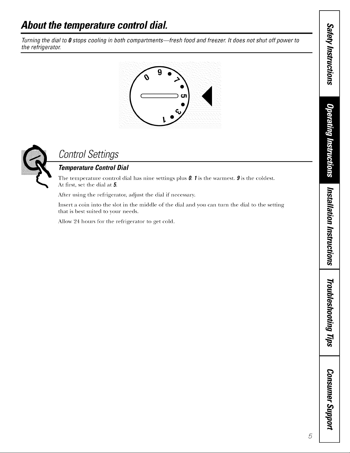
Aboutthe temperaturecontroldial
Turning the dial to 0 stops cooling in both compartments--fresh food and freezer. It does not shut off power to
the refrigerator.
ControlSettings
Temperature Control Dial
The temperature control dial has nine settings plus 0. I is the warmest. 9 is the coldest.
At first, set the dial at 5.
After using the refligerato_, adjust the dial if necessary.
Insert a coin into the slot in the middle of the dial and you can mrn the dial to the setting
that is best suited to your needs.
Allow 24 hours for the refligerator to get cold.
5
Aboutthefresh foodcompartmentshelves.
Shelf supports at various levels allow you to custom-space your shelves. Not all features are on all models.
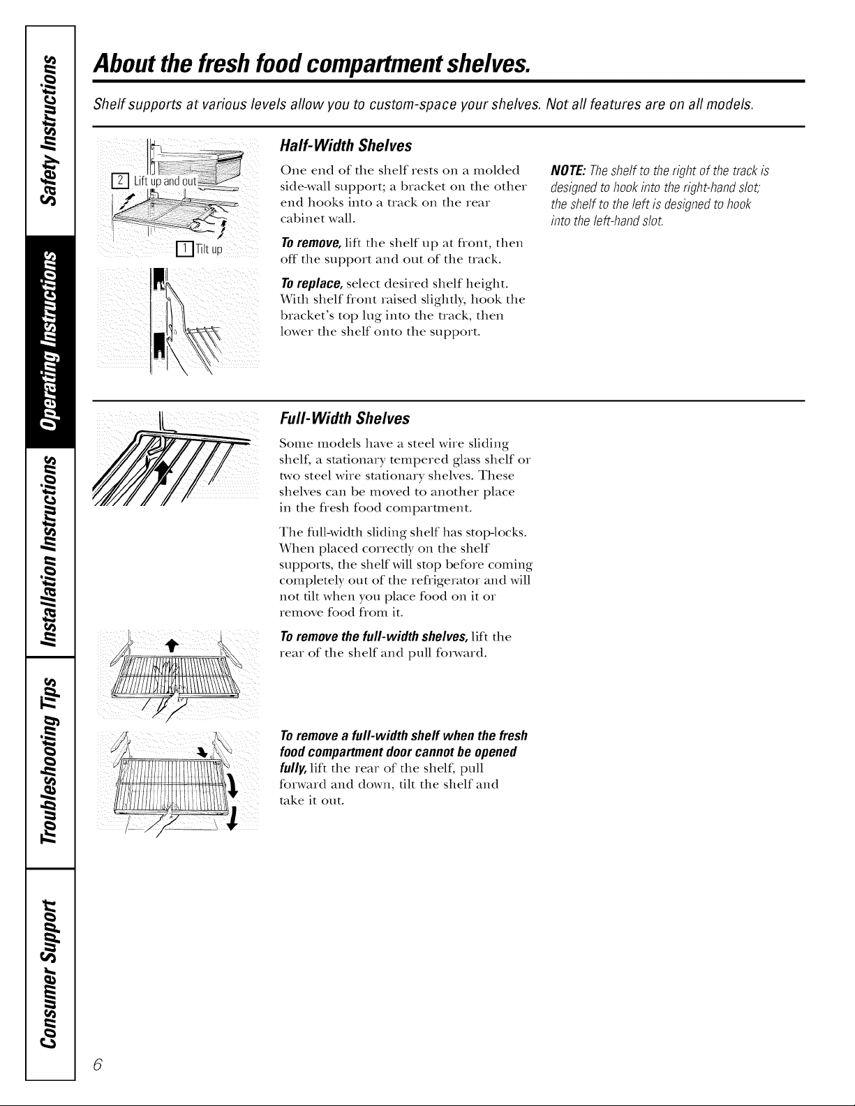
Half- Width Shelves
Liftupand
ITJTiltup
One end of the shelf rests on a molded
side-wall support; a bracket on the other
end hooks into a track on the rear
cabinet wall.
To remove, lift the shelf up at flont, then
off the support and out of the track.
To replace, select desired shelf height.
With shelf flont raised slightly, hook the
bracket's top lug into the track, then
lower the shelf onto the support.
Full-Width Shelves
Some models have a steel wire sliding
shelf, a stationary tempered glass shelf or
two steel wire stationary shelves. These
shelves can be moved to another place
in the flesh food comparunent.
NOTE:Theshelfto therightof thetrackis
designedtohookinto theright-handslot,
theshelf tothe left is designedtohook
into theleft-handslot.
The flfll-width sliding shelf has stop-locks.
When placed correctly on the shelf
supports, the shelf will stop before coming
completely out of the refligerator and will
not flit when you place food on it or
remove food flom it.
Toremovethefull-width shelves,lift the
rear of the shelf and pull forward.
Toremovea full-width shelf whenthefresh
foodcompartmentdoorcannotbeopened
fully, lift the rear of the shelf, pull
forward and down, tilt the shelf and
take it otlt.
6
About the freezer compartment shelves.
Some models have an ice-tray shelf and some have a full-width step shelf.
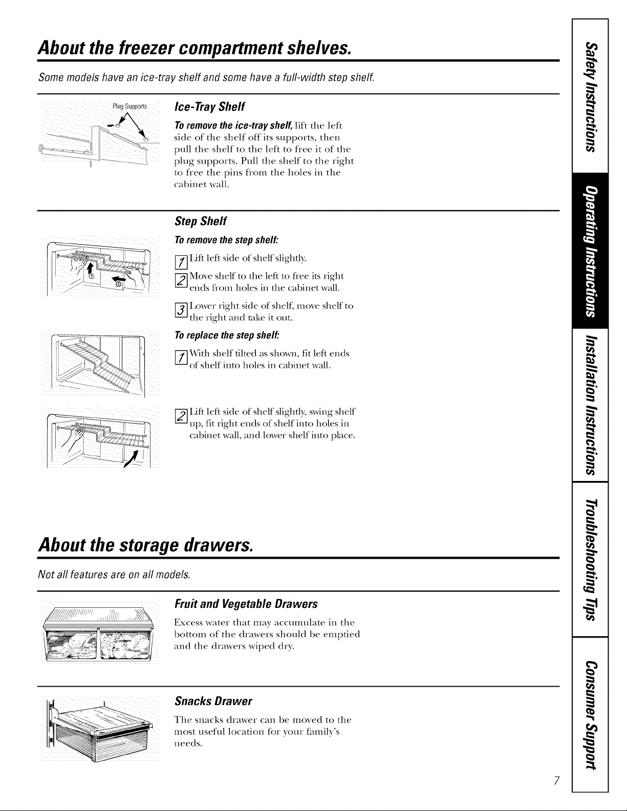
Ice- Tray Shelf
Toremovetheice-tray shelf,lift the left
side of the shelf off its supports, then
pull the shelf to the left to flee it of the
plug supports. Pull the shelf to the right
to flee the pins flom the holes in the
cabinet wall.
Step Shelf
Toremovethestep shelf"
[--7]Lift left side of shelf slightb:
[_-]Move shelf to the left to flee its right
ends flom holes in the cabinet wall.
V_I,ower right side of shelf, move shelf to
the right and rake it out.
Toreplacethe step shelf"
[--_With shelf tilted as shown, fit left ends
of shelf into holes in cabinet wall.
[_--]I,ift left side of shelf slightly, swing shelf
up, fit right ends of shelf into holes in
cabinet wall, and lower shelf into place.
About the storage drawers.
Not all features are on all models.
Fruit and Vegetable Drawers
Excess water that may accumulate in the
bottom of the drawers should be emptied
and the drawers wiped dry.
Snacks Drawer
The snacks drawer can be moved to the
most useflfl location for your family's
needs.
7

About storage drawer and cover removal.
Not all features are on all models.
Drawer and Cover Removal
Drawers can be removed easily by grasping
the sides and lifting up slightly while
pulling drawers past the stop location.
Full-Width Drawer with Plastic Cover
Toremove the cover, lift it off its supports,
[)tall it forward, tilt it and rake it out.
Twin Drawers with Glass Cover
Toremove:
V-_Remove the drawers.
[-_-]Reach in, push the fiont of glass
cover up, and at the same time,
pull it forward as far as it will come.
Tilt it and rake it out. Avoid cleaning the
cold glass cover with hot water because
the extreme temperature difference may
cause it to break.
V_]Remove the drawer flame. (Always
remove the glass cover before you
rake out the drawer flame.)
I,ifl the flame off the supports at each
side and back, pull it forward, tilt it and
take it out.
Toreplace:
V-_Lower the frame until it rests on the
supports at each side and back.
[-2--]Replace the glass cover, pushing its
rear edge firmly into the rear flame
channel and gently lowering the flont
into place.
[-_]Replace the drawers.
8
About the automatic icemaker.
A newly-installed refrigerator may take 12to 24 hours to begin making ice.
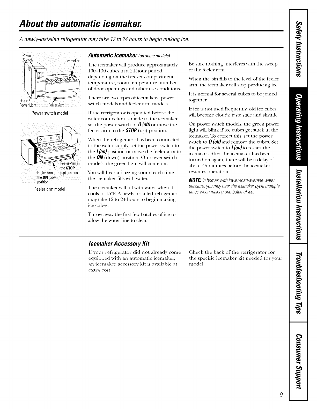
Switch Icemaker
Green
PowerLight lerArm
Powerswitch model
FeelerArmin
theSTOP
FeelerArmin (up)position
theON (down)
position
Feelerarm model
Automatic Icemaker (onsomemodels)
The icemaker will produce approximately
100-130 cubes in a 24-hour period,
depending on the fleezer comparunent
tempe_ture, room temperature, number
of door openings and other use conditions.
There are two types of icemakers: power
switch models and feeler arm models.
If die refligeiator is ope_v_md before die
wamr connection is made to die icemakei,
set the power switch m 0 (off)or move the
feeler arm m the STOP(up) position.
When file reflige_v_tor has been connecmd
m the wamr supply, set the power switch m
the I (0/1)position or move the feeler arm to
the ON (down) position. On power switch
models, file g_een light will come on.
You will hear a buzzing sound each time
the icemaker fills with water.
The icemaker Mll fill wifll water when it
cools m 15°E A newlyqnstalled refligeramr
may take 12 m 24 hours m begin making
ice cubes.
Be sure nothing interferes with the sweep
of the feeler arm.
When the bin fills to the level of the feeler
arm, the icemaker will stop producing ice.
It is normal for seve_vd cubes to be joined
togetheL
If ice is not used flequenfl); old ice cubes
will become cloudy, taste stole and shrink.
On power switch models, file gaeen power
light will blink if ice cubes get snack in the
icemake_. To correct this, set the power
switch m 0 (off)and remove the cubes. Set
the power switch m I (on)m restart the
icemake_. Afker the icemaker h_tsbeen
turned on again, there will be a delay of
about 45 minums before the icemaker
resumes ope_v_fion.
NOTE:Inhomeswith/ower-than-averagewater
pressure,youmayheartheicemakercyc/emu/tip/e
timeswhenmakingonebatchofice.
Throw away the first few batches of ice to
allow the water line to clea_.
Icemaker Accessory Kit
If your refrigerator did not aheady come
equipped with an automatic icemakei,
an icemaker accessory kit is available at
extra cost.
Check the back of the refligerator for
the specific icemaker kit needed for your
model.
9
Care and cleaning of the refrigerator.
Cleaning the Outside
Thedoorhandlesandtrim (on some
models). Clean with a cloth dampened
with soapy wateL Dry with a soft cloth.
Keep the outside clean. Wipe with a clean
cloth lightly dampened Mtb kitchen
appliance wax or mild liquid dish
detergent. Dry and polish with a clean,
soft cloth.
Cleaning the Inside
Tohelpprevent odors,leave an open box
of baking soda in the flesh food and
freezer compartments.
Unplugtherefrigeratorbeforecleaning.
If tiffs is not practical, wring excess
moisutre out of sponge or cloth when
cleaning around switches, lights or
controls.
Donot wipetherefrigeratorwitha soileddish
clothor wet towel Thesemayleavea residue
thatcanerodethepaint.Donotusescouring
pads,powderedcleaners,bleachorcleaners
containingbleachbecausetheseproductscan
scratchandweakenthepaint finish.
Avoidcleaningcoldglassshelves(onsome
models)with hot waterbecausetheextreme
temperaturedifferencemaycausethemto
break.Handleglassshelvescarefully.Bumping
temperedglasscancauseit toshatter.
Donot washany.plasticrefrigeratorparts in
thedishwasher.
.... _
ji: iii_I _ iii_
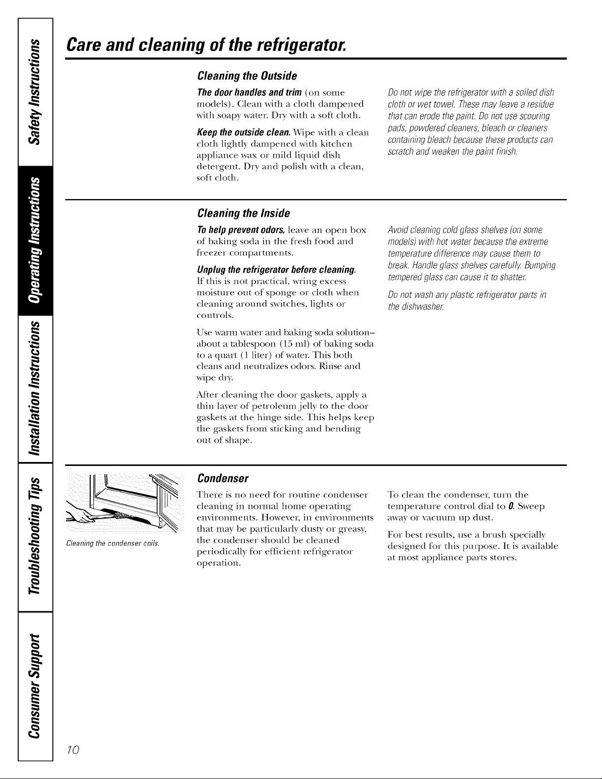
Cleaning the condenser coils.
Use warm water and baking soda solution-
about a tablespoon (15 ml) of baking soda
to a quart (1 limr) ofwamL This both
cleans and neumdizes odors. Rinse and
wipe d_y.
After cleaning the door gaskets, apply a
thin layer of peuoleumjelly to tim door
gaskets at the hinge side. This helps keep
the gaskets from sticking and bending
out of shape.
Condenser
There is no need for routine condenser
cleaning in normal home operating
environments. However, in environments
I
that may be particularly dusty or greasy,
the condenser should be cleaned
periodically for efficient refrigerator
operation.
To clean tim condenser; turn the
temperaune conuol dial to 0. Sweep
away or vacuum lap dust.
For best results, use a brush specially
designed for tiffs purpose. It is available
at most appliance parts stores.
7O
Behind the Refrigerator
Be careful when moving the refrigerator
away from the wall. All types of floor
coverings can be damaged, particularly
cushioned coverings and those with
embossed surfaces.
Turn the leveling legs at each flont corner
of the refligerator counterclockwise until
the rolleas support the refligerator. Pull the
refligeramr straight out and return it m
position by pushing it suaight in. Moving
the refligerator in a side direction may
result in damage to the floor covering or
refligeramL
Light Bulb Replacement
To replace a burned-out bulb, unplug
the refrigerator from its electrical outlet,
unscrew the bulb when cool and replace
it with an appliance bulb of the same or
lower wattage.
When pushing the refrigerator back, make sure
you don't roll over the power cord or icemaker
supply line (onsome models).
After rolling the refligerator back into
place, mrn the legs clockwise until the
legs again bear the weight of the
refligeratoL
Turningthecontrolto theOpositiondoesnot
removepowerto thelight circuit.
Preparing for Vacation
For long vacations or absences, remove
food and unplug the refligeratoL Move
the temperature control dial to the 0
position, and clean the interior with a
baking soda solution of one tablespoon
(15 ml) of baking soda to one quart
(1 liter) ofwateL I,eave the doors open.
Preparing to Move
Secure all loose items such as grille,
shelves and drawers by roping them
securely in place to prevent damage.
Set the icemaker power switch to the
0 (off) position or move the feeler arm to
the STOP (tap) position (depending on
model) and slmt off the water supply to
the refligeratoL
If the temperature can drop below
freezing, have a qualified servicer drain
the water supply system (on some
models) to prevent serious property
damage due to flooding.
Besuretherefrigeratorstaysin an upright
positionduringmoving.
11
Installation
Refrigerator
Instructions
Models 15, 16,17,18
Questions? Call 800.GE.CARES (800.432.2737)or visit o,_Website_,t"www.GEAppliances.com
In Canada, call 1.800.361.3400or Visitour Website at: www.geappliances.ca
BEFORE YOU BEGIN
Read these instructions completely and carefully.
• IMPORTANT - S},vethese
instructions for local inspector's use.
• IMPORTANT - Obse,ve
governing codes and ordinances.
CLEARANCES
Allow the following clearances for ease of installation,
proper air circulation and plumbing and electrical
COIlllectioIIS.
• Sides,/4 (19 ram)
• Top 1" (25 mm)
• Back 1" (25 ram)
• Note to Installer - Besure to leave these
instructions with the Gonsumer.
• Note to Consumer - Keep these insuuctions
for fl_ture reference.
• Sldll level - Installation of tiffs appliance requires
basic mechanical skills.
• Completion time - Refligerator Installation
15 minutes
Reversing the Door Swing
1 hour
• Proper installation is the responsibility of the
insmlleL
• Product failure due to improper installation is not
covered under the Warranty.
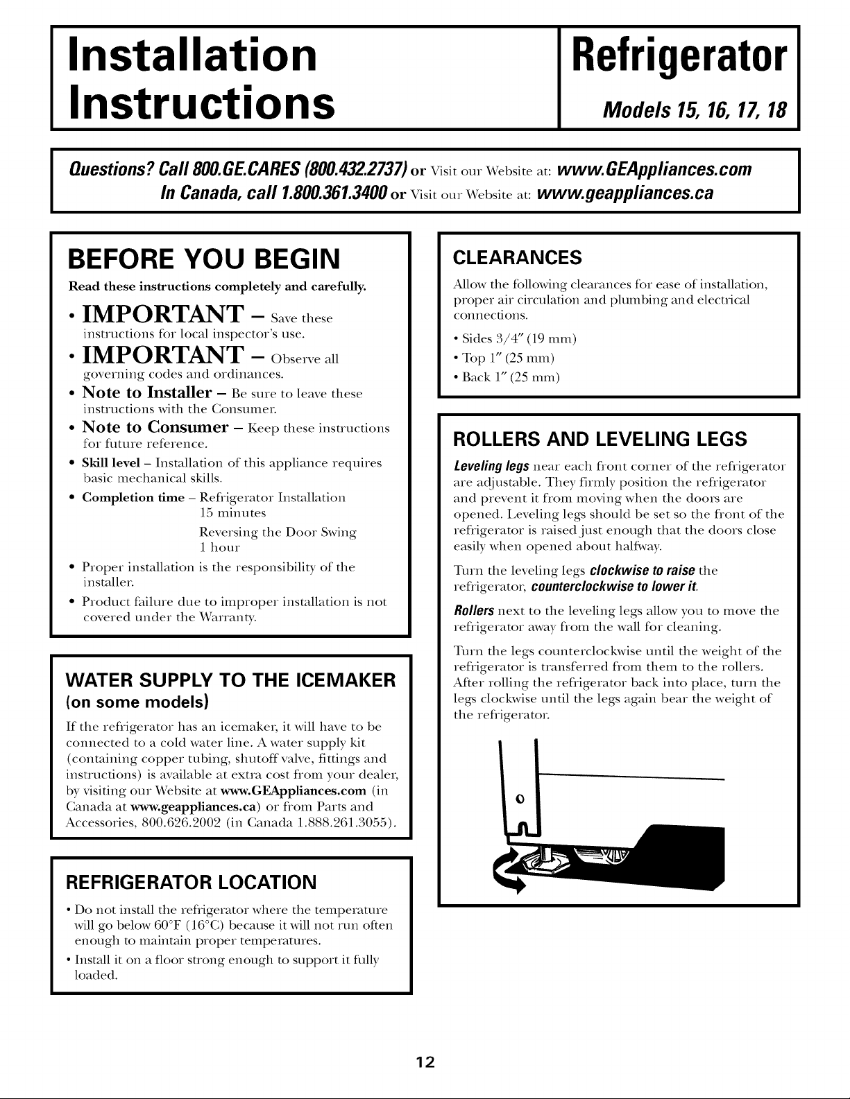
ROLLERS AND LEVELING LEGS
Leveling legs near each flont corner of the refligerator
are adjustable. They firmly position the refligerator
and prevent it flom moving when the doors are
opened. I,eveling legs should be set so the front of the
refligerator is raised just enough that the doors close
easily when opened about half,,ray.
Turn the leveling legs clockwise to raise the
refligerato_, counterclockwiseto lower it
Rollers next to the leveling legs allow you to move the
refligerator away flom the wall for cleaning.
WATER SUPPLY TO THE ICEMAKER
(on some models)
If the refligerator has an icemake_; it Mll have to be
connected to a cold water line. A water supply kit
(containing copper tubing, shutoff valve, fittings and
instruc6ons) is available at extra cost flom your dealer,
by visiting our Website at www.GEAppliances.com (in
Canada at www.geappliances.ca) or flom Parts and
Accessories, 800.626.2002 (in Canada 1.888.261.3055).
REFRIGERATOR LOCATION
• Do not instM1 the refligerator where the temperature
will go below 60°F (16°C) because it will not run often
enough m maintain proper temperatures.
• Install it on a floor suong enough to support it flail),
loaded.
Turn the legs counterclockwise until the weight of the
refiigerator is transferred fiom them to tim rollers.
After rolling the refiigerator back into place, mrn the
legs clockwise until the legs again bear the weight of
the refiigeratoL
12
Installation Instructions
B INSTALLING THE WATER LINE IONSOMEMODELS)
BEFORE YOU BEGIN
Recommended copper water supply kits are _(_'X8X2,
_(_2K8X3or _'X8X4, depending on the amount of
robing you need. Approved plastic water supply lines
are GE SmartConnect'" Refligerator Tubing
(X_qK08X10002, _(_2K08X10006, _(_2K08X10015 and
_i_XO8X10025).
When connecting your refligerator to a GE Reverse
Osmosis Water System, the only approved installation
is with a GE RVKit. For other reverse osmosis water
systems, follow the manufacturer's recommendations.
This water line installation is not warranted by the
refrigerator or icemaker manufitcturer. Follow these
instructions careflflly to minimize the risk of expensive
water damage.
Water hammer (water banging in the pipes) in house
plumbing can cause damage to refiigerator parts and
lead to water leakage or flooding. Call a qualified
plumber to correct water hammer before installing
the water supply line to the refiigerator.
To prevent burns and product damage, do not hook
up the water line to the hot water line.
If you use your refligerator before connecting the
water line, make sure the icemaker power switch is
in the 0 (off) position (on power switch models) or
the feeler arm is in the STOP (tap) position (on feeler
arm models).
WHAT YOU WILL NEED
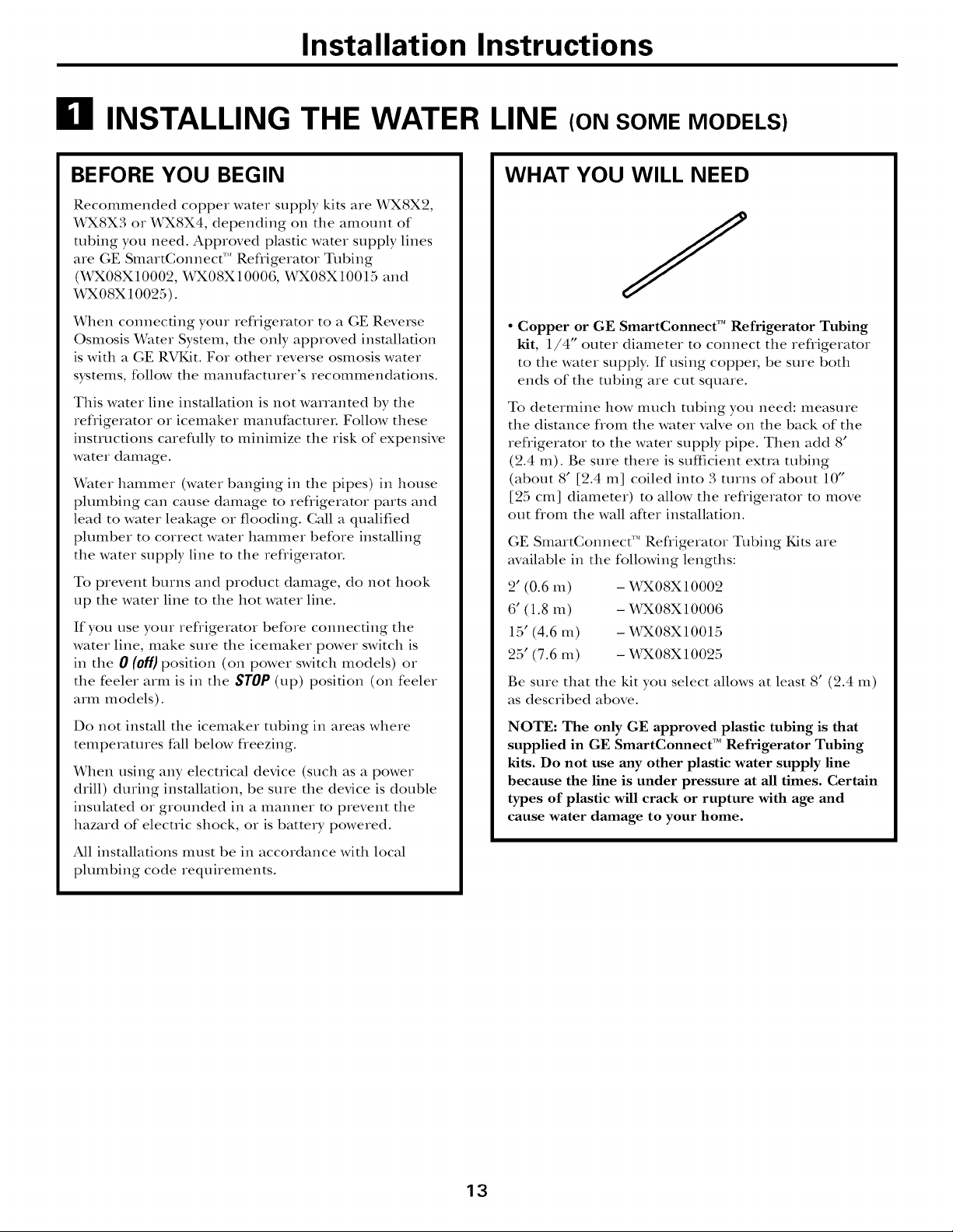
• Copper or GE SmartConnect TM Refrigerator Tubing
kit, 1/4" outer diameter to connect the refligerator
to the water supply. If using coppe_, be sure both
ends of the tubing are cut square.
To determine how much tubing you need: measure
the distance flom the water valve on the back of the
refligerator to the water supply pipe. Then add 8'
(2.4 m). Be sure there is sufficient extra tubing
(about 8' [2.4 m] coiled into 3 turns of about 10"
[25 cm] diameter) to allow the refligerator to move
out flom the wall after installation.
GE SmartConnect"* Refligerator Tubing Kits are
available in the following lengths:
2' (0.6 m) - _2K08X10002
6' (1.8 m) -X42K08X10006
15' (4.6 m) - _2KO8XlO015
25' (7.6 m) - _2K08X10025
Be sure that the kit you select allows at least 8' (2.4 m)
as described above.
Do not install the icemaker tubing in areas where
temperatures fall below fleezing.
When using any electrical device (such as a power
drill) during installation, be sure the device is double
insulated or grounded in a manner to prevent the
hazard of electric shock, or is battm y powered.
All installations must be in accordance with local
plumbing code requirements.
NOTE: The only GE approved plastic tubing is that
supplied in GE SmartConnect TM Refrigerator Tubing
kits. Do not use any other plastic water supply line
because the line is under pressure at all times. Certain
types of plastic will crack or rupture with age and
cause water damage to your home.
13
Installation Instructions
ill INSTALLING THE WATER LINE (CONT.)
WHAT YOU WILL NEED (CONT.)
• A GE water supply kit (containing ulbing, slmtoff
valve and fittings listed below) is available at extra
cost flom your dealer or flom Parts and Accessories,
800.626.2002.
• A cold water supply. The water pressure must be
between 20 and 120 p.s.i. (11.4-8.1 bar).
• Power drill.
• 1/2" or adjustable wrench.
• Straight and Phillips blade screwdriver.
• Two 1/4" outer diameter compression nuts and
2 ferrules (sleeves)--to connect the copper tubing
to tim stmtoff valve and tim refligerator water vaNe.
OR
• If you are using a GE SmartConnect'* Refligerator
Tubing kit, tim necessary fittings are preassembled
to the tubing.
Install the stmtoff valve on the nearest flequently used
drinking water line.
IT] SHUT OFF THE MAIN WATER
SUPPLY
Turn on tim nearest faucet long enough to clear
the line ofwateL
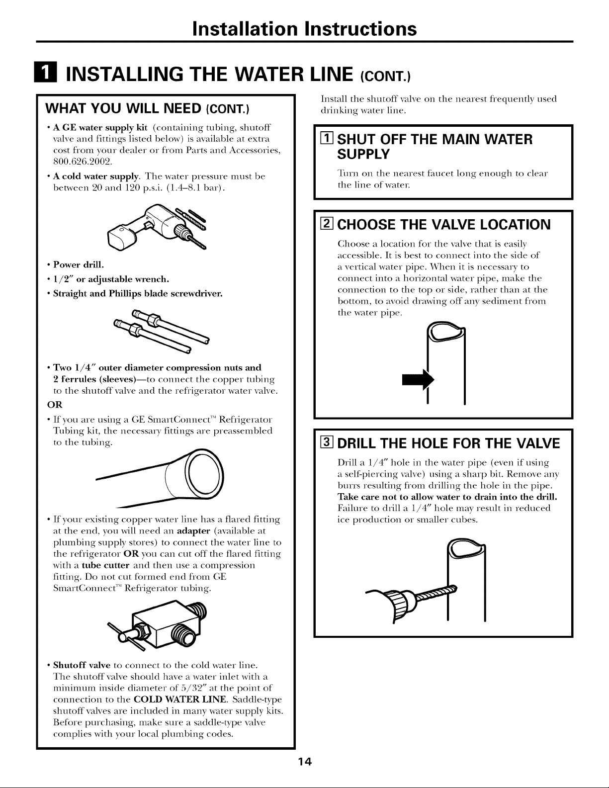
CHOOSE THE VALVE LOCATION
Choose a location for tim valve that is easily
accessible. It is best to connect into the side of
a vertical water pipe. When it is necessa_ T to
connect into a horizontal water pipe, make the
connection to the top or side, rather than at tim
bottom, to avoid drawing off"any sediment flom
the water pipe.
I_ DRILL THE HOLE FOR THE VALVE
• If your existing copper water line has a flared fitting
at the end, you will need an adapter (available at
plumbing supply stores) to connect the water line to
the refligerator OR you can cut off" the flared fitting
with a tube cutter and then use a compression
fitting. Do not cut formed end flom GE
SmartConnect"* Refiigerator robing.
• Shutoff valve to connect to the cold water line.
The shutoff valve should have a water inlet with a
mininmm inside diameter of 5/32" at the point of
connection to the COLD WATER LINE. Saddle-type
shutoff vanes are included in many water supply kits.
Before purchasing, make sure a saddle-type valve
complies with your local plumbing codes.
Drill a 1/4" hole in the water pipe (even if using
a self-piercing valve) using a sharp bit. Remove any
burrs resulting flom drilling tim hole in tim pipe.
Take care not to allow water to drain into the drill.
Failure to drill a 1/4" hole may result in reduced
ice production or smaller cubes.
14

Installation Instructions
I_ FASTEN THE SHUTOFF VALVE
Fasten the shutoff valve to the cold water pipe with
the pipe clamp.
PipeClamp_'x_,
Saddle-TypeJ qerticalCold
ShutoffValve WaterPipe
NOTE: Commonwealth of Massachusetts Plumbing
Codes 248CMR shall be adhered to. Saddle valves
are illegal and use is not permitted in Massachusetts.
Consult with your licensed plumbeL
[] TIGHTEN THE PIPE CLAMP
Tighten the clamp screws until the sealing washer
begins to swell.
NOTE: Do not overtighten or you may crush the
tubing.
Pipe Clamp
/_lnlet End
Washer
[] CONNECT THE TUBING
TO THE VALVE
Place the compression nut and ferrule (sleeve)
for copper tubing onto the end of the tubing and
connect it to the shutoff valve.
Make sure the tubing is flail), inserted into the
valve. Tighten the compression nut securely.
For plastic robing flom a GE SmartConnecff'*
Refligerator Tubing kit, insert the molded end
of the tubing into the shutoff valve and tighten
compression nut until it is hand tight, then tighten
one additional turn with a wrench. Overfightening
may cause leaks.
Saddle-Type
ShutoffValve
PackingNut--
OutletValve._ _ Ferrule(sleeve)
NOTE: Commonwealth of Massachusetts Plumbing
Codes 248CMR shall be adhered to. Saddle vanes
are illegal and use is not permitted in Massachusetts.
Consult with your licensed plumber.
Nut
SmartConnect_
Tubing
_ression
Clamp Screw_
?
ROUTE THE TUBING
Route the tubing between the cold water line and
the reffigeratoL
Rotate the tubing through a hole drilled in the wall
or floor (behind the refligerator or adjacent base
cabinet) as close to the wall as possible.
NOTE: Be sure there is sufficient extra tubing
(about 8 feet [244 cm] coiled into 3 turns of about
10" [25 cm] diameter) to allow the refligerator to
move out from the wall after installation.
I-8-]FLUSH OUT THE TUBING
Turn the main water supply on and flush out the
tubing until the water is clear.
Shut the water off at the water valve after about
one quart (1 liter) of water has been flushed
through the tubing.
15
Installation Instructions
B INSTALLING THE WATER LINE (CONT.)
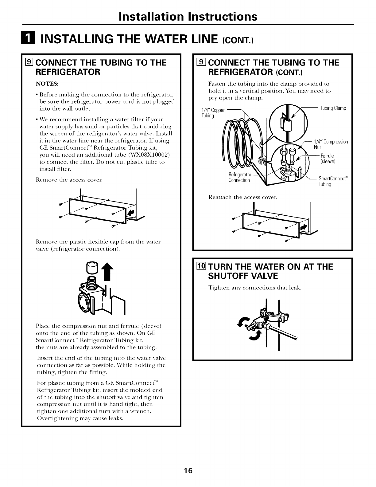
I_ CONNECT THE TUBING TO THE
REFRIGERATOR
NOTES:
• Before making tile connection to tile refligerator,
be sure tile refligerator power cord is not plugged
into tile wall outlet.
• X_rerecommend installing a water filter if your
water supply has sand or particles that could clog
tile screen of tile refligerator's water valve. Install
it in tile water line near tile refligerator. If using
GE SmartConnect'" Refligerator Tubing kit,
you will need an additional robe (X_K08X10002)
to connect tile filteL Do not cut plastic tube to
install filteL
Remove tile access coveL
[] CONNECT THE TUBING TO THE
REFRIGERATOR (CONT.)
Fasten tile tubing into tile clamp provided to
hold it in a vertical position. You may need to
pry open tile clamp.
1/4" Copper __ TubingClamp
Tubing
1/4" Compression
Nut
Ferrule
(sleeve)
Refrigerator
Connection SmartConnecU
Reattach tile access coveL
Tubing
Remove tile plastic flexible cap flom tile water
valve (refligerator connection).
©
Place tile compression nut and ferrule (sleeve)
onto tile end of tile tubing as shown. On GE
SmartGonnect"* Refligerator Tubing kit,
tile nuts are aheady assembled to tile robing.
Insert tile end of tile tubing into tile water valve
connection as far as possible. While holding tile
tubing, tighten tile fitting.
For plastic tubing flom a GE SmartGonnect"*
Refligerator Tubing kit, insert tile molded end
of tile tubing into tile shutoff valve and tighten
compression nut until it is hand tight, then
tighten one additional mrn with a wrench.
Overtightening may cause leaks.
I_ TURN THE WATER ON AT THE
SHUTOFF VALVE
Tighten any connections that leak.
16
Installation Instructions
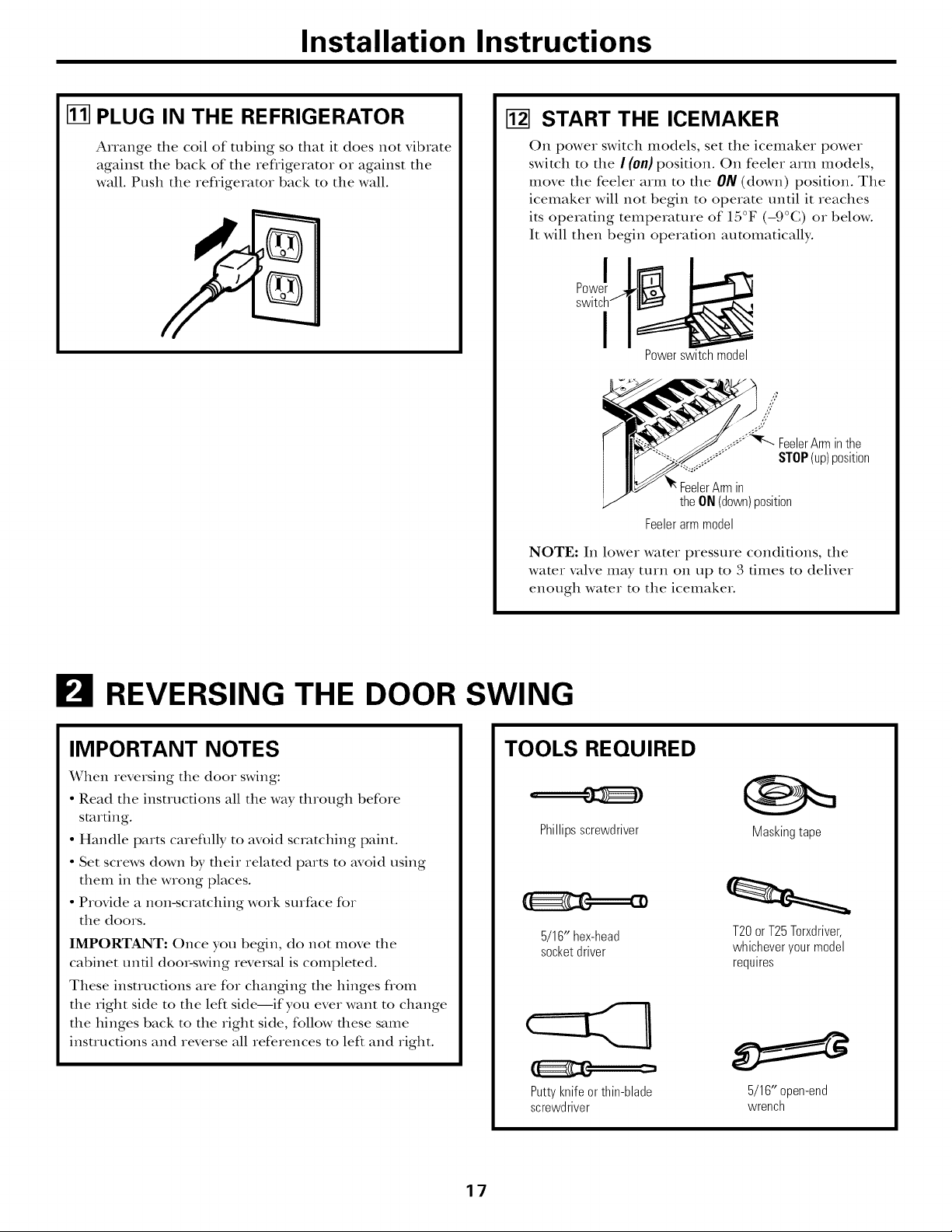
I_] PLUG IN THE REFRIGERATOR
Arrange the coil of tubing so that it does not vibrate
against the back of the refligerator or against the
wall. Push the refligerator back to the wall.
[] START THE ICEMAKER
On power switch models, set the icemaker power
switch to the / (0n) position. On feeler arm models,
move the feeler arm to the ON(down) position. The
icemaker will not begin to operate until it reaches
its operating temperature of 15°F (-9°C) or below.
It will then begin operation automatically.
I
Powerswitch model
,7
//
,'Y
//
.##;"_r--...FeelerArminthe
..... STOP(up)position
in
theON(down)position
Feelerarmmodel
NOTE: In lower water pressure conditions, the
water valve may tuin on up to 3 times to deliver
enough water to the icemaker.
REVERSING THE DOOR SWING
IMPORTANT NOTES
When reversing the door swing:
• Read the instructions all the way through before
starting.
• Handle parts careflflly to avoid scratching paint.
• Set screws down by their related parts to avoid using
them in the wrong places.
• Provide a non-scratching work surface for
the doors.
IMPORTANT: Once you begin, do not move the
cabinet until door-swing reversal is completed.
These insmlcfions are for changing the hinges flom
the right side to the left side--if you ever want to change
the hinges back to the right side, follow these same
insu-ucdons and reverse all references to left and right.
TOOLS REQUIRED
Phillipsscrewdriver
5/16"hex-head
socketdriver
Puttyknifeorthin-blade
screwdriver
Masking tape
T20or T25Torxdriver,
whicheveryourmodel
requires
5/16" open-end
wrench
17
Installation Instructions
B REVERSING THE DOOR SWING (CONT.)
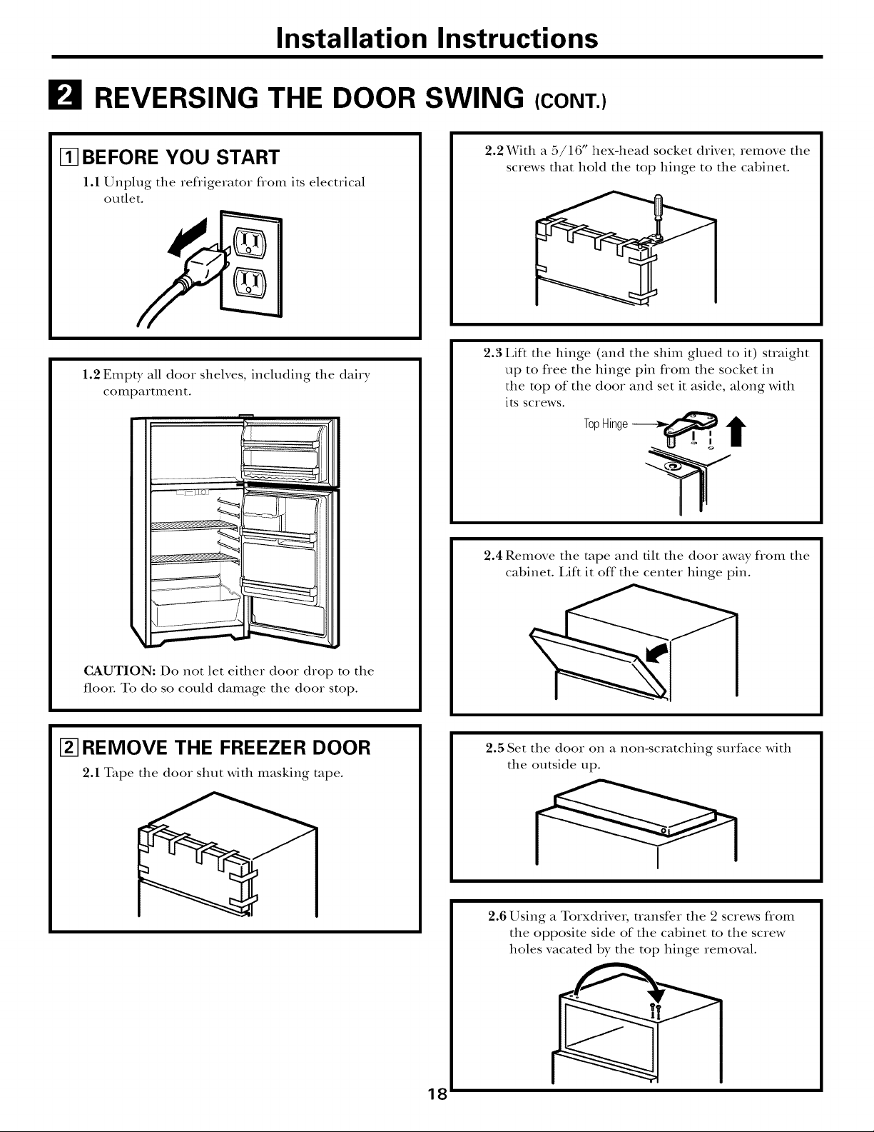
Ill BEFORE YOU START
1.1 Unplug the refrigerator from its electrical
outlet.
1.2 Empty all door shelves, including the dairy
compartment.
2.2 With a 5/16" hex-head socket drive_, remove the
screws that hold the top hinge to the cabinet.
2.3 I,iff the hinge (and the shim glued to it) suaight
up to flee the hinge pin flom the socket in
the top of the door and set it aside, along with
its screws.
TopHinge-_a___
2.4 Remove the rope and tilt the door away flom the
cabinet. I,ift it off"the center hinge pin.
CAUTION: Do not let either door drop to the
flooL To do so could damage the door stop.
[] REMOVE THE FREEZER DOOR
2.1 Tape the door shut with masking rope.
2.5 Set the door on a non-scratching surface with
the outside up.
2.6 Using a Torxdrive,, transfer the 2 screws flom
the opposite side of the cabinet to the screw
holes vacated by the top hinge removal.
18
Installation Instructions
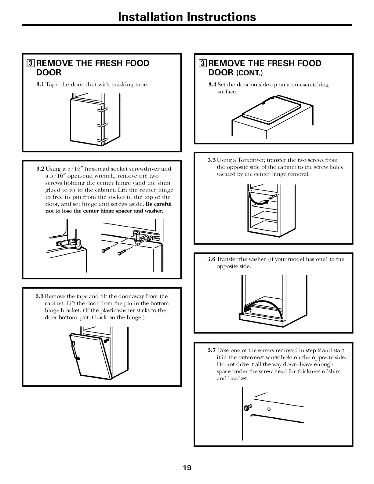
I_ REMOVE THE FRESH FOOD
DOOR
3.1 Tape the door shut with masking rope.
3.2 Using a 5/16" hex-head socket screwdriver and
a 5/16" open-end wrench, remove the two
screws holding the center binge (and the shim
glued to it) to the cabinet. I,ift the center hinge
to flee its pin flom the socket in the top of the
door, and set hinge and screws aside. Be careful
not to lose the center hinge spacer and washer.
[_] REMOVE THE FRESH FOOD
DOOR (CONT.)
3.4 Set file door outside-,up on a non-scratching
StlIface.
3.5 Using a Torxdrive_; uansfer the two screws flom
the opposim side of the cabinet to the screw holes
vacated by the cenmr hinge removal.
3.3 Remove dm tape and flit die door away flom file
cabinet. I,ift die door flom file pin in die bottom
hinge bracket. (If file plastic washer sticks to the
door bottom, put it back on file hinge.)
/
3.6 Transfer file washer (if your model has one) m the
opposite side.
3.7 Take one of file screws removed in stop 2 and start
it in the oumrmost screw hole on the opposite side.
Do not drNe it all the way down-le_,e enough
space under the screw head for thickness of shim
and bracket.
0
19
Installation Instructions
B REVERSING THE DOOR SWING (CONT.)
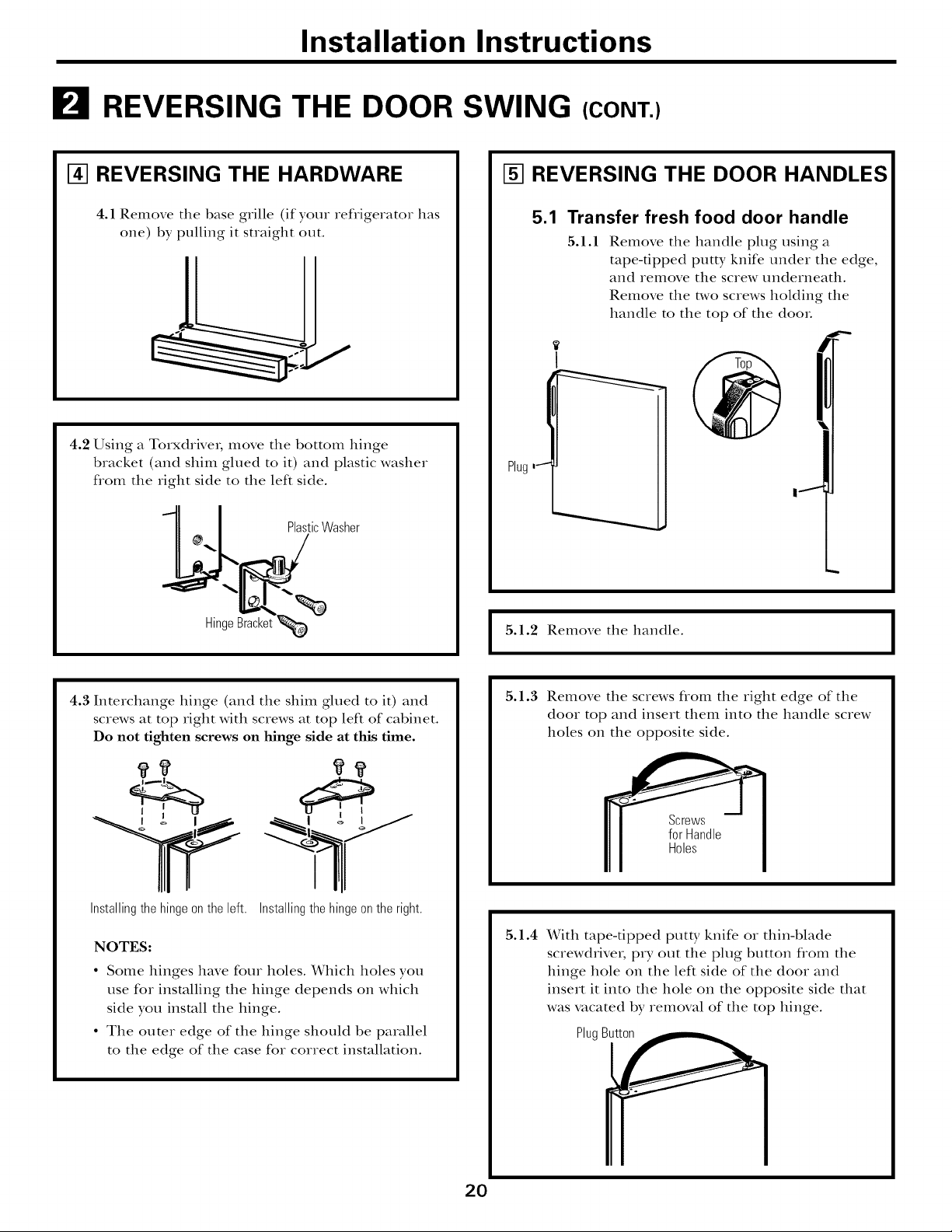
141REVERSING THE HARDWARE
4.1 Remove the base grille (if your refrigerator has
one) by pulling it straight out.
4.2 Using a Torxdrive_, move the bottom hinge
bracket (and shim glued to it) and plastic washer
flom the right side to the left side.
11 I PlasticWasher
[] REVERSING THE DOOR HANDLES
5.1 Transfer fresh food door handle
5.1.1
Remove the handle plug using a
tape-tipped putty knife under the edge,
and remove the screw underneath.
Remove the two screws holding the
handle to the top of the dooL
!
Plug,_
4.3 Interchange hinge (and the shim glued to it) and
screws at top right with screws at top left of cabinet.
Do not tighten screws on hinge side at this time.
Installingthe hingeonthe left. Installingthehinge onthe right.
NOTES:
• Some hinges have four holes. Which holes you
use for installing the hinge depends on which
side you install the hinge.
• The outer edge of the hinge should be parallel
to the edge of the case for correct installation.
5.1.2 Remove the handle.
I
5.1.3
Remove the screws flom the right edge of the
door top and insert them into the handle screw
holes on the opposite side.
5.1.4 With tape-tipped putty knife or thin-blade
screwdrivei; pry out the plug button flom the
hinge hole on the left side of the door and
insert it into the hole on the opposite side that
was vacated by removal of the top hinge.
I
2O
PlugBu_
Installation Instructions
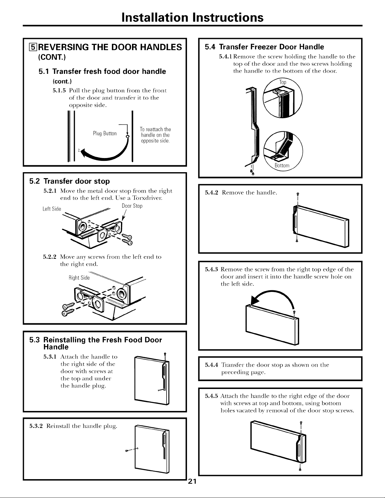
[]REVERSING THE DOOR HANDLES
(CONT.)
5.1 Transfer fresh food door handle
(cont.)
5.1.5 Pull the plug button from the front
of the door and transfer it to the
opposite side.
PlugButton
5.2
Transfer door stop
5.2.1 Move the metal door stop from the right
end to the left end. Use a TorxdriveL
LeftSide
Toreattachthe
handleonthe
oppositeside.
DoorStop
5.4 Transfer Freezer Door Handle
5.4.1 Remove the screw holding the handle to the
top of the door and the two screws holding
the handle to the bottom of the dooL
5.4.2 Remove the handle.
5.2.2 Move any screws from the left end to
the right end.
Right_iSide_
5.3
Reinstalling the Fresh Food Door
Handle
5.3.1 Attach the handle to
the right side of the
door with screws at
the top and under
the handle plug.
5.3.2 Reinstall the handle plug.
5.4.3 Remove the screw flom the right top edge of the
door and insert it into the handle screw hole on
the left side.
5.4.4 Transfer the door stop as shown on the
I
preceding page.
5.4.5 Attach the handle to the right edge of the door
with screws at top and bottom, using bottom
holes vacated by remowd of the door stop screws.
I
21
Installation Instructions
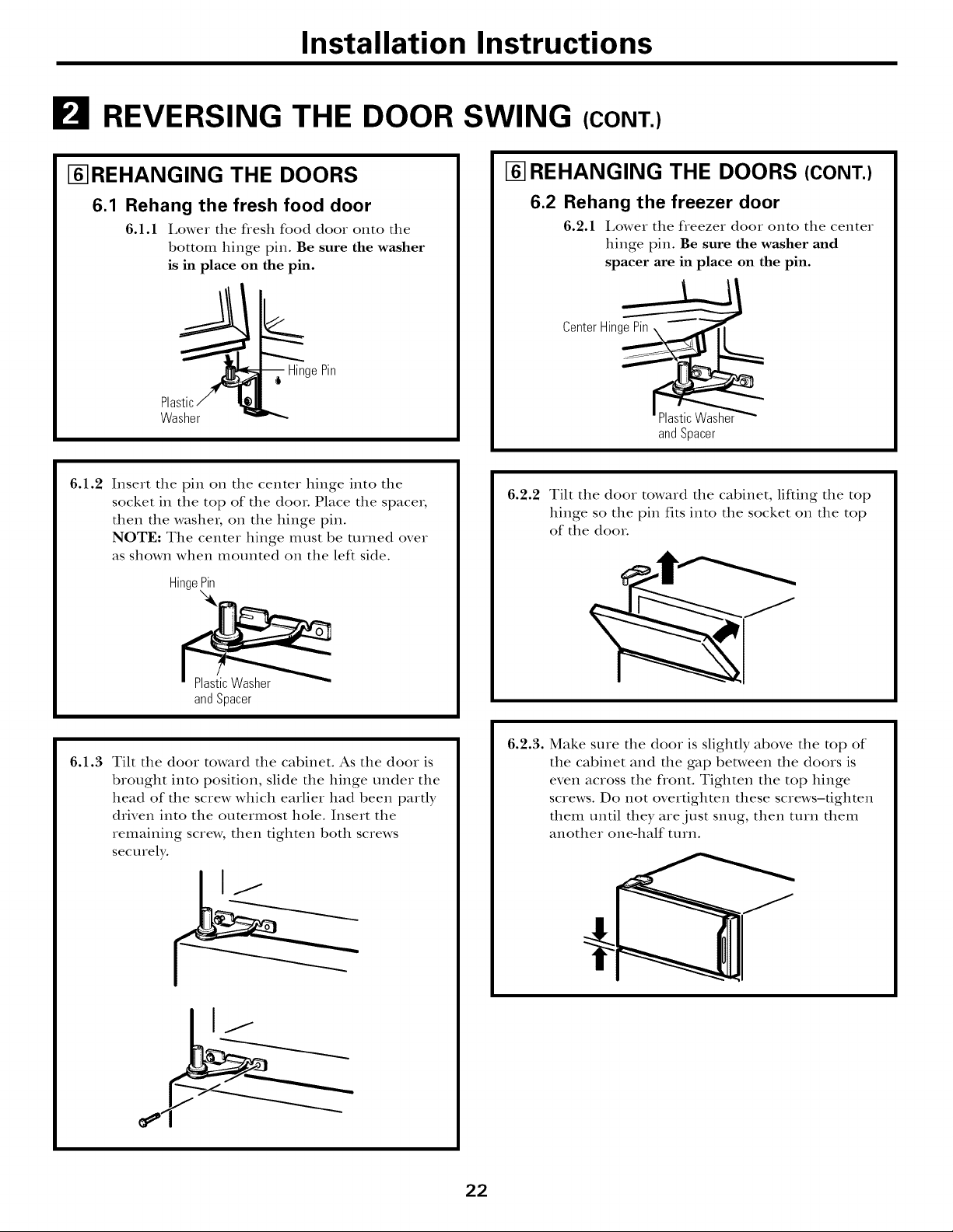
REVERSING THE DOOR SWING (CONT.)
I-_REHANGING THE DOORS
6.1 Rehang the fresh food door
6.1.1 Lower tim fresh food door onto tim
bottom binge pin. Be sure the washer
is in place on the pin.
HingePin
Washer
6.1.2 Insert the pin on tim center hinge into tile
socket in tile top of tile dooL Place tile space_,
then tile washer, on tile hinge pin.
NOTE: Tile center hinge IIl/lst be turned over
as shown when mounted on tile left side.
Hinge_
I-_REHANGING THE DOORS (CONT.)
6.2 Rehang the freezer door
6.2.1 Lower tim freezer door onto tim center
hinge pin. Be sure the washer and
spacer are in place on the pin.
andSpacer
6.2.2 Tilt tile door toward tile cabinet, lifting tile top
hinge so tile pin fits into tile socket on tile top
of tile dooL
andSpacer
6.1.3 Tilt tile door toward tile cabinet. As tile door is
brought into position, slide tile hinge under tile
head of the screw which earlier had been pardy
driven into tile outermost hole. Insert tile
remaining screw, then tighten both screws
securely.
6.2.3. Make sure tile door is slighdy above tile top of
tile cabinet and tile gap between tile doors is
even across tile flont. Tighten tile top hinge
screws. Do not overtighten these screws-tighten
them until they are just snug, then t/lIn them
another one-half t/lin.
22
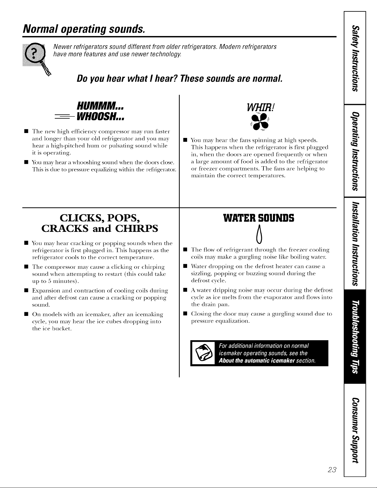
Normal operating sounds.
Newer refrigerators sound different from older refrigerators. Modern refrigerators
have more features and use newer technology.
Do you hear what I hear? These sounds are normal.
HUMMM...
-- WHOOSH...
• The new high efficiency compressor may run faster
and longer than your old refligerator and you may
hear a high-pitched hum or pulsating sound while
it is operating.
• You may hear a whooshing sound when file doors close.
This is due to pressure equalizing wiflfin file refrigeratoi.
CLICKS, POPS,
CRACKS and CHIRPS
• You may hear cracking or popping sounds when the
refiigerator is first plugged in. This happens as the
refligerator cools to the correct temperature.
• The compressor may cause a clicking oi chirping
sound when attempting to restart (this could take
up to 5 minutes).
• Expansion and conuacfion of cooling coils during
and after defiost can cause a cracking oi popping
sotlnd.
On models with an icemakei, after an icemaking
cycle, you may hear the ice cubes dropping into
the ice bucket.
WHIB/
• You may hear the fans spinning at high speeds.
This happens when the refligerator is first plugged
in, when the doors are opened flequenfly oi when
a large amount of food is added to the refligerator
oi fleezer compartments. The fans are helping to
maintain the correct temperatures.
WATERSOUNDS
6
• The flow of refligerant through the fleezer cooling
coils may make a gurgling noise like boiling wateL
• X_rater dropping on the deflost heater can cause a
sizzling, popping oi buzzing sound during the
deflost cycle.
• A water dripping noise may occur during the deflost
cycle as ice melts flom the evaporator and flows into
the drain pan.
• Closing the door m W cause a gtngling sound due to
pressure equalization.
23
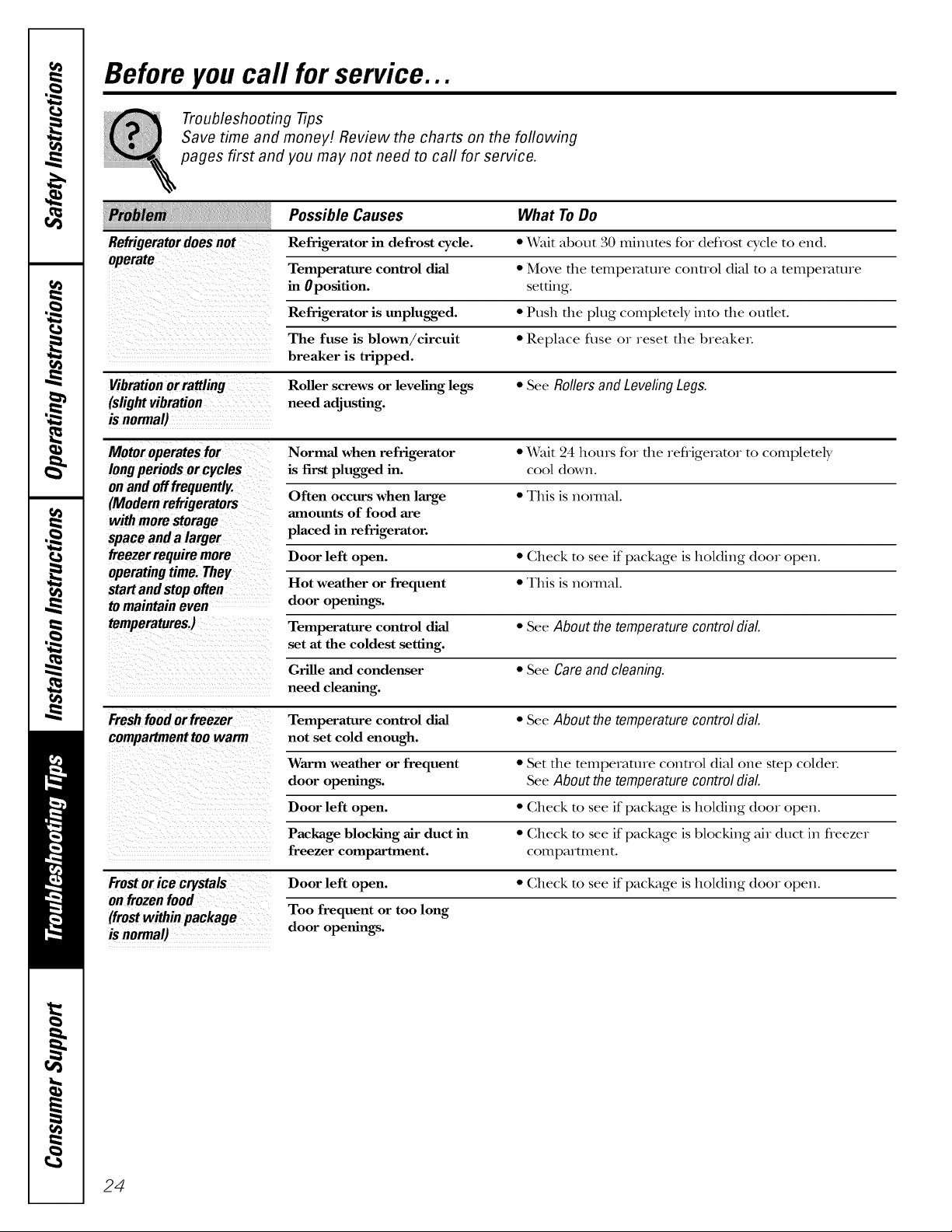
Before you call for service...
Troubleshooting Tips
Save time and money! Review the charts on the foflowing
pages first and you may not need to call for service.
Possible Causes What ToDo
Refrigerator in defrost cycle. * \Vait about 30 minutes for defrost cycle to end.
Temperature control dial • Move the teInpe]_mue control dial to a temperature
in 0position, setting.
Refrigerator is tmplugged. • Push the plug completely into the outlet.
The fuse is blown/circuit • Replace fl_se or reset the breakm.
breaker is tripped.
Vibration or rattling Roller screws or leveling legs • See Rollers and Leveling Legs.
(slight vibration need adjusting.
is normal)
Motor operates for Normal when refrigerator • \Vait 24 hours for the refligerator to completely
long periods or cycles is first plugged in. cool down.
on and offfrequently.
(Modern refrigerators Often occurs when large • This is hernial.
with morn storage amounts of food are
space and a larger placed in refrigerator.
freezer require more Door left open. • Gheck to see if package is holding (loot open.
operating time. They
start and stop often Hot weather or frequent • This is nomaal.
tomaintain even door openings.
temperatures4 Temperature control dial • See About the temperature control dial.
set at the coldest setting.
Grille and condenser • See Careandcleaning.
need cleaning.
Freshfood orfreezer Temperature control dial * See About the temperature control dial.
compartment too warm not set cold enough.
Warm weather or frequent • Set the temperature control dial one step col(let.
door openings. See About the temperature control dial.
Door left open. * Gheck to see if package is holding (loot open.
Package blocldng air duct in • Gheck to see if package is blocking air duct in fleezer
freezer compartment, compartment.
Frostor ice crystals Door left open. • Gheck to see if package is holding (loot open.
on frozen food
(frostwithinpackage
isnormal)
Too frequent or too long
door openings.
24
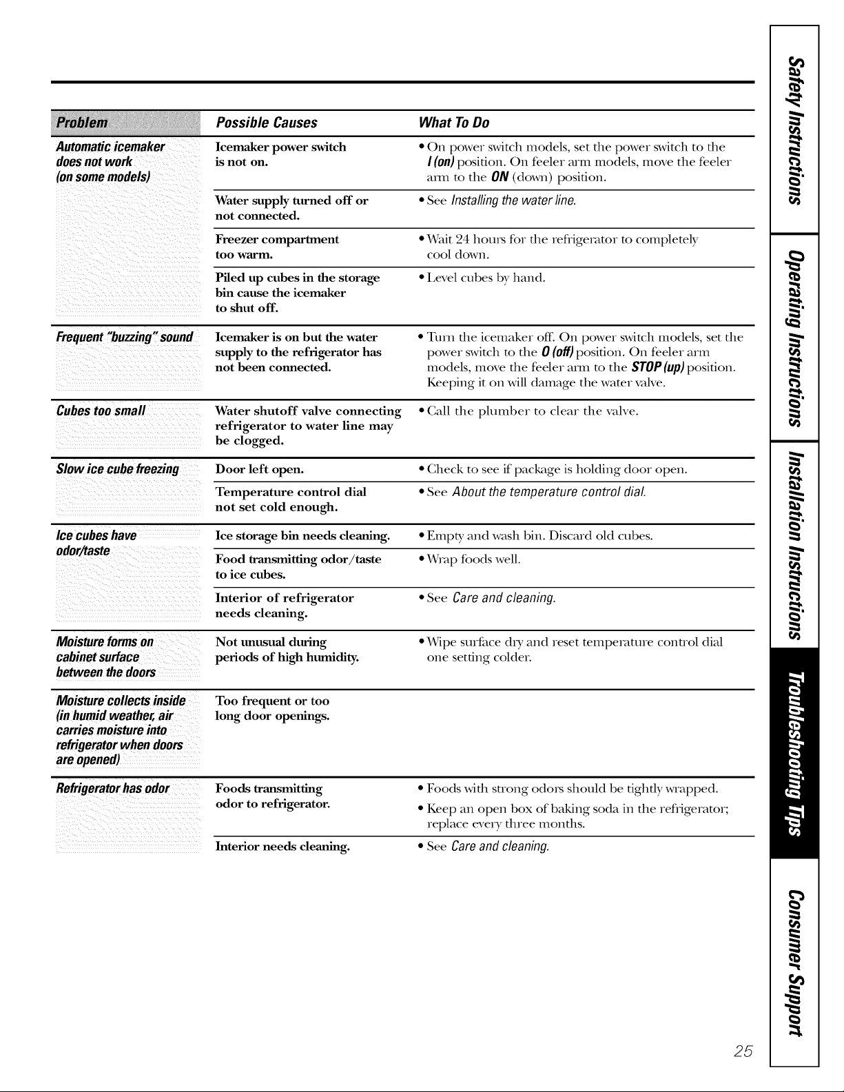
Possible Causes What ToDo
Automatic icemaker Icemaker power switch • 0)1 power switch models, set file power switch to file
does not work is not on. I(on) position. 011 feeler arm models, move the feeler
(onsome models) am1 to the ON (down) position.
Water supply turned off or • See Installing the water line.
not connected.
Freezer compartment e_Vait _4 hom_ for the refligemtor to completely
too warm. cool down.
Piled up cubes in the storage • 1,evel cubes by hand.
bin cause the icemaker
to shut off.
Frequent "buzzing" sound Icemaker is on but the water • Turn the iceinaker off. On power switch models, set the
supply to the refrigerator has power switch to the 0 (off) position. On feeler arm
not been connected, models, move the feeler am1 m the STOP(up)position.
Keeping it on will damage the water valve.
Cubestoo small Water shutoff valve connecting • (;all the plumber to clear the valve.
refrigerator to water line may
be clogged.
Slow ice cube freezing Door left open. • Check to see if package is hoMing door open.
Temperature control dial • See About the temperature control dial
not set cold enough.
Ice cubes have Ice storage bin needs cleaning. EInpt_ and wash bin. Discard old cubes.
odor/taste
Food transmitting odor/taste • Wrap foods well.
to ice cubes.
e
Interior of refrigerator • See Care and cleaning.
needs cleaning.
Moisture forms on Not unusual during • \Vipe surface (h T and reset temperature control dial
cabinet surface periods of high humidity, one setting coldeL
between thedoors
Moisturecollectsinside
(inhumidweather,air
Too frequent or too
long door openings.
carriesmoistureinto
refrigeratorwhendoors
areopened)
Refrigerator has odor Foods transmitting • Foods with strong o(lo15 should be tightly wrapped.
odor to refrigerator. • Keep an open box of baking soda in the refrigerator;
replace every three months.
Interior needs cleaning. • See Care and cleaning.
25
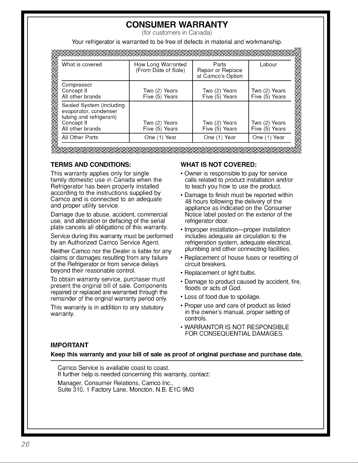
CONSUMER WARRANTY
(for customers in Canada)
Your refrigerator is warranted to be free of defects in material and workmanship.
What is covered How Long Warranted Parts Labour
Compressor
Concept II Two (2) Years Two (2) Years Two (2) Years
leb.31
All other brands Five (5) Years Five (5) Years Five (5) Years
1(__3/
Sealed System (including
id¢_l
evaporator, condenser
tubing and refrigerant)
Concept II
All other brands
All Other Parts One (1) Year One (1) Year One (1) Year
_eb.3_
I
TERMS AND CONDITIONS:
This warranty applies only for single
family domestic use in Canada when the
Refrigerator has been properly installed
according to the instructions supplied by
Camco and is connected to an adequate
and proper utility service.
Damage due to abuse, accident, commercial
use, and alteration or defacing of the serial
plate cancels all obligations of this warranty.
Service during this warranty must be performed
by an Authorized Camco Service Agent.
Neither Camco nor the Dealer is liable for any
claims or damages resulting from any failure
of the Refrigerator or from service delays
beyond their reasonable control.
To obtain warranty service, purchaser must
present the original bill of sale. Components
repaired or replaced are warranted through the
remainder of the original warranty period only.
This warranty is in addition to any statutory
warranty.
(From Date of Sale) Repair or Replace
at Camco's Option
Two (2) Years
Five (5) Years
Two (2) Years
Five (5) Years
WHAT IS NOT COVERED:
• Owner is responsible to pay for service
calls related to product installation and/or
to teach you how to use the product.
• Damage to finish must be reported within
48 hours following the delivery of the
appliance as indicated on the Consumer
Notice label posted on the exterior of the
refrigerator door.
• Improper installation--proper installation
includes adequate air circulation to the
refrigeration system, adequate electrical,
plumbing and other connecting facilities.
• Replacement of house fuses or resetting of
circuit breakers.
• Replacement of light bulbs.
• Damage to product caused by accident, fire,
floods or acts of God.
Loss of food due to spoilage.
Proper use and care of product as listed
in the owner's manual, proper setting of
controls.
Two (2) Years
Five (5) Years
• WARRANTOR IS NOT RESPONSIBLE
FOR CONSEQUENTIAL DAMAGES.
26
IMPORTANT
Keep this warranty and your bill of sale as proof of original purchase and purchase date.
Camco Service is available coast to coast.
If further help is needed concerning this warranty, contact:
Manager, Consumer Relations, Camco Inc.,
Suite 310, 1 Factory Lane, Moncton, N.B. ElC 9M3
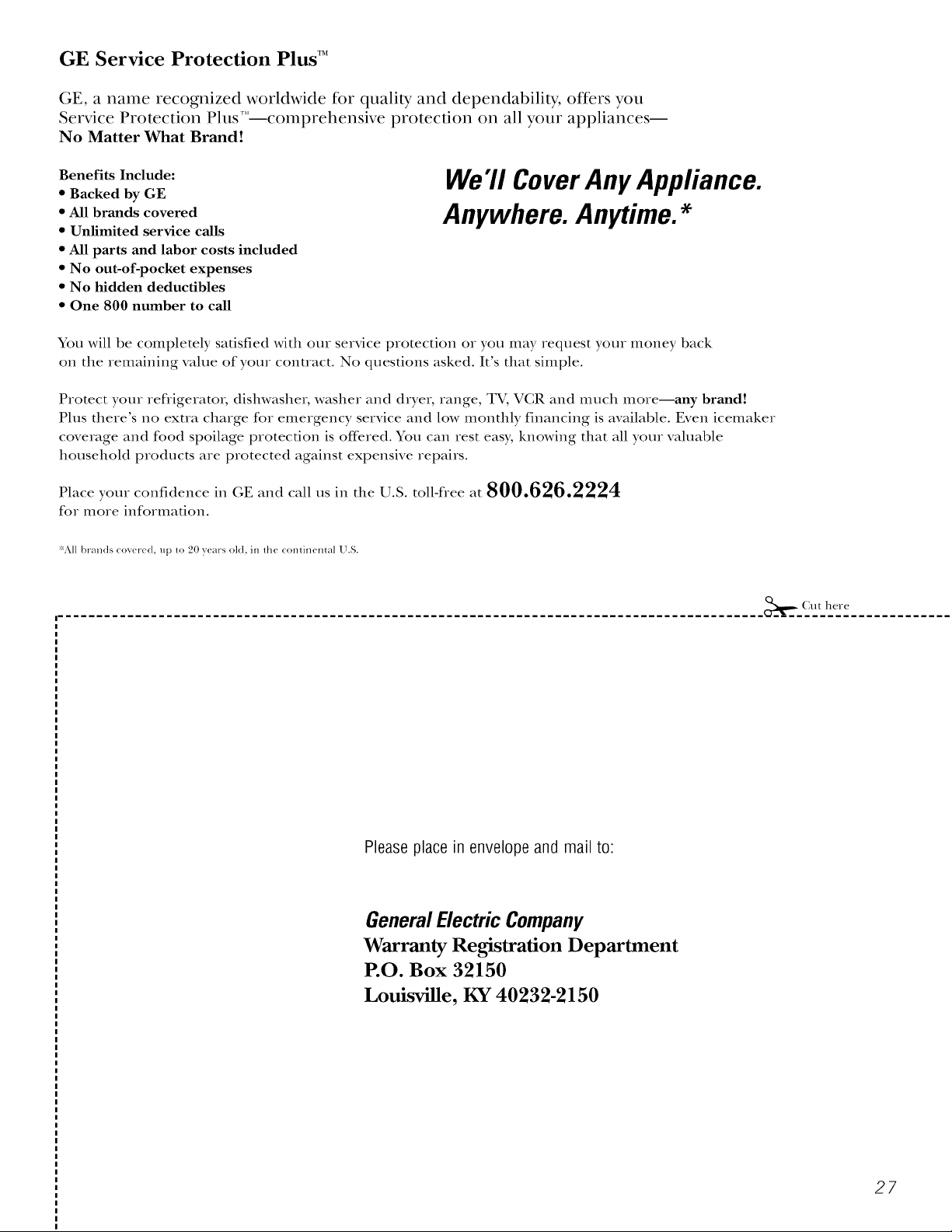
GE Service Protection Plus TM
GE, a name recognized worldwide R)r quality and dependability, offers you
Service Protection Plus'_'--comprehensive protection on all your appliances--
No Matter What Brand!
Benefits Include:
* Backed by GE
* All brands covered
* Unlimited service calls
* All parts and labor costs included
* No out-of-pocket expenses
* No hidden deductibles
* One 800 number to call
We71 CoverAnyAppliance.
Anywhere. Anytime.*
You will be completely satisfied with our service protection or you may request your money back
on the remaining value of your contract. No questions asked. It's that simple.
Protect your refligeratox; dishwasher, washer and dryer, range, TV, VCR and much more--any brand!
Plus there's no exua charge for emergency service and low monthly financing is available. Even icemaker
coverage and food spoilage protection is off>red. You can rest easy, knowing that all your valuable
household products are protected against expensive repairs.
Place your con_dence in GE and call us in the U.S. toll-free at 800.626.2224
for more information.
_%11brands cover_ d, up lo 20 years old, in lhe conlinenlal U.S.
.......................................... _z_.-_u t here
Please place in envelope and mail to:
General Electric Company
Warranty Registration Department
P.O. Box 32150
Louisville, KY 40232-2150
27
 Loading...