

Page 1
Installation Instructions
27" & 30" Electric Built-ln Wall Ovens
Questions? Call 1,800,GE,CARES (1,800,432,2737) or visit www,GEAppliances,com
In Canada, call 1,800,561,3344 or visit www,GEAppliances,ca
BEFORE YOU BEGIN
Read these instructions completely and
carefully.
" IMPORTANT -- Savetheseinstructions
for local inspector's use.
" IMPORTANT -- Observea, governing
codes and ordinances.
• Note to Installer - Be sure to leave these
instructions with Consumer.
ATTENTION INSTALLER: A, electric: wall ovens must be hard-wired (direct-wired)into an
approved junction box. A plug and receptacle is NOT permitted on these products.
FOR YOUR SAFETY:
^-.WARNING:Beforebeginningtheinstallation, switch power off at the service panel and
lock the service disconnecting means to prevent power from being switched on accidentally. When the
service disconnecting means cannot be locked, securely fasten a prominent warning device, such as a tag,
to the service panel.
Be sure the oven is securely irrstalled in a cabinet that is firmly attached to the house structure.
Weight on the oven door could cause the oven to tip arrd result in irrjury. Never allow anyorre to climb, sit,
stand or hang on the oven door.
Make sure the wall coverings, counters and cabinets around the oven can withstand the heat
(up to 200°F [93.3°C]) generated by the oven.
MATERIALS YOU MAY NEED
Junction Box
Wire Nuts
Strain Relief Clamp for 1/2" Corrduit
36" (91 ca) of String
REMOVE PACKAGING MATERIALS
Failure to remove packaging materials could result in damage to the appliance. Remove all packing
parts from oven, racks and heating elements. Remove protective film and labels on the outer door
and control panel. Also, remove plastic: on trims and panel, all tape around the oven and any shipping
screws securing the oven to the base pad. Open oven door and remove literature pack and oven
racks. Remove the bottom trim from the top of the oven. It will be installed at the end of the installation
process. The trim is wrapped separately and taped to the top of the unit. Remove pedestal rails from
seperate box and set aside (30" Double Wall Ovens Only).
• Note to Consumer - Keep these instructions
for future reference.
• Skill level- Installation of this appliance
requires a qualified installer or electrician.
• Proper installation is the responsibility
of the installer.
, Product failure due to improper installation
is not covered under Warranty.
, Product is for indoor use only.
TOOLS YOU MAY NEED
1/8" Drill Bit arrd Electric or Hand Drill
Phillips Screwdriver
Wire Strippers
7/18" Nut Driver
T20 Screwdriver (hinge bracket)
1/4" Nut Driver
DESIGN INFORMATION
SINGLE OVEN INSTALLATIONS
The single oven may be installed in a cabinet alone or above a warming drawer. The single oven may also
be irrstalled below a countertop or below specified cooktops. See the label on top of the oven for approved
models.
DOUBLE OVEN INSTALLATIONS
A double oven may be irrstalled in a cabinet alone or above a warming drawer. See the label on top of the
oven for approved models.
IMPORTANT: Always refer to irrdividual irrstallation irrstructions packed with each product for specific
requirements.
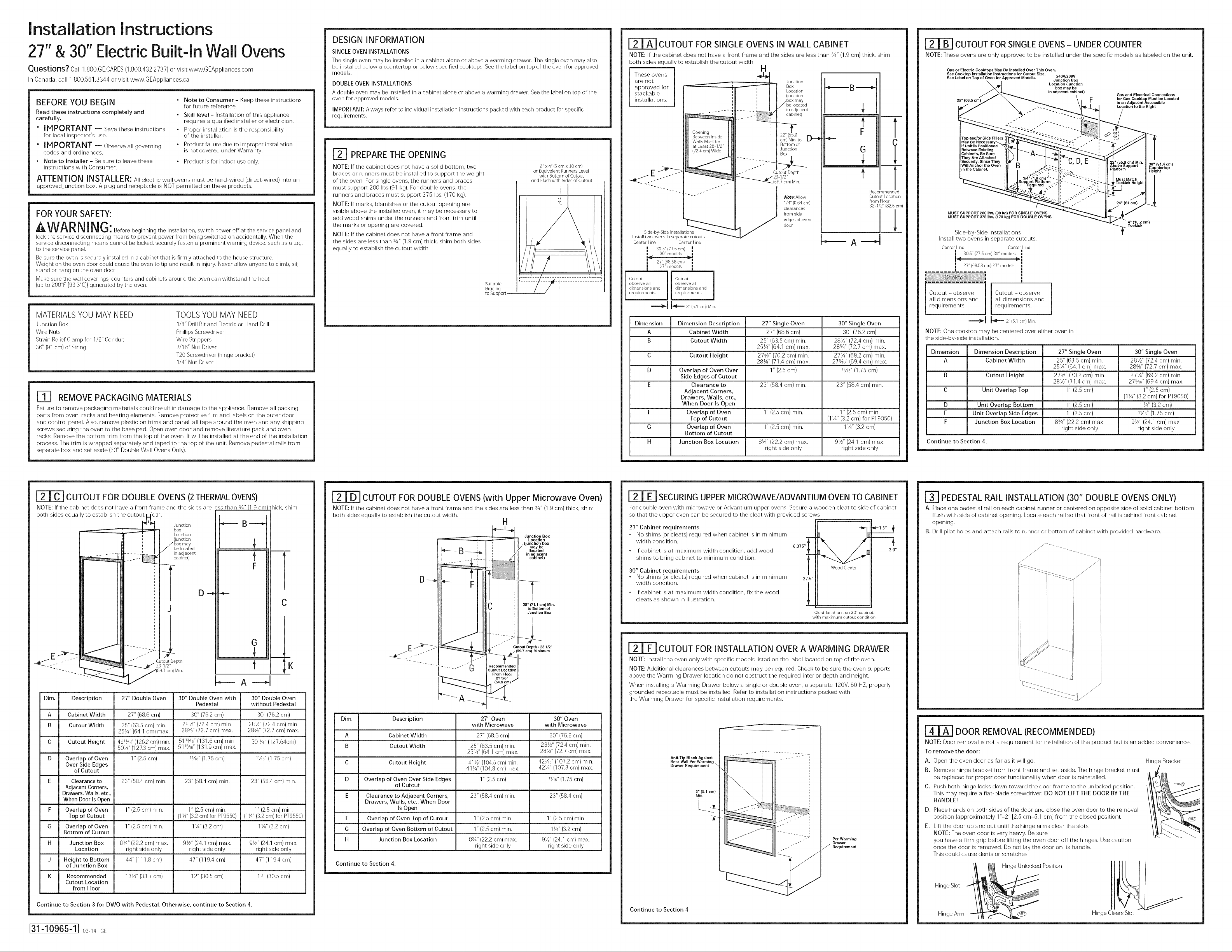
F2I PREPARE THE OPENING
NOTE: If the cabinet does not have a solid bottom, two
braces or runners must be installed to support the weight
of the oven. For single ovens, the runners and braces
must support 200 Ibs (91 kg). For double ovens, the
runners and braces must support 375 Ibs. (170 kg).
NOTE: If marks, blemishes or the cutout opening are
visible above the installed oven, it may be necessary to
add wood shims under the runners and front trim until
the marks or opening are covered.
NOTE: If the cabinet does not have a front frame and
the sides are less than 3/4" (1.9 cm) thick, shim both sides
equally to establish the cutout width.
Suitable
Bracing
to Support
2" x 4"(5 cm x 10 cm)
or Equivalent Runners Level
with Bottom of Cutout
and Flush with Bides of Cutout
CUTOUT FOR SINGLE OVENS IN WALL CABINET
NOTE: If the cabinet does not have a front frame and the sides are less than 3/4"(1.9 cm) thick, shim
both sides equally to establish the cutout width.
These ovens
are not
approved for "_='_ B
stackable
installations.
Opening
Between Inside
Walls Must he
at Least 28 1/2"
(72,4 ca) Wide
Sided)y Side Installations
Install two ovens in separate cutouts
Center Line Center Line
305" (77.5ca)
30" models u
!
y 2T' (68.5Bca)
_t 27"models
observe all I observe all
dimensions and dimensions and
Cutout Cutout i
req rements, requirements
Dimension Dimension Description 27" Single Oven 30" Single Oven
A Cabinet Width 27" (68.6 cm) 30" (76.2 cm)
B Cutout Width 25" (63.5 cm) min. 281//' (72.4 cm) min.
C Cutout Height 27%" (70.2 cm) min. 271/4" (69.2 cm) min.
D Overlap of Oven Over 1" (2.5 cm) 1Xd' (1.75 cm)
E Clearance to 23" (58.4 cm) min. 23" (58.4 cm) min.
F Overlap of Oven 1" (2.5 cm) min. 1" (2.5 cm) min.
G Overlap of Oven 1" (2.5 cm) min. 11/4"(3.2 cm)
H Junction Box Location 8_" (22.2 cm) max. 91//' (24.1 cm) max.
Side Edges of Cutout
Adjacent Corners,
Drawers, Walls, etc.,
When Door Is Open
Top of Cutout (11A"(3.2 cm) for PT9050)
Bottom of Cutout
H
Junction
Box
Location
(junction
in a d acent
cabinet)
22"(55.9
cm)Min to LJ='_
Bottomof
Junction
Box
Cutout Depth
(597ca) Min
Note: Allow
1/4" (064 ca)
clearances
from side
edges of oven
door
.................... ........
F
G
t
Recommended
Cutout Location
from Floor
32 1/2"(82,6ca)
b--
25X" (64.1 cm) max. 28%" (72.7 cm) max.
28W' (71.4 ca) max. 27_?' (69.4 ca) max.
right side only right side only
m
C
v
A
1
CUTOUT FOR SINGLE OVENS- UNDER COUNTER
NOTE: These ovens are only approved to be installed under the specific: models as labeled on the unit.
Gas or Electric Cooktops May Be Installed Over This Oven.
See Cooktop installation Instructioms for Cutout Size. 240W208V
See Label on Top of Oven for Approved Models• Junction Box
25" (63.5 ca)
Location (junction
box may be
in adjacent cabinet)
Gas and Electrical Connections
for Gas Cooktop Must be Located
in an Adjacent Accessible
Location to the Right
35" (91.4 cm)
Countertop
Height
_1
MUST SUPPORT 200 Ibs. (90 kg) FOR SINGLE OVENS
MUST SUPPORT 375 Ibs. (170 kg) FOR DOUBLE OVENS
Side-by-Side Installations
Install two ovens in separate cutouts.
Center Line Center Line
I 305" (77.5ca) 30" models
"(68.58cm) 27"models
!
Cutout - observe
all dimensions and
requirements.
_l _ 2 'r (51 crn)M_n
NOTE: One cooktop may be centered over either oven in
the side-by-side installation.
Dimension Dimension Description 27" Single Oven 30" Single Oven
A Cabinet Width 25" (63.5 cm) min. 281//' (72.4 cm) min.
B Cutout Height 27%" (70.2 cm) min. 271/4" (69.2 cm) min.
C Unit Overlap Top 1" (2.5 cm) 1" (2.5 cm)
D Unit Overlap Bottom 1" (2.5 cm) 11/4"(3.2 cm)
E Unit Overlap Side Edges 1" (2.5 cm) 1X6" (1.75 cm)
F Junction Box Location 8¾" (22.2 cm) max. 91/z'' (24.1 cm) max.
Continue to Section 4.
"!
I
I
Cutout - observe
all dimensions and
requirements.
25X" (64.1 cm) max. 28%" (72.7 cm) max.
28W' (71.4 ca) max. 27_6" (69.4 ca) max.
(I X" (3.2 cm) for PT9050)
right side only right side only
CUTOUT FOR DOUBLE OVENS (2 THERMAL OVENS)
NOTE: If the cabinet does not have a front flame and the sides are less than 3/4"l1.9 cm)
both sides equally to establish the cutout i_jdth.
_ i . Box
.......... L I in adjacent
_'I_ "1 Junction _ B
_ ', I Location
, J (junction
', ] /box may
! I /be located
_ - __ - cahinet)
hick, shim
t
F
D-_ _-
J
G
-"" _ Cutout Depth
_----_" 23 1/2"
(59,7 cm) Min,
Dim. Description 27" Double Oven 30" Double Oven with 30" Double Oven
A Cabinet Width 27" (68.6 ca) 30" (76.2 ca) 30" (76.2 ca)
B Cutout Width 25" (63.5 ca) rain. 28W' (72.4 ca) rain. 28Y/' (72.4 ca) rain.
C Cutout Height 491_t/' (126.2 cm) min. 51 _:_6"(131.6 ca) min. 50 W' (127.64cm)
D Overlap of Oven 1" (2.5 ca) 1Xd' (1.75 ca) 1Xd' (1.75 ca)
Over Side Edges
of Cutout
E Clearance to 23" (58.4 ca) rain. 23" (58.4 ca) rain. 23" (58.4 ca) rain.
Adjacent Corners,
Drawers, Walls, etc.,
When Door Is Open
F Overlap of Oven 1" (2.5 ca) rain. 1" (2.5 ca) rain. 1" (2.5 ca) rain.
Top of Cutout (1X" (3.2 cm) for P19550) (1X" (3.2 cm) for P19550)
G Overlap of Oven 1" (2.5 cm) rain. 1X" (3.2 cm) 1X" (3.2 cm)
Bottom of Cutout
H Junction Box 8¾" (22.2 cm) max. 9Y/' (24.1 cm) max. 9Y/' (24.1 cm) max.
J Height to Bottom 44" (111.8 ca) 47" (119.4 ca) 47" (119.4 ca)
K Recommended 13X" (33.7 ca) 12" (30.5 ca) 12" (30.5 ca)
Location right side only right side only right side only
of Junction Box
Cutout Location
from Floor
25X" (64.1 ca) max. 28%" (72.7 ca) max. 28%" (72.7 ca) max.
50W' (127.3 ca) max. 511_6" (131.9 ca) max.
Pedestal without Pedestal
t
CUTOUT FOR DOUBLE OVENS (with Upper Microwave Oven)
NOTE: If the cabinet does not have a front frame and the sides are less than 3/4"(1.9 cm) thick, shim
both sides equally to establish the cutout width.
H
Junction Box
Location
(junction box
/ may be
located
in adjacent
cabinet)
28" (71.1 ca) Min,
• (59.7 ca) Minimum
A
Dim. Description 27" Oven 30" Oven
A Cabinet Width 27" (68.6 ca) 30" (76.2 ca)
B Cutout Width 25" (63.5 cm) rain. 28Y/' (72.4 cm) rain.
C Cutout Height 41W' (104.5 crn) rain. 42_d' (107.2 cm) min.
D Overlap of Oven Over Side Edges 1" (2.5 cm) 11A6"(1.75 cm)
E Clearance to Adjacent Corners, 23" (58.4 cm) rain. 23" (58.4 cm)
Drawers, Walls, etc., When Door
F Overlap of Oven Top of Cutout 1" (2.5 ca) min. 1" (2.5 ca) rain.
G Overlap of Oven Bottom of Cutout 1" (2.5 ca) rain. 11A" (3.2 ca)
H Junction Box Location 8¾" (22.2 cm) max. 91½"(24.1 cm) max.
Continue to Section 4.
of Cutout
Is Open
with Microwave with Microwave
25X" (64.1 cm) max. 28%" (72.7 cm) max.
41X" (104.8 cm) max. 42X" (107.3 cm) max.
right side only right side only
SECURING UPPER MICROWAVE/ADVANTIUM OVEN TO CABINET
For double oven with microwave or Advantium upper ovens. Secure a wooden cleat to side of cabinet
so that the upper oven can be secured to the cleat with provided screws
27" Cabinet requirements
• No shims (or cleats) required when cabinet is in minimum
width condition.
• If cabinet is at maximum width condition, add wood
shims to bring cabinet to minimum condition.
30" Cabinet requirements
* No shims (or cleats) required when cabinet is in minimum
width condition.
• If cabinet is at maximum width condition, fix the wood
cleats as shown in illustration.
m
6.375"_
t
27.5"
Cleat locations on 30" cabinet
with maximum cutout condition
Wood Cleats
•1=1.6" _,
CUTOUT FOR INSTALLATION OVER A WARMING DRAWER
NOTE: Install the oven only with specific: models listed on the label located on top of the oven.
NOTE: Additional clearances between cutouts may be required. Check to be sure the oven supports
above the Warming Drawer location do not obstruct the required interior depth and height.
When installing a Warming Drawer below a single or double oven, a separate 120V, 60 HZ, properly
grounded receptacle must be installed. Refer to installation instructions packed with
the Warming Drawer for specific: installation requirements.
1
Anti-Tip Block Against
Rear Wall Per Warming
Drawer Requirement
2" (5.1 cm)
Min.
Per Warming
Drawer
Requirement
3.0"
l_] PEDESTAL RAIL INSTALLATION (30" DOUBLE OVENS ONLY)
A. Place one pedestal rail on each cabinet runner or centered on opposite side of solid cabinet bottom
flush with side of cabinet opening. Locate each rail so that front of rail is behind front cabinet
opening.
B. Drill pilot holes and attach rails to runner or bottom of cabinet with provided hardware.
.......-_-_----____ //
...........111- _///
DOOR REMOVAL (RECOMMENDED)
NOTE: Door removal is not a requirement for installation of the product but is an added convenience.
To remove the door:
A. Open the oven door as far as it will go.
B. Remove hinge bracket from front frame and set aside. The hinge bracket must
be replaced for proper door functionality when door is reinstalled.
C. Push both hinge locks down toward the door frame to the unlocked position.
This may require a flat-blade screwdriver. DO NOT LIFT THE DOOR BY THE
HANDLE!
D. Place hands on both sides of the door and (:lose the oven door to the removal
position (approximately 1"-2" [2.5 cm-5.1 cm] from the closed position).
E. Lift the door up and out until the hinge arms (:lear the slots.
NOTE: The oven door is very heavy. Be sure
you have a firm grip before lifting the oven door offthe hinges. Use caution
once the door is removed. Do not lay the door on its handle.
This could cause dents or scratches.
/_ I!_ Hinge Unlocked
Position
Hinge Bracket
Continue to Section 3 for DWO with Pedestal. Otherwise, continue to Section 4.
J31-10965-1J 0s-14GE
Continue to Section 4
Hinge Arm _!l=(_
Hinge Clears Slot
Page 2
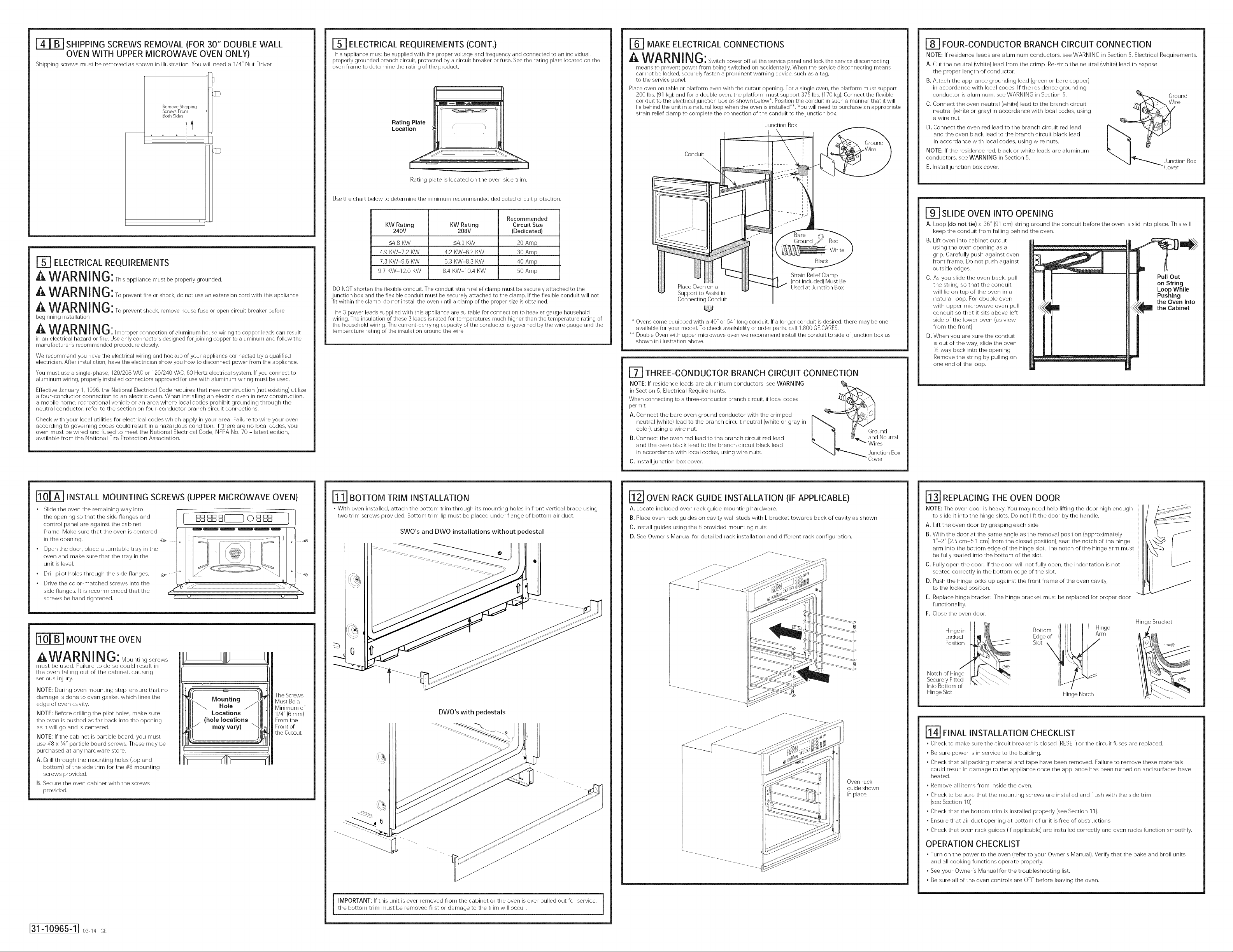
SHIPPING SCREWS REMOVAL (FOR 30" DOUBLE WALL
OVEN WITH UPPER MICROWAVE OVEN ONLY)
Shipping screws must be removed as shown in illustration. You will need a 1/4" Nut [)river.
RemoveShipping
ScrewsFrom
BothSides
i
[_ ELECTRICAL REQUIREMENTS (CONT.)
This appliance must be supplied with the proper voltage and frequency and connected to an irrdividual,
properly grounded branch circuit, protected by a circuit breaker or fuse. See the rating plate located on the
oven frame to determine the rating of the product.
Rating P|ate
Location- ;
[
Rating plate is located on the oven side trim.
Use the chart below to determine the minimum recommended dedicated circuit protection:
r_ MAKE ELECTRICAL CONNECTIONS
a, WARNING: Switch power off at the service panel and Iockthe service disconnecting
means to prevent power From being switched on accidentally. When the service disconnecting means
cannot be locked, securely fasten a prominent warning device, such as a tag,
to the service panel.
Place oven on table or platform even with the cutout opening. For a single oven, the platform must support
200 Ibs. (91 kg)i and for a double oven, the platform must support 375 Ibs. (170 kg). Connect the flexible
corrduit to the electrical junction box as shown below _. Position the corrduit in such a manner that it will
lie behind the unit in a natural loop when the oven is installed <*. You will need to purchase an appropriate
strain relief clamp to complete the connection of the conduit to thejunction box.
,Junction Box
Conduit
[=8-7FOUR-CONDUCTOR BRANCH CIRCUIT CONNECTION
NOTE: If residence leads are aluminum conductors, see WARNING in Section 5, Electrical Requirements.
A. Cut the neutral (white) lead from the crimp. Re-strip the neutral (white) lead to expose
the proper length of conductor.
B. Attach the appliance grounding lead (green or bare copper)
in accordance with local (:()des. If the residence grounding
conductor is aluminum, see WARNING in Section 5.
C. Connect the oven neutral (white) lead to the branch circuit
neutral (white or gray) in accordance with local (:()des, using
a wire nut.
D. Connect the oven red lead to the branch circuit red lead
and the oven black lead to the branch circuit black lead
in accordance with local (:()des, using wire nuts.
NOTE: If the residence red, black or white leads are aluminum
conductors, see WARNING in Section 5.
E. Install junction box cover.
""4 "_ ,Junction Box
Gro;nd
Cover
J_ ELECTRICAL REQUIREMENTS
WARNING:Thisapp,iancere.stbeproper,ygrounded
a,WARNING:To prevent fire or shock, do not use an extension cord with this appliance.
A WARNING: To prevent shock, remove house fuse or open circuit breaker before
beginning irrstallation.
WARNING:Improper connection of alurninum house wiring to copper leads can result
in an electrical hazard or fire. Use only corrnectors designed for joining copper to aluminum arrd follow the
manufacturer's recommended procedure closely.
We recommend you have the electrical wiring arrd hookup of your appliance corrnected by a qualified
electrician. After irrstallation, have the electrician show you how to disconnect power from the appliance.
You must use a single-phase, 120/208 VAC or 120/240 VAC,60 Hertz electrical system. If you corrnect to
aluminum wiring, properly installed corrnectors approved for use with aluminum wiring must be used.
Effective ,January 1, 1996, the National Electrical Code requires that new construction (not existing) utilize
a four-conductor connection to an electric oven. When installing an electric oven in new construction,
a mobile home, recreational vehicle or an area where local codes prohibit grounding through the
neutral conductor, refer to the section on four-conductor branch circuit connections.
Check with your local utilities for electrical (:()des which apply in your area. Failure to wire your oven
according to governing codes could result in a hazardous condition. If there are no local (:()des, your
oven must be wired and fused to meet the National Electrical Code, NFPA No. 70 - latest edition,
available from the National Fire Protection Association.
KW Rating KW Rating Circuit Size
Recommended
240V 208V (Dedicated)
<4.8 KW <4.t KW 20 Amp
4.9 KW-7.2 KW 4.2 KW-6.2 KW 30 Amp
7.3 KW-9.6 KW 6.3 KW-8.3 KW 40 Amp
9.7 KW-12.0 KW 8.4 KW-IO.4 KW 50 Amp
DO NOT shorten the flexible corrduit. The conduit strain relief clamp must be securely attached to the
junction box and the flexible corrduit must be securely attached to the clamp. If the flexible corrduit will not
fit within the clamp, do not irrstall the oven until a clamp of the proper size is obtained.
The 3 power leads supplied with this appliance are suitable for connection to heavier gauge household
wiring. The irrsulation of these 3 leads is rated for temperatures much higher than the temperature rating of
the household wiring. The current-carrying capacity of the conductor is governed by the wire gauge arrd the
temperature rating of the irrsulation around the wire.
Strain Relief Clamp
Place Oven on a
Support to Assist in
Connecting Conduit
< Ovens come equipped with a 40" or 54" long conduit. If a longer corrduit is desired, there may be one
available for your model. To check availability or order parts, call 1.800.GE.CARES.
*< Double Oven with upper microwave oven we recommend install the corrduit to side ofjunction box as
shown in illustration above.
(not included) Must Be
Used at ,Junction Box
[_ THREE-CONDUCTOR BRANCH CIRCUIT CONNECTION
NOTE: If residence leads are aluminum conductors, see WARNING
in Section 5, Electrical Requirements.
When corrnecting to a three-conductor branch circuit, if local codes
permit:
A. Connect the bare oven ground conductor with the crimped
neutral (white) lead to the branch circuit neutral (white or gray in
color), using a wire nut.
B. Connect the oven red lead to the branch circuit red lead
and the oven black lead to the branch circuit black lead
in accordance with local (:()des, using wire nuts.
C. Install junction box cover.
[_ __ound
I _ and Neutral
L 'Wires
"",,J "_ ,Junction Box
Cover
|SLIDE OVEN INTO OPENING
A. Loop (do not tie)a 36" (91cm) stringaround the conduit before the oven isslidintoplace.Thiswill
keep the conduit from fallingbehind the oven.
B. Liftoven intocabinet cutout
using the oven opening as a
grip.Carefullypush against oven
front frame. Do not push against
outside edges.
C. As you slide the oven back, pull
the string so that the conduit
will lie on top of the oven in a
natural loop. For double oven
with upper microwave oven pull
conduit so that it sits above left
side of the lower oven (as view
from the front).
D. When you are sure the conduit
is out of the way, slide the oven
s/4way back into the opening.
Remove the string by pulling on
one end of the loop.
Pull Out
on String
Loop While
Pushing
the Oven Into
the Cabinet
INSTALL MOUNTING SCREWS (UPPER MICROWAVE OVEN)
• Slide the oven the remaining way into
the opening so that the side flanges and
control panel are against the cabinet
frame. Make sure that the oven is (:entered
in the opening.
• Open the door, place a turntable tray in the
oven and make sure that the tray in the
unit is level.
• Drill pilot holes through the side flanges.
• Drive the color-matched screws into the
side flanges. It is recommended that the
screws be hand tightened.
MOUNT THE OVEN
AWARN I N G: Mountings( rews
must be use(]. Failure to do so could result in
the oven falling out of the cabinet, causing
serious injury.
NOTE: During oven mounting step, ensure that no
damage is done to oven gasket which lines the
edge of oven cavity.
NOTE: Before drilling the pilot holes, make sure
the oven is pushed as far back into the opening
as it will go and is centered.
NOTE: If the cabinet is particle board, you must
use #8 x s/4" particle board screws. These may be
purchased at any hardware store.
A. Drill through the mounting holes (top and
bottom) of the side trim for the #8 mounting
screws provided.
B. Secure the oven cabinet with the screws
provided.
Mounting
Hole
Locations
(hole locations
may vary)
The Screws
Must Be a
Minimum of
1/4" (6 ram)
From the
Front of
the Cutout.
BOTTOM TRIM INSTALLATION
• With oven installed, attach the bottom trim through its mounting holes in front vertical brace using
two trim screws provided. Bottom trim lip must be placed under flange of bottom air duct.
SWO's and DWO installations without pedestal
0
DWO's with pedesta Is
OVEN RACK GUIDE INSTALLATION (IF APPLICABLE)
A. Locate included oven rack guide mounting hardware.
B. Place oven rack guides on cavity wall studs with L bracket towards back of cavity as shown.
C. Install guides using the 8 provided mounting nuts.
D. See Owner's Manual for detailed rack installation and different rack configuration.
Oven rack
guide shown
in place.
! REPLACING THE OVEN DOOR
NOTE: The oven door isheavy. You may need help liftingthe door high enough
to slideitintothe hinge slots.Do not liftthe door by the handle.
A.
Lift the oven door by grasping each side.
B.
With the door at the same angle as the removal position (approximately
1"-2" [2.5 cm-5.1 cm] from the closed position), seat the notch of the hinge
arm into the bottom edge of the hinge slot. The notch of the hinge arm must
be fully seated into the bottom of the slot.
C,
Fully open the door. If the door will not fully open, the indentation is not
seated correctly in the bottom edge of the slot.
D.
Push the hinge locks up against the front frame of the oven cavity,
to the locked position.
E.
Replace hinge bracket. The hinge bracket must be replaced for proper door
functionality.
F.
Close the oven door.
Hinge Bracket
Hingein I _
LockedI1 I/'
Bottom [ Hinge
Edge of I II l i
s,ot\/tl I>/
Position_
Securely Fitted ik_\_.'"-. \
Into Bottom of ....
Hinge Slot
._ I[1_ \. \\ "-.
FINAL INSTALLATION CHECKLIST
* Check to make sure the circuit breaker is closed (RESET) or the circuit fuses are replaced.
* Be sure power is in service to the building.
, Check that all packing material and tape have been removed. Failure to remove these materials
could result in damage to the appliance once the appliance has been turned on and surfaces have
heated.
, Remove all items from inside the oven.
, Check to be sure that the mounting screws are installed and flush with the side trim
(see Section 10).
, Check that the bottom trim is installed properly (see Section 11).
, Ensure that air duct opening at bottom of unit is free of obstructions.
, Check that oven rack guides (if applicable) are installed correctly and oven racks function smoothly.
OPERATION CHECKLIST
* Turn on the power to the oven (refer to your Owner's Manual). Verify that the bake and broil units
and all cooking functions operate properly.
* See your Owner's Manual for the troubleshooting list.
* Be sure all of the oven controls are OFF before leaving the oven.
i'N i
Hinge Notch
J31-10965-1J 0s-140E
i MPORTANT: If this unit is ever removed from the cabinet or the oven is ever pulled out for service,the bottom trim must be removed first or damage to the trim will occur.
Page 3

Instrucciones de instalacion
Hornosdeparedelectricosempotradosde27"y30"
LPreguntas? Llame al 1,8OO,GE,CARES (1,800,432,2737) o visite GEAppliances,com
En Canada, Ilame al 1,8OO,561,3344 o visite www,GEAppliances,ca,
ANTES DE COMENZAR
Lea estas instrucciones per complete y con
detenimiento.
" IMPORTANTE - Guardee<asinstrucciones
para el use de inspectores locales.
" IMPORTANT - Cumplacon_odosloscodigosy
ordenanzas vigentes.
• Nota al instalador- Asegurese de dejar estas
instrucciones con el Consumidor.
ATENCIONINSTALADOR:Todosloshornosdeparedebctricos@bencontarconcabbadodeconexi0npermanente
(cabbad0direct0)dentr0deunacajadec0nexi0nesapr0bada,Enestospr0ductosNOsepermiteh c0nexi0ndeltip0"enchufeyreceptacud',
PARA SU SEGURIDAD:
A ADVE RTE NC ]A: Ant÷sd÷comenzar,ainsta,aciOn,desconect÷,aene,g,a
del panel de servicio y bloquee los medics de desconexion para evitar el accionamiento de la energia de manera
accidental. Cuando los medics de desconexion de servicio no pueden bloquearse, coloque sobre
el panel de servicio un dispositivo de advertencia bien visible, come una etiqueta.
El homo debe instalarse bien en un gabinete que se encuentre firmemente sujeto a la estructura de la casa. Si se
coloca peso sobre la puerta del homo, este puede volcarse y provocar lesiones. Nunca permita que nadie se suba,
siente, pare o cuelgue de la puerta del homo.
Verifique que el revestimiento de las paredes, mostradores y gabinetes ubicados alrededor del homo puedan
soportar el calor (hasta 200°F [93,3°C]) generado per el horno.
MATERIALES QUE PUEDE NECESITAR
Caja de conexiones
Tapones de alambre
Abrazadera de alivio de tension para conduct() de 1/2"
36" (91 cm) de cuerda
QUITE LOS MATERIALES DE EMPAQUE
No quitar los materiales de empaque puede provocar danes al electrodomestico. Quite todas las partes de
empaque del homo, bandejas y elementos de calentamiento. Quite la pelicula protectora y las etiquetas de
la puerta exterior y panel de control. Tambien, quite los elementos plasticos de los rebordes y panel, toda la
cinta que cubre el homo y los tornillos de envio que fian el homo a la almohadilla base. Abra la puerta del
homo y quite el material informative y las bandejas del borne. Quite el reborde inferior de la parte superior del
borne. Se colocara al final del proceso de instalacion. El reborde se encuentra envuelto en forma separada y
adherido en la parte superior de la unidad. Retire los rieles del pedestal de la caja que esta aparte y dejelos a
un costado (Hornos con Pared Doble de 30 _'Unicamente).
• Nota al consumidor - Conserve estas
instrucciones para referencia futura.
• Nivel de destreza - La instalacion de este
aparato requiere un instalador o electricista
calificados.
• El instalador tiene la responsabilidad de
efectuar una instalacion adecuada.
. La garantia no cubre las fallas del producto
provocadas per una instalacion incorrecta.
. Este producto solo se debe usar en areas
interiores.
HERRAMIENTAS NECESARIAS
Broca de perforadora de 1/8" y perforadora
electrica o de mane
Destornillador de estrella
Alicates pelacables
Dave de tuercas de 7/16"
Destornillador T20 (soporte de bisagra)
Dave de tuercas de 1/4"
INFORMACION DE DISE--O
INSTALACIONES DE HORNO 0NICe
El horno _]nico puede instalarse solo en un gabinete o sobre un cajon calentador. El horno _]nico tambien
puede instalarse debajo de un mostrador de encimera o debajo de las estufas especificadas. Vea la
etiqueta de la parte superior del homo para consul(at los modelos aprobados.
INSTALACIONES DE HORNO DOBLE
Puede instalarse un homo doble solo en un gabinete o sobre un cajon calentador. Yea la etiqueta de la
parte superior del horno para consul(at los modelos aprobados.
IMPORTANTE: Siempre consulte las instrucciones de instalaciones individuales enviadas con cada producto
para requerimientos especificos.
ILl PREPARE LAABERTURA
NOTA: Si el gabinete no cuenta con un rondo solido,
deben instalarse dos abrazaderas o guias para
soportar el peso del homo, Para hornos unicos, las
guias o abrazaderas deben soportar 200 Ibs (91 kgs).
Para hornos dobbs, las guias o abrazaderas deben
soportar 375 Ibs (170 kgs).
NOTA: Si marcas, imperfecciones o la abertura
resultaran visibles sobre el homo instalado, puede
ser necesario agregar cunas de madera bajo las
guias y el reborde frontal hasta cubrir las marcas
o la abertura,
NOTA: Si el gabinete no cuenta con un armazon
frontal y los lades son menores a un grosor de 3/4"
(1,9 cm), coloque cunas uniformemente sobre ambos
lades para establecer al ancho de la abertura.
Abrazadetas
adeeuadas --
para sostener
las gu_s
Guias de 2"x 4" (5 cm x 10 cm)
o equivalentes a nive| con
el fondo del recorte
y niveladas
costados de I_Labertura
ABERTURAPARA HORNOS UNICOS EN UN GABIENTE DEPARED
NOTA: Si el gabinete no cuenta con un armazon frontal y los lades son menores a un grosor de 3/4" (1,9 cm),
coloque cunas uniformemente sobre ambos lades para establecer al ancho de la abertura.
Estos homes
no estan
aprobados
para
instalaciones
apilables.
E _--}-_-
Instalacionesladeala
Instab dos homes en aberturas sep_t_a'_ _ lateralesde
Li......... tra, Li......... tra, -- --
b 30,5"(77,5cm) ! horno A
i 27'r (68'58 cm) fi
Abeltura cumpla Abertura cumpla
con todas las con todas las
dimensiones y dimensiones y
requerimientos, requerimientos,
DimensiOn Descripcion de la dimension Horno unico de 27" Homo unico de 30"
A Ancho del gabinete 27" (68,6 cm) 30" (762 cm)
B Ancho de la abertura 25" (63,5 cm) min. 281//` (72,4 cm) min.
C Altura de la abertura 27%" (70,2 cm) min. 271/4'' (69,2 cm) min.
D Superposicion del horno 1" (2,5 cm) 11A6"(1,75 cm)
E Espacio respecto 23" (58,4 cm) rain. 23" (58,4 cm) rain.
F Superposicion de la 1" (2,5 cm) min. 1" (2,5 cm) min.
G Superposicion de la 1" (2,5 cm) min. 11/4" (3,2 cm)
H Ubicacion de la caja 8¾" (22,2 cm) max. 91//' (24,1 cm) max.
db'____ _,_ desdelos
modelo 30" I
modelo 2711 l
_,_l,_ 2" (5rl crn) mln
sobre los costados
laterales de la abertura
de esquinas adyacentes,
cajones, paredes, etc.,
cuando la puerta
parte superior del homo (1X" (3.2 cm) para PT9050)
_arte inferior del homo
I
4
La abertura
entre ]as paredes
nternas debe ser
esta abierta
de la abertura
de la abertura
de conexiones solo lade derecho solo lade derecho
i
i
i
i
u
u
u
25X" (64,1 cm) max. 28%" (72,7 cm) max.
28W' (71,4 cm) max. 27_6" (69,4 cm) max.
Ubicancion
de la caja de
conexiones
(la caja de
conexiones
puede hallarse
en un gabinete
adyancente)
', 22"(55,9cm) Ur_==_
rain,hasta la
parte inferior
', de lacaja de
f
conexiones
Nota: Deje
1/4"(0,64cm)
de espacio
extremes
la puerta del
i' ._------B-===_
i
i
i
b----
t
F
G
t
Ubicancion
recomendada
de la abertura
desde el piso
32 1/2" (826 cm)
C
f
!
| ABERTURAPARAHORNOSUNICOS- BAJO ELMOSTRADORDEENCIMERA
NOTA: Estos hornos solo pueden instalarse b_jo los modelos especificos come se indica en la etiqueta
de la unidad.
Ins(ale dos homes en aberturas separadas.
Pueden instalarse estufas a gas o el_ctricas sobre este homo.
Vet las instrucciones de instalacibn de la estufa para el
tama5o de la abertura.
Ver la etiqueta de la parte superior del homo para UbicaciOn de la caja
modelos aprobados, de conexiones de
25" (53,5 cm) F
DEBE PODER SOSTENER 200 LBS. (90 kg) PARA HORNOS UNICOS
DEBE PODER SOSTENER 375 LBS. (170 kg) PARA HORNOS DOBLES
Instalaciones lade a lade
Linea central Linea central
!
1_30,5" (77,5cm) modelo30" }_'i
27"(6858 cm) modelo27" I
240V/208V
(la caja de conexiones
puede haHarse en un
gabinete adyacente)
Las conexiones de gas
y el_ctricas para estufas
a gas deben ubicarse en
una ubicacion adyacente
accesible sobre la derecha.
22" (55,9 cm) rain. 36" (91,4 cm)
sobre la plataforma Altura del mostrador
% Placa de protecciOn
de encimera
4" (10,2 cm)
I
Abertura - cumpla Abertura - cumpla
con todas las con todas las
dimensiones y dimensiones y
requerimientos, requerimientos.
_l _ 2 'r (5rl c_r,)MiD,
NOTA: Una estufa puede centrarse sobre cualquier
homo en la instalacion de lade a lade.
Dimension Descripcion de la dimension Horno unico de 27" Horno unico de 30"
A Ancho del gabinete 25" (63,5 cm) min. 28Y/' (72,4 cm) min.
B Altura de la abertura 27%" (70,2 cm) min. 271/4" (69,2 cm) min.
C Superposicion de la 1" (2,5 cm) 1" (2,5 cm)
D Superposicion de la 1" (2,5 cm) 11/4" (3,2 cm)
E Superposicion de la 1" (2,5 cm) 1_A6"(1#5 cm)
F Ubicacion de la caja 8¾" (22,2 cm) max. 91/z'' (24,1 cm) max.
Continue en la seccion 4.
unidad en parte superior (lY4" (3.2 cm) para PT9050)
unidad en parte inferior
unidad en costados laterales
de conexiones solo lade derecho solo lade derecho
25X" (64,1 cm) max. 28%" (72,7 cm) max.
28W' (71,4 cm) max, 27%6" (69,4 cm) max,
ABERTURA PARA HORNOS DOBLES (2 HORNOS TleRMICOS)
NOTA: Si el gabinete no cuenta con un armazon frontal y los lados son menores a un grosor de 3/4" (1,9 cm),
coloque cunas uniformemente sobre ambos lados para establecer al ancho de la abertura.
de la caja de
conexiones(la caja
de conexiones
puede ha]larse
Ubicadon
en un gabinete
/adyacente
t
F
J
G
-"" Profundidadde la
_-_-_/" abertura 23-!/2"
,_ (59 7 cm) mlnlmo
Dim. Descripcion Homo doble de 27" Homo doble de 30" Homo doble de 30"
A Ancho del gabinete 27" (68,6 cm) 30" (76,2 cm) 30" (76,2 cm)
B Ancho de la abertura 25" (63,5 cm) min. 28Y/' (72,4 cm) min. 28_½'' (72,4 cm) min.
C Altura de la abertura 491_A6'' (126,2 cm) min. 5113_6" (131,6 cm) min. 50 Y_" (127,64cm)
D Superposicion del 1" (2,5 cm) 1X6" (1,75 cm) 1X6" (1,75 cm)
homo sobre los
costados laterales de
la abertura
E Espacio respecto de 23" (58,4 cm) rain. 23" (58,4 cm) rain. 23" (58,4 cm) rain.
esquinas adyacentes,
cajones paredes, etc.,
cuando la puerta esta
abierta
F Superposicion de la 1" (2,5 cm) rain. 1" (2,5 cm) rain. 1" (2,5 cm) rain.
parte superior del (1X" (3.2 cm) para (1X" (3.2 cm) para
homo de la abertura PT9550) PT9550)
G Superposicion de 1" (2,5 cm) rain. 1X" (3,2 cm) 1X" (3,2 cm)
la parte inferior del
homo de la abertura
H Ubicacion de la caja 8¾" (22,2 cm) max. %½" (24,1 cm) max. %½" (24,1 cm) max.
J Altura hasta la parte 44" (111,8 cm) 47" (119,4 cm) 47" (119,4 cm)
K Ubicacion 13_A'' (33,7 cm) 12" (30,5 cm) 12" (30,5 cm)
Continue a la Seccion 3 para conocer detalles del DWO con Pedestal. De otra forma, continue a la Seccion 4.
de conexiones solo lado derecho solo lado derecho solo lado derecho
inferior de la caja de
conexiones
recomendada de la
abertura desde el piso
25X" (64,1 cm) max. 28%" (72,7 cm) max. 28%" (72.7 cm) max.
501/?' (127,3 cm) max. 511%6" (131,9 cm) max.
con pedestal sin pedestal
31-10965-1] os-_4_E
?
ABERTURAPARAHORNOS DOBLES(con homo de microondas superior)
NOTA: Si el gabinete no cuenta con un armazon frontal y los lados son menores a un grosor de 3/4"
(1,9 cm), coloque cunas uniformemente sobre ambos lados para establecer al ancho de la abertura.
H
UbicaciOn de la caja
28" (71,1 cm) m_n.
hasta la parte inferior
de la caja de conextones
~
UbicaciOn
desde el piso
A
Dim. Descripci0n Homo de 27" Homo de 30"
A Ancho del gabinete 27" (68.6 cm) 3(Y (76.2 cm)
B Ancho de la abertura 25" (63,5 cm) m(n. 28V/' (72,4 cm) m(n.
C Altura de la abertura 411_''(104,5 cm) min, 42_6" (107,2 cm) m(n.
D Superposicion del homo sobre los 1" (2,5 cm) _Ao" (1,75 cm)
costados laterales de la abertura
E Espacio respecto de esquinas 23" (58,4 cm) m(r_. 23" (58,4 cm)
adyacentes, cajones paredes, etc.,
cuando la puerta esta abierta
F Superposicion de la parte superior 1" (2,5 cm) m(r_. 1" (2,5 cm) m(r_.
G Superposicion de la parte inferior 1" (2,5 cm) m(r_. 1_A"(3,2 cm)
H Ubicacion de la caja de 8¾" (22,2 cm) max. 91½"(24,1 cm) max.
Continue en la seccion 4.
del homo de la abertura
del homo de la abertura
conexiones solo lade derecho solo lade derecho
con microondas con microondas
25X" (64,1 cm) max. 28%" (72,7 cm) max.
41X" (104,8 cm) max. 421A '' (107,3 cm) max.
COMO ASEGURAREL HORNO MICROONDAS/ADVANTIUM
SUPERIORAL GABINETE
Para homes dobbs come homes superiores (:on microondas o Advantium. Asegure un (ace de
Madera sobre el cos(ado del gabinete, de mode que el homo superior pueda set asegurado al (ace
con los tornillos provistos.
Requisites para el gabinete de 27"
• No se requiere el use de cunas (o tacos) cuando el gabinete
se encuentre en la condicion de ancho minimo.
• Si el gabinete se encuentra en la condicion de ancho
maximo, agregue cunas de madera para Ilevar el gabinete a
la condicion de ancho minimo.
Requisites para el gabinete de 30"
• No se requiere el use de cunas (o tacos) cuando el gabinete
se encuentre en la condicion de ancho minimo.
• Si el gabinete se encuentra en la condicion de ancho
maximo, repare los tacos de madera come se muestra en la
ilustracion,
6"375"I
i
Ubicaciones de los tacos en un gabinete de
30" con la condicion de abertura m_xima
_ ABERTURA PARA INSTALACION SOBRE UN CAJON CALENTADOR
NOTA: Instale el horno solo con los modelos especificos listados en la etiqueta ubicada
en la parte superior del homo,
NOTA: Pueden necesitarse espacios adicionales entre las aberturas. Verifique que los soportes
del homo sobre la ubicacion de cajon calentador no obstruyan la profundidad y altura interiores
requeridas.
Cuando ins(ale un cajon calentador debajo de un homo Onico o doble, debe instalarse
un tomacorriente separado de 120V, 60 HZ (:on adecuada conexion a tierra. Consulte
las instrucciones de instalacion enviadas con el cajon calentador para requisitos especificos
de instalacion.
T
Bloque anti=volcaduras
contra la pared trasera
segtin requisito del
cajOn calentador
UbicaciOn
recomendada
de la abertura
desde el piso
21 5/8" (54 9 cm)
Continue en la seccion 4.
2" (5J era]
ram,
/
Segl_n los requisites
del cajon calentador
3.0"
[_] INSTALACION DEL RIEL CON PEDESTAL (30" HORNOS DOBLES
ONICAMENTE)
A. Coloque un riel con pedestal en cada rodadura del gabinete o centrado en el lade opuesto de la
parte inferior del gabinete solido nivelado con el lateral de la abertura del gabinete. Ubique cada riel
de mode que la parte frontal de los mismos se encuentre detras del lade frontal de la abertura del
gabinete.
B. Realice agujeros de prueba y adjunte los rieles a la rodadura o a la parte inferior del gabinete con el
equipo provisto.
/
/
/
./
./
./
REMOCION DE LA PUERTA (recomendada)
NOTA: La remocion de la puerta no es un requerimiento de la instalacion del producto, pero es una
comodidad adicional.
Para quitar la puerta:
A. Abra la puerta del homo en su totalidad.
B. Retire el soporte de la bisagra de la estructura frontal y d@jelo a un lade. El
soporte de la bisagra debe set colocado nuevamente para un funcionamiento
apropiado de la puerta cuando esta Liltima sea reinstalada.
C. Presione ambas trabas de la bisagra hacia abajo en direccion del marco de
la puerta basra destrabarlas. Para esto puede hacer falta un destornillador de
lades planes, iNO LEVANTE LA PUERTA DE LA MANIJA!
D. Coloque las manes sobre ambos lades y cierre la puerta del horno hasta la posicion
de remocion (aproximadamente 1"-2" [2,5 cm-5,1 cm] de la posicion de cierre).
E. Levante la puerta basra que los brazes de la bisagra hayan salido de las ranuras.
NOTA: La puerta del homo es muy pesada. Asegurese de tenet un agarre firme
antes de levantar la puerta del homo de sus bisagras. Tenga cuidado una vez que haya quitado la
puerta. No deposite la puerta sobre la manija. Esto puede provocar abolladuras o rayones.
Ranura / _.I_. _ /_
de,a isa ra
/ _ Posicion destrabada de la bisagra __'_'__/
Soporte de la Bisagra
.zo
de,a ,sa ra
La bisagra sale de la ranura
Page 4

RETIRO DE LOS TORNILLOS DE EMBALAJE (PARA HORNO
DE PARED DOBLE CON HORNO MICROONDAS SUPERIOR
ONICAMENTE)
Los tornillos de embalaje deben ser retirados como se muestra en la ilustracion. Necesitara un
destornillador de ¼".
RetirelosTornillos
de Embalaje a
ArnbosLados
F_ REQUISITOS ELECTRICOS (CONT.)
Este aparato debe recibir el voltaje y fiecuencia adecuados, y debe conectarse a un circuito derivado
individual con adecuada conexion a tierra, protegido pot un interruptor de circuitos o Fusible. Ver la placa de
clasificacion ubicada en el armazon del homo para determinar la clasificacion del producto.
i !
D
Utilice la tabla de abajo para determinar la proteccion de circuito dedicado minima recomendada:
I_] REQUISITOS ELECTRICOS
A ADVERTENCIA:Estoapa,atodeboconta,conunaadecuadacorroxionatio.a
A ADVERTENCIA:Pa,apreven,run,ncond,oodoscargao,ec.,ca,nou ,,icouncab,e
de extension con este aparato.
A ADVE RTENCIA: Papapreven,runadesca,gae,ectrica,e,Fus,b,eoab ae,
interruptor de circuitos antes de comenzar la instalacion.
NO acorte el conducto Flexible. La abrazadera del alivio de tension del conducto debe estar bien sujeta a la
caja de conexiones y el conducto Flexible debe estar bien sujeto a la abrazadera. Si el conducto Flexible no
entra dentro de la abrazadera, no instale el homo basra obtener una abrazadera del tamano adecuado.
Los 3 cables de energia suministrados con este aparato son adecuados para conexiones con cableados
domesticos de calibre mayores. La aislacion de estos 3 cables esta clasificada a temperaturas mucho mas
elevadas que la clasificacion del cableado domestico. La capacidad
de transmitir corriente del conductor esta determinada por el calibre del cable y la clasificacion
de temperatura de la aislacion alrededor del cable.
A ADVERTENClA:Nnacorrexionirradecuadadecab,eadodomest,codea,um,n,ocon
cables de cobre puede generar un peligro electrico o un incendio. Solo use conectores disenados para unit
cobre con aluminio y siga al pie de la letra el procedimiento recomendado del fabricante.
Recomendamos que un electricista calificado conecte el cableado electrico de su aparato. Despues
de la instalacion, solicite al electricista que le indique como desconectar la energia del aparato.
Usted debe usar un sistema electrico de fase L_nica de 120/208 VAC o 120/240 VAC de 60 hercios. Si tiene
una conexion con cableado de aluminio, deben utilizarse conectores adecuadamente instalados para
utilizar con cableado de aluminio.
Vigente desde el 1 de enero de 1996, el Codigo Electrico Nacional re( uiere que las nuevas construcciones
(no existentes) utilicen una conexion de cuatro conductores a un homo electrico. Cuando instale un homo
electrico en una construccion nueva, una casa rodante, un vehiculo recreativo o un ___readonde los codigos
locales prohiben la conexion a tierra a traves de un conductor neutral, consulte la seccion sobre conexiones
en circuito derivado de cuatro conductores.
Consulte alas empresas de servicio p0blico sobre los codigos electricos que se aplican en su area. No
realizar el cableado de su horno de acuerdo con los codigos vigentes puede provocar una situacion
peligrosa. Si no existen codigos locales, el cableado y Fusibles de su homo deben cumplir con el Codigo
Electrico Nacional, NFPA N° 70, 01tima edicion, disponible en National Fire Protection Association (Asociacion
Nacional de Proteccion contra Incendios).
Rating Plate
Location ....... ;
La placa de clasificacion se encuentra en el reborde
Clasificacion Tamaffo de circuito
de KW Clasificacion de KW recomendado
24OV 208V (dedicado)
<4,8 KW <4,1 KW 20 Amp
4,9 KW-7,2 KW 4,2 KW-6,2 KW 30 Amp
7,3 KW=9,6 KW 6,3 KW=8,3 KW 40 Amp
9,7 KW-12,0 KW 8,4 KW-IO,4 KW 50 Amp
S
lateral del homo.
F_ REALICE LAS CONEXIONES ELECTRICAS
A ADVERTENCIA:Desconecte la energia del panel de servicio y bloquee los medios
de desconexion para evitar el accionamiento de la energia de manera accidental, Cuando los medios
de desconexion de servicio no pueden bloquearse, coloque sobre el panel de servicio un dispositivo de
advertencia bien visible, como una etiqueta.
Coloque el horno sobre una mesa o plataforma en Forma nivelada con la abertura. Para un horno _]nico,
la plataforma debe soportar 200 Ibs. (91 kg); para un horno doble, la plataforma debe soportar 375 Ibs.
(170 kg). Conecte el conducto Flexible a la caja de conexiones electrica como se indica abajo*, Posicione
el conducto de modo tal que se apoye detras de la unidad en un circulo natural cuando el horno sea
instalado _*. Tendra que comprar una abrazadera para alivio de tension apropiada para completar la
conexion del conducto a la caja de conexiones.
Conducto
Coloque el homo debe usarse en la caja de
en un soporte para conexiones
ayudar a la conexion del
conducto
* los hornos vienen equipados con un conducto de 40" o 54" de Iongitud, Sidesea un conducto mas largo, puede
haber uno disponibb para su modelo, Para venficar la disponibilidad o solidtar piezas, Ilame al 1,80O,GECAR[S,
** Para el Homo Doble con homo microondas superior recomendamos la instabdon del conducto al costado de la caja
de empaimes, como se muestra en [a ilustraciOn anterior.
F_l CONEXION DE ClRCUITODERIVADO DE TRESCONDUCTORES
NOTA: Si los cables domesticos son conductores de aluminio,
vet la ADVERTENCIA de la seccion 5, Requisitos electricos,
Cuando conecte un circuito derivado de tres conductores,
si Io permiten los codigos locales:
A. Conecte el conductor a tierra del homo con el (:able neutral (blanc())
en rizo al neutral del circuito derivado (blanco o gris) utilizando un
tapon de alambre.
B. Conecte el cable rojo del homo al (:able rojo del circuito derivado y el
(:able negro del homo al cable negro del circuito derivado de acuerdo
con los codigos locales, utilizando tapones de alambre.
C. Instale la tapa de la caja de conexiones.
Caja de conexiones
La abrazadera del alivio
de tension (no incluido)
bles a
_' I _ tlerray
L _neutrales
"-41_ Tapade
la caja ae
conexiones
[-8-1 CONEXION DE CIRCUITO DERIVADO DE CUATRO
CONDUCTORES
NOTA: Si los cables domesticos son conductores de aluminio, ver la ADVERTENCIA
de la seccion 5, Requisitos electricos.
A. Corte el (:able neutral (blanco) del conector de engarce.
Pele el (:able neutral (blanco) para exponer la Iongitud correcta
del conductor.
B. Conecte el (:able a tierra del artefacto (verde o cobre)
de acuerdo con los codigos locales. Si el conductor a tierra de la
residencia es de aluminio, vet ADVERTENCIA de la seccion 5.
C. Conecte el (:able neutral (blanco) del homo (:on el neutral
de circuito derivado (blanco o gris) de acuerdo con codigos
locales, utilizando un tapon de alambre.
D. Conecte el (:able rojo del homo al (:able rojo del circuito derivado
y el (:able negro del homo al cable negro del circuito derivado de
acuerdo con los codigos locales, utilizando tapones de alambre.
NOTA: Si los cables rqjos, negros o blancos son conductores de
aluminio, vet ADVERTENCIA de la seccion 5.
E. Ilnstale la tapa de la caja de conexiones.
ea
Tapa de
la caja de
conexiones
DESLICE EL HORNO DENTRO DE LA ABERTURA
A. Enrosque (no ate)un hilode 36" (91 cm) alrededor del conducto antes de deslizarelhomo en su
lugar.Estono permitiraque el conducto caiga detras del homo.
B. Levante elhomo dentro de la
abertura del gabinete utilizando
elhomo abierto como agarre.
Con cuidado empuje contra
elarmazon frontaldel horn().
No presione sobre los bordes
externos.
C. A medida que desliza el homo
hacia arras,]ale del hilo para que
el conducto quede sobre el homo
(:on un lazo natural. For double
oven with upper microwave oven
pull conduit so that it sits above
left side of the lower oven (as
view from the front).
D. Cuando se asegure de que el
conduct() no est@ en el camino,
deslice el horno sA hacia arras
dentro de la abertura. Quite el hilo
]alando de un extremo del lazo.
Jale del
lazo de hilo
mientras
empuja el
homo dentro
del gabinete
INSTALE LOS TORNILLOS DE MONTAJE (HORNO
MICROON DAS SUPERIOR)
• Deslice el homo pot la distancia que
falta dentro de la abertura para que las
bridas laterales y el panel de control
se encuentren contra el armazon del
gabinete. Verifique que el homo este
centrado en la abertura.
• Abra la puerta, coloque una bandeja
giratoria dentro del homo y asegurese de
que la bandeja de la unidad este nivelada. _-
o
Perfore orificios piloto a traves de las
bridas latera les. ........
• Introduzca los tornillos de color dentro de
las bridas laterales. Se recomienda ajustar los tornillos a mano.
I 00 OE3 0 I"--I C) (:30
(:30 rmo rm_ 0 rm (:30)
INSTALE EL HORNO
A ADVERTENCIA:
Deben utilizarse tornillos de montaje. Si no Io hace,
el horno puede caer del gabinete, Io que provocaria
una lesion grave,
NOTA: Durante el montaje del homo, asegurese
de que no haya danos sobre lajunta del homo,
que alina el extremo de la cavidad del homo
NOTA: Antes de perforar los orificios piloto,
asegurese de que el homo se encuentre
en la posicion final de la abertura y centrado.
NOTA: Si el gabinete es de placa de particulas,
deben utilizarse tornillos #8 x s/4"para dicho
material. Estos pueden adquirirse en cualquier
ferreteria.
A. Perfore a traves de los orificios de montaje
(superiores e inferiores) del reborde lateral
para los tornillos de montaje #8 provistos.
B. Asegure el gabinete del homo con los tornillos
provistos.
Ubicaciones
de montaje
(las ubicaciones
pueden vanar)
Los tornillos
deben
hallarse a
un minimo
de ¼"
(6 mm) desde
el ffente de
la abertura.
INSTALACION DEL REBORDE INFERIOR
• Una vez instaladoelhomo, adjunte elborde inferiora traves de sus agujeros de montaje frenteal
soporte vertical,utilizandolosdos tornilloscon cabeza recortada provistos.Ellabiode lacubierta
inferiordebera set ubicado debajo de labrida de laparte inferiordel conducto de aire.
Instalaciones SWO y DWO sin pedestal
I
DWO sin pedestales
IMPORTANTF: Siesta unidad alguna vez se quita del gabinete o si el homo se quita de servicio, el |
reborde inferior debe quitarse antes o el reborde sufrira danos,
GU[A DE INSTALACION DE LA ESTANTER[A DEL HORNO (SI
CORRESPONDE)
A. Ubique el equipo de montaje de la guia del homo incluida.
B. Posicione el conducto de modo tal que se apoye detras de la unidad en un circulo natural cuando el
homo sea instalado.
C. Instale las guias usando las 8 tuercas de montaje provistas.
D. Para una instalacion de estantes detallada y una configuracion de estantes diferente, consulte el
Manual del Propietario.
COMO VOLVER A COLOCAR LA PUERTA DEL HORNO
NOTA: La puerta del homo es pesada. Puede necesitar ayuda para levantar la puerta Io suficiente
como para deslizarla dentro de las ranuras de la bisagra. No levante la puerta de la manija.
A. Levante la puerta del homo tomandola de ambos lados.
B. Con la puerta en el mismo angulo de la posicion de remocion
(aproximadamente 1"-2" [2,5 cm-5,1 cm] desde la posicion de cerrado),
introduzca la muesca del brazo de la bisagra dentro del extremo inferior de
la ranura de la bisagra. La ranura del brazo de la bisagra debe estar bien
colocada en la parte inferior de la ranura.
C. Abra la puerta pot completo. Si la puerta no se abre pot completo, la
muesca no est___bien colocada en el extremo inferior de la ranura.
D. Presione las trabas de la bisagra hacia arriba contra el armazon frontal de
la cavidad del homo, hasta alcanzar la posicion de trabado.
E. Reemplace el soporte de la bisagra. El soporte de la bisagra debe set
colocado nuevamente para un funcionamiento apropiado de la puerta.
F. Cierre la puerta del homo,
Bisagra en
la posiciorr ][[I[ i_
de trabado __
Rarrura de la __
bisagra bien _l I[ _' LL_>
colocada en la IIIF.\-- "_
parte inferior de _(_'\_ "-..."-1
la ranura de la [ 1'I,.\ ". _ "\
bisagra
Lado
inferior de
la ranura
III I de la bisagra _
Ranura de la bisagra
Brazo Soporte de la Bisagra
LISTA DE CONTROL FINAL DE LA INSTALACION
• Verifiqueque elinterruptorde circuitosse encuentre cerrado (RESET)o que losfusiblesdelcircuito
se hayan reemplazado.
• AsegLirese de que haya suministro electricoen el edificio.
• Controle que se haya quitado todo el material de empaque y lacintaadhesiva. No quitarestos
materialespuede provocar danos alelectrodomestico una vez que el aparato se haya encendido y
Imagen de la guia
de la estanteria
en su lugar
correspondiente.
lassuperficiesse hayan calentado.
• Quite todos loselementos ubicados dentro del homo.
• Asegurese de que lostornillosde montaje se encuentren instaladosy nivelados con el reborde
lateral(verseccion I0).
• Verifique que el reborde inferior este bien instalado (vet seccion 11).
• Asegurese de que la abertura inferior del conducto de aire de la unidad este libre de obstrucciones.
• Controle que las guias de los estantes del homo (si corresponde) esten instaladas de forma correcta
y que los estantes del homo funcionen de forma fluida.
LISTA DE CONTROL DE FUNCIONAMIENTO
• Accione la energia del homo (consulte el Manual del propietario). Verifique que las unidades
de horneado y asado y que todas las funciones de coccion operen bien.
• Vet el Manual del propietario para la lista de deteccion y solucion de problemas.
1
• Asegurese de que todos los controles del homo se encuentren en OFF (apagado) antes
de dejar el homo.
1
J31-10965-1J os44GE
 Loading...