

Page 1

Installation instructions
30" French Door Built-in Wall
Questions? Celt 1.800.GE.CARES(1.800.432.2757) or visit www.GEAppiiances.com
In Canada, call 1.800.561.5344 or visit www.GEAppliances.ca
Ovens
DESIGN INFORMATION
FRENCHDOORSINGLEOVENINSTALLATIONS
The French Door single oven may be installed in a cabinet alone or above a warming drawer and/or below a
Microwave/Advantium. However, the French Door single oven isnot allowed under a countertop or cooktop,
and it isnot allowed to be installed flush to the front surface of the cabinet.
IMPORTANT:Alwaysreferto individualinstallationinstructionspackedwith eachproductforspecific
requirements.
BEFORE YOU BEGIN
Read these instructions completely and
carefully.
" IMPORTANT -- Save these instructions
for local inspector's use.
" IMPORTANT -- Observe allgoverning
codes and ordinances.
, Note to Installer- Besure to leave these
instructions with Consumer.
, Note to Consumer- Keep these instructions
for future reference.
. Skilllevel- Installation of this appliance
requires a qualified installer or electrician.
, Proper installation is the responsibility
of the installer.
, Product failure due to improper installation
is not covered under Warranty.
, Product is for indoor use only.
ATTENTION INSTALLER: All electric wall ovens must be hard-wired (direct-wired)into an
approved junction box. A plug and receptacle is NOT permitted on these products.
FOR YOUR SAFETY:
A WAR N ING:Before beginning the installation, switch power off at the service panel and
lock the service disconnecting means to prevent power from being switched on accidentally. When the
service disconnecting means cannot be locked, securely fasten a prominent warning device, such as a tag,
to the service panel.
Besure the oven is securely installed in a cabinet that is firmly attached to the house structure.
Weight on the oven door could cause the oven to tip and result in injury. Never allow anyone to climb, sit,
stand or hang on the oven door.
Make sure the wall coverings, counters and cabinets around the oven can withstand the heat
(up to 200°F[93.3°C])generated by the oven.
MATERIALS YOU HAY NEED
JunctionBox
Wire Nuts
Strain ReliefClamp for 1/2" Conduit
TOOLS YOU HAY NEED
!/8" Drill Bit and Electric or Hand Drill
Phillips Screwdriver
Wire Strippers
9/!B" Socket Wrench
!/8" Hex Key
m
PREPARE THE OPENING
NOTE: Ifthe cabinet does not have a solid bottom, two
braces or runners must be installed to support the weight
of the oven. For French Door ovens, the runners and
braces must support 220 Ibs (98.8 kg).
NOTE: If marks, blemishes or the cutout opening are
visible above the installed oven, it may be necessary to
add wood shims under the runners and front trim until
the marks or opening are covered.
NOTE: Ifthe cabinet does not have a front frame and
the sides are less than sA"(1.9 cm) thick, shim both sides
equally to establish the cutout width.
2" x 4" (5 cm x 10 ca)
or Equivalent Runners Level
with Bottom of Cutout
and Flush with Sides of Cutout
1
Ill REMOVE PACKAGING MATERIALS
Failure to remove packaging materials could result in damage to the appliance. Remove all packing
parts from oven, racks and heating elements. Remove protective film and labels on the outer door
and control panel. Also, remove plastic on trims and panel, all tape around the oven and any shipping
screws securing the oven to the base pad. Open oven door and remove literature pack and oven
racks. Remove the bottom trim from the top of the oven. It will be installed at the end of the installation
process. The trim is wrapped separately and taped to the top of the unit.
Page 2
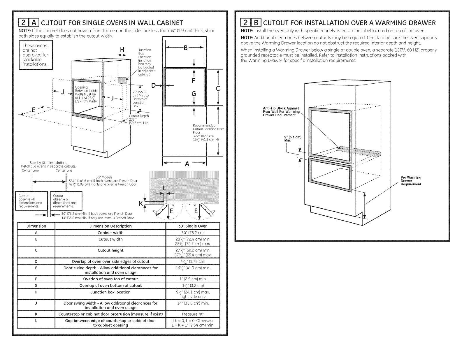
[TrA-I CUTOUT FOR SINGLE OVENS IN WALL CABINET
NOTE: If the cabinet does not have a front frame and the sides are less than sA" (1.9 cm) thick, shim
both sides equally to establish the cutout width.
These ovens
are not
approved for
stackable
installations.
!F
;I
a Junction
Box
Location
', box may
i
Ijunction
be located
_=-=-B -==-_
121BICUTOUT FOR INSTALLATION OVER A WARMING DRAWER
NOTE: Install the oven only with specific models listed on the label located on top of the oven.
NOTE: Additional clearances between cutouts may be required. Check to be sure the oven supports
above the Warming Drawer location do not obstruct the required interior depth and height.
When installing a Warming Drawer below a single or double oven, a separate 120V, 60 HZ, properly
grounded receptacle must be installed. Refer to installation instructions packed with
the Warming Drawer for specific installation requirements.
i .....
Opening
m-J
Side-by-SideInstallations
Install two ovens in separate cutouts.
CenterLine
CenterLine
BetweenInside
Walls Mustbe
atLeast287"
(72.4cm)Wi(Je
I
q 87/(148.6 cm}ifboth ovens ore FrenchDoor
P
Cutout
observe all
dimensions ond
requirements.
=====-li_l,,I-,_;.-,_.30"(76.2cm)Min.if bothovensoreFrenchDoor
Dimension Dimension Description
A Cabinet width
B Cutout width
C Cutout height
D Overlap of oven over side edges of cutout _V_" (1.75 cm)
E Door swing depth - Allow additional clearances for 16V_"{41.3 cm) min.
F Overlap of oven top of cutout 1" {2.5 cm) min.
G Overlap of oven bottom of cutout lye" (3.2 cm)
J
K
L
42_" (108 cm)if only oneovenis FrenchDoor
I
I
Cutout
observeoil
dimensionsand
requirements
14"(35.6cm)Min.if onlyone ovenisFrenchDoor
Door swing width - Allow additional clearances for
Countertop or cabinet door protrusion Imeasure if exist)
Gap between edge of countertop or cabinet door
]
', ' 22" (55.9
Ii cm}Min.to
|_ _ Bottom of
' Junction
30"Models
installation and oven usage
Junction box location
installation and oven usage
to cabinet opening
D==€
iiiiiiiiiiiiiiiiiiiiiiiiiiiiiiiiiiiiiiiiiiiiiiiiiiiiiiiiiiiiiiiiiiiiiiiiiiiiiiiiiiiiiiiiiiiiiiiiiiiiiiiiiiiiiiiiiiiiiiiiiiiiiiiiiiiiiiiiiiiiiiiiiiiiiiiiiiiiiiiiiiiiii
....ii............ii!!i i!iiiiiiiiiiiiiiiiiiiiiiiiiiiiiiiii ;,,,,,......
If K= 0, L = 0, Otherwise
L = K + 2" (2.54 cm) min.
G
C
Anti-Tip Block Against
t "
Recommended
Cutout Locationfrom
Floor
Rear Wall Per Warming
Drawer Requirement N
2" (5.1 cm)
Min.
Per Warming
Drawer
Requirement
..............................................
30" Single Oven
30" (76.2 cm)
28_/_" (72.4 cm) min.
28_" (72.7 cm) max.
27_/_" (69.2 cm) min.
27_" {69.4 cm) max.
9_/_" (24.2 cm) max.
right side only
14" (55.6 cm) min.
Measure "K"
Page 3
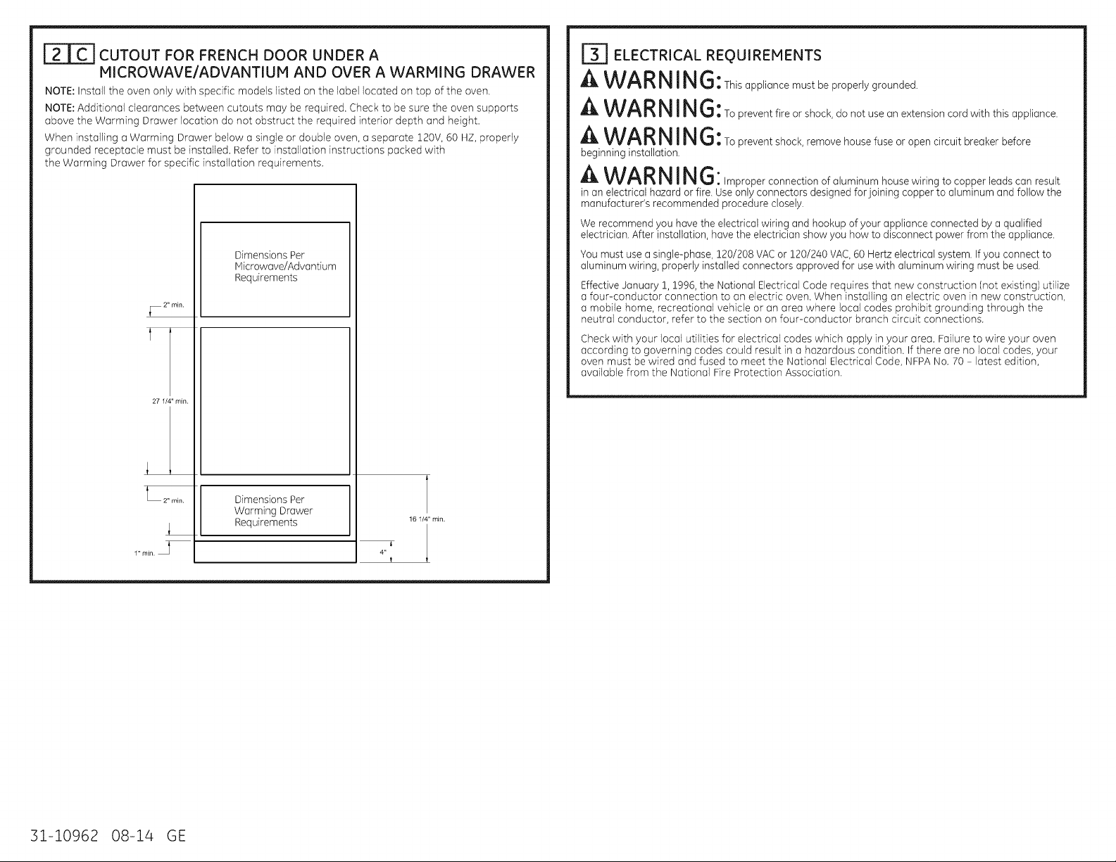
I21CICUTOUT FOR FRENCH DOOR UNDER A
!ICROWAVE/ADVANTIUM AND OVER A WARMING DRAWER
NOTE: Install the oven only with specific models listed on the label 1orated on top of the oven.
NOTE: Additional clearances between cutouts may be required. Check to be sure the oven supports
above the Warming Drawer location do not obstruct the required interior depth and height.
When installing a Warming Drawer below a single or double oven, a separate 120V, 60 HZ, properly
grounded receptacle must be installed. Refer to installation instructions packed with
the Warming Drawer for specific installation requirements.
Dimensions Per
Microwave/Advantium
Requirements
_ 2" min.
t
27 1/4" min.
ITI ELECTRICAL REQUIREMENTS
A WARNING: Th,sapp,iancemustbeproper,ygrounded.
A WAR NING:Topreventf,reorshock,donotuseanextens,oncordwithth,sapp,,ance.
A WARNING: Topreventshock,removehousefuseoropencircuitbreakerbefore
beginning installation.
A WAR N I N G [improper connection of aluminum house wiring to copper leadscan result
in an electrical hazard or fire. Useonly connectors designed forjoining copper to aluminum and follow the
manufacturer's recommended procedure closely.
We recommend you have the electrical wiring and hookup of your appliance connected by a qualified
electrician. After installation, have the electrician showyou how to disconnect power from the appliance.
You must use a single-phase, 120/208 VAC or 120/240 VAC,60 Hertzelectrical system, if you connect to
aluminum wiring, properly installed connectors approved for use with aluminum wiring must be used.
Effective January 1,1996, the National Electrical Code requires that new construction (not existing) utilize
a four-conductor connection to an electric oven. When installing an electric oven in new construction,
a mobile home, recreational vehicle or an area where 1oral codes prohibit grounding through the
neutral conductor, refer to the section on four-conductor branch circuit connections.
Check with your local utilities for electrical codes which apply in your area. Failure to wire your oven
according to governing codes could result in a hazardous condition. If there are no local codes, your
oven must be wired and fused to meet the National Electrical Code, NFPANo. 70 - latest edition,
available from the National Fire Protection Association.
_ 2" min.
i
1" min.
31-10962 08-14 GE
Dimensions Per
Warming Drawer
Requirements
161/4" min.
l
!
Page 4
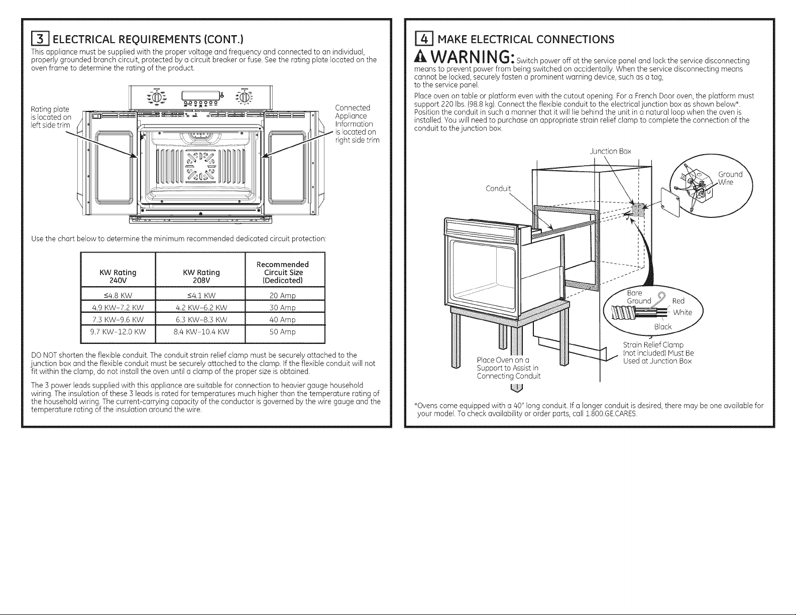
ITI ELECTRICAL REQUIREMENTS (CONT.)
This appliance must be supplied with the proper voltage and frequency and connected to an individual,
properly grounded branch circuit, protected by a circuit breaker or fuse. See the rating plate located on the
oven frame to determine the rating of the product.
Rating plate
is located on
left sidetrim
Use the chart below to determine the minimum recommended dedicated circuit protection:
Connected
Appliance
Information
right sidetrim
l_] MAKE ELECTRICAL CONNECTIONS
A WARNING:Sw,tch power off at the service panel and lock the service disconnecting
means to prevent power from being switched on accidentally. When the service disconnecting means
cannot be locked, securely fasten a prominent warning device, such as a tag,
to the service panel.
Place oven on table or platform even with the cutout opening. Fora French Door oven, the platform must
support 220 Ibs.(98.8 kg). Connect the flexible conduit to the electricaljunction box as shown below*.
Position the conduit in such a manner that itwill lie behind the unit in a natural loop when the oven is
installed. Youwill need to )urchase an appropriate strain relief clamp to complete the connection of the
conduit to thejunction box.
Junction Box
Conduit
KW Rating KW Rating Circuit Size
240V 208V (Dedicated)
<4.8 KW <4.t KW 20 Amp
4.9 KW-7.2 KW 4.2 KW-6.2 KW 30 Amp
7.3 KW-9.6 KW 6.3 KW-8.3 KW 40 Amp
9.7 KW-12.0 KW 8.4 KW-IO.4 KW 50 Amp
DO NOTshorten the flexible conduit. The conduit strain relief clamp must be securely attached to the
junction box and the flexible conduit must be securely attached to the clamp. If the flexible conduit will not
fit within the clamp, do not install the oven until a clamp of the proper size is obtained.
The 3 power leads supplied with this appliance are suitable for connection to heavier gauge household
wiring. The insulation of these 3 leads is rated for temperatures much higher than the temperature rating of
the household wiring. Thecurrent-carrying capacity of the conductor isgoverned by the wire gauge and the
temperature rating of the insulation around the wire.
Recommended
Strain ReliefClamp
PlaceOven on a
Support to Assist in
Connecting Conduit
*Ovens come equipped with a 40" long conduit. If a longer conduit isdesired, there may be one available for
your model. To checkavailability or order parts, call :]_.800.GE.CARES.
(not included) Must Be
Used at Junction Box
Page 5
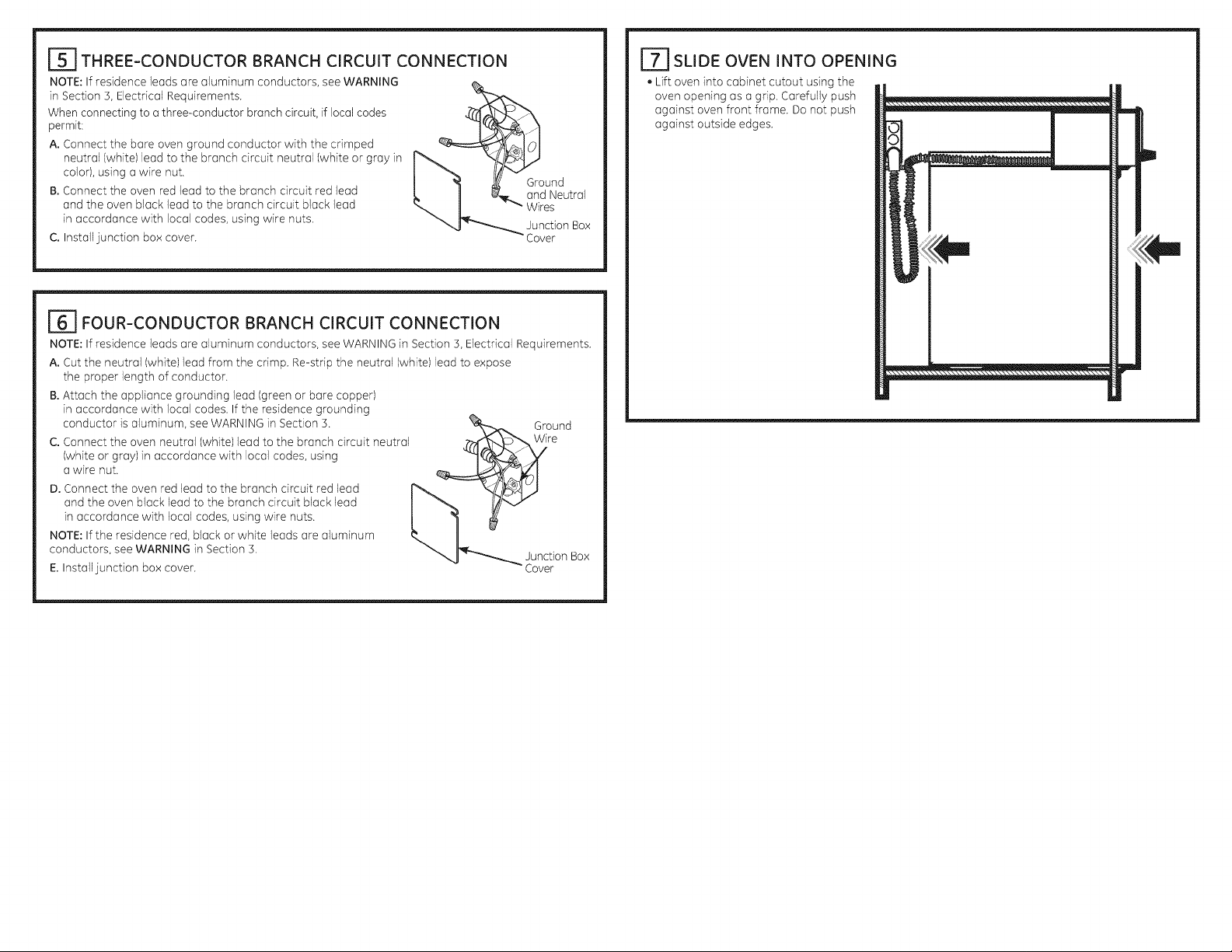
[_] THREE-CONDUCTOR BRANCH CIRCUIT CONNECTION
NOTE: If residence leads are aluminum conductors, see WARNING
in Section 3, Electrical Requirements.
When connecting to a three-conductor branch circuit, if local codes
permit:
A. Connect the bare oven ground conductor with the crimped
neutral (white)lead to the branch circuit neutral (white or gray in
color), using a wire nut.
B.Connect the oven red lead to the branch circuit red lead
and the oven black lead to the branch circuit black lead
in accordance with local codes, using wire nuts.
C. Install junction box cover.
161 FOUR-CONDUCTOR BRANCH CIRCUIT CONNECTION
NOTE: If residence leads are aluminum conductors, see WARNING in Section 3, Electrical Requirements.
A. Cut the neutral (white) lead from the crimp. Re-strip the neutral (white) lead to expose
the proper length of conductor.
B.Attach the appliance grounding lead (green or bare copper)
in accordance with local codes. If the residence grounding
conductor is aluminum, see WARNING in Section 3.
C. Connect the oven neutral (white) lead to the branch circuit neutral
(white or gray)in accordance with local codes, using
a wire nut.
D. Connect the oven red lead to the branch circuit red lead
and the oven black lead to the branch circuit black lead
in accordance with local codes, using wire nuts.
NOTE: If the residence red, black or white leads are aluminum
conductors, see WARNING in Section 3.
E.Install junction box cover.
GrOe nd
unction Box
Cover
L_] SLIDE OVEN INTO OPENING
, Lift oven into cabinet cutout using the
oven opening as a grip. Carefully push
against oven front frame. Do not push
against outside edges.
Page 6

[_] BOTTOM TRIM INSTALLATION
. Slide oven out by 2" and attach the bottom trim through its mounting holes in front vertical brace
using two trim screws provided. Bottom trim lip must be placed under flange of bottom air duct.
SWO's installation
[_] MOUNT THE OVEN
WAR NIN f'_--'_.]l®IVlounting screws must be used. Fai)ure to do so could result in the
oven falling out of the cabinet, causing serious injury.
NOTE: During oven mounting step, ensure that no damage is done to oven gasket which lines the
edge of oven cavity.
NOTE: Before drilling the pilot holes, make sure the oven is pushed as far back into the opening as it
will go and is centered.
NOTE: If the cabinet is particle board, you must use #8 × sA,,particle board screws. These may be
purchased at any hardware store.
A. Drill through the mounting holes (top and bottom) of the side trim for the #8 mounting screws
provided.
B.Secure the oven cabinet with the screws provided.
The Screws Must
Be a Minimum of
¼" (6 mm) From
the Front of the
Cutout.
Mounting
Hole
Locations
(hole locations
may vary) ....._
Exercise caution while sliding the unit back in after bottom trim installation. Installer needs to ensure
that the trim does not catch the edge of the cabinet and bend. Furthermore, the installer needs to
ensure that the cabinet itself is not damaged while the unit is slid back into position.
A -W--ARNIN--6; Do not slide oven out more than noted dimension, the unit can tip over and
fall causing serious injury & damage.
i
Page 7

_OVEN RACK GUIDE INSTALLATION
A. Locate included oven rack guide mounting hardware.
B. Placeoven rack guides on cavity wall studs with Lbracket towards back of cavity as shown.
C. Install guides using the 8 provided mounting nuts.
French doors removed for
illustration clarity only
Metal Posts to be
installed in the
rear of cavity
Oven rack
guide shown
French doors removed for
illustration clarity only
in place.
_DOOR ADJUSTMENT MECHANISM
DoorAdjustmentMechanism islocatedon boththerightand leftdoorsatthe bottom hinges.Onlythe
leftsideAdjustmentMechanism isshown inthismanual.
NOTE: Adjustthedoorsinwardonlyuntilthecentergap iseven.Over-adjustingcan damage thecenter
sealsand make thedoorsmore difficulttoopen.
A.Using9/16"socketwrench,tightenVerticalAdjustmentScrewtoadjustdoor up and loosento
adjust door down.
B.Horizontal Adjustment Screws pivot
the door about an axis. Using a 1/8"
Hex Key, loosen both screws, then
tighten appropriate screw to pivot
door. Once door is in place, verify both
screws are tightened.
EXAGGERATEDEXAMPLESFORLEFT
DOOR ADJUSTMENT
Example i: Left door low,
center gap even,
2£1£1£1£1£1£1£1£1£1£1£1£1£1£1£1£_J
Steps for adjustment:
A.Tighten left Vertical
Adjustment Screw.
B.If left door is still low, loosen
right Vertical Adjustment
Screw.
Horizontal Adjustment Screws
Vertical Adjustment Screw
Example 2: Left door low,
center gap larger at bottom.
Steps for adjustment:
A. Loosen inside Horizontal
Adjustment Screw.
B.Tighten outside Horizontal
Adjustment Screw until center
gap even.
C. If left door is still low, tighten
left Vertical Adjustment Screw.
D. Tighten inside Horizontal
Adjustment Screw.
Example 3: Left door high,
center gap larger at top.
Steps for adjustment:
A. Loosen outside Horizontal
Adjustment Screw.
B.Tighten Outside Horizontal
Adjustment Screw until center
gap even.
C. If left door is still low, tighten
Left Vertical Adjustment
Screw.
D.Tighten Inside Horizontal
Adjustment Screw.
31-10962 08-14 GE
Page 8

FINALINSTALLATIONCHECKLIST
, Check to make sure the circuit breaker is closed (RESET)or the circuit fuses are replaced.
, Be sure power is in service to the building.
, Check that all packing material and tape have been removed. Failure to remove these materials
could result in damage to the appliance once the appliance has been turned on and surfaces have
heated.
, Remove all items from inside the oven.
, Check to be sure that the mounting screws are installed and flush with the side trim
(see Section 91.
, Check that the bottom trim is installed properly (see Bottom Trim Installation).
, Ensure that air duct opening at bottom of unit is free of obstructions.
, Check that oven rack guides (if applicable) are installed correctly and oven racks function smoothly.
OPERATION CHECKLIST
, Turn on the power to the oven (refer to your Owner's Manual). Verify that the bake and broil units and
all cooking functions operate properly.
, See your Owner's Manual for the troubleshooting list.
, Be sure all of the oven controls are OFFbefore leaving the oven.
, Open the door completely and ensure that there is sufficient clearance to surrounding cabinets and
counter tops.
Page 9

Instruccionesdeinstalaci6n
HornosdeparedEmpotrablesconPuertasFrancesasde30"
_Preguntas? Llame al 1.800.GE.CARES(1.800.452.2737)ovisite GEAppliances.com
EnCanadd,ltameal 1.800.561.3344o visite www.GEApptiances.ca.
ANTES DE COMENZAR
Lea estas instrucdones par completo y con
detenimiento.
" IMPORTANTE - Guardeestasinstrucciones
pareelusadeinspectoreslocales.
" IMPORTANT -- Cumplacontodos losc6digosy
ordenanzasvigentes.
• Noteel instalador- Aseg@esede @jarestas
instruccionesconel Consumidor.
ATENCI6NINSTA_DOR:Todos10sh0mosdeparedel#ctricosdebencontarconcableadodeconexi6npermanente
{cableadodirecto)dentr0deunacajadec0nexi0nesapr0badaEnest0sproduct0sNOsepermitelaconexi6ndeitipo'enchufeyreceptdcui0"
PARA SU SEGURIDAD:
ADVERTE N CIA: Antesdecomenzar,a,nsta,ad6n,desconectela energia
del panel de servicio y bloqueelos medios de desconexi6npare evitar el accionamiento dela energia de manera
accidental. Cuando losmedios de desconexi6nde serviciono pueden bloquearse,coloque sobre
el paneldeservicio un dispositivode advertencia bienvisible,como una etiqueta.
EIhomo debe instalarsebien en un gabineteque seencuentre firmemente sujeto a laestructura de lacase.Sise
coloca pesosobre la puerta del homo, #stepuede volcarse y provocar lesiones.Nunca permita que nadiese suba,
siente,pare o cuelguede la puertodel homo.
Verifiqueque el revestimiento de los paredes,mostradores y gabinetes ubicados alrededor del homo puedan
soportar elcolor (haste200°F [93,3°C])generado por elhomo.
, Note al consumidor- Conserve estas
instrucciones pare referenda futura.
, Nivel de destreza - La instalad6n de este
aparato requiere un instalador o electridsta
ealificados.
, El instalador tiene la responsabilidad de
efectuar una instalad6n adecuada.
, La garant[a no cubre los folios del producto
provocadas par una instalaci6n incorrecta.
, Este producto s6lo se debe user en 6reas
interiores.
INFORMACI6N DE DISE
INSTALACIONESDEHORNOSIMPLECON PUERTAFRANCESA
Elhomo simple con Puerto Francesa puede ser instalado en un gabinete aparte o sobre un caj6n para
calentar y/o debajo de un Microondas/Advantium. Sinembargo, el homo simple con Puerto Francesa no
est6 permitido.
IMPORTANTE:Siempre consultelosinstruccionesdeinstalacionesindividualesenviadasconcodaproducto
parerequerimientosespecificos.
121 PREPARE LA ABERTURA
NOTA: Si el gabinete no cuenta con un fondo s61ido,
deben instalarse dos abrazaderas o gufas para
soportar el peso del horno. Pare Hornos con Puerta
Francesa, las gufas o abrazaderas deben soportar
220 Ibs (98.8 kgs).
NOTA: Si marcas, imperfecdones o la abertura
resultaran visibles sabre el homo instalado, puede
ser necesario agregar cu_as de madera bajo las
gufas y el reborde frontal hasta cub@ las marcas
o la abertura.
NOTA: Si el gabinete no cuenta con un armaz6n
frontal y los lados son menores a un grosor de sA"
(1,9 cm), coloque cu_as uniformemente sobre ambos
lados para establecer al ancho de la abertura.
Abrazaderas
adecuadas
para sostener
las guias
Gu_as de 2"x 4" (5 cm x 10 cm)
o equivalentes a nivel con
el rondo del recorte
y niveladas los
costados de I abertura
MATERIALESQUEPUEDENECESITAR
Cajade conexiones
Taponesdealambre
Abrazaderadealiviode tensi6npara conductode1/2"
HERRAMIENTAS NECESARIAS
Broca de perforadora de 1/8"y perforadora
el@ctricao de mano
Destornillador de estrella
Alicates pelacables
Llave deTubo de 9/16"
Llave Hexagonal de 1/8"
FTI QUITE LOS MATERIALES DE EMPAQUE
Noquitar los matefiales de empaque puede provocar daf_osel electrodom#stico. Quite todas los partes de
empaque del homo, bandejas y elementos de calentamiento. Quite la pelicula protectora y los etiquetas de
la puerto exterior y panel de control. Tambi#n, quite los elementos pl6sticos de los rebordes y panel, toda la
cinta que cubre el homo y lostornillos de envfo que fUanel homo a la almohadilla base.Abra la puerto del
homo yquite el material informativo y losbandejas del horno. Quite elreborde inferior de la porte superior del
horno. Secolocar6 al final del proceso de insta(aci6n. Elreborde seencuentra envuelto en forma separada y
adherido en la porte superior de la unidad.
Page 10

[T_ ABERTURA PARA HORNOS ONICOS EN UN GABIENTE DE PARED
NOTA: Si el gabinete no cuenta con un armaz6n frontal y los lades son menores a un grosor de 3/4" (1,9 cm),
coloque cutlas uniformemente sobre ambos lades para establecer al ancho de la abertura.
Estos homes
no est6n
aprobados
para
instalaciones
apilables.
i .....
de la caja de
Ubicanci6n
conexiones
_"F ', cone×iones
' ' puedehaliarse
II
!l _ady ....... tel
Laabertura _ D==i
entrelas
saredesinterna! 22"(55,9cm)
Jebeserde per F-_ ! , rain.hasta la
o menos28/_" J _ ', porteinferior
(la caja de
__ en un gabinete
_.-._B.=-_
G
_IBi ABERTURA PARA SOBRE UN
INSTALACI6N CAJ6N
CALENTADOR
NOTA: Instale el homo s61ocon los modelos especificos listados en laetiqueta ubicada
en la parte superior del homo.
NOTA: Pueden necesitarse espados adicionales entre las aberturas. Verifique que los soportes
del homo sobre la ubicaci6n de caj6n calentador no obstruyan la profundidad y altura interiores
requeridas.
Cuando instale un caj6n calentador deba]o de un homo Onico o doble, debe instalarse
un tomacorriente separado de 120V, 60 HZ con adecuada cone×i6n a tierra. Consulte
los instrucdones de instalaci6n enviadas con el caj6n calentador para requisites especfficos
de instalaci6n.
C
_ I , ', dela cajade, .-""" ] Profundfdadde(a
_--___"aber tura -23/j'
I ... -" (59,7cm}minir:no
1
1
1
t "
Ubicanci6nrecomem
dada de la abertura
desdeel piso
I_L
Instalaciones lade a lade
Instale dos homes en aberturas separadas.
Linea central
J
Abertura cumpla
contodaslas
dimensfonesy
requedmientos.
D!mensi6n Descripci6n de !a dimensi6n . Homo 6n!co de30"
A Ancho del gabinete 30" (76,2 cm)
B Ancho de Io abertura 28_/_'' (72,4 cm) min.
C Altura de Io oberturo 27_" (69,2 cm) min.
D
E
F
G
H
K
L
Lineacentral
! HHHHHHHHHHHHHHHHHHHHHHHHHHHHHHHHHHHHHHHHHHHHHHHHHHHHHHHHHHHHHHHHHHHHHHHHHHHHHHHHHHji
58X"(148,6cm) _boshomo:tie
42_" ]_08cm s s6 o unhomot one PuertoFrancesa
Abertura_cumpla |
contodaslas
dimensionesy K ....
requerimientos. I _ 7_J "-,r ,," v ['1_.
30"(62 cm)d_min siarnbosh..... ti..... PuertaF......... | .q____ /E ," ', E I \__Q
I"_;"_ 14"'3516cmderain[sis61ounh...... tienePuertoF....... _ I_ -" "'- _
Superposici6n del homo sobre los costados laterales de la abertura
Profundidad del giro de la puerta- Deje espacio adicional peru la
Superposici6n de la porte superior del homo de la abertura
Superposici6n de la parte superior del homo de la abertura
Ubicaci6n de la caja de conexiones
Ancho del giro de la puerta- Deje espacio adicional para la
Protuberancia de la mesada o de la puerta del gabinete (medida si existe)
Brecha entre el extremo de la mesada o de la puerta del gabinete y la
Modelosde30"
instalaci6n y use del homo
instalaci6n y uso del homo
abertura del gabinete
b-- A--4
28s/_'' (72,7 cm) max.
. 27_Z (69,4 cm) max_
_," (1,75 cm)
161/," (/41,3cm) min.
1" (2,5 cm) min.
11/,'' (3,2 cm)
9_" (24,1 cm) max.
solo lade derecho
14" (35,6 cm) min.
Medida "K"
Si K= O,L = O, de otra forma
L = K + 1" (2,54 cm) min.
Ubicacibn
recomendada
de la abertura
desde el pise
21 5/8" (54 9 cm)
Bioque anti-ve|caduras
contra |a pared trasera
segun requisite del
cajbn caientador
2" (5,1 cm)
mln,
lOS requisites
5n caJentador
Page 11

[_]_] ENCASTRE PARA PUERTA FRANCESA BAJO UN MICROONDAS/
ADVANTIUM Y SABRE UN CAJaN PARA CALENTAR
A. Co]oque un riel con pedestal en cada rodadura del gabinete o centrado en el lado opuesto de la
parte inferior del gabinete s6lido nivelado con el lateral de la obertura del gobinete. Ubique coda riel
de modo que la porte frontal de los mismos se encuentre detr6s del 1adofrontal de la oberturo del
gobinete.
B.Realice ogujeros de pruebo y odjunte los deles o la rododuro o o la porte inferior del gobinete con el
equipo provisto.
Dimensiones de Acuerdo
con los Requisitos para
Microondos/Advontium
27 1/4" min.
[_] REQUISiTOS ELE_CTRICOS
A ADVERTENCIA: Esteepuroto debe contur con uno edecuedu conexi6n o tierre.
A ADVERTENCIA: Poro prevenir un incendio o descerge el_ctrico, no utilice un cable
de extensi6n con este opereta.
A ADVERTENCIA: Poro prevenir uno descorge el_ctrice, quite el fusible o ebru el
interruptor dedrcuitas ontes de comenzor Ioinsteleci6n.
A ADVERTEil CIA:Unoconexi6n inodecuude de cebleudo dom_stico de eluminio con
cables de cobre puede generer un peligra el_ctrico a un incendia. S61ause canectores disehedas pore unir
cobre can eluminio y sige ol pie de Io letro el procedimiento recomendeda del febriconte.
Recomendmmosque un electricisto colificodo conecte el cubleado el_ctrico de su mpuruto. Despu#s
de Io instoloci6n, solicite ol electricisto que le indique c6mo desconector Io energio del oporoto.
Usted debe usar un sistema el@ctricade fase 0nica de 120/208 VACo 120/240 VACde 60 hercios.Si tiene
una conexi6n con cableado de aluminio, deben utilizarse conectores adecuadamente instalados para
utilizar con cableado de aluminio.
Vigente desde el Z de enero de 1996, el C6digo El@ctricoNacional requiere que las nuevas construcciones
(no existentes) utilicen una conexi6n de cuatro conductores a un homo el@ctrico. Cuando instale un homo
el@ctricoen una construcci6n nueva, una cosa rodante, un vehiculo recreativo o un 6rea donde los c6digos
locales prohiben laconexi6n o tierra a troves de un conductor neutral, consulte la secci6n sabre conexiones
en circuito derivado de cuatro conductores.
Consulte alas empresas de servicio pOblico sabre los c6digos el@ctricosque se aplican en su 6rea. No
realizor el cableado de su homo de acuerdo con losc6digos vigentes puede provocar una situaci6n
peligrosa. Si no existen c6digos locales, el cableado y fusibles de su homo deben cumplir con el C6digo
El@ctricoNacional, NFPANO70, 01timaedici6n, disponible en National Fire Protection Association (Asociaci6n
Nacional de Protecci6n contra Incendios).
1" rain.
31-10962 08-14 GE
Dimensiones de ocuerdo
con los Requisitosdel
Coj6n para Colenter
16 1/4" min.
1
4"
T
Page 12

[_ REQUiSITOSELI_CTRICOS(CONT.)
Esteaparato debe recJbJrel voltaje y frecuencJa adecuados, ydebe conectarse a un cJrcuJtoderJvado
individual con adecuada cone×i6n a tierra, protegido pot un interruptor de circuitos o fusible. Ver la placa de
clasificaci6n ubicada en el armaz6n del homo para determinar la dasificaci6n del producto.
Laplaca de [l
calificad6n
sobre el _-- Electrodom6stico
borde lateral Conectado est6
izquierdo h ubicada sobre el
Hest6 ubicada LaInformad6n del
'111° :_,_ ° !jill,
=o_ooooo
@
H
breborde lateral
derecho
_-_ REALICE LAS CONEXIONES
ELI_CTRICAS
_, ADVE RT E N Cl A: Desconectelaenergiadelpane,deservic,oyb,oqueelosmed_os
de desconexi6n para evitar el accionamiento de laenergia de manera accidentak Cuando losmedios
de desconexi6n de servicio no pueden bloquearse, coloque sobre elpanel de servicio un dispositivo de
advertencia bien visible, como una etiqueta.
Coloque el homo sobre una mesa o plataforma en forma nivelada con la abertura. En un homo con
Puerta Francesa, la plataforma debe soportar 220 Ibs.(98,8 kg).Conecte el conducto flexible a lacaja de
conexiones el@ctricacomo se indica abajo*. Posicione el conducto de modo tal que se apoye detr6s de la
unidad en un circulo natural cuando el homo sea instalado. Tendr6 que comprar una abrazadera para alivio
de tensi6n apropiada para completar la conexi6n del conducto a la caja de conexiones.
Caja de conexiones
[ ................ !
Utilice la tabla de abajo para determinar la protecci6n de circuito dedicado minima recomendada:
Clasificaci6n Tama6o de circuito
de KW Clasificaci6n de KW recomendado
240V 208V {dedicado)
-<4,8 KW -<4,1 KW 20 Amp
4,9 KW=7,2 KW 4,2 KW=6,2 KW 30 Amp
7,3 KW=9,6 KW 6,3 KW=8,3 KW 40 Amp
9,7 KW=12,0 KW 8,4 KW=IO,4 KW 50 Amp
NO acorte el conducto flexible. Laabrazadera del alivio de tensi6n del conducto debe estar bien sujeta a la
caja de conexiones y el conducto flexible debe estar bien sujeto a la abrazadera. Siel conducto flexible no
entra dentro de la abrazadera, no instale el homo hasta obtener una abrazadera del tama_o adecuado.
Los 3 cables de energia suministrados con este aparato son adecuados para conexiones con cableados
dom@sticosde calibre mayores. La aislaci6n de estos 3 cables est6 clasificada a temperaturas mucho m6s
elevadas que la clasificaci6n del cableado dom@stico.La capacidad
de transmitir corriente del conductor est6 determinada por el calibre del cable y la clasificaci6n
de temperatura de la aislaci6n alrededor del cable.
Conducto
La abrazadera del alivio
Coloque el homo
en un soporte para
ayudar a la conexi6n del
conducto
*Loshornosvienenequipadoscon unconductode 40"deIongitud.Sideseaunconductom6slargo,puedehaberuno
disponibleparasumodelo.Paraverificarladisponibilidado soticitarpiezas,Ilameal1.800.GE.CARES.
de tensi6n (no incluido)
debe usarse en la caja de
conexiones
Page 13

_-_ CONE×I6N DECIRCUITO DERIVADO DETRESCONDUCTORES
NOTA:Silos cables dom_sticos son conductores deaJuminio,
ver la ADVERTENCIAde la secd6n 3, IRequisitosel6ctricos.
Cuando conecte un circuito derivado de tres conductores,
si Io permiten losc6digos locales:
A. Conecte el conductor a tierra del homo con elcable neutral (blanco)
en rizoal neutral delcircuito derivado (blanco o gris)utilizando un
tap6n de alambre.
B.Conecte el cable rojo del homo alcable rojo del circuito derivado y el
cable negro del homo al cable negro delcircuito derivado de acuerdo
con losc6digos locales,utilizando tapones dealambre.
C.Instale la tapa de lacaja decone×iones.
_bles a
CONEXI6N DE CIRCUITO DERIVADO DE CUATRO
CONDUCTORES
NOTA: Si los cables dom6sticos son conductores de aluminio, vet la ADVERTENCIA
de la secd6n 5, Requisitos el@ctricos.
A. Carte el cable neutral (blanco) del conector de engarce.
Pele el cable neutral (blanco) para e×poner la Iongitud correcta
del conductor.
B.Conecte el cable a tierra del artefacto (verde o cobre)
de acuerdo con los c6digos locales. Si el conductor a tierra de la
residencia es de aluminio, ver ADVEIRTENCIAde la secci6n 3.
C. Conecte el cable neutral (blanco) del homo con el neutral
de circuito derivado (blanco o gris) de acuerdo con c6digos
locales, utilizando un tap6n de alambre.
D. Conecte el cable rojo del homo al cable rojo del circuito derivado
y el cable negro del homo al cable negro del circuito derivado de
acuerdo con los c6digos locales, utilizando tapones de alambre.
NOTA: Si los cables rajas, negros o blancos son conductores de
aluminio, vet ADVEIRTENCIAde la secci6n 3.
E.Ilnstale la tapa de la caja de cone×iones.
cone×iones
Cabrlea
Tapade
la cajade
cone×iones
| DESLICE EL HORNO DENTRO DE LA ABERTURA
oLevante el homo dentro
de la abertura del gabinete utilizando
el homo abierto coma agarre. Con
cuidado empuje contra el armaz6n
frontal del homo. No presione sabre
los bordes e×ternos.
Page 14

_ INSTALACI6N DEL REBORDE INFERIOR
, Una vez instalado el horno, adjunte el borde inferior a trav6s de sus agujeros de montaje frente aJ
soporte vertical, utilizando los dos tornillos con cabeza recortada provistos. Ellabio de la cubierta
inferior deber6 set ubicado debajo de Jabrida de Japarte inferior del conducto de aire.
Instalaciones SWO
[_ INSTALE EL HORNO
A ADV ERTENCIA: Deben utilizarse tornillos de montaje. Si no Iohace, el
homo puede caer del gabinete, Io que provocar{a una lesi6n grave.
NOTA: Durante el montaje del homo, aseg_rese de que no haya da_os sobre lajunta del homo, que
ali_a el e×tremo de la cavidad del homo.
NOTA: Antes de perforar los orifidos piloto, asegL3resede que el homo se encuentre
en la posici6n final de la abertura y centrado.
NOTA: Siel gabinete es de placa de partTculas, deben utiFzarse tornillos #8 × s4,,para dicho material.
_stos pueden adquirirse en cualquier ferreteria.
A. Perfore a trav6s de los orificios de montaje (superiores e inferiores) del reborde lateral para los
tornillos de montaje #8 provistos.
B.Asegure el gabinete del homo con los tornillos provistos.
Tenga cuidado al deslizar Jaunidad nuevamente hacia adentro, luego de la instaJaci6n en el reborde
inferior. Elinstalador se debe asegurar de que el reborde no atrape el extrerno del gabinete y se doble.
Adem@s,el instalador se debe asegurar de que el gabinete mismo no sea da_ado mientras la unidad
es deslizada nuevamente hasta su posici6n.
A ADVERTENCIA: No deslice el horno hacia afuera mds alld de ladimensi6n
establecida; la unidad se podr@volcar y caer generando lesionesy da_os graves.
Page 15

GUJA DE INSTALACION DE LA ESTANTERiA DEL HORNO (Sl
CORRESPONDE)
A. Ubique el equipo de montaje de la gufa del homo induida.
B. Posidone el conducto de modo tal que se apoye detr6s de la unidad en un efreulo natural euando el
homo sea instalado.
C. Instale las gufas usando las 8 tuercas de montaje provistas.
Los Pivotes Met61icos
se deben instalar en
la parte trasera de la
cavidad
_ MECANISMO DE AJUSTE DE LA PUERTA
ElMecanismo de Ajuste de la Puerta se encuentra ubicado tanto en la puerta derecha coma en la izquierda,
en las bisagras inferiores. $61oel lado izquierdo del Mecanismo de Ajuste es mostrado en estemanual.
NOTA: Ajuste las puertas hacia adentro, s61ohasta que la brecha central est6 pareja. Un ajuste
excesivo puede daflar los cierres herm6ticos centrales y dificultar la apertura de las puertas.
A. Utilizando una Ilave de tuba de 9/16", ajuste el Tornillo de Ajuste Vertical, a fin de ajustar la puerta
hacia arriba y ajustar la misma hacia abajo.
B.Los Tornillos de Ajuste Horizontal
hacen que la puerta pivote en torno a
un eje. UtiFzando una Llave Hexagonal
de 1/8", afloje ambos tornillos, y
luego ajuste el tornillo adecuado
para pivotar la puerta. Una vez que
la puerta est6 colocada, verifique que
ambos tornillos est6n ajustados.
EJEMPLOSEXAGERADOSDEL AJUSTE DELA PUERTA IZQUIERDA
Ejemplo i: Puerta izquierda Ejemplo 2: Puerta izquierda
baja, brecha central pareja, baja, brecha central m6s
Tornillos de Ajuste Horizontal
Tornillo de Ajuste Horizontal
grande en la parte inferior.
F '
t JJ _ Ji
]
Ejemplo 3: Puerta izquierda
alta, brecha central m6s
grande en la parte superior.
_e212__o ......
_% i ;i [ i i"
i i liil
i [i i'_i
31-10962 08-14 GE
La gufa del
estante del
homo se
muestra en
su posici6n.
Pasos para el ajuste:
A.Ajuste el Tornillo de Ajuste
Vertical.
B.Si la puerta izquierda a0n
est6 baja, afloje el Tornillo de
Ajuste Vertical derecho.
Pasos para el ajuste:
A. Afloje la parte interna del
Tornillo de Ajuste Horizontal.
B.Ajuste el Tornillo de Ajuste
Horizontal externo hasta que
la brecha central est6 pareja.
C. Si la puerta izquierda a0n
est6 baja, ajuste el Tornillo de
Ajuste Vertical izquierdo.
D. Ajuste el Tornillo de Ajuste
Horizontal intemo.
Pasos para el ajuste:
A. Afloje elTornillo de Ajuste
Horizontal externo.
B.Ajuste el Tornillo de Ajuste
Horizontal externo basra que
la brecha central est6 pareja.
C. Si la puerta izquierda a0n
est6 baja, ajuste el Tornillo de
Ajuste Vertical izquierdo.
D. Ajuste el Tornillo de Ajuste
Horizontal intemo.
Page 16

_ LISTADECONTROLFINALDELAINSTALACI6N
, Verifique que el (nterruptor de circuitos se encuentre cerrado (RESET)o que los fusiUes del circuito
se hayan reemplazado.
, AsegOrese de que haya suministro el6ctrico en el edificio.
. Controle que se haya quitado todo el material de empaque y la cinta adhesiva. No quitar estos
materiales puede provocar daflos al electrodom6stico una vez que el aparato se haya encendido y
las superficies se hayan calentado.
, Quite todos los elementos ubicados dentro del homo.
, AsegOrese de que los tornillos de montaje se encuentren instalados y nivelados con el reborde
lateral (ver secci6n 9).
, Verifique que el reborde inferior est6 bien instalado (consulte sobre la Instalaci6n del Reborde Inferior).
, Aseg_rese de que la abertura inferior del conducto de aire de la unidad est6 libre de obstrucciones.
. Controle que las guias de los estantes del horno (sicorresponde) est6n instaladas de forma correcta
y que los estantes del homo funcionen de forma fluida.
LISTA DE CONTROL DE FUNCIONAMIENTO
, Accione la energTadel horno (consulte el Manual del propietario). Verifique que las unidades
de horneado y asado y que todas las funciones de cocci6n operen bien.
Vet el Manual del propietario para la lista de detecci6n y soluci6n de problemas.
Aseg_rese de que todos los controles del homo se encuentren en OFF(apagado) antes
de dejar el homo.
Abra la puerta completamente y aseg_rese de que haya suficiente espacio alrededor de los
gabinetes y las mesadas.
 Loading...