

Page 1
GE Healthcare
HISTORY
AUTO CYCLE
MAP/Cuff
BATTERY OK
BATTERY LOW
CHARGING
Pul se Rat e
Temperature
Sp O
Silence
Alarms
Menu
Cycle
History
To clear hold
2 seconds
On / Off
Print
C
F
Inflate/Stop
HIGH
HIGH
LOW
LOW
Diastolic
Syst ol ic
HIGH
LOW
HIGH
LOW
ALARM VOLUME
PULSE VOLUME
INFLATE PRESSURE
NEONATE
ADULT
CARESCAPE
V100 Vital Signs Monitor
Operator’s Manual
Software Version R1.5
TM
CARESCAPE V100 Vital Signs Monitor
English
2037107-003 (CD)
2048724-001A (paper)
© 2010 General Electric Company.
All rights reserved.
Page 2

NOTE: The information in this manual applies to CARESCAPE V100 Vital Signs Monitor software version R1.5. Due to
continuing product innovation, specifications in this manual are subject to change without notice.
NOTE: For technical documentation purposes, the abbreviation GE is used for the legal entity name, GE Medical Systems
Information Technologies, Inc.
Listed below are GE Medical Systems Information Technologies, Inc. trademarks. All other trademarks contained herein are
the property of their respective owners.
Ohmeda Oximetry and other trademarks (OxyTip+, PI
, TruSat, TruSignal, TruTrak+) are the property of GE Medical Systems
r
Information Technologies, Inc., a division of General Electric Corporation. All other product and company names are the
property of their respective owners.
CARESCAPE, CRITIKON, DINAMAP, DURA-CUF, SOFT-CUF Blood Pressure Cuffs, and SuperSTAT are trademarks of GE
Medical Systems Information Technologies, Inc.
Turbo Temp™, Alaris
®
Tri-Site, and IVAC are trademarks of CareFusion Corporation.
Exergen and TAT-5000 are trademarks of Exergen Corporation.
®
is a trademark of Surgikos, Inc.
Cidex
Betadine
®
is a trademark of Purdue-Frederick.
Masimo SET, LNOP, and LNCS are trademarks of Masimo Corporation. Possession or purchase of this device does not
convey any express or implied license to use the device with replacement parts which would, alone, or in combination with
this device, fall within the scope of one or more of the patents relating to the device.
Nellcor, OxiMax, C-LOCK and SatSeconds are trademarks of Nellcor Puritan Bennett.
T-2 CARESCAPE V100 Vital Signs Monitor 2048723-001A
19 April 2010
Page 3

Contents
1 Introduction . . . . . . . . . . . . . . . . . . . . . . 1-1
About this device . . . . . . . . . . . . . . . . . . . . . . . . . . . . . . . . . . . . . . . . . . . . . . . . 1-2
Indications for use . . . . . . . . . . . . . . . . . . . . . . . . . . . . . . . . . . . . . . . . . . . . . . 1-2
Safety message signal words . . . . . . . . . . . . . . . . . . . . . . . . . . . . . . . . . . . . . 1-3
Contraindications . . . . . . . . . . . . . . . . . . . . . . . . . . . . . . . . . . . . . . . . . . . . . . . 1-3
Product compliance . . . . . . . . . . . . . . . . . . . . . . . . . . . . . . . . . . . . . . . . . . . . . 1-6
CARESCAPE V100 vital signs monitor . . . . . . . . . . . . . . . . . . . . . . . . . . . . . . . .1-6
Exergen temporal scanner . . . . . . . . . . . . . . . . . . . . . . . . . . . . . . . . . . . . . . . . .1-8
Symbols . . . . . . . . . . . . . . . . . . . . . . . . . . . . . . . . . . . . . . . . . . . . . . . . . . . . . . . . 1-8
CARESCAPE V100 vital signs monitor . . . . . . . . . . . . . . . . . . . . . . . . . . . . . . . .1-8
Exergen temporal scanner . . . . . . . . . . . . . . . . . . . . . . . . . . . . . . . . . . . . . . . 1-11
About this manual . . . . . . . . . . . . . . . . . . . . . . . . . . . . . . . . . . . . . . . . . . . . . 1-11
Printed copies of this manual . . . . . . . . . . . . . . . . . . . . . . . . . . . . . . . . . . . . . 1-11
Conventions used in this manual . . . . . . . . . . . . . . . . . . . . . . . . . . . . . . . . . . 1-12
Revision history . . . . . . . . . . . . . . . . . . . . . . . . . . . . . . . . . . . . . . . . . . . . . . . . . . 1-12
2 Getting started . . . . . . . . . . . . . . . . . . . 2-1
Unpacking the monitor and accessories . . . . . . . . . . . . . . . . . . . . . . . . . . . 2-2
Setting up NIBP connections . . . . . . . . . . . . . . . . . . . . . . . . . . . . . . . . . . . . . 2-2
Setting up SpO2 connections . . . . . . . . . . . . . . . . . . . . . . . . . . . . . . . . . . . . . 2-3
Setting up temperature connections . . . . . . . . . . . . . . . . . . . . . . . . . . . . . . 2-4
Alaris . . . . . . . . . . . . . . . . . . . . . . . . . . . . . . . . . . . . . . . . . . . . . . . . . . . . . . . . . . . . . .2-4
Exergen . . . . . . . . . . . . . . . . . . . . . . . . . . . . . . . . . . . . . . . . . . . . . . . . . . . . . . . . . . .2-4
Setting up the printer (installing the paper) . . . . . . . . . . . . . . . . . . . . . . . . 2-5
Power sources . . . . . . . . . . . . . . . . . . . . . . . . . . . . . . . . . . . . . . . . . . . . . . . . . . 2-5
Turning the monitor on and off . . . . . . . . . . . . . . . . . . . . . . . . . . . . . . . . . . . 2-6
Automatic shutdown . . . . . . . . . . . . . . . . . . . . . . . . . . . . . . . . . . . . . . . . . . . . . . .2-7
Procedure for testing alarms . . . . . . . . . . . . . . . . . . . . . . . . . . . . . . . . . . . . . 2-7
Configuration mode settings . . . . . . . . . . . . . . . . . . . . . . . . . . . . . . . . . . . . . 2-7
Entering configuration mode . . . . . . . . . . . . . . . . . . . . . . . . . . . . . . . . . . . . . . .2-8
2048723-001A CARESCAPE V100 Vital Signs Monitor i
Page 4

Configuring the default vital sign alarm limits . . . . . . . . . . . . . . . . . . . . . . 2-10
Setting the date and time . . . . . . . . . . . . . . . . . . . . . . . . . . . . . . . . . . . . . . . . . 2-11
SpO2 configuration settings . . . . . . . . . . . . . . . . . . . . . . . . . . . . . . . . . . . . . . 2-12
Temperature hardware configuration settings . . . . . . . . . . . . . . . . . . . . . 2-13
Advanced configuration mode . . . . . . . . . . . . . . . . . . . . . . . . . . . . . . . . . . . 2-15
Entering advanced configuration mode . . . . . . . . . . . . . . . . . . . . . . . . . . . 2-15
Printing the failure alarm history . . . . . . . . . . . . . . . . . . . . . . . . . . . . . . . . . . 2-15
3 Product overview . . . . . . . . . . . . . . . . . 3-1
Buttons . . . . . . . . . . . . . . . . . . . . . . . . . . . . . . . . . . . . . . . . . . . . . . . . . . . . . . . . 3-2
Front panel . . . . . . . . . . . . . . . . . . . . . . . . . . . . . . . . . . . . . . . . . . . . . . . . . . . . . 3-3
Rear panel . . . . . . . . . . . . . . . . . . . . . . . . . . . . . . . . . . . . . . . . . . . . . . . . . . . . . . 3-5
Right-side panel . . . . . . . . . . . . . . . . . . . . . . . . . . . . . . . . . . . . . . . . . . . . . . . . 3-6
Windows . . . . . . . . . . . . . . . . . . . . . . . . . . . . . . . . . . . . . . . . . . . . . . . . . . . . . . . 3-6
Indicators . . . . . . . . . . . . . . . . . . . . . . . . . . . . . . . . . . . . . . . . . . . . . . . . . . . . . . 3-6
Operating (system) modes . . . . . . . . . . . . . . . . . . . . . . . . . . . . . . . . . . . . . . . 3-7
Clinical mode . . . . . . . . . . . . . . . . . . . . . . . . . . . . . . . . . . . . . . . . . . . . . . . . . . . . . 3-7
Configuration mode . . . . . . . . . . . . . . . . . . . . . . . . . . . . . . . . . . . . . . . . . . . . . . . 3-7
Advanced configuration mode . . . . . . . . . . . . . . . . . . . . . . . . . . . . . . . . . . . . . 3-8
Service mode . . . . . . . . . . . . . . . . . . . . . . . . . . . . . . . . . . . . . . . . . . . . . . . . . . . . . 3-8
Battery low shutdown . . . . . . . . . . . . . . . . . . . . . . . . . . . . . . . . . . . . . . . . . . . . . 3-8
System failure . . . . . . . . . . . . . . . . . . . . . . . . . . . . . . . . . . . . . . . . . . . . . . . . . . . . . 3-9
User modes . . . . . . . . . . . . . . . . . . . . . . . . . . . . . . . . . . . . . . . . . . . . . . . . . . . . . 3-9
Menu mode . . . . . . . . . . . . . . . . . . . . . . . . . . . . . . . . . . . . . . . . . . . . . . . . . . . . . . . 3-9
Cycle mode . . . . . . . . . . . . . . . . . . . . . . . . . . . . . . . . . . . . . . . . . . . . . . . . . . . . . . 3-10
Limit adjustment mode . . . . . . . . . . . . . . . . . . . . . . . . . . . . . . . . . . . . . . . . . . . 3-10
History mode . . . . . . . . . . . . . . . . . . . . . . . . . . . . . . . . . . . . . . . . . . . . . . . . . . . . 3-11
Sounds . . . . . . . . . . . . . . . . . . . . . . . . . . . . . . . . . . . . . . . . . . . . . . . . . . . . . . . . 3-11
Start-up sound . . . . . . . . . . . . . . . . . . . . . . . . . . . . . . . . . . . . . . . . . . . . . . . . . . . 3-11
User interaction sounds . . . . . . . . . . . . . . . . . . . . . . . . . . . . . . . . . . . . . . . . . . 3-11
Alarm sounds . . . . . . . . . . . . . . . . . . . . . . . . . . . . . . . . . . . . . . . . . . . . . . . . . . . . 3-12
Battery low shutdown and system failure sounds . . . . . . . . . . . . . . . . . . 3-12
Battery charger sounds . . . . . . . . . . . . . . . . . . . . . . . . . . . . . . . . . . . . . . . . . . 3-12
Power sources . . . . . . . . . . . . . . . . . . . . . . . . . . . . . . . . . . . . . . . . . . . . . . . . . 3-13
Specifications . . . . . . . . . . . . . . . . . . . . . . . . . . . . . . . . . . . . . . . . . . . . . . . . . . 3-13
ii CARESCAPE V100 Vital Signs Monitor 2048723-001A
Page 5

4 Printer . . . . . . . . . . . . . . . . . . . . . . . . . . . 4-1
Description . . . . . . . . . . . . . . . . . . . . . . . . . . . . . . . . . . . . . . . . . . . . . . . . . . . . . 4-2
Installing the paper . . . . . . . . . . . . . . . . . . . . . . . . . . . . . . . . . . . . . . . . . . . . . 4-2
Print button . . . . . . . . . . . . . . . . . . . . . . . . . . . . . . . . . . . . . . . . . . . . . . . . . . . . 4-2
Printouts . . . . . . . . . . . . . . . . . . . . . . . . . . . . . . . . . . . . . . . . . . . . . . . . . . . . . . . 4-3
Current (real time) . . . . . . . . . . . . . . . . . . . . . . . . . . . . . . . . . . . . . . . . . . . . . . . . . .4-3
Clinical history . . . . . . . . . . . . . . . . . . . . . . . . . . . . . . . . . . . . . . . . . . . . . . . . . . . . .4-4
Failure alarm history . . . . . . . . . . . . . . . . . . . . . . . . . . . . . . . . . . . . . . . . . . . . . . .4-4
Paper storage . . . . . . . . . . . . . . . . . . . . . . . . . . . . . . . . . . . . . . . . . . . . . . . . . . 4-4
Alarms . . . . . . . . . . . . . . . . . . . . . . . . . . . . . . . . . . . . . . . . . . . . . . . . . . . . . . . . . 4-5
Specifications . . . . . . . . . . . . . . . . . . . . . . . . . . . . . . . . . . . . . . . . . . . . . . . . . . . 4-5
5 Alarms . . . . . . . . . . . . . . . . . . . . . . . . . . . 5-1
Description . . . . . . . . . . . . . . . . . . . . . . . . . . . . . . . . . . . . . . . . . . . . . . . . . . . . . 5-2
Alarm conditions . . . . . . . . . . . . . . . . . . . . . . . . . . . . . . . . . . . . . . . . . . . . . . . . 5-2
Physiological alarm conditions . . . . . . . . . . . . . . . . . . . . . . . . . . . . . . . . . . . . . .5-2
Technical alarm conditions . . . . . . . . . . . . . . . . . . . . . . . . . . . . . . . . . . . . . . . . .5-3
System failure alarm conditions . . . . . . . . . . . . . . . . . . . . . . . . . . . . . . . . . . . .5-4
Alarm modes . . . . . . . . . . . . . . . . . . . . . . . . . . . . . . . . . . . . . . . . . . . . . . . . . . . 5-4
IEC alarm mode . . . . . . . . . . . . . . . . . . . . . . . . . . . . . . . . . . . . . . . . . . . . . . . . . . . .5-4
Legacy alarm mode . . . . . . . . . . . . . . . . . . . . . . . . . . . . . . . . . . . . . . . . . . . . . . . .5-4
Alarm signals . . . . . . . . . . . . . . . . . . . . . . . . . . . . . . . . . . . . . . . . . . . . . . . . . . . 5-5
Audible alarm signals . . . . . . . . . . . . . . . . . . . . . . . . . . . . . . . . . . . . . . . . . . . . . .5-5
Visual alarm signals . . . . . . . . . . . . . . . . . . . . . . . . . . . . . . . . . . . . . . . . . . . . . . . .5-5
Silencing an alarm . . . . . . . . . . . . . . . . . . . . . . . . . . . . . . . . . . . . . . . . . . . . . . 5-6
Acknowledging an alarm . . . . . . . . . . . . . . . . . . . . . . . . . . . . . . . . . . . . . . . . . 5-7
Adjusting vital sign alarm limits . . . . . . . . . . . . . . . . . . . . . . . . . . . . . . . . . . 5-7
Adjusting the alarm volume . . . . . . . . . . . . . . . . . . . . . . . . . . . . . . . . . . . . . . 5-8
Alarms and priorities . . . . . . . . . . . . . . . . . . . . . . . . . . . . . . . . . . . . . . . . . . . . 5-9
Specifications . . . . . . . . . . . . . . . . . . . . . . . . . . . . . . . . . . . . . . . . . . . . . . . . . . 5-12
Factory default . . . . . . . . . . . . . . . . . . . . . . . . . . . . . . . . . . . . . . . . . . . . . . . . 5-12
2048723-001A CARESCAPE V100 Vital Signs Monitor iii
Page 6

6 History . . . . . . . . . . . . . . . . . . . . . . . . . . . 6-1
Description . . . . . . . . . . . . . . . . . . . . . . . . . . . . . . . . . . . . . . . . . . . . . . . . . . . . . 6-2
Buttons associated with history . . . . . . . . . . . . . . . . . . . . . . . . . . . . . . . . . . 6-3
Erasing stored history . . . . . . . . . . . . . . . . . . . . . . . . . . . . . . . . . . . . . . . . . . . . . 6-3
Windows associated with history . . . . . . . . . . . . . . . . . . . . . . . . . . . . . . . . . 6-3
Indicators associated with history . . . . . . . . . . . . . . . . . . . . . . . . . . . . . . . . 6-3
7 NIBP . . . . . . . . . . . . . . . . . . . . . . . . . . . . . 7-1
Description . . . . . . . . . . . . . . . . . . . . . . . . . . . . . . . . . . . . . . . . . . . . . . . . . . . . . 7-2
What is the difference between intra-arterial and auscultatory
methods? . . . . . . . . . . . . . . . . . . . . . . . . . . . . . . . . . . . . . . . . . . . . . . . . . . . . . . . . . 7-3
Buttons associated with NIBP . . . . . . . . . . . . . . . . . . . . . . . . . . . . . . . . . . . . 7-6
Inflate/Stop button . . . . . . . . . . . . . . . . . . . . . . . . . . . . . . . . . . . . . . . . . . . . . . . . 7-6
Cycle button . . . . . . . . . . . . . . . . . . . . . . . . . . . . . . . . . . . . . . . . . . . . . . . . . . . . . . 7-6
Windows associated with NIBP . . . . . . . . . . . . . . . . . . . . . . . . . . . . . . . . . . . 7-6
Indicators associated with NIBP . . . . . . . . . . . . . . . . . . . . . . . . . . . . . . . . . . 7-7
NIBP modes of operation . . . . . . . . . . . . . . . . . . . . . . . . . . . . . . . . . . . . . . . . . 7-7
Manual NIBP determinations . . . . . . . . . . . . . . . . . . . . . . . . . . . . . . . . . . . . . . . 7-8
Auto cycle determinations . . . . . . . . . . . . . . . . . . . . . . . . . . . . . . . . . . . . . . . . . 7-8
Stat NIBP determinations . . . . . . . . . . . . . . . . . . . . . . . . . . . . . . . . . . . . . . . . . . 7-9
User settings . . . . . . . . . . . . . . . . . . . . . . . . . . . . . . . . . . . . . . . . . . . . . . . . . . . 7-9
Mode settings . . . . . . . . . . . . . . . . . . . . . . . . . . . . . . . . . . . . . . . . . . . . . . . . . . . . . 7-9
Limit settings . . . . . . . . . . . . . . . . . . . . . . . . . . . . . . . . . . . . . . . . . . . . . . . . . . . . 7-10
Menu settings . . . . . . . . . . . . . . . . . . . . . . . . . . . . . . . . . . . . . . . . . . . . . . . . . . 7-10
Sounds associated with NIBP . . . . . . . . . . . . . . . . . . . . . . . . . . . . . . . . . . . . 7-11
Procedures . . . . . . . . . . . . . . . . . . . . . . . . . . . . . . . . . . . . . . . . . . . . . . . . . . . . 7-11
Checking the monitor’s NIBP technology configuration setting . . . . . 7-11
Taking NIBP measurements . . . . . . . . . . . . . . . . . . . . . . . . . . . . . . . . . . . . . . 7-12
What to do when taking NIBPs on different patients . . . . . . . . . . . . . . . 7-14
Alarms . . . . . . . . . . . . . . . . . . . . . . . . . . . . . . . . . . . . . . . . . . . . . . . . . . . . . . . . 7-14
Specifications . . . . . . . . . . . . . . . . . . . . . . . . . . . . . . . . . . . . . . . . . . . . . . . . . . 7-15
Factory defaults . . . . . . . . . . . . . . . . . . . . . . . . . . . . . . . . . . . . . . . . . . . . . . . . . . 7-16
GE Medical Systems Information Technologies, Inc. patents . . . . . . . . . 7-16
iv CARESCAPE V100 Vital Signs Monitor 2048723-001A
Page 7

8 Ohmeda TruSignal SpO2 . . . . . . . . . . . 8-1
Description . . . . . . . . . . . . . . . . . . . . . . . . . . . . . . . . . . . . . . . . . . . . . . . . . . . . . 8-2
TruSignal enhanced SpO2 . . . . . . . . . . . . . . . . . . . . . . . . . . . . . . . . . . . . . . . . . .8-2
Configuration settings associated with SpO2 . . . . . . . . . . . . . . . . . . . . . . 8-5
Buttons associated with SpO2 . . . . . . . . . . . . . . . . . . . . . . . . . . . . . . . . . . . . 8-5
Windows associated with SpO2 . . . . . . . . . . . . . . . . . . . . . . . . . . . . . . . . . . . 8-5
Indicators associated with SpO2 . . . . . . . . . . . . . . . . . . . . . . . . . . . . . . . . . . 8-6
User settings . . . . . . . . . . . . . . . . . . . . . . . . . . . . . . . . . . . . . . . . . . . . . . . . . . . 8-6
Limit settings . . . . . . . . . . . . . . . . . . . . . . . . . . . . . . . . . . . . . . . . . . . . . . . . . . . . . .8-6
Menu settings . . . . . . . . . . . . . . . . . . . . . . . . . . . . . . . . . . . . . . . . . . . . . . . . . . 8-6
Sounds associated with SpO2 . . . . . . . . . . . . . . . . . . . . . . . . . . . . . . . . . . . . 8-6
Procedures . . . . . . . . . . . . . . . . . . . . . . . . . . . . . . . . . . . . . . . . . . . . . . . . . . . . . 8-7
Alarms . . . . . . . . . . . . . . . . . . . . . . . . . . . . . . . . . . . . . . . . . . . . . . . . . . . . . . . . . 8-8
SpO2 hold-off period . . . . . . . . . . . . . . . . . . . . . . . . . . . . . . . . . . . . . . . . . . . . . . .8-8
Alarm timer . . . . . . . . . . . . . . . . . . . . . . . . . . . . . . . . . . . . . . . . . . . . . . . . . . . . . . . .8-9
Specifications . . . . . . . . . . . . . . . . . . . . . . . . . . . . . . . . . . . . . . . . . . . . . . . . . . . 8-9
Factory default settings . . . . . . . . . . . . . . . . . . . . . . . . . . . . . . . . . . . . . . . . . . 8-10
GE Medical Systems Information Technologies, Inc. patents . . . . . . . . 8-10
Troubleshooting . . . . . . . . . . . . . . . . . . . . . . . . . . . . . . . . . . . . . . . . . . . . . . . 8-11
9 Nellcor OxiMax SpO2 . . . . . . . . . . . . . . 9-1
Description . . . . . . . . . . . . . . . . . . . . . . . . . . . . . . . . . . . . . . . . . . . . . . . . . . . . . 9-2
Configuration settings associated with SpO
SatSeconds . . . . . . . . . . . . . . . . . . . . . . . . . . . . . . . . . . . . . . . . . . . . . . . . . . . . . . . .9-5
Buttons associated with SpO2 . . . . . . . . . . . . . . . . . . . . . . . . . . . . . . . . . . . . 9-5
Windows associated with SpO2 . . . . . . . . . . . . . . . . . . . . . . . . . . . . . . . . . . . 9-5
Indicators associated with SpO2 . . . . . . . . . . . . . . . . . . . . . . . . . . . . . . . . . . 9-6
User settings . . . . . . . . . . . . . . . . . . . . . . . . . . . . . . . . . . . . . . . . . . . . . . . . . . . 9-6
Limit settings . . . . . . . . . . . . . . . . . . . . . . . . . . . . . . . . . . . . . . . . . . . . . . . . . . . . . .9-6
Menu settings . . . . . . . . . . . . . . . . . . . . . . . . . . . . . . . . . . . . . . . . . . . . . . . . . . 9-6
Sounds associated with SpO2 . . . . . . . . . . . . . . . . . . . . . . . . . . . . . . . . . . . . 9-6
Procedures . . . . . . . . . . . . . . . . . . . . . . . . . . . . . . . . . . . . . . . . . . . . . . . . . . . . . 9-7
Alarms . . . . . . . . . . . . . . . . . . . . . . . . . . . . . . . . . . . . . . . . . . . . . . . . . . . . . . . . . 9-8
2 . . . . . . . . . . . . . . . . . . . . . . . . . . . . .
9-4
2048723-001A CARESCAPE V100 Vital Signs Monitor v
Page 8

SpO2 hold-off period . . . . . . . . . . . . . . . . . . . . . . . . . . . . . . . . . . . . . . . . . . . . . 9-8
Alarm timer . . . . . . . . . . . . . . . . . . . . . . . . . . . . . . . . . . . . . . . . . . . . . . . . . . . . . . . 9-9
Specifications . . . . . . . . . . . . . . . . . . . . . . . . . . . . . . . . . . . . . . . . . . . . . . . . . . . 9-9
Factory default settings . . . . . . . . . . . . . . . . . . . . . . . . . . . . . . . . . . . . . . . . . . 9-11
Nellcor patents . . . . . . . . . . . . . . . . . . . . . . . . . . . . . . . . . . . . . . . . . . . . . . . . . . . 9-11
Troubleshooting . . . . . . . . . . . . . . . . . . . . . . . . . . . . . . . . . . . . . . . . . . . . . . . 9-12
10 Masimo SET SpO2 . . . . . . . . . . . . . . . . 10-1
Description . . . . . . . . . . . . . . . . . . . . . . . . . . . . . . . . . . . . . . . . . . . . . . . . . . . . 10-2
Indications and contraindications . . . . . . . . . . . . . . . . . . . . . . . . . . . . . . . 10-3
Configuration settings associated with SpO2 . . . . . . . . . . . . . . . . . . . . . . 10-5
Buttons associated with SpO2 . . . . . . . . . . . . . . . . . . . . . . . . . . . . . . . . . . . 10-5
Windows associated with SpO2 . . . . . . . . . . . . . . . . . . . . . . . . . . . . . . . . . . 10-6
Indicators associated with SpO2 . . . . . . . . . . . . . . . . . . . . . . . . . . . . . . . . . 10-6
User settings . . . . . . . . . . . . . . . . . . . . . . . . . . . . . . . . . . . . . . . . . . . . . . . . . . 10-6
Limit settings . . . . . . . . . . . . . . . . . . . . . . . . . . . . . . . . . . . . . . . . . . . . . . . . . . . . 10-6
Menu settings . . . . . . . . . . . . . . . . . . . . . . . . . . . . . . . . . . . . . . . . . . . . . . . . . . 10-6
Sounds associated with SpO2 . . . . . . . . . . . . . . . . . . . . . . . . . . . . . . . . . . . . 10-6
Procedures . . . . . . . . . . . . . . . . . . . . . . . . . . . . . . . . . . . . . . . . . . . . . . . . . . . . 10-7
Alarms . . . . . . . . . . . . . . . . . . . . . . . . . . . . . . . . . . . . . . . . . . . . . . . . . . . . . . . . 10-8
SpO2 hold-off period . . . . . . . . . . . . . . . . . . . . . . . . . . . . . . . . . . . . . . . . . . . . . 10-8
Alarm timer . . . . . . . . . . . . . . . . . . . . . . . . . . . . . . . . . . . . . . . . . . . . . . . . . . . . . . 10-8
Specifications . . . . . . . . . . . . . . . . . . . . . . . . . . . . . . . . . . . . . . . . . . . . . . . . . . 10-9
Factory default settings . . . . . . . . . . . . . . . . . . . . . . . . . . . . . . . . . . . . . . . . . 10-11
Masimo patents . . . . . . . . . . . . . . . . . . . . . . . . . . . . . . . . . . . . . . . . . . . . . . . . . 10-11
Troubleshooting . . . . . . . . . . . . . . . . . . . . . . . . . . . . . . . . . . . . . . . . . . . . . . 10-12
vi CARESCAPE V100 Vital Signs Monitor 2048723-001A
Page 9

11 Alaris Temperature – Turbo Temp and
Tri-Site . . . . . . . . . . . . . . . . . . . . . . . . . . 11-1
Description . . . . . . . . . . . . . . . . . . . . . . . . . . . . . . . . . . . . . . . . . . . . . . . . . . . . 11-2
Alaris Turbo Temp or Tri-Site temperature options . . . . . . . . . . . . . . . . . 11-2
Temperature measurement modes . . . . . . . . . . . . . . . . . . . . . . . . . . . . . . . 11-3
Calibration and self-checks of Alaris Turbo Temp or Tri-Site
temperature . . . . . . . . . . . . . . . . . . . . . . . . . . . . . . . . . . . . . . . . . . . . . . . . . . . 11-5
Configuration settings associated with Alaris Turbo Temp and
Tri-Site temperature . . . . . . . . . . . . . . . . . . . . . . . . . . . . . . . . . . . . . . . . . . . . 11-6
Buttons associated with temperature . . . . . . . . . . . . . . . . . . . . . . . . . . . . 11-6
Windows associated with temperature . . . . . . . . . . . . . . . . . . . . . . . . . . . 11-6
Indicators associated with temperature . . . . . . . . . . . . . . . . . . . . . . . . . . 11-6
Measurement in progress indicators . . . . . . . . . . . . . . . . . . . . . . . . . . . . . . 11-7
Measurement not in progress indicators . . . . . . . . . . . . . . . . . . . . . . . . . . 11-8
User settings . . . . . . . . . . . . . . . . . . . . . . . . . . . . . . . . . . . . . . . . . . . . . . . . . . 11-8
Menu settings . . . . . . . . . . . . . . . . . . . . . . . . . . . . . . . . . . . . . . . . . . . . . . . . . 11-8
Sounds associated with Alaris temperature probes . . . . . . . . . . . . . . . . 11-8
Protective thermometer probe covers . . . . . . . . . . . . . . . . . . . . . . . . . . . . 11-9
Alaris thermometer probe covers . . . . . . . . . . . . . . . . . . . . . . . . . . . . . . . . . 11-9
Proper storage of thermometer probe covers . . . . . . . . . . . . . . . . . . . . . 11-9
Guidelines for Alaris temperature measurements . . . . . . . . . . . . . . . . 11-10
Procedures for oral fast (predictive) temperature measurements . . 11-12
Checking the monitor’s Alaris temperature technology
configuration setting . . . . . . . . . . . . . . . . . . . . . . . . . . . . . . . . . . . . . . . . . . . . 11-12
Taking oral fast (predictive) temperature measurements . . . . . . . . . . 11-12
Procedures for rectal fast (predictive) temperature measurements 11-15
Checking the monitor’s Alaris temperature technology
configuration setting . . . . . . . . . . . . . . . . . . . . . . . . . . . . . . . . . . . . . . . . . . . . 11-15
Taking rectal fast (predictive) temperature measurements . . . . . . . . 11-15
Procedures for axillary temperature measurements . . . . . . . . . . . . . . 11-18
Checking the monitor’s Alaris temperature technology
configuration setting . . . . . . . . . . . . . . . . . . . . . . . . . . . . . . . . . . . . . . . . . . . . 11-18
Taking axillary temperature measurements . . . . . . . . . . . . . . . . . . . . . . 11-19
Troubleshooting . . . . . . . . . . . . . . . . . . . . . . . . . . . . . . . . . . . . . . . . . . . . . . 11-21
Specifications . . . . . . . . . . . . . . . . . . . . . . . . . . . . . . . . . . . . . . . . . . . . . . . . . 11-22
Factory default settings . . . . . . . . . . . . . . . . . . . . . . . . . . . . . . . . . . . . . . . . . 11-23
2048723-001A CARESCAPE V100 Vital Signs Monitor vii
Page 10

12 Exergen Temperature . . . . . . . . . . . . 12-1
Description . . . . . . . . . . . . . . . . . . . . . . . . . . . . . . . . . . . . . . . . . . . . . . . . . . . . 12-2
Temperature measurement mode . . . . . . . . . . . . . . . . . . . . . . . . . . . . . . . . 12-3
Configuration settings associated with Exergen temperature . . . . . . . 12-4
Buttons associated with temperature . . . . . . . . . . . . . . . . . . . . . . . . . . . . 12-4
Windows associated with temperature . . . . . . . . . . . . . . . . . . . . . . . . . . . 12-4
Indicators associated with temperature . . . . . . . . . . . . . . . . . . . . . . . . . . 12-4
Measurement in progress indicators . . . . . . . . . . . . . . . . . . . . . . . . . . . . . . 12-4
Measurement not in progress indicators . . . . . . . . . . . . . . . . . . . . . . . . . . 12-5
Additional indicators . . . . . . . . . . . . . . . . . . . . . . . . . . . . . . . . . . . . . . . . . . . . . 12-5
User settings . . . . . . . . . . . . . . . . . . . . . . . . . . . . . . . . . . . . . . . . . . . . . . . . . . 12-5
Menu settings . . . . . . . . . . . . . . . . . . . . . . . . . . . . . . . . . . . . . . . . . . . . . . . . . . 12-5
Sounds associated with Exergen temporal scanner . . . . . . . . . . . . . . . . 12-5
Procedures for temperature determination . . . . . . . . . . . . . . . . . . . . . . . 12-6
Familiarize yourself with the scanner . . . . . . . . . . . . . . . . . . . . . . . . . . . . . . 12-6
Basics of using the temporal scanner . . . . . . . . . . . . . . . . . . . . . . . . . . . . . 12-6
Alternate sites when temporal artery or behind ear is unavailable . . 12-9
Troubleshooting . . . . . . . . . . . . . . . . . . . . . . . . . . . . . . . . . . . . . . . . . . . . . . 12-10
Specifications . . . . . . . . . . . . . . . . . . . . . . . . . . . . . . . . . . . . . . . . . . . . . . . . . 12-13
Factory default settings . . . . . . . . . . . . . . . . . . . . . . . . . . . . . . . . . . . . . . . . . 12-13
Batteries . . . . . . . . . . . . . . . . . . . . . . . . . . . . . . . . . . . . . . . . . . . . . . . . . . . . . . . . 12-13
13 Pulse Rate . . . . . . . . . . . . . . . . . . . . . . . 13-1
Description . . . . . . . . . . . . . . . . . . . . . . . . . . . . . . . . . . . . . . . . . . . . . . . . . . . . 13-2
Buttons associated with pulse rate . . . . . . . . . . . . . . . . . . . . . . . . . . . . . . . 13-2
Windows associated with pulse rate . . . . . . . . . . . . . . . . . . . . . . . . . . . . . 13-2
Indicators associated with pulse rate . . . . . . . . . . . . . . . . . . . . . . . . . . . . 13-3
User settings . . . . . . . . . . . . . . . . . . . . . . . . . . . . . . . . . . . . . . . . . . . . . . . . . . 13-3
Limit settings . . . . . . . . . . . . . . . . . . . . . . . . . . . . . . . . . . . . . . . . . . . . . . . . . . . . 13-3
Menu settings . . . . . . . . . . . . . . . . . . . . . . . . . . . . . . . . . . . . . . . . . . . . . . . . . . 13-3
Sounds associated with pulse rate . . . . . . . . . . . . . . . . . . . . . . . . . . . . . . . 13-3
Factory defaults . . . . . . . . . . . . . . . . . . . . . . . . . . . . . . . . . . . . . . . . . . . . . . . . 13-3
viii CARESCAPE V100 Vital Signs Monitor 2048723-001A
Page 11

14 Battery . . . . . . . . . . . . . . . . . . . . . . . . . . 14-1
Description . . . . . . . . . . . . . . . . . . . . . . . . . . . . . . . . . . . . . . . . . . . . . . . . . . . . 14-2
Buttons associated with the battery . . . . . . . . . . . . . . . . . . . . . . . . . . . . . 14-3
Windows associated with the battery . . . . . . . . . . . . . . . . . . . . . . . . . . . . 14-3
Indicators associated with the battery . . . . . . . . . . . . . . . . . . . . . . . . . . . 14-3
First use . . . . . . . . . . . . . . . . . . . . . . . . . . . . . . . . . . . . . . . . . . . . . . . . . . . . . . . 14-3
Battery charging . . . . . . . . . . . . . . . . . . . . . . . . . . . . . . . . . . . . . . . . . . . . . . . 14-3
Disposal of batteries . . . . . . . . . . . . . . . . . . . . . . . . . . . . . . . . . . . . . . . . . . . 14-4
Storage, care, and replacement of batteries . . . . . . . . . . . . . . . . . . . . . . 14-4
Battery alarms . . . . . . . . . . . . . . . . . . . . . . . . . . . . . . . . . . . . . . . . . . . . . . . . . 14-5
Battery low . . . . . . . . . . . . . . . . . . . . . . . . . . . . . . . . . . . . . . . . . . . . . . . . . . . . . . 14-5
E13 BATTERY LOW . . . . . . . . . . . . . . . . . . . . . . . . . . . . . . . . . . . . . . . . . . . . . . . 14-6
Battery specifications . . . . . . . . . . . . . . . . . . . . . . . . . . . . . . . . . . . . . . . . . . 14-6
Troubleshooting . . . . . . . . . . . . . . . . . . . . . . . . . . . . . . . . . . . . . . . . . . . . . . . 14-7
A Connections . . . . . . . . . . . . . . . . . . . . . . A-1
Host port connector . . . . . . . . . . . . . . . . . . . . . . . . . . . . . . . . . . . . . . . . . . . . . A-2
B Accessories . . . . . . . . . . . . . . . . . . . . . . . B-1
NIBP accessories . . . . . . . . . . . . . . . . . . . . . . . . . . . . . . . . . . . . . . . . . . . . . . . . B-2
SpO2 - Ohmeda accessories . . . . . . . . . . . . . . . . . . . . . . . . . . . . . . . . . . . . . . B-8
SpO2 - Nellcor accessories . . . . . . . . . . . . . . . . . . . . . . . . . . . . . . . . . . . . . . . B-9
SpO2 - Masimo accessories . . . . . . . . . . . . . . . . . . . . . . . . . . . . . . . . . . . . . B-10
Temperature accessories - Alaris . . . . . . . . . . . . . . . . . . . . . . . . . . . . . . . . B-11
Temperature accessories - Exergen . . . . . . . . . . . . . . . . . . . . . . . . . . . . . B-12
Power accessories . . . . . . . . . . . . . . . . . . . . . . . . . . . . . . . . . . . . . . . . . . . . . B-12
Printer accessories . . . . . . . . . . . . . . . . . . . . . . . . . . . . . . . . . . . . . . . . . . . . . B-13
Mounting accessories . . . . . . . . . . . . . . . . . . . . . . . . . . . . . . . . . . . . . . . . . . B-13
Connectivity accessories . . . . . . . . . . . . . . . . . . . . . . . . . . . . . . . . . . . . . . . . B-13
2048723-001A CARESCAPE V100 Vital Signs Monitor ix
Page 12

C Maintenance . . . . . . . . . . . . . . . . . . . . . C-1
Assistance and parts . . . . . . . . . . . . . . . . . . . . . . . . . . . . . . . . . . . . . . . . . . . . C-2
Maintenance, calibration, and cleaning . . . . . . . . . . . . . . . . . . . . . . . . . . . . C-2
Calibration and leak testing . . . . . . . . . . . . . . . . . . . . . . . . . . . . . . . . . . . . . . . . C-3
Cleaning . . . . . . . . . . . . . . . . . . . . . . . . . . . . . . . . . . . . . . . . . . . . . . . . . . . . . . . . . . C-3
Battery and storage care . . . . . . . . . . . . . . . . . . . . . . . . . . . . . . . . . . . . . . . . C-7
Extended battery storage . . . . . . . . . . . . . . . . . . . . . . . . . . . . . . . . . . . . . . . . . . C-8
Replacing the battery . . . . . . . . . . . . . . . . . . . . . . . . . . . . . . . . . . . . . . . . . . . . . C-8
Repairs . . . . . . . . . . . . . . . . . . . . . . . . . . . . . . . . . . . . . . . . . . . . . . . . . . . . . . . . C-10
Packaging material . . . . . . . . . . . . . . . . . . . . . . . . . . . . . . . . . . . . . . . . . . . . . C-10
Packing instructions . . . . . . . . . . . . . . . . . . . . . . . . . . . . . . . . . . . . . . . . . . . . . . C-11
Disposal of product waste . . . . . . . . . . . . . . . . . . . . . . . . . . . . . . . . . . . . . . . C-11
Batteries . . . . . . . . . . . . . . . . . . . . . . . . . . . . . . . . . . . . . . . . . . . . . . . . . . . . . . . . . C-11
Patient applied parts . . . . . . . . . . . . . . . . . . . . . . . . . . . . . . . . . . . . . . . . . . . . . C-11
Monitor . . . . . . . . . . . . . . . . . . . . . . . . . . . . . . . . . . . . . . . . . . . . . . . . . . . . . . . . . . C-12
D Principles of Noninvasive Blood Pressure
Determination . . . . . . . . . . . . . . . . . . . . D-1
DINAMAP SuperSTAT algorithm . . . . . . . . . . . . . . . . . . . . . . . . . . . . . . . . . . . D-2
Systolic search . . . . . . . . . . . . . . . . . . . . . . . . . . . . . . . . . . . . . . . . . . . . . . . . . . . . D-3
DINAMAP Classic and auscultatory reference algorithm . . . . . . . . . . . . . D-4
Systolic search . . . . . . . . . . . . . . . . . . . . . . . . . . . . . . . . . . . . . . . . . . . . . . . . . . . . D-5
Reference used to determine NIBP accuracy . . . . . . . . . . . . . . . . . . . . . . . D-6
x CARESCAPE V100 Vital Signs Monitor 2048723-001A
Page 13

1 Introduction
2048723-001A CARESCAPE V100 Vital Signs Monitor 1-1
Page 14

About this device
Introduction: About this device
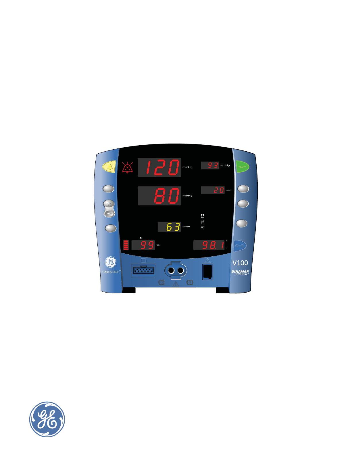
The CARESCAPE V100 vital signs monitor provides a small, portable, easy-to-use
monitoring alternative for sub-acute hospital and non-hospital settings. The
monitor is for use on adult, pediatric, or neonatal patients—one at a time. The
battery-operated monitor offers noninvasive determination of systolic blood
pressure, diastolic blood pressure, mean arterial pressure, pulse rate, oxygen
saturation, and temperature. Monitors are available with or without integrated
printers as well as the following parameters and technologies.
NIBP, Pulse: SuperSTAT, Auscultatory, or Classic
SpO
Temperature: Alaris Turbo Temp, Alaris Tri-Site, or Exergen
The model of the CARESCAPE V100 vital signs monitor determines which
parameters are in your monitor. Please refer to applicable sections.
Using the CARESCAPE V100 vital signs monitor, a clinician can measure, display,
and record patient vital sign data that is derived from each parameter. The
monitor is also capable of alerting the clinician to changes in the patient’s
condition or when it is unable to effectively monitor the patient’s condition. The
monitor also detects alarm limit conditions and gives audible and visual
notification of these conditions. All of the main operations of the monitor are
easy-to-use and only a button-touch away. Please review the factory default
settings and, where applicable, enter settings appropriate for your use.
: Ohmeda TruSignal, Nellcor OxiMax, or Masimo SET
2
Indications for use
The CARESCAPE V100 vital signs monitor is for use as prescribed by physicians,
physician assistants, registered nurses, certified registered nurse anesthetists, or
other qualified medical personnel trained in the use of the equipment. The
CARESCAPE V100 vital signs monitor is intended to monitor and measure
oscillometric noninvasive blood pressure (systolic, diastolic, and mean blood
pressure), heart rate/pulse, oxygen saturation (SpO
oximetry, and temperature using fast predictive mode or continuous monitor
mode. An interface to the Exergen TAT-5000 temporal scanner is also provided.
Using this monitor, a clinician can view, record, and recall clinical data derived
from each parameter.
CARESCAPE V100 vital signs monitors are intended for use in various markets,
from the physician’s office to sub-acute triage and medical/surgical units. The
CARESCAPE V100 vital signs monitor is intended to monitor one patient at a time
in a clinical setting.
) by noninvasive pulse
2
1-2 CARESCAPE V100 Vital Signs Monitor 2048723-001A
Page 15

Introduction: Safety message signal words
Safety message signal words
Safety message signal words designate the severity of a potential hazard.
Danger: Indicates a hazardous situation that, if not avoided, will result in death
or serious injury.
Warning: Indicates a hazardous situation that, if not avoided, could result in
death or serious injury.
Caution: Indicates a hazardous situation that, if not avoided, could result in
minor or moderate injury.
Contraindications
This device is not designed, sold, or intended for use except as indicated.
WARNINGS
To avoid personal injury, do not perform any servicing unless
qualified to do so.
If powering the monitor from an external power adapter or
converter, use only GE-approved power adapters and
converters.
Carefully route the external AC/DC power converter, air hoses,
and all cables to reduce the possibility of entanglement or
strangulation.
Do not immerse monitor in water. If monitor is splashed with
water or becomes wet, wipe it immediately with a dry cloth.
Do not immerse sensors in water, solvents, or cleaning
solutions (the sensors and connectors are not waterproof).
Examine the power cord periodically. Discontinue use and
replace if damaged. Replace the power cord, as necessary,
with a regulatory-approved cord for the country of use.
Avoid swinging the monitor, or entangling the monitor and its
accessories with a mount or roll-stand, as this could cause the
monitor to drop, leading to patient or user injury, and
equipment damage.
If any of the seven-segment indicator lights fails to illuminate
during the display test, the accuracy of vital sign values could
be misread. This indicates problems with the display. Contact
GE Technical Support.
Do not perform any testing or maintenance on a sensor while it
is being used to monitor a patient.
2048723-001A CARESCAPE V100 Vital Signs Monitor 1-3
Page 16

Introduction: Contraindications
WARNINGS
Verify calibration of NIBP parameter (temperature and pulse
oximeter do not require calibration; refer to the service manual
for instructions).
The monitor should only be used by people who have
familiarized themselves with its operation.
Keep the monitor and its accessories out of the patient’s reach
when not in use.
Place the monitor on a rigid, secure surface or use the monitor
with mounting hardware, poles, and stands recommended by
GE.
Only use the monitor in areas where adequate ventilation
exists.
Do not use any battery other than a GE recommended battery.
Other batteries may not provide the same operating time and
may cause unexpected monitor shut-down. Other batteries
may be incompatible with the internal charger and may cause
battery acid leakage, fire, or explosion.
Caution should be taken to not set alarm limits to extreme
values, as this can render the alarm system useless.
CAUTIONS
Federal law (U.S.A.) restricts this device to sale by or on the
order of a physician.
The performance of the monitor may be degraded if it is
operated or stored outside of the environmental conditions
specified in this manual.
The monitor meets standards IEC 60601-1 and ISO 9919 for
shock and vibration. If the monitor is subjected to conditions
exceeding these standards, performance may be degraded.
Do not use the monitor in the presence of magnetic resonance
imaging (MRI) devices. There have been reports of sensors
causing patient burns when operating in an MRI environment.
Do not use the monitor in the presence of flammable
anesthetics.
Do not use in the presence of an oxygen-enriched atmosphere
(oxygen tent).
1-4 CARESCAPE V100 Vital Signs Monitor 2048723-001A
Page 17

Introduction: Contraindications
CAUTIONS
Operating the monitor near equipment which radiates highenergy electromagnetic and radio frequencies (electrosurgical/
cauterizing equipment, portable radios, cellular telephones,
etc.) may cause false alarm conditions. If this happens,
reposition the monitor and temperature probe away from the
source of interference and perform a new measurement.
Do not gas sterilize or autoclave the monitor.
The monitor should not be used on patients who are connected
to cardiopulmonary bypass machines.
The monitor does not include any user-replaceable fuses. Refer
servicing to qualified service personnel.
To reduce the risk of electric shock, do not remove the cover or
the back. Refer servicing to a qualified service person.
If the accuracy of any determination reading is questionable,
first check the patient’s vital signs by alternate means and
then check the monitor for proper functioning.
To help prevent unintended current return paths with the use of
high frequency (HF) surgical equipment , ensure that the HF
surgical neutral electrode is properly connected.
Do not exceed a load weighing 5 lb. (2.7 kg) in the accessory
basket.
To prevent cross-contamination, clean exterior surfaces of the
monitor, monitor accessories, and reusable sensors on a
regular basis in compliance with your institution's infection
control unit and/or biomedical department's local policy.
Do not disassemble the monitor as personal injury may result.
NOTES
This equipment is suitable for use in the presence of electrosurgery.
The use of approved accessories will provide protection from burns during
high frequency surgery.
2048723-001A CARESCAPE V100 Vital Signs Monitor 1-5
Page 18

Introduction: Product compliance
Product compliance
CARESCAPE V100 vital signs monitor
Compliance classifications
The monitor is classified in the following categories for compliance with IEC
60601-1:
Internally powered or Class II when powered from external supply.
Transportable.
For continuous operation.
Not suitable for use in the presence of flammable anesthetics.
Not for use in the presence of an oxygen-enriched atmosphere (oxygen
tent).
Type BF defibrillator-proof applied parts.
IPX1, degree of protection against ingress of water.
Sterilization/Disinfection, refer to Appendix C, “Maintenance” .
Software is developed in accordance with IEC 60601-1-4.
The monitor complies to IEC 60601-2-49.
The alarm system is developed in accordance with IEC 60601-1-8.
This equipment is suitable for connection to public mains via power.
adapters as defined in CISPR 11.
The SpO
The NIBP parameter complies to IEC 60601-2-30, EN 1060-1, EN 1060-3, and
ANSI/AAMI SP10.
The Temperature parameter complies to ASTM E-1112-00.
Defibrillation protected. When used with the recommended accessories, the
monitor is protected against the effects of defibrillator discharge. If
monitoring is disrupted by the defibrillation, the monitor will recover.
This product conforms with the essential requirements of the Medical
Device Directive 93/42/EEC. Accessories without the CE mark are not
guaranteed to meet the Essential Requirements of the Medical Device
Directive.
parameter complies to ISO 9919.
2
1-6 CARESCAPE V100 Vital Signs Monitor 2048723-001A
Page 19

Introduction: Product compliance
Electromagnetic compatibility (EMC)
WARNINGS
Use of known RF sources, such as cell/portable phones, or
other radio frequency (RF) emitting equipment near the system
may cause unexpected or adverse operation of this device/
system. Consult qualified personnel regarding device/system
configuration.
Use only approved accessories, including mounts and
defibrillator-proof cables. For a list of approved accessories,
see the supplies and accessories list delivered with the manual.
Other cables and accessories may cause a safety hazard,
damage the equipment or system, result in increased
emissions or decreased immunity of the equipment or system
or interfere with the measurement.
CAUTIONS
The equipment or system should not be used adjacent to, or
stacked with, other equipment . If adjacent or stacked use is
necessary, the equipment or system should be tested to verify
normal operation in the configuration in which it is being used.
EMC — Magnetic and electrical fields are capable of interfering
with the proper performance of the device. For this reason
make sure that all external devices operated in the vicinity of
the monitor comply with the relevant EMC requirements. X-ray
equipment or MRI devices are a possible source of interference
as they may emit higher levels of electromagnetic radiation.
Changes or modifications to this device/system not expressly
approved by GE Healthcare may cause EMC issues with this or
other equipment . This device/system is designed and tested to
comply with applicable standards and regulations regarding
EMC and needs to be installed and put into service according
to the EMC information stated as follows: This device/system is
suitable for use in all establishments other than domestic and
those directly connected to the public low-voltage power
supply network that supplies buildings used for domestic
purposes. Mains power should be that of a typical commercial
or hospital environment.
NOTE
Medical electrical equipment require special electromagnetic compatibility
(EMC) precautions which must be considered when installing and putting
this equipment into operation. Refer to the service manual for information.
2048723-001A CARESCAPE V100 Vital Signs Monitor 1-7
Page 20
Introduction: Symbols
Exergen temporal scanner
The Exergen temporal scanner has these additional classifications:
Type BF applied part
Internally powered (battery operated)
IPX0, degree of protection against ingress of water
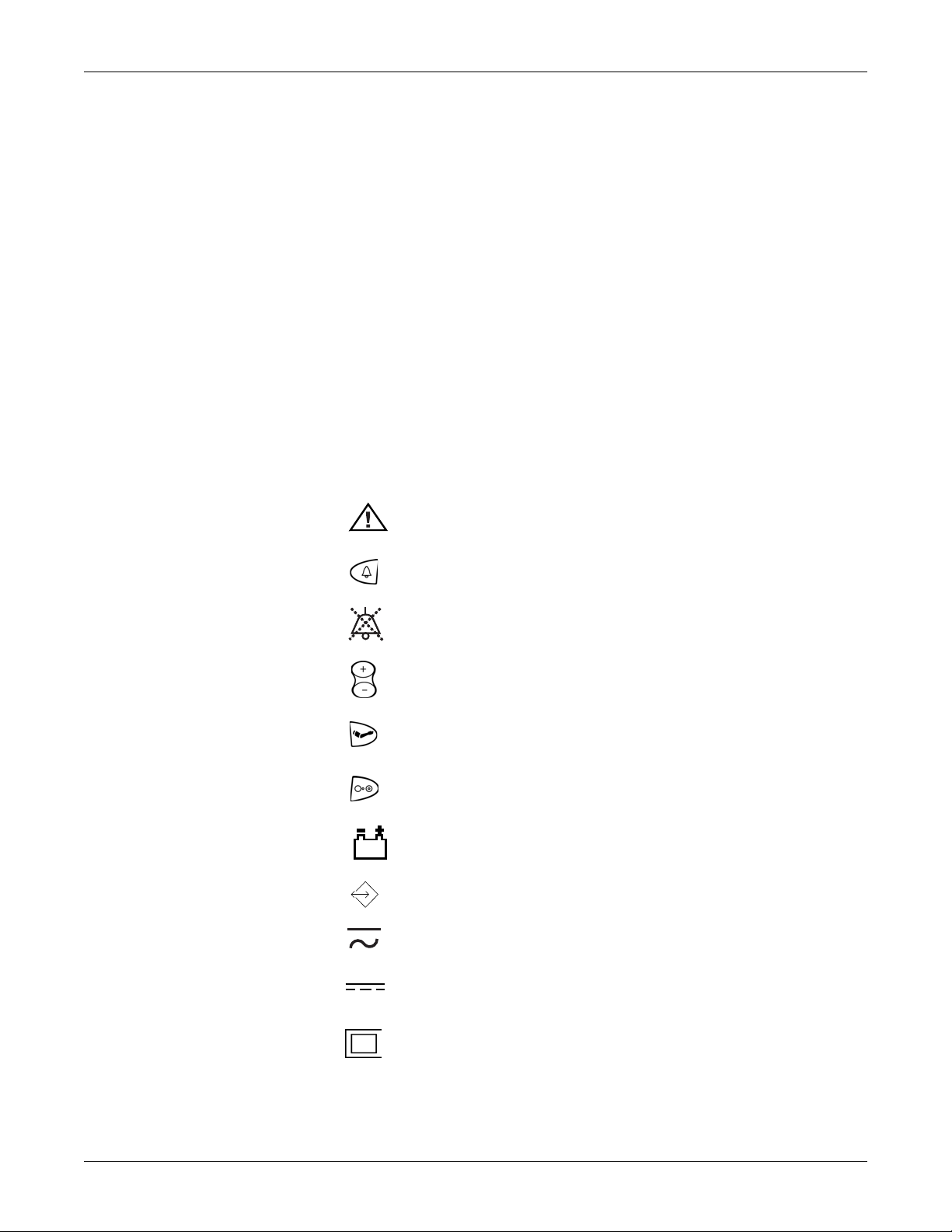
Symbols
The following symbols are associated with the monitor and Exergen temporal
scanner.
CARESCAPE V100 vital signs monitor
NOTE
The model of the monitor determines which symbols appear on it .
Attention, consult accompanying documents
Silence
Alarms Silence
+ / - Increase / decrease adjustable settings
Inflate/Stop
On/Off
Battery Power
External communications port connector
Charging
External DC power input
Class II equipment
1-8 CARESCAPE V100 Vital Signs Monitor 2048723-001A
Page 21
Introduction: Symbols
2006-12
IPX1
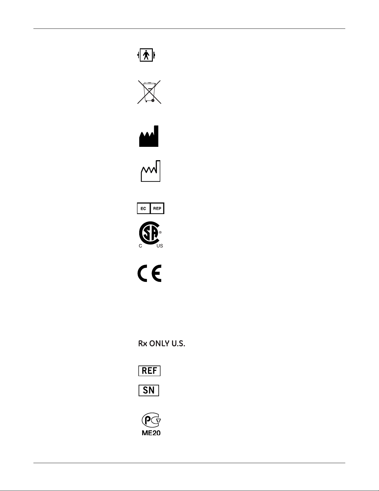
Defibrillator-proof type BF equipment
WASTE OF ELECTRICAL AND ELECTRONIC EQUIPMENT (WEEE): This
symbol indicates that the waste of electrical and electronic
equipment must not be disposed as unsorted municipal waste and
must be collected separately. Please contact an authorized
representative of the manufacturer for information concerning the
decommissioning of your equipment.
Manufacturer: This symbol is accompanied by the name and the
address of the manufacturer.
Manufacturing Date: This symbol is accompanied by the date of the
manufacturing.
European authorized representative.
Classified with respect to electric shock, fire, and mechanical and
other specified hazards only in accordance with CAN/CSA C22.2 No.
601.1 and UL 2601-1 (UL 60601-1). Also evaluated to
IEC 60601-2-30.
This product conforms with the essential requirements of the
Medical Device Directive 93/42/EEC. Accessories without the CE
mark are not guaranteed to meet the Essential Requirements of the
Medical Device Directive.
This product is protected against vertically falling drops of water
and conforms with the IEC 60529 Standard at level of IPX1. No
harmful effects will come of vertically falling drops of water making
contact with the monitor.
FDA Prescriptive Device symbol for: “Caution: Federal law
restricts this device to sale by or on the order of a
physician.”.
Catalog or orderable part number.
Device serial number.
Russia only. GOST-R mark.
2048723-001A CARESCAPE V100 Vital Signs Monitor 1-9
Page 22
Introduction: Symbols
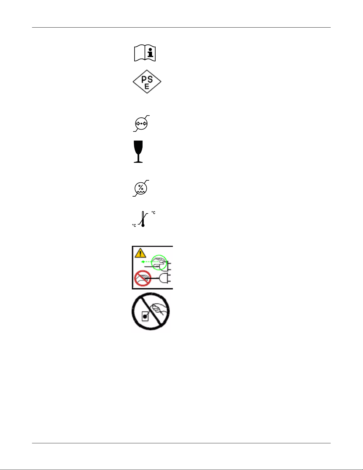
Consult instructions for use.
The PSE mark (Product Safety Electric Appliance and Materials) is
a mandatory mark required on Electrical Appliances in Japan as
authorized by the Electrical Appliance and Material Safety Law
(DENAN).This mark signifies that a product complies with the law
according to a set of standards for electric devices.
Atmospheric pressure limitations.
Fragile. Handle with care.
Humidity limitations.
Temperature limitations.
CAUTION
— Safety ground precaution. Remove power cord
from the mains source by grasping the plug. Do not pull on
the cable.
1-10 CARESCAPE V100 Vital Signs Monitor 2048723-001A
Page 23
Exergen temporal scanner
2006-12
IPX0
Introduction: About this manual
Attention, consult accompanying documents.
Type BF Applied Part.
WASTE OF ELECTRICAL AND ELECTRONIC EQUIPMENT (WEEE): This
symbol indicates that the waste of electrical and electronic
equipment must not be disposed as unsorted municipal waste and
must be collected separately. Please contact an authorized
representative of the manufacturer for information concerning the
decommissioning of your equipment.
Manufacturer: This symbol is accompanied by the name and the
address of the manufacturer.
Manufacturing Date: This symbol is accompanied by the date of the
manufacturing.
About this manual
Printed copies of this manual
A paper copy of this manual will be provided upon request. Contact your local GE
representative and request the part number on the first page of the manual.
Ordinary Equipment.
“On” (only for part of Equipment)
2048723-001A CARESCAPE V100 Vital Signs Monitor 1-11
Page 24

Introduction: About this manual
Conventions used in this manual
Within this manual, special styles and formats are used to distinguish between
terms viewed on screen, a button you must press, or a list of menu commands
you must select:
For technical documentation purposes, the abbreviation GE is used for the
legal entity name, GE Medical Systems Information Technologies, Inc.
In this manual, the CARESCAPE V100 vital signs monitor is referred to as the
monitor.
Names of hardware keys on the equipment , keypad, remote control, and
modules are written in bold typeface: Go/Stop.
Menu items are written in bold italic typeface: Monitor Setup.
Emphasized text is in italic typeface.
Menu options or control settings selected consecutively are separated by
the > symbol: Procedures > Cardiac Output.
When referring to different sections in this manual, section names are
enclosed in double quotes: “Cleaning and care.”
The word “select” means choosing and confirming.
Messages (alarm messages, informative messages) displayed on the screen
are written inside single quotes: 'Learning.'
Note statements provide application tips or other useful information.
Any illustrations appearing in this manual are provided as examples only.
They may not necessarily reflect your monitoring setup or data displayed on
your monitor.
Any names appearing in examples and illustrations are fictitious. The use of
any real person’s name is purely coincidental.
Revision history
Revision Comments
A Initial release of this document.
1-12 CARESCAPE V100 Vital Signs Monitor 2048723-001A
Page 25

2 Getting started
2048723-001A CARESCAPE V100 Vital Signs Monitor 2-1
Page 26

Getting started: Unpacking the monitor and accessories
Unpacking the monitor and accessories
Before attempting to use the monitor, take a few minutes to become acquainted
with the monitor and its accessories. Unpack the items carefully. This is also a
good time to check for any damage or accessory shortage. If there is a problem
or shortage, contact GE.
It is recommended that all the packaging be retained, in case the monitor must
be returned for service in the future.
Setting up NIBP connections
1. Connect the end of the air hose that
has quick-release clips to the NIBP
connector on the front of the monitor.
Make sure that the hose is not kinked or
compressed.
NOTE
To disconnect the hose from the
monitor, squeeze the quick-release
clips together and pull the plug
from the NIBP connector.
2. Select appropriate cuff size. Measure patient’s limb and select appropriately
sized cuff according to size marked on cuff or cuff packaging. When cuff
sizes overlap for a specified circumference, choose the larger size cuff.
WARNING
Accuracy of NIBP measurement depends on using a cuff of the
proper size. It is essential to measure the circumference of the
limb and to select the proper size cuff. In addition, the air hoses
are color-coded according to patient population. The gray 12or 24-foot hose (3.66 m or 7.3 m) is required on patients who
require cuff sizes from infant through thigh cuffs. The light blue
12-foot hose (3.66 m) is required for the neonatal cuff sizes #1
through #5. If it becomes necessary to move the cuff to
another limb, make sure the appropriate size cuff is used.
3. Inspect cuff for damage. Replace cuff when aging, tearing, or weak closure
is apparent. Do not inflate cuff when unwrapped.
CAUTION
Do not use cuff if structural integrity is suspect.
2-2 CARESCAPE V100 Vital Signs Monitor 2048723-001A
Page 27

Getting started: Setting up SpO2 connections
4. Connect the cuff to the air hose. Refer to “Chapter 7, “NIBP” ” of this manual
for complete cuff connection instructions.
CAUTION
Always use the appropriate hose and cuff combination for the
patient. Any attempt to modify the hose may inhibit the
monitor from switching between the neonate and adult/
pediatric measurement modes.
NOTE
Care should be taken in reconnecting the cuff to a hose, ensuring that
threads of the cuff and hose are in alignment and no cross-threading
occurs.
5. Refer to Chapter 7, “NIBP” of this manual for complete instructions on taking
an accurate NIBP determination.
NOTES
Use only GE CRITIKON BP cuffs. The size, shape, and bladder
characteristics can affect the performance of the instrument.
Inaccurate readings may occur unless GE CRITIKON Blood Pressure
cuffs are used. Refer toAppendix B, “Accessories” for reorder codes.
The ADULT indicator encompasses both adult and pediatric patients.
Setting up SpO2 connections
1. Plug the appropriate SpO2 sensor into the SpO2 sensor extension cable.
2. Then plug the SpO
on the monitor.
3. Refer to the applicable “SpO2” section of this manual for complete
instructions on monitoring SpO
sensor extension cable into the SpO2 sensor connector
2
.
2
2048723-001A CARESCAPE V100 Vital Signs Monitor 2-3
Page 28
Getting started: Setting up temperature connections
1
2
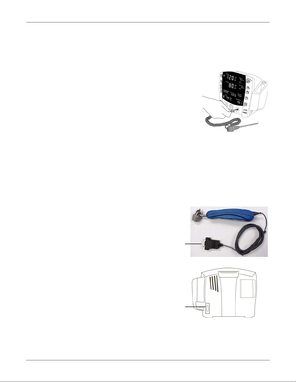
Setting up temperature connections
Alaris
1. Connect the temperature probe cable to
the temperature probe connector on the
monitor.
2. Insert the temperature probe into the
probe holster at the side of the monitor.
3. Refer to Chapter 11, “Alaris Temperature
– Turbo Temp and Tri-Site” section of this
manual for complete instructions on
taking a temperature reading.
Exergen
NOTE
Specific error messages that display on the scanner’s LED window will not
display on the monitor. Instead, error conditions will be indicated on the
monitor by ‘E--’.
NOTE
No more than one Exergen scanner should be connected and used with the
monitor at a time.
1. Connect the scanner’s
modular plug (1) to the Host
Communication port (2) at
the back of the monitor.
2. Secure the plug using the
two thumbscrews on the
plug.
3. Refer to Chapter 12,
“Exergen Temperature”
section of this manual for
complete instructions on
taking a temperature
reading.
2-4 CARESCAPE V100 Vital Signs Monitor 2048723-001A
Page 29
Getting started: Setting up the printer (installing the paper)
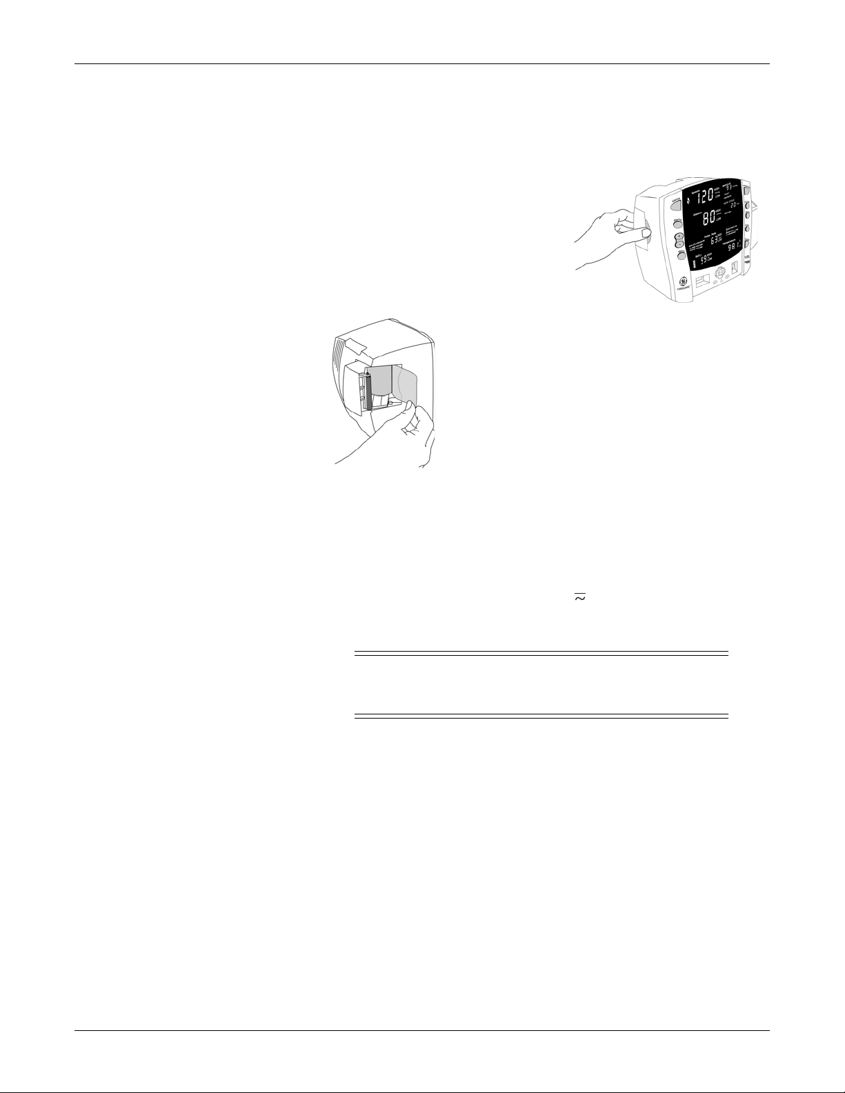
Setting up the printer (installing the paper)
1. With the monitor powered on, turn it so
that the side with the printer is facing
you.
2. While grasping the side of the monitor,
lift the printer door open by placing your
thumb in the indented area and pulling.
The printer door will pop open.
3.Place the roll of paper into the compartment so that
the end of the paper comes off the right-side of the roll
(paper is wound around the roll clockwise). Place the
roll of paper in the holding bracket that is integrated in
the door of the printer, making sure the paper extends
out of the printer cavity at least two inches.
4.Firmly press the door to close it.
Power sources
The monitor is designed to operate either from an external power source (mains)
or from an internal battery. Refer to “Specifications” on page 3-13 for details.
With external DC power connected, the green CHARGING indicator will light
to indicate that the battery is charging.
DANGER
ELECTRIC SHOCK — Do not touch the patient and the DC power
input connector pins simultaneously.
2048723-001A CARESCAPE V100 Vital Signs Monitor 2-5
Page 30

Getting started: Turning the monitor on and off
WARNING
Examine the power cord periodically. Discontinue use and
replace if damaged. Replace the power cord, as necessary,
with a regulatory-approved cord for the country of use.
NOTES
Be sure to unplug the power supply from the AC outlet before transport.
Even if connected to an external power source, the monitor is not
designed to operate without an internal battery.
Using the power cord supplied with the monitor, connect it to the power line. Use
only the original cord, a power cord recommended by GE, or a regulatoryapproved cord for the country of use.
Turning the monitor on and off
To turn the monitor on, push the power On/Off button. As the monitor powers
up, it runs a short self-test (display test) in which all seven-segment indicator
lights illuminate. When the monitor is powered on, it generates a start-up sound.
This start-up sound consists of 5 separate tones generated in succession.
WARNINGS
Inspect the device for damage before use.
If any of the seven-segment indicator lights fails to illuminate
during the display test, the accuracy of vital sign values could
be misread. This indicates problems with the display. Contact
GE Technical Support.
If the monitor fails to sound the start-up tones, do not use the
monitor. This indicates problems with the audible alarm circuit.
Contact GE Technical Support.
To turn the monitor off, push the power On/Off button again. This will terminate
any measurements that may be in progress and automatically deflate the cuff.
2-6 CARESCAPE V100 Vital Signs Monitor 2048723-001A
Page 31

Automatic shutdown
When in clinical mode
Getting started: Procedure for testing alarms
The monitor has an automatic shutdown feature in order to conserve battery
life.
In clinical mode, the monitor automatically shuts down after an inactive period
of 15 minutes.
NOTE
Refer to “Clinical mode” on page 3-7 for a description of clinical mode.
Certain conditions or actions that can delay or disable auto shutdown are:
The monitor is operating on external DC power.
The SpO
The NIBP mode of operation is auto or Stat mode.
An NIBP determination is in progress.
Any alarm other than BATTERY LOW or ‘E13’ BATTERY LOW is active.
Any remote command/request is received via the host communications
protocol.
A temperature determination is in progress.
A button is pressed.
The monitor is in configuration or advanced configuration mode.
parameter is monitoring vitals.
2
In configuration and advanced configuration
delay auto shutdown. The monitor automatically shuts down after an inactive
period of 15 minutes even if powered by external DC power.
Procedure for testing alarms
1. With the monitor on and the NIBP hose not connected to the front of the
monitor, press the Inflate/Stop button.
2. Verify that after approximately 15 seconds the alarm sounds and the
monitor generates an ‘E83’ alarm.
3. To clear the alarm, press the Silence button.
Configuration mode settings
Monitor settings such as HIGH/LOW alarm settings changed in the clinical mode
will not be retained after the monitor is powered off. To retain alarm and
parameter settings, the changes must be done in the configuration mode. Date/
Time settings are also entered in the Configuration mode.
modes, pressing any button will
2048723-001A CARESCAPE V100 Vital Signs Monitor 2-7
Page 32

Getting started: Configuration mode settings
Entering configuration mode
With the monitor off, press and hold the Menu button at the same time as
pressing the On/Off button until the display test completes.
NOTE
displays in the Systolic window. As the monitor turns on in the
configuration mode, a brief display appears showing the software
revision, NIBP technology, and temperature technology of the monitor.
These displays appear only during the first part of the power up
sequence and are not selectable and cannot be changed.
Display Window
Major software revision Systolic
Minor software revision Diastolic
Type of NIBP technology min
Type of temperature technology Temperature
The type of NIBP technology selected in the monitor is displayed in the min
(minutes display) window as follows:
AUSC if the monitor is configured with auscultatory NIBP Algorithm
STAT if the monitor is configured with DINAMAP SuperSTAT Algorithm
CLAS if the monitor is configured with DINAMAP Classic Algorithm
The type of temperature probe selected in the monitor is displayed in the
Temperature window as follows:
trb0 if the monitor is configured for Alaris Turbo Temp
trI if the monitor is configured for Alaris Tri-Site
tat if the monitor is configured for Exergen
The Menu selections appear in the following order. Refer to each manual section
for settings options.
Menu selections for SpO
differ depending upon the technology. Refer to Chapter
2
8, “Ohmeda TruSignal SpO2” , Chapter 9, “Nellcor OxiMax SpO2” and Chapter 10,
“Masimo SET SpO2” sections for options.
Setting Setting LED window LED display
Inflate pressure (adult/ped) Systolic XXX (numeric)
Inflate pressure (neonate) Systolic XXX (numeric)
Line frequency mode
SpO2
(Ohmeda TruSignal only)
SpO
mode
2
SpO2
(Nellcor & Masimo only)
2-8 CARESCAPE V100 Vital Signs Monitor 2048723-001A
Page 33

Getting started: Configuration mode settings
Setting Setting LED window LED display
SpO
sat
2
(Nellcor & Masimo only)
SpO2
SpO
sensitivity
2
SpO2
(Masimo only)
Temperature units
(Alaris Turbo Temp or Tri-Site
Degrees °C or °F will
be illuminated
only)
Temperature display time Temperature
Year Systolic
Month MAP/Cuff
Day Diastolic
Hour min
Minute min
Mode
Systolic
(when main screen is active)
2048723-001A CARESCAPE V100 Vital Signs Monitor 2-9
Page 34

Getting started: Configuration mode settings
Configuring the default vital sign alarm limits
WARNINGS
Monitors located in the same clinical area but containing
different alarm default settings can result in a potential hazard.
Always check your alarm settings before using the monitor.
Caution should be taken to not set alarm limits to extreme
values, as this can render the alarm system useless.
To set the default vital sign alarm limits, complete the following procedure:
1. With the monitor off, press and hold the Menu button at the same time as
pressing the On/Off button until the display test completes.
2. Press the Alarms button until the limit value you want to change is
displayed in the applicable vital sign window. The HIGH, LOW, ADULT, and
NEONATE screen labels identify what limit value default you are setting.
3. Use the +/- buttons to increase or decrease the selected value.
4. To exit the configuration mode, turn the unit off. To continue with additional
configuration settings, press the Menu button.
Reverting to the factory default vital sign alarm limits
WARNING
The Line Frequency mode (for Datex-Ohmeda oximetry) must
be set according to each country’s electrical power utilities
implementation; and that it must be checked and reset any
time the monitor is set to or reverts to factory default settings.
To revert to the factory default vital sign alarm limit settings, the monitor must
be disconnected from the DC power supply and from the monitor battery. Refer
to “Replacing the battery” on page C-8 for DC power supply and battery
disconnection/reconnection instructions,
When reverting to factory default settings, the user settings (including alarm
limits and inflation pressure), date/time, and the Ohmeda TruSignal SpO
Frequency mode (LF) will go back to default values. Refer to “Configuration mode
settings” on page 2-7 to configure the factory default user settings.
NOTE
For monitors configured for Ohmeda TruSignal SpO
setting for Line Frequency mode (LF) is correct for your country. Refer to
“Configuration settings associated with SpO2” on page 8-5.
Line
2
2 only, verify that the
2-10 CARESCAPE V100 Vital Signs Monitor 2048723-001A
Page 35

Getting started: Configuration mode settings
Setting the date and time
To set the date and time on the monitor, you must access the configuration
mode. Press Menu to skip the default settings that do not require changes. Refer
to the above table.
NOTE
Procedures
1. Press the Menu button to move from one setting to another. Use the +/-
2. To exit the configuration mode, press the On/Off button.
3. To continue with other changes, press the Menu button. appears in the
While in configuration mode, all entries stored in the clinical history are
erased when the time and/or date is changed.
buttons to increment or decrement the setting.
NOTE
For the date and time to be saved, you must advance the menu through
the minute setting.
Systolic window. To change parameter settings, press the Menu button and
select the parameter function. To change alarm settings, press the Alarms
button.
2048723-001A CARESCAPE V100 Vital Signs Monitor 2-11
Page 36

Getting started: Configuration mode settings
SpO2 configuration settings
Procedure for units with Ohmeda TruSignal technology
NOTE
Refer to Chapter 8, “Ohmeda TruSignal SpO2” for options.
1. With the monitor off, press and hold the Menu button at the same time as
pressing the On/Off button until the display test completes.
2. Press the Menu button until LF appears in the Pulse Rate window.
3. Use the +/- buttons to select the option.
4. To exit the configuration mode, turn the unit off. To continue with additional
configuration settings, press the Menu button.
Procedure for units With Nellcor technology
NOTE
Refer to Chapter 9, “Nellcor OxiMax SpO2” for options.
1. With the monitor off, press and hold the Menu button at the same time as
pressing the On/Off button until the display test completes.
2. Press the Menu button until n0d (response mode) appears in the Pulse Rate
window.
3. Use the +/- buttons to select the option.
4. Press the Menu button once. SAt (SatSeconds) appears in the Pulse Rate
window.
5. Use the +/- buttons to select the option.
6. To exit the configuration mode, turn the unit off. To continue with additional
configuration settings, press the Menu button.
Procedure for units with Masimo technology
NOTE
Refer to Chapter 10, “Masimo SET SpO2” for options.
1. With the monitor off, press and hold the Menu button at the same time as
pressing the On/Off button until the display test completes.
2. Press the Menu button until n0d (averaging time) appears in the Pulse Rate
window.
3. Use the +/- buttons to select the option.
4. Press the Menu button once. SAt (FastSAT) appears in the Pulse Rate
window.
5. Use the +/- buttons to select the option.
6. Press the Menu button once. SEn (sensitivity mode) appears in the Pulse
Rate window.
2-12 CARESCAPE V100 Vital Signs Monitor 2048723-001A
Page 37

Getting started: Configuration mode settings
1
3
2
1
7. Use the +/- buttons to select the option.
8. To exit the configuration mode, turn the unit off. To continue with additional
configuration settings, press the Menu button.
Temperature hardware configuration settings
Changing the Alaris temperature unit of measurement
(Refer to Chapter 11, “Alaris Temperature – Turbo Temp and Tri-Site” for options.)
1. With the monitor off, press and hold the Menu button at the same time as
pressing the On/Off button until the display test completes.
2. Press the Menu button until Unt (unit of measurement) appears in the Pulse
Rate window.
3. Use the +/- buttons to select the option.
4. To exit the configuration mode, turn the unit off. To continue with additional
configuration settings, press the Menu button.
Changing the Exergen temperature unit of measurement
The Exergen scanner comes preset with the requested unit of temperature
measurement, but can be changed. To change the scanner’s unit of
measurement (°C or °F):
1. Disconnect the scanner cable from the monitor.
Loosen the two screws from the scanner’s modular plug.
Unplug the scanner cable from the monitor’s Host Communication
port.
2. Loosen the single screw (1) from the bottom, on the back of the scanner, and
remove the battery cover (2).
2048723-001A CARESCAPE V100 Vital Signs Monitor 2-13
3. Disconnect and remove the battery (3).
Page 38

Getting started: Configuration mode settings
1
°F
°C
4. To set the unit of measurement to:
°F — move the F/C switch (1) up toward the probe cone.
°C — move the F/C switch (1) away from the probe cone.
5. Replace the battery and cover, then tighten the screw.
6. Reconnect the scanner cable to the Host Communication port and tighten
the two screws.
Changing temperature display time
(Refer to Chapter 11, “Alaris Temperature – Turbo Temp and Tri-Site” or Chapter
12, “Exergen Temperature” for options.)
1. With the monitor off, press and hold the Menu button at the same time as
pressing the On/Off button until the display test completes.
2. Press the Menu button until tdt (temperature display time) appears in the
Pulse Rate window.
3. Use the +/- buttons to select the option.
4. To exit the configuration mode, turn the unit off. To continue with additional
configuration settings, press the Menu button.
2-14 CARESCAPE V100 Vital Signs Monitor 2048723-001A
Page 39

Getting started: Advanced configuration mode
Advanced configuration mode
Advanced configuration is used for viewing and printing the failure alarm
history. In addition, qualified service personnel use advanced configuration for
configuring the monitor’s serial port communication settings,
Entering advanced configuration mode
With the monitor off, press the On/Off button at the same time as pressing
and holding the Menu and - (minus) buttons.
NOTE
ACF displays in the Systolic window. As the monitor turns on in the
advanced configuration mode, a brief display appears showing the
software version of the monitor.
Display Window
Major software revision Systolic
Minor software revision Diastolic
Printing the failure alarm history
NOTE
Refer to chapter Chapter 4, “Printer” for printout details.
1. With the monitor off, press the On/Off button at the same time as pressing
and holding the Menu and - (minus) buttons.
2. Press the Print button once. All failure alarm entries in the failure alarm
history are printed n the order of the most recent to the oldest. Each entry is
printed on one line.
3. To exit the advanced configuration mode, press the On/Off button for less
than 5 seconds.
2048723-001A CARESCAPE V100 Vital Signs Monitor 2-15
Page 40

For your notes
Getting started: Advanced configuration mode
2-16 CARESCAPE V100 Vital Signs Monitor 2048723-001A
Page 41

3 Product overview
2048723-001A CARESCAPE V100 Vital Signs Monitor 3-1
Page 42

Buttons
Product overview: Buttons
1. Silence button: mutes audible alarms. Any other active alarm that can be
acknowledged is also cleared and the alarm condition is reset whenever this
key is pressed. When pressed, the alarm silence indicator (bell) lights solid
red to indicate that audible alarms have been silenced for 2 minutes. Alarm
silence can be cancelled by pressing the Silence button again.
2. Alarms button: used to view or adjust parameter alarm limit settings.
3. +/- buttons (Plus/Minus): used when you are in the following modes: limit,
menu, cycle, and history.
When you are in limit or menu setting, pressing the +/- button increases
and decreases an adjustable setting.
When you are in cycle or history mode, pressing the +/- buttons
displays the next or previous cycle selection or entry in the history list,
respectively.
When you reach the beginning or ending of a list, a negative key-click
sounds.
4. Menu button: accesses menu settings that can be adjusted: INFLATE
PRESSURE (ADULT and NEONATE), ALARM VOLUME, and PULSE VOLUME.
NOTE
Refer to “Clinical mode” on page 3-7 for a description of clinical mode.
NOTE
(Refer to“Operating (system) modes” on page 3-7 for a description of
operating mode.)
NOTE
ADULT indicator encompasses both adult and pediatric patients.
5. SpO
6. NIBP connector: attach NIBP cuff hoses here.
3-2 CARESCAPE V100 Vital Signs Monitor 2048723-001A
sensor connector: attach SpO2 cables here.
2
Page 43

Product overview: Front panel
HISTORY
AUTO CYCLE
MAP/Cuff
BATTERY
Pul se Rat e
Temperature
SpO
C
F
Diastolic
Syst o l i c
ALARM VOLUME
HIGH
HIGH
HIGH
HIGH
LOW
LOW
LOW
LOW
CHARGIN G
PULSE VOLUM E
IN FLA TE PRESSURE
16
17
18
21
22
23
15
24
25
26
28
28
29
20
19
ADULT
NEONATE
30
31
OK
27
29
30
31
32
33
7. Inflate/Stop button: starts a manual NIBP determination or stop any NIBP
determination.
8. Temperature probe holster: stores Alaris temperature probe.
9. Cycle button: used to select NIBP mode of manual, auto cycle, or Stat mode.
10. Temperature probe cover storage: stores Alaris probe covers.
11. History button: activates the history mode to view stored patient data. The
most recent entries are displayed first. Press and hold the button for 2
seconds to clear all entries stored; the adaptive inflate pressure setting
returns to the configured setting. Refer to Chapter 6, “History” for more
information.
12. Print button: prints currently displayed values or all stored entries when in
history mode.
13. On/Off button: controls on/off state of monitor; push for power on and push
again for power off.
14. Alaris temperature probe connector: attach temperature probe cable here.
(The Exergen scanner connects to the Host Communications port at the
back of the system. Refer to the “Rear panel” on page 3-5.
Front panel
15. Alarm silence indicator:
Solid red: Indicates that an alarm silence is active and the audible alarm
tones are silenced for 2 minutes.
Blinking red (Legacy alarm mode only): Indicates that an alarm silence is
not active and at least one alarm condition is present .
16. Systolic window: indicates measured systolic NIBP in mmHg.
17. Diastolic window: indicates measured diastolic NIBP in mmHg.
2048723-001A CARESCAPE V100 Vital Signs Monitor 3-3
Page 44

Product overview: Front panel
18. INFLATE PRESSURE indicator: flashes to indicate you are making a change
to the inflation pressure. Adjustable for adult/ped and neonate patients.
19. ALARM VOLUME indicator: flashes to indicate you are making a change to
the alarm volume.
20. PULSE VOLUME indicator: flashes to indicate you are making a change to
the pulse volume.
21. Pulse Rate window: shows pulse rate in beats per minute.
22. SpO
23. SpO2
pulse indicator: flashing red LED bar indicates that pulses are being
2
derived from SpO
window: indicates oxygen saturation in %.
signals.
2
24. MAP/Cuff window: indicates measured mean arterial pressure (MAP) in
mmHg and shows cuff pressure during NIBP determination.
25. ADULT indicator: lights to indicate you are making a change to adult/ped
NIBP limits or inflation pressure settings.
26. NEONATE indicator: lights to indicate you are making a change to neonate
NIBP limits or inflation pressure settings.
27. AUTO CYCLE indicator: lights green to indicate auto mode is the chosen
NIBP mode; flashes to indicate you are making a change to the auto mode.
28. Min window: displays the NIBP mode if manual or Stat as well as the cycle
time when taking auto NIBP determinations.
29. HISTORY indicator: flashes to indicate you are in history mode.
30. BATTERY OK indicator: lights green to indicate the monitor is operating on
battery power and that the battery is sufficiently charged.
31. BATTERY LOW indicator: lights amber to indicate low charge for the battery
(less than 45 minutes when solid; 5 min or less when flashing).
32. CHARGING indicator: lights green to indicate presence of external power
source and battery charging.
33. Temperature window: indicates measured temperature.
3-4 CARESCAPE V100 Vital Signs Monitor 2048723-001A
Page 45

Rear panel
Product overview: Rear panel
35
34
34. Host communications port (15 pin D-type RS-232 serial port) for use only
with equipment conforming to IEC 60601-1 or configured to comply with IEC
60601-1-1. The Exergen scanner connects to this port.
NOTES
Refer to Appendix A, “Connections” for connection details.
Attach one accessory to this port.
35. Printer door.
2048723-001A CARESCAPE V100 Vital Signs Monitor 3-5
Page 46

Right-side panel
Product overview: Right-side panel
36
Windows
Indicators
36. External DC power socket: used with GE-approved AC-DC power converter
only. Refer to Appendix B, “Accessories” for the part number of the
approved power supply.
Each derived vital sign has an associated window for displaying the value. For
each window, the vital sign’s name and unit of measure are labeled above and
to the right of it, respectively. An additional window--the min window--is
available for displaying the NIBP mode or chosen AUTO CYCLE selection.
Indicators are text messages and icons that are positioned on the front of the
monitor. Each indicator can be backlit one color, either red, green or amber.
Indicators are described in the appropriate sections throughout this manual.
3-6 CARESCAPE V100 Vital Signs Monitor 2048723-001A
Page 47

Product overview: Operating (system) modes
Operating (system) modes
The monitor can operate in one of six modes:
Clinical
Configuration
Advanced configuration
Service
Battery low shutdown
System failure
Clinical mode
Clinical mode is the mode used to monitor patients.
How to enter and exit clinical mode
To enter clinical mode:
With the monitor off, press the On/Off button.
To exit clinical mode:
With the monitor on, press the On/Off button for less than 5 seconds.
While in clinical mode:
All parameters are available for monitoring.
Alarm limits and all user settings are adjustable.
Configuration mode
Configuration mode is used for configuring or customizing how the monitor
operates in clinical mode. Configuration mode briefly displays the software
revision in the Systolic and Diastolic windows, the configured NIBP technology
in the min window, and the configured temperature technology in the Pulse
Rate window.
How to enter and exit configuration mode
To enter configuration mode:
With the monitor off, press the On/Off button at the same time as pressing
and holding the Menu button.
To exit configuration mode:
With the monitor on, press the On/Off button for less than 5 seconds.
2048723-001A CARESCAPE V100 Vital Signs Monitor 3-7
Page 48

Product overview: Operating (system) modes
While in configuration mode:
All parameters are inoperable.
The Systolic window displays indicating the monitor is in configuration
mode.
Applicable default settings are configurable to their user-preferred default
settings.
Advanced configuration mode
Advanced configuration is used for configuring the monitor’s serial port
communication settings as well as viewing and printing the failure alarm history.
Advanced configuration mode displays the software revision in the Systolic and
Diastolic windows.
How to enter and exit advanced configuration mode
To enter advanced configuration mode:
With the monitor off, press the On/Off button at the same time as pressing
and holding the Menu and - (minus) buttons.
To exit advanced configuration mode:
With the monitor on, press the On/Off button for less than 5 seconds.
While in advanced configuration mode:
All parameters are inoperable.
The Systolic window displays ACF indicating the monitor is in Advanced
configuration mode.
A failure alarm history can be viewed and printed.
NOTE
Refer to the service manual for instructions for use concerning advanced
configuration mode.
Service mode
Service mode is used to configure and calibrate various components of the
monitor's hardware.
NOTE
The service mode is intended for use by qualified service personnel only. For
instructions concerning service mode, refer to the service manual.
Battery low shutdown
Battery low shutdown is entered when the high-priority BATTERY LOW alarm
has been active for 5 minutes. Refer to Chapter 5, “Alarms” for details and error
codes. Refer to the service manual for detailed battery instructions.
3-8 CARESCAPE V100 Vital Signs Monitor 2048723-001A
Page 49

System failure
User modes
Menu mode
Product overview: User modes
System failure mode is entered when the monitor has a depleted battery, or a
hardware or software failure. A distinctive alarm tone is generated for up to 5
minutes, after which if the monitor isn’t turned off, it shuts down completely.
Refer to Chapter 5, “Alarms” for details and error codes. Refer to the service
manual for detailed instructions.
The monitor has four user modes that are available during clinical operating
mode: menu, cycle, limit adjustment, and history.
The menu mode allows you to access and change the three settings associated
with the following indicators: INFLATE PRESSURE (ADULT and NEONATE), ALARM
VOLUME, and PULSE VOLUME.
Inflate pressure
To enter this mode, press the Menu button. Each press of the Menu button steps
you through each of the these settings.
After 7 seconds of not pressing the Menu button, the menu mode is
automatically exited. Otherwise, you can exit the menu mode by cycling through
all menu options. Upon exiting menu mode, the main monitoring screen is
displayed. Alarm and pulse volume settings are retained after power-off.
INFLATE PRESSURE (ADULT, NEONATE) is reset to its configured default after
power-off.
Procedure
NOTE
This setting is available for two patient types: adult and neonate. The adult
setting is applicable to both adult and pediatric determinations.
1. Press the Menu button. The INFLATE PRESSURE indicator flashes, and—at
the same time—the ADULT indicator and the value in the Systolic window
light showing you that the INFLATE PRESSURE for ADULT setting is ready to
be changed.
2. To change the associated value, simply use the +/- button to increment or
decrement, respectively.
3. Press the Menu button again. The INFLATE PRESSURE indicator flashes,
and—at the same time—the NEONATE indicator and the value in the
Systolic window light showing you that the INFLATE PRESSURE for
NEONATE setting is ready to be changed.
4. To change the associated value, simply use the +/- button to increment or
decrement, respectively.
2048723-001A CARESCAPE V100 Vital Signs Monitor 3-9
Page 50

Alarm volume
Pulse volume
Cycle mode
Product overview: User modes
Procedure
1. Press the Menu button. The ALARM VOLUME indicator flashes.
2. To change the associated value, simply use the +/- button to increment or
decrement, respectively.
Procedure
1. Press the Menu button. The PULSE VOLUME indicator flashes.
2. To change the associated value, simply use the +/- button to increment or
decrement, respectively.
The cycle mode allows you to start auto cycle and Stat modes.
Limit adjustment mode
1. Press the Cycle button. The AUTO CYCLE indicator flashes.
2. To change the time increment while the AUTO CYCLE indicator flashes,
simply use the +/- button to increment or decrement, respectively. When
you reach the beginning or ending of the list, the negative key-click sounds.
OR
3. While the AUTO CYCLE indicator flashes, you can also press the Cycle
button until you reach the desired time increment.
Refer to Chapter 7, “NIBP” for more information.
The limit adjustment mode allows you to change alarm limit settings that are
used while monitoring a patient. To enter this mode, press the Alarms button. All
alarm limit settings return to their default settings after power-off. To change the
associated limit, simply use the +/- button to increment or decrement,
respectively. The range and increment/decrement steps for each derived vital
sign that has adjustable limits are described in each parameter section. The step
size specified (which cannot be adjusted) tells how much the limit value will
change per increment/decrement key press and also dictates how close
together a pair of limits can be.
Limit-adjustable vital signs are displayed in the following order:
ADULT:
Systolic HIGH, LOW
Diastolic HIGH, LOW
3-10 CARESCAPE V100 Vital Signs Monitor 2048723-001A
Page 51

Product overview: Sounds
NEONATE:
Systolic HIGH, LOW
Diastolic HIGH, LOW
Pulse Rate:
HIGH, LOW
History mode
Sounds
SpO
NOTES
The temperature and MAP (mean arterial pressure) vital signs are not
Only NIBP limits (Systolic and Diastolic) are adjustable based on the patient
The history mode allows you to access the stored patient data. When the history
mode is active, pressing the +/- buttons displays the next or previous entry in the
history list. When you reach the beginning or end of the list, a negative key-click
sounds. Pressing the History button also allows you to view the previous entry.
NOTE
:
2
HIGH, LOW
checked against alarm limits.
type.
Refer to Chapter 6, “History” for more information.
Start-up sound
User interaction sounds
Positive key tone
The monitor generates sounds based upon user interaction, parameter events,
and physiological, technical, or system failure alarms.
When the monitor is powered on a start-up sound is generated. This start-up
sound consists of 5 separate tones generated in succession. Refer to “Turning
the monitor on and off” on page 2-6 for more details.
When pressing a button results in its intended function being performed, one
audible tone sounds.
2048723-001A CARESCAPE V100 Vital Signs Monitor 3-11
Page 52

Negative key tone
Alarm sounds
High priority
Low priority
Product overview: Sounds
When pressing a button results in its intended function not being performed,
three audible tones sound.
The monitor generates high priority and low priority alarm sounds, each with a
different sound. These sounds repeat with the rate dependent on the priority of
the alarm and for as long as the alarm is active and not silenced. When alarms
of multiple priorities are active, only the highest-priority alarm sound is audible.
The high-priority alarm sounds three high-pitched tones followed by two highpitched tones.
The low-priority alarm sounds a single low-pitched tone followed by a single
higher-pitched tone.
Battery low shutdown and system failure sounds
When the monitor enters either of these modes, it generates a sound that
remains on until the monitor either automatically shuts down or is turned off.
This sound consists of a high-pitched tone that repeats at a very high rate.
Battery charger sounds
The battery charger sounds are generated—whether the monitor is on or off—
whenever the external DC charger is connected and disconnected.
When connected to the monitor, the battery charger sounds a single lowpitched tone followed by a single higher-pitched tone. Upon disconnection from
the monitor, the battery charger sounds a single high-pitched tone followed by a
single lower-pitched tone.
3-12 CARESCAPE V100 Vital Signs Monitor 2048723-001A
Page 53

Product overview: Power sources
Power sources
The monitor is designed to operate from an internal lead-acid battery. For
replacement rechargeable batteries, please refer to “Replacing the battery” in
Appendix C, “Maintenance” of this manual.
Specifications
Specifications
Mechanical
Dimensions
Height 7.7 in (19.5 cm)
Width 8.6 in (21.9 cm) without Alaris temperature
10.0 in (25.4 cm) with Alaris temperature
Depth 5.3 in (13.5 cm)
Weight (Including battery) 5.4 lb (2.4 kg)
Mountings Self-supporting on rubber feet, pole mounted, or wall mount bracket
Portability Carried by recessed handle
Power requirements
Power converter universal P/N: 2018859-001
Protection against electrical shock Class II
AC input 100 to 240VAC, 0.5A
DC output voltage 12VDC at 1A
The AC mains power adapter contains a nonresettable and
nonreplaceable fuse.
Monitor
Protection against electrical shock Internally powered or Class II when powered from specified external
power supply.
DC input voltage 12 VDC, supplied from a source conforming to IEC 60601-1.
Fuses The monitor contains three fuses. The fuses are mounted within the
monitor. The fuses protect the low voltage DC input, the main battery,
and the remote alarm output. The +5 V output on the host port connector
is regulated by internal supply.
Main Battery Refer to Chapter 14, “Battery”
Environmental
Operating temperature + 5°C to + 40°C
(+ 41°F to + 104°F)
2048723-001A CARESCAPE V100 Vital Signs Monitor 3-13
Page 54

Product overview: Specifications
Specifications
Operating atmospheric pressure 500 hPa to 1060 hPa
Storage/transportation
Storage temperature – 20°C to + 50°C
(– 4°F to + 122°F)
Atmospheric pressure 500 hPa to 1060 hPa
Humidity range 5% to 95% noncondensing
Radio frequency Complies with IEC Publication 60601-1-2 Medical Electrical Equipment,
Electromagnetic Compatibility Requirements and Tests and CISPR 11
(Group 1, Class B) for radiated and conducted emissions
3-14 CARESCAPE V100 Vital Signs Monitor 2048723-001A
Page 55

4 Printer
2048723-001A CARESCAPE V100 Vital Signs Monitor 4-1
Page 56

Description
2
3
4
5
6
1
7
Printer: Description
The printer is an optional feature to the monitor. If your monitor contains a
printer, each time a printout is started the following information is printed.
Installing the paper
Print button
Item Name
1
Monitor name and model number
Current software revision. The software revision letters map to a numeric
2
software revision. (e.g., RAE is the equivalent of R1.5. Where A=1, B=2...Z=26).
Area for patient name and hand-written comments
3
Unit of measure
4
Vital signs data, if available
5
Date and time
6
Column and parameter labels
7
Refer to “Setting up the printer (installing the paper)” on page 2-5 for instructions.
You can print in both clinical and advanced configuration modes. In clinical
mode, you can print both currently displayed values and history. In advanced
configuration mode you can print a failure alarm history. Refer to the service
manual for more information on the use of the Print button while in advanced
configuration mode.
4-2 CARESCAPE V100 Vital Signs Monitor 2048723-001A
Page 57

Printer: Printouts
In clinical mode, pressing the Print button prints everything on the screen. Since
measurements may have been taken at different times, a time stamp is printed
with each parameter. Values are printed in order of the most recent (newest) to
the oldest.
By pressing the Print button when in history mode, all entries currently stored in
the history are printed in order of the most recent to the oldest.
To tear off the printout, use a slight sideways action to pull the paper sharply up
across the edge of the door.
NOTE
If the Print button was pressed during the first 10 seconds of SpO
monitoring, dashes will appear for SpO
and pulse rate readings.
2
2
The availability of the printer is determined at the time the printout is started.
When the printer is unavailable, the Print button makes a negative key sound
when you press it. The printer is unavailable when:
The printer is out of paper, too hot, or if the monitor is in any of the following
modes: cycle, alarm limit adjustment, menu, configuration, or service.
The battery is nearly depleted. In this case, a high-priority ‘E13’ BATTERY
LOW alarm sounds and the BATTERY LOW indicator flashes. No printouts of
any type will print.
Printouts
Current (real time)
For this printout, the following information may be printed:
SpO
info line:
2
The time the Print button was pressed.
The displayed SpO
and pulse rate values are printed under the SpO2
2
and pulse rate columns along with the time stamp.
If values are not displayed, ‘---’ is printed.
PIr info line:
The time the Print button was pressed—only if the monitor is configured
for Ohmeda TruSignal SpO
The perfusion index measurement is printed when it is valid. Dashes are
2.
printed when it is invalid (the sensor is not applied to the patient).
NIBP info line:
The displayed NIBP values and the time that these values were
completed.
The displayed pulse rate values if they were completed at the same
time as the displayed NIBP values.
2048723-001A CARESCAPE V100 Vital Signs Monitor 4-3
Page 58

Clinical history
Failure alarm history
Printer: Paper storage
Temperature info line:
The values of a previous temperature measurement if they are still
displayed in the Temperature window.
The time that the measurement completed.
The above lines are printed in the order of most recent to oldest with the
exception of the PIr info line, which always follows the SpO
info line. If the
2
date changes between entries, a single line containing the date is printed.
All entries currently stored in the clinical history list when the Print button is
pressed are printed in the order of the most recent (newest) to the oldest. For a
value that was violating its high limit when it was stored, an up arrow is printed
after the value. For a value that was violating its low limit when it was stored, a
down arrow is printed after that value. If the date changes between entries, a
single line containing the date is printed.
Paper storage
The monitor must be in advanced configuration mode to print the failure alarm
history. Press the History button to enter the history mode. Then, when the Print
button is pressed, all entries in the failure alarm history are printed. They are
printed in the order of the most recent to the oldest. Each entry is printed on one
line and that line contains, from left to right, the following:
Time of day as HH:MM, in military time, the failure was detected
Date the failure was detected as DD-Month-YYYY, where DD is the day,
Month is the month spelled out and YYYY is the year
System error code for the detected failure
Store thermal paper in a cool, dry place. The printed strip (thermal paper
recording) should not be
Exposed to direct sunlight
Exposed to temperatures over 38°C/100°F or relative humidity over 80%
Placed in contact with adhesives, adhesive tapes, or plasticizers such as
those found in all PVC page protectors
NOTES
When in doubt about long-term storage conditions, store a photocopy of
the thermal paper recording.
The paper is thermally activated; therefore, do not store it in a hot place as
discoloration may result.
Use only replacement paper rolls (P/N 089100 for box of 10) from GE.
4-4 CARESCAPE V100 Vital Signs Monitor 2048723-001A
Page 59

Printer: Alarms
Alarms
Refer to Chapter 5, “Alarms” for detailed information regarding printer alarms.
Specifications
Specifications
Printer type Thermal dot array
Resolution 384 dots/inch horizontal
Paper type The paper roll used by the printer must be compatible with GE PN
770137.
Languages printed English, German, French, Italian, Spanish, Portuguese, Hungarian, Polish,
Czech, Finnish, Swedish, Danish, Dutch, Norwegian, and Slovak
Languages not printed
(text printed in English only)
Russian, Greek, Korean, Japanese, Turkish and Lithuanian
2048723-001A CARESCAPE V100 Vital Signs Monitor 4-5
Page 60

For your notes
Printer: Specifications
4-6 CARESCAPE V100 Vital Signs Monitor 2048723-001A
Page 61

5 Alarms
2048723-001A CARESCAPE V100 Vital Signs Monitor 5-1
Page 62

Description
During an alarm condition, the monitor may generate an audible alarm signal,
visual alarm signal, alarm message code, and electronic record in the history.
Alarm conditions
Physiological alarm conditions
Physiological alarm conditions are triggered by a patient‘s vital sign exceeding
the parameter limits. Refer to “Alarms and priorities” on page 5-9 for a listing of
related alarm messages and alarm priorities.
The monitor checks each derived vital sign (except MAP and temperature)
against user-set limits. A high-limit alarm is generated when that value is greater
than its high limit. A low-limit alarm is generated when that value is less than its
low limit.
Alarms: Description
Parameter Range Factory default*
Systolic high
(adult)
Systolic low
(adult)
Diastolic high (adult) 15 to 220 120
Diastolic low
(adult)
Systolic high
(neonate)
Systolic low
(neonate)
Diastolic high
(neonate)
Diastolic low
(neonate)
Pulse rate high
(adult and neonate)
Pulse rate low
(adult and neonate)
SpO
high
2
(adult and neonate)
low
SpO
2
(adult and neonate)
*To change alarm default settings, refer to Chapter 2, “Getting started” .
35 to 290 200
30 to 285 80
10 to 215 30
35 to 140 100
30 to 135 40
15 to 110 60
10 to 105 20
35 to 235 150
30 to 230 50
71 to 100 100
70 to 99 90
5-2 CARESCAPE V100 Vital Signs Monitor 2048723-001A
Page 63

Technical alarm conditions
Technical alarm conditions are triggered by an electrical, mechanical, or other
failure of the equipment, or by a sensor or component failure. Technical alarm
conditions may also be caused when an algorithm cannot classify or interpret
the available data.
Refer to “Alarms and priorities” on page 5-9 for a listing of related alarm
messages and alarm priorities.
Battery alarm conditions
Refer to Chapter 14, “Battery” for detailed information regarding battery alarms.
Printer alarm conditions
When any of the printer alarm conditions occur, the alarm code flashes in the
min window. When a printer alarm condition is active, you can acknowledge
and clear the alarm by pressing the Silence button. If an ‘E13’ BATTERY LOW
alarm is active, it takes precedence over active printer alarms and ‘E13’ appears
in the min window.
Alarms: Alarm conditions
Memory alarm conditions
The ‘E00’ memory lost alarm is generated on power-up when battery backed
RAM has been corrupted. When it occurs, all settings are reset to their factory
defaults and all entries in clinical history are erased.
When detected while powering-up in clinical, configuration, or advanced
configuration mode, the status code related to this condition flashes in the
Systolic window and the appropriate alarm sound becomes audible. While the
‘E00’ memory lost alarm is active, all parameters remain in their offline state and
only the Silence button is available.
NOTE
If an ‘E00’ memory alarm occurs, all settings revert to the factory default. The
clinician should check the monitor configuration settings to verify that they are
set as desired. For monitors configured for Ohmeda TruSignal SpO
that the setting for line frequency mode (LF) is correct for your country. Refer to
“Configuration settings associated with SpO2” on page 8-5
only, verify
2
2048723-001A CARESCAPE V100 Vital Signs Monitor 5-3
Page 64

Alarms: Alarm modes
System failure alarm conditions
The system failure mode is activated when there is a hardware or software
failure. To view and print a system failure entry, the monitor must be in
advanced configuration mode.
During a system failure alarm condition, the following occurs:
The Systolic window displays a failure error code.
The failure sound is generated for up to 5 minutes.
To turn the monitor off, press the On/Off button for less than 5 seconds.
After alarming for up to 5 minutes the monitor shuts down completely.
NOTES
Refer to “Alarms and priorities” on page 5-9 for a listing of related alarm
messages and alarm priorities.
Refer to the service manual for instructions concerning system failure mode.
Alarm modes
IEC alarm mode
Legacy alarm mode
The monitor may be configured to operate in one of two different alarm modes:
IEC or Legacy. The IEC mode is 60601-1-8 compliant. The Legacy mode matches
the alarm signal behavior used by previous versions of this monitor. The factory
configuration is IEC. Refer to the “CARESCAPE V100 Vital Signs Service Manual” to
configure the alarm mode setting.
In IEC alarm mode, the monitor’s alarm silence indicator has two states:
Solid red: alarm silence is active.
Off: alarm silence is not active.
In Legacy alarm mode, the monitor’s alarm indicator has three states:
Solid red: alarm silence is active.
Blinking red: alarm silence is not active and audible alarm tones sound
when at least one alarm condition is present .
Off: alarm silence is not active and no alarm condition is present.
5-4 CARESCAPE V100 Vital Signs Monitor 2048723-001A
Page 65

Alarm signals
Audible alarm signals
Alarms: Alarm signals
The monitor provides visual and audible alarm signals when an alarm condition
is present. All alarm conditions are accompanied by an audible signal unless an
alarm silence is active.
When multiple alarm conditions occur, the following conditions apply:
If more than one alarm occurs at the same time, the monitor will sound an
alarm tone for the highest priority alarm. Any lower priority audible alarm
tones are suppressed by the higher priority alarm tone.
If more than one alarm of the same priority occurs, the monitor sounds the
appropriate priority audible alarm tone and flashes the associated alarm
message codes.
The monitor produces three different alarm tones depending on the alarm
condition that is present:
High-priority alarm tone repeats a pattern of three high-pitched tones
followed by two high-pitched tones.
Low-priority alarm tone repeats a pattern of two tones.
System failure or battery low shutdown alarm tone is a single, continuous
high-pitched tone.
Visual alarm signals
NOTE
IEC alarm silence indicator
When the monitor is in the IEC alarm mode, the alarm silence indicator has two
states:
Solid red: Alarm silence is active and the audible alarm tones are silenced for
Off: Alarm silence is not active.
Legacy alarm silence indicator
When the monitor is in the Legacy alarm mode, the alarm silence indicator has
three states:
Solid red: Alarm silence is active and the audible alarm tones are silenced for
Blinking red: Alarm silence is not active and at least one alarm condition is
Off: Alarm silence is not active and no alarm condition is present.
Refer to the “CARESCAPE V100 Vital Signs Service Manual” to configure the
IEC or Legacy alarm mode setting.
2 minutes.
2 minutes.
present.
2048723-001A CARESCAPE V100 Vital Signs Monitor 5-5
Page 66

Flashing screen text
Alarms: Silencing an alarm
High priority alarm conditions will flash:
Vital sign values that exceed the alarm limit settings will flash in the
associated monitor window. The associated HIGH or LOW limit indicator will
also flash.
Alarm message codes will flash in the monitor windows when technical-
level problems with a parameter measurement, sensor, or equipment are
present.
Remote alarms
In Legacy alarm mode, low priority SpO
“spot mode” time period is active:
‘---’ alarm code will flash in the SpO
alarm condition is present.
‘E25’ alarm code will flash in the SpO
is present.
If either of these low-priority alarm conditions are not acknowledged within
one minute, they automatically escalate to a high-priority alarm condition.
NOTE
Refer to the “CARESCAPE V100 Vital Signs Service Manual” to configure the
alarm mode setting
A remote alarm activates when any high priority alarm or system failure alarm is
active, or if the monitor is powered off. Low priority alarms do not latch remote
alarms. Remote alarms are an output of the host communication port. Refer to
“Host port connector” on page A-2 for additional information on the host port
connector and the remote alarm signal.
NOTE
When using remote alarms, the
source. The remote alarm is considered a secondary alarm source and should be
used for remote purposes only.
monitor
alarm conditions will flash if the SpO2
2
window when a SpO2 sensor off finger
2
window when a SpO2 lost pulse alarm
2
should be considered the primary alarm
Silencing an alarm
To silence a patient-related alarm (physiological or technical alarms) at anytime,
press the Silence button. The alarm silence indicator (bell) lights solid red to
indicate that audible alarms have been silenced for 2 minutes.
NOTE
The high-pitched, continuous system failure or battery low shutdown
audible alarm tone sounds regardless of an alarm silence being active.
5-6 CARESCAPE V100 Vital Signs Monitor 2048723-001A
Page 67

Alarms: Acknowledging an alarm
Acknowledging an alarm
Some parameter limit and technical alarms are acknowledgeable when the
Silence button is pressed. Acknowledging an alarm clears the audible and visible
alarm signals and resets the alarm condition. For a list of acknowledgeable
alarms, refer to “Alarms and priorities” on page 5-9.
Adjusting vital sign alarm limits
WARNINGS
Monitors located in the same clinical area but containing
different alarm default settings can result in a potential hazard.
Always check your alarm settings before using the monitor.
Caution should be taken to not set alarm limits to extreme
values, as this can render the alarm system useless.
NOTES
The temperature and MAP vital signs are not checked against alarm limits.
Only NIBP limits (diastolic and systolic) are adjustable based on the patient
type.
All changes are temporary and return to the default configuration settings
when the monitor is turned off. To permanently change the alarm settings
refer to “Configuration mode settings” on page 2-7.
To adjust the alarm limit settings, complete the following procedure:
1. Press the Alarms button until the limit value you want to change is
displayed in the applicable vital sign window. The HIGH, LOW, ADULT, and
NEONATE screen labels identify what limit value default you are setting.
2. Press the +/- buttons to increase or decrease the selected value.
3. To exit this function, choose one of the following:
Press the Alarms button until the main monitoring screen appears.
Let the monitor time-out by not touching any of the monitor buttons.
After a few seconds, the main monitoring screen appears.
2048723-001A CARESCAPE V100 Vital Signs Monitor 5-7
Page 68

Alarms: Adjusting the alarm volume
Reverting to the factory default vital sign alarm limits
WARNING
The Line Frequency mode (for Datex-Ohmeda oximetry) must
be set according to each country’s electrical power utilities
implementation; and that it must be checked and reset any
time the monitor is set to or reverts to factory default settings.
To revert to the factory default vital sign alarm limit settings, the monitor must
be disconnected from the DC power supply and from the monitor battery. Refer
to “Replacing the battery” on page C-8 for DC power supply and battery
disconnection/reconnection instructions,
When reverting to factory default settings, the user settings (including alarm
limits and inflation pressure), date/time, and the Ohmeda TruSignal SpO
Frequency mode (LF) will go back to default values. Refer to “Entering
configuration mode” on page 2-8 to configure the factory default user settings.
NOTE
For monitors configured for Ohmeda TruSignal SpO
setting for Line Frequency mode (LF) is correct for your country. Refer to
“Configuration settings associated with SpO2” on page 8-5.
Line
2
2 only, verify that the
Adjusting the alarm volume
NOTE
Adjustment to the alarm volume setting is retained after the monitor is powered
off.
To adjust the volume for all alarm tones on the monitor, complete the following
procedure:
1. Press the Menu button until ALARM VOLUME flashes in green.
The current alarm volume setting is displayed in the Diastolic window.
2. Press the +/- buttons to increase or decrease the selected value.
The selectable alarm volume range is from 1 to 10 (10 being the loudest). The
positive key tone that sounds when you press the +/- buttons relates
directly to the alarm volume setting selected.
3. To exit this function, choose one of the following:
Press the Alarms button until the main monitoring screen appears.
Let the monitor time-out by not touching any of the monitor buttons.
After a few seconds, the main monitoring screen appears.
5-8 CARESCAPE V100 Vital Signs Monitor 2048723-001A
Page 69

Alarms and priorities
In this table, the alarm condition is indicated with the following: physio. =
physiological, technical = technical, and system = system failure.
Alarms: Alarms and priorities
Alarm
message
code
(if any)
NIBP alarms
E89 NIBP no
E85 BP level timeout Remained at one cuff
E84 BP total timeout Length of time has
Alarm detected Cause
NIBP Systolic high Value is greater than the
HIGH alarm limit
NIBP Systolic low Value is less than the LOW
alarm limit
NIBP Diastolic
high
NIBP Diastolic low Value is less than the LOW
determination
Value is greater than the
HIGH alarm limit
alarm limit
NIBP failed. Reapply cuff technical yes high
pressure level for more than
1 minute.
exceeded 2 minutes for an
adult/pediatric
determination or 85
seconds for a neonate
determination.
Alarm
condition
physio. yes high
physio. yes high
physio. yes high
physio. yes high
technical yes high
technical yes high
Acknowledgeable
by pressing
Silence?
1
Alarm
priority
E83 NIBP pump
timeout
E82 NIBP excess air in
cuff
E80 NIBP
overpressure
2048723-001A CARESCAPE V100 Vital Signs Monitor 5-9
Pressure leak. Check or
replace hose or cuff
Determination cannot be
made due to an excess
amount of air in the cuff.
Excess cuff pressure. Check
for hose blockage
technical yes high
technical yes high
technical yes high
Page 70

Alarms: Alarms and priorities
Alarm
message
code
(if any)
SpO
alarms
2
E20 SpO
E21 SpO
--- SpO
Alarm detected Cause
high Value is greater than the
SpO
2
HIGH alarm limit
low Value is less than the LOW
SpO
2
alarm limit
sensor
2
Sensor disconnected technical yes high
disconnected
2
sensor
2
replace
sensor off
Sensor broken or wrong
type. Replace
Sensor off finger technical yes IEC: high
finger
Alarm
condition
Acknowledgeable
by pressing
Silence?
1
Alarm
priority
physio. no high
physio. no high
technical yes high
Legacy: low,
escalating to
high in “spotmode.”
Otherwise,
3,4
high.
E25 SpO2 lost pulse Lost pulse technical yes IEC: high
Temperature alarms
E61 Temp probe
Probe broken. Replace technical no high
broken (Alaris
only)
E63 Temp probe
disconnected
Disconnected or wrong
probe
technical yes high
(Alaris only)
E66 Temp probe too
Probe too hot technical yes high
hot (Alaris only)
E-- Temp scanner
error
(Exergen only)
Exergen battery low, or
invalid temperature value.
Also, check the scanner’s
technical yes high
display. Refer to Chapter 12,
“Exergen Temperature” for
more information.
Legacy: low,
escalating to
high in “spotmode.”
Otherwise,
3, 4
high.
5-10 CARESCAPE V100 Vital Signs Monitor 2048723-001A
Page 71

Alarms: Alarms and priorities
Alarm
message
code
(if any)
Alarm detected Cause
Alarm
condition
Acknowledgeable
by pressing
Silence?
1
Pulse rate alarms
Pulse rate high Value is greater than the
HIGH alarm limit
Pulse rate low Value is less than the LOW
alarm limit
physio. no-SpO
yes-NIBP
physio. no-SpO
yes-NIBP
,
2
,
2
Printer alarms
E10 Printer no paper Printer no paper technical yes high
E11 Printer too hot Printer too hot technical yes high
Battery alarms
E13 Battery low Battery too low technical yes
Battery low Battery is running low and
technical
yes
2
should be plugged in
Alarm
priority
high
high
high
low,
escalating to
high when
approx. 5
minutes of
battery
charge
remains.
E00 Memory lost Memory loss
Usually noted after
changing batteries.
User settings and date/
time revert to default
settings.
For units with Ohmeda
TruSignal technology,
verify the Line Frequency
(LF) mode setting. Refer to
“Configuration settings
associated with SpO2” on
page 8-5.
technical yes high
2048723-001A CARESCAPE V100 Vital Signs Monitor 5-11
Page 72

Alarms: Specifications
Alarm
message
code
(if any)
Alarm detected Cause
Alarm
condition
Acknowledgeable
by pressing
Silence?
1
Alarm
priority
System failure alarms
900-999 System failure Internal system failure. Refer
system no to the service manual or call
Technical Support for
definitions and instructions
1
Acknowledging an alarm by pressing the Silence button, clears and resets the audible and visible alarm signals and resets the alarm condition.
2
A BATTERY LOW alarm will re-alarm every 10 minutes after it’s been acknowledged.
3
Legacy alarm mode only: The ‘---’ sensor off finger and “E25’ lost pulse alarms are generated as low priority alarms when the SpO2 sensor is on a
patient less than 2 minutes. This is referred to as “spot mode.” If a manual NIBP measurement is taken while “spot mode” is active, the time to
generate a low priority alarm is increased until the NIBP measurement is completed. If the low priority SpO
minute, these low-priority alarms will escalate to high-priority alarms.
4
Legacy alarm mode only: The ‘---’ sensor off finger and “E25’ lost pulse alarms are generated as high priority alarms when “spot mode” is not
active.
alarms are not acknowledged within 1
2
Specifications
Specifications
Alarm volume 60 dB to 75 dB
Remote alarm The remote alarm signals an alarm in 0.5 seconds of the monitor’s
display of the alarm.
Factory default
The factory default for alarm volume is 5.
5-12 CARESCAPE V100 Vital Signs Monitor 2048723-001A
Page 73

6 History
2048723-001A CARESCAPE V100 Vital Signs Monitor 6-1
Page 74

Description
History: Description
NOTE
Age in this section refers to when and how long ago the vital signs were
taken.
The history mode allows you to access stored patient data in clinical mode and a
failure alarm history in advanced configuration mode. The history mode is
especially useful when doing hospital rounds: if the patient’s temperature and
SpO
measurements are taken while an NIBP determination is in progress, then
2
upon completion of the determination, pressing the History button once shows
all vital signs on the same screen for that patient.
The following information refers to operation in clinical mode. The monitor can
hold up to 40 stored entries in history. It displays the most recent entries first.
When full, the oldest entry is removed so the most recent entry can be stored.
Additionally, entries are
hours.
The age of each entry is maintained and displayed in the min window with a
minus sign (-) in front of it when other data stored for that entry is displayed. For
entries that are greater than 59 minutes old, the age is displayed as HH:MM
(hour:min). For entries that are less than or equal to 59 minutes old, the age is
displayed in total minutes.
automatically removed when they become older than 24
When viewing entries in history that are out of limits, the corresponding HIGH or
LOW indicator appears in red.
An entry is stored in history at the completion of an NIBP determination and at
the completion of a successful predictive temperature measurement. At the end
of an NIBP determination, systolic, diastolic, MAP, pulse rate, SpO
temperature (if measurement is completed while the NIBP determination was in
progress) values are stored. However, when continuously monitoring SpO
values are not stored periodically but only when an NIBP determination
completes. At the end of a temperature determination that completes while an
NIBP determination is not in progress, only the temperature value is stored.
, and
2
,
2
To obtain a full set of vitals stored in the same history
entry:
1. Place the SpO2 sensor on patient’s finger and place the cuff on the other
limb.
2. Start the NIBP determination.
3. Take the temperature measurement while the NIBP determination is in
progress.
4. Upon completion of the NIBP determination, remove the cuff and sensor.
5. Press the History button to view all vitals.
6-2 CARESCAPE V100 Vital Signs Monitor 2048723-001A
Page 75

History: Buttons associated with history
Buttons associated with history
Erasing stored history
To activate the history mode, press the
flashes green while this mode is active. With each press of the
patient data stored with the next oldest entry is displayed. Entries are displayed
from the most recent to the oldest. For example, the most recent entry could have
an age of -0 minutes and the oldest entry could have an age of -23:59.
You can also activate the history mode by pushing the History button and then
using the +/- buttons to scroll through the stored entries. Pressing the History
button again exits history mode. Upon exiting history mode, the main monitoring
screen is displayed.
After 15 seconds of not pressing the History or the +/- button, the history mode
is automatically exited. Otherwise, you can exit the history mode by pressing the
History button one more time after viewing the oldest entry. Upon exiting history
mode, the main monitoring screen is displayed.
To erase stored patient data when a static printout in not in progress, press and
hold the History button for a minimum of 2 seconds. All entries that were stored
in history as well as any patient data displayed on the monitor that relates to the
previous determination or the previous temperature measurement are erased.
Pressing and holding the History button for 2 seconds also causes the target
pressure to return to the current value in the INFLATE PRESSURE setting.
History
button. The
HISTORY
History
indicator
button, the
Windows associated with history
Each window on the monitor can be active during history mode. When the
History button is pressed the patient data stored for each entry is displayed in
the applicable windows. Patient data is displayed from most recent to oldest,
indicated by the age in the min window.
Indicators associated with history
The HISTORY indicator is used to show the state of the history mode. When
history mode is active, the HISTORY indicator flashes green.
2048723-001A CARESCAPE V100 Vital Signs Monitor 6-3
Page 76

For your notes
History: Indicators associated with history
6-4 CARESCAPE V100 Vital Signs Monitor 2048723-001A
Page 77

7 NIBP
2048723-001A CARESCAPE V100 Vital Signs Monitor 7-1
Page 78

Description
NIBP: Description
NOTE
Age in this section refers to how long ago the vital signs were taken.
The NIBP parameter in the monitor is available with two types of NIBP
technologies: one calibrated to intra-arterial pressure (DINAMAP SuperSTAT or
Classic) and one calibrated to the auscultatory method (specific technologies are
available in select markets).
The type of NIBP technology used by the monitor is indicated while the monitor
is in the configuration mode. Refer to “Checking the monitor’s NIBP technology
configuration setting” on page 7-11.
Refer to Appendix D, “Principles of Noninvasive Blood Pressure Determination”
for specific information regarding these technologies. Most user interface
options, instructions for use, and alarms will be the same for all technologies.
The NIBP parameter is included in all models. Blood pressure is monitored
noninvasively in the monitor by oscillometric method.
NOTE
For neonatal populations, the reference is always the intra-arterial pressure
monitoring method.
The monitor has three NIBP modes:
mode is selected by the user. The actual NIBP determination is automated and,
once it is complete, the values for systolic pressure, diastolic pressure, mean
arterial pressure, and pulse rate (if SpO
respective windows.
Before each NIBP determination, the monitor performs a test to ensure that the
cuff pressure is below a specified level. The determination is delayed until this
condition is met. The monitor senses the type of hose being used and
automatically uses adult/pediatric monitoring parameters or neonate
monitoring parameters, as appropriate.
Audible and visible alarms occur when any of the values for systolic pressure,
diastolic pressure, or pulse rate (if sourced by NIBP) are outside their selected
high or low limits.
NOTE
When the BATTERY LOW alarm is active as a high-priority alarm, any
attempts to start an NIBP determination results in an ‘E13’ BATTERY LOW
alarm. At anytime during monitoring, if an NIBP determination is started and
cannot be completed due to a low or bad battery, the monitor issues an
‘E13’ BATTERY LOW alarm. Because this particular event can be indicative of
a bad battery, this alarm event is logged into the failure alarm history.
Instructions for cleaning and disinfecting NIBP cuffs are in Appendix C
“Maintenance.”
1. manual, 2. auto cycle, and 3. Stat. The
is not active) are shown in their
2
7-2 CARESCAPE V100 Vital Signs Monitor 2048723-001A
Page 79

NIBP: Description
What is the difference between intra-arterial and auscultatory methods?
Oscillometric method
The oscillometric method of determining NIBP is accomplished by a sensitive
transducer which measures cuff pressure and pressure oscillations within the
cuff. These signals are analyzed by the algorithm that uses one of the references
(intra-arterial or auscultatory) to display the NIBP values.
Intra-arterial reference
The intra-arterial reference algorithm was developed based on blood pressure
values obtained with an intra-arterial catheter (e.g. central aortic).
Auscultatory reference
The auscultatory reference algorithm was developed based on blood pressure
values obtained with a sphygmomanometer, a stethoscope, and listening to the
Korotkoff sounds.
NOTE
NIBP values in the monitor are based on the oscillometric method of
noninvasive blood pressure measurement taken with a cuff on the arm of
adults/pediatrics (SuperSTAT and Classic technologies), a cuff on the calf of
neonates (SuperSTAT technology), and a cuff on the arm of neonates (Classic
technology). The values correspond to comparisons with intra-arterial
values within ANSI/AAMI SP10 Standards for accuracy (a mean difference of
± 5 mmHg, and a standard deviation of <
8 mmHg).
NOTE
Arrhythmias will increase the time required by the NIBP parameter to
determine a blood pressure.
DANGER
Connect cuffs and inflation systems only to systems designed
for non-invasive blood pressure monitoring. Devices with luers
and locking luer connectors may be inadvertently connected to
intravascular fluid systems that may allow air to be pumped
into a blood vessel.
WARNINGS
The monitor will not measure blood pressure effectively on
patients who are experiencing seizures or tremors.
Arrhythmias will increase the time required by the NIBP
parameter to determine a blood pressure and may extend the
time beyond the maximum allowed time for the parameter
(120 seconds for adult/pediatric and 85 seconds for neonate).
2048723-001A CARESCAPE V100 Vital Signs Monitor 7-3
Page 80

NIBP: Description
WARNING
It is possible to set the alarm limits for pulse rate outside of the
operating range for the NIBP parameter. Under such
conditions, an alarm will not occur.
In Manual mode, the monitor displays the results of the last
blood pressure determination for 30 minutes or until another
determination is completed. If a patient's condition changes
between one determination and the next, the monitor will not
detect the change or indicate an alarm condition.
Carefully route the external AC/DC power converter, air hoses,
and all cables to reduce the possibility of entanglement or
strangulation.
Do not place the cuff on a limb being used for intravenous
infusion or any area where circulation is compromised or has
the potential to be compromised.
The monitor is designed for use only with GE CRITIKON BP dualtube cuffs.
Use only GE CRITIKON Blood Pressure Cuffs. The size, shape,
and bladder characteristics can affect the performance of the
instrument . Inaccurate readings may occur unless GE
CRITIKON Blood Pressure Cuffs are used.
A patient’s vital signs may vary dramatically during the use of
cardiovascular agents such as those that raise or lower blood
pressure or those that increase or decrease heart rate.
The monitor will continue to operate until the battery is
completely depleted in order to obtain the full use of the
battery. However, if the battery reaches its 'empty' point during
a BP determination, it will simply stop in the middle of the
determination.
Accuracy of NIBP measurement depends on using a cuff of the
proper size. It is essential to measure the circumference of the
limb and to select the proper size cuff. In addition, the air hoses
are color-coded according to patient population. The gray 12or 24-foot hose (3.66 m or 7.3 m) is required on patients who
require cuff sizes from infant through thigh cuffs. The light blue
12-foot hose (3.66 m) is required for the neonatal cuff sizes #1
through #5. If it becomes necessary to move the cuff to
another limb, make sure the appropriate size cuff is used.
7-4 CARESCAPE V100 Vital Signs Monitor 2048723-001A
Page 81

NIBP: Description
CAUTIONS
Do not use an infant cuff with an auscultatory reference. The
neonatal #5 cuff and neonatal hose may be used on patients
with an arm circumference of 8 - 15 cm.
Blood pressure cuffs should be removed from the patient when
the monitor is powered off. If the extremity remains cuffed
under these conditions or if the interval between blood
pressure determinations is prolonged, the patient’s limb should
be observed frequently and the cuff placement site should be
rotated as needed.
The pulse rate derived from an NIBP determination may differ
from the heart rate derived from an ECG waveform because
the monitor measures actual peripheral pulses, not electrical
signals or contractions from the heart. Differences may occur
because electrical signals at the heart occasionally fail to
produce a peripheral pulse or the patient may have poor
peripheral perfusion. Also, if a patient’s beat-to-beat pulse
amplitude varies significantly (e.g., because of pulsus
alternans, atrial fibrillation, or the use of a rapid-cycling
artificial ventilator), blood pressure and pulse rate readings can
be erratic, and an alternate measuring method should be used
for confirmation.
Several conditions may cause the NIBP parameter to calculate
and display only the mean arterial pressure (MAP) without
systolic and diastolic readings. These conditions include very
low systolic and amplitude fluctuations, so an accurate
calculation for these values can’t be made (e.g., patient in
shock); too small of a difference between systolic and MAP
calculations in relationship to the difference between diastolic
and MAP; or a leak has occurred in the monitor. If only the MAP
value is displayed, an alarm message code is displayed in the
systolic window, while the Diastolic window remains blank.
Use care when placing cuff on extremity used to monitor other
patient parameters.
Do not apply external pressure against cuff while monitoring.
Doing so may cause inaccurate blood pressure values.
Devices that exert pressure on tissue have been associated
with purpura, skin avulsion, compartmental syndrome,
ischemia and/or neuropathy. To minimize these potential
problems, especially when monitoring at frequent intervals or
over extended periods of time, make sure the cuff is applied
appropriately and examine the cuff site and the limb distal to
the cuff regularly for signs of impeded blood flow.
2048723-001A CARESCAPE V100 Vital Signs Monitor 7-5
Page 82

NIBP: Buttons associated with NIBP
Buttons associated with NIBP
The buttons associated with NIBP are Inflate/Stop and Cycle.
Inflate/Stop button
The Inflate/Stop button starts and stops NIBP determinations. When a
determination is in progress, pressing this button stops the determination. While
in Stat mode, pressing this button cancels Stat mode, as well a determination if
in progress. When in auto cycle mode, pressing this button starts a
determination or cancels a determination if in progress; it does not change the
mode.
While an ‘E80’ NIBP overpressure alarm is active, all presses of this button are
ignored and you will hear the negative key tone. Pressing this button while the
BATTERY LOW alarm is active as a high-priority alarm causes an ‘E13’ BATTERY
LOW alarm to sound and you will hear the negative key tone.
Cycle button
The Cycle button initiates the cycle mode, which is where you can choose Stat or
an auto cycle time. Successive presses of the Cycle button show selections of:
Stat, 1, 2, 3, 4, 5, 10, 15, 20, 30, 60, 90, 120 (minutes), and - - (two dashes). Choose
Stat to start Stat mode. Choose 1-120 to select the desired cycle time and start
auto cycle mode. When you reach the desired setting, do not press the Cycle
button again. After 2 seconds the cycle mode is deactivated and the main
monitoring screen is displayed. Choose the two dashes to cancel auto cycle
mode.
The +/- buttons can be used to scroll forwards or backwards through the cycle
selections while the AUTO CYCLE indicator is flashing.
Pressing this button while the ‘E80’ NIBP overpressure alarm is active results in
the sounding of the negative key tone and no further action.
Pressing this button key while the BATTERY LOW alarm is active as a high-
priority alarm results in the generation of the ‘E13’ BATTERY LOW alarm and the
sounding of the negative key tone.
Windows associated with NIBP
The windows associated with NIBP are Systolic, Diastolic, MAP/Cuff, Pulse Rate,
and min. The Systolic, Diastolic, MAP/Cuff, and Pulse Rate (if SpO
windows are automatically cleared when a new NIBP determination is started. In
manual mode, the displayed information is also cleared when it becomes older
than 30 minutes.
is not active)
2
The Systolic and Diastolic windows display values after a determination has
completed successfully. While in Stat mode, the Systolic window flashes the
early systolic value if it is available.
7-6 CARESCAPE V100 Vital Signs Monitor 2048723-001A
Page 83

NIBP: Indicators associated with NIBP
The MAP/Cuff window displays the derived mean arterial pressure (MAP)
following the completion of a successful determination. During any type of NIBP
determination, the pressure inside the cuff appears in this window.
The Pulse Rate window displays the NIBP-derived pulse rate when SpO
inactive.
The min window displays the NIBP mode of operation and the age of the
previous NIBP determination. When both types of information are present, they
flash alternately in this window. When in manual mode, two dashes (
displayed. When in auto cycle mode, the chosen Cycle time is displayed (e.g., 15).
When in Stat mode, Stat is displayed. When displayed, the age of the previous
NIBP determination is preceded by a minus sign (e.g., - 5 for a determination that
was taken 5 minutes ago).
Indicators associated with NIBP
The indicators associated with NIBP are Systolic HIGH and LOW, Diastolic HIGH
and LOW, AUTO CYCLE, INFLATE PRESSURE, ADULT, NEONATE, and HISTORY.
The AUTO CYCLE indicator appears solid green when auto mode is on. It flashes
green when changes are being made to the current NIBP mode (e.g., cycle mode
is active). The ADULT indicator appears solid green after the NIBP cuff typing has
been completed, during determinations, and while systolic and diastolic limits
and INFLATE PRESSURE for adult/pediatric are being adjusted. The NEONATE
indicator appears solid green after the NIBP cuff typing has been completed,
during determinations, and while limits for systolic and diastolic or INFLATE
PRESSURE for neonate are being adjusted. After the determination has been
completed, the solid green indicator turns off. The HISTORY indicator flashes
green when the age of the previous NIBP determination is displayed in the min
window.
is
2
- -) are
NOTE
The ADULT indicator encompasses both adult and pediatric patients.
NIBP modes of operation
The monitor has three NIBP modes:
1. Manual
2. Auto cycle
3. Stat
The mode is selected by the user. NIBP determinations are automated and, upon
completion, the values for systolic pressure, diastolic pressure, mean arterial
pressure, and pulse rate (if SpO
windows.
2048723-001A CARESCAPE V100 Vital Signs Monitor 7-7
is not active) are shown in their respective
2
Page 84

NIBP: NIBP modes of operation
Manual NIBP determinations
Manual mode is always the NIBP mode of operation upon power-up. A normal,
uninterrupted manual determination takes about 40 seconds. Following a
determination, the cuff pressure must drop below 5 mmHg (neonate) or 15
mmHg (adult) before another determination can be started.
Manual NIBP determinations are started by pressing the Inflate/Stop button. To
stop a manual NIBP determination press the Inflate/Stop button. The values
displayed in the Systolic, Diastolic, MAP, and Pulse Rate (if SpO
windows are cleared after 30 minutes have lapsed.
Auto cycle determinations
Auto cycle mode automatically starts determinations at user-defined intervals.
In the auto cycle mode, the pressure must be below 5 mmHg (neonate) or 15
mmHg (adult) for at least 30 seconds before the next auto determination will be
started.
Auto cycle mode is started by selecting the Cycle button. When in auto cycle
mode, the AUTO CYCLE indicator appears solid green. Manual determinations
can be taken while in auto cycle mode without affecting when the next auto
determination is to start. You can also change the time interval while in auto
cycle mode.
is not active)
2
Once the Cycle button is pressed, the first auto cycle determination is started,
and the time between determinations appears in the min window. Successive
presses of the Cycle button show selections of: Stat, 1, 2, 3, 4, 5, 10, 15, 20, 30, 60,
90, 120 (minutes), and - - (two dashes). When you reach the desired time interval,
do not press the Cycle button again; after 2 seconds, the chosen time interval is
retained and remains in the min window and the main monitoring screen is
displayed.
Pressing the Cycle button when in auto cycle mode activates cycle mode again
with two dashes (- -) appearing in the min window. If you press the Cycle button
immediately after the first press, the next time interval appears in the min
window. If you do not press the Cycle button immediately after the first press,
cycle mode is deactivated. Press the Inflate/Stop button to stop the
determination in progress without canceling the auto cycle mode. Choose the
two dashes (- -) to cancel auto cycle mode.
If an auto cycle determination results in a limit alarm, a repeat determination is
taken to verify the alarm. Only the first determination in a series of limit alarms
will be followed by a repeat determination.
7-8 CARESCAPE V100 Vital Signs Monitor 2048723-001A
Page 85

Whenever an Auto Cycle determination results in an ‘E89’ NIBP no determination
alarm, up to nine more repeat determinations are attempted until valid values
are achieved. If at any time during this repeat cycle, the ‘E89’ NIBP no
determination alarm is silenced by pressing the Silence button or the Inflate/
Stop button, additional determinations are not attempted. If the repeat cycle
completes all nine repeat determinations without reaching a valid value, the
monitor returns to normal auto cycle mode. However, an auto cycle mode
determination must complete successfully before a repeat cycle will follow a
future auto cycle mode determination that results in an ‘E89’ NIBP no
determination alarm.
Stat NIBP determinations
Stat mode allows you to take as many determinations as possible within a 5minute time period. The monitor will begin another determination once the
pressure is below 5 mmHg for 8 seconds (neonates) or 15 mmHg for 4 seconds
(adult/pediatric), unless the 5-minute period has ended or Stat mode has been
canceled.
NOTE
NIBP: User settings
NIBP and NIBP-derived pulse rate alarm limits are disabled while in Stat
mode.
User settings
Mode settings
Stat NIBP determinations are started by selecting the Cycle button. Once the
Cycle button is pressed, choose Stat. The monitor automatically begins a 5-
minute period of Stat determinations.
NOTE
If the monitor was previously in auto mode, the first Stat NIBP determination
begins after 2 seconds.
After the first Stat determination, subsequent determinations display an early
systolic value that displays in the
determination is already in progress, that determination becomes the first in the
series of Stat determinations. At the end of Stat mode, the NIBP mode prior to
entering Stat mode is resumed. To cancel Stat mode, press the
button.
There is one mode setting associated with this parameter: cycle. The cycle mode
is started by pressing the Cycle button. While the cycle mode is active, cycle
selections are displayed in the min window. Cycle selections appear: Stat, 1, 2, 3,
4, 5, 10, 15, 20, 30, 60, 90, 120 (minutes), and - - (two dashes). Refer to “Buttons
associated with NIBP” on page 7-6.
Systolic
window. If Stat mode is started when a
Inflate/Stop
2048723-001A CARESCAPE V100 Vital Signs Monitor 7-9
Page 86

Limit settings
NIBP: Menu settings
There are two limit settings associated with this parameter: HIGH and LOW.
Both limit settings are available for Systolic and Diastolic windows, as well as
Pulse Rate (refer Chapter 13, “Pulse Rate” ). The settings appear in increments of
5 mmHg.
Systolic and Diastolic limits are adjustable for adult/pediatric and neonate
patient types. The ADULT indicator is solid green while Systolic and Diastolic
limits for adult/pediatric are being adjusted. The NEONATE indicator is solid
green while Systolic and Diastolic limits for neonate are being adjusted. Upon
completion of a determination, the monitor evaluates the results of that
determination against the appropriate set of limits based upon the type of NIBP
hose that is connected.
Systolic Range (in mmHg)
Patient type HIGH LOW
Adult/pediatric 35 to 290 30 to 285
Menu settings
Neonate 35 to 140 30 to 135
Diastolic Range (in mmHg)
Patient type HIGH LOW
Adult/pediatric 15 to 220 10 to 215
Neonate 15 to 110 10 to 105
The INFLATE PRESSURE menu setting is associated with the NIBP parameter.
This option lets you adjust the target pressure that the monitor initially pumps to
for the next determination.
Systolic window Setting
Range:
Adult/pediatric 100 to 250 mmHg for adult/pediatric for Classic,
Auscultatory, and SuperSTAT
Neonate 70 to 140 SuperSTAT and auscultatory
100 to 140 for Classic
Steps of 5 mmHg
7-10 CARESCAPE V100 Vital Signs Monitor 2048723-001A
Page 87

NIBP: Sounds associated with NIBP
The INFLATE PRESSURE option is adjustable for adult/pediatric and neonate
patient types, respectively. For all NIBP modes, the NIBP parameter detects the
type of hose being used and automatically uses adult/pediatric or neonate
monitoring settings, as appropriate.
Changing this setting for either patient type cancels a determination that is in
progress and clears previously derived Systolic, Diastolic and MAP values in their
associated windows.
The appropriate target inflation pressure for the next determination is used
when any of the following are true:
A current valid MAP value is not displayed.
In manual mode and the last determination is greater than 2 minutes old.
Any determination attempted that the detected hose type does not match
that of the previous determination.
Sounds associated with NIBP
There is one tone associated with this parameter. The tone sounds at the
completion of any NIBP determination.
Procedures
Checking the monitor’s NIBP technology configuration setting
You should always check the NIBP technology configuration setting before using
the monitor. Monitors located in the same clinical area but containing a different
NIBP technology configuration setting could result in operational differences
and a delay in performing vital sign measurements.
To check the monitor’s NIBP technology configuration setting, you must enter
the configuration mode:
1. With the monitor turned off, press and hold the Menu button at the same
time as pressing the On/Off button until the display test completes.
2. Watch the min window while the monitor starts up for one of the following
settings to display:
StAt for SuperSTAT NIBP.
AUSC for Auscultatory NIBP.
CLAS for Classic NIBP.
3. To return the monitor to the clinical mode and begin monitoring patients,
turn off the monitor, then back on again.
2048723-001A CARESCAPE V100 Vital Signs Monitor 7-11
Page 88

Taking NIBP measurements
1
2
2
1. Connect the end of the air hose which has quick-release clips to the NIBP
2. Choose the appropriate blood pressure measurement site. In adult/ped
NIBP: Procedures
connector on the front of the monitor. Make sure that the hose is not kinked
or compressed.
NOTE
To disconnect the hose from the monitor, squeeze the quick-release
clips together and pull the plug from the NIBP connector.
patients, the upper arm is preferred for convenience and because
normative values are generally based on this site. When factors prohibit use
of the upper arm, the clinician must plan patient care accordingly, taking
into account the patient’s cardiovascular status and the effect of an
alternative site on blood pressure values, proper cuff size, and comfort. The
figure shows the recommended sites for placing cuffs.
WARNING
Do not place the cuff on a limb being used for intravenous
infusion or any area where circulation is compromised or has
the potential to be compromised.
Item Name
Adult or pediatric cuff placement
1
Neonate cuff placement
2
3. If patient is standing, sitting, or inclined, ensure that cuffed limb is supported to
maintain cuff at level of patient’s heart. If cuff is not at heart level, the difference
in systolic and diastolic values due to hydrostatic effect must be considered.
Add 1.80 mmHg to values for every inch (2.54 cm) above heart level. Subtract
1.80 mmHg from values for every inch (2.54 cm) below heart level.
7-12 CARESCAPE V100 Vital Signs Monitor 2048723-001A
Page 89

NIBP: Procedures
4. Select appropriate cuff size. Measure patient’s limb and select appropriately
sized cuff according to size marked on cuff or cuff packaging. When cuff
sizes overlap for a specified circumference, choose the larger size cuff.
WARNING
Accuracy of NIBP measurement depends on using a cuff of the
proper size. It is essential to measure the circumference of the
limb and to select the proper size cuff. In addition, the air hoses
are color-coded according to patient population. The gray 12or 24-foot hose (3.66 m or 7.3 m) is required on patients who
require cuff sizes from infant through thigh cuffs. The light blue
12-foot hose (3.66 m) is required for the neonatal cuff sizes #1
through #5. If it becomes necessary to move the cuff to
another limb, make sure the appropriate size cuff is used.
NOTE
Use only GE CRITIKON BP cuffs. The size, shape, and bladder
characteristics can affect the performance of the instrument.
Inaccurate readings may occur unless GE CRITIKON BP cuffs are used.
5. Inspect cuff for damage. Replace cuff when aging, tearing, or weak closure
is apparent. Do not inflate cuff when unwrapped.
CAUTION
Do not use cuff if structural integrity is suspect.
6. Connect the cuff to the air hose.
7. Inspect patient’s limb prior to application.
CAUTION
Do not apply cuff to areas where skin is not intact or tissue is
injured.
8. Palpate artery and place cuff so that patient’s artery is aligned with cuff
arrow marked “artery.”
9. Squeeze all air from cuff and confirm that the connection is secure and
unoccluded and that tubing is not kinked.
NOTE
Avoid compressing or restricting the NIBP pressure tubes.
10. Wrap cuff snugly around the patient’s limb. Cuff index line must fall within
the range markings. Ensure that hook and loop closures are properly
engaged so that pressure is evenly distributed throughout cuff. If upper arm
is used, place cuff as far proximally as possible.
2048723-001A CARESCAPE V100 Vital Signs Monitor 7-13
Page 90

NIBP: Alarms
11. Proper cuff wrapping should be snug, but should still allow space for a finger
between patient and cuff. Cuff should not be so tight as to prevent venous
return between determinations.
CAUTION
Using a cuff that is too tight will cause venous congestion and
discoloration of the limb, but using a cuff that is too loose may
result in no readings and/or inaccurate readings.
12. Proceed with monitoring in the manual, auto cycle, or Stat mode.
What to do when taking NIBPs on different patients
To ensure the previous patient’s NIBP will not be used for adaptive target
inflation pressure when taking an NIBP on a new patient, you can 1.) clear the
history by holding the history key for more than 2 seconds, or 2.) if in manual
mode, wait for more than 2 minutes since the last determination was taken on
the previous patient.
Alarms
In manual mode, the monitor will not use the displayed NIBP values for adaptive
target inflation pressure if it has been more than 2 minutes since the end of the
previous determination. In manual mode, the NIBP values are displayed for a
maximum of 30 minutes. In auto mode, the displayed NIBP values are used for
adaptive target inflation pressure independent of the length of time the values
are displayed.
Upon completion of a determination that results in Systolic and Diastolic values,
these values are checked against the appropriate set of patient type limits
based upon the hose type detected. During Stat mode determinations, Systolic
and Diastolic values are not checked against their limits. When the limit alarms
are active, they can be silenced by pressing the Silence or Alarms button.
The Systolic window is used for NIBP status alarms. When active, the status
alarms, with the exception of the ‘E80’ NIBP overpressure alarm, are
acknowledged and cleared when a new determination is attempted. All NIBP
alarms can be acknowledged and cleared by pressing the Silence button.
7-14 CARESCAPE V100 Vital Signs Monitor 2048723-001A
Page 91

Specifications
NIBP: Specifications
Specifications
Cuff pressure range
(Normal operating range)
Blood pressure accuracy (Classic and Auscultatory) Meets ANSI/AAMI Standard SP-10:1992 (mean error 5
Blood pressure accuracy (SuperSTAT) Meets ANSI/AAMI Standard SP-10:2002 (mean error 5
Maximum determination time 120 s (adult/ped)
Overpressure cutoff 300 to 330 mmHg (adult/ped)
BP range (Classic and Auscultatory)
Systolic 30 to 245 mmHg (adult/ped)
MAP 15 to 215 mmHg (adult/ped)
Diastolic 10 to 195 mmHg (adult/ped)
BP range (SuperSTAT)
0 to 290 mmHg (adult/ped
0 to 145 mmHg (neonate)
mmHg, standard deviation 8 mmHg)
mmHg, standard deviation 8 mmHg)
85 s (neonate)
150 to 165 mmHg (neonate)
40 to 140 mmHg (neonate)
30 to 115 mmHg (neonate)
20 to 100 mmHg (neonate)
Systolic 30 to 290 mmHg (adult/ped)
30 to 140 mmHg (neonate)
MAP 20 to 260 mmHg (adult/ped)
20 to 125 mmHg (neonate)
Diastolic 10 to 220 mmHg (adult/ped)
10 to 110 mmHg (neonate)
Pulse rate range (Classic and Auscultatory)
Pulse rate range (SuperSTAT)
Pulse rate accuracy ± 3.5% or 3 bpm, whichever is higher
NOTE
All CARESCAPE V100 vital sign monitor regulatory and accuracy studies have been performed using GE CRITIKON
BP cuffs.
30 to 200 beats/min (adult/ped)
30 to 220 beats/min (neonate)
30 to 240 beats/min (adult/ped)
30 to 240 beats/min (neonate)
2048723-001A CARESCAPE V100 Vital Signs Monitor 7-15
Page 92

Factory defaults
NIBP: Specifications
Adult/pediatric Neonate
Systolic (mmHg)
HIGH 200 100
LOW 80 40
Diastolic (mmHg)
HIGH 120 60
LOW 30 20
Inflation pressure (for Auscultatory) 160 100
Inflation pressure (for SuperSTAT) 135 100
Inflation pressure (for Classic) 160 110
Cycle button default 15 min
GE Medical Systems Information Technologies, Inc. patents
5,170,795; 5,704,362; 5,518,870; 5,579,776; 6,358,213; 6,746,403; 6,893,403;
6,902,531; 7,070,566; 7,074,192; 7,186,218; 7,198,604 and international
equivalents. US patents pending.
Non-patient
Specific
7-16 CARESCAPE V100 Vital Signs Monitor 2048723-001A
Page 93

8 Ohmeda TruSignal
SpO
2
2048723-001A CARESCAPE V100 Vital Signs Monitor 8-1
Page 94

Description
Ohmeda TruSignal SpO2: Description
The SpO2 parameter in the monitor is available in three different technologies:
Ohmeda TruSignal, Nellcor and Masimo SET. Please refer to the front of your
monitor to see which SpO
contains this parameter, the SpO
the monitor. This section refers to Ohmeda TruSignal SpO
The SpO2 function is calibrated to read functional arterial oxygen saturation.
technology your monitor contains. If your monitor
2
technology logo will be on the front fascia of
2
technology.
2
TruSignal enhanced SpO
2
TruSignal Enhanced SpO2 offers improved performance, especially during
challenging conditions of clinical motion and low perfusion. With ultra-low-noise
technology, TruSignal selects the appropriate clinically developed algorithm to
compensate for weak or motion-induced signals and generate reliable
saturation readings.
The parameter automatically switches on when a sensor is connected to the
monitor.
Pulse rate derived from SpO
continuously. A tone sounds at a rate corresponding to the pulse rate and at a
pitch corresponding to the SpO
oxygen saturation, and it continuously decreases as the saturation level falls.
The monitor displays a pulse amplitude bar. The pulse amplitude bar graph is
proportional to the arterial blood flow.
Audible and visible alarms occur when SpO
When a parameter status alarm occurs, an alarm message code appears in the
SpO
window.
2
NOTE
Limit alarms, printing, and trending are not available for the first 10 seconds
of SpO
monitoring.
2
appears in the Pulse Rate window and updates
2
saturation level. The pitch is highest at 100%
2
levels are outside the alarm limits.
2
PIr pulsatile value
The perfusion index measurement—the PIr pulsatile value—is a clinical tool that
provides a dynamic numeric reflection of perfusion at the sensor site. PIr is a
relative value that varies from patient to patient.
The PIr pulsatile value indicates the strength of the pulse signal at the sensor
site—the higher the PIr value, the stronger the pulse signal. A strong pulse signal
increases the validity of SpO
value to compare the strength of the pulse signal at different sites on a patient in
order to locate the best site for the sensor-the site with the strongest pulse
signal.
8-2 CARESCAPE V100 Vital Signs Monitor 2048723-001A
and pulse rate data. Clinicians can use the PIr
2
Page 95

Ohmeda TruSignal SpO2: Description
The perfusion index is only available on a current printout and when the sensor
is in place; it does not appear on the monitor screen. On the PIr info line, a row is
printed that contains the time the Print button was pressed followed by the
current perfusion index measurement when it is valid.
WARNINGS
Many factors may cause inaccurate readings and alarms,
decreased perfusion, and/or low signal strength:
Interfering substances:
- Carboxyhemoglobin may erroneously increase SpO
reading.
2
- Methemoglobin (MetHb) usually represents less than 1% of
the total Hgb, but in the case of methemoglobinemia that can
be congenital or induced by some IV dyes, antibiotics (such as
sulphas), inhaled gases, etc., this level increases sharply.
Methemoglobin may cause inaccurate SpO
readings.
2
- Intravascular dyes (such as indocyanine green, methylene
blue, etc.) may cause inaccurate SpO
readings and/or
2
decreased perfusion and corresponding signal strength,
potentially causing inaccurate SpO
readings.
2
Physiological characteristics:
Physiological characteristics may cause decreased perfusion
and/or low signal strength and may potentially cause
inaccurate SpO
readings.
2
- Cardiac arrest
- Hypotension
- Shock
- Severe vasoconstriction
- Severe anemia
- Hypothermia
- Venous pulsations
- Darkly pigmented skin
- Ventricular septal defects (VSDs)
Environmental conditions:
Environmental conditions may cause interference or artifact
and may potentially cause inaccurate SpO
readings.
2
- Excessive ambient light sources (e.g., infrared heat lamps,
bilirubin lights, direct sunlight, operating room lights). To
prevent such interference, cover the sensor with opaque
material.
- Electrical interference
- Electrosurgery
- Defibrillation - May cause inaccurate reading for a short
amount of time.
- Excessive patient/sensor motion. Artifact can simulate an
SpO
reading, so that the monitor fails to sound an alarm. In
2
order to ensure reliable patient monitoring, the proper
application of the probe and the signal quality must be
checked at regular intervals.
2048723-001A CARESCAPE V100 Vital Signs Monitor 8-3
Page 96

Ohmeda TruSignal SpO2: Description
Sensor placement:
- Sensor placement on the same extremity as a blood pressure
cuff, arterial catheter or intravascular line; or arterial occlusion
proximal to the sensor may cause decreased perfusion and/or
low signal strength and potentially cause inaccurate SpO
readings.
- Poor sensor fit may cause decreased or low signal strength
and potentially cause inaccurate SpO
- Do not allow tape to block the sensor light emitter and
detector as this may cause decreased perfusion and/or low
signal strength and potentially cause inaccurate SpO
readings.
- Before using the sensor, carefully read the sensor
manufacturer’s instructions for use.
As with any clip-on sensor, pressure is exerted. The clinician
should be cautious in using a clip-on sensor on patients with
compromised circulation (e.g., because of peripheral vascular
disease or vasoconstricting medications).
readings.
2
2
2
CAUTIONS
Do not sterilize reusable sensors by irradiation, steam, or
ethylene oxide. See the sensor manufacturer's instructions for
cleaning, sterilization, or disinfecting methods.
Do not place SpO
sensor on patient during magnetic
2
resonance imaging (MRI). Adverse reactions include potential
burns to patients as a result of contact with attachments
heated by the MRI radio frequency pulse, potential degradation
of the magnetic resonance image, and potential reduced
accuracy of SpO
measurements. Always remove oximetry
2
devices and attachments from the MRI environment before
scanning a patient.
NOTES
A patient’s vital signs may vary dramatically during the use of
cardiovascular agents such as those that raise or lower blood pressure or
those that increase or decrease pulse rate.
SpO
and pulse rate values are filtered by an averaging technique, which
2
determines how quickly the reported values respond to changes in the
patient’s saturation. Increased averaging time effects time to alarm for
SpO2 saturation and pulse rate limits.
The monitor that is labeled with TruSignal Technology is compatible only
with the TruSignal and OxiTip interconnect cables and sensors.
Software development , software validation, and Risk and Hazard Analysis
has been performed to a registered quality system.
User or patient-applied parts are latex-free.
A functional tester cannot be used to assess the accuracy of a pulse
oximeter probe or a pulse oximeter monitor.
8-4 CARESCAPE V100 Vital Signs Monitor 2048723-001A
Page 97

Ohmeda TruSignal SpO2: Configuration settings associated with SpO2
Configuration settings associated with SpO
There is one configuration setting associated with this parameter: line frequency
mode (LF). Refer to “SpO2 configuration settings” on page 2-12 to view or
change the setting.
Line frequency mode (LF) allows the user to specify the line power frequency of
your local AC power source for the best low perfusion performance. Choose 50
Hz filter or 60 Hz filter. The default value is 60 Hz.
WARNING
The Line Frequency mode (for Datex-Ohmeda oximetry) must
be set according to each country’s electrical power utilities
implementation; and that it must be checked and reset any
time the monitor is set to or reverts to factory default settings.
CAUTION
If the Line Frequency mode (for Datex-Ohmeda oximetry) is set
incorrectly, the susceptibility to ambient light is increased and
low perfusion performance may be effected resulting in
inaccurate readings.
2
Buttons associated with SpO
There are no buttons associated with this parameter.
2
Windows associated with SpO
There is one window associated with this parameter: SpO2. While in offline
mode, nothing is displayed in the SpO
parameter senses that a sensor is connected, a single dash (-) appears in this
window. When it is in operate mode and the parameter is reporting a valid data,
the derived SpO
values are displayed in %.
NOTE
If SpO
with this parameter. Refer to Chapter 13, “Pulse Rate” for more information.
value appears in this window and updates continuously. The
2
is the source for pulse rate, the Pulse Rate window is associated
2
2
window. When in ready mode and the
2
2048723-001A CARESCAPE V100 Vital Signs Monitor 8-5
Page 98

Ohmeda TruSignal SpO2: Indicators associated with SpO2
Indicators associated with SpO
There is one indicator associated with this parameter: the pulse amplitude
indicator bar. The red LED bar flashes to indicate that pulse rate measurements
are being derived from SpO
the arterial blood flow.
User settings
Limit settings
There are two limit settings associated with this parameter: HIGH and LOW. The
range for HIGH is 71 to 100%. The range for LOW is 70 to 99%. The settings
appear in increments of 1%.
Menu settings
The PULSE VOLUME menu setting is associated with the SpO2 parameter. This
option lets you adjust the volume of the tone that sounds after each detected
pulse. It can be adjusted from 0 to 10 (10 being the loudest). If you set the volume
to zero, no tone will sound.
2
signals and the height of the bar is proportional to
2
Sounds associated with SpO
An audible tone is provided by the monitor for each pulse detected by the
TruSignal SpO
calculated saturation value. As the saturation value increases, the pitch
frequency increases. As the saturation value decreases, the pitch frequency
decreases. This audible tone is silenced while an alarm sounds or the PULSE
VOLUME is set to 0. Refer to “Menu settings” on page 8-6 in this section.
parameter. The pitch of the audible tone is directly related to the
2
2
8-6 CARESCAPE V100 Vital Signs Monitor 2048723-001A
Page 99

Procedures
Ohmeda TruSignal SpO2: Procedures
1. Select a sensor that is appropriate for the patient and the clinical situation.
NOTE
Use only TruSignal OxiT ip+ sensors and interconnect cables. Use of
another pulse oximetry cable will have an adverse effect on
performance. Do not attach any cable that is intended for computer use
to the sensor port. Do not connect any device other than TruSignalapproved sensor to the sensor connector.
WARNING
Do not use a damaged sensor or one with exposed electrical
contacts. Do not use sensor, cables, or connectors that appear
damaged.
2. Following the directions for use supplied with the sensor, apply the sensor to
the patient.
WARNINGS
The sensor disconnect error message and associated alarm
indicate that the sensor is either disconnected or the wiring is
faulty. The user should check the sensor connection and, if
necessary, replace the sensor, interconnect cable, or both.
Remove nail polish and artificial nails. Placing a sensor on a
polished or an artificial nail may affect accuracy.
Patient safety:
Do not place any clip-on sensor in a patient’s mouth, on their
nose or toes, on their thumb, or across a child’s foot or hand.
Monitor performance:
Place the sensor so that the LEDs and the photodiode are
opposite each other.
2048723-001A CARESCAPE V100 Vital Signs Monitor 8-7
Page 100

Ohmeda TruSignal SpO2: Alarms
CAUTIONS
Patient safety:
Observe the sensor site frequently to assure adequate distal
circulation. Sensor sites should be checked at least every 2
hours and rotated at least every 4 hours.
If the sensor is not applied properly, the patient’s skin could be
injured or the ability of the monitor to measure oxygen
saturation could be compromised. For example, a clip-on
sensor should never be taped shut. Taping the sensor could
damage the patient’s skin or impair the venous return, thus
causing venous pulsation and inaccurate measurement of
oxygen saturation.
Excessive pressure from the sensor may cause necrosis of the
skin.
Monitor performance:
When an SpO
cuff, SpO
valid SpO
pressure determination, attach the SpO
sensor is located on the same limb as the NIBP
2
readings will not be valid while the cuff is inflated. If
2
readings are required during the entire blood
2
sensor to the limb
2
opposite the one with the blood pressure cuff.
Alarms
SpO2 hold-off period
3. Plug the SpO
interconnect cable into the SpO
4. Proceed with monitoring. SpO
sensor into the SpO2 interconnect cable. Then plug the SpO2
2
sensor connector.
2
measurements run continuously and can
2
run simultaneously with other measurements.
If the signal derived by SpO2 is determined to be valid, SpO2 values are
displayed. After values are displayed, if the signal quality drops to a point where
the values are suspect, the values are removed, and an ‘E25’ SpO
lost pulse
2
alarm is generated.
The hold-off period is defined as the 10 seconds that follows when the SpO2
parameter switches from ready mode to operate mode. This hold-off period
helps prevent any nuisance alarms.
Parameter status alarms are not displayed and the derived SpO
checked against user-set limits while the SpO
hold-off period is active.
2
value is not
2
8-8 CARESCAPE V100 Vital Signs Monitor 2048723-001A
 Loading...