

Page 1

GE Healthcare
CARESCAPE™ Monitor B850
Technical Manual
Software Version 1
CARESCAPE™ Monitor B850
English
2040387-004 (CD)
2040386-004D (paper)
© 2009, 2011 General Electric Company
All rights reserved.
Page 2

NOTE: The information in this manual applies to CARESCAPE B850 monitors.
NOTE: For technical documentation purposes, the abbreviation GE is used for the legal entity name, GE Medical Systems
Information T echnologies and GE Healthcare Finland Oy.
Listed below are GE Medical Systems Information Technologies and GE Healthcare Finland Oy trademarks used in this
document. All other product and company names contained herein are the property of their respective owners.
MUSE, TRAM, Tram-Net, Tram-Rac, TRIM KNOB, and Unity Network are trademarks of GE Medical Systems Information
Technologies registered in the United States Patent and Trademarks Office.
12SL, CARESCAPE, and iPanel are trademarks of GE Medical Systems Information Technologies.
Entropy is a trademark of GE Healthcare Finland Oy.
NOTE: The Patient Data Module (PDM) is describe d in promotional materials as the CARESCAPE™ Patient Data Module.
NOTE: A portion of the Entropy software is derived from the RSA Data Security, Inc. MD5 Message-Digest Algorithm.
T-2 CARESCAPE Monitor B850 2040384-004D
5 January 2012
Page 3

Master table of contents
Patient monitor technical manual
Notes to the reader
This technical manual is presented in two parts.
Part I, system installation, provides an overview of the patient monitoring
system and contains information needed to initially install, configure, check out
and troubleshoot the system. Make sure you understand the procedures before
installing the patient monitor. Observe all safety hazard statements.
Part II, repair and maintenance, contains detailed descriptions of the patient
monitor components (such as processor board and power supply) and the
display. Instructions for calibration, planned maintenance, troubleshooting,
disassembly and field replaceable units are also included.
Part I, System installation
Tab Description
1 Introduction
Part II, Repair and maintenance
2 System overview
3 Hardware installation
4 Configuration
5 Installation checkout
Tab Description
6 Patient monitor repair overview
7 Maintenance and checkout
8 Troubleshooting
9 Disassembly and reassembly
10 Service parts
2040384-004D CARESCAPE Monitor B850
Page 4

Appendices
Tab Description
Appendix A Electromagnetic compatibility
Appendix B Check form
CARESCAPE Monitor B850 2040384-004D
Page 5

Contents
Master table of contents
Patient monitor technical manual . . . . . . . . . . . . . . . . . . . . . . . . . . . . . . . . . . . . . . . 1-i
Notes to the reader . . . . . . . . . . . . . . . . . . . . . . . . . . . . . . . . . . . . . . . . . . . . . . . . 1-i
Part I, System installation . . . . . . . . . . . . . . . . . . . . . . . . . . . . . . . . . . . . . . . . . . . 1-i
Part II, Repair and maintenance . . . . . . . . . . . . . . . . . . . . . . . . . . . . . . . . . . . . . . 1-i
Appendices . . . . . . . . . . . . . . . . . . . . . . . . . . . . . . . . . . . . . . . . . . . . . . . . . . . . . . 1-ii
1 Introduction . . . . . . . . . . . . . . . . . . . . . . . . . . . . . . . . . . . . 1-1
Manual information . . . . . . . . . . . . . . . . . . . . . . . . . . . . . . . . . . . . . . . . . . . . . . . . . . 1-2
Revision history . . . . . . . . . . . . . . . . . . . . . . . . . . . . . . . . . . . . . . . . . . . . . . . . . . .1-2
Intended use . . . . . . . . . . . . . . . . . . . . . . . . . . . . . . . . . . . . . . . . . . . . . . . . . . . . .1-2
Manual purpose . . . . . . . . . . . . . . . . . . . . . . . . . . . . . . . . . . . . . . . . . . . . . . . . . . .1-3
Intended audience . . . . . . . . . . . . . . . . . . . . . . . . . . . . . . . . . . . . . . . . . . . . . . . . .1-3
Ordering manuals . . . . . . . . . . . . . . . . . . . . . . . . . . . . . . . . . . . . . . . . . . . . . . . . .1-3
Related documents . . . . . . . . . . . . . . . . . . . . . . . . . . . . . . . . . . . . . . . . . . . . . . . .1-3
Conventions used in this manual . . . . . . . . . . . . . . . . . . . . . . . . . . . . . . . . . . . . . .1-4
Product references . . . . . . . . . . . . . . . . . . . . . . . . . . . . . . . . . . . . . . . . . . . . .1-4
Safety information . . . . . . . . . . . . . . . . . . . . . . . . . . . . . . . . . . . . . . . . . . . . . . . . . . . 1-5
Responsibility of the manufacturer . . . . . . . . . . . . . . . . . . . . . . . . . . . . . . . . . . . . .1-5
Product availability . . . . . . . . . . . . . . . . . . . . . . . . . . . . . . . . . . . . . . . . . . . . . . . . .1-5
General safety statements . . . . . . . . . . . . . . . . . . . . . . . . . . . . . . . . . . . . . . . . . . .1-5
Safety message signal words . . . . . . . . . . . . . . . . . . . . . . . . . . . . . . . . . . . . . . . .1-6
Product security . . . . . . . . . . . . . . . . . . . . . . . . . . . . . . . . . . . . . . . . . . . . . . . . . . .1-6
Security features . . . . . . . . . . . . . . . . . . . . . . . . . . . . . . . . . . . . . . . . . . . . . .1-6
Security operations . . . . . . . . . . . . . . . . . . . . . . . . . . . . . . . . . . . . . . . . . . . .1-8
Product change management . . . . . . . . . . . . . . . . . . . . . . . . . . . . . . . . . . . .1-9
Communication . . . . . . . . . . . . . . . . . . . . . . . . . . . . . . . . . . . . . . . . . . . . . . .1-9
Equipment symbols . . . . . . . . . . . . . . . . . . . . . . . . . . . . . . . . . . . . . . . . . . . . . . . . . 1-10
Safety symbols . . . . . . . . . . . . . . . . . . . . . . . . . . . . . . . . . . . . . . . . . . . . . . . . . . . . 1-16
User interface symbols . . . . . . . . . . . . . . . . . . . . . . . . . . . . . . . . . . . . . . . . . . . . . . 1-17
Service information . . . . . . . . . . . . . . . . . . . . . . . . . . . . . . . . . . . . . . . . . . . . . . . . . 1-19
Service requirements . . . . . . . . . . . . . . . . . . . . . . . . . . . . . . . . . . . . . . . . . . . . . .1-19
Equipment identification . . . . . . . . . . . . . . . . . . . . . . . . . . . . . . . . . . . . . . . . . . . .1-20
Device plate location . . . . . . . . . . . . . . . . . . . . . . . . . . . . . . . . . . . . . . . . . .1-20
2040384-004D CARESCAPE Monitor B850 iii
Page 6

2 System overview . . . . . . . . . . . . . . . . . . . . . . . . . . . . . . . . 2-1
System introduction . . . . . . . . . . . . . . . . . . . . . . . . . . . . . . . . . . . . . . . . . . . . . . . . . 2-2
System components . . . . . . . . . . . . . . . . . . . . . . . . . . . . . . . . . . . . . . . . . . . . . . . . . 2-3
Monitor . . . . . . . . . . . . . . . . . . . . . . . . . . . . . . . . . . . . . . . . . . . . . . . . . . . . . . . . . .2 -3
Displays . . . . . . . . . . . . . . . . . . . . . . . . . . . . . . . . . . . . . . . . . . . . . . . . . . . . . . . . .2-4
Input devices . . . . . . . . . . . . . . . . . . . . . . . . . . . . . . . . . . . . . . . . . . . . . . . . . . . . .2-4
Module Frames and Tram-Rac housing . . . . . . . . . . . . . . . . . . . . . . . . . . . . . . . . .2-5
Acquisition modules . . . . . . . . . . . . . . . . . . . . . . . . . . . . . . . . . . . . . . . . . . . . . . . .2 -5
E-Modules and PDM . . . . . . . . . . . . . . . . . . . . . . . . . . . . . . . . . . . . . . . . . . .2-5
TRAM modules . . . . . . . . . . . . . . . . . . . . . . . . . . . . . . . . . . . . . . . . . . . . . . . .2-6
Printers and writers . . . . . . . . . . . . . . . . . . . . . . . . . . . . . . . . . . . . . . . . . . . . . . . .2-6
Processing unit connections . . . . . . . . . . . . . . . . . . . . . . . . . . . . . . . . . . . . . . . . .2-7
M-ports . . . . . . . . . . . . . . . . . . . . . . . . . . . . . . . . . . . . . . . . . . . . . . . . . . . . . .2-7
RS-232 serial ports . . . . . . . . . . . . . . . . . . . . . . . . . . . . . . . . . . . . . . . . . . . . .2-7
USB ports . . . . . . . . . . . . . . . . . . . . . . . . . . . . . . . . . . . . . . . . . . . . . . . . . . . .2-7
Network ports . . . . . . . . . . . . . . . . . . . . . . . . . . . . . . . . . . . . . . . . . . . . . . . . .2-7
ePorts/Tram-Net . . . . . . . . . . . . . . . . . . . . . . . . . . . . . . . . . . . . . . . . . . . . . . .2-8
Video connectors . . . . . . . . . . . . . . . . . . . . . . . . . . . . . . . . . . . . . . . . . . . . . .2-8
Supported devices . . . . . . . . . . . . . . . . . . . . . . . . . . . . . . . . . . . . . . . . . . . . . . . . . . . 2-8
Service interface . . . . . . . . . . . . . . . . . . . . . . . . . . . . . . . . . . . . . . . . . . . . . . . . . . . . 2-8
Local Webmin . . . . . . . . . . . . . . . . . . . . . . . . . . . . . . . . . . . . . . . . . . . . . . . . . . . .2-9
Remote Webmin . . . . . . . . . . . . . . . . . . . . . . . . . . . . . . . . . . . . . . . . . . . . . . . . . .2-9
InSite with ExC . . . . . . . . . . . . . . . . . . . . . . . . . . . . . . . . . . . . . . . . . . . . . . . . . . . .2-9
3 Hardware installation . . . . . . . . . . . . . . . . . . . . . . . . . . . . 3-1
Installation requirements . . . . . . . . . . . . . . . . . . . . . . . . . . . . . . . . . . . . . . . . . . . . . 3-2
Environmental . . . . . . . . . . . . . . . . . . . . . . . . . . . . . . . . . . . . . . . . . . . . . . . . . . . .3 -2
Pre-installation . . . . . . . . . . . . . . . . . . . . . . . . . . . . . . . . . . . . . . . . . . . . . . . . . . . .3-2
Mounting . . . . . . . . . . . . . . . . . . . . . . . . . . . . . . . . . . . . . . . . . . . . . . . . . . . . . . . . . . . 3-3
Water shield . . . . . . . . . . . . . . . . . . . . . . . . . . . . . . . . . . . . . . . . . . . . . . . . . . . . . .3 -3
Connect system components . . . . . . . . . . . . . . . . . . . . . . . . . . . . . . . . . . . . . . . . . . 3-4
Power cords . . . . . . . . . . . . . . . . . . . . . . . . . . . . . . . . . . . . . . . . . . . . . . . . . . . . . .3-5
Rear panel connections . . . . . . . . . . . . . . . . . . . . . . . . . . . . . . . . . . . . . . . . . . . . .3-5
USB and serial port management . . . . . . . . . . . . . . . . . . . . . . . . . . . . . . . . .3-6
Displays . . . . . . . . . . . . . . . . . . . . . . . . . . . . . . . . . . . . . . . . . . . . . . . . . . . . .3-6
Remote displays . . . . . . . . . . . . . . . . . . . . . . . . . . . . . . . . . . . . . . . . . . . . . . .3-9
Non-medical grade displays . . . . . . . . . . . . . . . . . . . . . . . . . . . . . . . . . . . . .3-11
Interface devices . . . . . . . . . . . . . . . . . . . . . . . . . . . . . . . . . . . . . . . . . . . . .3-11
Networks . . . . . . . . . . . . . . . . . . . . . . . . . . . . . . . . . . . . . . . . . . . . . . . . . . .3-12
Frame and E-Modules . . . . . . . . . . . . . . . . . . . . . . . . . . . . . . . . . . . . . . . . .3-13
iv CARESCAPE Monitor B850 2040384-004D
Page 7

Tram-Rac housing and modules . . . . . . . . . . . . . . . . . . . . . . . . . . . . . . . . .3-18
Unity Network ID connectivity device . . . . . . . . . . . . . . . . . . . . . . . . . . . . . . . . . .3-22
Remote Alarm Box (RAB) and Remote Alarm Box with Remote Light (RAB RL) 3-22
USB devices . . . . . . . . . . . . . . . . . . . . . . . . . . . . . . . . . . . . . . . . . . . . . . . . . . . .3-23
USB extender restrictions . . . . . . . . . . . . . . . . . . . . . . . . . . . . . . . . . . . . . .3-23
Laser printer . . . . . . . . . . . . . . . . . . . . . . . . . . . . . . . . . . . . . . . . . . . . . . . . . . . . .3-23
4 Configuration . . . . . . . . . . . . . . . . . . . . . . . . . . . . . . . . . . . 4-1
Overview . . . . . . . . . . . . . . . . . . . . . . . . . . . . . . . . . . . . . . . . . . . . . . . . . . . . . . . . . . . 4-2
Access to Webmin . . . . . . . . . . . . . . . . . . . . . . . . . . . . . . . . . . . . . . . . . . . . . . . . . . . 4-2
Local access to Webmin using the patient monitor . . . . . . . . . . . . . . . . . . . . . . . .4-2
Using a service PC over the network . . . . . . . . . . . . . . . . . . . . . . . . . . . . . . . . . . .4 -3
Using a service PC with a crossover cable . . . . . . . . . . . . . . . . . . . . . . . . . . . . . .4 -3
Log into Webmin . . . . . . . . . . . . . . . . . . . . . . . . . . . . . . . . . . . . . . . . . . . . . . . . . .4-4
Configuration procedures and options . . . . . . . . . . . . . . . . . . . . . . . . . . . . . . . . . . 4-7
Network . . . . . . . . . . . . . . . . . . . . . . . . . . . . . . . . . . . . . . . . . . . . . . . . . . . . . . . . .4-7
Hostname configuration . . . . . . . . . . . . . . . . . . . . . . . . . . . . . . . . . . . . . . . . .4-7
Network configuration . . . . . . . . . . . . . . . . . . . . . . . . . . . . . . . . . . . . . . . . . .4-7
CARESCAPE Network settings . . . . . . . . . . . . . . . . . . . . . . . . . . . . . . . . . . .4-8
S/5 Network settings . . . . . . . . . . . . . . . . . . . . . . . . . . . . . . . . . . . . . . . . . . .4-8
Time . . . . . . . . . . . . . . . . . . . . . . . . . . . . . . . . . . . . . . . . . . . . . . . . . . . . . . . . . . . .4-9
Unit and bed name . . . . . . . . . . . . . . . . . . . . . . . . . . . . . . . . . . . . . . . . . . . . . . . . .4-9
Printers . . . . . . . . . . . . . . . . . . . . . . . . . . . . . . . . . . . . . . . . . . . . . . . . . . . . . . . . .4-10
Install a laser printer . . . . . . . . . . . . . . . . . . . . . . . . . . . . . . . . . . . . . . . . . . .4-10
Delete a laser printer . . . . . . . . . . . . . . . . . . . . . . . . . . . . . . . . . . . . . . . . . .4-10
Print a test page . . . . . . . . . . . . . . . . . . . . . . . . . . . . . . . . . . . . . . . . . . . . . .4-11
Licenses . . . . . . . . . . . . . . . . . . . . . . . . . . . . . . . . . . . . . . . . . . . . . . . . . . . . . . . .4-11
Enable software package . . . . . . . . . . . . . . . . . . . . . . . . . . . . . . . . . . . . . . .4-11
Host licensing . . . . . . . . . . . . . . . . . . . . . . . . . . . . . . . . . . . . . . . . . . . . . . . .4-11
Upload license file . . . . . . . . . . . . . . . . . . . . . . . . . . . . . . . . . . . . . . . . . . . .4-12
Citrix . . . . . . . . . . . . . . . . . . . . . . . . . . . . . . . . . . . . . . . . . . . . . . . . . . . . . . . . . . .4-13
MUSE/12SL . . . . . . . . . . . . . . . . . . . . . . . . . . . . . . . . . . . . . . . . . . . . . . . . . . . . .4-13
Settings to send 12SL data . . . . . . . . . . . . . . . . . . . . . . . . . . . . . . . . . . . . .4-13
Settings to view 12SL data . . . . . . . . . . . . . . . . . . . . . . . . . . . . . . . . . . . . .4-13
Admit settings . . . . . . . . . . . . . . . . . . . . . . . . . . . . . . . . . . . . . . . . . . . . . . . . . . .4-14
Patient ID prefix . . . . . . . . . . . . . . . . . . . . . . . . . . . . . . . . . . . . . . . . . . . . . .4-14
Barcode settings . . . . . . . . . . . . . . . . . . . . . . . . . . . . . . . . . . . . . . . . . . . . .4-14
Power frequency . . . . . . . . . . . . . . . . . . . . . . . . . . . . . . . . . . . . . . . . . . . . . . . . .4-21
Language . . . . . . . . . . . . . . . . . . . . . . . . . . . . . . . . . . . . . . . . . . . . . . . . . . . . . . .4-21
National requirements . . . . . . . . . . . . . . . . . . . . . . . . . . . . . . . . . . . . . . . . . . . . .4-21
Host asset settings . . . . . . . . . . . . . . . . . . . . . . . . . . . . . . . . . . . . . . . . . . . . . . . .4-22
Modules . . . . . . . . . . . . . . . . . . . . . . . . . . . . . . . . . . . . . . . . . . . . . . . . . . . . . . . .4-22
Asset settings . . . . . . . . . . . . . . . . . . . . . . . . . . . . . . . . . . . . . . . . . . . . . . . .4-22
Licensing . . . . . . . . . . . . . . . . . . . . . . . . . . . . . . . . . . . . . . . . . . . . . . . . . . .4-23
ECG filter configuration . . . . . . . . . . . . . . . . . . . . . . . . . . . . . . . . . . . . . . . .4-23
2040384-004D CARESCAPE Monitor B850 v
Page 8

STP/TP/ST settings . . . . . . . . . . . . . . . . . . . . . . . . . . . . . . . . . . . . . . . . . . .4-24
P/PT/PP settings . . . . . . . . . . . . . . . . . . . . . . . . . . . . . . . . . . . . . . . . . . . . .4-24
Passwords . . . . . . . . . . . . . . . . . . . . . . . . . . . . . . . . . . . . . . . . . . . . . . . . . . . . . .4-24
Remote service . . . . . . . . . . . . . . . . . . . . . . . . . . . . . . . . . . . . . . . . . . . . . . . . . .4-25
Configuration . . . . . . . . . . . . . . . . . . . . . . . . . . . . . . . . . . . . . . . . . . . . . . . .4-25
Control . . . . . . . . . . . . . . . . . . . . . . . . . . . . . . . . . . . . . . . . . . . . . . . . . . . . .4-26
Settings . . . . . . . . . . . . . . . . . . . . . . . . . . . . . . . . . . . . . . . . . . . . . . . . . . . . . . . .4 -27
Save settings . . . . . . . . . . . . . . . . . . . . . . . . . . . . . . . . . . . . . . . . . . . . . . . .4-27
Load settings . . . . . . . . . . . . . . . . . . . . . . . . . . . . . . . . . . . . . . . . . . . . . . . .4-28
Activate settings . . . . . . . . . . . . . . . . . . . . . . . . . . . . . . . . . . . . . . . . . . . . . .4-28
Software Management . . . . . . . . . . . . . . . . . . . . . . . . . . . . . . . . . . . . . . . . . . . . .4-28
5 Installation checkout . . . . . . . . . . . . . . . . . . . . . . . . . . . . . 5-1
Overview . . . . . . . . . . . . . . . . . . . . . . . . . . . . . . . . . . . . . . . . . . . . . . . . . . . . . . . . . . . 5-2
Visual inspection . . . . . . . . . . . . . . . . . . . . . . . . . . . . . . . . . . . . . . . . . . . . . . . . . .5-2
Electrical safety tests . . . . . . . . . . . . . . . . . . . . . . . . . . . . . . . . . . . . . . . . . . . . . . . . 5-3
Recommendations . . . . . . . . . . . . . . . . . . . . . . . . . . . . . . . . . . . . . . . . . . . . . . . . .5-3
Test equipment . . . . . . . . . . . . . . . . . . . . . . . . . . . . . . . . . . . . . . . . . . . . . . . . . . .5-4
Setup . . . . . . . . . . . . . . . . . . . . . . . . . . . . . . . . . . . . . . . . . . . . . . . . . . . . . . . . . . .5-4
Power outlet test . . . . . . . . . . . . . . . . . . . . . . . . . . . . . . . . . . . . . . . . . . . . . . . . . .5-4
Power cord and plug . . . . . . . . . . . . . . . . . . . . . . . . . . . . . . . . . . . . . . . . . . . . . . .5-4
Ground (earth) integrity . . . . . . . . . . . . . . . . . . . . . . . . . . . . . . . . . . . . . . . . . . . . .5-5
Ground continuity test . . . . . . . . . . . . . . . . . . . . . . . . . . . . . . . . . . . . . . . . . .5-5
Impedance of protective earth connection . . . . . . . . . . . . . . . . . . . . . . . . . . .5-5
Ground (earth) wire leakage current tests . . . . . . . . . . . . . . . . . . . . . . . . . . . . . . .5-6
Acceptance criteria normal condition (NC) . . . . . . . . . . . . . . . . . . . . . . . . . . .5-7
Acceptance criteria single fault condition (SFC) – ground (earth), line or neutral
open . . . . . . . . . . . . . . . . . . . . . . . . . . . . . . . . . . . . . . . . . . . . . . . . . . . . . . . .5-7
Enclosure (touch) leakage current test . . . . . . . . . . . . . . . . . . . . . . . . . . . . . . . . .5-8
Acceptance criteria NC . . . . . . . . . . . . . . . . . . . . . . . . . . . . . . . . . . . . . . . . . .5-9
Acceptance criteria SFC - ground (earth), line or neutral open . . . . . . . . . . .5-9
Patient leakage current tests . . . . . . . . . . . . . . . . . . . . . . . . . . . . . . . . . . . . . . . . .5-9
Patient (source) leakage current test . . . . . . . . . . . . . . . . . . . . . . . . . . . . . . . . . .5-12
Acceptance criteria NC . . . . . . . . . . . . . . . . . . . . . . . . . . . . . . . . . . . . . . . . .5-13
Acceptance criteria SFC – ground (earth), line or neutral open . . . . . . . . . .5-13
Patient (sink) leakage current test (mains voltage on the applied part) . . . . . . . .5-14
Acceptance criteria . . . . . . . . . . . . . . . . . . . . . . . . . . . . . . . . . . . . . . . . . . . .5-15
Test completion . . . . . . . . . . . . . . . . . . . . . . . . . . . . . . . . . . . . . . . . . . . . . . . . . .5-15
Installation checkout procedure . . . . . . . . . . . . . . . . . . . . . . . . . . . . . . . . . . . . . . . 5-16
Interface devices . . . . . . . . . . . . . . . . . . . . . . . . . . . . . . . . . . . . . . . . . . . . . . . . .5-16
Display . . . . . . . . . . . . . . . . . . . . . . . . . . . . . . . . . . . . . . . . . . . . . . . . . . . . .5-16
Touchscreen . . . . . . . . . . . . . . . . . . . . . . . . . . . . . . . . . . . . . . . . . . . . . . . . .5-16
Keypad and remote . . . . . . . . . . . . . . . . . . . . . . . . . . . . . . . . . . . . . . . . . . .5-16
Mouse . . . . . . . . . . . . . . . . . . . . . . . . . . . . . . . . . . . . . . . . . . . . . . . . . . . . . .5-16
Keyboard . . . . . . . . . . . . . . . . . . . . . . . . . . . . . . . . . . . . . . . . . . . . . . . . . . .5-16
vi CARESCAPE Monitor B850 2040384-004D
Page 9

Barcode scanner . . . . . . . . . . . . . . . . . . . . . . . . . . . . . . . . . . . . . . . . . . . . .5-17
Printer and writer . . . . . . . . . . . . . . . . . . . . . . . . . . . . . . . . . . . . . . . . . . . . .5-17
Unity Network ID connectivity device . . . . . . . . . . . . . . . . . . . . . . . . . . . . . .5-17
Acquisition modules . . . . . . . . . . . . . . . . . . . . . . . . . . . . . . . . . . . . . . . . . . .5-17
Network communication . . . . . . . . . . . . . . . . . . . . . . . . . . . . . . . . . . . . . . . . . . . .5-17
MC Network and S/5 Network . . . . . . . . . . . . . . . . . . . . . . . . . . . . . . . . . . .5-17
iPanel software . . . . . . . . . . . . . . . . . . . . . . . . . . . . . . . . . . . . . . . . . . . . . .5-18
Insite with
Test connected devices using Webmin . . . . . . . . . . . . . . . . . . . . . . . . . . . . . . . .5-18
Complete check form . . . . . . . . . . . . . . . . . . . . . . . . . . . . . . . . . . . . . . . . . . . . . . . 5-18
. . . . . . . . . . . . . . . . . . . . . . . . . . . . . . . . . . . . . . . . . . . . . . . .5-18
ExC
6 Patient monitor repair overview . . . . . . . . . . . . . . . . . . . 6-1
Introduction . . . . . . . . . . . . . . . . . . . . . . . . . . . . . . . . . . . . . . . . . . . . . . . . . . . . . . . . 6-2
Main components . . . . . . . . . . . . . . . . . . . . . . . . . . . . . . . . . . . . . . . . . . . . . . . . . . . 6-2
Processor board . . . . . . . . . . . . . . . . . . . . . . . . . . . . . . . . . . . . . . . . . . . . . . . . . . .6-3
Power supply . . . . . . . . . . . . . . . . . . . . . . . . . . . . . . . . . . . . . . . . . . . . . . . . . . . . .6-3
Speaker . . . . . . . . . . . . . . . . . . . . . . . . . . . . . . . . . . . . . . . . . . . . . . . . . . . . . . . . .6-3
Enclosure . . . . . . . . . . . . . . . . . . . . . . . . . . . . . . . . . . . . . . . . . . . . . . . . . . . . . . . .6-3
Controls and indicators . . . . . . . . . . . . . . . . . . . . . . . . . . . . . . . . . . . . . . . . . . . . . . . 6-3
Connectors . . . . . . . . . . . . . . . . . . . . . . . . . . . . . . . . . . . . . . . . . . . . . . . . . . . . . . . . . 6-3
7 Maintenance and checkout . . . . . . . . . . . . . . . . . . . . . . . 7-1
Maintenance schedule . . . . . . . . . . . . . . . . . . . . . . . . . . . . . . . . . . . . . . . . . . . . . . . . 7-2
Record test results . . . . . . . . . . . . . . . . . . . . . . . . . . . . . . . . . . . . . . . . . . . . . . . . .7-2
Perform visual inspection . . . . . . . . . . . . . . . . . . . . . . . . . . . . . . . . . . . . . . . . . . . .7-2
Cleaning . . . . . . . . . . . . . . . . . . . . . . . . . . . . . . . . . . . . . . . . . . . . . . . . . . . . . . . . .7-2
Calibration . . . . . . . . . . . . . . . . . . . . . . . . . . . . . . . . . . . . . . . . . . . . . . . . . . . . . . .7-2
Electrical safety tests . . . . . . . . . . . . . . . . . . . . . . . . . . . . . . . . . . . . . . . . . . . . . . .7-3
Patient monitor functional tests . . . . . . . . . . . . . . . . . . . . . . . . . . . . . . . . . . . . . . . . 7-4
Displays . . . . . . . . . . . . . . . . . . . . . . . . . . . . . . . . . . . . . . . . . . . . . . . . . . . . . . . . .7-4
Connected devices and configuration information . . . . . . . . . . . . . . . . . . . . . . . . .7-4
IX Network . . . . . . . . . . . . . . . . . . . . . . . . . . . . . . . . . . . . . . . . . . . . . . . . . . . . . . .7-4
MC Network . . . . . . . . . . . . . . . . . . . . . . . . . . . . . . . . . . . . . . . . . . . . . . . . . . . . . .7-4
PRN 50-M digital writer . . . . . . . . . . . . . . . . . . . . . . . . . . . . . . . . . . . . . . . . . . . . .7-5
Remote and keypad . . . . . . . . . . . . . . . . . . . . . . . . . . . . . . . . . . . . . . . . . . . . . . . .7-5
Alarms . . . . . . . . . . . . . . . . . . . . . . . . . . . . . . . . . . . . . . . . . . . . . . . . . . . . . . . . . .7-5
Parameters . . . . . . . . . . . . . . . . . . . . . . . . . . . . . . . . . . . . . . . . . . . . . . . . . . . . . .7-5
Auxiliary devices . . . . . . . . . . . . . . . . . . . . . . . . . . . . . . . . . . . . . . . . . . . . . . . . . .7-5
2040384-004D CARESCAPE Monitor B850 vii
Page 10

8 Troubleshooting . . . . . . . . . . . . . . . . . . . . . . . . . . . . . . . . 8-1
Troubleshooting guidelines . . . . . . . . . . . . . . . . . . . . . . . . . . . . . . . . . . . . . . . . . . . 8-2
Before you begin . . . . . . . . . . . . . . . . . . . . . . . . . . . . . . . . . . . . . . . . . . . . . . . . . .8-2
Visual inspection . . . . . . . . . . . . . . . . . . . . . . . . . . . . . . . . . . . . . . . . . . . . . . . . . .8-2
Webmin diagnostics . . . . . . . . . . . . . . . . . . . . . . . . . . . . . . . . . . . . . . . . . . . . . . . . . 8-3
Configuration information . . . . . . . . . . . . . . . . . . . . . . . . . . . . . . . . . . . . . . . . . . . .8-3
Device information . . . . . . . . . . . . . . . . . . . . . . . . . . . . . . . . . . . . . . . . . . . . . . . . .8-4
Ping a TCP/IP network device . . . . . . . . . . . . . . . . . . . . . . . . . . . . . . . . . . . . . . . .8-5
Log file information . . . . . . . . . . . . . . . . . . . . . . . . . . . . . . . . . . . . . . . . . . . . . . . . .8-6
Download log files . . . . . . . . . . . . . . . . . . . . . . . . . . . . . . . . . . . . . . . . . . . . .8-7
View log files . . . . . . . . . . . . . . . . . . . . . . . . . . . . . . . . . . . . . . . . . . . . . . . . .8-7
Error messages and codes . . . . . . . . . . . . . . . . . . . . . . . . . . . . . . . . . . . . . . . . . . . . 8-8
Problems and solutions troubleshooting tables . . . . . . . . . . . . . . . . . . . . . . . . . . 8-10
9 Disassembly and reassembly . . . . . . . . . . . . . . . . . . . . . 9-1
Electrostatic discharge (ESD) precautions . . . . . . . . . . . . . . . . . . . . . . . . . . . . . . . 9-2
Tools required . . . . . . . . . . . . . . . . . . . . . . . . . . . . . . . . . . . . . . . . . . . . . . . . . . . . . . 9-2
Patient monitor . . . . . . . . . . . . . . . . . . . . . . . . . . . . . . . . . . . . . . . . . . . . . . . . . . . . . . 9-3
Disassembly and reassembly procedures . . . . . . . . . . . . . . . . . . . . . . . . . . . . . . .9-3
Open the unit . . . . . . . . . . . . . . . . . . . . . . . . . . . . . . . . . . . . . . . . . . . . . . . . .9-4
Replace the processor board . . . . . . . . . . . . . . . . . . . . . . . . . . . . . . . . . . . . .9-5
Replace the power supply . . . . . . . . . . . . . . . . . . . . . . . . . . . . . . . . . . . . . . .9-6
Replace the speaker . . . . . . . . . . . . . . . . . . . . . . . . . . . . . . . . . . . . . . . . . . .9-7
Replace the CPU battery . . . . . . . . . . . . . . . . . . . . . . . . . . . . . . . . . . . . . . . .9-8
Replace the labels . . . . . . . . . . . . . . . . . . . . . . . . . . . . . . . . . . . . . . . . . . . . .9-8
Replace or install the third video card . . . . . . . . . . . . . . . . . . . . . . . . . . . . . .9-9
Replace the enclosure (cover, back panel and front bezel) . . . . . . . . . . . . . .9-9
Replace the cover on the unit . . . . . . . . . . . . . . . . . . . . . . . . . . . . . . . . . . . .9-10
Recommended checkout . . . . . . . . . . . . . . . . . . . . . . . . . . . . . . . . . . . . . . . . . . .9-10
Display . . . . . . . . . . . . . . . . . . . . . . . . . . . . . . . . . . . . . . . . . . . . . . . . . . . . . . . . . . . 9-11
Disassembly and reassembly procedures . . . . . . . . . . . . . . . . . . . . . . . . . . . . . .9-11
Open the unit . . . . . . . . . . . . . . . . . . . . . . . . . . . . . . . . . . . . . . . . . . . . . . . .9-11
Replace the TRIM KNOB and rotary switch . . . . . . . . . . . . . . . . . . . . . . . . .9-14
Replace the alarm light and alarm light enclosure . . . . . . . . . . . . . . . . . . . .9-17
Recommended checkout . . . . . . . . . . . . . . . . . . . . . . . . . . . . . . . . . . . . . . . . . . .9-20
viii CARESCAPE Monitor B850 2040384-004D
Page 11

10 Service parts . . . . . . . . . . . . . . . . . . . . . . . . . . . . . . . . . . 10-1
Ordering parts . . . . . . . . . . . . . . . . . . . . . . . . . . . . . . . . . . . . . . . . . . . . . . . . . . . . . 10-2
Patient monitor . . . . . . . . . . . . . . . . . . . . . . . . . . . . . . . . . . . . . . . . . . . . . . . . . . . . . 10-2
Replaceable parts . . . . . . . . . . . . . . . . . . . . . . . . . . . . . . . . . . . . . . . . . . . . . . . .10-2
Exploded view . . . . . . . . . . . . . . . . . . . . . . . . . . . . . . . . . . . . . . . . . . . . . . . . . . .10-3
Display . . . . . . . . . . . . . . . . . . . . . . . . . . . . . . . . . . . . . . . . . . . . . . . . . . . . . . . . . . . 10-4
Replaceable parts . . . . . . . . . . . . . . . . . . . . . . . . . . . . . . . . . . . . . . . . . . . . . . . .10-4
Appendix A – Electromagnetic compatibility . . . . . . . . . .A-1
Electromagnetic compatibility (EMC) . . . . . . . . . . . . . . . . . . . . . . . . . . . . . . . . . . . A-2
Guidance and manufacturer’s declaration – electromagnetic emissions . . . . . . . .A-2
Guidance and manufacturer’s declaration – electromagnetic immunity . . . . . . . .A-3
Guidance and manufacturer’s declaration – electromagnetic immunity . . . . . . . .A-4
Recommended separation distances . . . . . . . . . . . . . . . . . . . . . . . . . . . . . . . . . . .A-5
Compliant cables and accessories . . . . . . . . . . . . . . . . . . . . . . . . . . . . . . . . . . . .A-6
Appendix B – Check form . . . . . . . . . . . . . . . . . . . . . . . . .B-1
Completing the check form . . . . . . . . . . . . . . . . . . . . . . . . . . . . . . . . . . . . . . . . . . . . B-2
Check form . . . . . . . . . . . . . . . . . . . . . . . . . . . . . . . . . . . . . . . . . . . . . . . . . . . . . . . . . B-3
2040384-004D CARESCAPE Monitor B850 ix
Page 12

x CARESCAPE Monitor B850 2040384-004D
Page 13

1 Introduction
2040384-004D CARESCAPE Monitor B850 1-1
Page 14

Manual information
Revision history
Each page of the document has the document part number and revision at the bottom
of the page. The revision changes whenever the document is updated.
Revision Comment
Intended use
A Initial release
B Updated the CARESCAPE Monitor B850 Addendum for Device
Compatibility.
C Configure Time Zone added in Time configuration and Module voltage low
case added in error messages. Updated the “Replace the processor board”
and “Replaceable parts” chapters.
D Hostname configuration chapter added, Network configuration and Citrix
chapters updated.
The CARESCAPE™ Monitor B850 is a multi-parameter high acuity patient monitor
intended for use in multiple areas within a professional healthcare facility.
The CARESCAPE Monitor B850 is intended for use on adult, pediatric, and neonatal
patients and on one patient at a time.
The CARESCAPE Monitor B850 system is indicated for monitoring of
Hemodynamic (including ECG, ST Segment, Arrhythmia Detection, ECG Diagnostic
Analysis and Measurement, Invasive Pressure, Noninvasive Blood Pressure, Pulse
Oximetry, Cardiac Output, Temperature, Impedance Respiration and SvO2 (Mixed
Venous Oxygen Saturation)), Airway Gases (Fi/Et CO2, O2, N2O and Anesthetic
Agent), Spirometry, Gas Exchange (O2 Consumption (VO2), CO2 production
(VCO2), energy expenditure (EE), and respiratory quotient (RQ)) and
neurophysiological (including electroencephalography (EEG), Entropy, Bispectral
Index (BIS) and Neuromuscular Transmission (NMT) Monitoring) status.
The CARESCAPE Monitor B850 provides alarms, trends, snapshots and events, and
calculations and can be connected to displays, printers and recording devices. The
CARESCAPE Monitor B850 can be a stand-alone monitor or interfaced to other
devices. It can also be connected to other monitors for bed to bed viewing and to data
management software devices via a network.
The CARESCAPE Monitor B850 is intended for use under the direct supervision of a
licensed healthcare practitioner, or by personnel trained in proper use of the
equipment in a professional healthcare facility. In addition to the healthcare
practitioner, the CARESCAPE Monitor B850 is designed to provide configuration
and troubleshooting capabilities to qualified service personnel.
The CARESCAPE Monitor B850 is not intended for use during MRI.
1-2 CARESCAPE Monitor B850 2040384-004D
Page 15

Manual purpose
Intended audience
Ordering manuals
Related documents
This manual supplies technical information for service representatives and technical
personnel so they can install and maintain the equipment to the assembly level. Use it
as a guide for installation, maintenance and electrical repairs considered field
repairable. Where necessary the manual identifies additional sources of relevant
information and technical assistance.
See the user’s manual for the instructions necessary to operate the equipment safely in
accordance with its function and intended use.
This manual is intended for service representatives and technical personnel who
install, maintain, troubleshoot, or repair this equipment.
A paper copy of this manual will be provided upon request. Contact your local GE
representative and request the part number on the first page of the manual.
CARESCAPE Monitor B850 Addendum for Device Compatibility
CARESCAPE Monitor B850 Defaults Reference Manual
CARESCAPE Monitor B850 Software Installation Instruction s
CARESCAPE Monitor B850 Supplies and Accessories document
CARESCAPE Monitor B850 Technical Specifications Supplement
CARESCAPE Monitor B850 User’s Manual
CARESCAPE Monitors Clinical Reference Manual
CARESCAPE Network Configuration Guide
Module Frames and Modules Technical Manual
Mounting Reference Guide
TRAM and Tram-Rac Modules Supplemental Information manual
2040384-004D CARESCAPE Monitor B850 1-3
Page 16

Conventions used in this manual
Within this manual, special styles and formats are used to distinguish among terms
viewed on screen, a button you must press, or a list of menu commands you must
select:
For technical documentation purposes, the abbreviation GE is used for the legal
entity names, GE Medical Systems Information Technologies and GE Healthcare
Finland Oy.
Names of hardware keys on the equipment, keypad, remote control, and modules
are written in bold typeface: Zero All.
Menu items are written in bold italic typeface: ECG Setup.
Emphasized text is in italic typeface.
Menu options or control settings selected consecutively are separated by the >
symbol: ECG Setup > AFIB.
When referring to different sections in this manual, section names are enclosed in
double quotes: “Cleaning and care.”
The word “select” means choosing and confirming.
Messages (alarm messages, informative messages) displayed on the screen are
written inside single quotes: ‘Learning’
Note statements provide application tips or other useful information.
Product references
In this manual, the CARESCAPE Monitor B850 is referred to as the patient monitor.
1-4 CARESCAPE Monitor B850 2040384-004D
Page 17

Safety information
Responsibility of the manufacturer
GE is responsible for the effects of safety, reliability, and performance only if:
Assembly operations, extensions, readjustments, modifications, or repairs are
carried out by persons authorized by GE.
The electrical installation of the relevant room complies with the requirements of
the appropriate regulations.
The equipment is used in accordance with the instructions for use.
The equipment is installed, maintained and serviced in accordance with the
instructions provided in the related technical manuals.
Product availability
Some of the products mentioned in this manual may not be available in all countries.
Please consult your local representative for the availability.
General safety statements
See the user’s manual for a list of general safety statements.
This device is intended for use under the direct supervision of a licensed health care
practitioner.
Contact GE for information before connecting any devices to the equipment that are
not recommended in this manual.
Parts and accessories used must meet the requirements of the applicable IEC 60601
series safety standards, and/or the system configuration must meet the requirements
of the IEC 60601-1-1 medical electrical systems standard. Refer to the CARESCAPE
supplies and accessories document for compatible parts and accessories.
Periodically, and whenever the integrity of the device is in doubt, test all functions.
The use of accessory equipment not complying with the equivalent safety
requirements of this equipment may lead to a reduced level of safety of the resulting
system. Consideration relating to the choice shall include:
use of the accessory in the patient vicinity; and
evidence that the safety certification of the accessory has been performed in
accordance to the appropriate IEC 60601-1 and/or IEC 60601-1-1 harmonized
national standard.
If the installation of the equipment, in the USA, will use 240VAC rather than
120VAC, the source must be a center-tapped, 240VAC, single-phase circuit.
2040384-004D CARESCAPE Monitor B850 1-5
Page 18

Page 19
Page 20

Page 21

NOTE
The following symbols (required by China law
only) are representative of what you may see on
your equipment.
The number in the symbol indicates the EFUP period
in years, as explained below. Check the symbol on
your equipment for its EFUP period.
This symbol indicates the product contains hazardous
materials in excess of the limits established by the
Chinese standard SJ/T11363-2006 Requirements for
Concentration Limits for Certain Hazardous
Substances in Electronic Information Products. The
number in the symbol is the Environment-friendly User
Period (EFUP), which indicates the period during
which the toxic or hazardous substances or elements
contained in electronic information products will not
leak or mutate under normal operating conditions so
that the use of such electronic information products will
not result in any severe environmental pollution, any
bodily injury or damage to any assets. The unit of the
period is “Year”.
In order to maintain the declared EFUP, the product
shall be operated normally according to the
instructions and environmental conditions as defined
in the product manual, and periodic maintenance
schedules specified in Product Maintenance
Procedures shall be followed strictly.
Consumables or certain parts may have their own
label with an EFUP value less than the product.
Periodic replacement of those consumables or p arts to
maintain the declared EFUP shall be done in
accordance with the Product Maintenance
Procedures. This product must not be disposed of as
unsorted municipal waste, and must be collected
separately and handled properly after
decommissioning.
This symbol indicates that this electronic information
product does not contain any toxic or hazardous
substance or elements above the maximum
concentration value established by the Chinese
standard SJ/T11363-2006, and can be recycled after
being discarded, and should not be casually
discarded.
2040384-004D CARESCAPE Monitor B850 1-15
Page 22
Safety symbols
NOTE
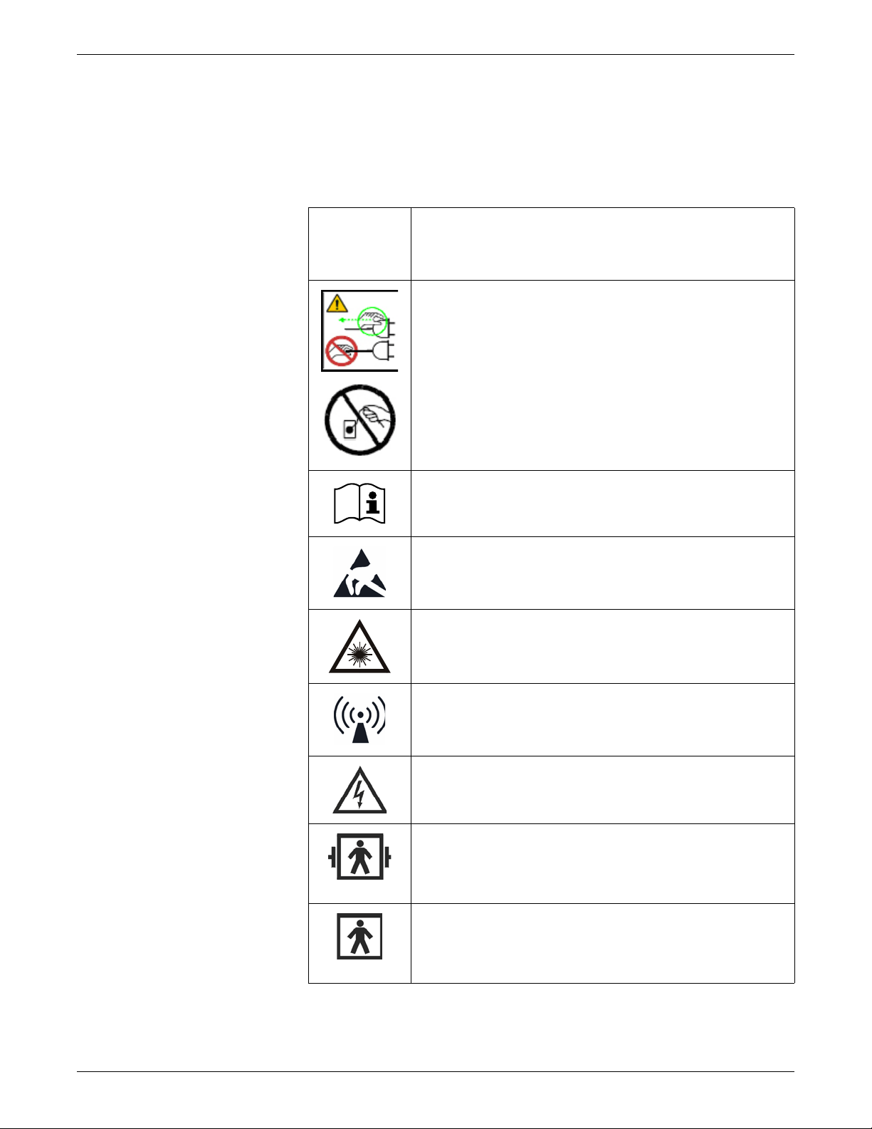
The following safety-related symbols appear on one or more of the devices.
ATTENTION: Consult accompanying documents.
CAUTION — Safety ground precaution. Remove power
cord from the mains source by grasping the plug. Do not
pull on the cable.
Consult operating instructions.
Electrostatic sensitive device. Connections should not be
made to this device unless ESD precautionary procedures
are followed.
LASER RADIA TION: Do not stare into beam. Class 2 laser
product.
Non-ionizing electromagnetic radiation. Interference may
occur in the vicinity of this device.
Shock Hazard. Dangerous voltage. To reduce the risk of
electric shock, do not remove cover. Refer servicing to
qualified service personnel.
Type BF (IEC 60601-1) defibrillator-proof protection
against electric shock. Isolated (floating) applied part
suitable for intentional external and internal application to
the patient, excluding direct cardiac application.
Type BF (IEC 60601-1) protection against electric shock.
Isolated (floating) applied part suitable for intentional
external and internal application to the patient, excluding
direct cardiac application.
1-16 CARESCAPE Monitor B850 2040384-004D
Page 23
User interface symbols
NOTE
The following symbols appear in the software user interface.
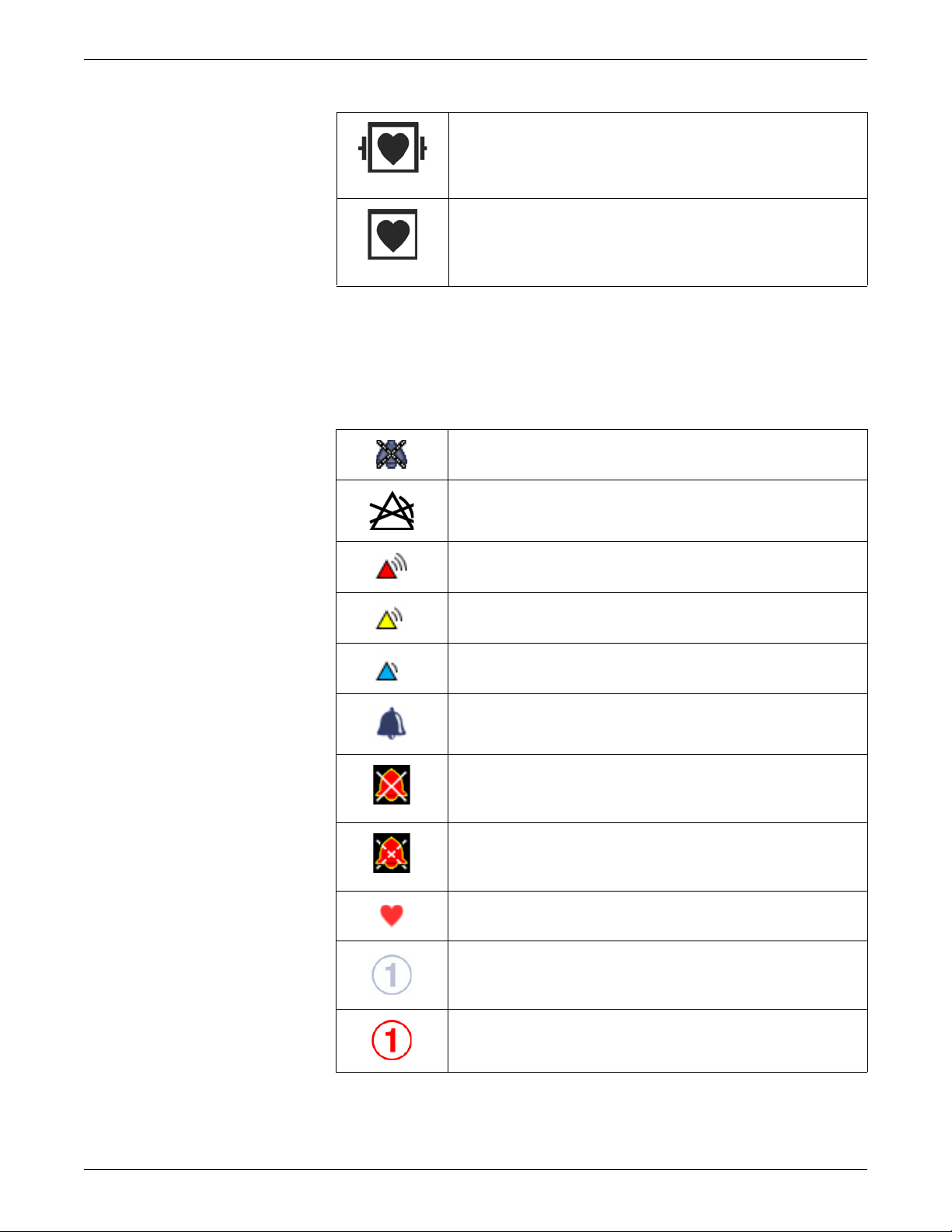
Type CF (IEC 60601-1) defibrillator-proof protection
against electric shock. Isolated (floating) applied part
suitable for intentional external and internal application to
the patient, including direct cardiac application.
Type CF (IEC 60601-1) protection against electric shock.
Isolated (floating) applied part suitable for intentional
external and internal application to the patient, including
direct cardiac application.
Active audio alarms paused indicator. Indicates an active
audio alarm is temporarily paused.
Alarm off indicator. Indicates the alarm is disabled (turned
off).
Alarm priority indicator: High (red). Indicates a high priority
alarm.
Alarm priority indicator: Medium (yellow). Indicates a
medium priority alarm.
Alarm priority indicator: Low (blue). Indicates a low priority
alarm.
Alarm volume icon. Adjust the minimum alarm tone
volume.
Audio alarms off indicator. Indicates the specified alarm
group (ALL, APN, APN ECG or ECG) audio alarms are
turned off.
Audio alarms paused indicator. Indicates all audio alarms
are paused and the amount of time remaining for the alarm
pause period displays as a countdown timer.
Beat volume icon. Adjust the volume of the QRS beep
tone.
BIS and Entropy sensor impedance check indicator.
Displays for each sensor as the impedance check is in
progress.
BIS and Entropy sensor impedance check error indicator.
Indicates the specified sensor failed the impedance check.
2040384-004D CARESCAPE Monitor B850 1-17
Page 24
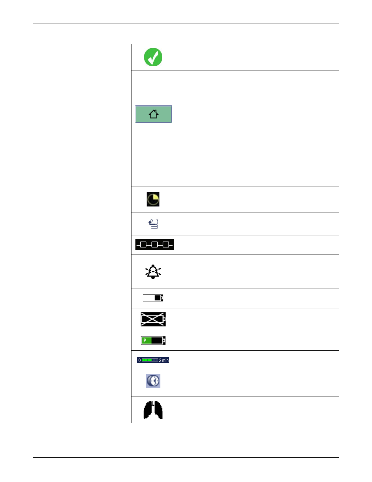
BIS and Entropy sensor impedance check passed
indicator. Indicates the specified sensor passed the
impedance check.
Completed NIBP volume icon. Adjust the volume of the
tone that sounds when an NIBP measurement result is
available.
Home icon. Close all menus/applications displayed on the
monitor.
Locking setting indicator. Indicates this setting is locked
and cannot be adjusted.
Manual NIBP icon. Start a manual NIBP measurement.
Nellcor OxiMax SatSeconds indicator. Indicates the
amount of time the SpO2 saturation is outside the limits
before alarms are generated.
NMT Stimulus beep vo lum e icon. Ad just the vo lume of the
tone that sounds when a stimulus pulse is generated.
Network connection indicator. Indicates the monitor is
connected to the Local Area Network (LAN).
Pause audio alarms icon. Selecting this option results in
different silence alarm behaviors depending whether
alarms are active and/or latched or not. For more
information, refer to the user’s manual.
PDM battery charging indicator. Indicates the battery is
charging.
PDM battery failure indicator. Indicates the battery is not
available for use.
PDM battery gauge indicator. Indicates the charge level of
the battery.
Progress bar. Indicates the amount of time remaining until
the next automatic measurement.
Reminder volume icon. Adjust the volume of the tone that
sounds every two minutes when audio alarms are turned
off.
Respiration indicator . Indicates a breath is detected by the
impedance respiration algorithm.
1-18 CARESCAPE Monitor B850 2040384-004D
Page 25
Service information
Service requirements
Follow the service requirements listed below.
Refer equipment servicing to GE authorized service personnel only.
Any unauthorized attempt to repair equipment under warranty voids that
It is the user’s responsibility to report the need for service to GE or to one of their
Failure on the part of the responsible individual, hospital, or institution using this
Regular maintenance, irrespective of usage, is essential to ensure that the
Snapshot indicator. Indicates the event has an associated
snapshot.
SpO2 signal strength indicator. Indicates the signal
strength, with three asterisks indicating the strongest
signal.
Touch volume icon. Adjust the volume of the tone that
sounds when a user touches a touchscreen display.
warranty.
authorized agents.
equipment to implement a satisfactory maintenance schedule may cause undue
equipment failure and possible health hazards.
equipment will always be functional when required.
2040384-004D CARESCAPE Monitor B850 1-19
Page 26

Page 27
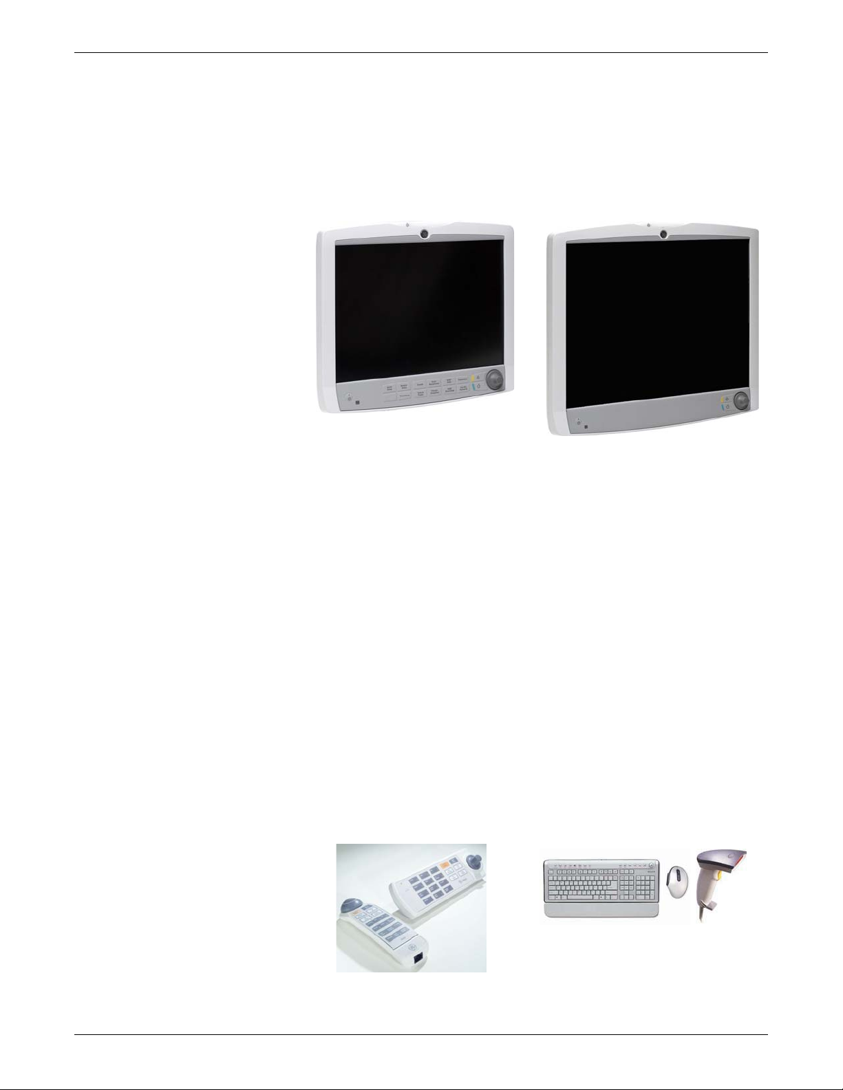
Displays
Displays integrate auditory and visual alarms and are available in 15-inch non-touch
or 19-inch touch LCD with integrated keypads. Both displays include an integrated
alarm light.
15-inch non-touch LCD 19-inch touch LCD
Refer to the “CARESCAPE Monitor B850 Addendum for Device Compatibility” for
a list of compatible devices.
Input devices
Input devices include remote control, keypad, keyboard, mouse and barcode reader.
The remote control and keypad provide all patient monitor controls on a portable
component with a TRIM KNOB control. The remote control is connected to the
patient monitor via one of the USB connectors at the back of the processing unit
or at the bottom of the display. The keypad is connected to an M-port and can be
mounted on the display or on a separate holster that has various mounting
configurations.
A standard keyboard and mouse may be connected to the patient monitor or
display via one of the USB connectors on the back of the processing unit or at the
bottom of the display.
The barcode reader, which may be connected to the patient monitor or display via
one of the USB connectors on the back of the processing unit or at the bottom of
the display, can be used to scan patient data from barcodes when admitting
patients.
2-4 CARESCAPE Monitor B850 2040384-004D
Page 28
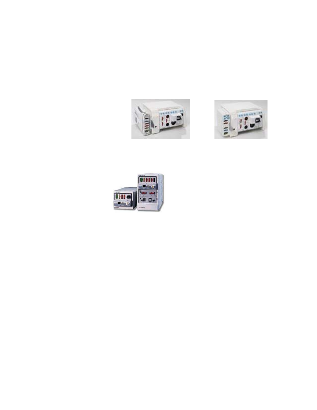
Refer to the “CARESCAPE Monitor B850 Addendum for Device Compatibility” for
PDM with F5 Frame
PSM with F5 Frame
a list of compatible devices.
Module Frames and Tram-Rac housing
F5 and F7 Module Frames provide an interface between the patient monitor and EModules. The F5 Module Frame has 5 module slots that support a series of E-module
acquisition devices. It supports both PDM and PSM with a slide mount. The F7
Module Frame has 7 module slots.
The Tram-Rac housing provides an interface between the patient monitor and a
TRAM module or a single parameter Tram-Rac module.
Acquisition modules
E-Modules and PDM
Refer to the “CARESCAPE Monitor B850 Addendum for Device Compatibility” for
a list of compatible devices and parameters monitored by PDM, each E-module,
TRAM module and single parameter Tram-Rac module.
Hemodynamic multi parameter acquisition modules are the Patient Data Module
(PDM), Patient Side Modules (PSM), E-PRESTN and TRAM modules. They provide
connection to the patient, process patient data signals, and send patient data signals to
the patient monitor.
Refer to the “CARESCAPE Monitor B850 Addendum for Device Compatibility” for
a list of compatible devices and parameters monitored by PDM, each E-module,
TRAM module and single parameter Tram-Rac module.
E-modules and the PDM offer a wide variety of parameter acquisition capability to
the patient monitoring system. Refer to the “Module Frames and Modules Technical
Manual” for detailed information on each E-module and the PDM.
2040384-004D CARESCAPE Monitor B850 2-5
Page 29

Page 30

2-10 CARESCAPE Monitor B850 2040384-004D
Page 31

3 Hardware installation
2040384-004D CARESCAPE Monitor B850 3-1
Page 32

Installation requirements
Environmental
For information about the operating environment for the patient monitor, refer to
“Intended use” on page 1-2.
Check the “CARESCAPE Monitor B850 Technical Specifications Supplement” for
power, temperature and operating conditions requirements.
Pre-installation
Make sure the following is in place before installing the patient monitoring system
hardware.
Power outlets that meet the required power specifications for each of the
following:
patient monitor
each display
powered Tram-Rac housing
Unity Network ID and each interface device
PRN 50-M digital writer
Network port for CARESCAPE Network Mission Critical (MC) or S/5 Network
Network port for CARESCAPE Network In formation Exchange (IX)
Mounting hardware for the monitor, display(s) and acquisition modules
3-2 CARESCAPE Monitor B850 2040384-004D
Page 33

Mounting
Rotating GE logo
The patient monitor ships with a mounting plate on the bottom enclosure. This
facilitates all mounting options for the monitor. For details, refer to the mounting
instructions included with the mounting hardware.
For details about the available mounting solutions, refer to the Mounting Reference
Guide.
NOTE
The GE logo can be rotated for vertical mounting configurations.
Water shield
For vertical mounting configurations, a water shield is available. The water shield
lowers the probability of the ingress of fluids into the assembly. The shield can be
installed in two orientations and should be placed to ensure the top surface of the
patient monitor is protected. For details, refer to the installation instructions included
with the water shield.
2040384-004D CARESCAPE Monitor B850 3-3
Page 34

Connect system components
WARNING
INCOMPATIBLE DEVICES—Befo re connecting an interfacing
module to the device, verify compatibility. Verify the connectivity
of device interfaces before using the equipment. Verify the
compatibility of software versions before using the equipment.
WARNING
EXCESSIVE LEAKAGE CURRENT—When interfacing the
device with other equipment, the devices may only be
interconnected with each other or to parts of the system when it has
been determined by qualified biomedical personnel that there is no
danger to the patient, the operator, or the environment as a result.
WARNING
POWER SUPPLY—The device must be connected to a properly
installed power outlet with protective earth contacts only. If the
installation does not provide for a protective earth conductor,
disconnect the monitor from the power line. All devices of a system
must be connected to the same power supply circuit. Devices which
are not connected to the same circuit must be electrically isolated
when operated (electrically isolated RS232 interface).
WARNING
Do not under any circumstances remove the grounding conductor
from the power plug. Always check that power cord and plug are
intact and undamaged.
3-4 CARESCAPE Monitor B850 2040384-004D
Page 35

Power cords
Power cord
Network
USB 1-4
ePort/Tramnet
(1 and 2)
DVI-D 2
DVI-I 1
RS232
(1 and 2)
DVI-I 3 (optional -
only
for iPanel software)
Equipotential post
connection
Connect power cords to the mains power supply inlet and to a wall outlet on all
system components that require AC mains power input. Do not power on any devices.
NOTE
Rear panel connections
Refer to the figure below for the patient monitor rear panel connections.
Be sure that all power cords are securely connected and that they are routed
through the retaining clips, as applicable.
Be sure that the retaining clips are not damaged or broken, and that they are
securely attached to the device.
The following connectors are available for system components:
Four USB ports
T wo Ethernet network ports
Two serial RS232 ports
Two video display ports (a third optional port may also be available)
T wo ePort/Tramnet ports
2040384-004D CARESCAPE Monitor B850 3-5
Page 36

USB and serial port management
Proper function of serial or USB touchscreen displays is dependent on the usage of
the correct RS232 and USB ports on the patient monitor.
NOTE
The patient monitoring system only supports the D19KT and D15K displays with
respect to USB.
Refer to the following table when connecting your displays containing either USB or
serial touchscreens.
Display port Number of displays Touch interface ports
Displays
DVI-I 1
Display 1 USB 1 or RS232 1
Display 1 cloned USB 1 or RS232 1
DVI-D 2 Display 2 USB 2 or RS232 2
Display 3 USB 3
DVI-I 3
Display 3 cloned No touch interface available
Unused USB ports may be connected to other accessories such as keyboard, mouse,
barcode reader, or remote control.
If the D15K or D19KT displays are not used
If you are not using the D15K or D19KT displays, there are no restrictions on
connecting devices to USB ports.
The patient monitor can support up to three independent displays when equipped with
an optional third video card. The optional third video can only be used to support the
iPanel application. The patient monitor also supports two additional cloned displays
on the DVI-I 1 and DVI-I 3 ports. Cloned displays must be connected using a DVI-I
to DVI-D and VGA splitter and must support analog video.
Refer to the “CARESCAPE Monitor B850 Addendum for Device Compatibility” for
a list of compatible devices.
WARNING
Do not use the monitor without manufacturer approved mounting
attached.
3-6 CARESCAPE Monitor B850 2040384-004D
Page 37

1. Connect either an analog or digital display to DVI-I 1.
NOTE
Additional displays can be connected to DVI-D 2 or DVI-I 3.
DVI-D 2 only supports digital displays.
If only one display is connected, it must be connected to DVI-I 1.
2. If the display supports a serial touchscreen, connect the serial port of the display
to RS232 1 or RS232 2. For more information on which port to use, refe r to the
display port table on page 3-6.
3. If the display is a D15K or D19KT, connect the upstream USB port of the display
to USB 1, USB 2, or USB 3. For more information on which port to use, refer to
the display port table on page 3-6.
NOTE
A USB hub should not be used to connect the USB touchscreen to the patient
monitor.
NOTE
To prevent accidental disconnection and loss of display screen information,
firmly tighten the DVI connector screws into the DVI connector port.
4. If the displays contain a touchscreen, calibrate as follows:
a. Select Monitor Setup > Service Calibrations.
b. Log in with your service username and password and press Enter.
Username: biomed
Password: Change<space>Me
NOTE
Username and password are case sensitive.
2040384-004D CARESCAPE Monitor B850 3-7
Page 38

c. On the Service / Calibrations menu, select T ouch Screen. The Touch screen
calibration menu displays.
d. Touch the cross hair (+) in each corner of the screen.
NOTE
Repeat steps 4 and 6 whenever a new touchscreen display is connected.
5. If the third video card is licensed, configure it. Follow these steps:
a. Go to Monitor Setup > Default Setup > Care Unit Settings > Screens.
b. Under Show Applications, click on Screen 3.
6. Restart the patient monitor.
3-8 CARESCAPE Monitor B850 2040384-004D
Page 39

Remote displays
Type A plug
Type A
receptacle
NOTE
All installations should be compliant with IEC 60601-1-1 and local electrical
codes.
Non isolated communication lines
If complete isolation is not required, this method will provide th e most cost effectiv e
means of extending your USB installation. This type of installation should not be
used for connections to non-medically used rooms per IEC 60601-1-1.
Displays may be extended up to 15 meters from the patient monitor using the
following cables:
15-meter DVI-I cable (p/n 2042766-001)
The connections for the DVI-I cable are the same as any other video cable.
5-meter USB extender (p/n 2042768-001)
In the following example, two 5-meter USB extenders, plus a standard 5-meter USB
cable extend the remote display up to 15 meters from the patient monitor. See “Setup
instructions” on page 3-10 for instructions on setting up the remote display as shown
in the example.
NOTE
Only the display interface connections (video and USB connections) are shown.
Not all other connections are shown.
2040384-004D CARESCAPE Monitor B850 3-9
Page 40

Setup instructions
Type A USB ports
NOTE
Be sure that all cables are securely connected.
1. Connect the Type A plug of the first USB extender to one of the downstream
ports (Type A USB port) on the back of the patient monitor.
NOTE
If you are connecting a touchscreen display, see the display port table on
page 3-6 for details on which port to use.
2. Connect the Type A plug of the second USB extender to the Type A receptacle
on the first USB extender.
3. Connect the Type A plug of the standard USB cable to the Type A receptacle on
the second USB extender.
3-10 CARESCAPE Monitor B850 2040384-004D
Page 41

4. Connect the Type B plug of the standard USB cable to the upstream port (Type B
DVI-I connector
Type A USB
Type B USB port
Type A USB ports
M-Ports M1 - M4
LED
Non-medical grade displays
The patient monitor with a non-medical grade display, which is IEC 950-rated or
equivalent, meets UL and IEC specifications if a medical grade isolation transformer
is used. If a non-medical grade display is to be used, the configuration must meet the
IEC 60601-1-1 standard. Refer to IEC 60601-1-1 for requirements if using nonmedical grade displays in the patient environment.
USB port) on the bottom of the display.
Interface devices
1. Connect a USB keyboard, mouse, remote, or barcode scanner to available USB
ports.
2. Connect the following interface devices to an M-Port on the front panel:
Unity Network ID connectivity device
PRN 50-M
keypad
2040384-004D CARESCAPE Monitor B850 3-11
Page 42

Networks
MC or S/5 Network port
IX Network port
WARNING
MISSED ALARMS—Do not use with iCentral software with
Versions 5.0.2 and earlier or with Mobile Care Server with Version
5.2 and earlier.
WARNING
INCORRECT CALCULATIONS—Using the CARESCAPE
Monitor B850 with the Aware Gateway software version 1.4 or
earlier could result in incorrect patient height and weight
information. This could lead to incorrect drug dose calculations,
hemodynamic calculations, or oxygenation calculations. Prior to
installing the CARESCAPE Monitor B850, please contact the GE
Healthcare Aware Gateway HL7 Integratio n Engineering Team or
your GE Healthcare service representative to verify or update your
Aware Gateway configuration.
WARNING
EXCESSIVE LEAKAGE CURRENT—Connect only certified UL
60950/IEC 60950 equipment to the Ethernet MC or IX network RJ45 connections. This equipment may need to be used with a
separating device, isolation module or redundant grounding in
accordance with the medical system standard IEC/EN 60601-1-1 in
order to meet system leakage current requirements.
NOTE
Refer to the “CARESCAPE Monitor B850 Addendum for Device Compatibility”
for compatible CARESCAPE Network and S/5 Network devices.
1. Connect the MC Network or S/5 Network cable to the CARESCAPE Network
MC port on the device.
2. Connect an IX Network cable to the CARESCAPE Network IX port on the
device.
3-12 CARESCAPE Monitor B850 2040384-004D
Page 43

Frame and E-Modules
The patient monitor provides support to connect multiple parameter modules at a
time. The ePort and Tramnet ports allow connection of E-Module Frame, Tram-Rac
housing and PDM.
Configuration options
See the following table for possible configuration options. For detailed information
on compatibility, refer to the “CARESCAPE Monitor B850 Addendum for Device
Compatibility.”
ePort 1/Tramnet 1 connected devices
Tram-Rac
PDM
Tram-Rac
housing
housing
(AC Mains
powered)
F5
Frame
F7
Frame
PDM
Tram-Rac
housing
ePort 2/
Tramnet 2
connected
devices
Tram-Rac
housing
(AC Mains
powered)
F5 Frame X
F7 Frame X X
In the table above:
X = supported
Shaded = not supported
WARNING
ELECTRIC SHOCK - Do not use the F7 Frame for standalone
use. Ventilation holes on the F7 E-module Frame will be
covered only if installed within an Aisys, Avance, or Aespire
anesthesia machine.
XXXX
X
X
XX X XX
XX
Example: If a PDM is connected to ePort 2, you cannot connect a second PDM to
ePort 1. However, you can connect one of the following devices to ePort 1:
Tram-Rac housing
Tram-Rac housing (AC Mains powered)
F5 Frame
F7 Frame
2040384-004D CARESCAPE Monitor B850 3-13
Page 44

Procedure
1. Connect an F5 or F7 frame to ePort/Tramnet.
2. Connect the module. Refer to the following instructions:
“To install a PSM module to an F5 Frame” on page 3-14
“To install a PSM module to an F7 Frame” on page 3-15
“To install another E-series parameter module” on page 3-16
To install a PSM module to an F5 Frame
WARNING
Do not use identical measurement modules or modules that map a
measurement to the same channel or parameter window. If such
modules have been connected, remove the module that has been
most recently connected. You can also remove both modules and
re-connect the new module after five seconds.
Refer to the “CARESCAPE Monitor B850 Addendum for Device Compatibility” for
a list of compatible devices.
NOTE
To ensure proper grounding of the Frame, secure the cable connections by using
a screwdriver to fully seat all thumbscrews.
3-14 CARESCAPE Monitor B850 2040384-004D
Page 45

1. Connect a PSM module by aligning it with the insertio n gui des on the out side of
the frame. Push the module into the frame until it stops.
NOTE
An error message displays if an incompatible module is connected. Refer to
the “CARESCAPE Monitor B850 Addendum for Device Compatibility” for
details.
2. To remove the PSM module, pull the pull tab out and slide the module out of the
guides.
To install a PSM module to an F7 Frame
WARNING
Do not use identical measurement modules or modules that map a
measurement to the same channel or parameter window. If such
modules have been connected, remove the module that has been
most recently connected. You can also remove both modules and
re-connect the new module after five seconds.
Refer to the “CARESCAPE Monitor B850 Addendum for Device Compatibility” for
a list of compatible devices.
2040384-004D CARESCAPE Monitor B850 3-15
Page 46

1. Connect the PSM pole mount or frame mount cable to the back of the F7 Frame.
2. Connect the PSM module to the mount.
To install another E-series parameter module
WARNING
Do not use identical measurement modules or modules that map a
measurement to the same channel or parameter window. If such
modules have been connected, remove the module that has been
most recently connected. You can also remove both modules and
re-connect the new module after five seconds.
Refer to the “CARESCAPE Monitor B850 Addendum for Device Compatibility” for
a list of compatible devices.
1. With the module properly oriented, align the module insertion guide slot with the
insertion guide.
2. Push the module into the frame until it clicks.
NOTE
An error message displays if an incompatible module is connected. Refer to
the “CARESCAPE Monitor B850 Addendum for Device Compatibility” for
details.
3-16 CARESCAPE Monitor B850 2040384-004D
Page 47

3. To remove a parameter module, grasp it firmly, press the release lever on bottom
of module, and pull out of the guides.
To install a PDM module
WARNING
Do not use identical measurement modules or modules that map a
measurement to the same channel or parameter window. If such
modules have been connected, remove the module that has been
most recently connected. You can also remove both modules and
re-connect the new module after five seconds.
The PDM module can be connected directly to the patient monitor or it can be
mounted to F5 Frame insertion guides.
NOTE
PDM software v1.2 is required for use with CARESCAPE Monitor B850
software.
The PDM can not be installed to an F7 Frame.
Refer to the “CARESCAPE Monitor B850 Addendum for Device
Compatibility” for a list of compatible devices.
When the PDM is used without a battery, it is necessary to allow additional
time to power up. Do not interrupt the startup sequence by unplugging the
PDM.
To connect the PDM module to the patient monitor – Connect one end of the
ePort cable to the PDM and the other end of the ePort cable to the ePort/Tramnet
connector on the patient monitor.
2040384-004D CARESCAPE Monitor B850 3-17
Page 48

To connect the PDM module to an F5 Frame – Align the PDM with the insertion
guides on the outside of the frame. Push the module into the frame until it stops.
NOTE
An error message displays if an incompatible module is connected. Refer to
the “CARESCAPE Monitor B850 Addendum for Device Compatibility” for
details.
Tram-Rac housing and modules
The patient monitor provides support to connect multiple parameter modules at a
time. The ePort and Tramnet ports allow connection of E-Module Frame, Tram-Rac
housing and PDM.
NOTE
A Tram-Net hub is not supported.
3-18 CARESCAPE Monitor B850 2040384-004D
Page 49

Configuration options
See the following table for possible configuration options. For detailed information
on compatibility, refer to the “CARESCAPE Monitor B850 Addendum for Device
Compatibility.”
ePort 1/Tramnet 1 connected devices
Tram-Rac
PDM
Tram-Rac
housing
PDM XXXX
housing
(AC Mains
powered)
F5
Frame
F7
Frame
Tram-Rac
X
X
housing
ePort 2/
Tramnet 2
connected
devices
Tram-Rac
housing
(AC Mains
powered)
F5 Frame X
XX X XX
XX
F7 Frame X X
In the table above:
X = supported
Shaded = not supported
Example
If a PDM is connected to ePort 2, you cannot connect a second PDM to ePort 1.
However, you can connect one of the following devices to ePort 1:
Tram-Rac housing
Tram-Rac housing (AC Mains powered)
F5 Frame
F7 Frame
2040384-004D CARESCAPE Monitor B850 3-19
Page 50

To connect the Tram-Rac housing to an ePort/Tramnet
Approximately 26 mm (1 in)
ferrite blocks
ferrite blocks
connector
1. Install the ferrite blocks that came with the patient moni tor to bot h ends of the
Tram-Net cables.
a. Place one end of cable in the groove of the ferrite block, approximately 26
mm (1 in) from the end of the cable.
b. Press the sides of the block together until you hear a click. Make sure both
snap fingers are fully engaged, and they are flush against the housing.
c. Repeat steps a and b for the other end of the cable.
d. Repeat steps a-c for all Tram-Net cables.
2. Connect the Tram-Rac housing to an ePort/Tramnet connector with ferrite
blocks on the patient monitor.
NOTE
A TRAM module must always occupy the top position in the Tram-Rac
housing. Other modules are installed below it.
When using more than one Tram-Rac housing, one of the Tram-Racs must
have a power supply.
Make sure the Tram-Net cable has ferrite blocks on both ends.
3-20 CARESCAPE Monitor B850 2040384-004D
Page 51

To install a module
CAUTION
SIMUL TANEOUS CONNECTION OF TRAM AND PDM — The
patient monitor only supports patient monitoring from one primary
ECG acquisition device at a time. A Patient Data Module (PDM)
and a TRAM module cannot be used to monitor a patient at the
same time.
If a PDM is connected to the patient monitor when monitoring from
a TRAM module has already been established, a ‘CONNECTING’
message is displayed on the monitor.
If a TRAM module is connected to the patient monitor when
monitoring from a PDM has already been established, no parameter
or waveform data from the TRAM module is displayed.
NOTE
When switching between primary acquisition devices (e.g., TRAM module
to PDM, or PDM to TRAM module), the patient monitor will perform a
reconnection cycle that can last up to two minutes. During this cycle, there is
a loss of displayed parameters and waveform data.
NOTE
An error message displays if an incompatible module is connected. Refer to
the “CARESCAPE Monitor B850 Addendum for Device Compatibility” for
details.
1. Face the Tram-Rac housing and guide the back of the module into the
appropriate position.
2. Gently push the module into the housing. You will hear a click when the module
is fully inserted.
To remove a module:
1. Push the module into the Tram-Rac housing. This releases the module and makes
it easier to remove.
2. Press and hold the release levers found on each side of the front of the module.
3. Pull the module out about 15 cm (6 inches).
4. Grasp the module firmly with bot h hands and remove it. Do not try to hold the
module by the release levers.
The release levers for TRAM modules are recessed in the side of the protruding front
of the module.
2040384-004D CARESCAPE Monitor B850 3-21
Page 52

Page 53

Using a service PC over the network
1. Verify that the patient monitor is connected to a live IX Network.
2. Record the IP and Netmask addresses of the patient monitor:
Static IP address: ______________________
Netmask: ________________________
3. Verify that the service PC is on the same network as the patient monitor by
performing a network ping to the patient monitor. If needed, configure the
service PC’s IP and Netmask addresses.
4. From a computer connected to the same network as the patient monitor, launch a
web browser.
5. In the Address field, type https://[IX IP address]:10000 and press Enter.
NOTE
[IX IP address] is the IX Network IP address of the patient monitor.
The Login to Webmin dialog box displays.
6. Continue to “Log into Webmin” on page 4-4.
Using a service PC with a crossover cable
1. Verify that the IX Network on the patient monitor is configured in manual
configuration mode.
2. Record the IP and Netmask addresses of the patient monitor:
Static IP address: ______________________
Netmask: ________________________
3. Verify that the service PC’s network is configured in manual configuration mode
to allow communication with the patient monitor. If needed, configure the
service PC’s IP and Netmask addresses.
4. Verify that the service PC is able to perform a network ping to the patient
monitor. See “Ping a TCP/IP network device” on page 8-5.
5. Connect a correctly configured service laptop to the CARESCAPE Network IX
connection port on the patient monitor using a crossover cable.
2040384-004D CARESCAPE Monitor B850 4-3
Page 54

Page 55

4-6 CARESCAPE Monitor B850 2040384-004D
Page 56

Page 57

Admit settings
Patient ID prefix
3. On the MUSE/12SL window, enter the following:
MUSE Web Username
MUSE Web Password
Confirm Password
MUSE Web URL
4. Select Save.
The MUSE settings take effect immediately after they are submitted.
The patient ID prefix is used as the first two characters when generating temporary
patient IDs to ensure that the patient ID is unique.
1. If you have not already done so, “Log into Webmin” on page 4-4 and select the
Configuration tab.
2. On the Configuration tab, select Admit Settings.
3. On the Sub-Modules for Admit Settings menu, select Patient ID.
4. On the Patient ID Prefix window, enter a 2-character prefix.
Barcode settings
NOTE
Valid values are uppercase letters and numbers.
5. Select Submit.
All changes take effect immediately.
Barcode settings must be configured if a barcode reader is used to input patient data to
the Admit/Discharge menu.
NOTE
For details on barcode data requirements and restrictions, see “Barcode data
specifications” on page 4-19.
1. Select the parser type.
a. If you have not already done so, “Log into Webmin” on page 4-4 and select
the Configuration tab.
b. On the Configuration tab, select Admit Settings.
c. On the Sub-Modules for Admit Settings menu, select Barcode Settings.
d. Under Barcode Setup on the Barcode Settings window, select the applicable
4-14 CARESCAPE Monitor B850 2040384-004D
Page 58

parser type.
Parser type Used with this type of barcode
No Parser Simple barcode that contains one piece of
information, but no data control, so there is no
need for a parser.
Length Delimited Parser Barcode that specifies the beginning position and
length of each field on the barcode.
Character Delimited Parser Barcode that specifies a special character that
separates each field on the barcode.
2. Select Submit.
If you selected No Parser, the barcode setting configuration is complete.
For a Length or Character Delimited Parser, follow the applicable instructions.
“Configure length delimited parser information” on page 4-15.
or
“Configure character delimited parser information” on page 4-17.
Configure length delimited parser information
Points to note
If you configure Age, you must either select the Age Unit item or one of the age
units (e.g., Years, Months, Weeks, Days) under Fixed Option.
If you configure Height, you must either select the Height Unit item or one of
the height units (e.g., Feet, Inches, Meters, Centimeters, Millimeters) under
Fixed Option.
If you configure Weight, you must either select the Weight Unit item or one of
the weight units (e.g., Kilograms, Grams, Micrograms, Pounds, Ounces) under
Fixed Option.
For an example of admit/discharge configuration for a length delimited parser,
refer to “Sample length delimited parser information” on page 4-16.
1. On the Admit/Discharge Configuration window, enter the location and length
information for each data item.
If an item is not included in the barcode, type 0 in the item’s Position and Length
fields, or leave the Position and Length fields blank.
a. In the Position column, type the beginning position of the field in the data
string (from 1 to 300).
b. In the Length column, type the number of characters (from 1 to 99) that the
field contains.
2. For Gender Format, select Fixed or Configured.
If you select Configured:
a. Type the character that identifies Male.
2040384-004D CARESCAPE Monitor B850 4-15
Page 59

b. Type the character that identifies Female.
3. Under Fixed Option, select the applicable value:
Item
Item selection on the top part
of the screen
Fixed Option selection
Both Height and Height Unit Non-Fixed.
Height Unit
Height only Select value from drop down list.
Both Weight and Weight Unit Non-Fixed.
Weight Unit
Weight only Select value from drop down list.
Both Age and Age Unit Non-Fixed.
Age Unit
Age only Select value from drop down list.
4. Scroll to the bottom of the window, and sel ect Submit.
All changes take effect immediately.
Sample length delimited parser information – In this example, the barcode
contains 10 items. The following table lists the starting position and length of each
item
Item Starting Position Length
MRN 110
First Name 11 10
Last Name 21 15
Day of Birth 46 2
Month of Birth 48 2
Year of Birth 50 4
Age 36 5
Age Unit 41 5
Gender 54 1
Height 55 5
4-16 CARESCAPE Monitor B850 2040384-004D
Page 60

The following sample shows the corresponding entries on the Admit/Discharge
Configuration window.
Configure character delimited parser information
Points to note
If you configure Age, you must either select the Age Unit item or one of the age
units (e.g., Years, Months, Weeks, Days) under Fixed Option.
If you configure Height, you must either select the Height Unit item or one of
the height units (e.g., Feet, Inches, Meters, Centimeters, Millimeters) under
Fixed Option.
If you configure Weight, you must either select the Weight Unit item or one of
the weight units (e.g., Kilograms, Grams, Micrograms, Pounds, Ounces) under
Fixed Option.
For an example of admit/discharge configuration for a length delimited parser,
refer to “Sample character delimited parser information entry” on page 4-18.
1. In the Position column of the Admit/Discharge Configuration window, enter the
sequence number of each item included in the barcode. Use incremental numbers
from 1 (the left-most field) up to 16 (the right-most field).
If an item is not included in the barcode, leave the Position field blank for the
item.
2040384-004D CARESCAPE Monitor B850 4-17
Page 61

2. Under Field Delimiter, in the Delimiter field, enter the special character that
separates the fields on the barcode.
NOTE
Allowed characters are ASCII characters 33-126.
Forbidden characters are control characters (ASCII characters 0-31), the
space character (ASCII character 32), and ASCII characters 127 and above.
If the character selected exists in any field in the barcode, it will be
misinterpreted as a field delimiter.
3. Under Gender Code, enter the codes that identify Male and Female.
4. Under Fixed Option, select the applicable value:
Item
Item selection on the top part
of the screen
Fixed Option selection
Both Height and Height Unit Non-Fixed.
Height Unit
Height only Select value from drop down list.
Both Weight and Weight Unit Non-Fixed.
Weight Unit
Weight only Select value from drop down list.
Both Age and Age Unit Non-Fixed.
Age Unit
Age only Select value from drop down list.
5. Scroll to the bottom of the window, and sel ect Submit.
All changes take effect immediately.
Sample character delimited parser information entry – In the following example,
the barcode contains 12 items and uses the pound sign (#) as a delimiter.
Item Sequence number of the item in the barcode
MRN 4
First Name 5
Last Name 6
Day of Birth 1
Month of Birth 2
Year of Birth 3
Age 11
Age Unit 12
Gender 7
Height 8
4-18 CARESCAPE Monitor B850 2040384-004D
Page 62

Item Sequence number of the item in the barcode
Height Unit 9
Weight 10
The following sample shows the corresponding entries on the Admit/Discharge
Configuration window.
Barcode data specifications
Points to note
The maximum length of the entire barcode is 300.
If the field value is longer than the maximum length indicated, the right-most
characters will be truncated when the value is displayed on the Admit/Discharge
menu.
If a field contains a forbidden character, that character will be replaced with a
space when it is displayed on the Admit/Discharge menu.
2040384-004D CARESCAPE Monitor B850 4-19
Page 63

Item
Maximum
length
Valid entries Comments
MRN 99
Forbidden characters are those that are not allowed by the
First Name 99
Last Name 99
Both letters and numbers
monitor, including the following characters:
! " # ¤ % & /( ) = ? ` @ £ $ € { [ ] } \ * ^ _ : ; | < >
Day of Birth 2 1-31 If Day of Birth is present in the barcode, then Month of Birth
and Year of Birth also need to be present.
Month of Birth 2 1-12 If Month of Birth is present in the barcode, then Day of Birth
and Year of Birth also need to be present.
Year of Birth 4 1880 to current year If Year of Birth is present in the barcode, then Day of Birth
and Month of Birth also need to be present.
Age 99 Numeric 9999.9999 Either a period or comma is accepted as a decimal symbol.
Age Unit 99
A, Y, YR, YRS (years)
MO, MOS (months)
WK, WKS (weeks)
D, DAY, DYS (days)
Gender 1 If gender is configured (not fixed), this must be 1 character.
Height 99 Numeric 9999.9999 Either a period or comma is accepted as a decimal symbol.
Height Unit 99
FT (feet)
IN (inches)
M (meters)
CM (centimeters)
MM (millimeters)
Weight 99 Numeric 9999.9999 Either a period or comma is accepted as a decimal symbol.
Weight Unit 99
Visit Number 99
Primary Physician 99
KG, KGS (kilograms)
G, GM, GMS (grams)
MCG (micrograms)
OZ, OZS (ounces)
LB, LBS (pounds)
Both letters and numbers
Forbidden characters are those that are not allowed by the
monitor, including the following characters:
! " # ¤ % & /( ) = ? ` @ £ $ € { [ ] } \ * ^ _ : ; | < >
Referring Physician 99
4-20 CARESCAPE Monitor B850 2040384-004D
Page 64

Power frequency
Language
WARNING
Incorrect power line frequency setting could adversely affect ECG
and EEG processing.
1. If you have not already done so, “Log into Webmin” on page 4-4 and select the
Configuration tab.
2. On the Configuration tab, select Power Frequency.
3. On the Power Frequency window, select the applicable power line frequency.
4. Select Submit.
The power frequency changes take effect after the next system restart.
1. If you have not already done so, “Log into Webmin” on page 4-4 and select the
Configuration tab.
2. On the Configuration tab, select Language.
National requirements
3. On the Language window, select the patient monitor language and keyb oard
language:
a. Select the monitor language from the drop-down list and select Submit.
b. Select the keyboard locale from the drop-down li st and select Submit.
4. Select Submit.
The language takes effect after the patient monitor is restarted.
Select the national requirements for the system.
1. If you have not already done so, “Log into Webmin” on page 4-4 and select the
Configuration tab.
2. On the Configuration tab, select National Requirements.
2040384-004D CARESCAPE Monitor B850 4-21
Page 65

Host asset settings
3. On the National Requirement window, select the applicable option:
Value Description
None Select the normal defaults.
France Enable the following country specific monitoring:
At least 1 audible and visual occurrence must remind either
as an un-inhibitable audible and visual alarm or as an
audible and recurring recall repeated at least every 3
minutes and also inhibitable.
Heart Rate high alarm limit maximum 230 instead of 250.
Reminder beep will sound every 2 minutes when alarms
have been silenced permanently.
4. Select Submit.
The national requirements changes take effect after the next system restart.
NOTE
The Host Serial Number field is view only and cannot be changed.
To set the host asset number:
Modules
Asset settings
1. If you have not already done so, “Log into Webmin” on page 4-4 and select the
Configuration tab.
2. On the Configuration tab, select Host Asset Settings.
3. On the Host Asset Settings window, enter the user-assigned host asset number in
the Change Value to column.
4. Select Submit.
The host asset changes take effect immediately.
NOTE
This configuration applies only to the PDM.
The Device Serial Number field is view only and cannot be changed.
To set the device asset number of a PDM:
1. If you have not already done so, “Log into Webmin” on page 4-4 and select the
Configuration tab.
2. On the Configuration tab, select Modules.
3. On the Sub-Modules for Modules menu, select Assets Settings.
4. On the Assets Settings window, enter the user-assigned asset number for the
device in the Change Value to column.
4-22 CARESCAPE Monitor B850 2040384-004D
Page 66

Licensing
5. Select Submit.
The change will take effect immediately.
NOTE
This configuration applies only to the PDM.
To activate the license for a PDM:
1. If you have not already done so, “Log into Webmin” on page 4-4 and select the
Configuration tab.
2. On the Configuration tab, select Modules.
3. On the Sub-Modules for Modules menu, select Licensing.
4. On the Licensing window, enter the activation code by the appropriate feature.
5. Select Activate.
NOTE
To remove the license, select Remove next to the feature you want to
remove.
6. After adding and activating the license(s), perform the appropriate parameter
checkout.
ECG filter configuration
The changes will take effect after the PDM is power-cycled.
NOTE
This configuration applies only to the PDM.
The ECG Filter is always enabled. It can be disabled temporarily, but it will always
default to an enabled state after a power cycle or reboot of the PDM.
CAUTION
Do not disable the ECG Filter during clinical use.
To set the acquisition ECG filter for the PDM:
1. If you have not already done so, “Log into Webmin” on page 4-4 and select the
Configuration tab.
2. On the Configuration tab, select Modules.
3. On the Sub-Modules for Modules menu, select ECG Filter Configuration.
4. On the ECG Filter Configuration window, select the applicable radio button to
Enable or Disable the line frequency filter.
5. Select Submit.
The change will take effect immediately.
2040384-004D CARESCAPE Monitor B850 4-23
Page 67

STP/TP/ST settings
P/PT/PP settings
NOTE
This procedure applies to the E-PRESTN, E-PRETN, E-RESTN, E-PSM and EPSMP modules (which use SpO2, invasive pressure or temperature
measurements) and is needed after corrective maintenance only. For more
information, refer to the “Module Frames and Modules Technical Manual”.
1. If you have not already done so, “Log into Webmin” on page 4-4 and select the
Configuration tab.
2. On the Configuration tab, select Modules.
3. On the Sub-Modules for Modules menu, select STP/TP/ST Settings.
4. Select a new configuration from the New Configuration drop down list.
5. Select Submit.
The changes will take effect after the patient monitor is restarted.
NOTE
This procedure applies to the E-P, E-PT, and E-PP modules (which use invasive
pressure or temperature measurements) and is needed after corrective
maintenance only. For more information, refer to the “Module Frames and
Modules Technical Manual”.
Passwords
1. If you have not already done so, “Log into Webmin” on page 4-4 and select the
Configuration tab.
2. On the Configuration tab, select Modules.
3. On the Sub-Modules for Modules menu, select P/PT/PP Settings.
4. Select a new configuration from the New Configuration drop down list.
5. Select Submit.
The changes will take effect after the patient monitor is restarted.
WARNING
Control of this user’s password is critical to ensure that Webmin on
this device is accessed by only trained and authorized personnel.
Failure to limit access of Webmin to trained and authorized
personnel only may compromise patient safety and/or system
performance.
1. If you have not already done so, “Log into Webmin” on page 4-4 and select the
Configuration tab.
2. On the Configuration tab, select Passwords.
4-24 CARESCAPE Monitor B850 2040384-004D
Page 68

Remote service
Configuration
3. On the Edit User Password window, change the biomed or clinical user’s
password as required.
4. Select Save.
The change will take effect immediately.
If the site uses an http proxy server, its address and port must be specified for remote
service communication to work.
1. If you have not already done so, “Log into Webmin” on page 4-4 and select the
Configuration tab.
2. On the Configuration tab, select Remote Service.
3. On the Sub-Modules for Remote Service menu, select Configuration.
4. On the Remote Service Configuration window, enter the applicable data:
HTTP Proxy Server Configuration
Item Description Comments
Address
Port
Username and
Password
Item Description Comments
System ID Identifies the system to the GE
Serial Number Identifies the unit and is set at the
If this site uses an HTTP proxy
server, a specific site proxy
server IP Address and Port
number are required for the
Remote Service
communication to work.
Otherwise, select None.
If the HTTP proxy server
requires user authorization, a
specific Username, and
Password is required.
Otherwise, select None.
Remote Service Configuration
backoffice servers.
time of manufacture.
These values are
determined by the
customer.
These values are read-only
and are unique.
2040384-004D CARESCAPE Monitor B850 4-25
Page 69

Remote Service Configuration
Item Description Comments
Enterprise URL If required, designate the address
of the GE backoffice servers
required to communicate with the
Remote Service Agent.
Enterprise Tunnel
URL
If required, designate the address
of the GE backoffice servers
required to communicate with the
tunneling agent.
This address should never
be changed unless explicit
instructions are given to do
so.
Control
Protocol Identifies the protocol used to
communicate with the enterprise
servers.
5. Select Save.
The changes will take effect immediately.
After the server has been configured for remote serviceability, the remote service
agent must be enabled for use.
NOTE
Be sure that you have read and understood all associated InSite 2.0
documentation, including “Remote service” on page 4-25. By enabling Remote
Service, you are enabling supported Remote Service features for this device.
1. If you have not already done so, “Log into Webmin” on page 4-4 and select the
Configuration tab.
2. On the Configuration tab, select Remote Service.
3. On the Sub-Modules for Remote Service menu, select Control.
4. Under Remote Service Control on the Remote Service Control window, enable
or disable the Service Agent by selecting Enable or Disable.
This field is read-only and
cannot be changed.
5. Select Save.
The changes will take effect immediately.
4-26 CARESCAPE Monitor B850 2040384-004D
Page 70

Settings
The patient monitor allows the end-user to archive the clinical and platform settings
to external media. By logging in remotely from a computer to the patient monitor
through Webmin, the end-user can save or load the archived settings. See the
following table for detailed settings information.
Type of setting Configuration information that can be saved or loaded
Save settings
Platform settings
Clinical settings
Admit settings
Citrix
Host asset numbers
Host license
Language
MUSE/12SL
National requirement
Network
Password
Power frequency
Printers
Remote service
Time
Unit and bed name
Care unit settings
Profile settings
NOTE
This option is available only when you log into Webmin remotely. The option is
not available locally at the patient monitor.
1. If you have not already done so, “Log into Webmin” on page 4-4 and select the
Configuration tab.
2. On the Configuration tab, select Settings.
3. On the Sub-Modules for Settings menu, select Save.
4. On the Save Settings window, select the radio button next to th e type of setti ngs
you want to save.
5. Select Save.
2040384-004D CARESCAPE Monitor B850 4-27
Page 71

Load settings
Activate settings
NOTE
This option is available only when you log into Webmin remotely. The option is
not available locally at the patient monitor.
1. If you have not already done so, “Log into Webmin” on page 4-4 and select the
Configuration tab.
2. On the Configuration tab, select Settings.
3. On the Sub-Modules for Settings menu, select Load.
4. On the Load Settings window, enter the file name or click on Browse to select a
file from the Choose file dialog box.
5. Select Upload to load the settings.
When the settings are activated, monitors configured for the U.S. will revert to the
international factory default settings. To reload the U.S. factory default settings, use
the U.S. defaults CD and follow the procedure to “Load settings” on page 4-28.
NOTE
The patient monitor needs to be in a discharged state.
Software Management
1. Log on to Webmin.
2. Select the Configuration tab.
3. On the Configuration tab, select Settings.
4. On the Sub-Modules for Settings menu, select Activate
5. On the Activate Settings window, select the settings that you want to activate.
6. Select Submit.
The changes will take effect after the patient monitor is restarted.
For information, refer to the “CARESCAPE Monitor B850 Soft ware Installation
Instructions”.
.
4-28 CARESCAPE Monitor B850 2040384-004D
Page 72

5 Installation checkout
2040384-004D CARESCAPE Monitor B850 5-1
Page 73

Overview
Visual inspection
The purpose of this installation checkout procedure is to ensure that the system is
properly installed and configured for use. Record all checkouts performed using the
“Check form” on page B-3, or equivalent.
The patient monitor and its components should be carefully inspected every 12
months, and each time the equipment is serviced.
Carefully inspect the device for any damage.
Carefully inspect any devices connected to the following ports: M-ports, RS232,
DVI, USB and e-Port/Tramnet.
Carefully inspect all cables connected to all ports, including the MC Network and
IX Network ports.
Verify that the power cord and USB cables are properly secured with the supplied
retaining clips.
Verify that ferrite blocks are installed on all Tram-Net cables. See page 3-20 for
details.
5-2 CARESCAPE Monitor B850 2040384-004D
Page 74

Electrical safety tests
Electrical safety tests provide a method of determining if potent ial electrical health
hazards to the patient or operator of the device exist.
Recommendations
Qualified personnel must perform all safety tests presented in this section.
Upon receipt of the device (patient monitor and its associated equipment). Refer
to “Installation checkout procedure” on page 5-16 for more information.
Every 12 months thereafter (planned maintenance). Refer to “Maintenance
schedule” on page 7-2 for more information.
Each time the main enclosure is disassembled or a circuit board is removed,
tested, repaired, or replaced (corrective maintenance). Refer to “Recommended
checkout” on page 9-10 and 9-20.
Record the values of each required electrical safety test in the “Check form” on
page B-3, or equivalent.
These instructions are intended for every component in the system. If the Tram-Rac
housing does not have its own power supply, it should remain connected to the patient
monitor throughout the safety tests.
WARNING
Only perform maintenance procedures specifically described in the
manual.
WARNING
Preventive maintenance should be carried out annually. Failure to
implement the recommended maintenance schedule may cause
equipment failure and possible health hazards.
NOTE
The manufacturer does not, in any manner, assume the responsibility for
performing the recommended maintenance schedule, unless an Equipment
Maintenance Agreement exists. The sole responsibility rests with the individuals,
hospitals, or institutions utilizing the device.
2040384-004D CARESCAPE Monitor B850 5-3
Page 75

Test equipment
The recommended test equipment required to perform electrical safety tests is listed
below.
Item Specification
Leakage Current Tester Equivalent to the circuits shown
Setup
Digital Multimeter (DMM) (optional based on leakage
tester used and locality)
Ground Bond Tester (if required by local regulations) 0 – 1 ohm
Safety Test Body Kit
1.
Instead of the test bodies in the safety test body kit, other applicable test bodies with
pins connected together may be used.
Perform electrical safety tests using an electrical safety analyzer per IEC 60601-1, UL
60601-1, EN 60601-1 or CSA C22.2 No. 601.1. The schematics in this section
provide a general understanding of the test equipment. Actual configuration of test
equipment may vary.
The patient monitor being tested should be placed on an insulating surface.
NOTE
Before proceeding, make sure that all test equipment is properly calibrated and
functioning.
Ensure that all the system components are correctly connected as described in
“Connect system components” on page 3-4.
1
AC volts, ohms
P/N M1155870 or equivalent
Power outlet test
Verify that the power outlet is wired correctly per the country’s electrical code
standard before starting the following electrical safety tests. The results of the
following tests will be inaccurate unless a properly wired power outlet is used. Use
only non-isolated power outlets when performing safety tests.
Power cord and plug
Verify the power cord being used with the patient monitor is good. The following are
a couple of things to check for in this regard:
Inspect the power cord for wear or damage regularly. If damage is suspected, test
for continuity through each conductor of the power cord connector.
Verify line, neutral, and earth cond uctors are properly connected to the power
cord plug and are not short-circuited. Replace the power cord, as necessary, with
5-4 CARESCAPE Monitor B850 2040384-004D
Page 76

Page 77

4. Change leakage tester switches to:
Polarity – NORMAL
Neutral – OPEN
GND (Earth) – CLOSED
5. Read and record the current leakage indicated on the tester.
6. Change leakage tester switches to:
Polarity – REVERSE
Neutral – OPEN
GND (Earth) – CLOSED
7. Read and record the current leakage indicated on the tester.
8. Change leakage tester switches to:
Polarity – REVERSE
Neutral – CLOSED
GND (Earth) – CLOSED
9. Read and record the current leakage indicated on the tester.
If measured reading is greater than the appropriate specification below, the device
under test fails. Contact GE Technical Support.
Acceptance criteria normal condition (NC)
(USA only) 300 µA, and the device under test is powered from 100-120 VAC/50-
60 Hz
(USA only) 300 µA, and the device under test is powered from a center-tapped
200-240 VAC/50-60 Hz, single phase circuit (UL Split Phase Exemption)
500 µA, and the device under test is powered from a non-center-tapped, 200-240
VAC/50-60 Hz, single-phase circuit
Acceptance criteria single fault condition (SFC) – ground (earth), line or neutral
open
(USA only) 300 µA, and the device under test is powered from 100-120 VAC/50-
60 Hz
(USA only) 300 µA, and the device under test is powered from a center-tapped
200-240 VAC/50-60 Hz, single phase circuit (UL Split Phase Exemption)
1000 µA, and the device under test is powered from a non-center-tapped, 200-
240 VAC/50-60 Hz, single-phase circuit
NOTE
Center-tapped and non-center-tapped supply circuits produce different leakage
currents and the UL and IEC limits are different.
2040384-004D CARESCAPE Monitor B850 5-7
Page 78

Enclosure (touch) leakage current test
Perform this test to measure current leakage through exposed conductive surfaces on
the device under test during normal operation. Refer to the instructions contained
with the safety analyzer to perform enclosure leakage current test.
NOTE
*The MD represents the network and voltage measuring instrument and its
frequency characteristics per IEC 60601-1.
1. Configure leakage tester as follows:
Polarity – NORMAL
Neutral – CLOSED
GND (Earth) – CLOSED
2. Power on device under test.
3. Read and record the current leakage indicated on tester.
NOTE
Center-tapped and non-center-tapped supply circuits produce different
leakage currents and the UL and IEC limits are different.
4. Change leakage tester switches to:
Polarity – NORMAL
Neutral – OPEN
GND (Earth) – CLOSED
5. Read and record the current leakage indicated on the tester.
6. Change leakage tester switches to:
Polarity – NORMAL
Neutral – CLOSED
GND (Earth) – OPEN
7. Read and record the current leakage indicated on the tester.
8. Change leakage tester switches to:
Polarity – REVERSED
Neutral – CLOSED
GND (Earth) – OPEN
5-8 CARESCAPE Monitor B850 2040384-004D
Page 79

Acceptance criteria NC
9. Read and record the current leakage indicated on the tester.
10. Change leakage tester switches to:
Polarity – REVERSED
Neutral – OPEN
GND (Earth) – CLOSED
11. Read and record the current leakage indicated on the tester.
12. Change leakage tester switches to:
Polarity – REVERSED
Neutral – CLOSED
GND (Earth) – CLOSED
13. Read and record the current leakage indicated on the tester.
14. Set the power switch of the device under test to OFF.
If measured reading is greater than the appropriate specification below, the device
under test fails. Contact GE Technical Support.
100 microamperes (0.1 volts on the tester), and the device under test is powered
from 100-240 VAC/50-60 Hz
Acceptance criteria SFC - ground (earth), line or neutral open
(USA only) 300 µA, and the device under test is powered from 100-120 VAC/50-
60 Hz
(USA only) 300 µA, and the device under test is powered from a center-tapped
200-240 VAC/50-60 Hz, single phase circuit (UL Split Phase Exemption)
500 µA, and the device under test is powered from a non-center-tapped, 200-240
VAC/50-60 Hz, single-phase circuit
NOTE
If any reading is outside the indicated acceptance criteria, contact GE Technical
Support for service.
Patient leakage current tests
The following table lists all the modules and module connections to be tested in the
patient source and patient sink leakage tests.
Use the safety test body kit (P/N M1155870 or equivalent) for all modules. This kit
contains various safety test bodies for use with different parameters.
NOTE
Alternatively, you may use a corresponding test body with pins connected
together.
2040384-004D CARESCAPE Monitor B850 5-9
Page 80

For information on which test body to use for each parameter, refer to the instructions
for use included in the safety test body kit.
Module Patient connector
E-BIS Test from DSC BIS connector
E-COP, E-COPSv P4/P8
E-EEG EEG
E-ENTROPY Entropy
Test from Entropy cable
E-MASIMO SpO2
E-NMT NMT
E-NSAT SpO2
E-NSATX SpO2
E-P, E-PT P3/P7
E-PP P5-P6
E-PRESTN, PSMP ECG
SpO2
E-PRETN ECG
P1-P2
E-RESTN, PSM ECG
SpO2
M-BIS Test from DSC BIS connector
M-COP, M-COPSv P4
M-EEG EEG
M-ENTROPY Entropy
Test from Entropy cable
M-NMT NMT
M-NSAT SpO2
M-P, M-PT P3
M-PP P5-P6
M-PRESTN ECG
SpO2
M-PRETN ECG
P1-P2
M-RESTN ECG
SpO2
5-10 CARESCAPE Monitor B850 2040384-004D
Page 81

Module Patient connector
Masimo SpO2 SpO2
PDM ECG
SpO2
SpO2 SpO2
TRAM 250SL ECG
SpO2
TRAM 450SL ECG
SpO2
TRAM 451 ECG
SpO2
TRAM 451M ECG
SpO2
TRAM 451N ECG
SpO2
TRAM 451N5 ECG
SpO2
TRAM 850SL ECG
SpO2
TRAM 851 ECG
SpO2
TRAM 851M ECG
SpO2
TRAM 851N ECG
SpO2
TRAM 851N5 ECG
SpO2
2040384-004D CARESCAPE Monitor B850 5-11
Page 82

Patient (source) leakage current test
This procedure only applies to Class I (grounded/earthed) equipment, and measures
the leakage current from the ECG/RESP connector or the SPO2 connector of the
device to ground.
This procedure applies to all parameter modules connected to the patient monitor. For
each module, test only those patient connections that are listed in the table on page 5-
9.
NOTE
*The MD represents the network and voltage measuring instrument and its
frequency characteristics per IEC 60601-1.
The patient connector test body shorts all signals in the connector together. Refer to
the instructions contained with the safety analyzer to perform this test.
1. Connect the ECG/RESP test body to the green connector of the device under test.
2. Configure leakage tester as follows:
Polarity – NORMAL
Neutral – CLOSED
GND (Earth) – CLOSED
3. Power on device under test.
4. Read and record the current leakage indicated on the tester.
5. Change leakage tester switches to:
Polarity – NORMAL
Neutral – OPEN
GND (Earth) – CLOSED
6. Read and record the current leakage indicated on the tester.
7. Change leakage tester switches to:
Polarity – NORMAL
Neutral – CLOSED
GND (Earth) – OPEN
8. Read and record the current leakage indicated on the tester.
5-12 CARESCAPE Monitor B850 2040384-004D
Page 83

9. Change leakage tester switches to:
Polarity – REVERSED
Neutral – CLOSED
GND (Earth) – OPEN
10. Read and record the current leakage indicated on the tester.
11. Change leakage tester switches to:
Polarity – REVERSED
Neutral – OPEN
GND (Earth) – CLOSED
12. Read and record the current leakage indicated on the tester.
13. Change leakage tester switches to:
Polarity – REVERSED
Neutral – CLOSED
GND (Earth) – CLOSED
14. Read and record the current leakage indicated on the tester.
15. Set the power switch of the device to OFF.
16. Repeat the steps in this procedure using the appropriate SPO2 Test Body.
Connect the SPO2 Test Body to the blue SPO2 connector of the device under
test.
Acceptance criteria NC
With Ground and Neutral CLOSED – If reading is greater than 10 µA, the device
under test fails. Contact GE Technical Support.
Acceptance criteria SFC – ground (earth), line or neutral open
If any reading is greater than 50 µA, the device under test fails. Contact GE Technical
Support.
2040384-004D CARESCAPE Monitor B850 5-13
Page 84

Patient (sink) leakage current test (mains voltage on the applied
part)
This procedure only applies to Class I (grounded/earthed) equipment, and measures
the leakage current from a mains voltage source into the ECG/RESP connector or the
SpO2 connector.
The patient connector test body shorts all signals in the connector together. Refer to
the instructions contained with the safety analyzer to perform this test. Connect the
ECG/RESP Test Body to the green connector of the device under test.
Refer to the instructions contained with the safety analyzer to perform each test.
NOTE
*The MD represents the network and voltage measuring instrument and its
frequency characteristics per IEC 60601-1.
**Per IEC 60601-1, the resistance to protect the circuitry and the person
performing the test. The resistance must be low enough to accept currents higher
than the allowable values of the leakage current to be measured.
1. Configure leakage tester as follows:
Polarity – NORMAL
Neutral – CLOSED
GND (Earth) – CLOSED
WARNING
Shock hazard. The following step causes high voltage at the test
body. Do not touch the test body.
2. Power on device under test.
3. Read and record leakage current indicated on the tester.
5-14 CARESCAPE Monitor B850 2040384-004D
Page 85

Acceptance criteria
Test completion
4. Change leakage tester switches to:
Polarity – REVERSED
Neutral – CLOSED
GND (Earth) – CLOSED
5. Read and record the current leakage indicated on the tester.
6. Set the power switch on the device to OFF.
7. Repeat the steps in this procedure using the appropriate SPO2 Test Body.
Connect the SPO2 Test Body to the blue SPO2 connector of the device under
test.
If measured reading is greater than the appropriate specification below, the device
under test fails. Contact GE Technical Support.
50 µA at 120-240 VAC
1. Disconnect the leakage tester from the power outlet.
2. Disconnect all test equipment from the device.
3. Disconnect the device power cord from the leakage tester.
4. Mark this task as complete on the “Check form” on page B-3.
2040384-004D CARESCAPE Monitor B850 5-15
Page 86

Installation checkout procedure
Perform the following installation checkout procedures for the patient monitoring
system. If any peripheral devices are connected to the patient monitor, perform the
applicable tests.
Interface devices
Display
1. Verify the following are working properly:
alarm light
sounds
USB hub
keypad
touch
2. Verify that all text on the display screen is readable.
3. Verify that all images on the display screen are clear.
Touchscreen
Keypad and remote
Mouse
Keyboard
Verify that touching a parameter window displays the screen information for that
parameter.
1. Press the Data & Pages key and select th e Admit/Discharge or Start/End Case
by using the TRIM KNOB.
2. Verify that the TRIM KNOB can be used to navigate and select the Admit/
Discharge or Start/End Case button.
1. For a mouse that is connected to a USB port, move the mouse cursor over to
Data & Pages and select Admit/Discharge or Start/End Case.
2. Verify that the cursor moves and a new window is displayed.
1. Make sure that the language of the keyboard and clinical applicat ion m a tches.
2. Navigate to Edit Name & Number window by selecting Data & Pages > Admit/
Discharge or Start/End Case > Edit Name & Number.
3. Select the Last Name field and type all characters on the keyboard.
4. Verify that typed keys are correctly displayed.
5-16 CARESCAPE Monitor B850 2040384-004D
Page 87

Barcode scanner
1. Navigate to Admit/Discharge window by selecting Data & Pages > Admit/
Discharge or Start/End Case.
2. Verify that Scan from Barcode button is enabled.
3. Scan the barcode.
4. Verify that information is populated in the appropriate fields (patient
demographics, height, weight, etc.).
Printer and writer
A configured laser printer will display in Webmin. See “Test connected devices using
Webmin” on page 5-18. Print a test page from Webmin or the patient monitor.
Make sure the software is configured to print to the PRN 50-M digital writer. Press
Print Waveforms on the display keypad or remote and make sure the writer prints a
strip.
Unity Network ID connectivity device
Verify that the Unity Network ID’s parameters are displayed on the screen.
Acquisition modules
Verify that all the connected parameters are displayed on the screen.
Network communication
MC Network and S/5 Network
Perform the following test for a patient monitor that is connected to an MC Network
or S/5 Network.
1. Check that a network symbol is displayed in the upper right corner of the screen.
2. Make sure at least one other bed is on the network.
3. From the Main Menu area, select Data & Pages > Other Patients and select a
4. Select Show and verify that a window with parameters from another patient
5. Select Close View to close the window.
patient from the list.
displays to the left side of the screen.
2040384-004D CARESCAPE Monitor B850 5-17
Page 88

iPanel software
Perform the following test for iPanel software.
1. From the Main Menu area, select Data & Pages > iPanel and verify that the
iPanel home page is launched correctly.
2. Exit the iPanel software.
a. Select the About button on the iPanel toolbar.
b. Select Exit iPanel Software on the About iPanel Software window.
Insite with ExC
Contact your local online support center to find out if they can view the patient
monitor.
Test connected devices using Webmin
Make sure all parameter modules are securely installed in housings to ensure that the
Tram-Rac housing and E-Module Frame is tested as part of the parameter tests.
Connected devices and network communication can be checked using Webmin as
follows:
1. Log in to Webmin.
2. Select Information > Device Information.
3. Verify that all connected module racks, parameter modules, Unity Network ID
interfaces, displays, writers, USB input devices and network connections are
identified.
If a connected device is not found, it is not communicating.
Complete check form
Complete the “Check form” on page B-3.
5-18 CARESCAPE Monitor B850 2040384-004D
Page 89

6 Patient monitor repair
overview
2040384-004D CARESCAPE Monitor B850 6-1
Page 90

Page 91

Patient monitor functional tests
Perform the applicable tests for the devices and features configured for your system.
1. Power on the patient monitor.
2. Check that the patient monitor starts up properly and that the display screen
appears without errors.
3. Configure the patient monitor for the parameters that are connected and check
that they display correctly.
4. Leave the patient monitor powered on.
Displays
1. Verify that the picture quality is good for all connected displays. Adjust
brightness and contrast if needed.
2. Verify that the touchscreen is operating properly. Recalibrate, if needed,
following the procedure on page 3-7.
Connected devices and configuration information
IX Network
MC Network
1. “Log into Webmin” on page 4-4.
2. Select Information > Device Information and verify that all connected devices
are displayed.
3. Select Information > Configuration Information, and verify that all
configuration information is displayed.
If the patient monitor is connected to the IX Network, follow these steps to verify the
connection.
1. If a laser printer is configured, generate a test page in Webmin. In Webmin,
select Configuration > Printers > Print Test Page.
2. If Citrix access is configured, launch iPanel. From the patient monitor’s main
menu, select Data & Pages > iPanel.
If the patient monitor is connected to the MC Network, follow these steps to verify
the connection.
1. Check that a network symbol is displayed in the upper right corner
of the screen.
2. Verify that another bed can be viewed. From the patient monitor’s main menu,
select Data & Pages > Other Patients.
7-4 CARESCAPE Monitor B850 2040384-004D
Page 92

PRN 50-M digital writer
If present, verify that the PRN-50 digital writer is able to print clearly and all
characters are uniform in size and contrast.
Remote and keypad
Verify that all keys are functioning properly.
Alarms
Verify that the audio and visual alarm signals are working properly.
1. Set a parameter alarm limit outside of the current measured patient values.
2. Confirm that the following alarm notification events occur:
The audible alarm sounds the correct tone.
The alarm light illuminates, if present.
The value flashes in the parameter block with the correct color.
An alarm graph prints (if enabled).
NOTE
See the “Alarms” section in the user’s manual for a description of alarm
behavior.
Parameters
Auxiliary devices
3. Return the parameter alarm limit to the origin al value.
For parameter planned maintenance checkout, refer to the technical manual for the
acquisition module.
For planned maintenance for all other devices connected to USB, serial and M-ports,
refer to the respective technical manual.
2040384-004D CARESCAPE Monitor B850 7-5
Page 93

7-6 CARESCAPE Monitor B850 2040384-004D
Page 94

8 Troubleshooting
2040384-004D CARESCAPE Monitor B850 8-1
Page 95

Troubleshooting guidelines
The problems and solutions in this section represent only a few of the faults that you
may encounter and are not intended to cover every possible problem that may occur.
Before you begin
Before beginning any detailed troubleshooting, complete a thorough visual inspection
to be sure
All I/O cable connections are secured
All patient devices are properly powered
Visual inspection
Inspect the equipment for physical damage to the case or external connections. Check
for loose connectors or frayed cables. Replace if necessary.
8-2 CARESCAPE Monitor B850 2040384-004D
Page 96

Webmin diagnostics
1
Webmin provides information such as software versions, connected devices,
licensing and configuration that is helpful for troubleshooting.
Configuration information
For instructions on logging into Webmin from a service PC, follow, refer to the
applicable instructions:
“Using a service PC over the network” on page 4-3
“Using a service PC with a crossover cable” on page 4-3
To log into Webmin from the patient monitor:
1. Select Monitor Setup > Service. The local browser opens and displays the
Webmin login dialog box.
2. Log in to Webmin with your username and password. The Webmin tool opens
and defaults to the Information tab.
NOTE
The text that displays on the top of each Webmin screen (marked as 1 in the
screen sample above) indicates the bed name, patient status, host serial
number, and software version/part number.
2040384-004D CARESCAPE Monitor B850 8-3
Page 97

3. On the Information tab, select Configuration Information. The following
sections display if the corresponding devices are connected:
Host Information - inactive and active software version, host serial number,
asset number, MC Network IP address, IX Network IP address, MAC
address, S/5 Network virtual ID, and hardware version.
Active Software Package - The software package (OR, ICU, etc.) that is
currently running on the host.
PDM License Information - license option, status, and number of licenses.
Host License Information - each host license name, its current status
(enabled, disabled or trial), feature code, and the expiration date for a trial
license.
Admit Settings - patient ID prefix.
Citrix - server address, initial program, session timeout in minutes, and user
name.
Unit and bed name - unit name and bed name.
Acquisition Information - E-module - serial number, EMBC serial number,
EMBC software number, EMBC software version, EMBC IP address.
S5 Printers - name.
IX Printers - name, host name or IP address.
Printer Location Information - printout type (alarm waveforms, manual
waveforms, reports, and parameters) and location.
Remote Service - proxy URL, proxy port, proxy username, remote service
status, system ID, serial number, enterprise’s URL, enterprise’s tunnel URL,
and protocol.
Language - the user interface language.
National Requirement - national requirement option (none or France).
Network - active configuration information, including MAC address, MC
Network Type (IP address, netmask, gateway, and PHY configuration), and
IX Network Type (IP address, netmask, gateway, DNS server 1, DNS server
2, and PHY configuration)
Power Line Frequency - power frequency.
MUSE/12SL - location ID, site number, MUSE web username, and MUSE
web URL.
Device information
On the Information tab, select Device Information. The following sections display if
the corresponding devices are connected:
Host Information - inactive and active software version, host serial number,
asset number, MC Network IP address, IX Network IP address, MAC address, S5
Network virtual ID, and hardware version.
Active Software Package - The software package (OR, ICU, etc.) that is
currently running on the host.
Host License Information - each host license name, its current status (enabled,
disabled or trial), feature code, and the expiration date for a trial license.
Acquisition Information - PDM - software part number, active software version,
main board revision, DAS board revision, serial number, asset number, MAC
8-4 CARESCAPE Monitor B850 2040384-004D
Page 98

address, IP address, power frequency, ECG filter.
Acquisition Information - E-Module Frame - serial number, EMBC serial
number, EMBC software number, EMBC software version, EMBC IP address.
Acquisition Information - Tram-Rac - software part number and version
Installed S5 Printers - name.
Installed IX Printers - name, host name or IP address.
Printer Location Information - printout type (alarm waveforms, manual
waveforms, reports, and parameters) and location.
M-Port Information - device name, software number and version, serial number
port number, active state for each serial device connected to the patient monitor,
connection type.
PDM License Information - license option, status number of license.
UNITY ID Information - product ID, Unity Network ID software number and
version, date, time, device name and software version of each device connected.
USB Port Information - product name, manufacturer, vendor code, product ID,
serial number.
Ping a TCP/IP network device
Use this Webmin feature to verify connectivity with a network device on the MC
Network and IX Network.
1. Log onto Webmin.
2. Select Diagnostics > Ping.
3. In the Address to Ping field on the Ping Command window, type the IP address
of a known device on the network and select ping.
If you receive a reply, then you are able to connect to the device.
If you do not receive a reply, make sure that the patient monitor is connected to
an active network.
2040384-004D CARESCAPE Monitor B850 8-5
Page 99

Log file information
Messages and errors in log files provide useful information to a trained technician.
The following types of log files can be downloaded and viewed:
Log Contents
Webmin Action log
EMBC Frame logs
Webmin user authentication and access related information
(e.g., who accessed Webmin and when).
Webmin module settings changes (e.g., what was changed and
when).
Software transfer history information, including the type and
version of the transferred software, the origin and destination,
and the date and time the software transfer occurred.
Host software activation information, including the host type
and serial number, the type and version of the activated host
software, and the date and time the host software activation
occurred.
Module software activation information, including the module
type and serial number, the type and version of the activated
module software, and the date and time the module software
activation occurred.
Settings transfer history information, including the type of the
transferred settings, the origin and destination, and the date
and time the settings transfer occurred.
Log file transfer history information, including the type of log
that was transferred, the origin and destination, and the date
and time the log file transfer occurred.
Webmin related error messages (e.g., information about EPI
layer issues detected by Webmin).
Date and time when the EMBC log was last updated.
Modbus 0, 1, 2, and 3 information, including the following:
System information (e.g., Sysinfo -packet)
Log information (e.g., Loginfo -packet)
Module node connection/disconnection information (e.g.,
Module Node Log)
Module slot information (e.g., addresses and times in the
latest modbus frame)
Modbus frame statistics (e.g., total number of frames,
number of synchronization errors, number of lost frames,
number of unknown frames)
PDM log All PDM errors and messages.
MPC860 Error log The errors that were logged within the code running on the 860
processor.
TRAM log TRAM module errors.
8-6 CARESCAPE Monitor B850 2040384-004D
Page 100

Log Contents
Download log files
System log
OS events and errors, including operating system related
information, such as clinical application startup and recovery
information, power on self-test results, etc.
InSite with ExC events and errors, including InSite with ExC
agent related information.
Clinical log
Clinical-related application events, including module
(parameter) connections/disconnections, case starts/ends, cold
starts, warm starts, etc.
Technical notes and errors displayed for clinical users,
including all host and module related technical errors (e.g.,
‘Failure in Agent ID’).
Clinical alarms, including clinical application related patient
alarms and their level (e.g., ‘FiO2 Low’).
Clinical user interactions, such as the host keystrokes and
touchscreen selections, menu setting changes, etc.
EPI layer related errors, including information about EPI layer
issues detected by the clinical application.
NOTE
This option is available only when you log into Webmin remotely. The option is
not available locally at the patient monitor.
View log files
1. In Webmin, select the Diagnostics tab.
2. Select Download Logfiles.
3. Select the log(s) you want to download.
4. Click Download.
5. Browse to the file location where you would like to do wnload the log file(s) and
select Save Target As to save the log file.
6. Send this log file to GE Service for further investigation.
1. In Webmin, select the Diagnostics tab.
2. Select View Logfiles.
3. On the Sub-Modules for View Logfiles menu, select the type of log you want to
view.
4. Select the information you want to view.
For the Webmin Action Log, select the user, module, and timeframe and
select Search.
For the other types of logs, select the link associated with the information
you want to view.
2040384-004D CARESCAPE Monitor B850 8-7
 Loading...