

Page 1
CardioServ
Version 4.2
Operator’s Manual
227 446 32 Revision I
Page 2

The product CardioServ bears the marking
-0459
(notified body GMED)
The authorized representative for GE Medical Systems Infor-
mation Technologies Inc. in Europe is:
indicating its conformity with the provisions of the Council
Directive 93/42/EEC concerning medical devices and fulfills
the essential requirements of Annex I of this directive.
The product complies with the electromagnetic immunity
requirements of standard IEC 60601-1-2/EN 60601-1-2
“Electromagnetic Compatibility – Medical Electrical Equip-
ment”.
The device is in radio-interference protection class B in
accordance with CISPR11/EN 55011.
The CE marking covers only the accessories listed in section
“Order Information and Accessories”.
This manual describes CardioServ with all options included
and reflects software version 4.13.
© Copyright 2005 GE Medical Systems Information Technologies GmbH
Revision History
This document is subject to the GE Medical Systems Information Technologies GmbH change order system.
The revision code, a letter that follows the document part number, changes with every update of the manual.
GE Medical Systems
Information Technologies GmbH
Munzinger Str. 3
D-79111 Freiburg, Germany
Tel. +49 (0) 7 61 45 43-0
Fax: +49 (0) 7 61 45 43-233
The country of manufacture appears on the device label.
Part No./Revision Code Date Comment
227 446 32 29 April 1997 Initial Release
227 446 32-A 14 May 1997 SW version 4.1
227 446 32-B 1 July 1997 ECO 202998
227 446 32-C 9 July 1998 ECO 060477
227 446 32-D 6 August 1999 ECO 062982
227 446 32-E 11 June 2001 ECO 066990
227 446 32-F 15 October 2003 ECO 074738
227 446 32-G 13 January 2004 ECO 075566
227 446 32-H 20 December 2004 ECO 079412
227 446 32-I 28 July 2005 ECO 080432
2 CardioServ V 4.2 227 446 32-I
Page 3

Contents
1. Introduction to CardioServ
2. Controls and Indicators
3. Setup and Performance Test
4. Non-Synchronized Defibrillation
5 Cardioversion (Synchronized Defibrillation)
6. Displaying and Monitoring the ECG
7. The Memories of CardioServ
8. Recording
9. Oxygen Saturation SpO
2
10. Pacing
11. Configuring the Defibrillator Settings
12. Error Indications and Messages
13. Cleaning, Maintenance and Disposal
14. Technical Specifications
15. Order Information and Accessories
Appendix
Index
227 446 32-I CardioServ V 4.2 3
Page 4

General Information
General Information
* This manual is an integral part of the instrument and
describes its normal use. It should always be kept close to
the equipment. Observance of the manual is a prerequi-
site for proper instrument performance and correct
operation and ensures patient and operator safety.
* The symbol
It serves as an indicator for important facts to be noted
when operating the instrument.
* Information which refers only to certain versions of the
instrument is accompanied by the part number(s) of the
instrument(s) concerned. The part number is given on
the instrument nameplate.
* Patient safety, specified measuring accuracy, and interfer-
ence-free operation can be guaranteed only if original
GEMS IT devices are interconnected (e.g. basic units
and plug-in modules).
* Only use accessories which are listed in this manual or
which have been tested in combination with the device
(e.g. patient cables, electrodes, transducers, sensors,
consumables, etc.). If you use accessories or consumables
from other manufacturers, GEMS IT does not guarantee
safe operation or functioning of the device.
denotes: Refer to Operator’s Manual!
* GEMS IT considers itself responsible for the effects on
safety, reliability, and performance of the equipment,
only if
– assembly operations, extensions, readjustments,
modifications, or repairs are carried out by
GEMS IT or by persons authorized by GEMS IT
– the instrument is used in accordance with the
instructions for use.
* All publications are in conformity with the instrument
specifications and IEC publications on safety of electro-
medical equipment valid at the time of printing. All
rights are reserved for instruments, circuits, techniques,
software programs and names appearing in the manual.
* On request GEMS IT will provide a service manual.
* The GEMS IT quality management system complies
with the standards DIN EN ISO 9001 and EN 46001.
* The warranty does not cover damage resulting from the
use of accessories and consumables from other manufac-
turers.
4 CardioServ V 4.2 227 446 32-I
Page 5

Introduction to CardioServ
1. Introduction to CardioServ
This section describes
– The capabilities and applications of the CardioServ
defibrillator
– points to note when operating CardioServ
– general points to note when handling a defibrillator
227 446 32-I CardioServ V 4.2 5
Page 6
Introduction to CardioServ
1.1 General Information
CardioServ is a high-voltage electrotherapy unit
which should be handled only by specially trained
Danger
personnel. Even though the defibrillator is
equipped with various safety features, such as
internal safety discharging, its operation by
unqualified staff could be hazardous to the
patient, the operator, and any assisting personnel.
The user instructions given in this manual refer to a
☞
CardioServ unit equipped with pacemaker and
SpO2 measuring system.
CardioServ is a light-weight, portable defibrillator with ECG
monitor and built-in recorder.
The device is designed for external and internal defibrillation.
It can be used both for semi-automatic and for manual defi-
brillation. Furthermore CardioServ is capable of monitoring
the heart rate with adjustable alarm limits.
CardioServ can be expanded with a transcutaneous pacemaker
and/or SpO2 measuring system which also monitors the
measured SpO2 values.
The device is easy and convenient to operate. Three operating
steps are sufficient to deliver the defibrillation shock. The
display can be turned 180° to allow the user to view the
information when the device is standing upright.
Defibrillation can be performed with standard defibrillation
paddles, defibrillation pads and internal electrodes.
In addition to line power operation, the defibrillator operates
on battery power from a slot-in rechargeable battery, and on
12-Volt power supplied from an emergency vehicle.
6 CardioServ V 4.2 227 446 32-I
Page 7
Introduction to CardioServ
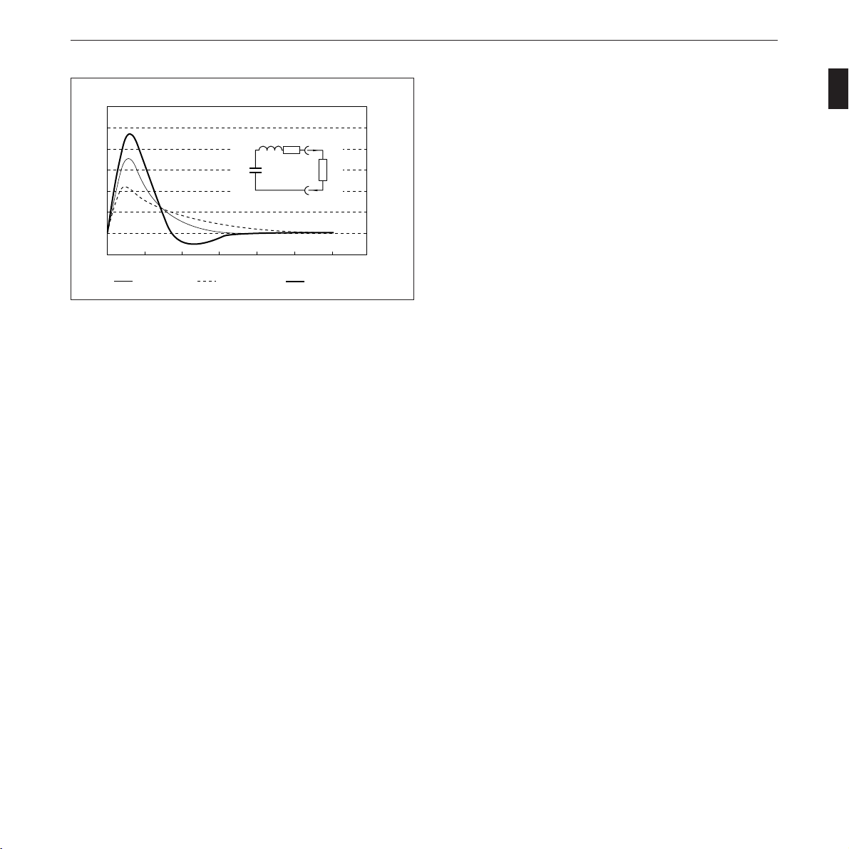
I/A
120
100
80
U
60
40
20
0
-20
0 2 4 6 8 10 12
Ra = 50 Ohm Ra = 100 Ohm Ra = 25 Ohm
c
L = 26 mH
C = 32 μF
R = 6,5 Ω
t
I
R
a
Figure 1-1. CardioServ current-discharge curve (360 J)
14
t/ms
CardioServ comes with three memories whose contents can
be documented individually:
– text memory (code summary documentation)
– event memory (16-s ECG)
– trend memory (trend plots of HR, SpO2, 45 min,
9 hours)
The built-in recorder is initiated automatically or manually.
Extensive safety precautions have been taken to protect the
patient and the user from inadvertent delivery of defibrillation
shocks.
The current-discharge curve corresponds to an approximate
sinusoidal halfwave with aperiodic decay. Figure 1-1 shows
the discharge curve for various external resistances.
227 446 32-I CardioServ V 4.2 7
Page 8
1.2 For your Safety
g
g
g
g
g
Introduction to CardioServ
The safety information given below is divided into the catego-
ries “Danger”, “Warning” and “Caution”.
indicates an imminently hazardous situation
which, if not avoided, will result in death or
Danger
serious injury.
indicates a potentially hazardous situation which,
Warnin
if not avoided, could result in death or serious
injury.
indicates a potentially hazardous situation which,
if not avoided, may result in minor or moderate
Caution
injury and/or damage to the equipment.
provides application tips or other useful information
☞
to assure that you get the most from your equipment.
CardioServ is designed to comply with IEC 60601/
☞
EN60601 requirements. It is Class I equipment and
has an internal power source.
CardioServ operates on line voltages between 95
Warnin
and 240 Volts, 49 to 65 Hz. The mains plug
must be connected to an appropriate power supply
with a non-fused earthed wire. The use of exten-
sion cords is not permitted.
Before putting the device into operation, visually
Warnin
check all connecting cables and electrodes for signs
of damage. Damaged cables and electrodes must
be replaced immediately, before use.
When disconnecting the device from the power
Warnin
line, first remove the plug from the wall outlet.
Disconnect the device from the power line and
Warnin
operate it on battery power, if the integrity of the
protective earth conductor is in doubt.
Set up the device in a location which affords
sufficient ventilation. The ventilation openings of
Caution
the device must not be obstructed. The ambient
conditions specified in the “Technical Specifica-
tions” section must be ensured at all times.
8 CardioServ V 4.2 227 446 32-I
Page 9
Introduction to CardioServ
g
g
g
g
g
g
Warnin
Danger
Warnin
Danger
Warnin
Caution
Devices intended for emergency application must
not be exposed to low temperatures during storage
and transport to avoid moisture condensation at
the application site. Wait until all moisture has
vaporized before using the device. Avoid using the
defibrillator under conditions where prolonged
exposure to or excessive contact with moisture can
occur.
Before putting the defibrillator into operation,
make sure that the paddles and all connection
cables are dry.
CardioServ is an emergency device and must be
ready for operation at any time. For this reason,
the defibrillator battery must always be charged.
This can be achieved by leaving the defibrillator
connected to the power line when it is not needed
in an environment where only battery operation
is possible.
Possible explosion hazard if used in the presence
of concentrated oxygen.
CardioServ is suitable for application in a humid
environment provided the regulations concerning
drip-proof equipment of IEC 60601 are strictly
observed. However, avoid defibrillation in a very
moist or wet environment, unless absolutely
necessary.
Use only the original GEMS IT batteries, as
these are designed for an extended temperature
range.
Magnetic and electrical fields are capable of
Warnin
interfering with the proper performance of the
device. For this reason make sure that all external
devices operated in the vicinity of the defibrillator
comply with the relevant EMC requirements. X-
ray equipment, MRI devices and radio systems
are a possible source of interference as they may
emit higher levels of electromagnetic radiation.
The defibrillator is designed for intracardiac appli-
☞
cation.
Devices may be connected to other devices or to
Warnin
parts of systems only when it has been made
certain that there is no danger to the patient, the
operators, or the environment as a result. In those
instances where there is any element of doubt
concerning the safety of connected devices, the
user must contact the manufacturers concerned or
other informed experts as to whether there is any
possible danger to the patient, the operator, or the
environment as a result of the proposed combina-
tion of devices. Standards IEC 60601-1-1/
EN 60601-1-1 must be complied with in all
cases.
Set up the device so that the operator has a clear,
☞
unobstructed view of the front panel.
Liquids must not be allowed to enter the device.
Warnin
Devices into which liquids have penetrated must
be immediately cleaned and checked by a service
technician.
227 446 32-I CardioServ V 4.2 9
Page 10
Introduction to CardioServ
g
g
g
Danger
Caution
Warnin
Warnin
Caution
Use only the original GEMS IT patient cables.
Do not connect other signal sources to the cables.
Patient signal inputs labelled with the
symbol are protected against damage resulting
from defibrillation and electrocautery voltages.
Nevertheless extreme care must be taken when
devices which are directly connected to the patient
remain applied during electrocautery or defibril-
lation. The distance between ECG electrodes
should be at least 15 cm. If in doubt, disconnect
the patient cable from the device while applying
the defibrillation pulse or performing
electrocautery.
For defibrillation of children use only the special
clip-on electrodes for children listed in section 15
“Order Information and Accessories”.
The full responsibility for the use of accessories
from other manufacturers lies with the user.
Check the device performance at regular intervals
(once a month), strictly following the instructions
given in section 3.2. Do not select high energy
levels for test discharges with defibrillation elec-
trodes shorted together.
At the end of its service life, CardioServ and its
accessories must be disposed of in compliance with
Caution
the special waste control regulations for electronic
parts. If you have any questions in this matter,
please contact GEMS IT GmbH.
Dispose of the packaging material, observing the
Warnin
applicable waste-control regulations and keeping
it out of children’s reach.
Literature
Medical Device Directive
EN 60601-1/1990 + A 1: 1993 + A2: 1995: Medical electrical
equipment. General requirements for safety
EN 60601-1-1/9.1994 + A1 12/1995: General requirements
for safety. Requirements for the safety of medical electrical
systems.
IEC Publication 513/1994: Fundamental aspects of safety
standards for medical equipment.
ROY, O.Z.: Summary of cardiac fibrillation thresholds for
60-Hz currents and voltages applied directly to the heart.
Med. & Biol. Engn. & Computing 18: 657...659 (1980).
For each defibrillation, verify that the selected
and the displayed/charged energy are identical.
Caution
CardioServ also operates on line power when the
☞
battery is depleted or missing.
10 CardioServ V 4.2 227 446 32-I
Page 11
Introduction to CardioServ
g
g
g
g
g
General points to note when handling a defibrillator
Electromedical equipment such as the CardioServ
Warnin
defibrillator must only be handled by persons who
are trained in the use of such equipment and are
capable of applying it properly.
Before using the equipment, the operator must
Warnin
ascertain that it is in correct working order and
operating condition.
The defibrillator paddles must be clean and dry.
Danger
The person carrying out the defibrillation should
☞
have at least one assistant.
The operator must be trained in the use of the
Warnin
defibrillator.
All assistants must be briefed regarding the
Warnin
preparations for and execution of defibrillation.
All tasks must be assigned clearly.
Warnin
Defibrillating a patient with normal heart
rhythm may induce ventricular fibrillation.
Danger
Position the patient flat on a hard, dry surface
where the patient is electrically insulated. The
Caution
patient must not be allowed to come into contact
with metal parts, e.g., bed or litter, in order to
prevent unwanted pathways for the defibrillation
current which endanger the assistants. For the
same reason, do not place the patient on wet
ground (rain, accident in swimming pool).
Have a pacemaker at hand, if possible.
☞
Should cardiac arrest occur or be imminent during
☞
preparations for defibrillation, administer heart
massage and artificial respiration (CPR).
Do not allow the defibrillator paddles to come
into contact with other electrodes or metal parts
Danger
which are in contact with the patient.
Transducers and instruments that are not defi-
brillation-proof must be disconnected from the
Caution
patient.
Interrupt heart massage and artificial respiration
immediately before triggering the shock.
Danger
Immediately before triggering the shock discon-
nect tubes and have assistants step back.
Caution
227 446 32-I CardioServ V 4.2 11
Page 12
Introduction to CardioServ
g
g
g
Caution
Danger
Warnin
Caution
The patient’s chest must be dry, as moisture causes
unwanted pathways for the defibrillation current.
Therefore, when using flammable skin cleansing
agents, wait until they have completely dried.
Possible explosion hazard if used in the presence
of concentrated oxygen, flammable substances
(gasoline) or anesthetic agents. Oxygenation in
the vicinity of the defibrillation paddles must be
strictly avoided; if necessary, interrupt oxygen
supply while defibrillating the patient.
To prevent sparking
– the electrodes should make full contact with
the body
– the electrodes should be pressed firmly onto
the thorax.
Do not deliver shocks into open air. High voltage
may briefly be present at the unprotected paddle
surfaces as a result and endanger the persons
present.
Warnin
Warnin
Defibrillating a patient who has an implanted
pacemaker is likely to impair the pacemaker
function or cause damage to the pacemaker.
Therefore, the following should be observed:
– Select the smallest energy level possible for the
application.
– Do not apply the defibrillation paddles in the
vicinity of the pacemaker electrodes.
– The availability of an external pacemaker is
of utmost importance in this case.
– After the defibrillation the working order of
the implanted pacemaker should be checked
immediately.
Also be aware that children require less energy for
a successful defibrillation than adults. For the
first defibrillation pulse delivered to babies and
toddlers, select an energy level of 2 joules/kg body
weight. For subsequent shocks, increase the energy
up to 4 joules/kg.
When defibrillating children it is especially
important to verify that the paddles make full
Caution
contact with the body surface. This is to be ob-
served also when using the clip-on electrodes for
children (Part No. 303 439 95).
12 CardioServ V 4.2 227 446 32-I
Page 13

Controls and Indicators
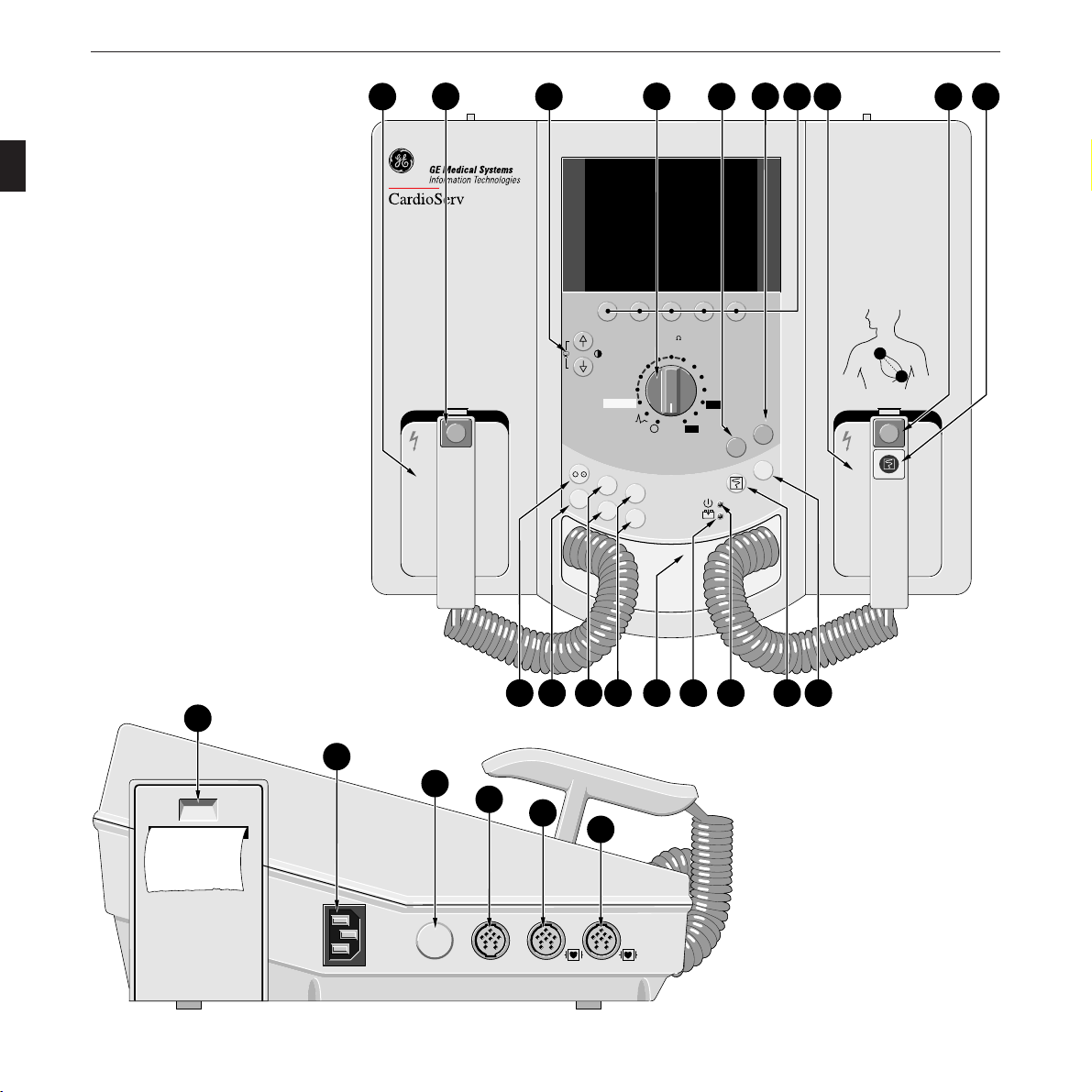
2. Controls and Indicators
This section describes the CardioServ operating controls and
indicators and explains their function.
When operating elements in this manual are identified with
a reference number in parentheses, this number refers to
Figure 2-1 in this section.
You will also find an explanation of all signs and symbols
used on the CardioServ defibrillator.
227 446 32-I CardioServ V 4.2 13
Page 14
Controls and Indicators
-
+
1
2
Shock
3
STERNUM
4
J (50 )
102030
7
5
2
Autosequence
2
P
a
c
e
m
a
k
e
r
S
t
i
m
u
l
a
t
e
+
P/min
+
P/min
mA
–
mA
–
Dem
Fix
50
100
300
360
u
r
6
150
200
Shock
Charge
Shock
Sync
13 8 975
1 Select energy
Apply electrode cream to both paddles
2
Charge defibrillator
Press charge button on apex paddle
(on the device, when using adhesive
or internal electrodes)
Deliver shock3
Press buttons on both paddles simultaneously (on the device, when using
adhesive or internal electrodes)
APEX
Charge
Charge
Shock
3
2
APEX
1418 17 16 15
13
12
11
10
19
20
21
22
23
24
Option
Figure 2-1. Controls and indicators of CardioServ
14 CardioServ V 4.2 227 446 32-I
SpO
EKG
2
Page 15

Controls and Indicators
-
+
1 Defibrillator paddles
Shock
2
button to trigger the defibrillation shock – together
3
with button (8)
3 keys to adjust the LCD contrast. Press both
keys simultaneously to obtain a screen copy.
4 Energy selector, on/off switch
Charge
5
key to charge the unit (manual mode) and to
Shock
trigger the defibrillation shock – together with key (6).
This key assumes the function of button (8) when
internal paddles or adhesive electrodes are used.
Shock
6
key to trigger the defibrillation shock – together
with key (5). This key assumes the function of button
(2) when internal paddles or adhesive electrodes are used.
7 Five selection keys F1 to F5 whose functions change
with the menu displayed. The respective key functions
are indicated by symbols or labels in the bottom line on
the LCD. From the main menu, that appears on power
up, you can access submenus which, in turn, allow the
selection of further options. The back function returns
you to the next higher menu level. The main menu
reappears automatically if you do not depress any of the
keys for about 30 seconds.
8
button to charge the unit (manual mode) and
3
2
Charge
Shock
trigger the defibrillation shock – together with button (2)
11 key to start and stop the recorder. This key assumes
the function of button (9) when internal paddles or
adhesive electrodes are used.
12 Green indicator is lit when the defibrillator operates
on line power.
13 Yellow indicator
is lit when the defibrillator battery
is being charged.
14 Connection for defibrillator paddles
(controls 15 to 18 only on models with pacemaker)
+
mA
15 Keys
16 Keys
17 Pacing mode selection key
mA
+
P/min
to adjust the pacer output
-
P/min
to adjust pacer rate
-
Dem
Fix
(demand/fixed rate)
18 Key to enable and disable the pacemaker
19 Aperture to open the paper compartment
20 Connector for power cord
21 Unassigned
22 1-Volt ECG output
23 Connector for SpO2 sensor
9 button to start and stop the recorder.
Sync
10
key to switch to the synchronized operating mode
24 Connector for patient cable (ECG signal input)
(section 5 “Cardioversion”)
227 446 32-I CardioServ V 4.2 15
Page 16
Controls and Indicators
-
+
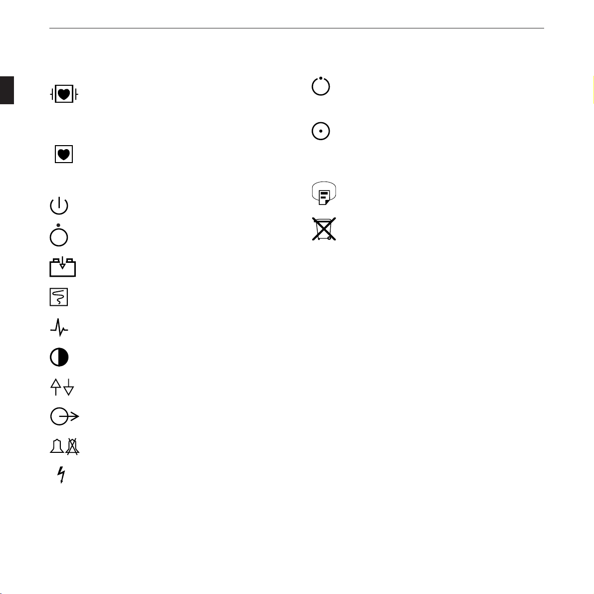
Explanation of the signs and symbols used on the defibrillator
Type CF equipment with highly insulated patient
connections, suitable for intracardiac application,
connections defibrillation-proof.
Type CF equipment with highly insulated patient
connections, suitable for intracardiac application,
connections not defibrillation-proof.
Standby mode (for line-power operation)
Power off
Battery charging
Recorder start
ECG signal
Contrast
Standby or preparatory state only for a part of the
equipment
On, only for a part of the equipment
Hardcopy of screen image
This symbol indicates that the waste of electrical
Refer to Operator’s Manual
and electronic equipment must not be disposed as
unsorted municipal waste and must be collected
separately. Please contact an authorized representa-
tive of the manufacturer for information concern-
ing the decommissioning of your equipment.
Direction indicator
Signal output
Audible alarm on/off
High voltage
16 CardioServ V 4.2 227 446 32-I
Page 17

Setting Up CardioServ and Testing Its Performance
3. Setting Up CardioServ and
Testing Its Performance
In this section you will find information about
– putting CardioServ into operation
– connecting CardioServ to the 12-Volt power supply of
an ambulance vehicle
– customizing the CardioServ settings to suit your per-
sonal requirements
– testing the CardioServ performance before using it on a
patient
227 446 32-I CardioServ V 4.2 17
Page 18
Setting Up CardioServ and Testing Its Performance
3.1 Setting Up CardioServ
The defibrillator is a high-voltage electrotherapy
device and must be handled by qualified person-
Danger
nel only. Improper use of this device can endanger
life. Do not fail to observe the information given
in this manual and only entrust the device to the
hands of trained persons.
Check the electrodes and their leads for signs of
damage every time before you use the defibrilla-
tor. In particular, make a close visual inspection
of the insulation. Replace internal electrodes or
the contact inserts when you detect signs of me-
chanical damage.
CardioServ operates on:
– line power (95 to 240 V, 49 to 65 Hz)
– battery power (rechargeable batteries), i.e., independent
of the power line
– 12-Volt power supplied from the emergency vehicle
(with optional defibrillator mounting system)
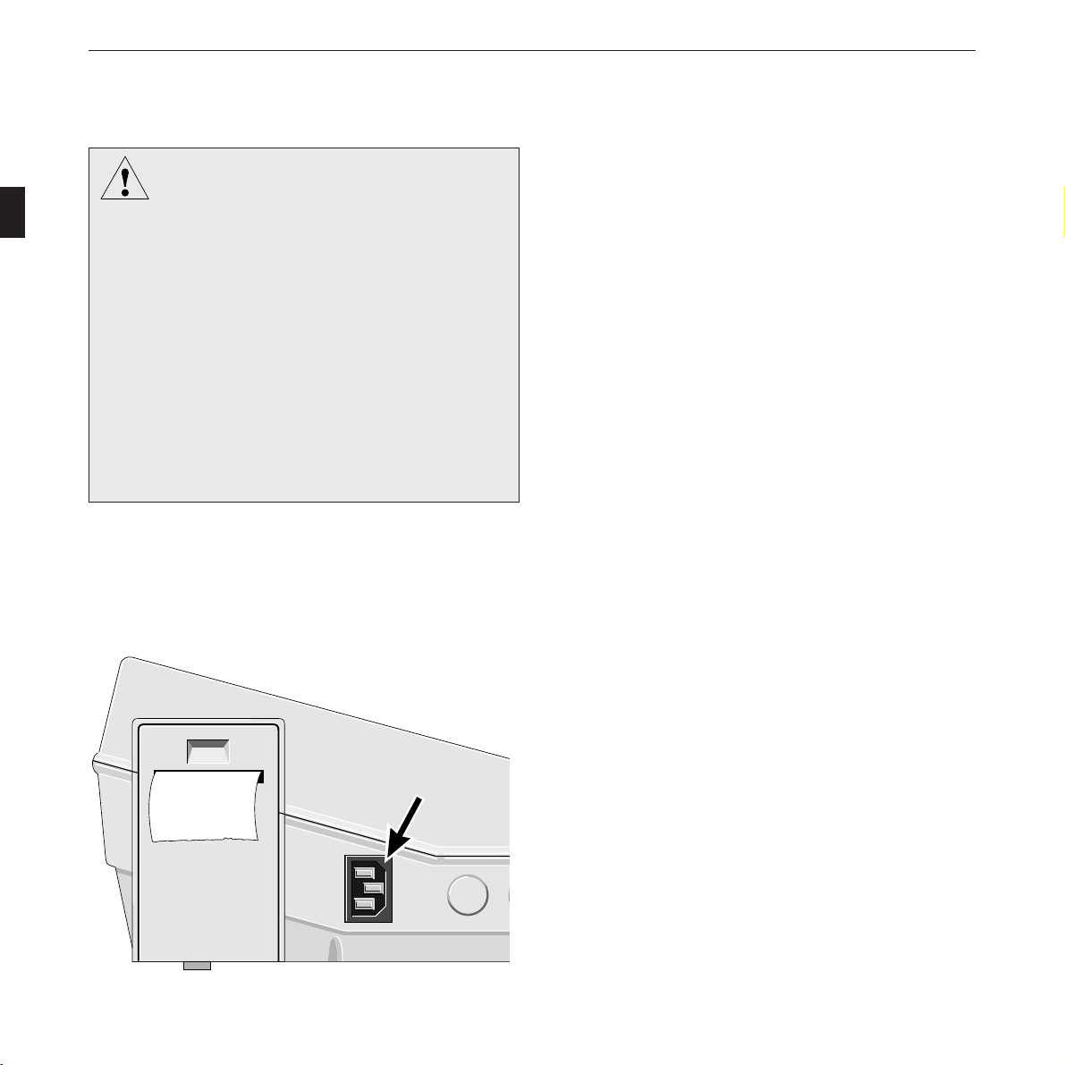
* Use the power cord to connect the defibrillator to the
power line (Figure 3-1).
Figure 3-1. Power input
18 CardioServ V 4.2 227 446 32-I
Page 19
Setting Up CardioServ and Testing Its Performance
360
x
-
+
-
+
Shock
Charge
m
a
k
e
r
S
t
i
m
u
l
a
t
e
u
mA
mA
r
+
+
P/min
m
P/min
Shock
Sync
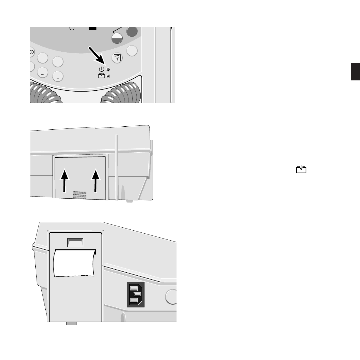
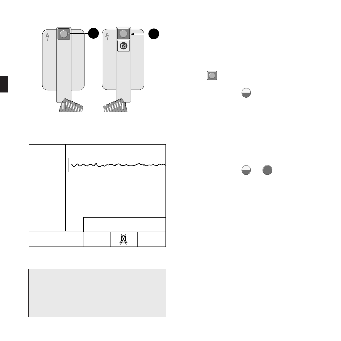
Figure 3-2. Green indicator (indicating that defibrillator is
supplied from the power line)
Figure 3-3. Inserting the battery
* Check that the green indicator is lit (Figure 3-2).
* Check that the battery is in place (Figure 3-3).
Pull back the catch on the underside of the device to remove
the battery. When inserting it, make sure that it clicks prop-
erly into place.
When a battery is inserted, the yellow indicator
starts
flashing as soon as the defibrillator is connected to the power
line (to indicate that the battery is charging). The battery is
fully charged after 16 hours and the indicator is continuously
lit.
* Check that the supply of chart paper is sufficient (Figure
3-4). A stripe marks the last 3 meters of the roll.
Figure 3-4. Recording strip
227 446 32-I CardioServ V 4.2 19
Page 20
Setting Up CardioServ and Testing Its Performance
g
-
+
-
+
-
+
Power Supply From Emergency Vehicles
A qualified technician can be called in to connect the
CardioServ to the 12-Volt supply of an emergency vehicle.
The following points must be noted:
– The negative terminal of the ambulance power supply
system must be connected to the ambulance chassis for
grounding.
– The positive lead of the ambulance power supply system
intended to supply the current must be protected with a
10-A fuse.
T
e
>
s
9
t
5
>
%
8
0
%
<
8
0
%
T
e
S
s
ta
t
rt
– Use only the defibrillator mounting system listed in
section 15 “Order Information and Accessories” or the
external charging unit, if your CardioServ has been
modified accordingly.
Check that the contacts for power supply from the
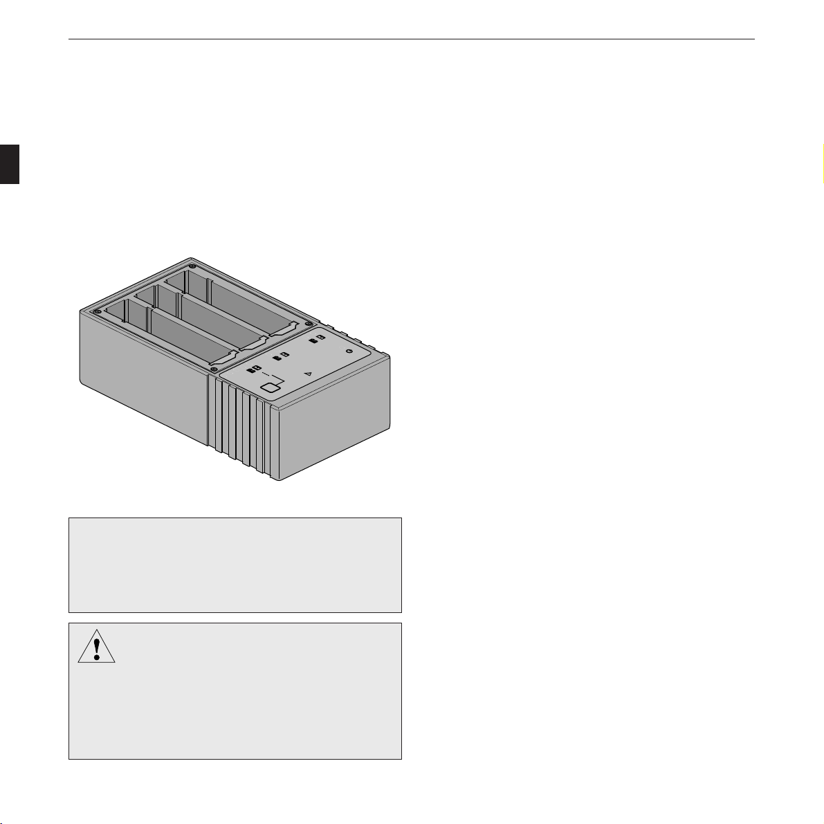
Figure 3-5. Accu Service Unit
defibrillator mounting system on the underside of
CardioServ (next to battery) are clean. Do not damage
We recommend our Accu Service Unit for optimal
☞
them in any way.
care of the batteries. It prolongs the batteries’ service
life and guarantees their operational readiness at all
Important Information on Battery-Power Operation
times.
Rechargeable batteries require special maintenance and con-
A NiCd battery should not be charged while
Warnin
located in direct sunlight, over a radiator, in cold
storage, or in other temperature extremes (not
below 5 °C). When the instrument is charging,
ambient temperatures exceeding 40 °C may
adversely affect battery capacity and life.
20 CardioServ V 4.2 227 446 32-I
tinued checks to assure they function in emergency situations.
It is normal for batteries of this type to selfdischarge when not
in use.
The battery charges automatically when CardioServ is con-
nected to the power line (yellow indicator (13) flashes).
Page 21
Setting Up CardioServ and Testing Its Performance
In order to ensure its functioning as an emergency device, the
defibrillator should not be disconnected from the power line
for more than 48 hours.
A fully charged battery supplies power for 35 defibrillation
shocks of 360 joules or 2 hours of monitoring (or 1.2 hours of
monitoring if the CardioServ unit has pacemaker and SpO
option). It takes 16 hours to charge a depleted battery.
Proceed as follows to test the battery charge level:
☞
– Disconnect CardioServ from the power line.
– Trigger a test discharge of 360 joules (see
section 3.2 “Testing the Defibrillator Perform-
ance”).
– If you are not prompted to charge the battery,
the charge level should be sufficient for at least
5 more 360-joule shocks.
Monthly battery maintenance and checks:
☞
1. Disconnect CardioServ from the power line and
discharge fully charged battery in the monitoring
mode. To do so, set energy selector switch to ,
(SpO2 sensor not connected) and wait until device
switches off.
2
Inserting CardioServ In Its Softcase
* Open both zips on the CardioServ softcase.
* Undo the two Velcro strips on the front of the softcase.
* Open the Velcro flap located in front of the CardioServ
printer.
* Place the softcase on the small base, so that the softcase is
positioned as though you were carrying it.
* Disconnect the paddles on the CardioServ and remove
them.
* Hold all the opened up parts of the softcase to the side
and put the CardioServ into the softcase.
* Pull the softcase by the two Velcro strips on the black
base into position, ensuring that the feet of the
CardioServ are in the cut-out openings provided.
* Close the two front Velcro strips as well as the flap in
front of the printer at the side.
2. Check how long it takes before battery is depleted.
If the time is less than 1.8 hours, the battery is too
old or improperly maintained and must be
replaced.
3. Recharge the battery. This will take 16 hours.
For easy, convenient care and maintenance of the
batteries, use our “Accu Service Unit”.
227 446 32-I CardioServ V 4.2 21
* Close the zips.
* If the individual cut-out openings for the external con-
nections, paddles or feet are not correctly positioned,
pull the material at this point into the right shape.
* Reconnect the paddles and put them back into the
CardioServ recesses.
Page 22

Customizing the defibrillator settings
Setting Up CardioServ and Testing Its Performance
Further steps that can be taken while setting up the defibrilla-
tor include customizing the device functions. This allows you
to select defibrillator default settings which suit your personal
preferences. CardioServ saves these configured settings and
reactivates them automatically every time you switch the
Refer to section 11 “The Defaults Menu” for a detailed
explanation of how to customize the CardioServ, including
the language selection (available languages are English,
French, German, Italian, Portuguese, Russian, Spanish and
Swedish).
defibrillator on. The following chart shows the factory settings
of all parameters and the optional adjustments.
retemaraP noitpircseD gnitteSyrotcaF egnartnemtsujdA sgnittesdezimotsuC
stimiLRH stimilmralaRH 061/04 ffo003ot51ffo
ytivitisneS ezislangisGCE 1 Vm/mc2,1,5.
daeL 1 selddap+sdaeldradnatslla
.qesotuA slevelygrenegnicneuqesotua J063,J002,J002 ,J063,J003,J002,J051
OpS
stimiL stimilmrala ffo/09 ffo001ot51ffo
2
kcoL-C OpSdezinorhcnys-GCE
OpS
2
resU )sretcarahc04(emanrotxeteerf
emiT.tnI OpS
mralAliaFdaeL ffo s03/ffo
peeBSRQ ffo ffo/no
enoTmralA ffo ffo/no
tuotnirPmralA tratsredrocer.motua ffo ffo/no
tuotnirPkcohS tratsredrocer.motua no ffo/no
tuotnirP.tnoC tratslaunamnopupotsredrocer ffo ffo/no
rekamecaP etareslup MPB06 nim/P051ot51
yalpsiD lamron desrever/lamron
yalpsiD seerged0 seerged081/seerged0
emuloV slangisoiduallafoemulov duol wol/duol
retliFCA zH05 ffo/zH06/zH05
retliFelcsuM tcafitranoitomfonoitanimile no ffo/no
emiT/etaD
tamroFetaD YYYY:MM:DD YYYY:DD:MM/YYYY:MM:DD
egaugnaL namreG ,namreG,hcnerF,hsilgnE
tluafedyrotcaF sgnittesyrotcafhsilbatseer ffo ffo/no
2
2
emitnoitargetni s8 )dednemmocerton(s21,s8,s4
tnemerusaem ffo ffo/no
,naissuR,eseugutroP,nailatI
hsidewS,hsinapS
Table 1
22 CardioServ V 4.2 227 446 32-I
Page 23
Setting Up CardioServ and Testing Its Performance
m
J (50 Ω)
20
10
7
5
2
Autosequence
P
a
c
e
m
a
k
e
r
S
t
i
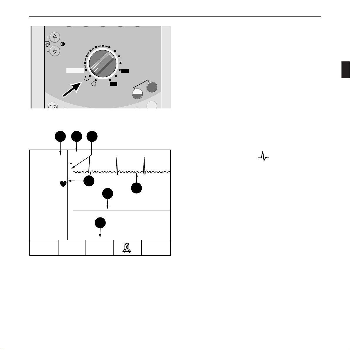
Figure 3-6. Switching on CardioServ
a b
Paddle
c
0
160 BPM
140 ECG
HR Alarm
d
3.2 Testing the Defibrillator
30
50
100
150
200
300
360
Charge
Shock
Shock
Sync
e
f
Performance
On power up CardioServ runs an automatic selftest. Any
malfunctions identified during this test result in an error
message displayed on the LCD (refer to section 12 “Error
Indications and Messages”). As a further performance test a
trial defibrillation can be triggered.
The energy selector is used to switch CardioServ on and off.
Once you have become familiar with CardioServ you can thus
switch on the defibrillator and select the required energy in
one single operation.
* Set the energy selector to the position. No energy
will be stored in this position of the switch.
The defibrillator beeps and displays a checkered pattern
(LCD performance test). Next the main display appears
(Figure 3-7).
g
The “Paddle” message (b, Figure 3-7) indicates that no pa-
tient cable is connected and that the ECG signal is acquired
via the defib paddles. Upon connection of the patient cable
FreezeSpO2ECG
Next
Menu
the selected ECG lead is displayed here. CardioServ is now
ready for operation.
Figure 3-7. CardioServ main display
a heart/pulse-rate reading with alarm limits
b ECG signal source
c 1-mV calibration pulse
d alarm message, QRS blip
e signal trace, channel 1
f signal trace, channel 2
g menu
227 446 32-I CardioServ V 4.2 23
Page 24
Setting Up CardioServ and Testing Its Performance
Do not trigger more than 5 consecutive test
discharges (or internal safety discharges) within
Caution
15 minutes at max. energy setting.
Paddle
0
160 BPM
140 ECG
HR Alarm
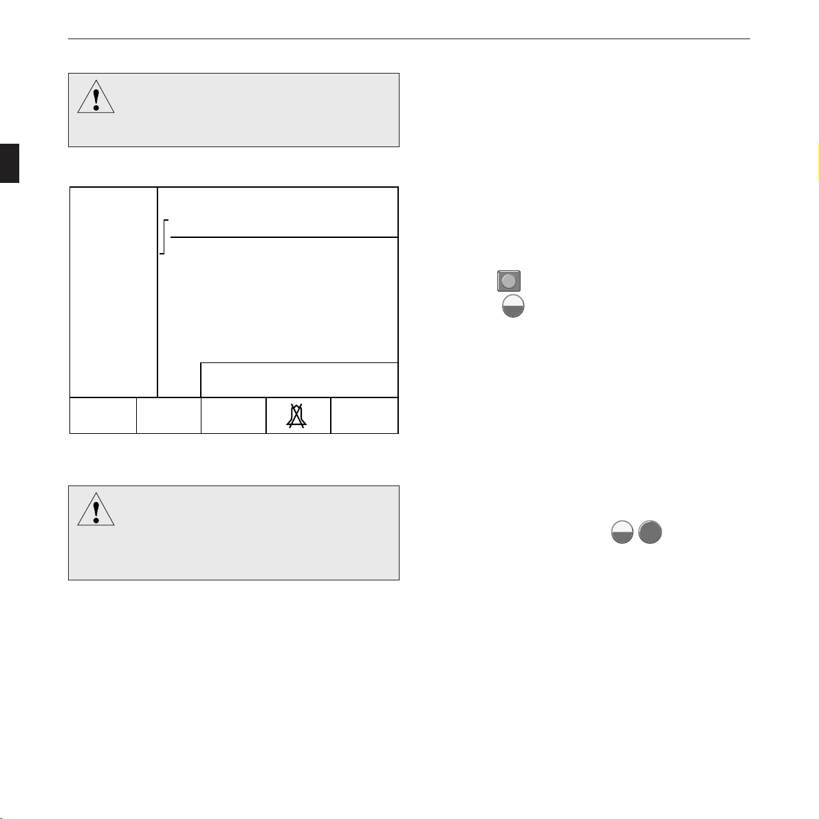
Figure 3-8. Display of selected energy
360 J
Next
MenuFreezeSpO2ECG
Test Discharge
A test discharge can be triggered to check the defibrillator
discharge circuit. For this test the stored energy is discharged
into the device via two contacts in the paddle compartments.
* Set the energy selector to 360 joules (50 joules, if inter-
nal electrodes are connected). The display first shows the
selected energy (Figure 3-8).
2
Charge
* Press the
(Press the
Shock
button on the paddle to charge the unit.
3
Charge
key on the defibrillator, when using
Shock
internal electrodes.)
You may now watch the defibrillator charging.
* When the selected energy level has been reached,
CardioServ beeps and the stored energy is displayed
(Figure 3-9).
Do not deliver shocks into open air. High voltage
may briefly be present at the unprotected paddle
Caution
surfaces as a result and endanger the persons
onds. To do so, simultaneously press the buttons on
Charge
both paddles (or press the two
Shock
Shock
keys on the
defibrillator, when using internal electrodes).
present.
If more than 5% of the available energy are lost before the
defibrillation pulse is triggered, CardioServ recharges until the
required energy level is reached.
24 CardioServ V 4.2 227 446 32-I
* Trigger the defibrillation pulse within the next 30 sec-
Page 25
Setting Up CardioServ and Testing Its Performance
Paddle
0
160 BPM
140 ECG
HR Alarm
Energy
available
Figure 3-9. Display of available energy
If you do not trigger the defibrillation pulse within
☞
30 seconds, an internal safety discharge is initiated
automatically.
360 J
Next
MenuFreezeSpO2ECG
After defibrillation, the beeping sound stops, and the energy
actually delivered into a 50-ohm resistance is displayed for
10 seconds in place of the stored energy (Figure 3-9). The
delivered energy must not deviate more than ±15% or
±4 joules (whichever is greater) from the selected value. A
recording is initiated at the same time (16-second strip).
Should the discharge circuit be interrupted (paddles not
properly placed on contacts in the compartments, defective
lead), an internal safety discharge is initiated 200 ms after the
defibrillation shock has been triggered. In this case the “deliv-
ered energy” is “0”.
If the defibrillator cannot store the selected energy so that
selected and stored energy values differ, the LCD shows the
message “Energy high” or “Energy low”. The defibrillation
pulse can be triggeed all the same.
* Switch off CardioServ (set energy selector to ).
The message “Energy high” or “Energy low”
indicates that CardioServ needs to be repaired.
Caution
If, in spite of this energy storage problem, the
device has to be employed, it will display the
message “Self-test failed. Charge Energy Error”
Testing the Pacemaker Performance
The performance of the pacemaker can be tested with a
commercially available pacemaker tester (e.g. CS300 Simula-
tor from GEMS IT, part no. 417 983-001).
upon power up. In this situation press one of the
function keys and proceed as usual.
Performance Test
Caution
Test the defibrillator performance once a week:
test 1 – defibrillator connected to mains, battery
removed,
test 2 – defibrillator disconnected from mains,
battery inserted
227 446 32-I CardioServ V 4.2 25
Page 26

For your notes
Setting Up CardioServ and Testing Its Performance
26 CardioServ V 4.2 227 446 32-I
Page 27

Non-Synchronized Defibrillation
4. Non-Synchronized Defibrillation
This section describes first how to perform a non-synchro-
nized defibrillation, using the standard defibrillation
paddles. The subsequent explanations refer to the use of
internal and disposable adhesive electrodes.
At the end of this section you will find a summary of all
necessary operating steps (brief operating instructions).
227 446 32-I CardioServ V 4.2 27
Page 28
Non-Synchronized Defibrillation
g
4.1 Defibrillation with Standard
Electrodes
The information given in section 1.2 must be
Warnin
observed without fail to ensure safe and reliable
application of the device.
Always switch off CardioServ before exchanging
the defibrillation paddles.
Danger
Paddle
0
160 BPM
140 ECG
HR Alarm
200 J
SpO2ECG
Figure 4-1. Main display, indication of ECG lead, manual
operation and selected energy
Next
MenuFreeze
The energy selector can be set to the autosequence position,
where the defibrillator automatically sequences the preset
energy levels. The preset factory default setting is the sequence
recommended by AHA/ERC (200 J, 200 J, 360 J). The
factory default values can be changed from the defaults menu.
You can choose among 150 J, 200 J, 300 J and 360 J.
* Set the energy selector (4) to “Autosequence” or to the
required energy value (this turns on CardioServ).
The defibrillator beeps and displays a checkered pattern (LCD
performance test). Next the main display appears (Figure
4-1). When a patient cable is connected the selected ECG
lead is displayed (selectable).
* Check that the energy selector locks in on the correct
position and that the display shows the selected energy
(Figure 4-1).
The energy depends on the defibrillation mode, on the
patient’s age and constitution. In external application the
thickness of the tissue is also a factor which influences the
amount of energy required.
The energy necessary for successful ventricular defibrillation
without damaging the myocardium has for many years been a
matter of scientific controversy. The manufacturer is therefore
not able to give any recommendations.
28 CardioServ V 4.2 227 446 32-I
Page 29
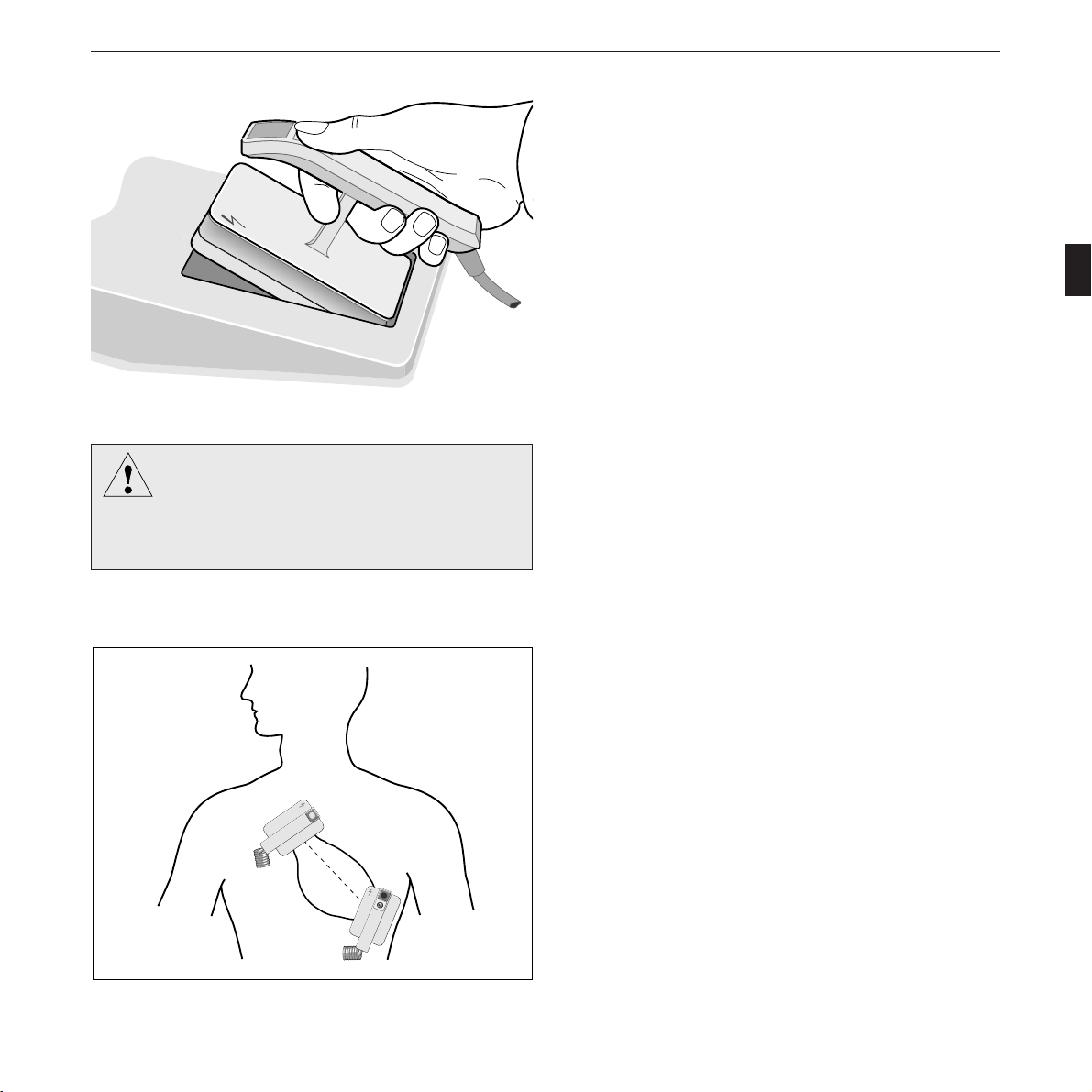
Figure 4-2. Removing the paddles
g
Do not apply the paddles over
Warnin
– sternum or clavicle
– nipples
– implanted pacemaker or defibrillator.
Non-Synchronized Defibrillation
In emergency situations AHA recommends for adult patients
1. defibrillation with 200 joules; if unsuccessful, repeat
2. defibrillation with 200 joules; if unsuccessful, repeat
3. defibrillation with max. energy setting (360 joules).
Please note that children require less energy for successful
ventricular defibrillation than adults. For the first defibrilla-
tion pulse delivered to babies and small children, select an
energy level of 2 joules/kg body weight. For subsequent
shocks, the energy may be increased to 4 joules/kg.
In compliance with IEC requirements the energy adjusted on
this defibrillator is not the stored energy, but the energy
released into an external resistance of 50 ohms (patient resist-
ance + electrode-to-skin contact resistance). The energy
selector is labelled accordingly.
* Remove the paddles from their compartments (as shown
in Figure 4-2). Carefully dry the electrodes, if they are
wet. The handles, in particular, must be completely dry.
Apply an ample amount of electrode cream to each
paddle.
3
STERNUM
* Apply the electrodes to the patient’s thorax so that the
greatest possible amount of energy flows through the
myocardium (the imaginary connecting line between the
2
Charge
3
APEX
two electrode centers should be identical with the cardiac
median line; Figure 4-3).
* Press paddles firmly down onto the patient’s thorax..
Figure 4-3. Paddle application points
227 446 32-I CardioServ V 4.2 29
Page 30
Non-Synchronized Defibrillation
2
Charge
Shock
3
STERNUM
2
3
Charge
Shock
8
APEX
Figure 4-4. Buttons to initiate energy storage and to trigger the
defibrillation shock
Paddle
0
160 BPM
140 ECG
HR Alarm
The ECG signal trace appears on the monitor.
* Do not touch the patient any more and warn all those
present.
2
Charge
* Press the
Shock
button (8) on the apex paddle to initiate
3
charging (Figure 4-4). When using internal electrodes or
defibrillation pads, press
Charge
on the device.
Shock
When the selected energy level has been reached (message
“Energy available”), CardioServ beeps and the stored energy is
displayed (Figure 4-5).
* Trigger the defibrillation shock within the next 30 sec-
onds by simultaneously pressing the buttons on both
paddles (Figure 4-4). When using internal electrodes or
defibrillation pads, press
Charge
Shock
and
Shock
on the device.
If more than 5% of the available energy are lost before the
defibrillation shock is triggered, CardioServ recharges until
the required energy level is reached.
Energy
available
FreezeSpO2ECG
200 J
Next
Menu
Figure 4-5. Display of available energy
☞
When the defibrillator is already charged you can
increase the energy level simply by turning the energy
selector to the new setting. To decrease the energy
level, set the selector to the lower value and initiate
charging again.
30 CardioServ V 4.2 227 446 32-I
Page 31

Non-Synchronized Defibrillation
g
Paddle
0
160 BPM
140 ECG
HR Alarm
Energy
delivered
Figure 4-6. Display of delivered energy
The “Check Electrode” message refers to the defibril-
☞
lation paddles only when no patient cable is con-
nected. It refers to the ECG electrodes when the
patient cable is plugged in.
If you do not trigger the defibrillation pulse within
☞
30 seconds, an internal safety discharge is initiated
automatically. You will then have to recharge the
defibrillator.
The defibrillation energy (high voltage!) remains
Warnin
applied to the defibrillation paddles until fully
discharged. Do not touch the paddle surface! The
internal safety discharge is completed when the
selected energy is displayed again.
198 J
Next
MenuFreezeSpO2ECG
– After defibrillation, the beeping sound stops, and the
energy actually delivered is displayed for 10 seconds in
place of the stored energy (Figure 4-6). At the same time
the recorder writes a 16-second ECG (including a his-
tory of 4 seconds) (adjustable, Figure 4-7). CardioServ
saves this recording (4 s history, 5 s blanked, 10 s after
release of shock), and it can be printed off again at any
time. Also refer to section 7 “The Memories of
CardioServ”.
– When the electrodes are not applied at all or they are not
properly applied to the skin, the message “Check Elec-
trode” is displayed. The defibrillation shock can be
triggered all the same. Nevertheless it is recommended to
reduce skin impedance (risk of skin burns!), for instance,
by applying more electrode cream to the paddles or by
pressing them down firmly.
– When there is a break in the discharge circuit (paddles
not properly applied, leads or paddles defective), an
internal safety discharge is initiated 200 ms after the
defibrillation shock has been triggered. In this case the
“delivered energy” is “0”.
_ If the defibrillator cannot store the selected energy so
that selected and stored energy values differ, the LCD
displays a warning. The defibrillation pulse can be
triggered anyway (notify service).
* Once therapy has ended, set the selector switch to
for monitoring of the patient’s ECG.
227 446 32-I CardioServ V 4.2 31
Page 32

Non-Synchronized Defibrillation
a
DEFIB 09. 07 .1997 09 : 16 : 12 50 Hz 35 Hz 360 JOULES HR : O BPM
SHOCK
PADDLE
1 CM/MV
25 MM/S ST. JOHN’S 97
g
h
i
b
k
c
<5s>
ed
Figure 4-7. Example of a recording initiated by a defibrillation pulse
a initiation e delivered energy i paper speed
b date f heart rate k name of hospital/practise
c time g ECG lead
d active filters h sensitivity
f
PATIENT
DATE OF BIRTH.............
USER........................
COMMENTS.................
SELECTED ENERGY.........
DELIVERED ENERGY........
ALARM LIMIT HR...........
ALARM LIMIT SPO2 .......
PACEMAKER................
DATE/TIME
* After use, switch off CardioServ (set selector switch to
).
* Clean the paddles and the device as described in section
13.
* After cleaning, return the paddles to their compartments
as shown in Figure 4-8.
Figure 4-8. Returning the paddles to their compartments
32 CardioServ V 4.2 227 446 32-I
Page 33

Non-Synchronized Defibrillation
i
i
4.2 Defibrillation with Internal
Electrodes or Single-Use Pads
Internal Electrodes
When using CardioServ with internal or adhesive
☞
electrodes, charging is initiated with
Charge
Shock
and defi-
brillation is triggered by simultaneously pressing the
Charge
Shock
and
Shock
(Figure 4-9). Only sterile electrodes
may be used for internal defibrillation!
J (50 Ω)
20
utosequence
S
t
i
m
u
n
n
mA
10
7
5
2
l
a
t
e
u
r
+
30
360
50
300
100
200
150
Charge
Shock
Shock
Sync
Figure 4-9. Panel keys to initiate charging and to trigger the
defibrillation shock
When electrodes for internal defibrillation are connected to
CardioServ, it is not posssible to store energy above 50 joules.
If you set the selector to values higher than 50 joules, release
of the defibrillation pulse is blocked for reasons of patient
safety (“Energy high” will be displayed!). Simply turn the dial
back and initiate charging again, this time selecting not more
than 50 joules.
Spoon-shaped electrodes are used for internal defibrillation.
Their contact surface must match the dimensions of the heart,
as the spoons should make full contact with the tissue.
You can choose from 3 different spoon sizes (section 15
“Order Information, Accessories”). As the spoons are in direct
contact with the heart – hence the term “direct defibrillation”
– energy levels considerably lower than those for transthoracic
(external) defibrillation are sufficient.
Please note that internal electrodes must be sterilized before
use (section 13 “Cleaning and Disinfection”).
227 446 32-I CardioServ V 4.2 33
Page 34

Non-Synchronized Defibrillation
STERNUM
electrode + connector
electrode + connector
Figure 4-10. Anterior – anterior placement
front back
APEX
Single-Use Defibrillation Pads
* Use pads before their expiration date.
* A pair of defibrillation pads may remain attached to
the patient for up to 24 hours. They withstand up to
50 shocks of 360 joules each.
* Apply the pads (part no. 919 202 94 adult pads, part no.
919 202 95 pediatric pads) as shown in Figure 4-10 for
an anterior-anterior placement, and as shown in Figure
4-11 for an anterior-posterior placement:
– Shave any hair from each site. This improves conduc-
tivity and makes removal of the pad easier.
– Place the pads on the patient so that the connectors
point to either side of the patient. In this position the
connecting cables will not hinder CPR measures.
– The electrodes are pregelled; therefore do not use
APEX STERNUM
additional contact cream or paste.
Figure 4-11. Anterior – posterior placement
– Do not use pads, if the gel has dried out.
– Peel off the backing from each pad and place the pad
carefully on the appropriate site.
34 CardioServ V 4.2 227 446 32-I
Page 35

223 383 01
g
g
Non-Synchronized Defibrillation
* Then press the connector of cable 223 383 01 on to the
electrode contact pin until you hear it click into place.
Observe the connector lables: “A” = apex, “S” = sternum.
A
Figure 4-12. Connecting the cables
223 346 01
919 202 94
919 202 95 (K)
919 201 89
919 202 75 (K)
The round adhesive electrodes (part no. 919 201 89) can be
used with adapter lead 223 346 01. When connecting the
electrode to the lead, take care that they engage properly. To
disconnect them, simply press on the rear part of the catch
(Figure 4-13).
* Before defibrillating the patient, verify the position and
adhesion of the pads.
* Defibrillate the patient as described in section “Defibril-
lation with Standard Electrodes”. Note, however, that
energy storage and defibrillation pulse will have to be
triggered with the panel keys.
* After use, carefully peel off the electrodes from the
patient’s skin (Figure 4-14) and discard them immedi-
ately.
Figure 4-13. Connecting the defib pads to the adapter cable
When monitoring the patient with the adhesive
defib pads, make sure that the energy selector is in
the monitoring position .
incorrect
correct
Warnin
Discard disposable defibrillation pads immedi-
Warnin
ately after use. Do no reuse them!
Figure 4-14. Removing defibrillation pads
227 446 32-I CardioServ V 4.2 35
Page 36

Non-Synchronized Defibrillation
4.3 Brief Operating Instructions (non-synchronized)
External Electrodes/Paddles
* Set energy selector to “Autosequence” or select
the required energy
* Remove paddles from compartments and apply
electrode cream
* Apply electrodes to thorax
2
Charge
* Initiate defibrillator charging
Shock
3
* Wait for beep to sound and for stored energy to
be displayed
* Warn bystanders, do not touch the patient any
more and trigger shock; to do this, simultane-
2
Charge
Shock
ously press
Shock
on both paddles
3
3
* Watch ECG, repeat defibrillation if necessary or
set energy selector to , if defibrillation was
successful
* Switch off CardioServ after use (set energy
selector to )
* Clean paddles and defibrillator
Internal Electrodes or Pads
* Connect internal electrodes or pads to
1
CardioServ
* Apply pads
* Set energy selector to “Autosequence” or select
the required energy (50 joules max. for internal
1
defibrillation)
2
* Initiate defibrillator charging
* Wait for beep to sound and for stored energy to
be displayed
3
* Warn bystanders, do not touch the patient any
more and trigger shock; to do this, simultane-
Charge
ously press the
Shock
Shock
* Watch ECG, repeat defibrillation if necessary or
set energy selector to , if defibrillation was
successful
* Switch off CardioServ after use (set energy
selector to )
* Dispose of single-use electrodes, clean defibrilla-
tor
Charge
Shock
keys on the panel
2
3
* Clean/sterilize internal electrodes
36 CardioServ V 4.2 227 446 32-I
Page 37

Cardioversion (Synchronized Defibrillation)
5. Cardioversion
(Synchronized Defibrillation)
This section describes first how to perform a synchronized
defibrillation (cardioversion). For this purpose, the ECG is
picked up either via the paddles or via separate ECG elec-
trodes.
At the end of this section you will find a summary of all
necessary operating steps (brief operating instructions).
227 446 32-I CardioServ V 4.2 37
Page 38

Cardioversion (Synchronized Defibrillation)
g
g
5.1 General Information
The information given in section 1.2 must be
Warnin
observed without fail to ensure safe and reliable
application of the device. Also read section 6.1
“Displaying the ECG”.
False Triggering – If ventricular fibrillation
Warnin
occurs during the intervention, you must switch to
the non-synchronized mode to be able to trigger a
defibrillation pulse, because it is not possible to
detect a QRS complex in the presence of ventricu-
lar fibrillation and the QRS complex is necessary
to derive the trigger pulse.
Do not use a pacemaker ECG for triggering,
because the trigger pulses derived from pacemaker
ECGs may be incorrect and synchronized delivery
of the defibrillation shock may not be possible.
Following each synchronized defibrillation,
☞
CardioServ reverts to the non-synchronized mode.
Please note that the synchronized mode must be
deliberately activated with
Sync
every time you
want to perform cardioversion. This measure is to
ensure that in emergencies the defibrillator is always
ready to deliver nonsynchronized shocks.
For cardioversion, the defibrillation shock is delivered in
synchronization with the heart action (on the R-wave), as the
heart is still working. As a prerequisite the patient’s ECG
signal must be supplied to the defibrillator. After the defibril-
lator has received the “defibrillation command” from the
operator who pressed the appropriate keys, the defibrillator
will wait for the next R-wave to derive the trigger signal.
It is strongly recommended to acquire the ECG via separate
ECG electrodes. However, you may also use adhesive defibril-
lation pads and simultaneously acquire the ECG via these
pads.
38 CardioServ V 4.2 227 446 32-I
Page 39

Cardioversion (Synchronized Defibrillation)
5.2 Performing Cardioversion
red
R L
white
black
N F
C
Figure 5-1. ECG electrode placement
yellow
green
ECG Acquisition via ECG Electrodes and Patient Cable
Use only siver/silver chloride electrodes if you intend to
acquire the ECG signal via the patient cable. This type of
electrodes prevents polarization voltages which may be caused
by the defibrillation shock, resulting in an ECG trace simulat-
ing cardiac arrest.
* Apply the electrodes as shown in Figure 5-1 and connect
them to CardioServ via the patient cable (Figure 5-2).
For further information on ECG signal acquisition, please
refer to our application note on electrocardiography and to
the relevant literature.
ECG Acquisition via Defibrillation Pads
* Apply the pads as described in section 4.2.
* Check that no patient cable is connected to ECG signal
input (Figure 5-2).
Option
SpO
EKG
2
The ECG will now be acquired via the defibrillation pads.
Perform cardioversion as described below.
Figure 5-2. ECG signal input
227 446 32-I CardioServ V 4.2 39
Page 40

Cardioversion (Synchronized Defibrillation)
2
-
+
100
150
200
300
360
u
r
Charge
Shock
3
Shock
Sync
Figure 5-3. Key to select synchronized defibrillation
3
APEX
Charge
Shock
Cardioversion
* Set the energy selector to (this turns on
CardioServ) and check the ECG trace.
The defibrillator beeps and displays a checkered pattern (LCD
performance test). Next the main display and the label of the
selected lead are shown (when patient cable is connected).
CardioServ is now ready for operation.
The defibrillator selects the following settings:
APEX
– lead I (selectable)
– AC line filter on (selectable)
– sensitivity of 1 mV/cm (selectable)
If you wish to select another lead or sensitivity, proceed as
follows (these are only temporary changes which will not be
saved):
* Press the
* Use the
ECG
softkey to call up the ECG submenu.
I...III
aV...V
softkey to select a suitable ECG lead
Paddle
(shown at a, Figure 5-4).
* Use the
* Press
1
cm/mV
Sync
(Figure 5-3).
softkey to select the sensitivity.
The “Sync” mode is indicated on the LCD (c, Figure 5-4).
40 CardioServ V 4.2 227 446 32-I
Page 41

Cardioversion (Synchronized Defibrillation)
a
b
II
62
160 BPM
140 ECG
d
Figure 5-4. Screen display
a selected lead
b Sync mark
c Sync mode on
d heart symbol
On the recording strip each sync pulse is identified
☞
with a dash above and below the ECG trace.
If no SYNC marks are displayed, do not trigger a
defibrillation shock, because the shock might be
Danger
delivered unsynchronized with the QRS complexes.
Next
MenuFreezeSpO2ECG
c
Sync
Verify that the heart symbol flashes regularly on the LCD and
that the sync mark appears at regular intervals along the upper
LCD margin (b, Figure 5-4). Otherwise select another lead
using softkey
It is important that the ECG exhibit the following characteris-
tics
– the R-wave amplitude should be greater than 0.5 mV,
1 mV or more are recommended
– the T-wave amplitude should be small in relation to the
R-wave amplitude
– the SYNC mark should be located above the leading
edge or peak of the R-wave
When the synchronized defibrillation mode is selected, each
QRS complex is identified with a SYNC mark (b, Figure
5-4). If these SYNC marks are missing, synchronized defibril-
lation will not be possible. Reasons for missing SYNC marks
include poor ECG signal quality. Select another ECG lead,
check electrode contact or disable and re-enable the SYNC
mode.
For an accurate estimation of the phase in which the defibril-
lation shock will occur, you can mark the latest point in time
on the printed ECG: the defibrillation shock will be triggered
not later than 60 ms after the SYNC mark.
I...III
aV...V
of the ECG submenu.
Paddle
* Remove the paddles from their compartments. Carefully
dry the electrodes, if they are wet. The handles, in
particular, must be completely dry. Apply an ample
amount of electrode cream to each paddle.
* Set the energy selector to the required energy level
(“Autosequence” is not suitable for cardioversion).
227 446 32-I CardioServ V 4.2 41
Page 42

Caution
STERNUM
g
Cardioversion (Synchronized Defibrillation)
The energy depends on the defibrillation mode, on the pa-
tient’s age and constitution. In external application the thick-
ness of the tissue is also a factor which influences the amount
of energy required.
The energy necessary for successful ventricular defibrillation
3
without damaging the myocardium has for many years been a
matter of scientific controversy. The manufacturer is therefore
not able to give any recommendations.
2
Charge
3
APEX
Figure 5-5. Paddle placement
Do not apply the paddles over
Warnin
– sternum or clavicle
– nipples
– implanted pacemaker or defibrillator.
2
Charge
Shock
3
STERNUM
2
3
Charge
Shock
8
APEX
Figure 5-6. Buttons to inititate energy storage and to trigger the
defibrillation shock
The American Heart Asociation AHA recom-
mends the following energy levels for cardio-
version: 50 J, 100 J, 200 J, 300 j, 360 J.
* Apply the electrodes to the patient’s thorax so that the
greatest possible amount of energy flows through the
myocardium (the imaginary connecting line between the
two electrode centers should be identical with the cardiac
median line; Figure 5-5).
* Press paddles firmly down onto the patient’s thorax.
* Do not touch the patient any more and warn all those
present.
2
Charge
* Press the
Shock
button (8) on the apex paddle to initiate
3
charging (Figure 5-6). When using defibrillation pads,
press the
Charge
key on the CardioServ control panel.
Shock
When the selected energy level has been reached, CardioServ
beeps and the stored energy is displayed (Figure 5-7). It
should be identical with the selected value (±15% or
±4 joules, whichever is greater)
42 CardioServ V 4.2 227 446 32-I
Page 43

Cardioversion (Synchronized Defibrillation)
Shock
g
II
62
160 BPM
140 ECG
Energy
available
Figure 5-7. Display of the stored energy
The “Check Electrode” message refers to the defibril-
☞
lation paddles only when no patient cable is con-
nected. It refers to ECG electrodes when the patient
cable is plugged in.
The defibrillation energy (high voltage!) remains
Warnin
applied to the defibrillation paddles until fully
discharged. Do not touch the paddle surface! The
internal safety discharge is completed when the
selected energy is displayed again.
100 J
Next
MenuFreezeSpO2ECG
Sync
* Simultaneously press the butttons on both paddles
(Figure 5-6) within 30 seconds. The next synchroniza-
tion pulse will release the defibrillation shock. When
using internal electrodes, press the panel keys
Charge
Shock
and
to deliver the shock.
– After defibrillation, the defibrillator stops beeping, and
the energy actually delivered to the patient is displayed
for 10 seconds in place of the stored energy. At the same
time the recorder writes a 16-second ECG, including a
history of 4 seconds (adjustable, Figure 5-8). CardioServ
saves the ECG (4-s history, 5 s blanked, 10 s after release
of shock). On the recording the blanked period of time
is marked with a spike (Figure 5-8). Refer to section 7
“The Memories of CardioServ”.
– When the electrodes are not applied at all or they are not
properly applied to the skin, the message “Check Elec-
trode” is displayed. The defibrillation pulse can be
triggered all the same. Nevertheless it is recommended to
reduce skin impedance, for instance, by applying more
electrode cream to the paddles or by pressing them down
firmly.
– When there is a break in the discharge circuit (paddles
not properly applied, leads or paddles defective), an
internal safety discharge is initiated 200 ms after the
defibrillation shock has been triggered. In this case the
delivered energy is not indicated.
– If the defibrillator cannot store the selected energy so
that selected and stored energy values differ, the LCD
shows he message “Energy high” or “Energy low”. The
defibrillation pulse can be triggered all the same.
227 446 32-I CardioServ V 4.2 43
Page 44

Cardioversion (Synchronized Defibrillation)
a
DEFI 09. 04 .1997 09 : 16 : 12 SYNC 100 JOULES HR : 59 BPM
SHOCK
I
1 CM/MV
25 MM/S ST. JOHN’S DGH 97
g
Figure 5-8. Example of a recording initiated by a defibrillation pulse
II
h
i
a initiation
b date
c time
d SYNC mode
e delivered energy
f heart rate
g ECG lead (here: EINTHOVEN I)
h sensitivity
i paper speed
k name of hospital/practice
b d
k
c
I
<5s>
e
f
44 CardioServ V 4.2 227 446 32-I
Page 45

Cardioversion (Synchronized Defibrillation)
g
Warnin
Always switch off Cardio Serv before exchanging
the defibrillation paddles.
* Once therapy has ended, set the selector switch to
for monitoring of the patient’s ECG.
* After use, switch off CardioServ (Set selector switch to
).
* Clean electrodes and the defibrillator as described in
section 13.
* After cleaning, return the paddles to their compartments.
* When using CardioServ with internal electrodes or pads,
please refer to section 4.2 “Defibrillation with Internal
Electrodes or Single-Use Pads”.
227 446 32-I CardioServ V 4.2 45
Page 46

Cardioversion (Synchronized Defibrillation)
5.3 Brief Operating Instructions (cardioversion)
ECG Acquisition with ECG Electrodes
(this is the preferred method)
* Apply ECG electrodes and connect them to
CardioServ, using the patient cable
* Turn on CardioServ (4) and set energy selector
to required energy
* Select synchronized operating mode (
Sync
) and
check LCD for regular trigger pulses; if they do
not appear, select another lead (F1
ECG
)
* Remove paddles from their compartments and
apply electrode cream
* Apply paddles to patient and initiate defibrillator
2
Charge
charging
Shock
3
* Wait for beep to sound and for available energy
to be displayed
* Warn bystanders, do not touch the patient any
more and trigger pulse; to do this, simultaneously
2
Charge
Shock
press the buttons
Shock
3
on both paddles; wait
3
for shock to be delivered
* Watch ECG, repeat defibrillation if necessary or
set energy selector to , if defibrillation was
successful
* Switch off CardioServ after use (energy selector
at )
* Discard disposable electrodes, clean paddles and
defibrillator
ECG Acquisition with Defib Pads
* Apply pads to patient and connect them to
CardioServ; a patient cable must not be con-
nected to the unit (24)!
* Turn on CardioServ (4) and set energy selector
to required energy
* Select synchronized operating mode (
1
check LCD for regular trigger pulses; if they do
Sync
) and
1
not appear, acquire ECG with ECG electrodes
* Initiate defibrillator charging
Charge
Shock
2
* Wait for beep to sound and for available energy
2
to be displayed
* Warn bystanders, do not touch the patient any
more and trigger pulse; to do this, simultaneously
press
Charge
Shock
Shock
on the device; wait for shock to
3
be delivered
3
* Watch ECG, repeat defibrillation if necessary or
set energy selector to , if defibrillation was
successful
* Switch off CardioServ after use (energy selector
at )
* Discard disposable electrodes, clean paddles and
defibrillator
46 CardioServ V 4.2 227 446 32-I
Page 47

Displaying and Monitoring the ECG
6. Displaying and Monitoring the
ECG
This section describes how to apply the ECG electrodes in
order to display all 12 standard leads, and how to monitor
the heart rate (adjusting alarm tone, QRS beep and alarm
limits).
At the end of this section you will find a summary of all
nesessary operating steps (brief operating instructions).
227 446 32-I CardioServ V 4.2 47
Page 48

Displaying and Monitoring the ECG
red
R
yellow
L
white
C
IEC
red
configuration
NF
black green
white
RA
black
LA
brown
V
AHA
white
configuration
LL
RL
green red
Figure 6-1. Electrode application points
5-lead cable (left)
3-lead cable (right)
With a 3-lead cable only ECG leads I,II and III can
☞
be displayed.
When monitoring the patient via the adhesive
defib pads, make sure that the energy selector is in
Caution
the monitoring position .
R
yellow
L
6.1 Displaying the ECG
For a quick diagnosis the ECG signal can be sensed via the
defibrillation paddles (see below). For more accurate examina-
tions and heart-rate monitoring, however, ECG electrodes
N
black
RA
black
LA
must be applied.
Either 3 or 5 electrodes can be used for ECG acquisition. In
emergencies, 3 electrodes are sufficient. Use only silver/silver
chloride electrodes. This type of electrodes prevents polariza-
tion voltages which may be caused by the defibrillation pulse,
resulting in an ECG trace simulating cardiac arrest.
LL
red
For detailed information on ECG signal acquisition, please
refer to our application note on electrocardiography and to
the relevant literature.
* Apply the electrodes as shown in Figure 6-1.
* Connect the patient cable to the electrodes and to the
ECG signal input (Figure 6-2).
– If you prefer to use 5 ECG electrodes, apply 4 limb-lead
electrodes, for instance, and one precordial electrode.
Option
SpO
EKG
2
Figure 6-2. ECG signal input
48 CardioServ V 4.2 227 446 32-I
Page 49

C1
C2
C3
Displaying and Monitoring the ECG
– To obtain a recording of all 12 standard leads, attach the
C5
C4
C8
C6
C7
The C-electrodes of the IEC system shown here are
☞
the V-electrodes of the AHA system.
4 limb-lead electrodes and apply suction electrode
217 144 01 to the thorax. This electrode is easy to move
from one pick-up point to the next (C1 through C6,
Figure 6-3). Use electrode lead 223 404 10 to connect
the suction electrode to the patient cable. While record-
I...III
ing the chest leads, leave softkey
aV...V
Paddle
set to V and
simply move the chest electrode to application points C1
through C6 (C8).
C4
C2C3
C1
Figure 6-3. Chest electrode application points
C1 in the 4th intercostal space at the right sternal
edge
C2 in the 4th intercostal space at the left sternal edge
C3 at the level of the 5th rib midway between C2
and C4
C4 in the 5th intercostal space on the left midclavi-
cular line
C5 between C4 and C6 on the left anterior axillary
line
C6 on the mid-axillary line at the level of C4
C7 in the 5th intercostal space on the left posterior
axillary line
C8 in the 5th intercostal space on the left scapular
line
C5
C6
– As an alternative, you can connect the 3-lead monitoring
cable, Part No. 223 287 01 or Part No. 223 288 01
(with HF protection).
In this case only leads I,II and III can be displayed.
☞
* Set the energy selector (4) to : This turns on
CardioServ.
227 446 32-I CardioServ V 4.2 49
Page 50

Displaying and Monitoring the ECG
g
a
b
I
36
160 BPM
140 ECG
HR Alarm
97
- %
90 SpO2
Figure 6-4. Main display
a heart/pulse-rate reading with alarm limits
b lead
c 1-mV calibration pulse
d alarm message, QRS blip
e channel 1: ECG
f channel 2: plethysmogram
g menu
c
performance test). Next the software version is displayed,
followed by the main display (Figure 6-4).
A field is reserved for technical alarms and messages above the
heart and pulse rate reading.
d
The defibrillator beeps and displays a checkered pattern (LCD
f
g
FreezeSpO2ECG
e
The defibrillator selects the following default settings:
– EINTOVEN lead I (selectable)
– AC filter on/ muscle filter on (selectable)
– sensitivity of 1 cm/mV (selectable)
Next
Menu
If you wish to select another lead or sensitivity, proceed as
follows (these are only temporary changes which will not be
saved):
* Press the
* Use the
ECG
softkey to call up the ECG submenu.
I...III
aV...V
softkey to select a suitable ECG lead
Paddle
(shown at b, Figure 6-4).
* Use the
1
softkey to select the sensitivity.
cm/mV
Filters (AC line filter / muscle filter) enabled during signal
acquisition render the ECG display insensitive to signal noise
arising from the mains or from muscle tremor or motion. The
Warnin
Filters will falsify the ECG signal. For diagnostic
purposes, all filters should be disabled.
filters, however, falsify the ECG signal, making it unsuitable
for diagnostic purposes. The heart rate is always calculated
from the unfiltered ECG. An artifactual ECG signal may thus
lead to a wrong heart rate reading, even though the displayed,
filtered ECG is “clean”.
50 CardioServ V 4.2 227 446 32-I
Page 51

Displaying and Monitoring the ECG
Freeze
The Freeze function may mask messages on the
☞
display.
* For a more detailed assessment of the ECG, you can
freeze the trace with the
Freeze
softkey.
The current ECG continues to be displayed in the upper
section of the LCD for monitoring, while the frozen segment
appears in the bottom section. The monitoring function is
still on.
When you press
Freeze
the erase bar moves to the right-hand
screen edge, i.e., the entire display shows the period of time
immediately prior to depression of
Freeze
.
The frozen ECG segment can be:
Freeze
– printed out with the
Print
key (incl. a history of
4 seconds)
Store
– stored with the
– released with the
Freeze
Freeze
Un-
key
key.
Rotating the display (temporary)
The screen display can be rotated 180°.
Next
* Press
* Press
Menu
to display the submenu.
Display
Flip
to rotate the display.
Pressing the same key again restores the original orientation.
227 446 32-I CardioServ V 4.2 51
Page 52

Displaying and Monitoring the ECG
6.2 Monitoring the Heart Rate
CardioServ can be set up (Section 11 “Configuring
☞
the Defibrillator Settings”) to automatically enable
the audible alarm on power-up. The default alarm
limits can also be preset.
a
b
c
I
36
160 BPM
140 ECG
HR Alarm
d
f
97
- %
90 SpO2
Figure 6-5. Main display
a heart/pulse-rate reading with alarm limits
b lead
c 1-mV calibration pulse
d alarm message, QRS blip
e channel 1: ECG
f channel 2: plethysmogram
g menu
g
FreezeSpO2ECG
With the factory settings unchanged, there will be no audible
alarm upon power up (F4 ). You enable the alarm
tone by pressing F4 once.
If the device sounds an alarm, you can press to silence
the alarm tone. Should the alarm cause persist, the alarm will
recur after 120 s (the remaining time is displayed in the
softkey). To permanently disable the audible alarm, press the
key longer than 2 seconds. As a result the crossed-out bell
symbol will appear.
The alarm limits can be modified either permanently via the
defaults menu (section 11 “The Defaults Menu”) or tempo-
rarily (see below).
e
Next
Menu
If the heart rate violates one of the set limits for more than
5 seconds CardioServ gives alarm:
– the alarm tone sounds (selectable)
– the alarm cause is shown in the display (d, Figure 6-5)
– the violated limit value flashes
– the alarm recorder is started (selectable)
– the ECG is saved (4-s history, 6 seconds after alarm
release). See section 7 “The Memories of CardioServ”.
* Press to silence the alarm.
If the alarm cause has been eliminated, the alarm is cleared; if
it persists, the alarm recurs after 120 seconds.
52 CardioServ V 4.2 227 446 32-I
Page 53

Displaying and Monitoring the ECG
g
Do not rotate the screen display (“Display Flip”
Warnin
function) within 2 minutes of silencing the alarm
tone. Otherwise the audio alarm would not be
reactivated and the device would not emit an
alarm tone for future alarms.
I...III
aV...V
Paddle
1
cm/mV
Alarm
Limits
Alarm
Printout back
Figure 6-6. Next menu
High Alarm
- +
ECG
Low Alarm
- +
ECG
Figure 6-7. Alarm menu
You can disable the alarm limits by selecting a value
☞
outside the adjustment range.
back
When an electrode required for the selected ECG lead drops
off, an alarm sounds and the “Check Electrode” message
appears on the display.
Modifying Device Settings
Using keys F1 to F5 you can change the settings for ECG
monitoring. In this case, however, the settings are only tem-
porary and will not be saved. Permanent adjustments are only
possible via the defaults menu (section 11 “Configuring the
Defibrillator Settings”).
Adjusting Alarm Limits
* Press the
ECG
softkey to display the ECG menu
(Figure 6-6).
Alarm
* Press
Limits
to change the alarm limits. The alarm
menu will be displayed (Figure 6-7).
* The + keys increase the values, the - keys decrease them
in steps of 5 BPM. If you hold the key depressed, the
digits change at a higher rate.
227 446 32-I CardioServ V 4.2 53
Page 54

Displaying and Monitoring the ECG
Selecting the HR Source
CardioServ automatically returns to the main menu
☞
when no function keys are pressed for more than
30 s.
HR
Source
ECG
QRSPulse
Beep
OFF
Memory
Display
Flip
Figure 6-8. The submenu
With the C-LOCK ECG synchronization function
☞
enabled, the QRS beep is triggered by the ECG
signal even when the selected heart rate source is the
pulse signal.
back
CardioServ devices with SpO2 measuring system allow the
selection of the heart/pulse-rate source (heart rate from ECG
or pulse rate from the SpO2 signal). The source is indicated by
“ECG” or “Pulse” below the parameter reading.
Next
* Display the submenu with the
Menu
key.
Figure 6-8 will appear.
HR
* Select “ECG” or “SpO2” with the
Source
ECG
key.
Enabling/Disabling the QRS Beep
Next
* Display the submenu (Figure 6-8) with the
Menu
key.
* Enable or disable the QRS or pulse beep with the
QRSPulse
Beep
key, as required.
OFF
54 CardioServ V 4.2 227 446 32-I
Page 55

Displaying and Monitoring the ECG
g
g
6.3 Monitoring Pacemaker Patients
Warnin
Warnin
If several adverse conditions exist at once, the
possibility that pacing pulses are interpreted as
QRS complexes should be considered. For safety,
always watch pacemaker patients closely.
The device does not recognize pacing pulses with
an amplitude below 20 mV.
When monitoring pacemaker patients, it is important that the
device counts only the QRS complexes and not the pacing
pulses from the pacemaker. For this reason, CardioServ comes
with an electronic circuit that filters out pacemaker pulses.
However, in exceptional cases, depending on the pacemaker
model involved and the electrode placement, the compensa-
tion algorithm following every pacing pulse may simulate a
QRS complex. Every pacemaker must provide an oppositely
charged current (reverse current) after delivering a pacing
pulse. Ineffective stimulation (absence of QRS complexes) can
lead to misinterpretation, so that alarm is not released in cases
of bradycardia (slow heart rate) or cardiac arrest.
For this reason we recommend the plethysmogram (SpO2) for
monitoring of pacemaker patients. Also, set the HR source to
“Pulse”.
You should disable the C-LOCK synchronization to prevent
that frustraneous pacing pulses are counted as QRS com-
plexes.
Whether or not the device interprets the pacemaker compen-
sation algorithm as a QRS complex depends on the pace-
maker pulse parameters (See section 14 “Technical Specifica-
tions”).
For pacemaker patients, the ECG amplitude should be greater
than 1 mV.
227 446 32-I CardioServ V 4.2 55
Page 56

Displaying and Monitoring the ECG
6.4 Brief Operating Instructions
Displaying the ECG
* Apply ECG electrodes and connect them to CardioServ.
* Set energy selector to .
* Display the ECG menu (key F1
ECG
) and select ECG
lead (F1).
* Adjust amplitude (F2).
* Freeze and release the ECG, if desired, with F3 (main
menu).
Monitoring the Heart Rate
* Display the ECG as described above.
* Enable alarm tone with F4.
Modifying the Heart-Rate Alarm Limits
* Press F1
ECG
to display the ECG menu.
* Press F3 to display the alarm limits menu.
* Decrease the values with F1 and F3, increase them with
F2 and F4.
* Silence alarm with F4, if alarm cause persists, the alarm
recurs after 120 seconds (or disable the audible alarm
permanently by pressing F4 longer than 2 s).
56 CardioServ V 4.2 227 446 32-I
Page 57

The Memories of CardioServ
7. The Memories of CardioServ
This section of the manual informs you
– about the memories of CardioServ
– how to print out the stored information
– how to clear the memories
227 446 32-I CardioServ V 4.2 57
Page 58

HR
Source
ECG
QRSPulse
Beep
OFF
Figure 7-1. Submenu
Print
Text
Print
Event
Figure 7.2. Memory menu
Memory
Print
Trend
Display
Flip
Memory
Clear
The Memories of CardioServ
CardioServ comes with 3 different memories:
– a text memory
– an event memory
– a trend memory
All information concerning device operation goes into the text
memory where it is saved with the time of day (e.g., device
on, device off, alarms, shocks, etc.). CardioServ can save up to
80 such events. When the memory is full, the device updates
the information automatically by saving new events and
deleting old ones. Moreover, all three memories can be cleared
in one action (see below).
To print out the stored information, proceed as follows:
back
* Press
* Press
back
* Press
text memory (Figure 7-3).
Next
Menu
to display the submenu (Figure 7-1).
Memory
to display the memory menu (Figure 7-2).
Print
Text
to print out the information stored in the
DEVICE OFF . . . . . . : 17:15:02 28.06.1997
DEVICE ON . . . . . . : 17:15:08 28.06.1997
HR ALARM 335BPM : 17:15:09 28.06.1997
SHOCK 349JOULES : 17:15:25 28.06.1997
HR ALARM 61BPM : 17:16:20 28.06.1997
HR ALARM 60BPM : 17:17:44 28.06.1997
HR ALARM 61BPM : 17:19:31 28.06.1997
SHOCK 205JOULES : 17:20:12 28.06.1997
DEVICE OFF . . . . . . : 17:38:17 28.06.1997
DEVICE ON . . . . . . : 17:52:09 28.06.1997
Figure 7-3. Printout from text memory
58 CardioServ V 4.2 227 446 32-I
Page 59

The Memories of CardioServ
Print
Event
I
65
160 BPM
40 ECG
Event
SHOCK #6 30.03.1998 11:41
Print
all
Figure 7-4. “Print Event” menu
Select
-
Event
The event memory contains up to 40 ECG strips of 16 sec-
onds duration, each with a history of 4 seconds. The event
strips are recorded either automatically (upon violation of a
heart-rate limit, delivery of the shock and modification of the
pacemaker settings, provided the pacemaker is turned on) or
Store
a
device updates the information automatically by saving new
manually with the
Freeze
key. When the memory is full, the
events and deleting old ones. Moreover, all three memories
can be cleared in one action (see below). Recordings initiated
by a defibrillation shock are blanked for 5 seconds after the
200 J
+
Print
Event
back
4-second strip before the shock. After the blank, the recording
continues for another 10 seconds.
To print out the stored events, proceed as follows:
Next
* Press
* Press
* Press
Menu
to display the submenu (Figure 7-1).
Memory
to display the memory menu (Figure 7-2).
Print
Event
to display the print-event menu (Figure
7-4).
Now you can
* select an event with the + and - keys (The event is dis-
played at a in Figure 7-4) and initiate the printout with
or
Print
* print all stored events with
all
(starting with the
event displayed at a, Figure 7-4) or
* press
227 446 32-I CardioServ V 4.2 59
back
to return to the memory menu.
Page 60

The Memories of CardioServ
HR
Source
ECG
QRSPulse
Beep
OFF
Memory
Figure 7-1. Submenu (repeated)
Print
Text
Print
Event
Print
Trend
Figure 7-2. Memory menu (repeated)
45 min
HR
Print
9 h
HR
Print
45 min
SpO2
Print
Figure 7-5. “Print trend” menu
Display
Flip
Memory
Clear
9 h
SpO2
Print
back
back
back
The CardioServ trend memory contains the HR and SpO
readings of the past 45 minutes and 9 hours. This memory,
too, is updated automatically. The stored trends can be
printed out as follows:
Next
* Press
* Press
* Press
Menu
to display the submenu (Figure 7-1).
Memory
to display the memory menu (Figure 7-2).
Print
Trend
to display the print-trend menu (Figure
7-5).
Now you can
45 min
* print the 45-min HR trend with
* print the 9-hour HR trend with
* print the 45-min SpO2 trend with
Print
9 h
HR
Print
HR
45 min
SpO2
Print
2
9 h
* print the 9-hour SpO2 trend with
* press
back
to return to the memory menu.
SpO2
Print
Clearing the Memories
Next
* Press
* Press
* Press
Menu
to display the submenu (Figure 7-1).
Memory
to display the memory menu (Figure 7-2).
Memory
Clear
for 2 seconds to clear all three memories in
one action.
60 CardioServ V 4.2 227 446 32-I
Page 61

Recording
8. Recording
This section describes
– how to initiate a manual recording
– in which situations the recorder operates automatically
– how to load chart paper
227 446 32-I CardioServ V 4.2 61
Page 62

Recording
100
-
+
8.1 Manual Recordings
The keys are used to start and stop manual record-
ings. When “Cont. Printout” in the defaults menu is “off”
(Default), CardioServ will record the ECG shown on the
display for 16 seconds. The recorder can be stopped before
that with . When “Cont. Printout” is “on”,
CardioServ will record the ECG until stopped with
360
300
150
200
Charge
Shock
APEX
3
Shock
Sync
3
Charge
Shock
2
recorded first (Figure 8-2). The following information is
annotated in the margin of the recording strip:
a text indicating that this
Figure 8-1. Keys to initiate a recording
b date
c time
d active filters
e delivered energy
a
MANUAL 09. 04 .1997 09 : 16 : 12 50 Hz 35 Hz 0 JOULES HR:
II
1 CM/MV
25 MM/S ST. JOHN’S DGH 97
b
c
. The paper speed is 25 mm/s. A calibration pulse is
f heart rate
is a manual recording
g ECG lead
h sensitivity
i paper speed
k hospital/department name
ed
f
PATIENT
DATE OF BIRTH.............
USER........................
COMMENTS.................
SELECTED ENERGY.........
DELIVERED ENERGY........
ALARM LIMIT HR...........
ALARM LIMIT SPO2 .......
PACEMAKER................
DATE/TIME..................
g
h
Figure 8-2. Manual recording
62 CardioServ V 4.2 227 446 32-I
i
k
Page 63

Recording
g
8.2 Automatic Recordings
It is important that the chart paper exit is unob-
Warnin
structed. If this is not ensured, the paper may be
pulled back into the device and wrap around the
transport roller. When this happens, remove the
paper jam as follows:
– open the paper compartment
– carefully pull out the tangled paper and tear
it off the strip
– re-load the chart paper (section 8.3).
You can obtain a copy of the displayed image by
☞
simultaneously pressing the two contrast adjust-
ment keys.
A recording is initiated automatically with each delivered
defibrillation shock. Via the defaults menu (section 11) you
can select automatic recordings to be triggered by each viola-
tion of an alarm limit. An automatic recording covers a period
of 16 seconds, including a history of 4 seconds. The following
information is annotated in the margin of the recording strip
(Figure 8-2):
a Message indicating the reason for the recording
b Date
c Time
d Active filters
e Delivered energy
f Heart rate
g ECG lead
h Sensitivity
i Paper speed
k Hospital/department name
227 446 32-I CardioServ V 4.2 63
Page 64

Figure 8-3. Opening the paper compartment
Recording
8.3 Loading Chart Paper
To prevent damage to the printhead use the original
GEMS IT CONTRAST® chart paper only (Part No.
226 130 02).
* Push the cover of the paper compartment upward and
fold it out (Figure 8-3).
* Remove the empty sleeve of the old paper roll by pulling
on the white plastic tab.
* Insert the new roll as shown in Figure 8-4.
Figure 8-4. Inserting the paper roll
64 CardioServ V 4.2 227 446 32-I
Page 65

Figure 8-5. Inserting the leading edge
Recording
* Feed the leading edge of the paper under the paper
transport roller (Figure 8-5) and keep pushing it forward
until it appears above the roller.
* Feed the leading edge of the paper through the exit in
the cover as shown in Figure 8-6.
Figure 8-6. Feeding the leading edge through the aperture
227 446 32-I CardioServ V 4.2 65
Page 66

Figure 8-7. Closing the cover
Thermorecordings should only be stored in transpar-
☞
ent envelopes made of polyethylene, since PVC
bleaches the text and traces (if in doubt, insert a
sheet of tissue paper in between).
Recording
* Close the cover. While doing so, pull firmly on the paper
strip to ensure that it does not get caught behind the
cover (Figure 8-7).
The last 3 meters of the roll are marked with a red stripe.
Insert a new roll in time to ensure that all alarm recordings are
documented.
66 CardioServ V 4.2 227 446 32-I
Page 67

Oxygen Saturation SpO
2
9. Oxygen Saturation SpO
2
This section of the manual explains
– the oxygen saturation measuring method
– how to apply the sensors
– points to note during SpO2 measurement
227 446 32-I CardioServ V 4.2 67
Page 68

Oxygen Saturation SpO
9.1 General Information
2
II
60
160 BPM
140 ECG
SpO2
Alarm
89
100 %
90 SpO2
Next
MenuFreezeSpO2ECG
Figure 9-1. Display of the SpO2 reading and the plethysmogram
Pulse oximetry is not suitable for oxygen monitor-
ing in fetuses before or during birth. Moreover, it
Caution
is not suitable for use on patients with carbon-
monoxide poisoning.
SpO2 measurement is employed to determine the oxygen
saturation of hemoglobin in the arterial blood. Alarm limits
can be adjusted to monitor levels of oxygen saturation. A
plethysmographic waveform is displayed in channel 2 (Figure
9-1).
Arterial oxygen saturation is measured by a method called
pulse oximetry. It is a continuous, non-invasive method based
on the different absorption spectra of reduced hemoglobin
and oxyhemoglobin.
Therefore the sensors consist of a light source (two LEDs in
most cases) and a photodetector on the opposite side which
collects the incident light. The light (red and infrared range
between 660 nm and 940 nm) from the LEDs is transmitted
through the blood and tissue components of the finger, ear
lobe or foot. The photodiode in the sensor measures the light
that passes through and converts it into an electrical signal.
The pulsatile component of the signal is used to build the
plethysmogram.
Elevated levels of CO-Hb and Met-Hb can
influence the SpO2 readings. Also dyes in the
Caution
blood (e.g. Cardiogreen) can impair the measur-
ing accuracy of the system.
Literature
WUKITSCH, M.W.; PETTERSON, M.T.; TOBLER, D.R.;POLOGE,
J.A.: Pulse Oximetry: Analysis of Theory, Technology, and
Practice, J. Clin. Monit. 4: 290– 301 (1988)
CECIL, W.T.; THORPE, K.J.; FIBUCH E.E.; TUOHY, G.F.: A
Clinical Evaluation of the Accuracy of the Nellcor N-100 and
Ohmeda 3700 Pulse Oximeters, J. Clin. Monit. 4: 31–36
(1988)
68 CardioServ V 4.2 227 446 32-I
Page 69

Oxygen Saturation SpO
2
C-LOCK ECG Synchronization
The C-LOCK ECG synchronization feature enables the
monitor to use an ECG signal as a reference point for identi-
fying the pulse and synchronizing saturation measurements.
This enhances the performance of the monitor in the presence
of patient movement and when the patient’s perfusion is
poor.
When an ECG signal is present during SpO2 measurement,
the monitor is receiving two separate signals that reflect
cardiac activity: an optical signal from the sensor and an
electrical signal from the ECG. The time that elapses between
the ECG R-wave and the optical pulse detected at the sensor
site depends on the patient’s physiology, the heart rate and the
location of the sensor. However, for a given patient the length
of the delay is relatively stable. Through C-LOCK ECG
synchronization, the monitor uses that time relationship to
identify good pulses and reject nonsynchronized artifacts.
Application Hints
– Use only the sensors listed in section 15 “Order Informa-
tion and Accessories”. Apply the sensors as described in
their instructions for use. Carefully observe all informa-
tion and cautions given in these instructions.
– Take care that the sensor does not exert too much pres-
sure on the tissue, as this would result in wrong readings
and blistering. The blisters are not caused by overheating
but by lack of ventilation.
– Exercise extreme care to assure continued circulation
distal to the sensor site after application.
– Change the application site at least every 24 hours to
allow the skin to breathe.
– Excessive ambient light impairs signal quality. This can
be prevented by covering the sensor site with a cloth.
– Simultaneously determining the cardiac output by means
of dye dilution may prevent SpO2 measurement.
– When circulation of blood is impaired (blood-pressure
cuff or extreme vascular resistance), it may not be possi-
ble to determine SpO2 values or the pulse rate.
– Remove nail polish and artificial fingernails before
applying the sensor, as these may affect the reading.
– Do not apply the finger sensor to the same arm as a
blood-pressure cuff.
227 446 32-I CardioServ V 4.2 69
Page 70

Oxygen Saturation SpO
2
In order to minimize motion artifact:
– take care to provide an ECG of good quality (C-LOCK
ECG synchronization)
– use a new sensor with fresh adhesive backing
– move the sensor to a less active site
– select a slow integration time.
When monitoring SpO2 during electrosurgical intervention,
take care that:
– CardioServ is powered from the built-in battery or from
a different power circuit than the electrosurgical unit
– the ground pad is close to the surgical site
– the sensor is applied as far from the surgical site, the
ground pad and the electrosurgical unit as possible.
In the presence of AC line interference
– When interference signals from the power line are
present, square waves may be displayed instead of the
plethysmogram. In this situation we recommend to
disconnect the device from the power line and operate it
on battery power.
70 CardioServ V 4.2 227 446 32-I
Page 71

Oxygen Saturation SpO
2
The ECG signal (section 6.1 “Displaying the ECG”)
☞
is a prerequisite for the proper functioning of the
C-LOCK ECG synchronization feature.
Option
SpO
EKG
2
Figure 9-2. SpO2 sensor connection
II
60
160 BPM
140 ECG
9.2 Measuring and Monitoring
Oxygen Saturation
* Turn on CardioServ (switch position ).
* Apply the sensor as described in the instructions for use
enclosed with the sensor.
* Connect the sensor to CardioServ (SpO2 connection,
Figure 9-2).
Within a few seconds the SpO2 reading and the plethysmo-
gram will be displayed (Figure 9-3).
Please note: The following adjustments are temporary and,
contrary to the settings of the default menu (Section 11
“Configuring the Defibrillator Settings”), will not be saved.
a
b
97
--- %
90 SpO2
c
I...III
aV...V
Paddle
1
cm/mV
Figure 9-3. SpO2 value and plethysmogram
a SpO2 value
b plethysmogram
c SpO2 alarm limits (upper limit disabled)
227 446 32-I CardioServ V 4.2 71
Alarm
Limits
back
Page 72

Oxygen Saturation SpO
Enabling/Disabling the C-LOCK ECG Synchronization
2
Disable the C-LOCK ECG synchronization func-
☞
tion for monitoring of pacemaker patients (section
6.3)
C-Lock
ON
Integ.
Time
12 s
Alarm
Limits
Figure 9-4. SpO2 menu
If, in monitoring the patient, several adverse
conditions exist at once, a disturbed signal may go
Caution
unnoticed. Artifacts could then be capable of
simulating a plausible reading, and no alarm
would be released. To assure reliable monitoring,
the sensor application and signal quality should
be verified from time to time.
When monitoring the pulse rate derived from the
SpO2 signal instead of the heart rate, select an
Caution
integration time of 4 s or 8 s. Do not select 12 s.
back
With the factory settings unchanged, the C-LOCK ECG
synchronization feature is inactive when the CardioServ is
switched on. If an ECG signal is available, enable the synchro-
nization feature as follows:
* Press the
SpO2
softkey to display the SpO2 menu
(Figure 9-4) (only available when SpO2 sensor is con-
nected to the unit).
C-Lock
* Press the
OFF
softkey to enable (ON) the C-LOCK
feature (or disable the feature by pressing the key again).
Selecting the Integration Time
The integration time is the time over which the SpO2 readings
are averaged. Selectable times are 4, 8 (default) and 12 sec-
onds. The integration time of 12 seconds should only be
selected in exceptional cases.
* Press the
SpO2
softkey to display the SpO2 menu
(Figure 9-4).
Integ.
* Press
Time
to select an integration time.
12 s
72 CardioServ V 4.2 227 446 32-I
Page 73

Oxygen Saturation SpO
Adjusting SpO2 Limits
2
C-Lock
ON
Integ.
Time
12 s
Alarm
Limits
Figure 9-4. SpO2 menu (repeated)
High
-
Alarm
SpO2 SpO2
+
Low
-
Alarm
+
Figure 9-5. Alarm limits menu
SpO2 alarms are similar to HR alarms. Please refer
☞
to section 6.2 “Monitoring the ECG”.
MANUAL 29.06.1997 09:16:12 50 Hz 35 H
back
back
* Press
* Press
SpO2
to display the SpO2 menu (Figure 9-4).
Alarm
Limits
to display the alarm limits menu (Figure
9-5).
* The + key increases the limit value, the - key decreases
it.
SpO2 alarms neither initiate an alarm recording nor are they
saved to the event memory.
Printing the Plethysmogram
The recordings, no matter whether they are initiated manually
or automatically, always display the plethysmorgram in chan-
nel 2.
II
1 CM/MV
25 MM/S CARDIOSERV PACEMAKER SPO2
Figure 9-6. ECG and plethysmogram
227 446 32-I CardioServ V 4.2 73
Page 74

For your notes
Oxygen Saturation SpO
2
74 CardioServ V 4.2 227 446 32-I
Page 75

Pacing
10. Pacing
This section of the manual explains
– the pacemaker uses
– the points to note during pacing
– pacemaker operation
227 446 32-I CardioServ V 4.2 75
Page 76

10.1 General Information
Pacing
Application and Functional Description
The transcutaneous pacemaker of CardioServ is applied in
emergencies for external (transcutaneous) cardiac stimulation.
It is also used as a temporary aid in cases of acute arrhythmias
or Stokes-Adams attacks. Some forms of bradycardia and
tachycardia can be treated as well.
The pacemaker offers two modes of operation: demand and
fixed-rate pacing.
The pacing pulses are delivered through the defibrillation
pads.
Rules for Application of External Pacemakers
These rules are valid for all pacemakers, regardless of model
and manufacturer.
All electrical devices that deliver energy to patients in any
form or that have an electrically conductive connection to the
patient present a possible hazard.
The safe application of the device lies in the hands of the user;
thus, it is very important to observe the following rules:
* Pacemakers may only be used under the supervision of
qualified medical staff.
* The safe application necessitates expert knowledge, good
organization, special care in selecting the technical
equipment and regular maintenance.
* Medical-technical devices such as the CardioServ must
only be applied by persons who are adequately trained in
the use of such equipment.
* Before application, the user must check the unit for
functional safety.
* The patient’s ECG must be monitored to allow the user
to determine capture. Furthermore, at least one of the
persons present must be familiar with the application of
the defibrillator.
76 CardioServ V 4.2 227 446 32-I
Page 77

Pacing
Due to their functional requirements pacemakers
operate with high voltages and are thus equipped
Caution
with special non-accessible outputs. Nevertheless,
it is important not to come into contact with the
voltage-conducting contacts via conductive metal
objects, such as tweezers, as long as the pacemaker
is operating. Currents passing through the heart
which exceed 10 μA may induce ventricular
fibrillation.
Switch the pacemaker on and off as follows:
Caution
Switching the pacemaker on:
1. Apply the pace pads
2. Connect pads to CardioServ via the adapter
lead
3. Switch on CardioServ
4. Switch on the pacemaker
Switching the pacemaker off:
1. Switch off the pacemaker
2. Switch off CardioServ
3. Disconnect adapter lead from CardioServ
4. Remove pace pads
Each of the following rules must be observed:
* Check the performance of the defibrillator at hand.
* When positioning the patient ensure that no electrically
conductive connections are created between the patient
and earthed metal parts (also beware of puddles, etc.).
Although the pacemaker pulse current output is re-
quired to be electrically isolated (floating), this is an
additional safety precaution to ensure that the pacemaker
current pulse only flows between the pacemaker elec-
trodes.
* Apply electrodes, arrange electrode leads and connect
them to CardioServ. Use only the electrodes and leads
listed in section 15 “Order Information and Accessories”.
* Operate the pacemaker as described in this manual.
Determine capture by measuring the pulse rate,
not the heart rate.
Caution
227 446 32-I CardioServ V 4.2 77
Page 78

Pacing
10.2 Application of Single-Use
Defibrillation Pads
STERNUM
electrode + connector
electrode + connector
Figure 10-1. Defibrillation pad placement
223 383 01
The single-use defibrillation pads (part no. 919 202 94 adult
pads, part no. 919 202 95 pediatric pads) can be used for
– defibrillation/cardioversion (refer to section 4.2 “Defi-
brillation with Internal Electrodes or Defibrillation Pads”)
– ECG monitoring
– transcutaneous pacing.
APEX
Below we will explain the correct pad application for
transcutaneous pacing
* Use pads before their expiration date.
* Apply the pads as follows:
– Shave each site. This improves conductivity and makes
removal of the pad easier.
– Place the pads on the patient so that the connectors
A
point to either side of the patient and that the cables are
not hindering patient treatment.
919 202 94
919 202 95 (K)
Figure 10-2. Connecting the pad to the cable
– The electrodes are pregelled; therefore do not use addi-
tional contact cream or paste.
– Do not use pads, if the gel has dried out.
– Peel off the backing from each pad and place the pad
carefully on the appropriate site.
78 CardioServ V 4.2 227 446 32-I
Page 79

Warning
223 346 01
919 201 89
919 202 75 (K)
Figure 10-3. Connecting the defib pads to the adapter cable
Pacing
* Then press the connector of cable 223 383 01 on to the
electrode contact pin until you hear it click into place.
Observe the connector labels: “A” =apex, “S” = sternum.
The round adhesive electrodes (part. no. 919 201 89) can be
used with adapter lead 223 346 01. When connecting the
electrode to the lead, take care that they engage properly. To
disconnect them, simply press on the rear part of the catch
(Figure 10-3).
* After use, carefully peel off the pads from the patient’s
skin (Figure 10-4) and discard them immediately.
Should a patient require defibrillation during
transcutaneous pacing, immediately select the
Caution
required energy with the energy selector, and push
Charge
the
button. The pacemaker automatically
Shock
selects a current of 0 mA in this situation. The
shock is delivered by pressing the
described in section 4.2).
Should the patient require further pacing, resume
pacing by following the instructions in sections
10.3 (Demand Mode) or 10.4 (Fixed-Rate
Mode).
incorrect
Figure 10.4. Removing defibrillation pads
Shock
buttons (as
correct
Discard disposable defibrillation pads immedi-
ately after use. Do not reuse them!
If the ECG signal is extremely noisy and the AC line
☞
filter is not sufficient to provide a clean signal, the
demand mode operation of the CardioServ may be
disturbed. In this situation the message “Check pace
pads” will be displayed. To reduce the interference
signal, reapply the pads, carefully observing the
application instructions.
227 446 32-I CardioServ V 4.2 79
Page 80

Pacing
g
g
10.3 Demand Mode
Warnin
Warnin
Observance of the pacemaker application rules
stated in section 10.1 is an absolute must to
ensure the safe and successful use of the pace-
maker.
During pacing, always set the energy selector to
the position. This prevents that a defibrilla-
tion pulse is triggered inadvertently.
Caution: The pacing pulses are delivered via the defibrillation
pads. These must be applied to the patient as explained in
section 10.2.
The pacemaker can be switched on only when the pace pads
are connected (otherwise a message will be displayed to in-
form the user of missing electrodes).
In the demand mode the pacemaker does not deliver a pacing
pulse as long as the patient’s intrinsic heart rate exceeds the set
pacer rate. When the heart rate drops below the pacer rate, the
pacemaker starts delivering pacing pulses. For this reasons the
ECG must be continuously monitored. The necessary syn-
chronization pulses are automatically transmitted to the
pacemaker.
Demand mode is the method of choice when bradycardia or
asystole is expected to develop after critical events. Control-
ling the pacemaker in this manner precludes the possible
competition between intrinsic excitation and external pacing
pulses which could result in ventricular fibrillation.
* Acquire the ECG signal as described in section 6.1
“Displaying the ECG”.
* Verify that the pads are properly applied and connected
to CardioServ.
80 CardioServ V 4.2 227 446 32-I
Page 81

-
+
Defib
n
P
a
c
e
m
a
k
e
r
S
t
i
m
u
l
+
P/min
P/min
mA
–
mA
Dem
Fix
STERNUM
18 17 16 15
Figure 10-5. Pacemaker operating controls
15 Buttons for selection of the pacer output
16 Buttons for selection of the pacer rate
17 Pacing mode selection button (Fix/Demand)
18 toggles the pacemaker on and off (press button
longer than 2 seconds to turn the pacemaker
off)
The default pacer rate can be preset (Defaults
☞
menu).
Pacing
* Press the button to switch on the pacemaker (Fig-
a
t
e
u
r
+
Sy
ure 10-5). The pacemaker defaults to the demand mode
and to a pacer rate of 60 BPM (selectable).
–
+
* Using the
mA
button, select a low pacer output (e.g.
20 mA)
+
* Increase the pacer rate with the
P/min
button until the
asterisk (a, Figure 10-6) just begins to flash: The pacer
rate is now identical with or just above the intrinsic heart
rate.
+
* Press the
mA
button to slowly increase the pacer output
to a level which ensures consistent responses from the
heart.
+
* Now select the required pacer rate with buttons
P/min
and
.
-
P/min
* Increase the pacer output by another 5 mA to achieve
reliable stimulation.
* To verify the success of the treatment, watch the ECG
on the screen. You can press the
Sync
button to view the
trigger marks on the display.
227 446 32-I CardioServ V 4.2 81
Page 82

160 BPM
140 ECG
Pacing
* At the end of the intervention, first turn off the pace-
0
maker, then remove the pads carefully.
In order to turn off the pacemaker, button must be
held down for at least 2 seconds. This safety precaution
has been taken to prevent the pacemaker being turned
off inadvertently. For this reason it is not possible to
switch off CardioServ while the pacemaker is still on.
a
Pacemaker
Demand 60 BPM
65 mA
*
b
c
d
Figure 10-6. Screen display with pacemaker switched on
a asterisk, flashing with every delivered pacing
pulse
b pacing rate
c pacing current
d pacing mode
If the defibrillator is put into operation during
☞
pacing, the pacemaker automatically selects an
output of 0 mA
Next
MenuFreezeSpO2ECG
82 CardioServ V 4.2 227 446 32-I
Page 83

Pacing
g
-
+
Defib
n
g
10.4 Fixed-Rate Mode
Observance of the pacemaker application rules
Warnin
stated in section 10.1 is an absolute must to
ensure the safe and successful use of the pace-
maker.
P
a
c
e
m
a
k
e
r
S
t
i
m
u
l
+
P/min
P/min
mA
–
mA
Dem
Fix
STERNUM
18 17 16 15
Figure 10-7. Pacemaker operating controls
15 Buttons for selection of the pacer output
16 Buttons for selection of the pacer rate
17 Pacing mode selection button (Fix/Demand)
18 toggles the pacemaker on and off (press button
longer than 2 seconds to turn the pacemaker
off)
Caution: The pacing pulses are delivered via the defibrillation
pads. These must be applied to the patient as explained in
section 10.2.
The pacemaker can be turned on only when the pace pads are
connected (otherwise a message will be displayed to warn the
Sy
a
t
e
u
r
+
–
user of missing electrodes).
In the fixed-rate mode the pacemaker delivers pacing pulses at
a selectable rate and output setting. The selected rate is
“fixed”, i.e., it does not take into account intrinsic action of
the heart. This mode of operation should be selected in cases
of asystole. Some forms of bradycardia and tachycardia can be
corrected with fixed-rate pacing, but transcutaneous emer-
gency pacing is not the therapy of choice in these instances.
* Verify that the electrodes are properly applied and
connected to CardioServ.
* Press the button, to switch on the pacemaker
(Figure 10-7). The pacemaker defaults to the demand
mode and to a pacing rate of 60 BPM (selectable).
During pacing, always set the energy selector to
Warnin
the , position. This prevents that a defibril-
lation pulse is triggered inadvertently.
227 446 32-I CardioServ V 4.2 83
Page 84

Pacing
0
160 BPM
140 ECG
a
Pacemaker
Fix 60 BPM
65 mA
d
Figure 10-8. Screen display with pacemaker switched on
a asterisk, flashing with every delivered pacing
b pacing rate
c pacing current
d pacing mode
The default pacer rate can be preset (Defaults
☞
menu).
pulse
*
b
c
Next
MenuFreezeSpO2ECG
* Press the
Dem
button for 3 seconds to select the fixed-
Fix
rate mode (“Demand” is replaced with “Fix” at d in
Figure 10-8).
The asterisk (a; Figure 10-8) flashes each time a pacing pulse
is delivered.
* Select the pacing rate with the buttons
+
* Press the
mA
button to slowly increase the pacer output
+
P/min
and
P/min
-
to a level which ensures consistent reponses from the
heart.
* To verify the success of the treatment, watch the ECG
on the screen.
* Increase the current by another 5 mA to ensure reliable
pacing.
* At the end of the intervention, first turn off the pace-
maker, then remove the pads carefully.
In order to turn off the pacemaker, button must be
held down for at least 2 seconds. This safety precaution
has been taken to prevent the pacemaker being turned
off inadvertently. For this reason it is not possible to
switch off CardioServ while the pacemaker is still on.
.
84 CardioServ V 4.2 227 446 32-I
Page 85

Configuring the Defibrillator Settings
11. Configuring the Defibrillator
Settings
This section describes the instrument settings that can be
modified to suit your personal needs and preferences, and
how this is done.
227 446 32-I CardioServ V 4.2 85
Page 86

Configuring the Defibrillator Settings
Defaults
HR Limits
Sensitivity
Lead
Autosequence
SPO2 Limits
C-LOCK
SPO2-Int. Time
Lead Fail Alarm
QRS Beep
Alarm Tone
Alarm Printout
Shock Printout
Cont. Printout
Defaults
Cont. Printout
Pacemaker
Display
Display
Volume
AC Filter
Muscle Filter
Date Format
Date/Time
Language
User
Factory Setting
Figure 11-1. The menu
low : 40 high : 160
0.5 1 2 cm/mV
I II III aVR aVL aVF V
Paddle
200J 200J 360J
low : 40 high : OFF
OFF ON
4s 8s 12s
OFF ON
OFF ON
OFF ON
OFF ON
OFF ON
OFF ON
Next
EXIT
OFF ON
60 BPM
normal reverse
0 deg. 180 deg.
high low
50Hz 60Hz OFF
OFF ON
DD:MM:YYYY MM:DD:YYYY
06.01.1998 11:35:47
deutsch English français
усск espanol italiano
Svenska Portugues
OFF ON
Menu
Next
MenuEXIT
The defaults menu allows you to customize device settings,
which means that they are retained in memory and are acti-
vated automatically on power up.
* Simultaneously press F1 and F5 to display the defaults
menu.
Page 1 of the menu appears (Figure 11-1 top).
The cursor keys F1, F2 (up/down) and F4 (right) are used to
move the cursor to the parameter whose setting is to be
modified. Then you can change the setting with function keys
F1 through F5. The functions and labels of these keys change
with each parameter.
Next
With F5
Confirm each selection with F5
Menu
you scroll to the next page of the menu.
EXIT
. This will also take
you back to the main menu.
Defaults
HR Limits
Sensitivity
Lead
Autosequence
SPO2 Limits
C-LOCK
SPO2-Int. Time
Lead Fail Alarm
QRS Beep
Alarm Tone
Alarm Printout
Shock Printout
Cont. Printout
low : 40 high : 160
0.5 1 2 cm/mV
I II III aVR aVL aVF V
Paddle
200J 200J 360J
low : 40 high : OFF
OFF ON
4s 8s 12s
OFF ON
OFF ON
OFF ON
OFF ON
OFF ON
OFF ON
+
F1 F2 F3 F4 F5
–
Enter
Figure 11-2. The configuration menu
86 CardioServ V 4.2 227 446 32-I
Page 87

Configuring the Defibrillator Settings
g
With F3
EXIT
you leave the configuration menu and save
the changes.
The new settings are saved only if you quit the
☞
defaults menu with F3
EXIT
.
ECG monitoring is suspended during configura-
Warnin
☞
tion.
It is not possible to call up the defaults menu, while
the defibrillator is charged, during ECG analysis
Analyse
(
button) or while the pacemaker operates.
When you display the defaults menu, the values
preset in this menu will overwrite the temporary
Caution
device settings (alarm limits, leads, etc.).
HR Alarm Limits
The limit values for heart-rate monitoring selected here are
automatically activated on power up.
* Using F4, move the cursor to the right.
* Adjust the low limit with F1 and F2 (if you keep the
keys depressed, the digits change at a higher rate) (Figure
11-2). Alarm limits can be disabled by selecting a value
outside the adjustment range.
* Using F4, move the cursor to the high limit and adjust it
in the same way as the low limit.
* Confirm the new limit values with F5.
Sensitivity
The setting selected here (.5,1,2 cm/mV) is the CardioServ
default sensitivity.
* Using F4, move the cursor to the right.
* Select the desired setting with F3 or F4 and confirm the
selection with F5.
227 446 32-I CardioServ V 4.2 87
Page 88

Configuring the Defibrillator Settings
Lead
The setting selected here is the CardioServ default ECG lead.
* Using F4, move the cursor to the right.
* Select the desired lead with F3 or F4 and confirm the
selection with F5.
Autosequence
This menu item defines the energy levels for the 1st, 2nd and
3rd defibrillation shock in autosequence mode (default: 200 J,
200 J, 360 J).
You can choose a different energy level (150 J, 200 J, 300 J,
360 J) for each shock.
When the cursor highlights a value, this value can be in-
creased with F1 and decreased with F2.
SpO2 Int. Time
Here you select the default integration time for averaging of
the SpO2 values. The 12 second integration time should only
be selected in exceptional cases.
Lead Fail Alarm
Do you wish the alarm to sound after 30 s when an ECG
electrode drops off?
QRS Beep
Do you wish to have the QRS beep enabled or disabled on
power up?
Alarm Tone
Do you wish to have the audible alarm enabled or disabled on
power up?
SpO2 Limits
Here you adjust the default alarm limits for monitoring of
SpO2.
C-LOCK
Do you wish to have the C-LOCK ECG Synchronization
feature enabled or disabled on power up?
88 CardioServ V 4.2 227 446 32-I
Alarm Printout
Do you want the recorder to start automatically in an alarm
situation (violation of HR limits)?
Shock Printout
Do you want the recorder to start automatically when a
defibrillation shock is delivered?
Page 89

Configuring the Defibrillator Settings
Continuous Printout
When the function is disabled, the recorder will stop auto-
matically after 16 seconds. When it is enabled, the recorder
must be stopped manually.
Pacemaker
This is to select the default pacing rate.
Display
Normal (black on white) or reverse (white on black) display
on the LCD screen.
Normal or flipped display (rotating the display 180° may
prove useful for CardioServ units operated in the defibrillator
mounting system).
Volume
For selection of the volume of all audio signals emitted by the
unit (prompts, alarms).
AC Filter
for elimination of signal noise from the power line. Default
setting for 50 Hz (Europe) or 60 Hz (USA) or no filter
(OFF).
Muscle Filter
For elimination of motion artifact and muscle action
potentials (35 Hz).
Date Format
DD.MM.YYYY (European format) or
MM.DD.YYYY (US format).
Date / Time
For adjustment of date and time.
* Using F4, move the cursor to the right (day).
* Using F1 and F2, adjust the day.
* Using F4, move the cursor to the right (month).
* Using F1 and F2, adjust the month.
* Proceed in the same manner to adjust year, hours,
minutes and seconds.
* Confirm the entries with F5.
Depending on the CardioServ model purchased, not
☞
all menu items may be available.
227 446 32-I CardioServ V 4.2 89
Page 90

Configuring the Defibrillator Settings
Language
This menu item is used to select the language for the screen
texts and printed documents.
* Using F4, move the cursor to the right.
* Select the desired language with F3 or F4.
* Confirm your selection with F5.
User
Via this menu item you can enter a text or a name which will
be printed in the margin of the recording strip.
* Using F4, move the cursor to the right.
You can now use F1 and F2 to select the first numeral, sym-
bol or letter from a character set for the name or text to be
entered. With F1 you scroll forward through the set, with F2,
backward. F4 moves the cursor to the right, allowing you to
enter the second character, etc. The first character is a blank.
Factory Settings
You can restore the factory settings by selecting ON (language
and operating mode will not be changed).
Restoring the factory settings will delete the informa-
☞
tion entered with menu item “User”.
* Confirm entries with F5.
90 CardioServ V 4.2 227 446 32-I
Page 91

Error Indications and Messages
12. Error Indications and Messages
In this section of the manual you will find
– the error indications and messages which CardioServ
may display after the power-on self-test
– the error indications and messages which CardioServ
may display while in use
– an explanation of the meaning of each message, and
troubleshooting tips
227 446 32-I CardioServ V 4.2 91
Page 92

Error Indications and Messages
Error Messages during power-on self-test (POST)
egasseMtceffEnoitanalpxEydemeR
rorrEMARehtesutonod,tcefedecived
ecived
rorrEMORehtesutonod
ecived
rorrEMARyalpsiD
yekynasserp
yromemdexifnirorrE
yekynasserp
fed,ylno
rorrEesaBemiT
yekynasserp
yek”kcohS“kcehC
yekynasserp
,tcefedecived
itallirbifed,ylno
(snottubrehtie 2 (ro/dna) 8)
w;evitcefed)s(nottubro
ecived,evitcefednottub
rofdesuebtonnac
roftubsnoitallirbifed
ylnognirotinom
eciffoecivresyfitoN
eciffoecivresyfitoN
seicnegremerofesudetcirtser
elbissopno
llatadaer
seicnegremerofesudetcirtser
elbissopnoitallirbi
)devasebtonnac
seicnegremerofesudetcirtser
elbissopnoitallirbifed,ylno
siyalpsideht,tcefedyalpsid
ebtonnacrodaerottluciffid
(syek 7 ecivresyfitondna)
eciffo
tcefednoitarugifnocresu
snoitarugifnocmotsuc,.g.e(
(syek 7 ecivresyfitondna)
eciffo
sah
cus(ataddetaler-emitlla
ebyam)etartraeheht
(syek 7 rorrefi;emittsujda,)
suoenorre
,purewopnodesserpederew
(syek 7 ,ecivedffohctiws,)
neh
noitcnufehtfoenosserP
noitcnufehtfoenosserP
noitcnufehtfoenosserP
fehtfoenosserP
noitcnu
(syeksserptonod 2 (dna) 8)
eciffoecivresyfiton,stsisrep
.niaganoecivedhctiwsdna
refI
,sruceregassemror
.eciffoecivresyfiton
yekEGRAHCkcehC
)evobayek”kcohS“ees()evobayek”kco
hS“ees()evobayek”kcohS“ees(
yekynasserp
)evobayek”kcohS“ees(
rorrEygrenEegrahC
yekynasserp
92 CardioServ V 4.2 227 446 32-I
es
morfsreffidygrenederots
niecivedesu,ygrenedetcel
!ylnoseicnegreme
devas
ehtemittsalderruccororre
tierofeb(desusawecived
(syek 7 -sidtsetreviled,)
sawdna)ffodenrutsaw
noitcnufehtfoenosserP
dnaffoecivedhctiws,egrahc
egassemrorrefI.niagano
ucer
.eciffoecivresyfiton,sr
Page 93

Messages/problems during operation
egasseMnoitanalpxEydemeR
yrettabwoLdetelpedtsomlayrettabsniamotecivedtcennoc
Error Indications and Messages
mralaRHro,timilRHwolrohgihfonoi
taloiv
edortcelekcehCelddaproedortceleGCEhgih
ecnadepmi
degrahcbifeDs0
rotceleskcehC;ylreporpgnixednitonsirotcelesygrene
ed
hgihygrenEneve,seluoj05sdee
cxeygrenedetceles
ed;ygrene
wolygrenE;ygrenedetceleswolebygrenederots
elbissopnoitallirbifed
edortcelEgnirotinomedortceleroelddapbifed
kcehc,cilotsysatonsitneitapnehw
s4rofdeifitnedievaw-Ron
otsiedutilpmalangis
llamso
ehtnehwdaelrehtonatceles;sedortcele
euqinhcetedortcelekcehc
3rofderotsygrenenoitallirbifed
;noitisoptcaxeehtotrotcelesygrenetes
elbissoptonnoitallirbif
ecivresyfiton,sruceregassemnehw
eciffo
,)selddaplanretni(eulavrewolatceles
;detcennoceraselddaplanretnihguoht
detcelesnahtrehgihygrenederots
r
eciffoecivresyfiton,sruce
egassemnehw;egrahcsidtsetesaeler
elbissopnoitallirbif
egassemnehw;egrahcsidtsetesaeler
eciffo
ecivresyfiton,srucer
ecived(niaganodnaffoecivedhctiws
ecivedhtiwselddapfoegnahcxe,tcefed
ptonnoitallirbifed,nodenrut
elbisso
elddaprofffodehctiwsebtsum
yfiton,sruceregassemnehw;)egnahcxe
eciffoecivres
yltcerrocnoitcnuftonseodeciveDecnabrutsiderawtfosniaganodnaffoecivedhcti
ws
sdapecapkcehCecnerefretnienilCAevissecxe,retlifenilCAehtelbane
noitacilppaedortcelekcehc
litonseodDELneerG
gnirudetanimul
tinuylppusrewopevitcefedecivresyfiton
noitareporewopenil
eY
gnirudetanimullitonseodDELwoll
tinuylppusrewoproyrettabevitcefedecivresyfiton
noitareporewopenil
227 446 32-I CardioServ V 4.2 93
Page 94

For your notes
Error Indications and Messages
94 CardioServ V 4.2 227 446 32-I
Page 95

Cleaning, Maintenance and Disposal
13. Cleaning, Maintenance and
Disposal
This section of the manual describes
– how to clean and disinfect the device and the electrodes
– how to sterilize the internal electrodes
– how to clean and disinfect the suction electrodes
– how to perform routine maintenance on the device
227 446 32-I CardioServ V 4.2 95
Page 96

Cleaning, Maintenance and Disposal
13.1 Cleaning, Disinfection and
Sterilization
Before cleaning the device, disconnect it from the
power line. Turn off the device before touching
Danger
the contact susfaces of the paddles, and be careful
not to switch it on again while cleaning it. Dan-
ger to life! As a safety precaution, remove the
battery and disconnect the paddles from the
defibrillator.
Do not use hot air to sterilize the internal defi-
brillation electrodes.
Caution
The defibrillation electrodes and handles must be
disconnected from the cable before autoclaving
Caution
(arrow, Figure 13-2).
Device and Paddles
* Discard all disposable electrodes immediately after use to
prevent inadvertent reuse.
* The paddles and their leads can be cleaned and disin-
fected by wiping them down with a gauze pad moistened
in a cleaning solution. Before applying the paddles again,
check that they have thoroughly dried.
* Clean the instrument surface with a cloth moistened in a
cleaning solution. Take care that the solution does not
enter the defibrillator enclosure.
Any hospital-grade cleaning solution and disinfectant contain-
ing up to 70% alcohol is suitable.
* The internal defibrillation electrodes are initially cleaned
in the same way as external paddles. For electrodes and
connection cables, low-temperature plasma sterilization
is the recommended method. Alternative methods are
ETO sterilization, water vapor (autoclave at 134 °C) or
ionizing radiation. Internal electrodes must be sterilized
after each resuscitation code.
96 CardioServ V 4.2 227 446 32-I
Page 97

Cleaning, Maintenance and Disposal
1 2 3
Figure 13-1. Inserting the contact paddle
Having loosened the counter nut, you can easily alter
☞
the position of the contact paddle.
➙
To insert the contact paddles, proceed as follows:
* Screw the counter nut (2, Figure 13-1) onto the elec-
trode as far as it will go.
* Screw the contact paddle (1) into the handle as far as it
will go, then bring it into the appropriate position.
* Now fix the contact paddle by screwing the counter nut
(2) tight against the handle (3).
External Counter Electrode for Internal Defibrillation
* Disconnect the electrode from its lead before cleaning or
sterilizing it (Figure 13-2).
* Clean the electrode by rubbing it down with a cloth
moistened in soap water. Use a disinfectant for disinfec-
tion. Do not immerse the electrode in the liquid.
* Low-temperature plasma sterilization is the recom-
mended sterilization method. Alternative methods are
ETO sterilization and ionizing radiation. (Please note:
Figure 13-2. Counter electrode for internal defibrillation
227 446 32-I CardioServ V 4.2 97
Frequently sterilizing the electrodes with ethylene oxide
reduces the life of the plastic material!) Do not autoclave
the electrodes!
Page 98

Cleaning, Maintenance and Disposal
Exchanging the Defibrillation Electrode Cable
* Switch off CardioServ.
* Grasp the plug and remove it from the socket (do not
pull on the cable).
* When inserting the plug, observe the orientation
(beveled edges) and click it into place.
Cleaning and Disinfecting Suction Electrodes
Do not use pointed metal objects to remove solid
particles of dirt from the electrodes as this would
Caution
destroy the silver/silver-chloride layer. Use a
commercially available fiberglass eraser instead.
* Clean the electrodes with water and a detergent. Use a
small brush to remove grime.
* All commercially available cleaning agents used for
surgical instruments are suitable for cleaning of the
electrodes. Follow the manufacturer’s instructions to mix
the preparation. Do not use metal dishes and take care
not to immerse plugs and metal sockets in the solution.
* To disinfect the electrodes, wipe them down with a cloth
moistened in 70% alcohol.
98 CardioServ V 4.2 227 446 32-I
Page 99

13.2 Maintenance
Cleaning, Maintenance and Disposal
Before each application
* visually check the device and all accessories (leads, elec-
trodes, etc.) for signs of damage
* test the device performance (refer to section 3).
If you detect damages or impaired functions so that the safety
of the patient and user are no longer guaranteed, CardioServ
must be repaired before it can be applied again.
Checks at regular intervals
CardioServ defibrillators are emergency medical devices
designed to save and preserve life; they must be ready for use
at all times. Operational readiness must also be ensured for
battery power operation. Therefore, the devices must be
subjected to the following checks at regular intervals:
Every month
If batteries are repeatedly partially discharged, the resulting
“memory effect” may dramatically reduce the battery capacity.
This effect can be efficiently minimized by regular condition-
ing. If the capacity of a relatively new battery is drastically
reduced, the battery may be reconditioned by repeated charg-
ing and discharging. Proper maintenance of NiCd batteries is
essential and considerably promotes their proper performance.
Routine preventive maintenance should be carried out by
qualified service technicians on a regular basis (recommended
interval: 30 days).
It is the user’s decision whether or not to recondition the
battery at regular intervals. Batteries which are not recondi-
tioned have a shorter service life and will have to be replaced
more frequently.
We recommend our Accu Service Unit (Figure 3-5)
☞
for optimal care of the batteries. It prolongs the
batteries’ service life and guarantees their opera-
tional readiness at all times.
* visually inspect the device and accessories
* test the device performance as described in section 3.
Battery Maintenance
Rechargeable batteries require special maintenance and con-
tinued checks to assure they function in emergency situations.
It is normal for batteries of this type to self-discharge when
not in use.
227 446 32-I CardioServ V 4.2 99
If you decide not to use the Accu Service Unit, the battery can
be checked and reconditioned as described below. With this
method, however, the continued operational readiness of
CardioServ on battery power is not guaranteed.
1. Disconnect CardioServ from the power line and dis-
charge fully charged battery in the monitoring mode. To
do so, set energy selector switch to (SpO2 sensor not
connected) and wait until device switches off.
Page 100

Cleaning, Maintenance and Disposal
2. Check how long it takes before battery is depleted. If the
time is less than 1.8 hours, the battery is too old or
improperly maintained and should be replaced.
3. Recharge the battery. This will take 16 hours.
Technical Inspections
For safety, the devices require regular maintenance. To ensure
functional and operational safety of the CardioServ Technical
Inspections should be carried out annually.
The following checks can be carried out within the framework
of a service contract. Otherwise it should be assured that the
person inspecting the device is adequately trained and experi-
enced.
* The device and accessories should be visually inspected
for signs of mechanical damage which may impair the
device functions.
* All safety-related labels and instructions printed on the
device must be inspected for legibility.
* The electrode leads of defibrillators and pacemakers
must be carefully checked for signs of mechanical dam-
age, short-circuits and breaks.
* After 2 years, replace all defibrillator and pacemaker
batteries that were not maintained and reconditioned in
our Accu Service Unit for CardioServ. Battery mainte-
nance and reconditioning in the Accu Service Unit
extends the battery life for about 1 year.
* The warning system of the defibrillator must be checked.
Testing the Pacemaker Performance
The performance of the pacemaker can be tested with a
commercially available pacemaker tester (e.g. CS300 Simula-
tor from GEMS IT, part no. 417 983-001).
* Devices which are not in perfect working order or the
use of which is unsafe must be immediately repaired or
labelled accordingly to prevent their use.
The device does not require any other maintenace.
* A performance test as described in section 3 is to be
performed. The hardware and software functions are to
be tested by means of the power-on self-test. All seg-
ments of the LCD must be visible.
* On the defibrillator the energy delivered into a 50-ohm
resistance must be measured.
100 CardioServ V 4.2 227 446 32-I
13.3 Disposal of the Product
Do not dispose the product described in this
Operator Manual with the normal, unsorted
household waste. It requires separate treatment.
Please contact an authorized representative of the
manufacturer for information on disposal of the
product.
 Loading...