

Page 1

CAM-14 Acquisition Module
field service manual
PN 421315-001
Revision A
Page 2

T-2
Page 3
CAM-14 Acquisition Module
field service manual
PN 421315-001 Revision A
3
2
1
Page 4

NOTE
Due to continuing product innovation,
specifications in this manual are subject to
change without notice.
MD1320-005
Copyright GE Marquette Medical Systems, Inc. 1998. All rights reserved.
Trademarked names appear throughout this document. Rather than list the names and entities that own the
trademarks or in sert a trademark s y mbol with each mentio n of the trademarked n am e, the publisher stat es that
it is using the names only for editorial purposes and to the benefit of the trademark owner with no intention of
improperly using the tra d emark.
900 SC, ACCUSKETCH, AccuVision, APEX , AQUA-KNOT, ARCHIVIST, Autoseq, BABY MAC, C Qwik Connect,
CardioServ, CardioSmart, CardioSys, CardioWindow, CASE, CD TELEMETRY, CENTRA, CHART GUARD, CINE
35, COROLAN, CORO, COROMETRICS, Corometrics Sensor Tip, CRG PLUS, Digistore, Digital DATAQ, E for M,
EAGLE, Event-Link, FMS 101B, FMS 111, HELLIGE, IMAGE STO RE , INTE LLIMOTION, LASER SXP, MAC, MACLAB, MACTRODE, MARQUETTE, MARQUETTE MAC, MARQUETTE MEDICAL SYSTEMS, MARQUETTE UNITY
NETWORK, MARS, MAX, MEDITEL, MEI, MEI in the circle logo, MEMOPORT, MEMOPORT C, MINISTORE,
MINNOWS, Monarch 8000, MULTI-LINK, MULTISCR IPTOR, MUSE, MUSE CV, Neo-Trak, NEUROSCRIPT,
OnlineABG, OXYMONITOR, Pres-R-Cuff, PRESSURE-SCRIBE, QMI, QS, Quantitative Medicine, Quantitative
Sentinel, RAMS, RSVP, SAM, SEER, SILVERTRACE, SOLAR, SOL ARV IEW, Spectra 400, Spectra-Overview,
Spectra-Tel, ST GUARD, TRAM, TRAM-NET, TRAM-RAC, TRAMSCOPE, TRIM KNOB, Trimline, UNITY logo,
UNITY NETWORK, Vari-X, Vari-X Cardiomatic, VariCath, VARIDEX, VAS, Vision Care Filter, are trademarks of
GE Marquette Medical Systems, Inc., registered in the United States Patent and Trademark Office.
2SL, 15SL, Access, AccuSpeak, ADVANTAGE, BAM, BODYTRODE, Cardiomatic, CardioSpeak, CD TELEMETRY®
-LAN, CENTRALSCOPE, Corolation, DASH, EK-Pro, EDIC, Event-Link Cumulus, Event-Link Cirrus, Event-Lin k
Nimbus, HI-RES, ICMMS, IMAGE VAULT, IMPACT.wf, INTER-LEAD, IQA, LIFEWATCH, Managed Use,
MARQUETTE PRISM, MARQUETTE® RESPONDER, MENTOR, MicroSmart, MMS, MRT, MUSE CardioWindow,
NST PRO, NAUTILUS, OCTANET, O2 SENSOR, OMRS, PHi-Res, Premium, Prism, QUIK CONNECT V. QUICK
CONNECT, QT Guard, RAC, SMARTLOOK, SMART-PAC, Spiral Lok, Sweetheart, UNITY, Universal, Waterfall,
Walkmom are trademarks of GE Marquette Medical Systems, Inc.
T-2
CAM-14 Acquisition Module
421315-001
18 December 1998
Revision A
Page 5

Contents
1 Introduction ................................................. 1-1
Manual Information .................................................................. 1-3
Revision History ................................................................................. 1-3
Manual Purpose ................................................................................. 1-3
Intended Audience ............................................................................. 1-3
Safety Information .................................................................... 1-4
Definitions .......................................................................................... 1-4
Messages ........................................................................................... 1-4
Responsibility of the Manufacturer .................................................... 1-5
Intended Use ...................................................................................... 1-5
General .............................................................................................. 1-5
Equipment Symbols ........................................................................... 1-6
Service Information .................................................................. 1-7
Service Requirements ........................................................................ 1-7
Equipment Identification .................................................................... 1-7
2 Equipment Overview ...................................... 2-1
Technical Characteristics ........................................................... 2-3
General Description ......................... ....................................... ........... 2-3
Power Requirements ......................................................................... 2-4
Operation ...................................................................... 2-5
Operating Controls ............................................................................. 2-5
Leadwire Attachments ....................................................................... 2-5
Leadwire Adapters ................................................................ 2-6
Lead Configurations ............................................................. 2-7
Revision A
CAM-14 Acquisition Module
421315-001
i
Page 6

3 Maintenance ................................................ 3-1
Recommended Maintenance ....................................................... 3-3
General .............................................................................................. 3-3
Cleaning ............................................................................................. 3-3
Exterior Surfaces .................................................................. 3-3
Electrodes ............................................................................. 3-3
Visual Checking ................................................................................. 3-4
Built-In Diagnostic Tests .................................................................... 3-4
Domestic Electrical Safety Tests ................................................... 3-5
AC Line Voltage Test .......................................................................... 3-5
120 VAC, 50/60 Hz ...............................................................3-5
240 VAC, 50/60 Hz ...............................................................3-5
Leakage Tests .................................................................................... 3-6
Leakage Test Diagrams ...................................................................... 3-7
Test #1 Ground-wire-leakage-to-ground ........................................... 3-7
Test #2 Chassis-leakage-to-ground ................................................... 3-7
Test #3 Patient-cable-leakage-to-ground ......................................... .3-8
Test #4 Patient-cable-leakage-into-patient Leads-from 120 VAC ...... 3-8
Ground Continuity 3-9
Disassembly ..................................................................... 3-10
4 Parts Lists and Drawings ................................. 4-1
Ordering Parts ...................................................................... 4-3
Introduction ....................................................................................... 4-3
900995-001A Acquisition Module Assembly ................................. 4-4
420101-001B 14 Leadwire Kit .................................................. 4-7
417483-9XXA Leadwire, Multi-Link, Universal ............................. 4-8
900179-201 Leadwire Adapter Kit - Banana .............................. 4-10
900179-202 Leadwire Adapter Kit - Mactrode .................... .... .... 4-11
900179-203 Leadwire Adapter Kit - Grabber .............................. 4-12
ii
CAM-14 Acquisition Module
421315-001
Revision A
Page 7

5 PCB Assemblies ........................................... 5-1
8001280-001A Data Acquisition Module ....................................... 5-3
SD8001280-001ASchematic, Main Board .................... ... .... ............. 5-8
Appendix A: Abbreviations ...............................A-1
Standard Abbreviations .............................................................. A-3
Revision A
CAM-14 Acquisition Module
421315-001
iii
Page 8

iv
CAM-14 Acquisition Module
421315-001
Revision A
Page 9

1 Introduction
Manual Information ..................................................................... 3
Revision History ..................................................................................... 3
Manual Purpose ..................................................................................... 3
Intended Audience ................................................................................. 3
Safety Information ....................................................................... 4
Definitions .............................................................................................. 4
Messages ............................................................................................... 4
Responsibility of the Manufacturer ........................................................ 5
Intended Use .......................................................................................... 5
General .................................................................................................. 5
Equipment Symbols ............................................................................... 6
Service Information ..................................................................... 7
Service Requirements ............................................................................ 7
Equipment Identification ........................................................................ 7
Revision A
CAM-14 Acquisition Module
421315-001
1-1
Page 10

1-2
CAM-14 Acquisition Module
421315-001
Revision A
Page 11

Manual Information
Introduction: Manual Information
Revision History
Manual Purpose
Each page of the document has the document part number followed by
a revision letter located at the bottom of the page. This letter identifies
the document’s update level. The latest letter of the alphabet
corresponds to the most current revision of t he document.
The revision history of this document is summarized in the table below.
Table 2-1. Revision History
Revision Date Comment
A 18 December 1998 Initial release.
This manual suppl ies technical infor mation for service representative
and technical personnel so they can maintain the equipme nt to the
assembly level. Use it as a guide for maintenance and electrical repairs
considered field repairable. Where necessary the manual identifies
additional sources of re levant information and or t echnical assistance.
See the host operator manual for instructions necessary to operate the
equipment safely in accordance with its function and intended use.
Intended Audience
This manual is inten ded for the person who uses, maintains, or
troubleshoots this equipment.
Revision A 1-3
CAM-14 Acquisition Module
421315-001
Page 12
Introduction: Safety Information
Safety Information
Definitions
Messages
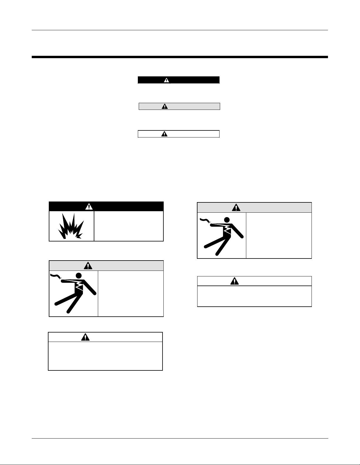
DANGER
Do NOT use in the
presence of flammable
anesthetics.
DANGER
Indicates an imminently hazardous
situation which, if not avoided, WILL
result in death or serious injury.
WARNING
Indicates a potentially hazardous
situation which, if not avoided, COULD
result in death or serious injury.
CAUTION
Indicates a potentially hazardous
situation which, if not avoided may result
in minor or moderate injury.
Additional safety messages may be found throughout this manual that
provide appropria te safe operation inform ation.
WARNING
Keep the conductive
parts of lead electrodes
and associated parts
M15287-1B
away from other
conductive parts,
including earth.
M15287-4C
WARNING
Do NOT contact unit or
patient during
defibrillation.
CAUTION
This equipment contains no user
serviceable parts. Refer servicing to
qualified service personnel.
M15287-8C
M15287-38A
CAUTION
Federal law restricts this device to sale by
or on the order of a physician.
M15287-17A
CAM-14 Acquisition Module
421315-001
Revision A1-4
Page 13

Introduction: Safety Information
Responsibility of the
Manufacturer
Intended Use
General
GE Marquette Medical Sy stems is responsible for th e effects of safety,
reliability, and perfor mance only if:
■ Assembly operations, extensions, readjustments, modifications,
or repairs are carried out by persons authorized by Marquette.
■ The electrical installation of the relevant room complies with
the requirements of the appropriate regulations.
■ The equipment is used in accordance with the instructions for use.
The CAM-14 acquistion module is intended to acquire analog ECG
signal, digitize it and t ransmit the signal t o a host unit. The circuitry is
designed to protect the host unit against the effects of cardiac
defibrillator discharge to ensure recovery.
This device is inten ded for use u nder t he di rect supervi sion of a lice nsed
health care pr actitioner.
This equipment is protected against the effects of cardiac defibrillator
discharge to ensure re covery, as required by test standards.
This equipment will not cause abnormal operation of the patient’s
cardiac pacemaker or other electrical stimulator.
This device uses a computerized ECG analysis program which can be
used as a tool in ECG tracing interpretation. This com puterized
interpretatio n is only significant when used in co njunction with clinical
findings. All computer-generated tracings should be overread by a
qualified physicia n.
To ensure accuracy, use only computer-generated tracings and not the
display for physician int erpretation.
To ensure pati en t safety, use only parts an d a cce ssories manufact ured
or recommended by GE GE Marquette Medical Systems.
Contact GE Marquette Medical Systems for information before
connecting any device s to this equipment that a re not recommended in
this manual.
If the installation of this equipment, in the USA, will use 240 V rather
than 120 V, the source must be a center-tapped, 240 V, single-phase
circuit.
Parts and accessories used must meet the requirements of the
applicable IEC 601 series safety standards, and/or the system
configuration must meet the requirements of the IEC 601-1-1 medical
electrical systems standard.
The use of ACCESSORY equipment not complying with the equivalent
safety requirements of this equipment may lead to a reduced level of
Revision A 1-5
CAM-14 Acquisition Module
421315-001
Page 14

Introduction: Safety Information
safety of the resulting sy st em. Consideration relating to the choice shall
include:
■ use of the accessory in the PATIENT VICINITY; and
■ evidence that the safety certification of the ACCESSORY has
been performed in accordance to the appropriate IEC 601-1
and/or IEC 601-1-1 harmonized national standard.
Equipment Symbols
M13932
The following symbols appear on the equipment.
Type BF equipment. Type BF equipment is suitable for intentional external and
internal application to the patient, excluding a direct conductive connection to the
patient’s heart. Type BF equipment has an F-type applied part. The paddles indicate
that the equipment is defibrillator proof.
CAM-14 Acquisition Module
421315-001
Revision A1-6
Page 15
Service Information
Introduction: Service Information
Service Requirements
Equipment Identification
Refer equipment servicing to GE Marque tte Medical Systems’
authorized service per sonnel only. Any unauthorize d attempt to repair
equipment under warranty voids that warranty.
It is the user’s responsibility to report the need for service to GE
Marquette Medical Systems or to one of their authorized agents.
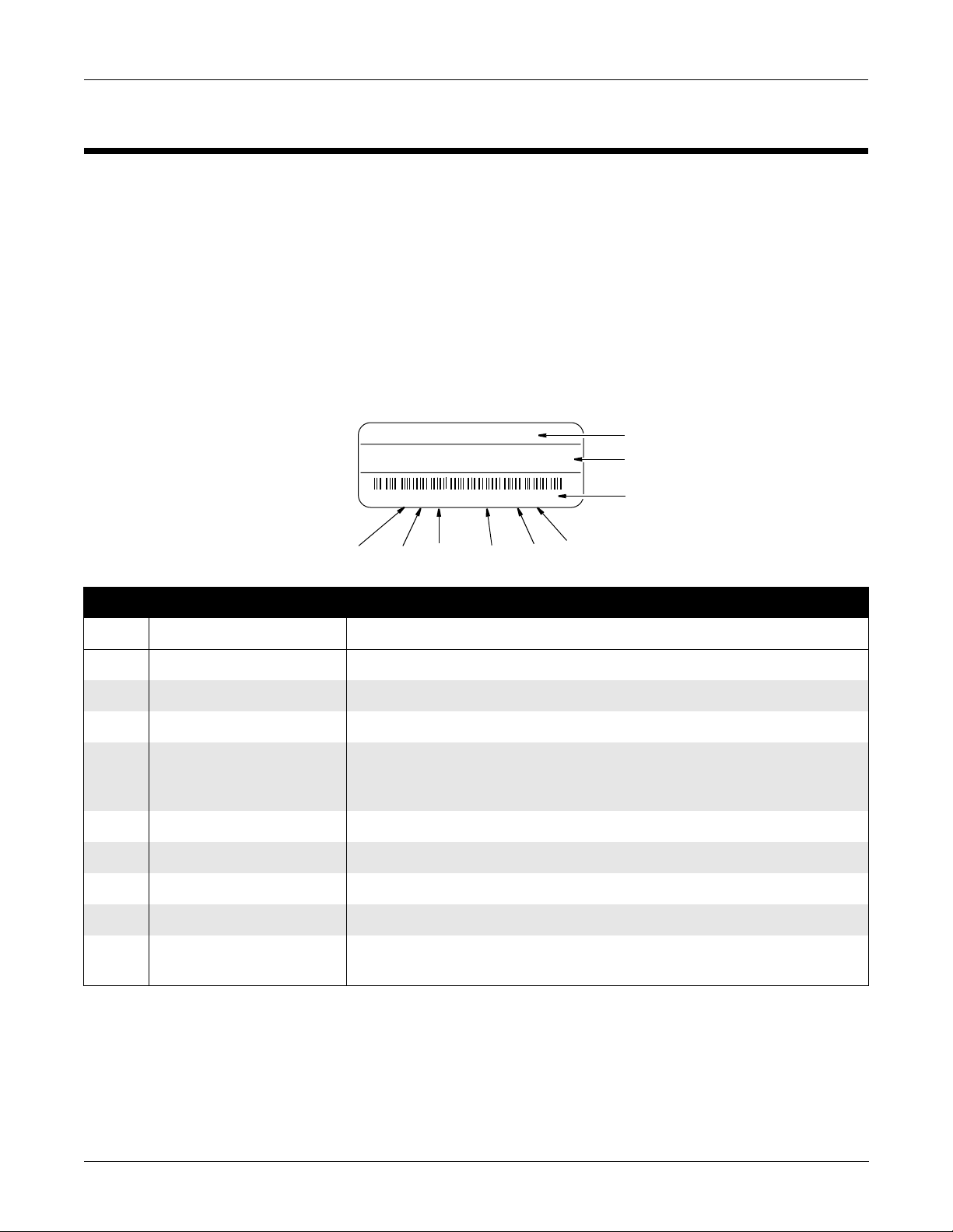
Every GE Marquette Medical Systems device has a unique s erial numbe r
for identification. The serial number appears on the product label on
the base of each unit.
XXXXXXXXX
XXXXXXXX XXXXXXX XXXXXXX XXX
XXXXXXXXX XX XXXX XX XXXXX
J6XX0415FXX
I
Table 2-2. Equipmen t Identifications
Item Name Description
G
H
F
D
E
A
B
C
MD1113-022B
A name of device AM-114 Acquisition Module
B manufacturer GE Marquette Medical Systems, Inc.
C serial number Unique identifier
D device characteristics One or two letters that further describe the unit, for example: P = prototype not
conforming to marketing specification; R = refurbished equipment; S = special
product documented under Specials part numbers; U = upgraded unit
E division F = Cardiology G = Monitoring J = GW Labs
F product sequence number Manufacturing number (of total units manufactured)
G product code Two-character product descriptor MF = CAM-14 Acquisition Module
H year manufactured 7 = 1997, 8= 1998, 9= 1999, (and so on)
I month manufactured A = January, B = February, C = March, D = April, E = May, F = June, G = July,
H = August, J = September, K = October, L = November, M = December
Revision A 1-7
CAM-14 Acquisition Module
421315-001
Page 16

Introduction: Service Information
CAM-14 Acquisition Module
421315-001
Revision A1-8
Page 17

2 Equipment Overview
Technical Characteristics .............................................................. 3
General Description ......................... ....................................... ............... 3
Power Requirements ............................................................................. 4
Operation ................................................................................. 5
Operating Controls ................................................................................. 5
Leadwire Attachments ........................................................................... 5
Leadwire Adapters ....................................................................6
Lead Configurations .................................................................7
Revision A
CAM-14 Acquisition Module
421315-001
2-1
Page 18

2-2
CAM-14 Acquisition Module
421315-001
Revision A
Page 19

Technical Characteristics
Equipment Overview: Technical Characteristics
General Description
The acquisition module performs high resolution ECG data acquisition
for use with host equipment (resting ECG analysis systems and exercise
systems). The acquisition m o du le has the following feature s:
■ ac leadfail bias,
■ l ead off dete ct ion,
■ 4000 Hz sampling rate,
■ patient isolation,
■ software updates via floppy diskette, and
■ Hi-Res analysis on 14-lead units
■ fu nc ti on key cont rol of host equi pme nt fu nc ti ons
The acquisition module provides patient electrical isolation for the host
equipment. The minute ECG s ignal s from th e pati ent’ s skin ar e rec eived
by the electrodes and sent to the acquisition module via leadwires. The
acquisition module then amplifies, digitizes, and performs some
processing on the signals.
This whole process is contro lle d by a microprocessor in the acquisition
module. The acquisition module then sends the serial, digitized, ECG
data to the host equipment in 16 bit “words”. The host equipment
communicates to the acquisition module using this same serial line.
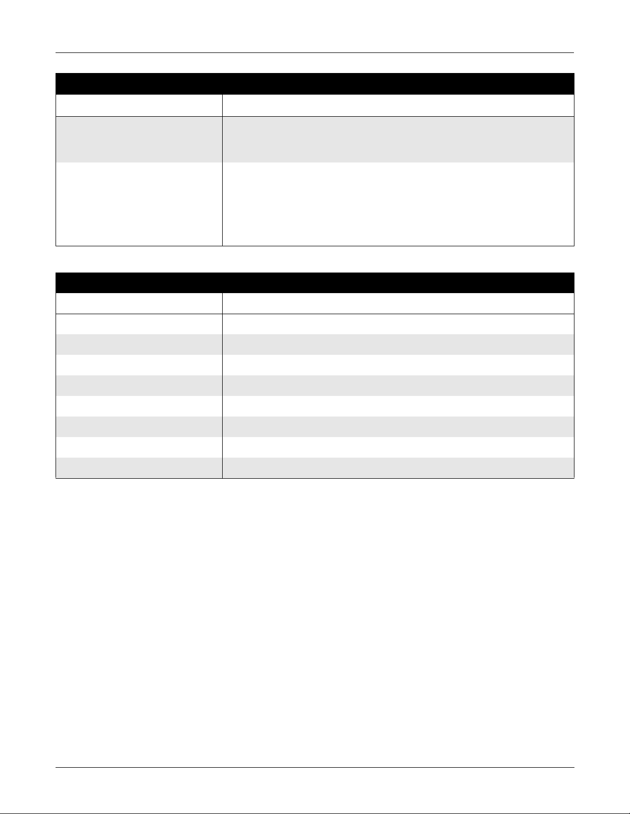
Table 2-1. Safety
Item Description
Certification CE Marking for Council Directive 93/42/EEC
Type of Protection Against Electrical
Not applicable
Shock
Degree of Protection Against Ingress
Ordinary
of Liquids
Handling of Disposable Supplies and
Other Consum ables
■ Use only as manufactured or recommended by Marquette.
■ Follow manufacturer’s instructions for use for disposable/consumable product.
■ Follow local environmental guidelines concerning the disposal of hazardous
materials (e.g. lead acid batteries)
Patient Mode of Operation Continuous
Patient Leakage Current less than 10µA
Degree of Protection Against Electrical
type BF applied parts
Shock
Revision A 2-3
CAM-14 Acquisition Module
421315-001
Page 20
Equipment Overview: Technical Characteristics
Table 2-1. Safety (Continued)
Item Description
Maintenance Frequency ■ Recommended user daily visual inspection and cleaning.
■ Recommended six-month routine maintenance checks and test procedures
performed by qualified technical personnel.
Repair Guidelines Calibration instructions, equi pment descriptions, and all other service informati on to
repair those parts of the equipment designated as field repairable by qualified
technical personnel is available in the service manual.
Upon request, GE Marquette Medical Systems will provide circuit diagrams and
component parts lists for printed circuit boards deemed repairable by qualified
technical personnel.
Table 2-2. Environmental
Item Description
Operating Instructions
Temperature 0°C to 50°C (32°F to 154°F)
Relative Humidity 20% to 95% noncondensing
Atmosphere Pressure 70 to 106 KPa (PRELIMINARY pending final testing)
Storage Conditions
Temperature –20°C to 60°C (–4°F to 172°F)
Relative Humidity 5% to 95% noncondensing
Atmosphere Pressure 50 to 106 KPa (PRELIMINARY pending final testing)
Power Requirements
The acquisition module draws it s power, 12 V dc, from the host unit.
(See the host equipment’s field service manual for the host equ ipment’s
power requirements.) The acquisition module provides the patient
electrical isolation for the host equipment.
CAM-14 Acquisition Module
421315-001
Revision A2-4
Page 21
Operation
Equipment Overview: Operation
Operating Controls
Leadwire Attachments
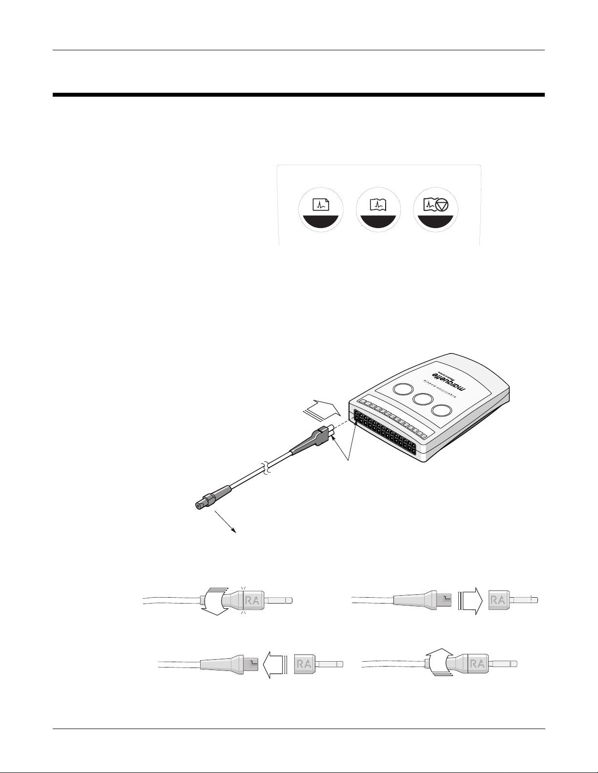
There are three controls on the acquisition module that are
programmed by the host to record an ECG, record a rhythm, or stop the
writer. See the host equipment operator’s manual for the for specific
information on using th e a cquisition module.
2 31
MD1320-002
The leadwires are shown with 2 ends. The figure below shows how to
use both ends of the leadwires. There are various options for leadwire
adapters, the 4 mm pin, stress grabbe r, or MACTR ODE cli p. See cha pte r
5, “Parts Lists and Drawing s” for part numbers.
Flat Surface
Step 1
Step 3
Revision A 2-5
CAM-14 Acquisition Module
421315-001
Step 2
Step 4
MD1320-003B
Page 22
Equipment Overview: Operation
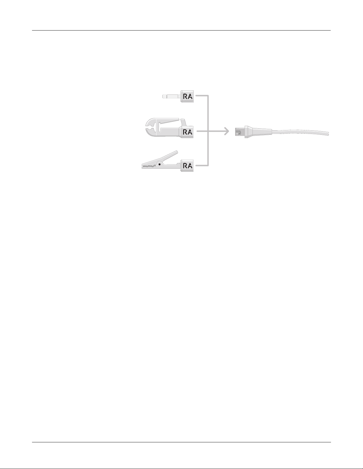
Leadwire Adapters
The acquisition module has universal leadwires which can be made into
any lead of 3 basic types by using the adapters on the ends as shown in
the figure below. The acquisition module leadwire adapters have a
variety of configuration s as shown below. (See chapter 4, “Parts Lists
and Drawings” for part numbers for the various individual leadwire
adapters.)
4 mm Pin
Stress Grabber
MACTRODE Clip
Universal Leadwire End
MD1287-004A
Refer to the figure on the next page for various labels that are affixed to
the acquisition mod ule for these configurations.
CAM-14 Acquisition Module
421315-001
Revision A2-6
Page 23
Equipment Overview: Operation
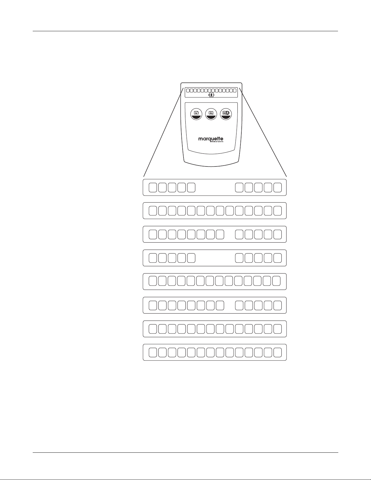
Lead Configurations
10 Lead AHA
14 Lead AHA
The various lead configurations are shown in the figure below. The
acquisition module may be configured in any one of these ways. See
chapter 5, “Parts Lists and Drawings” for part numbers.
N R C1 C2 C3 A1 A2 A3 A4 C4 C5 C6 L F
2 31
acquisition module
RL RA V1 V2 V3 V4 V5 V6 LA LL
HE MRL RA V1 V2 V3 I V4 V5 V6 LA LL
14 Lead AHA Pediatric
10 Lead IEC
14 Lead IEC
14 Lead IEC Pediatric
14 Lead AHA AUX
14 Lead IEC AUX
RL RA V1 V2 V3
V3R V4R
V7 V4 V5 V6 LA LL
N R C1 C2 C3 C4 C5 C6 L F
N R C1 C2 C3 I C4 C5 C6 L F
N R C1 C2 C3
RL RA V1 V2 V3 A1 A2
HE
C3R C4R
C7 C4 C5 C6 L F
A3 A4MV4 V5 V6 LA LL
N R C1 C2 C3 A1 A2 A3 A4 C4 C5 C6 L F
MD1320-004
Revision A 2-7
CAM-14 Acquisition Module
421315-001
Page 24

Equipment Overview: Operation
CAM-14 Acquisition Module
421315-001
Revision A2-8
Page 25

3 Maintenance
Recommended Maintenance .......................................................... 3
General .................................................................................................. 3
Cleaning 3
Exterior Surfaces ......................................................................3
Electrodes .................................................................................3
Visual Checking 4
Built-In Diagnostic Tests 4
Domestic Electrical Safety Tests ...................................................... 5
AC Line Voltage Test .............................................................................. 5
120 VAC, 50/60 Hz ...................................................................5
240 VAC, 50/60 Hz ...................................................................5
Leakage Tests 6
Leakage Test Diagrams 7
Test #1 Ground-wire-leakage-to-ground ...........................................7
Test #2 Chassis-leakage-to-ground .............................................. .....7
Test #3 Patient-cable-leakage-to-ground ..........................................8
Test #4 Patient-cable-leakage-into-patient Leads-from 120 VAC .......8
Ground Continuity 9
Revision A
Disassembly ............................................................................ 10
CAM-14 Acquisition Module
421315-001
3-1
Page 26

3-2
CAM-14 Acquisition Module
421315-001
Revision A
Page 27

Recommended Maintenance
Maintenance: Recommended Maintenance
General
Cleaning
Other than daily cleaning and occasional visual checking, the
acquisition module requires no maintena nce.
Only qualified service personnel should attemp t repairing components
and assemblies int ernal to the acquis ition module. For servic e and
repair, return the acquisition module to the factory for 48-hour turn
around service. Call Tech Support for assistance. (See the “How to
Reach Us” page in the front of the manual.)
NOTE
Unless you have an Equipment Maintenance Contract,
GE Marquette Medical Systems does not in any
manner assume the responsibility for performing the
recommended maintenance procedures. The sole
responsibility rests with the individual or institution
using the equipment. GE Marquette Medical Systems
service personnel may, at their discretion, follow the
procedures provided in this manual as a guide during
visits to the equipment site.
Exterior Surfaces
Electrodes
Disconnect the acquisition module interface cab le from the host
equipment.
■ Use a soft cloth moistened with water and a mild detergent.
Wipe the exterior of the unit, the leadwires, and the acquisition
module interface cable with the damp cloth. Dry all surfaces
with a clean, soft cloth or paper towel.
■ DO NOT allow any excess water to get inside the acquisition
module or onto the leadwires or interface cable.
■ Do not immerse acquisition module in water.
■ Do not use alcohols, organic solvents, or abrasive cleaning
agents.
■ After each use, wipe reusable electrodes with a tissue or damp
cloth to clean them of electrode paste. At the end of each day,
wash reusable electr od es thoroughly with soap and water and
dried.
■ For suction electrodes, use a toothbrush to clean out the cups.
Revision A 3-3
CAM-14 Acquisition Module
421315-001
Page 28

Maintenance: Recommended Maintenance
Visual Checking
Built-In Diagnostic Tests
Inspect the acquisition module each time you clean it or if you suspect a
problem.
■ Check the leadwires and leadwire adapters for wear and loose
connections. Replace these parts at the first sign of wear.
■ Check the pins that the leadwires plug into. They should not be
bent or loose. Contact Tech Support for any repairs needed.
(See the “How to Reach Us” page in the front of the manual.)
■ Check the acquisition module plastic case for any damage.
Contact Tech Support for any repairs needed. (See the “How to
Reach Us” page in the front of the manual.)
The host equi pm ent gene ral ly con tain s b uil t- in di agn ost ic test s to ve ri fy
the operation of the electrocardiograph.
These built-in diagno st ic tests verify the operatio n of the acquisition
module, as well. For example, there is a test that records raw ECG data
on the thermal paper. This test checks for noise and gain in the
acquisition module . Another test is a serial link test that dete rmines if
the microprocessor in the host equipment is communicating with the
acquisition module.
For details on using these tests, see the field service manual for the host
equipment.
CAM-14 Acquisition Module
421315-001
Revision A3-4
Page 29

Domestic Electrical Safety Tests
Maintenance: Domestic Electrical Safety Tests
AC Line Voltage Test
120 VAC, 50/60 Hz
This test verifies that th e domestic wall outlet supp lying power to the
equipment is prope rly wired. For interna tion al wiring tests, refer to the
internal standards agencies of that particular country.
Use a digital voltmeter t o che ck the voltages of the 120-volt AC wall
outlet (dedicated circuit recommended). If the measurements are
significantly out of range, have a qualified electrician repair the outlet.
The voltage measurements should be as follows:
1. 120 VAC (± 10 VAC) between the line contact and neutral and
between the line contact and ground.
2. Less than 3 VAC between neutral and ground.
NEUTRAL
❶
LINE
❶❷
GROUND
MD1287-006
240 VAC, 50/60 Hz
Use a digital voltmeter, set to measure at least 300 VAC, to check the
voltages of the NEMA 6-20R, AC wall outlet (dedicated circuit
recommended). If the measurements are significantly out of range, have
a qualified electrician repair the outlet. The voltage measurements
should be as follows:
1. 120 VAC (± 10 VAC) between either “hot” contact and ground.
2. 210 to 230 VAC between the two “hot” contacts.
HOT
❶
❷
❶
GROUND
HOT
MD1287-007
Revision A 3-5
CAM-14 Acquisition Module
421315-001
Page 30

Maintenance: Domestic Electrical Safety Tests
Leakage Tests
The leakage tests are safety tests to ensure that the equipment poses no
electrical health hazards. Use the table below to determine which tests
apply to the unit under test and the maximum allowable leakage
currents. For international leakage limits, refer to the internal standards
agencies of that particular country.
If the unit under test fails the leakage tests, do not allow the customer to
use the equipment. Call Tech Support for assistance. (See the “How to
Reach Us” page in the front of the manual.)
GE Marquette Medical Systems recommends that you perform these
tests:
■ Before applying power fo r the first time
■ Every 6 months as part of routine maintenance
■ Whenever internal assemblies are serviced
You need a leakage tester to perform the leakage tests.
NOTE
The accuracy of the leakage tests depends on a
properly-wired wall outlet. Do not proceed until you
verify the integrity of the power source.
WARNING
Total system leakage
current must not
exceed 100
microamperes.
M15287-9D
Table 3-1. Leakage Tests and Maximum Allowable Leakage Currents
Test Applies To Maximum Current (µA)
1 Ground-wire-leakage-to-gro un d Host equipmen t 100
2 Chassis-leakage-to-ground Host equipment 100
3 Patient-cable-leakage-to-ground Acquisition module
(patient cable)
4 Patient-cable-leakage-into-patient-leads-from-120 V ac Acquisition module
(patient cable)
10
20
CAM-14 Acquisition Module
421315-001
Revision A3-6
Page 31

Maintenance: Domestic Electrical Safety Tests
Leakage Test Diagrams
Test #1
Ground-wire-leakage-to-ground
Tester
power
Line
Neutral
Gnd
cord
These diagrams show only a representation of how a typical leakage
current tester functions. Follow the instructions provided with the
leakage current tester that you use.
“To be tested” power connector on back of
tester (may not be labeled on some testers).
Tester
connectors
Meter
Polarity
Norm
Rvs
Neutral
1K
Line
Gnd
UUT
power
cord
Unit
under
test
(UUT)
Test #2
Chassis-leakage-to- ground
Tester
power
Line
Neutral
Gnd
cord
V
Apply line voltage to the UUT chassis for th is t est.
“To be tested” power connector on back of
tester (may not be labeled on some testers).
Tester
Meter
connectors
Polarity
Norm
Rvs
Neutral
1K
Line
Gnd
UUT
power
cord
Probe to
exposed chassis
Unit
under
test
(UUT)
MD1287-008
V
MD1287-009
Revision A 3-7
CAM-14 Acquisition Module
421315-001
Page 32

Maintenance: Domestic Electrical Safety Tests
Test #3
Patient-cable-leakage-to-ground
Line
Neutral
Gnd
Tester
power
cord
Tester
Meter
connectors
Polarity
Norm
Rvs
Line
Neutral
Gnd
1K
V
Patient
cable connectors
“To be tested” power connector on back of
tester (may not be labeled on some testers).
UUT
power
cord
Unit
under
test
(UUT)
Patient cable
MD1287-010
Test #4
Patient-cable-leakage-into-patient
Leads-from 120 VAC
Tester
power
Line
Neutral
Gnd
cord
During this test, line voltage is applied to the patient cable connectors.
To prevent errone ous readings, do not allow the leadwires to contact
conductive materials such as metal handles, and do not place the
leadwires on the floor.
“To be tested” power connector on back of
tester (may not be labeled on some testers).
Tester
Meter
connectors
Polarity
Norm
Rvs
Line
Neutral
Gnd
1K
V
Patient
cable connectors
UUT
power
cord
Patient cable
Unit
under
test
(UUT)
MD1287-011
CAM-14 Acquisition Module
421315-001
Revision A3-8
Page 33

Maintenance: Domestic Electrical Safety Tests
Ground Continuity
This test verifies that there is continuity (less than 100 mΩ resistance)
between all the exposed metal surfaces on the host equipment, which
have the potential to become energized, and the ground prong on the
mains AC power cord. If the metal surfaces are anodized or painted,
scrape off a small ar e a in an inconspicuous area for the probe to make
direct contact with the metal.
Use a digital multimeter to check all the metal surface s of the host
equipment. Make ad justments for any res istance in the test leads. (See
the host equipment field service manual for detailed information.)
If the measurements are significantly out of range, check for breaks in
the power cord or in the internal connections within the unit.
Revision A 3-9
CAM-14 Acquisition Module
421315-001
Page 34

Maintenance: Disassembly
Disassembly
Strict antistatic prec autions should be followed during disassembly/
assembly of the CAM-14.
NOTE
Use the proper ESD grounding techniques when
handling components. Wear an antistatic wrist strap
and an ESD protected mat. Store ESD sensitive
components in antistatic bags before placing them on
any surface.
Cover
Gently disconnect flex
cable from switch
before removing cover
Switch flex cable
Host cable
interface flex
#6 Torx screws
Follow the steps below when disassemblin g t he CA M-14.
1. Remove the four Torx screws holding the top and bottom of the
CAM-14 unit together us ing a #6 TORX driver.
2. Lift the top only high enou gh to allow access to the switch flex
cable from the switch as sembly.
MD1320-006
CAM-14 Acquisition Module
421315-001
Revision A3-10
Page 35

Maintenance: Disassembly
3. To avoid damage to the flex cable, gently pry the cable off the
switch at the main pcb with a small screwdriver.
NOTE
Damage to the switch flex cable connector will result in
failure of one or more of the switch functions.
■ DO NOT attempt to disconnect the switch flex
cable by pulling on it.
■ DO NOT let the main pcb hang by the cable.
4. When the main pcb has been separated from the switch flex
cable, disconnect the host cable interface flex from the main
pcb by gently prying the connectors apart.
Revision A 3-11
CAM-14 Acquisition Module
421315-001
Page 36

Maintenance: Disassembly
CAM-14 Acquisition Module
421315-001
Revision A3-12
Page 37

4 Parts Lists and Drawings
Ordering Parts ......................................................................... 3
Introduction ........................................................................................... 3
900995-001A Acquisition Module Assembly .................................... 4
420101-001B 14 Leadwire Kit ..................................................... 7
417483-9XXA Leadwire, Multi-Link, Universal ................................ 8
900179-201 Leadwire Adapter Kit - Banana ................................ 10
900179-202 Leadwire Adapter Kit - Mactrode .............................. 11
900179-203 Leadwire Adapter Kit - Grabber ................................ 12
Revision A
CAM-14 Acquisition Module
421315-001
4-1
Page 38

4-2
CAM-14 Acquisition Module
421315-001
Revision A
Page 39

Ordering Parts
Parts Lists and Drawings: Ordering Parts
Introduction
This chapter provides upper-level drawings for the standard
configurations of the acquisition module and any kit s which are
available. It includes enough detail to provide part numbers for fieldserviceable assem blies in the equipmen t.
Subassembly drawings follow the upper-le vel drawings and are
arranged in asce nding numerical order. The assembly drawings
generally include both a parts lists and an exploded view.
To order parts, contact Ser vice Pa rts at the addr ess or te lephone num ber
on the “How to Reach Us…” page at the beginning of this manual.
Revision A 4-3
CAM-14 Acquisition Module
421315-001
Page 40

Parts Lists and Drawings: 900995-001A Acquisition Module Assembly
900995-001A Acquisition Module Assembly
Item Description Part Number Qty.
1 PCB CAM 14 MAIN BRD 801280-001 1
2 PCB CAM14 CABLE INTFC 801502-001 1
3 ASSY TOP W/ SWITCH CAM 14 422 032-001 1
4 ASSY WELD BTM BELT CL IP CAM 14 420148-001 1
5 LABEL NEW ACQ MOD LD CODES 420152-001 1
6 KIT LDWR AM11X SET 14 420101-001 1
7 LABEL CLEAR OVERLAMINATE 413608-001 1
8 LABEL CAM 14 BOTTOM 419979-001 1
9 SCREW 1 X .375 TORX T-6 FHPH 417866-002 4
10 CARTON, MAILER 11X5X3 CAM 14 421927-001 1
11 INSERT, DIE CUT CAM 14 421927-002 1
12 I-STATIC, 6.00W x 8.00 L (not shown) 9976-005 1
13 PTR 14 SET AHA BANANA 900179-201 1
1
CAM-14 Acquisition Module
421315-001
Revision A4-4
Page 41

Parts Lists and Drawings: 900995-001A Acquisition Module Assembly
5
3
2
9
Notes:
1. Model/Serial # Label to be Marked:
CAM 14
(Serial # TBD)
1
4
8
7
Revision A 4-5
CAM-14 Acquisition Module
421315-001
Page 42

Parts Lists and Drawings: 900995-001A Acquisition Module Assembly
11
11
6
Place Leadwire Kit
(Item 6) into Card
Board Insert
Place Leadwire Adapter Kit
13
(Item 13) into Card
Board Insert
LEAD
ADAPTER
KIT
LEAD
WIRE
KIT
10
5
Place unused
Labels into
Carton
CAM-14 Acquisition Module
421315-001
Revision A4-6
Page 43

Parts Lists and Drawings: 420101-001B 14 Leadwire Kit
420101-001B 14 Leadwire Kit
Item Description Part Number Qty
1 BAG, ANTISTATIC 6 X 8 9976-005 1
2 LEADWIRE UNIV/MLINK AM11X 26” 417483-905 10
3 LEADWIRE UNIV/MLINK AM11X 36” 417483-906 2
4 LEADWIRE UNIV/MLINK AM11X 40” 417483-903 2
5 INSERT/REORDER CARD 70357-001 1
Revision A 4-7
CAM-14 Acquisition Module
421315-001
Page 44

Parts Lists and Drawings: 417483-9XXA Leadwire, Multi-Link, Universal
417483-9XXA Leadwire, Multi-Link, Universal
Item Description Part Number Qty
1 TUBING FIT-221 3/32 BLK 4882-103 0.04
2 RESIN ABS NATURAL 5421-001 A/R
3 RESIN PVC 60 DURO NATURAL 5423-001 A/R
4 RESIN PVC 85 DURO NATURAL 5423-002 A/R
5 MOLD UNIVERSAL PRE MO LD AM4 58973-058 1
6 MOLD STRAIN RELIEF AM4 WIRE 58973-059 1
7 INSERT MOLDED AM4 LEADWIRE 58973-060 1
8 LDWR PLUGFACE INDV MULTILINK DGRAY 411191-004 1
9 PLUG PREMOLD INDV LDWR MULTILINK 411192-900 1
10 PLUG OVERMOLD INDV LDWR MULTILINK 411193-001 1
11 LEADWIRE CONTACT 411197-001 3
12 BAND SPLICE 412201-001 1
13 COLORANT MULTIPURPOSE DARK GRAY 412793-028 A/R
14 CABLE COAX 1 COND 26 AWG. 125 OD PVC 700136-007 A/R
CAM-14 Acquisition Module
421315-001
Revision A4-8
Page 45

Parts Lists and Drawings: 417483-9XXA Leadwire, Multi-Link, Universal
LENGTH CHART
REV SUFFIX
-901 20"/1.70 FT
A
-902 29"/2.45 FT
A
-903 40"/3.35 FT
A
-904 51"/4.25 FT
A
A
A
711
ITEM 16
DIM "A"
INCHES/FEET
26"/2.17 FT-905
36"/3.0 FT-906
5
2
13
6
3
4
13
Termination Detail
Premold Detail
Overmold Detail
13
10
13
14
12
Do Not Cover Contact
.40" Only over Shield
1
11
2
9
3
Pin No. 2
Shield
4
8
Month Lot Code
See Note 2
Pin No. 1
Center
Conductor
Dim "A" ±1.00 (See Chart)
Finished Part Detail
Notes:
1. For Overmold Mix PVC Resins Items 3 & 4 together to obtain 72 ±5 Durometer.
Color: Gray, Munsell N7.
2. Month Lot Code: One letter in alphabetical order for each month where A = January,
B = February . . . Skip letter "I".
Year Lot Code: One digit, the last digit of the year where 7 = 1997, 8 = 1998 . . .
3. Performance Specification:
Hi-Pot: Wire must withstand 5000 VDC 1 mA for 1 second between center
Conductor and Shield.
Continuity Test: Leadwire to be tested end to end between universal End & Center
Conductor.
4. Finished Assembly to be free of dirt. Discolorations or other signs of poor
workmanship. Molded Components to have Flash and Gate Marks trimed flush to
within .010 of surface.
Revision A 4-9
CAM-14 Acquisition Module
421315-001
Page 46

Parts Lists and Drawings: 900179-201 Leadwire Adapter Kit - Banana
900179-201 Leadwire Adapter Ki t - Banana
Item Description Part Number Qty
1 ASSY BANNANA RL GREEN 406554-007 1
2 ASSY BANNANA RA WHITE 406554-001 1
3 ASSY BANANA LL RED 406554-005 1
4 ASSY BANANA LA BLACK 406554-003 1
5 ASSY BANANA V1 BROWN 406554-009 1
6 ASSY BANANA V2 BROWN 406554-011 1
7 ASSY BANANA V3 BROWN 406554-013 1
8 ASSY BANANA V4 BROWN 406554-015 1
9 ASY BANANA V5 BROWN 406554-017 1
10 ASSY BANANA V6 BROWN 406554-019 1
11 ASSY BANANA E ORANGE 406554-021 1
12 ASSY BANANA H ORANGE 406554-023 1
13 ASSY BANANA I ORANG 406554-025 1
14 ASSY BANANA M ORANGE 406554-027 1
CAM-14 Acquisition Module
421315-001
Revision A4-10
Page 47

Parts Lists and Drawings: 900179-202 Leadwire Adapter Kit - Mactrode
900179-202 Leadwire Adapter Ki t - Mactrode
Item Description Part Number Qty
1 ASSY MACTRODE RL GREEN 406551-007 1
2 ASSY MACTRODE RA WHITE 406551-001 1
3 ASSY MACTRODE LL RED 406551-005 1
4 ASSY MACTRODE LA BLACK 406551-003 1
5 ASSY MACTRODE V1 BROWN 406551-009 1
6 ASSY MACTRODE V2 BROWN 406551-011 1
7 ASSY MACTRODE V3 BROWN 406551-013 1
8 ASSY MACTRODE V4 BROWN 406551-015 1
9 ASY MACTRODE V5 BROWN 406551-017 1
10 ASSY MACTRODE V6 BROWN 406551-019 1
11 ASSY MACTRODE E ORANGE 406551-021 1
12 ASSY MACTRODE H ORANGE 406551-023 1
13 ASSY MACTRODE I ORANG 406551-025 1
14 ASSY v MACTRODE M ORANGE 406551-027 1
Revision A 4-11
CAM-14 Acquisition Module
421315-001
Page 48

Parts Lists and Drawings: 900179-203 Leadwire Adapter Kit - Grabber
900179-203 Leadwire Adapter Kit - Grabber
Item Description Part Number Qty
1 ASSY GRABBER RL GREEN 406552-007 1
2 ASSY GRABBER RA WHITE 406552-001 1
3 ASSY GRABBER LL RED 40655 2- 005 1
4 ASSY GRABBER LA BLA CK 406552-003 1
5 ASSY GRABBER V1 BROWN 406552-009 1
6 ASSY GRABBER V2 BROWN 406552-011 1
7 ASSY GRABBER V3 BROWN 406552-013 1
8 ASSY GRABBER V4 BROWN 406552-015 1
9 ASY GRABBER V5 BROWN 406552-017 1
10 ASSY GRABBER V6 BROWN 406552-019 1
11 ASSY GRABBER E ORANGE 406552-021 1
12 ASSY GRABBER H ORANGE 406552-023 1
13 ASSY GRABBER I ORANG 406552-025 1
14 ASSY v GRABBER M ORANGE 406552-027 1
CAM-14 Acquisition Module
421315-001
Revision A4-12
Page 49

5 PCB Assemblies
8001280-001A Data Acquisition Module .......................................... 3
SD8001280-001A Schematic, Main Board ........................................... 8
Revision A
CAM-14 Acquisition Module
421315-001
5-1
Page 50

5-2
CAM-14 Acquisition Module
421315-001
Revision A
Page 51

PCB Assemblies: 8001280-001A Data Acquisition Module
8001280-001A Data Acquisition Module
Item Description Part Number Qty.
1 RES COMP 100M 5% 1/4W 1001-107 2
2 RES SM CER 100 5% 1/8W 1081-101 1
3 RES SM CHIP 5% 1/8W 51 OHMS 1081-472 1
4 RES SM CER 26.7 1% 1/8W 1082-909 1
5 CAP SM CER COG 150PF 5% 50V 1181-151 13
6 CAP SM CER X7R .1UF 50V 1187-104 2
7 DIODE SM SERIES PR D7000 2013-201 4
8 DIODE SM SCHTKY BARRIER 2800 2412-001 1
9 DIODE SM LL FDSO1503 2414-001 14
10 IC SM HC 74HC161 3038-161 1
11 IC SM SSOP VHC04 3057-004 1
12 IC SM SSOP VHC573 3057-573 1
13 DIODE SM ZENER 5234 6.2V 401502-001 2
14 CAP SM TANT 1.0UF 10% 16V 406883-002 3
15 CAP SM TANT 10UF 10% 35V 406884-013 3
16 IC SM DUAL N-CHAN MFET SI9955 407547-001 1
17 BEAD SM 1206 600@100 200MA 408746-001 3
18 IC SM HCMOS TC7S02F 408795-001 2
19 IC SM OPTOCOUPLER CNW2611 408825-001 2
20 IC SM HCMOS AND TC7S08F 409035-001 2
21 RES SM 0603 100 1% 1/16W 410334-003 1
22 RES SM CER 0603 10K 1% 1/16W 410334-013 22
23 RES SM 0603 11.5K 1% 1/16W 410334-014 1
24 RES SM 0603 3.01K 1% 1/16W 410334-018 13
25 RES SM 0603 100K 1% 1/16W 410334-019 7
26 RES SM CER 0603 0 OHM JUMPER 410334-027 1
27 RES SM 0603 511 OHM 1% 1/16W 410334-034 1
28 RES SM 0603 47.5K 1% 1/16W 410334-036 1
29 RES SM 0603 200 OHM 1% 1/16W 410334-044 2
30 RES SM 0603 7.68K 1% 1/16W 410334-049 1
31 RES SM 0603 20.0K 1% 1/16W 410334-053 6
32 RES SM CER 0603 4.99K 1% 1/16W 410334-066 1
33 RES SM CER 0603 35.7K 1% 1/16W 410334-091 2
34 RES SM 0603 7.87K 1% 410334-098 3
35 RES SM 0603 750 1% 410334-099 3
36 RES SM 0603 1.24K 1% 410334-101 1
37 RES SM 0603 30.1 1% 1/16W 410334-109 1
38 RES SM 0603 2.49K 1% 1/16W 410334-110 7
39 RES SM CER 0603 8.06K 1% 1/16W 410334-113 2
Revision A 5-3
CAM-14 Acquisition Module
421315-001
Page 52

PCB Assemblies: 8001280-001A Data Acquisition Module
Item Description Part Number Qty.
40 RES SM 0603 1.0M 1% 1/16W 410334-120 3
41 RES SM 0603 33.2K 1% 1/16W 410334-165 1
42 RES SM 0603 249K 1% 1/16W 410334-186 2
43 RES SM 0603 15.8K 1% 1/16 410334-225 12
44 CONN BLK,CAM 14 14POS W/10K R 411305-003 1
45 CAP SM X7R 0603 .1UF 10% 16V 411575-002 80
46 CAP SM X7R 0603 1000PF 5% 50V 411575-003 2
47 CAP SM X7R 0603 390PF 5% 50V 411575-009 1
48 CAP SM X7R 0603 2700PF 5% 50V 411575-010 2
49 CAP SM X7R 0603 0.01UF 5% 50V 411575-012 2
50 CAP SM X7R 0603 .022UF 16V 5% 411575-014 4
51 CAP SM X7R 0603 220PF 5% 50V 411575-022 4
52 CAP SM X7R 0603 3300PF 5% 50V 411575-024 1
53 CAP SM NPO 0603 100PF 5% 50V 411575-025 2
54 CAP SM X7R 0603 2200PF-5% 411575-033 3
55 CAP SM NPO 0603 33PF 5% 50V 411576-004 1
56 CAP SM NPO 0603 5.6PF +/-25PF 411576-017 13
57 CAP SM NPO 0603 470PF 5% 50V 411576-018 3
58 CAP SM X7R 0805 .047UF 5% 25V 411587-004 1
59 IC SM DUAL OP AMP TLC272CD 411710-001 1
60 RES SM 0603 10M 5% 1/16W 411723-003 1
61 SM RESONATOR 4MHZ TYPE KBR 412010-001 1
62 IC SM OPTOCOUPLER CNW136 412017-001 1
63 CAP SM TANT 220UF 20% 10V 412662-002 2
64 CAP SM TANT 33UF 20% 25V 412662-003 1
65 IC SM OP AMP AD822 412753-001 1
66 IC SM OP AMP LOW POWER AD82O 412799-001 1
67 CAP SM TANT 3.3UF 10% 10V 413119-001 1
68 DIODE SM SCHTKY RECT MBR0520 413970-001 2
69 SM FERRITE BEAD 0603 BLM11A601 414061-001 5
70 CAP SM TANT 2.2UF 10V 10% 414084-001 2
71 IC SM PWM CONTROLLER UCC3806DW 414247-001 1
72 IC SM 4.85V REG MIC5201 416998-001 1
73 IC RS485/422 XCVR MAX490 SO8 417913-001 1
74 CONN SCKT SM B/B 2MM HGT 10POS 417955-001 2
75 TRANSFORMER TNI ISO T8175 418434-001 1
76 IC SM DSP TMS320F206 PQFP 419051-001 1
77 IC SM D FLIP TC7W74FU 419131-001 1
78 IC SM AV9170-02 419133-001 1
79 IC SM OP AMP TLV2221 SOT23-5P 419134-001 13
80 IC SM TPS 5904 419135-001 1
81 IC SM MAX4051 419283-001 2
CAM-14 Acquisition Module
421315-001
Revision A5-4
Page 53

PCB Assemblies: 8001280-001A Data Acquisition Module
Item Description Part Number Qty.
82 IC SM INSTR AMP INA126E SSOP 419315-002 12
83 IC SM QUAD OP-AMP 34184 TSSOP 419383-001 1
84 RES SM CHIP 0.2 5% 0.2W 419604-001 1
85 IC SM PWR SPLY MONMAX823 419699-002 1
86 IC SM ADS7809 16 BIT A/D 419952-001 1
87 POST SM 1MM MALE 2X7 420007-007 1
88 FRMWR COMMAND INTERFACE V001A 421920-001 1
89 CKT BD CAM 14 MAIN BD 801281-001 1
90 SCHEM CAM14 MAIN BRD SD801280-001 0
Drawing notes:
■ Unless otherwise specified, all resistors are 10K, 1%; all
capacitors are 0.1µF, 10%; all diodes are FDS01503; all ICs are
INA126E.
■ The bar shown on all polarized capacitors denotes the positive
terminal.
■ Parts not installed (solder side): R29, R30.
■ Trim leads of R224 and R225 in the indicated area so they do
not extend beyond edge of solder pad.
Revision A 5-5
CAM-14 Acquisition Module
421315-001
Page 54

PCB Assemblies: 8001280-001A Data Acquisition Module
Component (Top) View
CAM-14 Acquisition Module
421315-001
Revision A5-6
Page 55

PCB Assemblies: 8001280-001A Data Acquisition Module
Solder (Bottom) Side
Revision A 5-7
CAM-14 Acquisition Module
421315-001
Page 56

PCB Assemblies: SD8001280-001A Schematic, Main Board
SD8001280-001A Schematic, Main Board
1 of 13
CAM-14 Acquisition Module
421315-001
Revision A5-8
Page 57

PCB Assemblies: SD8001280-001A Schematic, Main Board
Revision A 5-9
CAM-14 Acquisition Module
421315-001
Page 58

2 of 13
PCB Assemblies: SD8001280-001A Schematic, Main Board
CAM-14 Acquisition Module
421315-001
Revision A5-10
Page 59

PCB Assemblies: SD8001280-001A Schematic, Main Board
Revision A 5-11
CAM-14 Acquisition Module
421315-001
Page 60

PCB Assemblies: SD8001280-001A Schematic, Main Board
3 of 13
CAM-14 Acquisition Module
421315-001
Revision A5-12
Page 61

PCB Assemblies: SD8001280-001A Schematic, Main Board
Revision A 5-13
CAM-14 Acquisition Module
421315-001
Page 62

PCB Assemblies: SD8001280-001A Schematic, Main Board
4 of 13
CAM-14 Acquisition Module
421315-001
Revision A5-14
Page 63

PCB Assemblies: SD8001280-001A Schematic, Main Board
Revision A 5-15
CAM-14 Acquisition Module
421315-001
Page 64

PCB Assemblies: SD8001280-001A Schematic, Main Board
5 of 13
CAM-14 Acquisition Module
421315-001
Revision A5-16
Page 65

PCB Assemblies: SD8001280-001A Schematic, Main Board
Revision A 5-17
CAM-14 Acquisition Module
421315-001
Page 66

PCB Assemblies: SD8001280-001A Schematic, Main Board
6 of 13
CAM-14 Acquisition Module
421315-001
Revision A5-18
Page 67

PCB Assemblies: SD8001280-001A Schematic, Main Board
Revision A 5-19
CAM-14 Acquisition Module
421315-001
Page 68

PCB Assemblies: SD8001280-001A Schematic, Main Board
7 of 13
CAM-14 Acquisition Module
421315-001
Revision A5-20
Page 69

PCB Assemblies: SD8001280-001A Schematic, Main Board
Revision A 5-21
CAM-14 Acquisition Module
421315-001
Page 70

PCB Assemblies: SD8001280-001A Schematic, Main Board
8 of 13
CAM-14 Acquisition Module
421315-001
Revision A5-22
Page 71

PCB Assemblies: SD8001280-001A Schematic, Main Board
Revision A 5-23
CAM-14 Acquisition Module
421315-001
Page 72

PCB Assemblies: SD8001280-001A Schematic, Main Board
9 of 13
CAM-14 Acquisition Module
421315-001
Revision A5-24
Page 73

PCB Assemblies: SD8001280-001A Schematic, Main Board
Revision A 5-25
CAM-14 Acquisition Module
421315-001
Page 74

PCB Assemblies: SD8001280-001A Schematic, Main Board
10 of 13
CAM-14 Acquisition Module
421315-001
Revision A5-26
Page 75

11 of 13
PCB Assemblies: SD8001280-001A Schematic, Main Board
Revision A 5-27
CAM-14 Acquisition Module
421315-001
Page 76

PCB Assemblies: SD8001280-001A Schematic, Main Board
CAM-14 Acquisition Module
421315-001
Revision A5-28
Page 77

12 of 13
PCB Assemblies: SD8001280-001A Schematic, Main Board
Revision A 5-29
CAM-14 Acquisition Module
421315-001
Page 78

PCB Assemblies: SD8001280-001A Schematic, Main Board
CAM-14 Acquisition Module
421315-001
Revision A5-30
Page 79

13 of 13
PCB Assemblies: SD8001280-001A Schematic, Main Board
Revision A 5-31
CAM-14 Acquisition Module
421315-001
Page 80

PCB Assemblies: SD8001280-001A Schematic, Main Board
CAM-14 Acquisition Module
421315-001
Revision A5-32
Page 81

A Appendix A:
Abbreviations
Standard Abbreviations ................................................................. 3
Revision A
CAM-14 Acquisition Module
421315-001
A-1
Page 82

A-2
CAM-14 Acquisition Module
421315-001
Revision A
Page 83

Standard Abbreviations
A
Aampere
A-ang antianginal
A-arh antiarrhythmic
A-coa anticoagulants
A-hyp antihypertensive
A1 - A4 auxiliary leadwires
AAMI American Association of Medical
Instrumentation
ABP ambulatory blood pressure
ac, AC alternating current
ACLS Advanced Cardiac Life Support
A/D analog-to-digital
Adj adjustable
AG automotive glass
Ah ampere hou rs
AHA American Heart Association
Al aluminum
AllRam all RAM
AllSec all sector
AllTrk all track
ALT alternate
Alt-Off alternate offset
am, AM acquisition module, ante meridiem
AM-1 acquisition module-1
AM-1M acquisition module-1 modified
AM-2 acquisition module-2
AM-3 acquisition module-3
AM-4 acquisition module-4
amp ampere
Ampl amplifier
AMU ambulatory monitoring unit
ANA analog
ANLG analog
AnsrTone answer tone
A/O Analog Output
ASCII American Standard Code for Information
Interchange
ASSY assembly
Attn attention
AUG August
AUST Australian
AUSTRALN Australian
Auto automatic
AutoRhym automatic rhythm
AUX auxiliary
aVF augmented left leg lead
avg average
aVL augmented left arm lead
aVR augmented right arm lead
AWG American Wire Gage
B
Bd board, baud
BDGH binding head
BetaB beta blockers
BKSP backspace
BLK black
BLU blue
Blvd boulevard
BP blood pressure
BPM beats per minute
BRIT Britain
BRN brown
BSI British Standards Institute
Btu British thermal unit
C
CalcBlk calcium blockers
CAPOC Computer Assisted Practice of
Cardiology
CASE Computer Aided System for Exercise
Catoprl Catopril
Cauc Caucasian
Cer ceramic
CFM cubic feet/minute
CGR computer graphic record
Ch, CH channel
C/L center line
CLK clock signal
Clonid Clonidine
cm centimeter
cm2 square centimeters
Cmd command number
CMMR common mode rejection ratio
CMOS complementary metal-oxide
semiconductor
c/o in care of
COM1 communications port 1
COM2 communications port 2
ComLink communications link
Comp composition
Confrmd confirmed
Cont, CONT Continent a l, continued
Coumadn Coumadin
CPR cardiopulmonary resuscitation
CPU central processing unit
CR diode
Revision A A-3
CAM-14 Acquisition Module
421315-001
Page 84

CRC cyclic redundancy check
CRD cord
crt, CRT cathode ray tube
CSA Canadian Standards Association
CTRL control
D
D/A digital to analog
DA damping relay
dac, DAC digital-to-analog converter
DAN Danish
Dat/Tim date/time
dBm decibel (referenced to 1 milliwatt into
600 ohms)
dc, DC direc t current
DD double density, day
DDD Digital Diagnostic Diskette
DEC Digital Equipment Corporation,
December
Del delete
DEMO demonstration
DES designation
DevId device identification
Diag diagnostic
Digital Digitalis
Digitox Digitoxin
Digox digoxin
Digoxin Digoxin-Lanoxin
DIP dual in-line package
Dirctry directory
Diurt diuretics
DOB date of birth
DOS disk operating system
DP diametral pitch
DPST double-pole, single-throw
DRAM dynamic RAM
DR/DT digital recording/digital transmission
DSKTP desktop
Dysopyr Dysopyramide
E
EPLD electrically programmable logic device
EPROM eraseable, programmable, read-only
memory
ESD electrostatic discharge
etc, etc. et cetera
EURO Europe, European
EXP Expanded
F
F fuse, Farad, female
F1-F5 function keys 1 through 5
Fax facsimile
FCC Federal Communications Commission
FE front end
FILH fillister head
FLH flat head
FLRAM flash RAM
FR French
FrntEnd front end
FSK frequency shift keying
ft foot, feet
Furosem Furosemide
G
g gram, acceleration due to gravity
GB Great Britain
GERM German, Germany
GND ground, digital ground (dc common)
GRN green
GRY gray
H
H high, vector electrode site, vector lead
HDLC high-level data link control
Hex, HEX hexagon, hexadecimal
HH hour
HiRes high-resolution
Hr hour
Hydral Hydralazine
Hz Hertz (cycles per second)
E enable, vector electrode site, vector lead
ecg, Ecg, ECG electrocardiogram
ECO Engineering Change Order
EDIC Electrocardiograph Digital Inform ation
Center
EEPROM electrically erasable programmable ROM
e.g. for example
EGA enhanced graphics adapter
EMF electromotive force
EMI electromagnetic interference
ENG English
EOF end of file
EPIC Electronic Patient Information Chart
CAM-14 Acquisition Module
421315-001
I
I on, input, vector electrode site
I, II, III limb leads
II vector lead
IC integrated circuit
ID identification
i.e. that is
IEC International Electrotechnical Commission
in inch
IN input
inc, inc., INC incorporated
Info information
Revision AA-4
Page 85

Ins insert
I/O input/ ou tp ut
I/P input
ISA industry standard architecture
Isosorb Isosorbide
IT Italian, Italy
J
JAN January
JIS Japan Industrial Standards
K
k, K kilo, 1000, 1024
Kb, KB kilobyte
kg, Kg kilogram
kHz, KHz kilohertz
kV, KV kilovolt
Kyb keyboard
L
Lline
L1 level one
L2 level two
LA left arm
lb pound
LCD liquid crystal display
Lcl Line local line
Ld Grps lead groups
LED light-emitting diode
LH left hand
Lidoca Lidocaine
LL left leg
Loc location
LocPc Local MAC PC
LogRetry log retry
Ltd limited
M
m meter
M megabyte, metric, vector electrode site,
vector lead, male
mA milliamperes
MAC Microcomputer Augmented Cardiograph
mains voltage voltage of a supply mains between 2 line
conductors of a polyphase system or
voltage between the line conductor and
the neutral of a single-phase system
max maximum
Measure measurements
Med medications
MEM memory
MF metal film
MHz megahertz
min minutes, minimum
Misc miscellaneous
mm millimeter
MM minute
MMM month
mm/mV millimeter per millivolt
mm/s millimeter per second
MMS Marquette Medical Systems
Modem modulator/demodulator
MOS metal oxide semiconductor
MPE metallized polycarbonate expitaxial
ms milliseconds
MS-DOS Microsoft Disk Operating System
MTBF mean time between failures
mtg mounting
MTR MOTOR
MUSE Marquette Universal System for
Electrocardiography
mux multiplexer
mV millivolt
mVR minus (inverted) aVR
N
N neutral
n/a not available
NA not applicable
NC no connection
Nitrate nitrates
NLQ near letter quality
NMI non-maskable interrupt
NMOS N-channel metal-oxide semiconductor
No number
NO normally open
norm no rmal
nS nanoseconds
NSR Normal Sinus Rhythm
O
O off, original
OE other errors
OEM original equipment manufacturer
OH off-hook relay
OneSec one sector
ORG orange
Orig original
OUT output
oz ounce
P
P P wave (section of the ECG waveform)
p-p peak-to-peak
PA P wave amplitude
Params parameters
Revision A A-5
CAM-14 Acquisition Module
421315-001
Page 86

Passwds passwords
PatData patient data
PatInfo patient information
PATN patient
PC printed circuit, personal computer
PCB printed circuit board
pF picofarad
Pgm program
PgmId program identification
Phenoth Phenothiazide
Phenytn Phenytoin
PID patient identification digit
PLCC plastic leadless chip carrier
PM power module
pm, PM post meridiem, preventive maintenance
PM-2 Power Module-2
PM-3 Power Module-3
pn, PN part number
PNH pan head
PPA P wave amplitude
PR ECG signal interval
Pro-Off progressive offset
Procain Procainamide
PROM programmable read-only memory
Propran Propranolol
PSK phase shift keying
PSU power supply unit
Psych psychotropic
PUP pull-up signal
PVC polyvinyl chloride
PWM pulse-width modulation
PWR power
PWR CRD power cord
Q
Qtransistor
QA quality assurance, Q wave amplitude
QAD Quality Assurance Deviation
QAM quadrature amplitude modulatio n (phase
and amplitude modulation)
QC quality control
QD Q wave duration
QRS QRS complex (portion of ECG waveform),
interval of ventricular depolarization
QT QRS interval
QTC QRS interval
QTY quantity
Quinid Quinidine
R
R resistor, red, reset
RA right angle, right arm or R wave
amplitude
RAM random access memory
RC resistor capacitor
RD R wave duration
Ref reference, refresh
REN Ringer Equivalence Number
Reserp Reserpine
REV revision
RevdBy reviewed by
RevXmit reverse transmission
rf radio frequency
RFI radio frequency interference
RGB red, green, blue
RI ring indicate
RL right leg
RMR Rhythm and Morphology Report
ROM read only memory
RPA R wave amplitude
RPD R wave duration
rpt, Rpt report
RTC real time clock
RTI relative to patient input
RTN return
RVS reverse
R/W read/write
S
12SL 12 simultaneous leads
s, S second, select, switch
SA s wave amplitude
SB slow-blow
SCL safe current limits
SD schematic diagram, S wave duration
SE serial input/output errors
sec second
sec.s seconds
SEER Solid-state Electronic ECG Recorder
SING Singapore
SP Spanish
SPA S wave amplitude
SPDT single-pole, double-throw
SRAM static RAM
ST-T ST-T wave (section of the ECG
waveform)
standrd, Standrd standard
STD standard
STE ST segment displacement at the end
STJ ST segment displacement at the J point
STM ST segment displacement at the mid-
point between STJ and STE
stmts, Stmts statements
SumRam some RAM
supply mains permanently installed power source
SVT power cord type; 300 V
sw, SW switch, software
SW Swedish, Sweden
CAM-14 Acquisition Module
421315-001
Revision AA-6
Page 87

T
X
T Tone touch tone
TA T wave amplitude
Tant tantalum
TDML treadmill
TE timeout errors
Tech technical
Thiazid Thiazide
TM trademark
Tot total number or errors
TP test point
TPA T’ wave amplitude
TRAM Transport Remote Acquisition Monitor
Tricyli Tricylic antidepressant
TTL transistor-transistor logic, TTL levels
TVS transient voltage suppressor
U
UE undefined errors
uF microfarad
UL Underwriters’ Laboratory, Inc
Unconf unconfirmed
UUT unit-under-test
V
v, V volt, volts
V1-V6 precordial leads
V123 V1, V2, V3
V3R precordial lead
V456 V4, V5, V6
V4R precordial lead
V ac volts, alternating current
V dc voltage, direct current
VA volt-amperes
Var variable
VDE Verband Deutscher Ele ktrotechn iker
(German regulatory agency)
Vent. ventricular
VF ventricular fibrillation
VGA video graphics array
VIA versatile interface adapter
VIO violet
Volt voltage
VRAM video RAM
vs versus
x by (as in “8-1/2 x 11”)
XCV transceiver
XYZ orthogonal leads
Y
Y year, yellow
yr year
yrs years
YY year
Symbols
↑ SHIFTed or alternate function
µ micro
µFmicrofarad
µs, µsec microsecond
68K 68000
&and
#number
°C degrees Celsius
°F degrees Fahrenheit
Ω Ohm, ohm
% percent
registered
> greater than
< less than
± plus or minus
* An asterisk after a signal name indicates
the signal is active at its relatively lower
potential, or “active-low.” Signals
without the asterisk suffix are active at
their relatively higher potential, or
“active-high.”
12SL 12 simultaneous leads
W
w/ with
Wwatt
Warfar Warfarin
WHT white
WI Wisconsin
Revision A A-7
CAM-14 Acquisition Module
421315-001
Page 88

CAM-14 Acquisition Module
421315-001
Revision AA-8
 Loading...