

Page 1

Installation
Refrigerator
Instructions
Questions? Call 800.GE.CARES (800.432.2737) or visit our Website at: GEAppliances.com
In Canada, call 1.800.561.3344 or visit our Website at: www.GEAppliances.ca
BEFORE YOU BEGIN
Read these instructions completely and carefully.
WARNING
Built-in style models (model PYE, CYE, and PWE) are
top heavy, especially with any doors open. These
models must be secured with the anti-tip floor
bracket to prevent tipping forward, which could
result in death or serious injury. Read and follow
the entire installation instructions for installing the
anti-tip floor bracket packed with your refrigerator.
IMPORTANT ³
and ordinances. Save these instructions for local
inspector’s use.
Note to Installer – Be sure to leave these instructions with
the Consumer.
1RWHWR&RQVXPHU² Keep these instructions for future
reference.
6NLOOOHYHO²Installation of this appliance requires basic
mechanical skills.
&RPSOHWLRQWLPH²
Water Line Installation 30 minutes
3URSHULQVWDOODWLRQLVWKHUHVSRQVLELOLW\RIWKHLQVWDOOHU
3URGXFWIDLOXUHGXHWRLPSURSHULQVWDOODWLRQLVQRWFRYHUHG
under the Warranty.
Refrigerator Installation can vary
Tip Over Hazard.
Observe all governing codes
TOOLS YOU MAY NEED
Adjustable Wrench
1/4” Outer Diameter
Compression Nut
and Ferrule (sleeve)
1/8”, 3/32”, 1/4” & 5/32”
Allen Wrenches
1/8” Drill Bit and
Electric or Hand Drill
Pencil
GE Café™ models
Ȓµ Socket Ratchet/Driver
Phillips-Head Screwdriver
Flat-Head Screwdriver
Tape Measure
1/4” Nut Driver
PREPARATION
MOVING THE REFRIGERATOR INDOORS
If the refrigerator will not fit through a doorway, the
refrigerator door and freezer drawer can be removed.
7RUHPRYHWKHUHIULJHUDWRUGRRUVHHWKH,QVWDOOLQJWKH
Refrigerator section.
7RUHPRYHWKHIUHH]HUGUDZHUVHHWKH5HPRYLQJWKH
Freezer Drawer section.
WATER SUPPLY TO THE ICE MAKER AND DISPENSER
If the refrigerator has an ice maker, it will have to be
connected to a cold water line. A GE water supply
kit (containing tubing, shutoff valve, fittings and
instructions) is available at extra cost from your dealer,
by visiting our website at GEAppliances.com (in Canada
at www.GEAppliances.ca) or from Parts and Accessories,
800.626.2002 (in Canada 1.800.661.1616).
21
Pliers
Torx T20, T25
Level
Page 2
Installation Instructions
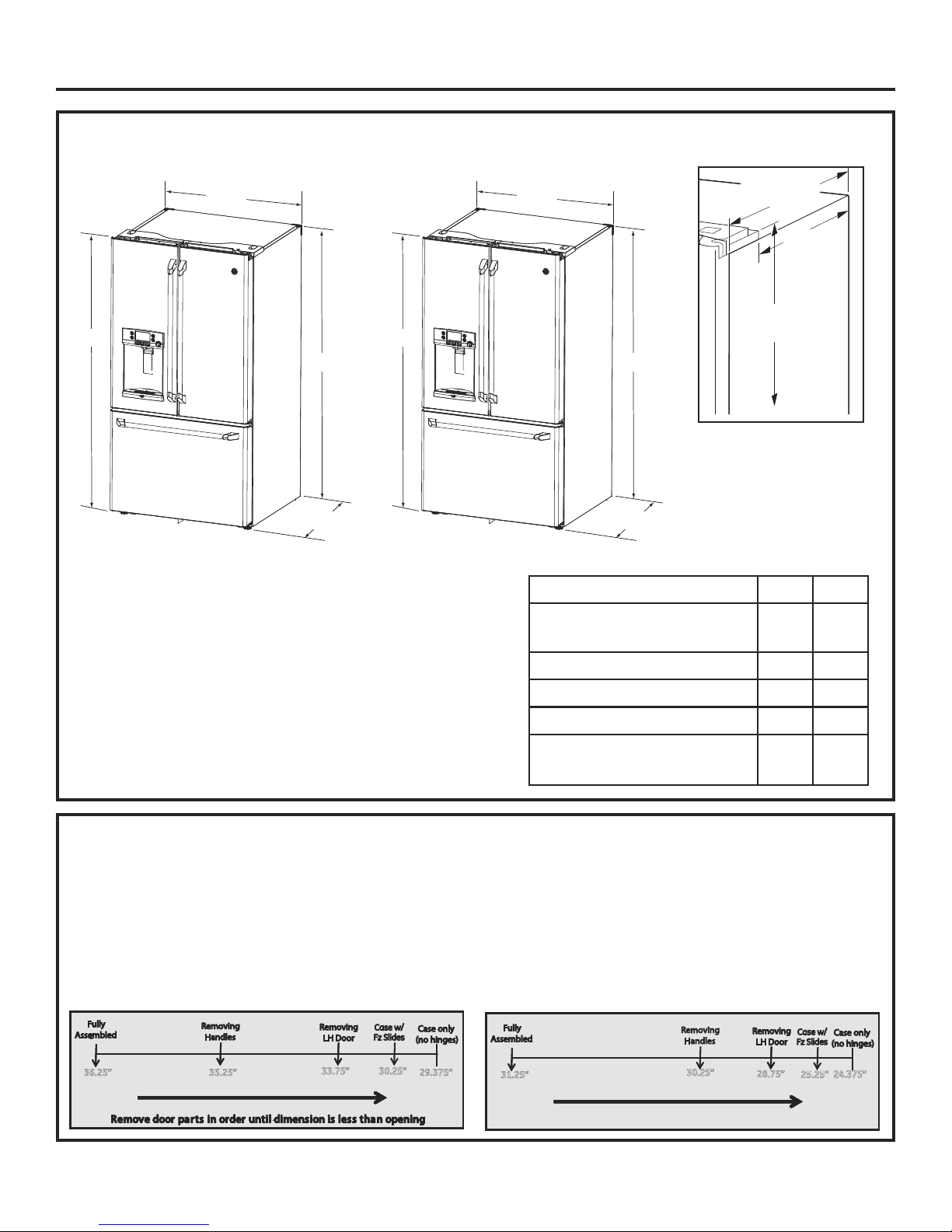
DIMENSIONS
7
ø8
”
All measurements are given with leveling leg fully retracted.
CFE OnlyCYE Only
353ø4”353ø4”
7
ø8
69
”69
Case Depth w/o
Doors 29 3ø8
Height from
floor to hinge
cover top 69
69”69”
Additional Dimensions
361ø4”311ø4”
”
231ø4” CFE
181ø4” CYE
7
ø8”
MOVING THE REFRIGERATOR
8VLQJWKHFKDUWEHORZGHWHUPLQHLIWKHZLGWKRI\RXUSDVVDJHZD\FDQDFFRPPRGDWHWKHGHSWKRIWKHUHIULJHUDWRU
Ensure you have clearance to prevent damage to the refrigerator before safety moving it to the final location.
,ISDVVDJHZD\VDUHODUJHHQRXJKWRDFFRPPRGDWHWKHUHIULJHUDWRUZLWKRXWUHPRYLQJWKHKDQGOHVVNLSWR6WHS/HDYH
tape, film and all packaging on doors until the refrigerator is in the final location.
NOTE: Use a padded hand truck or moving straps to move this refrigerator. Place the refrigerator on the hand truck
with a side against the truck. We strongly recommend that two people move and complete this installation.
If your model number starts with CFE
Overall Height to Top of
Hinge Cover
Height to Top of Cabinet
Case Depth without Doors
Overall Exterior Case Width
Overall Exterior Depth
Doors/Drawers with Handles
If your model number starts with CYE
CFE CYE
69
7
ø8
7
”69
ø8
69” 69”
29
3
ø8
3
”24
353ø4”353ø4”
36¼” 31¼”
”
ø8
36.25” 35.25” 29.375”
33.75” 30.25”
22
31.25”
30.25”
28.75”
25.25”
24.375”
Page 3

Installation Instructions
INSTALLING THE REFRIGERATOR
REFRIGERATOR LOCATION
'RQRWLQVWDOOWKHUHIULJHUDWRUZKHUHWKHWHPSHUDWXUHZLOO
go below 60°F (16°C) because it will not run often enough
to maintain proper temperatures.
'RQRWLQVWDOOWKHUHIULJHUDWRUZKHUHWKHWHPSHUDWXUHZLOO
go above 100°F (37°C) because it will not perform properly.
,QVWDOOLWRQDIORRUVWURQJHQRXJKWRVXSSRUWLWIXOO\ORDGHG
REMOVE THE FRESH FOOD
1
DOOR HANDLE
Handle Design varies based on models, however
Installation is same.
Stainless steel and plastic handles:
Loosen the set screws with the 1/8” Allen wrench and
remove the handle.
NOTE: If the handle mounting fasteners need to be tightened or
removed, use a 1/4” Allen wrench.
CLEARANCES
Allow the following clearances for ease of installation, proper
air circulation and plumbing and electrical connections.
Sides 1/8” (3 mm)
Top 1” (25 mm) Cabinet/Hinge Cover
Back 2” (50 mm)
REMOVING THE REFRIGERATOR DOORS
IMPORTANT NOTE: This refrigerator is 361/4” deep (311/4”
for CYE models). Doors and passageways leading to the
installation location must be at least 36
leave the doors and handles attached to the refrigerator
while transporting it into the installation location. If
passageways are less than 36
1
/4”, the refrigerator doors and
handles can easily be scratched and damaged. The top cap
and doors can be removed to allow the refrigerator to be
safely moved indoors. If passageways are less than 31
start with Step 1.
,ILWLVQRWQHFHVVDU\WRUHPRYHGRRUVVNLSWR6WHS/HDYH
tape and all packaging on doors until the refrigerator is in the
final location.
NOTE: Use a padded hand truck to move this refrigerator.
Place the refrigerator on the hand truck with a side against
the truck. We strongly recommend that TWO PEOPLE move
and complete this installation.
1
/4” wide in order to
1
/4”,
Mounting
Fasteners
Leave film
on until after
installation
REMOVE THE FREEZER DOOR HANDLE
2
Handle Design varies based on models, however
Installation is same.
Stainless steel and plastic handles:
Loosen the set screws with the 1/8” Allen wrench and remove the
handle.
NOTE: If the handle mounting fasteners need to be tightened or
removed, use a 1/4” Allen wrench.
Mounting
Fasteners
Leave film
on until after
installation
Reinstall the handles using the same
procedure as removing.
23
Page 4
Installation Instructions
INSTALLING THE REFRIGERATOR (cont.)
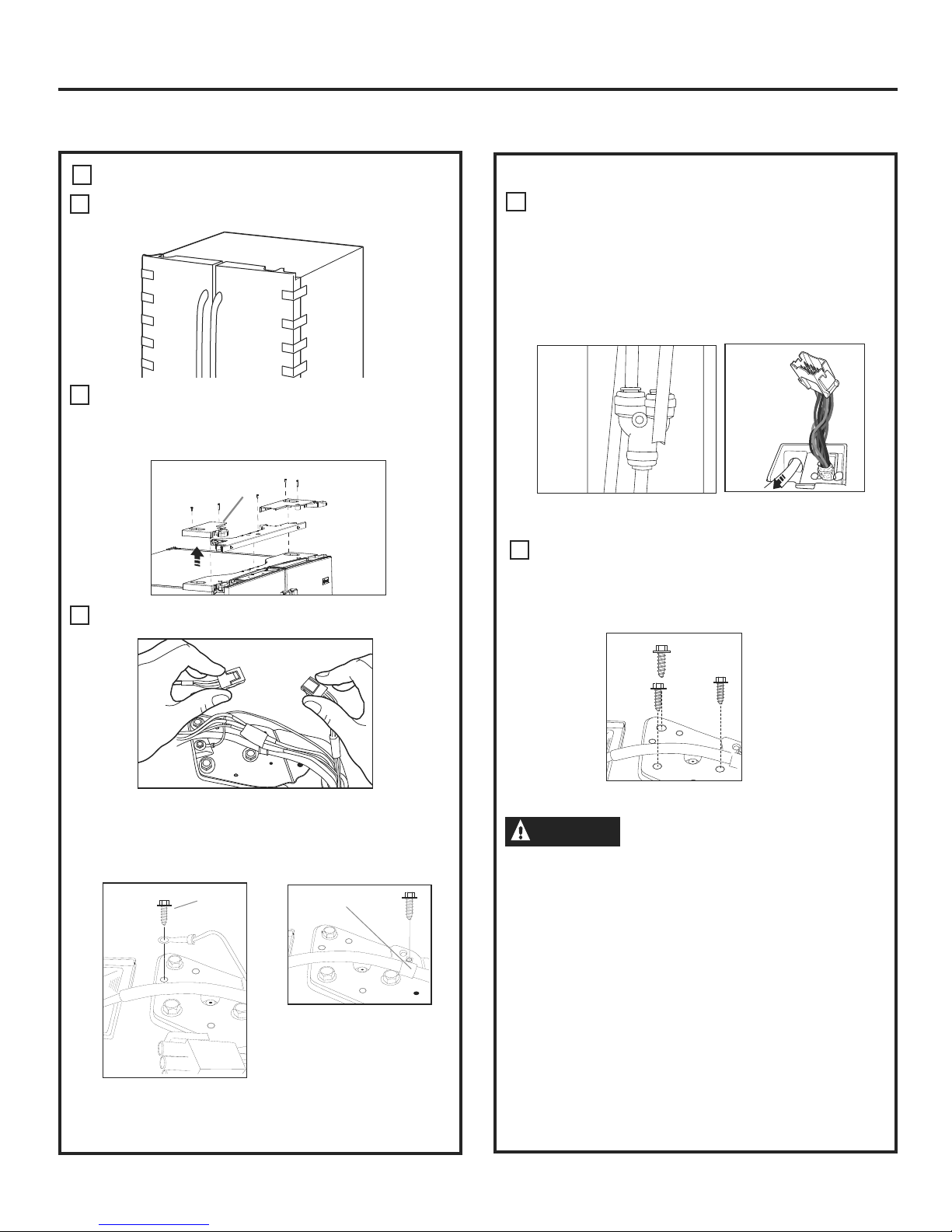
REMOVE THE REFRIGERATOR DOORS
3
Securely tape the door shut with masking tape or have
A
a second person support the door.
Start with left-hand door first: Remove the hinge cover
B
on top of the left refrigerator door by removing all hex
screws and pulling it up. Do the same for the
right-hand door and the middle cover.
Hinge
Cover
REMOVE THE REFRIGERATOR DOORS (cont)
D
Disconnect the water line from the back of the unit by
pressing down on the dark grey collar while pulling up
on the water line.
Pull waterline through case conduit from the top to free
the line for door removal. The water line is more than 4’
long and may need to be taped to Door for accessibility
when reinstalling.
C
Disconnect both electrical connectors at the top cover.
Remove the 1/4” hex head screw to disconnect the
ground wire from the hinge.
Remove the 1/4” hex head screw to remove the strain
relief from the water line.
Ground
screw
Strain
Relief
Using a 3/8” socket ratchet/driver, remove the screws
E
securing the top hinge to the cabinet,
then lift the hinge straight up to free the hinge pin from
the location in the top of the door.
CAUTION
Single person lift could cause injury. Use assistance
when handling, moving or lifting the refrigerator doors.
Note: when removing door, to prevent damage to door
and electronics, carefully place the door in a proper
location.
Note: The lower door hinge pin and hinge are keyed and
must be matched correctly for the door to self close
properly. Please follow the directions carefully.
Lifting Hazard.
24
Page 5

Installation Instructions
INSTALLING THE REFRIGERATOR (cont.)
REMOVE THE REFRIGERATOR DOORS (cont)
Note: for proper installation later, please follow the next step
carefully.
Fresh Food doors to be REMOVED and INSTALLED
F
opened at 90 with case front.
Lift up & off
center hinge
Open Door
to 90°
REMOVE OPPOSITE DOOR
Follow the same procedure on the opposite
door. There are no wires or water lines on the opposite
side
4
REMOVE CENTER HINGE (if necessary)
Remove the 3/8ļscrews securing the center hinge to the cabinet.
Use T20 driver to remove outboard screw
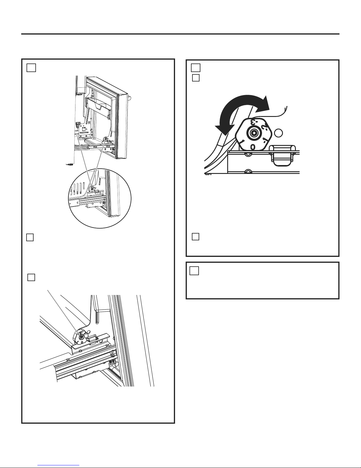
REINSTALLING THE REFRIGERATOR DOORS
5
Reverse steps 1 through 4 to reinstall refrigerator, follow
details below for critical alignments.
A
Reinstall center hinge first and torque the screws to
65 in-lbs. With the LH door at 90º to the front of
the case, lower the refrigerator door onto the center
hinge. Ensure that the door and hinge align correctly.
B
Rotate doors closed and make sure moveable center
sealing portion of the door aligns with the striker. If the
door will not self-close after reinstalling, remove door,
turn door upside down, check alignment mark and
arrow; (there is an alignment mark on the door closure
mechanism It corresponds to an alignment mark on
the bottom end cap. Rotate door closure mechanism to
align mark and arrow, reinstall door).
Underside OF
Fresh Food Door
Remove
center
screw
Loosen Outer screws
25
align marks
If door cannot be installed at 90° follow steps below:
1. If space or model limits opening door to less than 180°, then:
a) Remove door, carefully turn door upside down.
b) Check alignment of door closure mechanism shaft on
underside of door. The flats on the shaft should
correspond to alignment tab on plastic ring or mark
on bottom end cap.
c) If shaft is not aligned to tab/mark, using 5/32” Allen
wrench, rotate door closure mechanism shaft
counterclockwise for right door and clockwise for left
door. Then align flat with tab/mark.
d) Install the door at 90°.
Securely tape the door shut with masking tape or
have a second person support the door. Reinstall the
top hinge and torque the screws to 65 in-lbs.
Be sure to reinstall the ground wire and strain relief to
C
the top hinge.
Reinstall the hinge cover. Note: Ensure wires are not
D
pinched or under screw bosses before tightening screws.
Page 6
Installation Instructions
INSTALLING THE REFRIGERATOR (cont.)
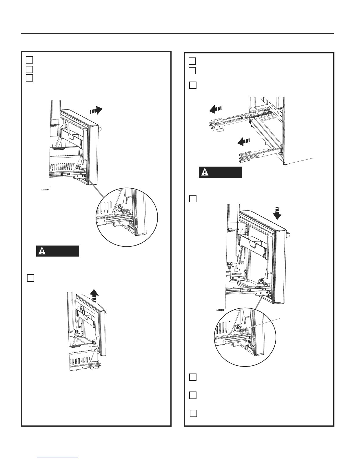
REMOVE THE FREEZER DOOR
6
A
Pull the freezer door open to full extension.
Remove 3 attachment screws, located at the bottom
B
on each side of the freezer door using 3/8” hex socket
driver.
7
A
B
REPLACING THE FREEZER DOOR
Pull the slide Mechanism to full extension using both
hands simultaneously.
Remove the basket resting on the slides.
CAUTION
Freezer door is heavy Use both hands to secure the
door before lifting.
Lift the freezer door to disengage it from the slide
C
mechanism
Lifting Hazard
CAUTION
Freezer door is heavy Use both hands to secure the
door before lifting.
Lift the freezer door and place it on the slide mechanism
C
Lifting Hazard
Align and insert
tab on freezer
door bracket
into slot on
freezer slide
bracket.
The door can safely rest on the bottom. Do not rest the
door on any other surfaces to avoid scratches.
Push the slide mechanism back completely until it self
retracts.
26
Replace the attachment screws and torque the screws
D
to 65 in-lb
For adjusting freezer door gaps, follow the instructions
E
on pg 27.
Replace the basket
F
Page 7
Installation Instructions
INSTALLING THE REFRIGERATOR (cont.)
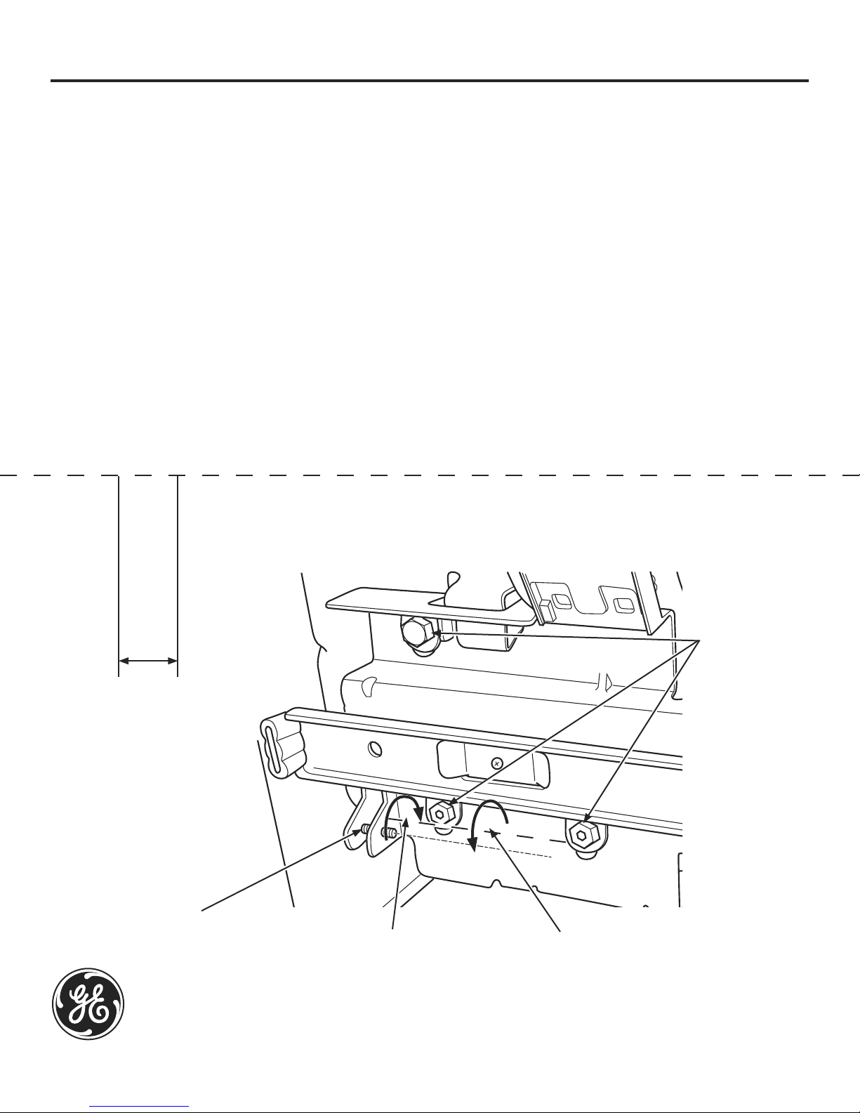
Instructions for adjusting freezer door gaps:
IMPORTANT!
The 6 mounting screws (3 on each side) are NOT interchangeable with the center or top hinge
screws. Drawer screws have flat washer heads, and other screws have lines/ribs on washer heads.
After installation of the freezer door, check for uniform gaps (top and bottom of right and left hand side)
with the template provided.
In the event of excessive gaps use the following steps to adjust the freezer door.
Step 1 - Loosen the 3 screws on each side (right and left) of the freezer door.
Step 2 - Adjust set screw clockwise if gap at the top is too big (see template). Turn the set screw using 3/32” hex
key clockwise by quarter to half a rotation
Step 3 - Adjust set screw counter-clockwise if gap at the bottom is too big (see template). Turn the set screw
using 3/32” hex key counter-clockwise by quarter to half a rotation
Step 4 - Tighten the 3 screws on each side (right and left).
Step 5 - Re-check the gaps using the template and repeat steps 1 to 4 if required and complete with step 5.
Fold here for using template
0.600”
Template for checking gaps.
Gap should be 0.6” or below.
Gabarit pour vérifier les
écarts. L’écart doit être de
0,6 po (1,5 cm) ou moins.
Plantilla para el control de
espacios. El espacio debería
ser de 0.6” o inferior.
Plier ici pour utiliser le gabarit Dóblelo aquí para usar la plantilla
Step 1
Étape 1
Paso 1
Step 4
Étape 4
Paso 4
Set Screw
Vis d’ajustement
Tornillo del Set
GE Appliances
General Electric Company
Louisville, KY 40225
GEAppliances.com
Step 2
Étape 2
Paso 2
Step 3
Étape 3
Paso 3
Refer to 239D4144P001 Pub No. 31-45474-2 11-12 GE
27
Page 8
Installation Instructions
INSTALLING THE REFRIGERATOR (cont.)
LEVEL THE FREEZER DOOR
8
9
LEVEL THE FREEZER DOOR (cont.)
A
Lift the door on the side requiring adjustment,
rotate the cam to required position.
0 - Initial position
1 - Lift by 0.050”
-1 - Lower by 0.050”
-2 - Lower by 0.100
-3 - Lower by 0.150”
Locate the height adjuster cam in the freezer
A
door. Slightly loosen the three door attachment
screws on both sides using a 3/8” hex socket
driver.
Locate and loosen the cam screw using the
B
T-27 screw driver.
After adjustment tighten the 3 attachment
B
screws using to 65 in-lb.
REMOVE PACKAGING
10
A) Remove all tape, foam and protective
packing from shelves and drawers.
28
Page 9

Installation Instructions
INSTALLING THE REFRIGERATOR (cont.)
Anti-Tip Floor Bracket Installation (Models PYE, CYE, and PWE only)
WARNING
Tip Over Hazard.
Built-in style models (model PYE, CYE, and PWE) are
top heavy, especially with any doors open. These
models must be secured with the anti-tip floor
bracket to prevent tipping forward, which could
result in death or serious injury. Read and follow
the entire installation instructions for installing the
anti-tip floor bracket packed with your refrigerator.
NOTE:
If you did not receive an anti-tip bracket with your
purchase, call 1.800.626.8774 to receive one at no
cost. (In Canada, call 1.800.561.3344.)
For installation instructions of the bracket, visit:
www.GEAppliances.com.
(In Canada, www.GEAppliances.ca.)
MATERIALS YOU MAY NEED (not included)
TOOLS YOU WILL NEED
1/8” (3 mm) Drill Bit and
Electric or Hand Drill
Pencil
Tape measure
5/16” (8 mm) Nut Driver
LOCATING THE ANTI-TIP FLOOR
AT-2
BRACKET
Place the anti-tip floor bracket locator template
A
(included inside the anti-tip kit) onto the floor up
against the rear wall, within W, and in line with the
desired location of the RH side of the refrigerator
(see Figure 1).
Figure 1 – Installation Overview
Floor – Concrete
(2 Holes)
Floor – Wood
(2 Holes)
2 Wall Holes
Floor Bracket
to Install
RH Holes
Lag Bolts
1/4” (6 mm) x 1-1/2” (38 mm)
Drill Bit Appropriate for Anchors
For Anti-Tip Bracket Mounted on CONCRETE Floors Only
Anchor Sleeves
1/2” (12 mm) OD
MEASURE CABINET OPENING
AT-1
AVAILABLE VS. REFRIGERATOR WIDTH
Measure width of cabinet opening where refrigerator
will be placed, W.
Be sure to account for any countertop overhang,
baseboard thickness and any clearance desired. Width,
W, should not be less than 36”. The refrigerator will be
placed approximately in the middle of this opening.
Rear Wall
W
REFRIGERATOR
Front
Baseboard
Thickness or
Countertop
Overhang
(Whichever Is
Larger) Plus
Any Desired
Clearance
RH Side
29
15 ¼”
Rear RH
Corner of
Base Bracket
on the
Refrigerator
Place the anti-tip floor bracket onto the locator
B
RH Side of
Refrigerator
Cabinet Wall
Locator Template
Sheet
template with its RH floor holes lined up with
the floor holes indicated on the template sheet,
approximately 15 ¼” from the edge of the sheet or
the RH side of the refrigerator.
Hold down in position and use the anti-tip floor
C
bracket as a template for marking the holes based
upon your configuration and type of construction
as shown in Step 3. Mark the hole locations with a
pencil, nail or awl.
NOTE:
It is REQUIRED to use at least 2 screws to mount
the floor bracket (one on each side of the anti-tip
floor bracket). Both must be into either the wall
or the floor. Figure 2 indicates all the acceptable
mounting configurations for screws. Identify the
screw holes on the anti-tip floor bracket for your
configuration.
Refer tp 239D1142 P001 Pub# 31-45484-2
Page 10

Installation Instructions
INSTALLING THE REFRIGERATOR (cont.)
Anti-Tip Floor Bracket Installation (Models PYE, CYE, and PWE only) (cont.)
LOCATING THE ANTI-TIP FLOOR
AT-2
BRACKET (cont.)
Figure 2 – Acceptable Screw
Placement Locations
Recommended Installation
Minimum Acceptable #1 –
AT-3
A
– Wood
Wall Plate Stud
Minimum Acceptable #3 –
Concrete Floor
ANTI-TIP BRACKET INSTALLATION
WOOD Wall and Floor Construction:
'ULOOWKHDSSURSULDWHQXPEHURIµPP
pilot holes in the center of each floor bracket
hole being used (a nail or awl may be used
if a drill is not available) AND remove the
locator template from the floor.
Mount the anti-tip floor bracket by fastening the
2, or recommended 4, #10-16 hex-head screws
tightly into place as illustrated in Figure 3.
Recommended Installation
– Concrete
Minimum Acceptable #2 –
Wood Floor
Figure 3 – Attachment to Wall and Floor
Rear RH
Corner of the
Refrigerator
2 Screws
Must Enter
Wood or
Metal Stud
Floor
Floor
Bracket
Wall
Wall
Plate
Stud
CONCRETE Wall and Floor Construction:
B
$QFKRUVUHTXLUHGQRWSURYLGHG
4 each 1/4” (6 mm) x 1-1/2” (38 mm) lag bolts
4 each 1/2” (12 mm) O.D. sleeve anchors
'ULOOWKHUHFRPPHQGHGVL]HKROHVIRUWKH
anchors into the concrete at the center of the
holes marked in Step 2.
,QVWDOOWKHVOHHYHDQFKRUVLQWRWKHGULOOHG
holes. Place the anti-tip floor bracket as
indicated in Step 2. Remove the locator
template from the floor.
,QVWDOOWKHODJEROWVWKURXJKWKHDQWLWLSIORRU
bracket and tighten appropriately.
WOOD Wall and TILE Floor Construction:
C
)RUWKLVVSHFLDOFDVHORFDWHWKHZDOOKROHV
identified in Fig. 1. Drill an angled 1/8” (3 mm)
pilot hole (approx. as shown in Fig. 3) in the
center of each hole.
0RXQWWKHDQWLWLSIORRUEUDFNHWXVLQJWKH
Minimum Acceptable Installation #1, as
illustrated in Fig. 2.
AT-4
POSITIONING THE REFRIGERATOR
TO ENGAGE THE ANTI-TIP FLOOR
AND BASE BRACKETS
Before pushing the refrigerator into the
opening, plug the power cord into the
A
receptacle and connect waterline (if equipped).
Check for leaks.
Locate the refrigerator’s RH side and move back
approximately in line with the RH side of the
B
cabinet opening, W. This should position the
anti-tip floor bracket to engage the anti-tip base
bracket on the refrigerator.
Gently roll the refrigerator back into the cabinet
opening until it comes to a complete stop. Check to
C
see if the refrigerator front lines up with the cabinet
front face. If not, carefully rock the refrigerator
forward and backward until engagement occurs
and you notice that the refrigerator is fully pushed
up against the rear wall.
If Applicable: Adjust the rear (and front) wheel
height settings to fully engage the rear anti-tip
brackets, while also aligning the refrigerator
D
front with the cabinet front face.
NOTE:
If you pull the refrigerator out and away from the wall for
any reason, make sure the anti-tip floor bracket is engaged
when the refrigerator is pushed back against the rear wall.
30
Refer tp 239D1142 P001 Pub# 31-45484-2
Page 11

Installation Instructions
INSTALLING THE REFRIGERATOR (cont.)
11
CONNECTING THE REFRIGERATOR
TO THE HOUSE WATER LINE
A cold water supply is required for automatic ice maker
operation. If there is not a cold water supply, you will
need to provide one. See Installing the Water Line section.
NOTES:
%HIRUHPDNLQJWKHFRQQHFWLRQWRWKHUHIULJHUDWRUEH
sure the refrigerator power cord is not plugged into the
wall outlet.
,I\RXUUHIULJHUDWRUGRHVQRWKDYHDZDWHUILOWHUZH
recommend installing one if your water supply has
sand or particles that could clog the screen of the
refrigerator’s water valve. Install it in the water line
near the refrigerator. If using GE SmartConnect
Refrigerator Tubing Kit, you will need an additional tube
(WX08X10002) to connect the filter. Do not cut plastic
tube to install filter.
%HIRUHFRQQHFWLQJWKHZDWHUOLQHWRWKHKRXVHSXUJH
the house line for at least 2 minutes.
A
If you are using copper tubing, place a compression nut
and ferrule (sleeve) onto the end of the tubing coming
from the house cold water supply.
™
If you are using the GE SmartConnect
tubing, the nuts
are already assembled to the tubing.
™
If you are using copper tubing, insert the end of the
B
tubing into the refrigerator connection, at the back of the
refrigerator, as far as possible. While holding the tubing,
tighten the fitting.
™
If you are using GE SmartConnect
tubing, insert
the molded end of the tubing into the refrigerator
connection, at the back of the refrigerator, and tighten
the compression nut until it is hand tight. Then tighten
one additional turn with a wrench. Over tightening may
cause leaks.
Fasten the tubing into the clamp provided to hold it in
C
position. You may need to pry open the clamp.
1/4” Compression
Nut
Ferrule
(sleeve)
Tubing Clamp
Bride
Abrazadera del tubo
1/4“ Tubing
Tuyau de 1/4 po
Tubería de 1/4“
SmartConnect
Tubing
Refrigerator
Connection
™
31
Page 12

Installation Instructions
INSTALLING THE REFRIGERATOR (cont.)
TURN ON THE WATER SUPPLY
12
Turn the water on at the shutoff valve (house water
supply) and check for any leaks.
PLUG IN THE REFRIGERATOR
13
See the grounding information attached to the power
cord.
LEVEL THE REFRIGERATOR
14
The leveling legs have 2 purposes:
1) Leveling legs adjust so the refrigerator is
firmly positioned on the floor and does not
wobble.
2) Leveling legs serve as a stabilizing brake
to hold the refrigerator securely in position
during operation and cleaning. The leveling
legs also prevent the refrigerator from
tipping.
15
LEVEL THE REFRIGERATOR DOORS
Remember a level refrigerator is necessary for
getting the doors perfectly even. If you need
help, review the previous section on leveling the
refrigerator.
When
the left
door is
lower than
the right
door.
If you open the freezer door, you can see
A
When
the left
door is
higher
than
the right
door.
Adjustment
point
the center hinge.
Insert 1/4” Allen wrench into the shaft of the
B
center hinge.
Adjust the height by turning clockwise
C
or counterclockwise. When you turn
counterclockwise, the door will move up.
RAISE
Turn the leveling legs clockwise to raise
A
the refrigerator, counterclockwise to lower it.
Flat-Head Screwdriver
NOTICE: To avoid possible property
damage, the leveling legs must be firmly
touching the floor.
Raise
32
Page 13

Installation Instructions
INSTALLING THE REFRIGERATOR (cont.)
Refrigerator Assembly Instructions, suggested assembly.
G
G
To place bins into doors:
Match your bin with the letter shown.
Position the bin hooks over the
bin locator and push forward until
inserted fully.
Push bin down until locked into
position.
Bin locator
each side
G
Divider
(Select
models only)
Bin hook
rear each side
Refer to 239D4129P002 Pub# 31-45498
33
Page 14

Installation Instructions
INSTALLING THE WATER LINE
BEFORE YOU BEGIN
Recommended copper water supply kits are WX8X2,
WX8X3 or WX8X4, depending on the amount of tubing
you need. Approved plastic water supply lines are GE
SmartConnect
WX08X10015 and WX08X10025).
When connecting your refrigerator to a GE Reverse
Osmosis Water System, the only approved installation
is with a GE RVKit. For other reverse osmosis water
systems, follow the manufacturer’s recommendations.
If the water supply to the refrigerator is from a
Reverse Osmosis Water Filtration System (RO)
AND the refrigerator also has a water filter,
use the refrigerator’s filter bypass plug. Using
the refrigerator’s water filtration cartridge in
conjunction with an RO water filter can result in
hollow ice cubes.
This water line installation is not warranted by the
refrigerator or ice maker manufacturer. Follow
these instructions carefully to minimize the risk of
expensive water damage.
Water hammer (water banging in the pipes) in
house plumbing can cause damage to refrigerator
parts and lead to water leakage or flooding. Call a
qualified plumber to correct water hammer before
installing the water supply line to the refrigerator.
To prevent burns and product damage, do not hook
up the water line to the hot water line.
For LCD Models: If the refrigerator is operated
before the water connection is made to the ice
maker, see ICE MAKER under “settings” menu of
the LCD Operations section and follow the screen
commands to turn the ice maker OFF.
Do not install the ice maker tubing in areas where
temperatures fall below freezing.
When using any electrical device (such as a power
drill) during installation, be sure the device is double
insulated or grounded in a manner to prevent the
hazard of electric shock, or is battery powered.
All installations must be in accordance with local
plumbing code requirements.
™
Refrigerator Tubing (WX08X10006,
WHAT YOU WILL NEED
&RSSHURU*(6PDUW&RQQHFW™ Refrigerator Tubing
kit, 1/4” outer diameter to connect
the refrigerator to the water supply. If using
copper, be sure both ends of the tubing are
cut square.
To determine how much tubing you need:
measure the distance from the water valve
on the back of the refrigerator to the water supply
pipe. Be sure there is sufficient extra tubing to allow
the refrigerator to move out from the wall after
installation.
™
GE SmartConnect
available in the following lengths:
6’ (1.8 m) – WX08X10006
15’ (4.6 m) – WX08X10015
25’ (7.6 m) – WX08X10025
Refrigerator Tubing Kits are
34
Page 15

Installation Instructions
INSTALLING THE WATER LINE (cont.)
WHAT YOU WILL NEED (CONT.)
NOTE: The only GE approved plastic tubing
is that supplied in GE SmartConnect
Tubing kits. Do not use any other plastic water
supply line because the line is under pressure at all
times. Certain types of plastic will crack or rupture
with age and cause water damage to your home.
$*(ZDWHUVXSSO\NLW FRQWDLQLQJWXELQJ
shutoff valve and fittings listed below) is available
at extra cost from your dealer or from Parts
and Accessories, 800.626.2002 (in Canada
1.800.661.1616).
$FROGZDWHUVXSSO\ 7KHZDWHUSUHVVXUHPXVWEH
between 20 and 120 p.s.i. (1.4–8.1 bar).
3RZHUGULOO
1/2” or adjustable wrench.
6WUDLJKWDQG3KLOOLSVEODGHVFUHZGULYHU
™
Refrigerator
Install the shutoff valve on the nearest frequently
used drinking water line.
1
SHUT OFF THE MAIN WATER SUPPLY
Turn on the nearest faucet long enough to clear
the line of water.
2
CHOOSE THE VALVE LOCATION
Choose a location for the valve that is easily
accessible. It is best to connect into the side
of a vertical water pipe. When it is necessary
to connect into a horizontal water pipe, make
the connection to the top or side, rather than at
the bottom, to avoid drawing off any sediment
from the water pipe.
7ZR ” outer diameter compression nuts
DQGIHUUXOHVVOHHYHV³WRFRQQHFWWKHFRSSHU
tubing to the shutoff valve and the refrigerator
water valve.
OR
,I\RXDUHXVLQJD*(6PDUW&RQQHFW
Refrigerator Tubing kit, the necessary fittings
are preassembled to the tubing.
,I\RXUH[LVWLQJFRSSHUZDWHUOLQHKDVDIODUHG
fitting at the end, you will need an adapter
(available at plumbing supply stores) to connect
the water line to the refrigerator OR you can cut
off the flared fitting with a tube cutter and then
use a compression fitting. Do not cut formed end
from GE SmartConnect
6KXWRIIYDOYHWRFRQQHFWWRWKHFROGZDWHUOLQH
The shutoff valve should have a water inlet with
a minimum inside diameter of 5/32” at the point of
connection to the COLD WATER LINE. Saddle-type
shutoff valves are included in many water supply
kits. Before purchasing, make sure a saddle-type
valve complies with your local plumbing codes.
™
Refrigerator tubing.
™
DRILL THE HOLE FOR THE VALVE
3
Drill a 1/4” hole in the water pipe (even if using
a self-piercing valve), using a sharp bit. Remove
any burrs resulting from drilling the hole in
the pipe.
Take care not to allow water to drain into
the drill.
Failure to drill a 1/4” hole may result in reduced
ice production or smaller cubes.
35
Page 16

Installation Instructions
INSTALLING THE WATER LINE (cont.)
4
FASTEN THE SHUTOFF VALVE
Fasten the shutoff valve to the cold water pipe
with the pipe clamp.
Pipe Clamp
Saddle-Type
Shutoff Valve
Vertical Cold
Water Pipe
NOTE: Commonwealth of Massachusetts
Plumbing Codes 248CMR shall be adhered to.
Saddle valves are illegal and use is not permitted
in Massachusetts. Consult with your licensed
plumber.
TIGHTEN THE PIPE CLAMP
5
Tighten the clamp screws until the sealing
washer begins to swell.
NOTE: Do not over tighten or you may crush
the tubing.
Washer
Pipe Clamp
Inlet End
7
CONNECT THE TUBING TO THE VALVE
Place the compression nut and ferrule (sleeve)
for copper tubing onto the end of the tubing
and connect it to the shutoff valve.
Make sure the tubing is fully inserted into
the valve. Tighten the compression nut securely.
For plastic tubing from a GE SmartConnect
Refrigerator Tubing kit, insert the molded end
of the tubing into the shutoff valve and tighten
compression nut until it is hand tight, then
tighten one additional turn with a wrench. Over
tightening may cause leaks.
Saddle-Type
Shutoff Valve
Packing Nut
Outlet Valve
Ferrule (sleeve)
Compression Nut
SmartConnect
Tubing
NOTE: Commonwealth of Massachusetts
Plumbing Codes 248CMR shall be adhered to.
Saddle valves are illegal and use is not permitted
in Massachusetts. Consult with your licensed
plumber.
™
™
Clamp
Screw
ROUTE THE TUBING
6
Route the tubing between the cold water line
and the refrigerator.
Route the tubing through a hole drilled in the
wall or floor (behind the refrigerator or adjacent
base cabinet) as close to the wall as possible.
8
FLUSH OUT THE TUBING
Turn the main water supply on and flush out
the tubing until the water is clear.
Shut the water off at the water valve after about
one quart (1 liter), or 2 minutes, of water has
been flushed through the tubing.
To complete the installation of the refrigerator, go back
to Step 11 in Installing the Refrigerator.
36
Page 17

Normal operating conditions.
Newer refrigerators sound different from older refrigerators.
Modern refrigerators have more features and use newer technology.
Do you hear what I hear? These sounds are normal.
HUMMM...
WHOOSH...
The new high efficiency compressor may run faster and longer
than your old refrigerator and you may hear a high-pitched hum
or pulsating sound while it is operating.
You may hear a whooshing sound when the doors close. This is
due to pressure equalizing within the refrigerator.
After dispensing ice, a motor will close the ice chute to keep
warn room air from entering the ice bucket, maintaining ice at a
freezing temperature.
The hum of the motor closing the ice chute is normal, shortly after
dispensing ice.
You may hear the fans spinning at high speeds. This happens
when the refrigerator is first plugged in, when the doors are
opened frequently or when a large amount of food is added to
the refrigerator or freezer compartments. The fans are helping to
maintain the correct temperatures.
The fans change speeds in order to provide optimal cooling and
energy savings.
CLICKS, POPS,
CRACKS and SNAPS
You may hear cracking or popping sounds when the refrigerator
is first plugged in. This happens as the refrigerator cools to the
correct temperature.
Expansion and contraction of cooling coils during and after
defrost can cause a cracking or popping sound.
On models with an ice maker, after an ice making cycle, you may
hear the ice cubes dropping into the ice bucket.
On models with a dispenser, during water dispense, you may
hear the water lines move at initial dispense and after dispenser
button is released.
START UP COOLING
It can take up to 24 hours for the refrigerator and freezer
temperatures to match the display. During that time refrigerator and
freezer door openings should be minimized.
TIPS
Freezer cools first.
Refrigerator compartment cools last; it may take several
hours after the freezer.
Turning off ice maker makes both fresh food and freezer
food cool faster.
WATER SOUNDS
The flow of refrigerant through the cooling coils may make a
gurgling noise like boiling water.
Water dropping on the defrost heater can cause a sizzling,
popping or buzzing sound during the defrost cycle.
A water dripping noise may occur during the defrost cycle as ice
melts from the evaporator and flows into the drain pan.
Closing the door may cause a gurgling sound due to pressure
equalization.
37
Page 18

Before you call for service…
Troubleshooting Tips
Save time and money! Review the charts on the following
pages first and you may not need to call for service.
Problem Possible Causes What to Do
Water filter indicator light
remains lit after replacing filter
Water filter indicator light is not lit This is normal. This indicator will turn
Handle is loose/handle has a gap. Handle needs adjusting See Attach Fresh Food Handle and
Refrigerator beeping This is door alarm Turn off or disable with door closed.
Not cooling The cooling system is off See About Controls.
Water has poor taste/odor Water dispenser has not been used
Water in glass is warm Normal when refrigerator is first
Water dispenser does not work Water supply line turned off or not
Water filter indicator must be reset On the LCD screen select
system SETTINGS, then WATER FILTER.
Select RESET.
See About the Water Filter for more
on to tell you that you need to replace
the filter soon.
for a long time
installed
Water dispenser has not been used
for a long time
Water system has drained Allow several hours for replenished
connected
Water filter clogged or filter/bypass
plug not installed
Air may be trapped in the water
system
information.
Attach the Freezer Handle sections for
detailed instructions.
If door open and alarm is sounding, you
can only snooze the alarm.
Dispense water, until all water in system
is replenished.
Wait 24 hours for the refrigerator to
completely cool down.
Dispense water, until all water in system
is replenished.
supply to chill.
See Installing the Water Line.
Replace filter cartridge or remove filter
and install bypass plug.
Press the dispenser arm for at least 5
minutes.
Water spurting from dispenser Newly installed filter cartridge Run cold water from the dispenser for
Water in reservoir is frozen because
the controls are set too cold
38
Set the refrigerator control to a warmer
setting and wait 24 hours. If the water
does not dispense after 24 hours, call for
service.
5 minutes (about 2 gallons)..
Page 19

GEAppliances.com
Troubleshooting Tips (cont)
Problem Possible Causes What to Do
No water or ice cube production Supply line or shutoff valve is clogged Call a plumber
Water filter is clogged Replace filter cartridge or remove filter and
install bypass plug
Filter cartridge not properly installed Remove and reinstall filter cartridge,
being certain that it locks in place.
Ice maker is turned off Check that the ice maker is turned on. See
About the Automatic Ice Maker.
Water is leaking from dispenser Air may be present in the water line
system, causing water to drip after
being dispensed
Photos not found Photos not in root directory of USB Make sure the photos are in the root direc-
Photos not in JPEG format Photos must be in JPEG format
Camera/PC used with USB cord Must use a USB drive
PRECISE FILL will not fill container Normal, PRECISE FILL requires use of
dispenser paddle
Freezer cooling, fresh food not cooling Normal, when refrigerator first
plugged in or after extended power
outage
Ice dispenser opens after closing
freezer drawer
Hot water does not work Operation disabled Make sure “Hot Water Disabled” is not
Hot water continues to dispense for a
short time after releasing the knob
Normal The ice dispenser door may open after
Low water pressure Make sure water line is not kinked
Water supply line turned off or not
connected
Water filter clogged or filter/bypass
plug not installed
Water filter is partially clogged or low
water pressure (<40 psi)
Dispense water for at least 5 minutes to
remove air from system
tory in your USB
For a specific amount of water, select PRE-
CISE FILL to dispense water
Wait 24 hours for temperature in both
compartments to reach selected
temperatures.
closing freezer door to allow access
selected
See Installing the Water Line
Replace filter cartridge or remove filter and
install bypass plug
Replace filter cartridge or remove filter
and install bypass plug or increase water
pressure
39
Page 20

Before you call for service, review the detailed troubleshooting tips in the Owner’s
SERVICE
manual. If needed, service can be scheduled by visiting us online GEAppliances.
com or calling 800.ge.CARES 800.432.2737
Truth or Myth
Truth or Myth? Answer Explanation
The refrigerator water filter may require replacement,
even though the filter indicator has not turned red, or
reads “Filter Expired.”
The automatic ice maker in my refrigerator will
produce ice when the refrigerator is plugged in to a
power receptacle.
After the refrigerator has been plugged in and
connected to water, I will immediately have unlimited
chilled water available from the water dispenser.
After water dispenses, a few drops of water are
normal.
I will never see frost inside the freezer compartment. MYTH Frost inside the freezer typically indicates that the door is not properly
When the refrigerator is installed, or after replacing the water filter, I must dispense water for five
minutes.
To fill the ice bucket to the maximum capacity, I
should dispense 12 and 18 hours after installation.
I can use the water filter bypass plug to determine if
the filter requires replacement.
The top of the refrigerator doors will always be
aligned.
Refrigerator door handles can be easily tightened. TRUE If door handles are loose or have a gap, the handle can be adjusted using
There may be odor and taste problems with your ice. TRUE After starting the ice maker throw away 24 hours of ice production to
I can make fine adjustments to the fresh food doors
to align them.
Door handles should always be removed for
installation.
TRUE The water filter indicator will indicate the need to replace the water filter
every six months. Water quality varies from city to city; if water flow from
the dispenser slows, or ice production decreases, the water filter should
be replaced, even though the filter indicator may not indicate the need for
replacement.
MYTH The refrigerator must be connected to water, and the ice maker must be
turned on. Make sure the ice maker is turned on, only after the water line
is connected and water is turned on. The ice maker can be turned on/
off from the controls and ensure the ice maker is on, as indicated on the
refrigerator control panel. See About the Automatic Ice Maker.
MYTH The water dispenser tank located inside the refrigerator stores water
for dispensing. The water in this tank requires 24 hours to chill after
installation. High usage conditions will not allow time for the water to
chill.
TRUE A few drops of water may fall from the dispenser, after the dispenser
paddle has been released. To minimize the drops, remove the glass
slowly from the dispenser.
sealed, or has been left open. If frost is found, clear the frost using a
plastic spatula and towel, then check to ensure that no food packages
or containers are preventing the freezer door from closing. Check the
refrigerator control panel to ensure the door alarm is on.
TRUE
TRUE Dispensing 3-4 cubes 12 hours and 18 hours after installation, allows ice
TRUE Decrease in flow from the water dispenser, or decreased ice production,
MYTH Several things can affect the fresh food door alignment, including the
TRUE If the fresh food doors are not aligned, use a 1/4” Allen wrench to adjust
MYTH Check chart on reverse side of this instruction. If the doors must be
A newly installed refrigerator or water filter contains air in the water lines.
Press the dispenser paddle and dispense cold water for at least 5 minutes
to remove air from the water line, and flush the filter.
to disperse within the ice bucket, which in turns calls on the ice maker to
produce additional ice. Normal ice production = 100 cubes in 24 hours.
may indicate the need to replace the water filter. Install the water filter
bypass plug (provided with the refrigerator), and check flow from the
dispenser. If water flow returns to normal with the bypass plug in place,
replace the water filter.
floor the refrigerator is installed on, and loading of doors. If the top of
the fresh food doors are not aligned, use a 1/4” allen wrench to adjust
the right hand door. The adjustment screw is located on the bottom right
hand side of the door; open the freezer door to access the screw. The left
hand fresh food door may be raised using spacers. Call 800-GECARES to
obtain the spacers.
a 1/8” allen wrench, on set screws located on the ends of the handles.
avoid odor and taste problems.
the right hand door. The adjustment screw is located on the bottom of the
right door. Open the freezer door to access. The left hand fresh food door
may be raised using spacers. Call 800-GECARES to obtain the spacers.
removed do not remove the handles, or if the refrigerator will fit easily
through the passage way opening. Adjust handles that are loose or have
a gap, by adjusting 1/8” set screws on either end of handles.
40
Page 21

Before you call for service, review the detailed troubleshooting tips in the Owner’s
SERVICE
manual. If needed, service can be scheduled by visiting us online GEAppliances.
com or calling 800.ge.CARES 800.432.2737
Truth or Myth (cont.)
Truth or Myth? Answer Explanation
Door removal is always required for installation. MYTH Check chart on reverse side of this instruction. Doors should only be
removed when necessary to prevent damage from passage way or
access to final location.
Refrigerator doors that won’t close after installation,
can be adjusted to close properly.
There is an adjustment to rear wheels. MYTH Front leveling legs are adjustable and should be used to balance the
Check for leaks after all water connections are made. TRUE While purging the air from the water system, check all water line
My LCD display will always be on when I plug the
power cord in at installation.
Any packaging residue can be cleaned off the
refrigerator using any cleaner.
TRUE Door mechanism works best if installed at 90°+. If installed at 180°,
remove the door from the mid hinge, and swing the door 180° before
reinstalling. See Reinstalling the Refrigerator Doors.
refrigerator. Leveling legs are used to make initial fresh food door
adjustment.
connections for leaks. Check the connection to the household water
supply at back of refrigerator, and door water line connect.
MYTH If the refrigerator has been stored in a cold environment, the LCD may be
slow to give a proper display. Give the refrigerator enough time to warm
up, and the display should be okay.
MYTH Do not use wax, polish, bleach, or other products containing chlorine on
Stainless Steel panels, door handles and trim. Check this instruction under
“Cleaning the Outside” for full details.
41
Page 22

Refrigerator Warranty. (For customers in the United States)
All warranty service provided by our Factory Service Centers, or
®
an authorized Customer Care
technician. To schedule service,
visit us online at GEAppliances.com, or call 800.GE.CARES
(800.432.2737). Please have serial number and model number
available when calling for service.
Staple your receipt here.
Proof of the original
purchase date is needed
to obtain service under the
warranty.
Servicing your refrigerator may require the use of the onboard data port for diagnostics. This gives a GE
Factory Service technician the ability to quickly diagnose any issues with your appliance and helps GE
improve its products by providing GE with information on your appliance. If you do not want your appliance
data to be sent to GE, please advise your technician NOT to submit the data to GE at the time of service.
For the Period of: GE Will Replace
GE PROFILE ™ AND
GE CAFÉ™ MODELS
One Year
From the date of the original
purchase
Thirty Days
(Water filter, if included)
From the original purchase
date of the refrigerator
GE PROFILE MODELS ONLY
Five Years
(GE Profile models only)
From the date of the
purchase
Any part of the refrigerator which fails due to a defect in materials or workmanship.
During the limited one-year warranty, GE will also provide, free of charge, all labor and related
service to replace the defective part.
Any part of the water filter cartridge which fails due to a defect in materials or workmanship. During
this limited thirty-day warranty, GE will also provide, free of charge, a replacement water filter
cartridge.
Any part of the sealed refrigerating system (the compressor, condenser, evaporator an all
connecting tubing) which fails due to a defect in materials or workmanship.
During this limited five-year sealed refrigerating system warranty, GE will also provide, free of
charge, all labor and related service to replace the defective part in the sealed refrigerating system.
What GE Will Not Cover:
■ Service trips to your home to teach you how to use the product.
■ Improper installation, delivery or maintenance.
■ Failure of the product if it is abused, misused, or used for other
than the intended purpose or used commercially.
■ Loss of food due to spoilage.
■ Replacement of house fuses or resetting of circuit breakers.
■ Damage caused after delivery.
■ Replacement of the water filter cartridge, if included, due to
water pressure that is outside the specified operating range or
due to excessive sediment in the water supply.
(;&/86,212),03/,(':$55$17,(6³<RXUVROHDQGH[FOXVLYHUHPHG\LVSURGXFWUHSDLUDVSURYLGHGLQWKLV
Limited Warranty. Any implied warranties, including the implied warranties of merchantability or fitness
for a particular purpose, are limited to one year or the shortest period allowed by law.
This warranty is extended to the original purchaser and any succeeding owner for products purchased for home
use within the USA. If the product is located in an area where service by a GE Authorized Servicer is not available,
you may be responsible for a trip charge or you may be required to bring the product to an Authorized GE Service
location for service. In Alaska, the warranty excludes the cost of shipping or service calls to your home.
Some states do not allow the exclusion or limitation of incidental or consequential damages. This warranty gives
you specific legal rights, and you may also have other rights which vary from state to state. To know what your
legal rights are, consult your local or state consumer affairs office or your state’s Attorney General.
■ Replacement of the light bulbs, if included, or water filter
cartridge, if included, other than as noted above.
■ Damage to the product caused by accident, fire, floods or acts
of God.
■ Incidental or consequential damage caused by possible defects
with this appliance.
■ Product not accessible to provide required service.
■ Damage caused by a non-GE Brand water filter.
Warrantor: General Electric Company. Louisville, KY 40225
42
Page 23

RPWF Water Filter Cartridge Limited Warranty.
Appliance Service
GE
Appliances
800-GE-CARES
For The Period Of: We Will Replace, At No Charge To You:
Contact us at www.geapplianceparts.com,
or call 800.GE.CARES.
Staple your receipt
here. Proof of the
original purchase
date is needed to
obtain service
under the warranty.
Thirty Days
From the date of the
Any part of the water filter cartridge which fails due to a defect in materials or
workmanship during this limited thirty-day warranty.*
original purchase
What is Not Covered:
? Service trips to your home to teach you how to use the product.
? Improper installation.
? Failure of the product if it is abused, misused, used for other than the intended
purpose or used commercially.
? Replacement of house fuses or resetting of circuit breakers.
? Replacement of the water filter cartridge due to water pressure that is outside the
specified operating range or due to excessive sediment in the water supply.
? Damage to the product caused by accident, fire, floods or acts of God.
? Incidental or consequential damage caused by possible defects with this appliance.
This warranty is extended to the original purchaser and any succeeding owner for products purchased for
home use within the U.S.A. In Alaska, the warranty excludes the cost of shipping or service calls to your home.
Some states do not allow the exclusion or limitation of incidental or consequential damages. This warranty
gives you specific legal rights, and you may also have other rights which vary from state to state. To know
what your legal rights are, consult your local or state consumer affairs office or your state’s Attorney General.
For Purchases Made In Iowa: This form must be signed and dated by the buyer and seller prior to the
consummation of this sale.
This form should be retained on file by the seller for a minimum of two years.
Buyer:
Name
Address
City State Zip
Signature Date
* If your GE part fails because of a manufacturing defect within thirty days from the date of original purchase for use, we will give you a new or, at our option, a rebuilt part without charge.
Return the defective part to the parts supplier from whom it was purchased together with a copy of the “proof of purchase” for the part. If the part is defective and shows no signs of abuse,
it will be exchanged. The warranty does not cover the failure of parts which are damaged while in your possession, are abused, or have been installed improperly. It does not cover the cost
of returning the part to the supplier from whom it was purchased nor does it cover the cost of labor to remove or install it to diagnose the fault. It does not cover parts used in products in
commercial use except in the case of air conditioning equipment. In no event shall GE be liable for consequential damages. Warrantor: General Electric Company
EXCLUSION OF IMPLIED WARRANTIES: Your sole and exclusive remedy is part exchange as provided in this Limited Warranty. Any implied warranties, including the implied warranties of
merchantability or fitness for a particular purpose, are limited to six months or the shortest period allowed by law.
GE
Appliances
Appliance Park
Louisville, KY 40225
geapplianceparts.com
Seller:
Name
Address
City State Zip
Signatur
43
eDate
© 2012 General Electric Company PC66596
Page 24

Performance Data Sheet
Model: GE RP
WF
Use Replacement Cartridge RPWF.
The concentration of the indicated substances in water entering the system was reduced to a concentration less than or equal to the permissible
limit for water leaving the system as specified in NSF/ANSI Standard 42 and Standard 53. System tested and certified by NSF International against
NSF/ANSI Standard 42 and Standard 53 for the reduction of substances listed below.
Capacity 170 Gallons (643.5 Liters). Contaminant Reduction Determined by NSF testing.
Substance Tested
for Reduction Average Infl uent
Chlorine Taste and Odor 2.0 mg/L 2.0 mg/L ± 10% 97.4% 0.05 mg/L N/A ≥50% J-00102044
Nominal Particulate
Class I, , ≥0.5 to < 1.0 μm 7,633,333 pts/mL At least 10,000 particles/mL 99.0% 71,850 pts/ml N/A ≥85% J-00106249
Asbestos 109 MFL
Atrazine 0.009 mg/L 0.009 mg/L ± 10% 94.4% 0.0005 mg/L 0.003 mg/L N/A J-00102058
Benzene 0.016 mg/L 0.015 mg/L ± 10% 96.4% 0.001 mg/L 0.005 mg/L N/A J-00102065
Carbofuran 0.08 mg/L 0.08 mg/L ± 10% 98.8% 0.001 mg/L 0.04 mg/L N/A J-00102059
Cyst* 104,750 cysts/L Minimum 50,000 cysts/L 99.99% 3 cyst/L N/A ≥99.95% J-00102057
Lead pH @6.5 0.140 mg/L 0.15 mg/L ± 10% 99.3% 0.001 mg/L 0.010 mg/L N/A J-00102052
Lead pH @8.5 0.158 mg/L 0.15 mg/L ± 10% 98.3% 0.002 mg/L 0.010 mg/L N/A J-00102053
Mercury @ pH 6.5 0.006 mg/L 0.006 mg/L ± 10% 91% 0.0003 mg/L 0.002 mg/L N/A J-00102054
Mercury @ pH 8.5 0.006 mg/L 0.006 mg/L ± 10% 88.3%% 0.0007 mg/L 0.002 mg/L N/A J-00104087
Lindane 0.002 mg/L 0.002 mg/L ± 10% 99% 0.00002 mg/L 0.0002 mg/L N/A J-00102063
P-Dichlorobenzene 0.222 mg/L 0.225 mg/L ± 10% 99.8% 0.0005 mg/L 0.075 mg/L N/A J-00102067
Toxaphene 0.015 mg/L 0.015 mg/L ± 10% 93.5% 0.001 mg/L 0.003 mg/L N/A J-00102061
2, 4-D Reduction 0.218 mg/L 0.210 mg/L±10% 99.9% 0.0001 mg/L 0.07 mg/L N/A J-00102064
*Based on the use of Cryptosporidium parvum oocyst s.
NSF specifi ed
Challenge Concentration
7
10
to 108 fi bers/L; fi bers
greater than 10μm in length 99.99% <1 MFL N/A ≥99% J-00102069
Avg %
Reduction
Average Product
Water
Concentration
Max Permissible
Product Water
Concentration
NSF Reduction
Requirements
NSF
Test Report
07020100-J%59≥A/NL/gm 5100.0%7.79%01 ± L/gm 003.0L/gm 872.0COV
The following pharmaceutical reduction claims have not been certifi ed by NSF International. Claims tested and verifi ed
by independent laboratory:
Contaminant
Reduction Average Infl uent
Atenolol 1088 ng/L N/A 99.5% 5.0 ng/L N/A J-00103221
Fluoxetine 845 ng/l N/A 99.4% 5.0 ng/L N/A J-00103221
Ibuprofen 898 ng/L N/A 98.8% 9.9 ng/L N/A J-00103726
Progesterone 945 ng/L N/A 99.4% 5.5 ng/L N/A J-00103727
Trimethoprim 403 ng/L N/A 99.5% 2.0 ng/L N/A J-00103221
NSF specifi ed
Challenge Concentration
Avg %
Reduction
Average Product Water
Concentration
Max Permissible
Product Water
Concentration
NSF
Test Report
Application Guidelines/Water Supply Parameters
Service Flow 0.5 gpm (1.89 lpm)
Water Supply Potable Water
It is essential that the manufacturer’s recommended installation, maintenance and filter replacement requirements be carried ou t for the product to perform as advertised.
See Installation Manual for Warranty information.
Note: While the testing was performed under standard laboratory conditions,
actual performance may vary.
Replacement Cartridge: RPWF. For estimated costs of replacement elements
please call 1-800-626-2002 or visit our website at www.geapplianceparts.com.
WARNING
To reduce the risk associated with ingestion of contaminants:
A ytilauq nwonknu fo ro efasnu yllacigoloiborcim si taht retaw htiw esu ton oD
without adequate disinfection before and after the system. Systems certifi ed
for cyst reduction may be used on disinfected water that may contain fi lterable
cysts. EPA Establishment Number 070595-MEX-001.
Water Pressure 25-120 psi (172– 827 kPa)
Water Temperature 33º F - 100º F (0.6º C - 38º C)
exceeds 80 psi, you must install a pressure-limiting valve. Contact a plumbing
professional if you are uncertain how to check your water pressure.
K Do not install where water hammer conditions may occur. If water hammer
conditions exist you must install a water hammer arrester. Contact a plumbing
professional if you are uncertain how to check for this condition.
K Do not install on hot water supply lines. The maximum operating water
temperature of this fi lter system is 100º F (38º C).
K Protect fi lter from freezing. Drain fi lter when temperatures drop
below 33ºF (0.6ºC).
fi elbasopsid ehT Klter cartridge must be replaced every 6 months at the
rated capacity, or sooner if a noticeable reduction in fl ow rate occurs.
NOTICE
To reduce the risk associated with property damage due to water leakage:
DRead and follow use instructions before installation and use of this system.
D5stallation and use MUST comply with all state and local plumbing codes.
D Do not install if water pressure exceeds 120 psi (827 kPa). If your water pressure
GE
Appliances
Appliance Park
Louisville, KY 40225
geapplianceparts.com
For conditions of use, health claims certified by the California Department of Public
Health, and replacements, see performance data sheet. California Department
of Public Health Certification #11-2110. The contaminants or other substances
removed or reduced by this water filter are not necessarily in all users’ water.
System tested and certifi ed by NSF
International against NSF/ANSI Standard
42 and Standard 53 in model GE RPWF
for the reduction of the claims specifi ed
REPLACEMENT
on the performance data sheet.
TNEMELE
34-8708-7119-0
EPA #070595-MEX-001
© 2012 General Electric Company PC71879
44
Page 25

State of California
Department of Public Health
Water Treatment Device
Certicate Number
-
211011
Date Issued: November 16, 2011
Trademark/Model Designation
GE RPWF
Manufacturer:
The water treatment device(s) listed on this certificate have met the testing requirements pursuant to Section
116830 of the Health and Safety Code for the following health related contaminants:
Microbiological Contaminants and Turbidity
Cysts
Organic Contaminants
Atrazine
Benzene
Carbofuran
Lindane
p-Dichlorobenzene
Toxaphene
2, 4-D
VOC’s by chloroform surrogate
3M Purication Inc.
Replacement Elements
RPWF
Inorganic/Radiological Contaminants
Asbestos
Lead
Mercury
CA AB1953 Low Lead Compliant
Rated Service Capacity:
Do not use where water is microbiologically unsafe or with water of unknown quality, except that systems certied
for cyst reduction may be used on disinfected waters that may contain lterable cysts.
170 gallons
Rated Service Flow:
Conditions of Certification:
45
0.5 gpm
Page 26

Consumer Support.
GE Appliances Website
Have a question or need assistance with your appliance? Try the GE Appliances website, 24 hours a day, any day
of the year! For greater convenience and faster service, you can now download Owner’s Manuals, order parts
or even schedule service on-line. In Canada: www.GEAppliances.ca
In the U.S.: GEAppliances.com
Schedule Service In the U.S.: GEAppliances.com
Expert GE repair service is only one step away from your door. Get on-line and schedule your service at your
convenience any day of the year! Or call 800.GE.CARES (800.432.2737) during normal business hours.
In Canada, call 1.800.561.3344
Real Life Design Studio In the U.S.: GEAppliances.com
*(VXSSRUWVWKH8QLYHUVDO'HVLJQFRQFHSW³SURGXFWVVHUYLFHVDQGHQYLURQPHQWVWKDWFDQEHXVHGE\SHRSOHRI
all ages, sizes and capabilities. We recognize the need to design for a wide range of physical and mental abilities
and impairments. For details of GE’s Universal Design applications, including kitchen design ideas for people with
disabilities, check out our Website today. For the hearing impaired, please call 800.TDD.GEAC (800.833.4322).
In Canada, contact: Manager, Consumer Relations, Mabe Canada Inc.
Suite 310, 1 Factory Lane
Moncton, N.B. E1C 9M3
Extended Warranties In the U.S.: GEAppliances.com
Purchase a GE extended warranty and learn about special discounts that are available while your warranty is still
in effect. You can purchase it on-line anytime, or call 800.626.2224 during normal business hours. GE Consumer Home
Services will still be there after your warranty expires. In Canada, call 1.888.261.2133
Parts and Accessories In the U.S.: GEApplianceParts.com
Individuals qualified to service their own appliances can have parts or accessories sent directly to their homes
(VISA, MasterCard and Discover cards are accepted). Order on-line today, 24 hours every day or by phone at
800.626.2002 during normal business hours.
Instructions contained in this manual cover procedures to be performed by any user. Other servicing generally should
be referred to qualified service personnel. Caution must be exercised, since improper servicing may cause unsafe
operation.
Customers in Canada should consult the yellow pages for the nearest Mabe service center, or call 1.800.661.1616.
Contact Us In the U.S.: GEAppliances.com
If you are not satisfied with the service you receive from GE, contact us on our Website with all the details including your
phone number, or write to: General Manager, Customer Relations
GE Appliances, Appliance Park
Louisville, KY 40225
In Canada: www.GEAppliances.ca, or write to: Director, Consumer Relations, Mabe Canada Inc.
Suite 310, 1 Factory Lane
Moncton, N.B. E1C 9M3
Register Your Appliance In the U.S.: GEAppliances.com
5HJLVWHU\RXUQHZDSSOLDQFHRQOLQH³DW\RXUFRQYHQLHQFH7LPHO\SURGXFWUHJLVWUDWLRQZLOODOORZIRUHQKDQFHG
communication and prompt service under the terms of your warranty, should the need arise. You may also
mail in the pre-printed registration card included in the packing material. In Canada: www.GEAppliances.ca
Printed in United States
 Loading...