

Page 1
GE Consumer & Industrial
Technical Service Guide
February 2009
GE Café™
Radiant Range
31-9182
CS980SN1SS
1
2
3
4
5
S
ta
rt
6
7
8
9
0
GE Appliances
General Electric Company
Louisville, Kentucky 40225
Page 2

IMPORTANT SAFETY NOTICE
!
The information in this service guide is intended for use by
individuals possessing adequate backgrounds of electrical,
electronic, and mechanical experience. Any attempt to repair a
major ap pli ance may result in personal injury and property
damage. The man u fac tur er or seller cannot be responsible for the
in ter pre ta tion of this in for ma tion, nor can it assume any liability in
connection with its use.
WARNING
To avoid personal injury, disconnect power before servicing
this prod uct. If electrical power is required for diagnosis or test
purposes, disconnect the power immediately after performing the
necessary checks.
RECONNECT ALL GROUNDING DEVICES
If grounding wires, screws, straps, clips, nuts, or washers used to
complete a path to ground are removed for service, they must be
returned to their original position and properly fastened.
GE Consumer & Industrial
Technical Service Guide
Copyright © 2009
All rights reserved. This service guide may not be reproduced in whole or in part
in any form without written permission from the General Electric Company.
– 2 –
Page 3

Table of Contents
Component Locator Views ...........................................................................................................................................10
Control Features ................................................................................................................................................................ 7
Control Panel .....................................................................................................................................................................13
Convection Fan Assembly ............................................................................................................................................ 18
Cooling Blower ................................................................................................................................................................. 18
Diagnostics and Service Information .....................................................................................................................23
Door Lock Assembly .......................................................................................................................................................21
Electronic Range Control (ERC) ..................................................................................................................................13
Electronic Range Control (ERC) Pin Locator ..........................................................................................................20
ERC Failure Codes ............................................................................................................................................................. 23
Griddle Operation ............................................................................................................................................................17
Ground Strap Installation for 3-Wire Power Cord ........................................................................................... 6
Introduction ......................................................................................................................................................................... 4
Lower Oven Bottom Element ..................................................................................................................................... 14
Lower Oven Control ........................................................................................................................................................15
Lower Oven Drawer ........................................................................................................................................................12
Lower Oven Operation .................................................................................................................................................. 16
Lower Oven Top Element .............................................................................................................................................14
Nomenclature .................................................................................................................................................................... 5
Range Components ........................................................................................................................................................ 12
Range Lockout Relay .....................................................................................................................................................17
Rangetop ............................................................................................................................................................................. 12
Schematic.............................................................................................................................................................................24
Thermal Switch ................................................................................................................................................................. 19
Warranty .............................................................................................................................................................................. 25
– 3 –
Page 4

Introduction
*The new
GE Café™
Extra Large Capacity (5.0 cu. ft.) Self-Clean •
Convection Oven.
PreciseAir™ Convection System ― Features •
an innovative fan that reverses direction for
optimal air and heat circulation, providing
even cooking and precise baking and roasting
results.
Single/Multi-Rack Convection Bake ― Provides •
ideal convection airfl ow throughout the oven
cavity, using True European convection, to
deliver consistent heat and optimal results on
both racks.
Lower Oven ― Offers an additional 1.0 cu. ft. •
of capacity for convenient baking from 150
degrees to 450 degrees.
Dual Size Ribbon Element ― Offers a convenient •
choice of using a 9" or 12" heating element,
depending on the size of the pan.
Radiant Ranges have the following features:
Warming Zone ― Provides low heat capability •
for foods, making meal coordination simple.
Pre-seasoned Cast Iron Griddle ― Provides •
an extra-large cooking surface for meats,
pancakes or other food usually prepared in a
frying pan or skillet. Integral feet attached to
the bottom of the Griddle allow it to be placed
on the rangetop and heated by one or both of
the left side elements. The Griddle can be used
in the oven.
Range Lockout ―Allows consumer to lock out •
surface units, oven burners and control panel
so they cannot be activated.
* Features may vary by model.
Griddle Bottom
Griddle Top
Foot (1 of 4 shown)
– 4 –
Page 5
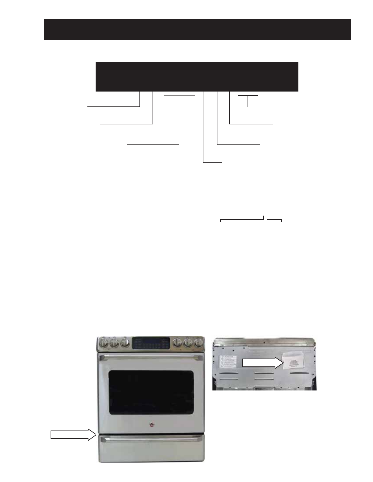
Nomenclature
C S 9 8 0 S N 1 S S
C = GE Café™
S = Slide-In
Feature Pack
The nomenclature tag of this range
is located on the oven frame behind
the lower oven drawer.
In addition to the model and serial
numbers, this tag shows the supply
voltage requirements and wattage
ratings of the elements.
The mini-manual is located behind the
range on the upper back panel.
SS = Stainless Steel
Engineering Code
Model Year
Model - Stainless
Serial Number
The fi rst two numbers of the serial number
identify the month and year of manufacture.
Example: AS123456S = January, 2009
A - JAN 2009 - S
D - FEB 2008 - R
F - MAR 2007 - M
G - APR 2006 - L
H - MAY 2005 - H
L - JUN 2004 - G
M - JUL 2003 - F
R - AUG 2002 - D
S - SEP 2001 - A
T - OCT 2000 - Z
V - NOV 1999 - V
Z - DEC 1998 - T
The letter des ig nat ing
the year re peats every
12 years.
Example:
T - 1974
T - 1986
T - 1998
Nomenclature
Mini-manual
– 5 –
Page 6
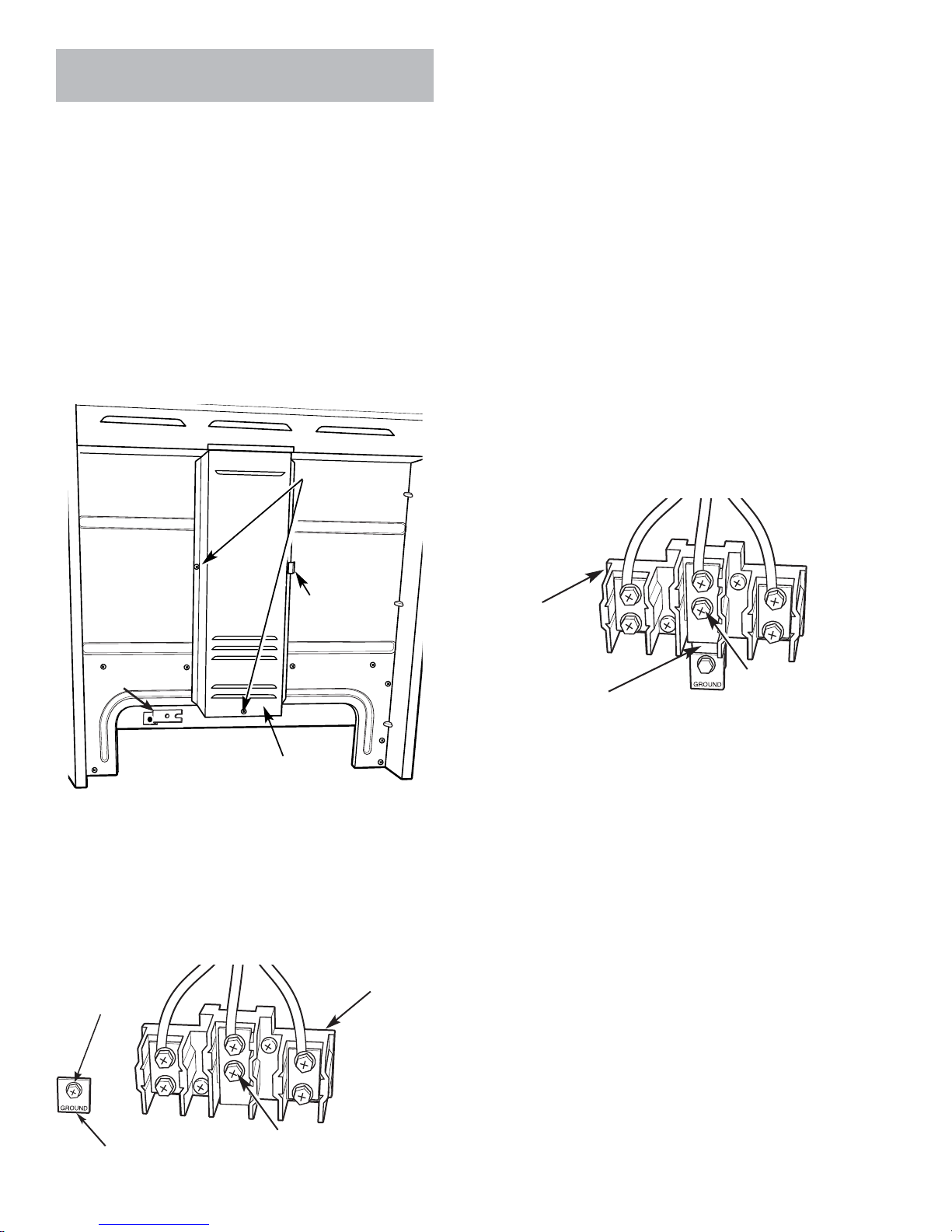
Ground Strap Installation for 3-Wire Power
Ground strap
Ground screw
Cord
Remove the two 1/4-in. hex-head screws and 1.
the wire cover from the back of the range.
WARNING: The neutral or ground wire of the power
cord must be connected to the neutral terminal
located in the center of the terminal block. The
power leads must be connected to the lower left
and the lower right terminals of the terminal block.
2. Remove the 1/4-in. hex-head screw that
attaches the copper ground strap to the lower
back of the range. Retain the copper ground
strap and return the screw to this location.
2 screws to
remove wire
cover
4. Remove the lower center screw (if present) and
loosen the upper center screw on the terminal
block.
5. Slide the open slotted end of the ground strap
under the upper center screw on the terminal
block. Make sure the ground strap is all the way
against the upper center screw and tighten it in
place.
Note: In the following step, be sure that the ground
strap does not contact any insulation that would
prevent full contact with the range frame.
6. Place the metal ground plate over the bottom of
the copper ground strap with the word GROUND
facing away from the range frame. Press strap
and plate against the range frame and attach
them with the ground screw.
7. Install the lower center screw removed in step 4.
Retaining
tab
Ground strap
Back of range
Wire cover
3. Remove the 1/4-in. hex-head ground screw,
located to the left of the terminal block, that
attaches the metal ground plate to the lower
back of the range. Retain the metal ground plate
and ground screw.
Terminal
Ground screw
block
Terminal
block
Ground strap
8. Complete the 3-wire power cord or 3-wire
conduit installation as appropriate for your
application.
Note: Wire used, location of splices, etc., must
conform to good wiring practices and local codes.
9. Place the wire cover under the retaining tab and
install the two 1/4-in. hex-head screws and the
wire cover to the back of the range.
Neutral
terminal
Neutral
Ground plate
terminal
– 6 –
Page 7

Control Features
Using the upper oven controls.
Using the upper oven controls.
(Throughout this manual, features and appearance may vary from your model)
Features and appearance may vary.
Oven Control, Clock, Timer and Features
BAKE Pad
Touch to select the bake function.
BROIL HI/LO Pad
Touch to select the broil function.
CONVECTION BAKE MULTI/1 RACK Pad
Touch to select baking with the convection
function.
CONVECTION ROAST Pad
Touch to select roasting with the convection
function.
START Pad
Must be touched to start any cooking or
cleaning function.
Display
Shows the time of day, oven temperature,
whether the oven is in the bake, broil
or self-cleaning mode, the times set for
the timer or automatic oven operations,
and if the range is locked.
SELF-CLEAN Pad
Touch to select self-cleaning function.
See the Using the self-cleaning oven section.
If “F– and a number or letter” flash in the display
and the oven control signals, this indicates a
function error code. Touch the CLEAR/OFF pad. Allow
the oven to cool for one hour. Put the oven back into
operation. If the function error code repeats, disconnect
the power to the oven and call for service.
If your oven was set for a timed oven operation
and a power outage occurred, the clock and all
programmed functions must be reset.
The time of day will flash in the display when there
has been a power outage.
OVEN LIGHT Pad
Touch to turn the oven light on or off.
DELAY START Pad
Use along with COOKING TIME or SELF
CLEAN pads to set the oven to start and
stop automatically at a time you set.
COOKING TIME Pad
Touch and then touch the number pads to set
the amount of time you want your food to
cook. The oven will shut off when the cooking
time has run out.
CLEAR/OFF Pad
Touch to cancel ALL upper oven operations
except the clock, timer and Range Lockout.
CLOCK Pad
Touch before setting the clock.
Number Pads
Use to set any function requiring numbers
such as the time of day on the clock, the
timer, the oven temperature, the internal food
temperature, the start time and length of
operation for timed baking and self-cleaning.
KITCHEN TIMER ON/OFF Pad
Touch to select the timer feature.
PROBE Pad
Touch when using the probe to cook food.
RANGE LOCKOUT Pad
Touch the RANGE LOCKOUT pad and then
touch the START pad to lock/unlock the surface
units, oven burners and control panel so they
cannot be activated.
(Continued next page)
– 7 –
Page 8

Adjust the upper oven thermostat.
Adjust the upper oven thermostat.
Using the lower oven drawer.
Adjust the lower oven thermostat.
Note: This adjustment will not affect the broiling or the self-cleaning temperatures. The adjustment will be retained in memory after a
power failure.
To Adjust the Thermostat
Touch the BAKE and BROIL HI/LO pads at the same time
1
for 3 seconds until the display shows SF.
Touch the BAKE pad. A two digit number shows in the
2
display.
Touch BAKE once to decrease (-) the oven temperature, or
twice to increase (+).
Using the lower oven drawer.
To Use the Lower Oven Drawer
Push in and turn the lower oven drawer knob to any
1
desired setting.
Allow the lower oven drawer to preheat.
2
The ON signal light is located on the upper right side of
the knob and glows when the knob is in the ON position. It
remains ON until the knob is moved to the OFF position.
The “Heating” signal light is located below the ON signal
light and glows when the heating elements are active.
Preheat is complete after the “Heating” signal has turned
off for the fi rst time with each use.
The oven temperature can be adjusted up as much as
3
35°F or down as much as 35°F. Touch the number pads
the same way you read them. For example, to change the
oven temperature 15°F, touch 1 and 5.
When you have made the adjustment, touch the START
4
pad to go back to the time of day display. Use the oven as
you would normally.
Note: The thermostat adjustment for Baking will also
affect Convection Baking or Convection Roasting.
Notes:
Always use the included drawer rack when using the
Lower Oven Drawer.
The lower oven drawer cannot be used during a self-clean
cycle of the upper oven.
Do not put food, foil or cookware directly on the bottom
of the lower oven drawer. Always use the included drawer
rack.
If foods require a cover, use only foil or lids able to
withstand baking temperatures. Do not use plastic.
Maximum height of foods that can be placed in the lower
oven drawer is 4".
Do not put liquid or water in the lower oven drawer.
Adjust the lower oven thermostat.
Note: This adjustment will not affect the broiling temperatures.
To Adjust the Thermostat
Pull the OVEN CONTROL knob off the range and look
1
at the back side. To make an adjustment, loosen
(approximately one turn), but do not completely remove,
the two screws on the back of the knob.
With the back of the knob facing you, hold the outer edge
2
of the knob with one hand and turn the front of the knob
with the other hand.
To raise the oven temperature, move the top screw toward
the right. You’ll hear a click for each notch you move the
knob.
Never place plastics, paper, canned foods or combustible
material in the lower oven drawer.
To lower the temperature, move the top screw toward the
left.
Each click will change the oven temperature
approximately 10°F. (Range is ± 60°F. from the arrow.) We
suggest that you make the adjustment one click from
the original setting and check oven performance before
making any additional adjustments.
After the adjustment is made, retighten screws so they are
snug, but be careful not to overtighten.
Re-install knob on range and check performance.
(Continued next page)
– 8 –
Page 9

Using the griddle.
Using the griddle.
Care and cleaning of the griddle.
The non-stick coated griddle provides an extra-large
cooking surface for meats, pancakes or other food
usually prepared in a frying pan or skillet.
Note: The griddle will discolor over time as it becomes
seasoned with use.
How to Place the Griddle
Caution: Place and remove the griddle only when the
griddle is cool and all surface units are turned off.
IMPORTANT: Always place and use your griddle on the
left surface units only.
Note: Do not clean the griddle in the self-cleaning oven.
Most griddled foods require cooking on a preheated
surface. Preheat griddle then switch to the desired cook
setting.
Care and cleaning of the griddle.
Cast Iron Griddle
Rinse with hot water (do not use soap), and dry
1
thoroughly.
Before cooking, prepare the surface with cooking spray
2
or vegetable oil.
After cooking, clean the griddle with a stiff brush and
3
hot water. Using soap is not recommended, and harsh
detergents should never be used.
Towel dry immediately and apply a light coat of cooking
4
spray or vegetable oil while the griddle is still warm.
Store in a cool, dry place.
5
Do not wash in a dishwasher.
6
Griddle Precautions:
If something has spilled under the griddle, it should •
be cleaned up as soon as possible to prevent “baked
on” food soil. Do not allow grease to accumulate
under the griddle as it can be a fi re hazard. Clean
under the griddle as soon as it is cool.
To turn on the surface units for the entire griddle, turn the
knob clockwise.
To turn on the surface unit for the back half of the
griddle, turn the knob counterclockwise.
Caution: The entire griddle will still become hot.
IMPORTANT NOTES:
Avoid cooking extremely greasy foods and be careful of
grease spillover while cooking.
Never place or store any items on the griddle, even when
it is not in use. The griddle can become heated when
using the surrounding surface units.
Re-Seasoning the Cast Iron Griddle
Seasoning is the process of vegetable oil absorbing
into the pores of the iron griddle. The griddle was
seasoned during manufacture. If food sticks to the
surface, or you notice a dull, gray color, the griddle
will need to be re-seasoned.
Wash the griddle with hot, soapy water and a stiff
1
brush. (It is okay to use soap this time because you
are preparing to re-season the griddle).
Rinse and dry completely.
2
Apply a thin, even coating of MELTED solid
3
vegetable shortening (or cooking oil of your choice)
to the griddle (top, sides, and bottom).
Place aluminum foil on the bottom rack of the oven
4
to catch any dripping.
Set oven temperature to 350 – 400 degrees F.
5
Do not place the griddle in the microwave.•
Always turn off all surface units before removing the •
griddle. Use caution when handling a hot griddle.
– 9 –
Place griddle upside down on the top rack of the
6
oven.
Bake the griddle for at least one hour. After the
7
hour, turn the oven off and let the griddle cool in the
oven.
Store the griddle uncovered, in a cool, dry place
8
when cooled.
Page 10

Component Locator Views
Front View (Shown with Oven Door Removed)
Control Panel
Meat Probe Outlet
Convection Fan
Broil Element
Oven Temperature Sensor
Lower Oven Drawer
Lower Oven Compartment (Shown with Lower Oven Drawer Removed)
Thermostat Capillary Tube
Bake Element
Broil Element
Bake Element
Roller Catch
(Continued next page)
– 10 –
Page 11

Rear View (Shown with Back Cover, Terminal Cover and Griddle Relay Cover Removed)
Cooling Fan
Broil Element
Convection Element
Convection Fan Motor
Range Lockout Relay
Bake Element
Griddle Relay #1
Griddle Relay #2
Rangetop (Shown with Rangetop wire harnesses and ground wire disconnected.)
Hot Surface Indicator Light Assembly
Dual Surface Element
Dual Surface Element
Single Surface Element
Single Surface Element
Cook-Warm Zone Surface Element
Thermal Switch
– 11 –
Page 12

Range Components
WARNING: Sharp edges may be exposed when servicing. Use caution to avoid injury. Wear Kevlar gloves or
equivalent protection.
Lower Oven Drawer
The lower drawer can be removed by pulling the
drawer straight out until it stops, pressing the tabs
fi rmly inward on both sides of the drawer rails and
pulling the drawer forward until disengaged from
the drawer guides.
Note: When in the closed position, the strike on the
back of the drawer is captured by the roller catch.
The strike is riveted in place and is not adjustable.
The roller catch is attached to the range fl oor with
two 1/4-in. hex-head screws that, when loosened,
can provide a small amount of adjustment.
Range Floor
Back of Drawer
Roller Catch
Strike
Rangetop
To remove the rangetop:
Pull out the range from its installation.1.
The lower drawer can be installed by placing each
drawer rail around each inner rail guide and sliding
both in slightly to hook them, then fi rmly sliding the
drawer all the way in.
Remove the three 1/4-in. hex-head screws that 2.
attach the vent trim to the rangetop.
Lift and remove the vent trim.3.
Vent Trim
4. Remove the two 1/4-in. hex-head screws that
attach the rangetop to the range.
Rangetop
5. Raise the rear of the rangetop, then slide the
rangetop toward the rear of the range about 6
inches.
– 12 –
(Continued next page)
Page 13

6. Remove the two 1/4-in. hex-head screws and
the heat shield from the range.
Heat Shield
3. Remove the 2 Phillips-head locator pins from the
top of the range.
4. Place a towel or protective item across the top
of each side panel.
5. Slide the control panel forward, rotate and place
the panel top down across the range on the
protective surfaces as shown.
Note: When installing
Locator Pin
rangetop, be sure to
engage slots in rangetop
underneath locator pins.
7. Disconnect the 2 rangetop wire harnesses.
8. Remove the 1/4-in. hex-head screw that
attaches the ground wire to the range.
Disconnect
Disconnect
9. Carefully lift the rangetop and place it on a
protective surface.
Service Position
Electronic Range Control (ERC)
The ERC is attached to a bracket that houses the
touch panel. It is necessary to remove the bracket
from the control panel to access the screws that
attach the ERC. Viewed in the service position, the
bracket is attached with 2 Phillips-head screws at
the top and 2 tabs at the bottom that lock into a fold
in the control panel.
To remove the electronic oven control (ERC):
Place the control panel in the service position. 1.
(See Control Panel.)
Mark and disconnect all wiring from the ERC.2.
Note: When installing the rangetop, be sure both
rangetop wire harnesses are positioned underneath
the heat shield.
Control Panel
To access the control panel:
Remove the rangetop. (1.
Remove the 4 Phillips-head screws from the 2.
bottom of the control panel.
See Rangetop.)
Remove the 2 Phillip-head screws from the top 3.
of the control panel.
(Continued next page)
– 13 –
Page 14

4. Carefully lift the 2 tabs out from the panel fold,
then remove the ERC from the control panel.
4. Reach behind the element and pull off the 2
element wire connectors.
5. Remove the two 1/4-in. hex-head screws that
attach the element to the oven fl oor.
Tab
Panel Fold
Tab
5. Remove the four T-15 torx screws that attach
the ERC to the bracket.
Lower Oven Bottom Element
To remove the lower oven bottom element:
Remove the lower oven drawer. (See 1. Lower Oven
Drawer.)
Remove the 2 slotted screws and the oven rear 2.
panel.
6. Remove element from the oven.
Note: When installing the element, be sure to place
element under the 3 retainers before installing
element-to-fl oor screws.
Retainers
Lower Oven Top Element
To remove the lower oven top element:
Remove the lower oven drawer. (See 1. Lower Oven
Drawer.)
Remove the 2 slotted screws and the oven rear 2.
panel. (See Lower Oven Bake Element.)
Oven Rear Panel
3. Remove the two 1/4-in. hex-head screws that
attach the bottom element terminal cover.
Place cover aside.
Remove the two 1/4-in. hex-head screws that 3.
attach the top element terminal cover. Place
cover aside.
(Continued next page)
– 14 –
Page 15

4. Reach behind the element and pull off the 2
element wire connectors.
5. Remove the six 1/4-in. hex-head screws that
attach the top element to the oven ceiling.
Lower Oven Control
To remove the lower oven control:
Remove the rangetop. (See 1. Rangetop.)
6. Squeeze and remove the capillary bulb clips and
remove them from the holes in the oven ceiling.
Holes in Ceiling
7. Remove the 4 Phillips-head screws and the
locator pin from the top of the left side panel.
8. Remove the six 1/4-in. hex-head screws from
the back of the left side panel.
9. Carefully spread the rear of the left side panel
out from the range approximately 10 inches.
Remove the lower oven control knob. 2.
Remove the 2 Phillips-head screws and the 3.
control from the control panel.
4. Mark and remove the wires from the control.
5. Push up and release the capillary bulb from
each capillary bulb clip.
Capillary Bulb Clip
Capillary Bulb
10. Push the capillary bulb through the entry hole
while pulling the capillary from the range.
– 15 –
Page 16

Lower Oven Operation
Note: The lower oven cannot be used during a self-clean cycle of the upper oven.
The lower oven operates in the following manner:
When the lower oven control is turned counterclockwise,
The control contacts • COM to NO close supplying L1 to the baking elements, pilot lamp and heating lamp.
The pilot lamp will be lit because neutral is not interrupted.•
The control cycling contacts • N to H close supplying Neutral to the baking elements and heating lamp.
Note: When the control is turned counterclockwise, both elements are at L1 potential regardless of the status
of contacts N to H. Neutral is cycled to control oven temperatures.
– 16 –
Page 17

Range Lockout Relay
The range lockout feature (on some models), allows
the user to lockout the surface units, upper oven,
and control panel so they cannot be activated.
When the control is set for RANGE LOCKOUT, the
control deactivates the upper oven and control
panel and energizes the lockout relay that locks out
the surface units so they cannot be activated. (See
Control Features.)
The control RY3 relay will close and complete the
circuit that supplies the voltage to the lockout relay.
Griddle Operation
The griddle, placed over the left side surface
elements, can be heated using the rear element
only or both the front and rear elements at the
same time. Two relays are used to allow only the left
rear infi nite heat switch to operate both front and
rear elements.
When the left rear control is turned clockwise to
select griddle:
P2 closes to 4, supplying L1 voltage to the left •
rear element.
The relay is also energized when the oven door is
locked (COM to NO closed). When energized, the
lockout relay will open contacts 7 to 1 and 9 to 3,
disconnecting L2 from the surface units.
EOC
SW4 LATCH
COM
NO
NC
TO LOWER OVEN
THERMOSTAT
TO SURFACE
UNITS
Relay 1 (now operating on 240VAC) simultaneously:
Disconnects the left front control element •
cycling contacts, P1 to 2, and connects both left
front elements directly to L2.
Connects L1 voltage directly to both left front •
elements.
Contacts P1 to 2, on the left rear control, now cycle
L2 voltage to both the left rear element and to relay
1, which now operates both left front elements.
P2 closes to S2, supplying L1 voltage to the left •
surface indicator light.
P2 closes to 4a, supplying L1 voltage to the •
griddle ON indicator light, relay 1 and relay 2.
Relay 2 (now operating on 120VAC) disconnects •
L1 voltage from the left front control.
Note: With the griddle turned off and the left rear
hot surface light on (glass temperature above
150°F), 27 VAC will be applied to relay 2 and 97 VAC
will be applied to relay 1. During this time, both
relays may produce a slight hum/vibration. Neither
relay will be operating. The hum/vibration will cease
once the hot light switch contacts 1b to 2b open.
– 17 –
Page 18

Cooling Blower
Convection Fan Assembly
The two-speed cooling blower is located on the rear
of the range. Air is pulled in by the blower blades
through slots below the control panel and circulated
in the space below the component compartment
and above the top of the oven liner. The air is
exhausted through the right side of the oven vent
trim.
Low speed is used for cooking functions and high
speed is used only in the self-clean mode. The
blower is operated by the ERC (a function of oven
temperature), when cooling timing parameters are
met. Blower speed is determined by the position of
door latch switch #3. (See Door Lock Assembly.)
Cooling Timing Parameters
The cooling blower will not turn on immediately
when a cooking function is set. IT WILL TURN
ON WHEN THE OVEN TEMPERATURE REACHES
APPROXIMATELY 450°F. If the oven is turned off and
the blower is running, the blower will remain on until
the oven temperature drops to below 300°F.
Cooling blower motor approximate resistance
values:
Low speed (C to L) = 20 • Ω
High Speed (C to H) = 24 • Ω
The convection fan assembly is located on the
back wall of the oven cavity and consists of the
convection cover, fan blade, and motor. The fan
motor utilizes a capacitor that can be accessed
from the back of the range. (See Component Locator
Views.) The convection fan blade can be removed
from inside the oven. The convection fan motor can
be removed from the back of the range.
The convection fan operates during the following
modes:
Preheat•
Convection Bake•
Convection Roast•
The convection fan will turn on after a short delay.
The fan may cycle on and off, and change direction
in any of these modes, to best distribute hot air in
the oven. The convection fan shuts off when the
door is opened.
The convection element is located on the upper
oven back wall and can be removed from inside the
oven cavity.
The element is rated at 1200 watts, has an
approximate resistance value of 12 Ω, and draws
approximately 10 amps.
To remove the cooling blower, it is necessary to
remove the rangetop (See
Rangetop.), and rear
panel. The cooling blower assembly is attached with
six 1/4-in. hex-head screws.
L
H
C
OPERATING CHARACTERISTICS
Convection Bake - Single Rack preheats with
bake element and broil element operating (cycling)
alternately. Heat maintained with bake element.
Fan alternates CW and CCW rotation.
Preheat
Red box indicates cycling contacts
(Continued next page)
– 18 –
Page 19

Heat Maintained
Red Box indicates cycling contacts
Convection Bake - Multi Rack preheats with bake
element and broil element operating (cycling)
alternately. Heat maintained with convection
element only. Fan alternates CW and CCW rotation.
Preheat
Convection Roast preheats with bake element and
broil element operating (cycling) alternately. Heat
maintained with bake element and broil element
operating (cycling) alternately. Fan rotates CCW.
Preheat and Heat Maintained
Red Box indicates cycling contacts
Thermal Switch
The thermal switch is located under the rangetop
on the burner box fl oor and protects the electronics
from damage should a high temperature condition
occur when the range is in the self-clean mode.
Red Box indicates cycling contacts
Heat Maintained
Red Box indicates cycling contacts
Thermal Switch
The thermal switch is wired in series with the lock
motor switches. The thermal switch opens at 265°F.
The switch closes when temperatures cool below
approximately 220°F. If the thermal switch opens
during the following conditions:
Oven Temperature Below 600°F (315°C). •
Program is cancelled when thermal switch
opens. Lock motor will run and the word
LOCKED will be fl ashing in the display.
Oven Temperature Above 600°F (315°C). Any •
mode of operation control will go to -F2- failure
code. When this condition exists, check the
fan operation (look for obstructions), inspect
oven installation (make sure grill areas are not
blocked), oven insulation, and lock circuit.
– 19 –
Page 20

Electronic Range Control (ERC) Pin Locator
TB640
TB102
TB101
TB650
TB655
TB630
TB620
RY 500A1
RY 540B
RY 502A1
RY 501A1
TB660
TB661
CN2 - Sensor, Thermal Switch, Door Lock,
Switch, Door Unlock Switch, Probe
Switch, Door Unlock Switch, Probe
CN950 - Glass Touch Board
RY500A1 - Broil
RY501A1 - Bake
RY502A1 - Convection Element
RY540B - Double Line Break
CN2
CN950
TB101 - L1
TB102 - Neutral
TB620 - Oven Light
TB630 - Door Lock Switch
TB640 - Door Lock Switch, Lock Out Relay
TB650 - Convection Motor CW
TB655 - Convection Motor CCW
TB660 - Door Lock Motor
TB661 - Door Lock Common
– 20 –
Page 21

Door Lock Assembly
The door lock assembly consists of a lock motor
cam and switch assembly (switches #1, #2, #3, and
#4), lock hook, and mounting plate.
The lock motor is energized when the control is set
for CLEAN and START is selected. The RY1 relay
contacts will close and complete the circuit that
supplies the voltage to the lock motor.
UNLOCKED
DOOR LATCH OUTPUT PIN
DOOR LATCHED INPUT PIN
DOOR UNLATCHED INPUT PIN
DOOR LATCH OUTPUT PIN
DOOR LATCHED INPUT PIN
DOOR UNLATCHED INPUT PIN
CN2
CN2
5
4
3
5
4
3
LOCKED
DOOR LOCK DOOR UNLOCK
SW1 LATCH
THERMAL
SWITCH
DOOR LOCK DOOR UNLOCK
SW1 LATCH
THERMAL
SWITCH
SW2 LATCH
SW2 LATCH
• CAM – The cam on the motor performs two
functions:
Positions the lock hook in the door to prevent 1.
opening during clean operation.
Operates the lock switches which tell the control 2.
if the door is unlocked or locked and ready for
clean operation.
Note: When the door is either being locked or
unlocked, both lock switches will be in the open
position.
Switch #3 controls cooling fan motor speed. Hi
speed is used when the self-clean cycle is selected
and the door is locked and low speed for other oven
selections when the door is unlocked.
COOLING FAN
The lock switch circuit “tells” the control if the
lock motor is in the unlocked or locked position or
somewhere in between. There are two lock switches
mounted to and operated by the lock motor.
The lock switch circuit is from the control, through
one of the lock switches (switch #2 for unlocked or
switch #1 for locked), back to the control. If neither
switch is closed, and the oven temperature is below
600°F (315°C), control will energize the lock motor
circuit until the correct switch closes to complete
the circuit. (If circuit to the correct switch is open,
lock motor will run continuously with the oven
below 600°F [315°C].)
Note: If initiating a clean cycle with the door switch
in the “C” to “NC” position (door open), the control
display will fl ash “LOCKED” and will sound a series
of beeps, followed by cancellation of the clean
selection.
• The word “LOCKED” will fl ash on and off in the
display while the lock motor is in motion. When
the door is locked, the word “LOCKED” will remain
illuminated in the display.
Switch #4 locks out the lower oven and all surface
units when the self-clean cycle is selected and the
door is locked.
LOCKOUTS IN CLEAN CYCLE
The door lock motor has an approximate resistance
value of 2K Ω.
The resistance of the door lock motor can be
checked on the ERC. Place the control panel in the
service position. (See
Control Panel.)
With the door closed, test between TB660 (MDL) and
N on the ERC for the approximate resistance value.
– 21 –
(Continued next page)
Page 22

Lock Assembly Removal
The lock assembly is attached to the front of the range by two T-15 Torx screws. To replace the door lock it
is necessary to place the control panel in the service position (See
Control Panel.), remove the lock assembly
insulation, and two 1/4-in. hex-head screws and the lock assembly cover.
Door Lock Assembly (top view shown with insulation and cover removed)
Door Lock Assembly (removed, rear view shown)
Switch #2
C
NC
NC
NO
NO
NO
Switch #3
C
Switch #4
C
Lock Motor
Switch #1
C
NO
Switch Function Door UnLocked Door Locked C NO NC
1 Door Lock C - NO open C - NO closed Yellow Gray N/A
2 Door Unlock C - NO closed C - NO open Yellow Orange N/A
3 Cooling Fan Motor Speed
Hi speed in clean, Low speed
in other modes
4 Lower oven and all surface
unit lockout in Clean cycle
C - NO closed
C - NC open
C - NO closed
C - NC open
C - NO open
C - NC closed
C - NO open
C - NC closed
Gray/Red Black Blue
Red Violet Brown
Caution: It is possible to reconnect the switch wiring incorrectly to the lock assembly. When reconnecting
the wiring, make sure it is properly connected to the lock assembly before turning the power back on.
– 22 –
Page 23

Diagnostics and Service Information
ERC Failure Codes
The oven may stop operating but not give an F code on the display immediately. F codes are stored in non
volatile eeprom memory until 2 of the same fault occur consecutively. After that, it will be displayed. They
can be recalled by pressing together: TIMER, CLOCK, 9. While displayed, pressing 8 and 6 together will clear
them. A fault must exist continuously for 5 minutes before an F code is recorded (F2, F8 are sooner).
FAILURE
CODE
-F0- Shorted OFF key Determine if problem is with Key Panel or control by disconnecting
-F2- Over temperature inside
oven cavity as measured
by sensor over 600°F
unlatched or 915°F
latched.
-F3- Open oven sensor (over
2900 ohms)
-F4- Shorted oven sensor
(under 950 ohms)
MEANING CORRECTION
ribbon cable and measuring fl at cable pins 13 to 14. Should be open.
Should be 100-150 ohms while pressing OFF key.
- Welded relay contacts
- Cooling fan stalled or blocked
- Airfl ow to rear of unit
- High resistance in oven sensor leads/connectors
- (especially at sensor in rear)
- Disconnect power.
- Disconnect sensor harness from control. Measure sensor resistance
(white leads) to be -1080 ohms at room temperature with 2 ohms per
degree change.
- Look for damaged harness terminals if not a bad sensor.
- Disconnect power.
- Disconnect sensor harness from control. Measure sensor resistance
(white leads) to be -1080 Ω at room temperature with 2 ohms per
degree change.
- Look for damaged harness terminals if not a bad sensor
-F5- A to D system fault Replace control
-F6- Range Lockout - Switch
issues
-F7- Shorted matrix or START
key
-F8- EEPROM data shift failure If repeated, replace control
-F9- Door Lock false while
above Runaway
Setpoint, Unlatched Door
Lock temperature. OR
Thermal switch device
setpoint exceeded.
Check connections on lockout motor and CN6 of control.
Determine if problem is with Key Panel or control by disconnecting
ribbon cable and measuring fl at cable using pinout chart. Allow up to
1000 ohms when pressing key.
“Unlock” Latch Changing status to “Lock” while cooking or “Lock”
Latch of Motor changing to “Un-Lock” while above run away set point
– 23 –
Page 24

Schematic
WARNING: Disconnect electrical power before servicing.
Caution: Label all wires prior to disconnection. Wiring errors can cause improper and dangerous operation.
Verify operation after servicing.
Schematic Diagram
– 24 –
Page 25

Warranty
GE Electric Range Warranty. (For customers in the United States)
All warranty service provided by our Factory Service Centers,
or an authorized Customer Care
®
technician. To schedule
service, on-line, 24 hours a day, visit us at ge.com, or call
800.GE.CARES (800.432.2737). Please have serial number
Staple your receipt here.
Proof of the original purchase
date is needed to obtain service
under the warranty.
and model number available when calling for service.
For The Period Of: GE Will Replace:
One Year Any part of the range which fails due to a defect in materials or workmanship. During this
From the date of the limited one-year warranty, GE will also provide, free of charge, all labor and in-home service
original purchase to replace the defective part .
Five Years A replacement glass cooktop if it should: crack due to thermal shock; discolor; crack at the
From the date of the rubber seal between the glass cooktop and the porcelain edge, or if the pattern wears off.
original purchase
A replacement radiant surface unit if it should burn out.
During this limited additional four-year warranty, you will be responsible for any labor or
in-home service.
What GE Will Not Cover:
■ Service trips to your home to teach you how to use
the product.
■ Improper installation, delivery or maintenance.
■ Failure of the product if it is abused, misused,
or used for other than the intended purpose or
used commercially.
■ Damage to the glass cooktop caused by hardened
spills of sugary materials or melted plastic that
are not cleaned according to the directions in
the Owner’s Manual.
■ Damage to the glass cooktop caused by use of cleaners
other than the recommended cleaning creams.
■ Replacement of house fuses or resetting of circuit
breakers.
■ Damage to the product caused by accident, fire, floods
or acts of God.
■ Incidental or consequential damage caused by possible
defects with this appliance.
■ Damage caused after delivery.
■ Product not accessible to provide required service.
EXCLUSION OF IMPLIED WARRANTIES—Your sole and exclusive remedy is product repair as provided in this Limited
Warranty. Any implied warranties, including the implied warranties of merchantability or fitness for a particular
purpose, are limited to one year or the shortest period allowed by law.
This warranty is extended to the original purchaser and any succeeding owner for products purchased for home
use within the USA. If the product is located in an area where service by a GE Authorized Servicer is not available,
you may be responsible for a trip charge or you may be required to bring the product to an Authorized GE Service
location for service. In Alaska, the warranty excludes the cost of shipping or service calls to your home.
Some states do not allow the exclusion or limitation of incidental or consequential damages. This warranty
gives you specific legal rights, and you may also have other rights which vary from state to state. To know
what your legal rights are, consult your local or state consumer affairs office or your state’s Attorney General.
Warrantor: General Electric Company. Louisville, KY 40225
– 25 –
 Loading...