

Page 1

Installation Instructions
Range
Questions? call 1.800.GE.CARES (1.800.432.2737) or visit www.GEAppliances.com
IN THE COMMONWEALTH OF
MASSACHUSETTS
[] This product must be installed by a licensed
plumber or gas fitter.
[AWARNINGi
FIRE OR EXPLOSION HAZARD
If the information in this manual is not followed
exactly, a fire or explosion may result causing
property damage, personal injury or death.
Installation must be performed by a qualified
installer.
Read these instructions completely and carefully.
Installation of this range must conform with
local codes, or in the absence of local codes,
with the National Fuel Gas Code, ANSI Z223.1/
NFPA.S4,latest edition. In Canada, installation
must conform with the current Natural Gas
Installation Code, CAN/CGA-B149.1 or the current
Propane Installation Code, CAN/CGA-B149.2, and
with local codes where applicable. This range
has been design-certified by CSAInternational
according to ANSI Z21.1, latest edition and
Canadian Gas Association according to CAN/
CGA-I.1 latest edition.
[] When using ball type gas shut-off valves, they
shall be the T-handle type.
[] A flexible gas connector, when used, must not
exceed 3 feet.
When installing a gas appliance the use of old
flexible connectors can cause gas leaks and
personal injury. Always use a NEW flexible
connector.
Leak testing of the appliance shall be conducted
according to the manufacturer instructions.
The range must be electrically grounded in
accordance with local codes or, in the absence
of local codes, in accordance with the National
Electrical Code (ANSI/NFPA70, latest edition).
In Canada, electrical grounding must be in
accordance with the current CSAC22.1 Canadian
Electrical Code Part Z and/or local codes. See
Electrical Connections in this section.
Do not install this product with an air curtain
hood or other range hood that operates by
blowing air down on the cooktop. This airflow
may interfere with operation of the gas burners
resulting in fire or explosion hazard.
FOR YOUR SAFETY:
A child or adult can tip the range and be killed.
Install the anti-tip bracket to the wall or floor.
Engage the range to the anti-tip bracket by sliding the
range back such that the foot is engaged.
Re-engage the anti-tip bracket if the range is moved.
Failure to do so can result in death or serious burns
to children or adults.
If you did not receive an anti-tip bracket with your
purchase, call 1.800.626.8774 to receive one at no
cost. (In Canada, call 1.800.561.3344.) For installation
instructions of the bracket, visit: www.GEAppliances.com.
(In Canada, www.GEAppliances.ca.)
Tip-Over Hazard
Kit Included
Anti-TipBracket
[IkWARNING] Beforebeginning
theinstallation,switchpower offat
servicepaneland locktheservice
disconnectingmeans to preventpower
frombeingswitchedon occidentally.
When theservicedisconnectingmeans
cannotbe locked,securelyfasteno
prominentwarningdevice,such aso
tog,totheservicepanel.
ACAUTION - Only the GE Caf@ branded over-the-range oven above a GE Caf@ range
series of Advantium® or microwave over-
the-range ovens are designed to be installed cause burns.
above the GE Caf@ range. Surfaces above a gas
range can become hot. Installation of any other
may result in surface temperatures that can
Page 2

TOOLS YOU WILL NEED
Phillips
screwdriver
Open-end or
Flat-blade
screwdriver
Penciland ruler
Pipewrenches(2)
(onefor backup)
1/4" NutDriver
TapeMeasure
TinSnips
adjustable wrench
Drill,awl or nail
Drillwith 1/8"Bit
Safety Glasses
Level
Pliers
MATERIALS YOU MAY NEED
[] Gas line shut-off valve
[] Pipejoint sealant or UL-approved pipe thread
tape with Teflon* that resists action of natural
and LP gases
[] Flexible metal appliance connector (1/2" I.D.).
A 5-foot length is recommended for ease of
installation but other lengths are acceptable.
Never use an old connector when installing a
new range.
[] Flare union adapter for connection to gas
supply line (3/4" or 1/2" NPTx 1/2" I.D.)
[] Hare union adapter for connection to pressure
regulator on range (1/2" NPT x 2/2" I.D.)
[] Liquid leak detector or
soapy water.
[] Squeeze Connector
(ForConduit Installations Only)
8-Wire Cord 8' long OR
[] (ULListed 80 AMP)
3-Wire Cord 4' long
*Teflon: Registered trademark of DuPont
BEFORE YOU BEGIN
IMPORTANT -- Save these instructions for
local inspector's use.
IM PORTANT -- Observe all governing
codes and ordinances.
IM PORTANT -- Remove all packing
material and literature from oven before
connecting gas and electrical supply to range.
IMPORTANT -- To avoiddamage toyour
cabinets,checkwithyour builderorcabinet
suppliertomake surethatthematerialsusedwill
notdiscolor,delaminateorsustainotherdamage.
Thisoven hasbeen designedinaccordancewith
therequirementsofUL and CSA International
and complies with the maximum allowable wood
cabinet temperatures of 194% (90°C).
Note to Installer i Be sure to leave these
instructions with consumer.
Note to consumer i Keep these instructions for
future reference.
Servicer i The electrical diagram is in an
envelope attached to the back of the range.
Proper installation is the responsibility of the
installer.
Product failure due to improper installation is not
covered under warranty.
Before installing your range on linoleum or any
other synthetic floor covering, make sure the
floor covering can withstand 180°F without
shrinking, warping or discoloring. Do not install
the range over carpeting unless a sheet of 1/4"
thick plywood or similar insulator is placed
between the range and carpeting.
Mobile Home - Additional Installation
Requirements
The installation of this range must conform to
the Manufactured Home Construction and Safety
Standard, Title 24 CFR,Part 3280 (formerly the
Federal Standard for Mobile Home Construction
and Saftey, Title 24, HUD Part 280). When such
standard is not applicable, use the Standard for
Manufactured Home Installations, ANSI A225.1/
NFPA501A or with local codes.
In Canada, the installation of this range must
conform with the current standards CAN/CSA-
A240-1atest edition, or with local codes.
When this range is installed in a mobile home, it
must be secured to the floor during transit. Any
method of securing the range is adequate as
long as it conforms to the standards listed above.
Page 3

DIMENSIONS AND CLEARANCES
Provide adequate clearances between the
range and adjacent combustible surfaces. These
dimensions must be met for safe use of your
range.
Allow 30" (76.2 cm) minimum clearance between
burners and bottom of unprotected wood or
metal cabinet, or allow a 24" 161cm) minimum
when bottom of wood or metal cabinet is
protected by no less than 2/4" (6.4 mm) thick
flame-retardant millboard covered with no less
than No. 28 MSGsheet metal (.015" [.38 mm]
........ _ ................. 30 ............... "_-29 Y"
*41Xz"
*Height to backguard based on
Caf6 style backguard kit installed.
thick), .015" (.38mm) thick stainless steel, .025"
(0.64 mm) aluminum or .020" (0.5mm) copper.
Installation of a listed microwave oven or
cooking appliance over the cooktop shall
conform to the installation instructions packed
with that appliance.
For island installation, maintain 2-2/2" minimum
from cutout to back edge of countertop and
3" minimum from cutout to side edges of
countertop.
Depth with door closed
p._ (includes door handle]
DIMENSIONS AND CLEARANCES (CONT.)
GAS PiPE AND ELECTRICAL OUTLET LOCATIONS
If the countertop has a
raised edge, shave the
raised edge to clear
the control panel as
shown below.
Recommended area
for through-the-Wall
connection of
and shut-off valve.
Recommended acceptable
Recommended area
for through-the-floor
connection of pipe
stub and shut-off valve.
electrical outlet area. Orient
the electrical receptacle so the
length is parallel to the floor.
[_,CAUTION JTo prevent drafts from affecting burner operation, seal all openings in floor
under appliance and behind appliance wall.
Depth with door open: _\\
M,n mumto1II1 --i
cabinetson l|_
eitherside H A
ofthe range 1}__T 30"
Hin h.num-'_/Minimum
18",
clearance |
toleft wall
Tocabinets
belowcooktop
andat the -_ -0"
rangeback
SH l of 2 31-10982 C2S985 08-14 GE
\
46L" \
\
._t-- 6"
Minimum
clearance to
right wall
depth for
cabinets above
Maximum J_
countertops
1/4"
Tocabinets
belowcooktop
andat the
rangeback
Page 4

CONVERTING TO LP GAS
(OR CONVERTING BACK TO
NATURAL GAS FROM LP)
This range leaves the factory set for use with
natural gas. If you want to convert to LP
gas, the conversion must be performed by a
qualified LP gas installer.
The conversion orifices and instructions can be
found on back of the range.
Keep these instructions and all orifices in case
you want to convert back to natural gas.
Orifice Box
(location
may vary) \
Reor of Range
f
............_ ....... d' l
Page 5

r_ ELECTRICAL REQUIREMENTS
AWARNING: This appliance must be
properly grounded.
AWARNIN G: All new constructions, mobile
homes, recreational vehicles and installations where
local codes do not allow grounding through neutral,
require a 4-conductor UL-listed range cord.
AWARNING: TOprevent fire or shock, do
not use an extension cord with this appliance.
AWARN ING: Toprevent shock,remove
house fuse or open circuit breaker before
beginning installation.
We recommend you have the electrical wiring
and hookup of your range connected by a
qualified electrician. After installation, have the
electrician show you how to disconnect power
from the range.
You must use a single-phase, 120/208 VAC or
120/240 VAC,60 hertz electrical system. Ifyou
connect to aluminum wiring, properly installed
connectors approved for use with aluminum
wiring must be used.
Effective January 1,1996, the National Electrical
Code requires that new construction (not
existing) utilize a 4-conductor connection to an
electric range. When installing an electric range
in new construction, mobile home, recreational
vehicle, or an area where local codes prohibit
grounding through the neutral conductor, refer to
the section on four-conductor branch circuit
connections.
Checkwith your localutilities for electricalcodes
whichapplyin your area.Failuretowire your
ovenaccording to governingcodescould result
in a hazardous condition. If there are no local
codes, your oven must be wired and fused to
meet the National Electrical Code, NFPA No.
70 i latest edition, available from the National
Fire Protection Association.
This appliance must be supplied with the proper
voltage and frequency, and connected to an
individual, properly grounded, 40 amp (minimum)
branch circuit protected by a circuit breaker
or time-delay fuse.
Use only a 3-conductor or a 4-conductor
UL-listed range cord. These cords may be
provided with ring terminals on wire and a strain
relief device.
A range cord rated at 40 amps with 125/250
minimum volt range is required. A 50 amp range
cord is not recommended but if used, it should
be marked for use with nominal 1_" diameter
connection openings. Care should be taken to
center the cable and strain relief within the
knockout hole to keep the edge from damaging
the cable.
The rating plate is located on the oven frame or
on the side of the drawer frame.
Note: Use of automatic, wireless or wired external
switches that shut off power to the appliances,
are not recommended for this product.
SINGLE OVEN
Ratingplate
[_] POWER CORD AND CONDUIT INSTALLATION
r_ Access the terminal block by removing range
wire cover screws using a 1/4" nut driver.
Do not discard these screws.
@
Forpower cord and 1"conduit on)y,remove
the knockout ring (lS/j ') located on bracket
directly below the terminal block. To
remove the knockout, use a pair of pliers
to bend the knockout ring away from the
bracket and twist until ring is removed.
Backof
Retaining
tabs
Wire cover
Terminal block
(appearance
may vary)
Knockout
ringin {_'
bracket /
I
D
For power cord installations only (see the
next step if using conduit), assemble the
strain relief in the hole. Insert the power
cord through the strain relief and tighten.
Allow enough slack to easily attach the
cord terminals to the terminal block. If
tabs are present at the end of the winged
strain relief, they can be removed for
better fit.
NOTE:Do not install the power cord
without a strain relief. The strain relief
bracket MUSTbe installed before
reinstalling the rear range wiring cover.
Knockout ring _")
removed "___
5 screws to
cover
@
For 3/4" conduit installations only, purchase
a squeeze connector matching the diameter
ofyour conduit and assemble it in the hole.
Insert the conduit through the squeeze
connector and tighten.Allow enough slack
to easilyattach the wires to the terminal
block. NOTE:Donot install the conduit
without a squeeze connector. The
squeeze connector IvlUSTbeinstalled
before reinstalling the rear range wiring
cover.
PROCEED TO STEP 3 or 4
Squeeze
connector
Page 6
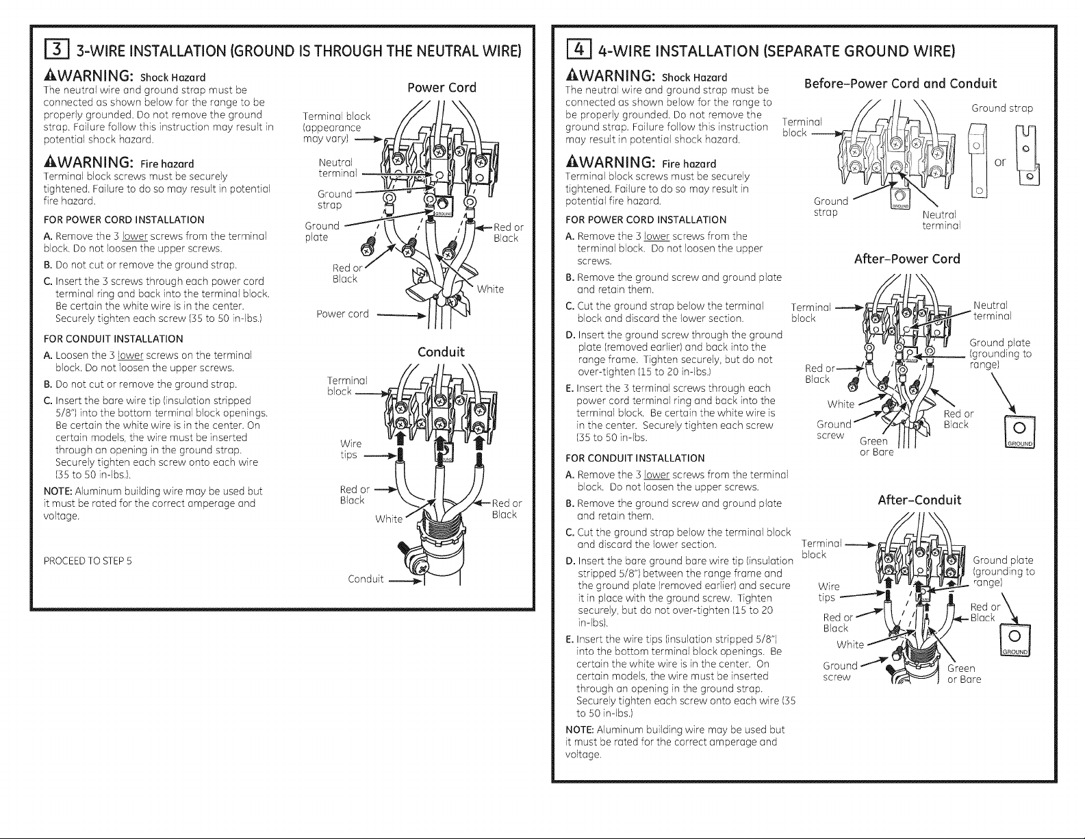
3-WIRE INSTALLATION (GROUND IS THROUGH THE NEUTRAL WIRE}
AWARNING: Shock Hazard
The neutral wire and ground strap must be
connected as shown below for the range to be
properly grounded. Do not remove the ground
strap, Failure follow this instruction may result in
potential shock hazard.
AWARNING: Firehazard
Terminal block screws must be securely
tightened. Failure to do so may result in potential
fire hazard,
FORPOWER CORD INSTALLATION
A. Remove the ] lower screws from the terminal
block, Do not loosen the upper screws,
B. Do not cut or remove the ground strap,
C. Insert the ] screws through each power cord
terminal ring and back into the terminal block.
Becertain the white wire is in the center,
Securely tighten each screw (IS to SOin-lbs.)
FOR CONDUIT INSTALLATION
A. Loosen the ] lower screws on the terminal
block. Do not loosen the upper screws.
B. Do not cut or remove the ground strap.
C. Insert the bare wire tip (insulation stripped
5/8") into the bottom terminal block openings.
Becertain the white wire is in the center. On
certain models, the wire must be inserted
through an opening in the ground strap.
Securely tighten each screw onto each wire
(IS to SOin-lbs.).
NOTE:Aluminum building wire may be used but
it must be rated for the correct amperage and
voltage.
PROCEED TO STEP 5
Terminal block
(appearance
may vary)
Neutral
terminal
Ground
strap
Ground
plate
Red ol
Black
Power cord
; o7
Wire m - "i-_ "11 -u
Redor_',. II //
Conduit _ ----I
Power Cord
Conduit
White
Red or
Black
4-WIRE INSTALLATION (SEPARATE GROUND WIRE}
AWARNING: Shock Hazard
The neutral wire and ground strap must be
connected as shown below for the range to
be properly grounded. Do not remove the
ground strap. Failure follow this instruction
may result in potential shock hazard.
Before-Power Cord and Conduit
Terminal F/_--_
AWARN ING: Fire hazard
Terminal block screws must be securely
tightened. Failure to do so may result in
potential fire hazard,
FOR POWER CORD INSTALLATION
A. Remove the ] lower screws from the
terminal block. Do not loosen the upper
screws.
B.Remove the ground screw and ground plate
and retain them.
C.Cut the ground strap below the terminal
block and discard the lower section.
D. Insert the ground screw through the ground
plate (removed earlier) and back into the
range frame. Tighten securely, but do not
over-tighten (15 to 20 in-lbs.)
E.Insert the ] terminal screws through each
power cord terminal ring and back into the
terminal block. Becertain the white wire is
in the center. Securely tighten each screw
(35 to 50 in-lbs.
FOR CONDUIT INSTALLATION
A. Remove the ] lower screws from the terminal
block. Do not loosen the upper screws.
B.Remove the ground screw and ground plate
and retain them.
C.Cut the ground strap below the terminal block
and discard the lower section.
D. Insert the bare ground bare wire tip (insulation
stripped 5/8") between the range frame and
the ground plate (removed earlier) and secure
it in place with the ground screw. Tighten
securely, but do not over-tighten (15 to 20
in-lbs).
E.Insert the wire tips (insulation stripped 5/8")
into the bottom terminal block openings. Be
certain the white wire is in the center. On
certain models, the wire must be inserted
through an opening in the ground strap.
Securely tighten each screw onto each wire (]5
to S0 in-lbs.)
NOTE:Aluminum building wire may be used but
it must be rated for the correct amperage and
voltage.
Ground
strop
After-Power Cord
Terminal _,_
block )_?
Redo r----_/_
Black _ _
White -'_
Ground 7
screw Greet
or Bare
Terminal
block Ground plate
Wire range)
Red or _ Red o
Black
tips r_
Ground Green
screw or Bare
,ou.D'
Neutral
terminal
/
After-Conduit
Ground strap
Neutral
Ground plate
(grounding to
range)
\
Red or
Black
(grounding to
Page 7

Ibl REPLACE THE WIRE COVER
Replacewire cover on range back bysliding
its left edge under the retaining tabs and
replace the screws removed earlier.Make
surethat no wires are pinched between
cover and range back.
GAS SUPPLY
FA i
[ WA RNINGIFireHazard:Donotusea
flame to check for gas leaks,
[-ZkWARNINGI Explosion Hazard: Do not
exceed 25 ft-lbs of torque when making gas
line connections. Overtightening may crack
the pressure regulator resulting in fire or
explosion hazard.
Gas Pressure Regulator
You must use the gas pressure regulator supplied
with this range. For proper operations the inlet
pressure to the regulator should be as follows:
Natural Gas:
Minimum pressure: 6" of Water Column
Maximum pressure: 13" of Water Column
LPGas:
Minimum pressure: 11" of Water Column
Maximum pressure: 13" of Water Column
If you are not sure about the inlet pressure
contact local gas supplier.
Shut off the main gas supply valve before
disconnecting the old range and leave it off
until the new hook-up has been completed.
Don't forget to relight the pilot on other gas
appliances when you turn the gas back on.
Because hard piping restricts movement of
the range, the use of a CSA International-
certified flexible metal appliance connector is
recommended unless local codes require a hard-
piped connection.
If the hard piping method is used, you must
carefully align the pipe; the range cannot be
moved after the connection is made.
Back of range
Bscrews to
Retoinin_
tabs
Wire cover
To prevent gas leaks, put pipe joint compound on,
or wrap pipe thread tape with Teflon* around, all
male (external) pipe threads.
A. Install a manual shut-off valve in the gas line
in an easily accessed location outside of the
range. Make sure everyone operating the
range knows where and how to shut off the
gas supply to the range.
B. Install male 1/2" flare union adapter to the 1/2"
NPTinternal thread at inlet of regulator. Use a
backup wrench on the regulator fitting to avoid
damage.
C. Install male 1/2" or 3/4" flare union adapter to
the NPTinternal thread of the manual shut-off
valve, taking care to back-up the shut-off valve
to keep it from turning.
D. Connect flexible metal appliance connector
to the adapter on the range. Position range to
permit connection at the shut-off valve.
E. When all connections have been made, make
sure all range controls are in the off position
and turn on the main gas supply valve.
Use a liquid leak detector at alljoints and
connections to check for leaks in the system.
When using pressures greater than 1/2 psig
to pressure test the gas supply system of the
residence, disconnect the range and individual
shut-off valve from the gas supply piping. When
using pressures of 1/2 psig or less to pressure
test the gas supply system, simply isolate the
range from the gas supply system by closing the
individual shut-off valve.
When checking for proper operation of the
regulator, the inlet pressure must be at least 1"
greater than the operating (manifold) pressure as
given on rating label of product.
*Teflon: Registered trademark of DuPont
cover
GAS SUPPLY (CONT)
CONNECTOR HOOKUP
s Flowinto Ranec_cjeJ
Pressure _(_
regulator S' / l!!
"_/_ fy#_L!" _ !i[ Flex
(_f/_,_.x >>Adapter 1!___ connector
_/// L_J (6ft. max.)
_¢ O_ Adapter
Flexible _ Gas
Option 1/2"GosOrpipe-_ L.)J_ valve
[AWARNINGI Fire or Explosion Hazard '
Do not operate the burner without all burner __
parts in place. Burner__
A. Burners - Place surface burners into
corresponding positions on cooktop.
B. Caps - Place caps on proper size burner..
C. Continuous Grates - Place the left and
right grates on the cooktop. These grates
are marked "LEFT"and "RIGHT"on their
undersides. Place the center grate with its
short edge toward the front of the range.
3/4" _ ._II/_- shut-off
i Installer: Inform the consumer of the location of the gas shut-off valve. ]
: i or
Hakesurethe notch_-_E]_'inthe--'_r'_--_--- Notch
burner headispositioned
overthe electrode. ,Electrode
s Flow into
_Pressure _-- Union
regulator
RigidPipe __ _!_vte°ff
Option _4---1/2" ors/4"
Ranqe_
Cop--.._-_,
Front right burner
Nipple
I
i
Gas pipe
\
Left Center Right
Hole
lectrode
SH2of2 31-10982 C2S985 08-14 GE
Page 8

m
181 CHECK SURFACE BURNERS
Push and turn knob to LITE position. You will hear
a clicking sound indicating proper operation of
the spark module. Once the air has been purged
from the supply lines, burners should light within 4
seconds. After burner lights, rotate knob out of the
LITEposition. Try each burner in succession until
all burners have been checked.
Quality of Flames
The flame quality of the burners needs to be
determined visually.
If burner flames look like (A), call for service.
Normal burner flames should look like {B) or {C),
depending on the type of gas you use
With LPgas, some yellow tipping on outer cones
is normal.
m
191 INSTALL AND CHECK
ANTI-TIP DEVICE
[AWARNING[ Never completely remove the
leveling leg as the range will not be secured to
the anti-tip device properly,
Follow instructions supplied with ANTI-TIP bracket
IA) Yellow flames-
Call for service
IB) Yellow tips on
outer cones--
Normal for LPgas
(C)Soft blue flumes--
Normal for natural gas
Anti-Tip Bracket
Kit Included
1101 SLIDE RANGE INTO OPENING
A. Position the range in front of the cabinet
opening. Measure from the floor to the top of
the countertop at the rear of the cabinet near
the anti-tip bracket. If necessary, adjust the
unit by carefully screwing in or out the leveling
legs until the cooktop overhang matches the
eountertop height at the rear (There will not be
access to the rear leveling legs once installed).
B.Push while lifting the range into the opening
until the range is within 2" (5.1 cm) of engaging
the anti-tip bracket.
C.Plug the range cord into the receptacle. Locate
the flexible gas line in back of the range in
a manner that it will not touch or be moved
by the drawer (if provided). Carefully push
the range into the opening until the unit is
fully seated in to the cabinet. There will be
approximately a ¼" gap between the unit and
back wall.
D.Carefully screw in the front two leveling
legs until the cooktop overhand touches the
countertop.
E.Look under the unit and verify that the rear leg
is fully engaged with the anti-tip device. If not,
remove the unit and adjust the height of the
rear leg so that it is properly engaged.
Position gas line so that there is no
interference with the storage drawer
////////////////////////////////////////////
' Rear
l!ii
,/////////
Side View
FINAL INSTALLATION CHECKLIST
Checkto make sure the circuit breaker isclosed (RESET)or the circuit fuses arereplaced.
Besure power to the building is in service.
Checkthat all packing materials and tape have been removed. This includes all adhesive tape, wire
ties,cardboard and protective plastic. Failure to remove these materials could result in damage to the
appliance once the appliance has been turned on and surfaces have heated.
Checkthat the door and drawer are parallel to each other and that both operate smoothly. Ifthey do not,
see the Owner's Hanual foradjustment instructions.
Checkto make sure that the rear leveling leg is fully engaged into the Anti-Tip bracket and that the
bracket is securely installed.
OPERATION CHECKLIST
* Check that the clock display is energized. If 'bad line' appears in the display, disconnect power
immediately. Recheck the range wiring connections. Ifrange wiring iscorrect, have building wiring
checked for proper connections and voltage.
Activate BROILand make sure the element glows within 60 seconds.Cancel BROILwhen glow is detected.
If glow is not detected within the time limit, recheck the range wiring
connections. If range wiring is correct, have building wiring checked for proper connections and voltage.
Besure all range controls are in the OFFposition before leaving the range.
Wall
WHEN ALL HOOKUPS ARE
COMPLETED
Make sure all controls are left in the off position.
Make sure the flow of combustion and ventilation
air to the range is unobstructed.
Check that all packing materials and tape have
been removed. This will include tape on metal
panel under control knobs (if applicable), adhesive
tape, wire ties, cardboard and protective plastic.
Failure to remove these materials could result in
damage to the appliance once the appliance has
been turned on and surfaces have heated.
Page 9

Instrucciones
de Instalaci6n
Cocina
Ante cualquier dud(], flame al 1.800-GE-CARES o visJte nuestro sJtio web en: GEAppliances.com
En el Commonwealth de o
Massachusetts
. Este producto debe ser instalado por un
plomero Iicenciado o un mec6nico gasista.
i,I_,ADVERTENCIA]
RIESGO DE INCENDIO O
EXPLOSION
Silainformaci6n de este manual no sesigue
exactamente, sepodr6 produdr un incendio o
explosi6n, ocasionando daflos sobre la propiedad,
lesioneso la muerte.
La instalaci6n deber6n ser reaFzadas por un
instalador calificado.
Lea estas instrucciones en su totalidad y
atentamente.
Esta cocina se deber6 instalar de acuerdo con
los c6digos locales, o en la ausencia de c6digos
locales, con el C6digo de Gas Combustible
Nacional, ANSIZ22].l/NFPA.54, Qltima edici6n. En
Canad6, la instalaci6n deber6 ser conforme con
el C6digo de Instalaci6n de Gas Natural actual,
CAN/CGA-B149.1 o el C6digo de Instalaci6n
de Propano actual, CAN/CGA-B149.2, y con los
c6digos locales cuando corresponda. Esta cocina
fue diseflada y certificada por CSAInternational,
de acuerdo con ANSIZ21.1, Oltima edici6n y con
la Canadian Gas Association (Asociaci6n de Gas
AIusar v61vulas de cierre de gas tipo bal6n,
deber6n set del tipo de manila T.
AIusar un conector de gas flexible no deber6
exceder los 3 pies.
de Canad6) CAN/CGA-I.1 61tima edici6n.
AI instalar un electrodom6stico a gas, el uso
de conectores flexibles viejos puede ocasionar
p@didas y lesiones personales. Siempre use un
conector flexible NUEVO.
La prueba de goteras del electrodom6stico se
deber6 realizar de acuerdo con las instrucciones
del fabricante.
La cocina deber6 estar correctamente conectada
a tierra de acuerdo con los c6digos y ordenanzas
locales o, en ausencia de c6digos locales, de
acuerdo con el C6digo Nacional de Electricidad
(National Electric Code), (ANSI/NFPA NO. 70.,
_ltima edici6n). En Canad6, la conexi6n a tierra
se deber6 realizar de acuerdo con la Parte 1 del
C6digo de Electricidad de Canad6 CSAC22.1y/o
los c6digos locales. En esta secci6n, consulte las
Conexiones El@ctricas
No instale este producto con una campana con
cortina de aire u otra campana de cocina que
funcione Ilevando aire a la placa de cocci6n. El
flujo de aire podr6 interferir en el funcionamiento
de los quemadores de gas, produciendo riesgos
de incendio o explosi6n.
PARA SU SEGURIDAD
Un nifio o adulto pueden volcar la cocina y morir,
Instale el soporte anti-volcaduras sobre la pared o el piso.
Aseg6rese la estufa al soporte anti-volcaduras deslizando
la unidad hacia arras de tal manera que la pata niveladora
sea enganchada.
Vuelva a adherir el soporte anti-volcaduras si la estufa
se mueve de lugar.
Si esto no se hace, se podr6 producir la muerte o
quemaduras graves en ni_os o adultos.
Si no recibi6 un soporte anti volcaduras con su compra,
Ilame al !.800.626.8774 para recibir uno sin costa.
(EnCanad6, Ilame al !.800.561.3344). Para recibir
instrucciones de instalaci6n del soporte, visite:
GEAppliances.com(En Canad6, GEAppliances.ca.).
Riesqo de Caida
Kit desoporte
anti-volcaduras incluido
A ADVERTENCIA -- Antes
de comenzar la instalaci6n, apague el
encendida en el panelde servicio y bloquee
el media de descanexi6n del servicia a fin de
evitar que el encendido se active de forma
accidental. Cuando elmedia de desconexi6n
del servicio no se pueda bloquear, ajuste
de manera segura un item de advertencia
que est@bien visible, tal como una etiqueta,
sobre elpanel de servicio.
APRECAUCI6N - S61olaseriede
marca de Caf_ Advantium® de GEo los hornos
microondas de calidad excepcional est6n
diseffados para su instalacio'n sobre el homo
Caf_ de GE. Es posible que las superficies sobre
una cocina a gas se calienten. La instalaci6n
de cualquier otro homo excepcional sobre un
homo Caf_ de GE puede producir temperaturas
superficiales que pueden ocasionar
quemaduras.
Page 10

HERRAMIENTAS NECESARIAS
DestornilladorPhilips
Destomillodor con obierto o ojustoble
cobezo piano
. 7
L6pizy reglo Nivel
LIoveporo tuberfa(2) odora
(unoderepuesto)
Llave de tuercas de 1/4"
Cinta m@rica Mcates
TUeraspare hojalata Gafas de seguridad
LIove con extremo
Tolodro,punz6n
Perforadora con
brace de 1/8"
MATERIALES NECESARIOS
• V61vulade cierre pare tuberia de gas
• Sellador parajunto de tuberia o UL - cinta pare
tubeda aprobada con Tefl6n*, resistente ala
acci6n de gases naturales o LP
• Conector pare artefacto met61ico flexible (1/2"
I.D.)Se recomienda una Iongitud de S pies pare
una f6cil insta]aci6n, pero otras longitudes son
aceptables. Nunca use un conector viejo al
instalar una cocina nueva.
• Adaptador pare uni6n c6nica pare la conexi6n
a] suministro de gas IS/4" o V2"NPT× V2"I.D.)
• Adaptador pare uni6n c6nica pare la conexi6n
al regulador de presi6n en la codna (1/2" o V2"
NPT× z/2"I.D.)
• Detector de p@dida de Ifquido o ague con
jab6n.
• Conectorde presi6n
($61opara instalacionescon
conductos portacables}
• (Aprobadospar ULde40AMP}
largoO Cablede 3 alambres de
Cablede4 alambres de 4' de
4' delargo
*Tefl6n: IVlarcaregistrada par DuPont
ANTES DE COMENZAR
IM PORTANTE -- Conserveestas
instrucciones pare usa del inspector de
electricidad local.
IMPORTANTE -- Cumpla con todos los
e6digos y ordenonzos gubernomentales.
IMPORTANTE -- Retire todo el material
de embalaje y material escfito del homo antes
de conectar el gas y el suministro de eorfiente a
la cocino.
IMPORTANTE -- A finde evitardo{los
en losgabinetes,controlecon su constructor
o proveedorde gabinetesque losmateriales
usadosno desco]orar6n,des]aminar6nni
sostendr6nottodaflo.Estehomo fuediseF_ado
de acuerdocon losrequisitosde ULy CSA
Internationaly cumple con lostemperaturas
m6×imas permitidasparagabinetesdemadera
de 194oF (90°C).
Notopara elInstolador- Aseg0resede queestas
instruccionesqueden en manos delcomprador.
Notapara elConsumidor - Guarde estas
instrucdonesparareferendafutura.
Servicio T6cnico - Eldiagrama el#ctrico se
encuentra en un sabre adjunto al reverso de la
cocina.
Lo correcta instalaci6n del producto es
responsabilidod del instalador.
Siseproducenfolios enel producto debidoa una
instalaci6ninadecuada,laGarantiano cubrir6
los mismas.
Antes de instalar su cocina sabre lin61eoy cualquier
otto revestimiento de piso sint@ico, aseg0rese de
que el revestimiento del piso resista los 180oFsin
contraerse, combarse o descolorarse. No instale
la cocina sabre alfombras, a menos que haya una
hoja de contrachapado de un grosor de 1A"o un
aislante similar entre la cocina y la alfombra.
Casa Rodante - Requisitos de Informaci6n
Adicional
Esto cocina se debar6 instalar conforme con
el Est6ndar de Construcci6n y Seguridad pare
Hogar, T'tulo 24 CFR,Pieza S280 (anteriormente
el Estc_ndarFederal pare la Construcd6n y
Seguridad de Cases Rodantes (Federal Standard
for Mobile Home Construction and Safety), T'tulo
24, HUD Porte 280). Cuando dicho est6ndar
no sea aplicable, use elestc_ndar pare los
Insta]adones de Cases Fabricadas,
ANSI A225, 1/NFPA 501A o con c6digos locales.
En Canadc_,la insta]aci6n de esta codna deberc_
set realizada de acuerdo con los estc_ndares
actuales CAN/CSAA240 - 0]time edici6n, o con los
e6digos locales.
Cuando ]acodna es instalada en una case m6vil,
se debar6 asegurar al piso durante el tr6nsito.
CuaJquier re@ado pare asegurar la codna es
adecuado, siempre y cuando se realice conforme
con los est6ndares qua figuran a eontinuaci6n.
Page 11

DiMENSiONES Y ESPACiOS
Deje el espodo odecuodo entre Io cocino y los
superficies combustibles adyocentes. Estas
dimensiones sedeber6n cumplir poro un uso
seguro de su cocino.
Deje un espocio mfnimo de ]0" (76.2cm) entre los
quemodores y Io porte inferior del gobinete de
modero o metal sin protecd6n, o deje un espodo
mfnimo de 24" (61 cm) cuondo Io porte inferior
del gobinete de modero o metal est6 protegido
por no menos de 1/4" (6.4 mm) de cort6n de
retordo de incendios cubierto por no menos que
uno 16mino met61ico de 28 MSG(.OlS" (.38 mm)
i
*Altura de la pane trasera basa-
da en el kit instalado de la parte
trasera estilo Caf_.
. 41_/2 ''
de grosor), .01S"(.38 mm) de grosor de acero
ino×idable, .025" (0.64 mm) de aluminio o .020"
(0.5 ram) de cobre.
La instalaci6n de un homo microondas o de un
electrodom6stico de cocci6n que figuren en la
lista sobre la parte superior de la cocina deber6
cumplir con las instrucciones de instalaci6n
provistas con el electrodom6stico.
Para la instalad6n de la isla, deje un espacio
mfnimo de 2-Vf' desde la abertura basra el
e×tremo trasero de la mesada y un mfnimo de ]"
desde la abertura hasta los e×tremos laterales
de la mesada.
Profundidad con la
puerto cerrada linduye
i la manUa de la puerta)
30" ................_"1"_ - 29.
361/4"M/4"
DIMENSIONES Y ESPACIOS (CONT.)
UBICACIONES DE LA TUBERJA DE GAS Y DEL TOMACORRIENTE ELI_CTRICO
Si la mesada posee un
extremo elevado, recorte
el mismo para despejar el
panel de control, como se
muestra a continuaci6n.
Area recomendada
para la conexi6n a
tray,s de una pared
del tubo de escape y
la v61vula de cierre.
Area aceptable para el
Area recomendada para
conexi6n a tray,s del piso
del tubo de escape y la
vc]lvula de cierre.
tomacorriente recomendada.
Oriente el recept6culo
el6ctrico de modo que la
Iongitud sea paralela al piso.
IA _, I
I_PRECAUCIuN! Para evitarque una corriente de aire afecte el funcionamiento del
quemador, selle todas las abertura en la pared y el piso.
Profundidadconlapuertaabierta: _
Hinimo para 1 1
gabinetes en
cada lado de
la parrilla < 30" ,_
Espaciominimo_''r_- Minima
18".
con relad6n ala
paredizquierda
Paragabinetes
debajo de la
pane superior
de la cocina---_
y la parte
trasera de la
cocina
SH l of 2 31-1098 C2S985 08-14 GE
46_" \ . - -
\\\ \\\ . - - - -
Pro!undidad7
m_n_mapara/
gabinetessobreJ
mostradores[__
=_ _.. 6"
Espacioi "
con relac a la
pared derecha
| del panel lateral
I de la cocina
Ii!adelante del
1/4" --
I gabinete
p-- -_
|
I
m
\\\ \
_ 0"
Paragabinetes
debajodela pane
superiordela
cocinaylaparte
traserade lacocina
Page 12

CONVERTIR A GAS LP (o
convertir nuevamente a gas
natural de LP)
Estacocinadejalaconfiguraci6nde f6brica
para uso con gas natural.Sidesea convertira
gas LP,laconversi6ndeber6 serrealizadapor
un instaladorde gas LPcalificado.
Los orificios de conversi6n y las instrucciones
se podr6n encontrar en la parte trasera de la
cocina
Guarde estas instrucciones y los orificios en
caso de que Io desee convertir nuevamente a
gas natural
caja del
Orificio
(laubicaci6n
puedevariar_
Parte Trasera de la Estufa
[
S
Page 13

r_ REQUERIMIENTOS ELI_CTRICOS
A ADVERTENCIA: Esta unidad debe
contar con una adecuada cone×i6n a tierra.
A ADVERTENCIA: Todaslas construcciones
nuevas, casas rodantes, veh[culos recreatJvos e
Jnstalaciones donde los c6digos locales no permJten
una conexi6n a tJerraa tray,s de un neutral
requieren un cable para codna de 8 conductores
aprobado par UL
A ADVERTENCIA: Paraprevenirun
incendio o descarga el6ctrica, no utilice un cable
de e×tensi6n con este aparato.
A ADVERTENCIA: Parapreveniruna
descarga el6ctrica, quite el fusible o abra el
interruptor
de circuitos antes de comenzar la instalaci6n.
Recomendamos que un electricista calificado
conecte el cableado el_ctrico y su cocina. Despu6s
de la instalaci6n, solicite al electricista que le
indique c6mo desconectar la energia de la cocina.
Usted debe usar un sistema el@ctricode 60
hercios CA defase Onica de 120/280 voltios
o 120/240 voltios. Sitiene una conexi6n con
cableado de aluminio, deben utilizarse conectores
adecuadamente instalados para utilizar con
cableado de aluminio.
Sielservicio el6ctrico provisto no cumple con las
especificaciones anteriores, haga que un electricista
con licencia instale un tomacorriente aprobado.
Vigente desde el 1 de enero de 1996, el C6digo
EI6ctrico Nacional requiere que las nuevas
construcciones (no existentes) utilicen una
conexi6n de cuatro conductores a una cocina
el@ctrica.Cuando instale una cocina el_ctrica en
una nueva construcci6n, una casa rodante, un
vehiculo recreativo o un drea donde los c6digos
locales prohiben la conexi6n a tierra a tray,s
de un conductor neutral, consulte la secci6n
sobre conexiones en circuito derivado de cuatro
conductores.
Consulte alas empresas de servicio pOblicosobre
los c6digos el6ctricos que seaplican en su6rea. No
realizar el cableado desu homo de acuerdo con
los c6digos vigentes puede provocar una situaci6n
peligrosa. Sino existenc6digos locales, sucocina
debe contar con cables y fusibles que cumplan con
los requisitos del C6digo El#ctrico Nacional, ANSI/
NFPANo. 70-Ultima edici6n.
Este electrodom_stico debe recibir elvoltaje y
frecuencia adecuados, y debe conectarse a un
circuito derivado individual con adecuada conexi6n
a tierra de 40 amperios (m[nimo) protegido por un
interruptor
de circuitos o fusible con retraso.
Utilice s61oun cable para cocinas de 3 o/4
conductores aprobado por UL.Estoscables pueden
contar con terminales de anillo en alambre y un
dispositivo de alivio de tensi6n.
Serequiere un cable para cocinas clasificado
para 40 amperios con rango de voltios minima
de 125/250. Nose recomienda un cable de 50
amperios, pero si se utiliza, debe seflalizarse para
usarse con aberturas de conexi6n de un di6metro
nominal de 1-3/8". Debetenerse cuidado al centrar
el cable yel alivio de tensi6n dentro del orificio de
expulsi6n para evitar que elborde dafie el cable.
La placa de clasificaci6n se encuentra ubicada
sobre elcaj6n de almacenamiento en el marco del
homo o en el lado del marco del caj6n.
Nota: No se recomienda para este producto el
uso de interruptores autom(_ticos, inak_mbricos
o con cableado extemo que apagan la corriente
del electrodom6stico.
HORNO SIMPLE
Placa de
dasificaci6n
[_] INSTALACI6N DE CABLE DE ENERGIA Y DE PASACABLES
r_ Parte trasera de la cocina
Acceda al bloque terminal, retirando los
tornillos del cubrecables con una Ilave de
tuercas de ¼". No descarte estos tornillos.
Tapa de los
cables
@
Para cable de energ[a y pasacables de r'
solamente, quite el anillo de expulsi6n
(1-3/8") ubicado en el soporte directamente
deba]o del bloque terminal. Para quitar el
anillo, utilice un par de alicates para doblar
el anillo de expulsi6n le]os del soporte gire
hasta remover el anillo.
m
S61opara instatacionesdecable deenergia
(verel pasosiguientesi utiliza unconducto
portacabtes),instaleel alivio detensi6n enet
orificio.Introduzcael cable de energia a tray,s
delalivio detensi6ny ajuste.Dejeunlargo
suficientepara poderconectar lasterminales
decable al bloque terminal. Sihay leng@etasal
final del alivio de tensi6ncon alas, _stas
pueden quitarsepara un ajuste mejor.
NOTA:No instaleel cable de energia sinun
aliviodetensi6n. Elsoporte detaliviode tensi6n
DEBEinstalarseantesde volvera coiocar la
tapa del cableado trasero de lacocina.
@
S61opara instaJacionescon conducto
portacables de 3/4", adquiera un conector
de presi6n que seajuste al dk_metro de su
conducto e inst61eloen elorificio. Introduzca
el conducto a trav6s del conector de presi6n
y ajuste. Deje un largo suficiente par(] poder
pegar los cables al bloque terminal.
NOTA:No instale el conducto sin un
conector de presi6n. Elconector de
presi6n DEBEinstalarse antes devolver a
colocar la tapa del cableado trasero de
la cocina.
SIGA CON EL PASO 30 4.
Bloque
terminal (la
apariencia
puede
cambiar)
Anillo de
exp@si6n ',s
en e] /'
soporte I
Anillo de
exp@si6n JJJ-@
quitado
presi6n
k_ _ terminal
Conducto_,_-3 ..... _'-'--Soporte
portacables _
? i ..... Bloque
5 tornillos
quitar
la tapa del
cable
Page 14
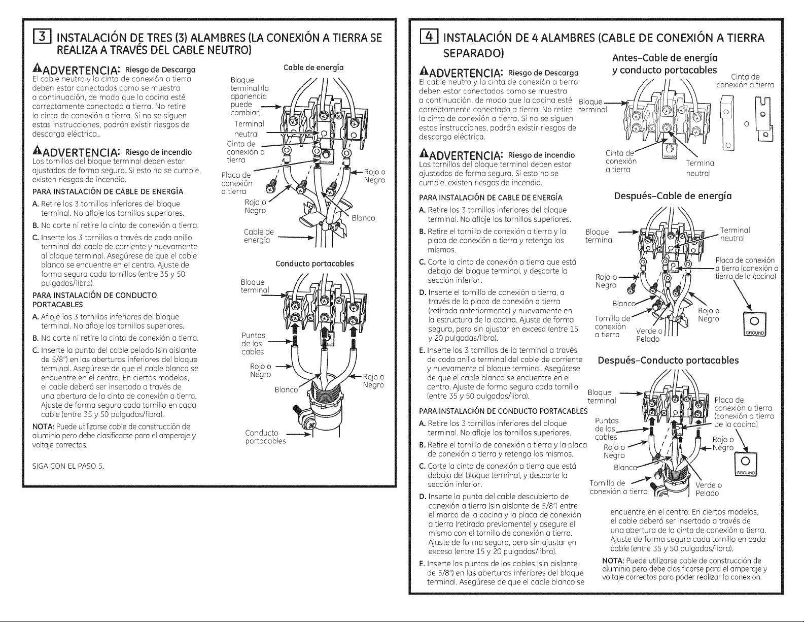
[i] INSTALACI6N DE TRES (3) ALAMBRES (LA CONE×I6N A TIERRA SE
REALIZA A TRAVES DEL CABLE NEUTRO)
A
_ADVERTENCIA: Riesgo de Descarga
El cable neutro y la cinta de cone×i6n a tierra Bloque
deben estar conectados coma se muestra terminal (la
a continuaci6n, de modo que la cocina est6 apariencia
correctamente conectada a tierra. No retire puede
la cinta de cone×i6n a tierra. Si no se siguen cambiar)
estas instrucciones, podr6n e×istir riesgos de Terminal
descarga el6ctrica., neutral
A
_ADVERTENCIA: Riesgo de incendio
Los tornillos del bloque terminal deben estar
ajustados de forma segura. Siesto no se cumple,
existen riesgos de incendio.
PARA INSTALACION DE CABLEDE ENERGiA
A. Retire los ] tornillos inferiores del bloque
terminal. No afioje los tornillos superiores.
B. No carte ni retire la cinta de cone×i6n a tierra.
C. Inserte los ] tornillos a trav6s de cada anillo
terminal del cable de corriente y nuevamente
al bloque terminal. AsegOrese de que el cable
blanco se encuentre en el centro. Ajuste de
forma segura cada tornillos (entre ]S y SO
pulgadas/libra).
PARA INSTALACION DE CONDUCTO
PORTACABLES
A. Afioje los ] tornillos inferiores del bloque
terminal. No afloje los tornillos supedores.
B. No carte ni retire la cinta de cone×i6n a tierra.
C. Inserte la punta del cable pelado (sin aislante
de 5/8") en las aberturas inferiores del bloque
terminal. Aseg0rese de que el cable blanco se
encuentre en el centro. En ciertos modelos,
el cable deber6 ser insertado a trav@sde
una abertura de la cinta de cone×i6n a tierra.
Ajuste de forma segura cada tornillo en cada
cable (entre S5y 50 pulgadas/libra).
NOTA: Puede utilizarse cable de construcd6n de
aluminio pero debedasificarse para elamperaje y
voltaje correctos.
SIGA CON EL PASO 5.
Cinta de
cone×i6n a
tierra
Placa de
cone×i6n
a tierra
Rojo
Negro
Cable de
energia
BIoque //_ Mh\
termi
Puntas _ l!_| []-
de los ---'_ _
Ro;oo- \ II //
Negro "__._-t_ _./-_r-- Rojo o
Conducto --_1 --- I
portacables
Cable de energia
Negro
Blanco
Conducto portacables
t/ FI n
. Blanco_ Negro
[TI INSTALACI6N DE 4 ALAMBRES (CABLE DE CONE×I6N A TIERRA
SEPARADO) Antes-Cable de energia
AADVERTENCIA: Riesgo de Descarga y conducto portacables Cinta de
deben estar conectados coma se muestra
Elcable neutro y la cinta de cone×i6n a tierra ____/
a continuaci6n, de modo que la codna est6 BIoque
correctamente conectada a tierra. No retire terminal It_i_ti _
la cinta de cone×i6n a tierra. Si no se siguen
estas instrucdones, podr6n e×istir riesgos de '__
descarga el6ctrica.
AADVERTENCIA: Riesgode incendio
Los tornillos del bloque terminal deben estar cone×ion
ajustados de forma segura. Siesto no se a tierra
cumple, e×isten riesgos de incendio.
PARA INSTALACI6N DE CABLE DE ENERGIA
A. Retire los ] tornillos inferiores del bloque
terminal. No afloje los tornillos superiores.
B.Retire el tornillo de cone×i6n a tierra y la
placa de cone×i6n a tierra y retenga los
mismos.
C.Carte la cinta de cone×i6n a tierra que est6
debajo del bloque terminal, y descarte la
secei6n inferior.
D.Inserteel tornillo de cone×i6na tierra, a
trav6sde la placade cone×i6na tierra
(retiradaanteriormente)y nuevamenteen
la estructurade lacocina.Ajustede forma
segura,perosin ajustar enexceso(entreJ_s
y 20pulgadas/libra).
E.Insertelos] tornillosde laterminal atrav6s
decada anilloterminal del cabledecorriente
y nuevamentealbloqueterminal.Aseg0rese
deque el cableblancose encuentreen el
centro.Ajustedeforma seguracada tornillo
(entre]S y S0pulgadas/libra).
PARA INSTALACI6N DE CONDUCTO PORTACABLES
A. Retire los 5 tornillos inferiores del bloque Puntas
terminal. No afloje los tornillos superiores, cables
B.Retire el tornillo de conexi6n a tierra y la placa Rojo o
de conexi6n a tierra y retenga los mismos. Negro
C.Carte la dnta de conexi6n a tierra qua est6
debajo del bloque terminal, y descarte la
secci6n inferior.
D.Insertela puntadel cable descubiertode
cone×i6na tierra (sinaislantede 5/8")entre
el marco dela codna y la placade cone×i6n
atierra (retiradapreviamente)y asegureel
mismocon eltornillo de cone×i6na tierra.
Ajustede formasegura,perosin ajustaren
exceso(entre15y 20pulgadas/libra).
E.Insertelas puntasdelos cables(sinaislante
de5/8'1en lasaberturasinferioresdel bloque
terminal.Aseg0resedeque el cableblancose
Despu@s-Cable de energia
Despu@s-Conducto portacables
BIoque
terminal
de los
Tornillo de Verde o
cone×i6n a tierra Pelado
encuentre en el centro. En ciertos modelos,
el cable deber6 ser insertado a trav6s de
una abertura de la cinta de conexi6n a tierra.
Ajuste de forma segura cada tornillo en cada
cable (entre IS y SOpulgadas/libra).
NOTA: Puedeutilizarse cable de construcci6n de
aluminio pero debe clasificarse para elamperaje y
voltaje correctos para poder realizar la conexi6n.
°eiaeO
Terminal
neutral
i_Terminal
neutral
Placa de conexi6n
_a tierra (conexi6n a
tierra de la cocina)
Negro
Placa de
cone×i6n a tierra
(conexi6n a tierra
de la cocina)
Rojo
Page 15
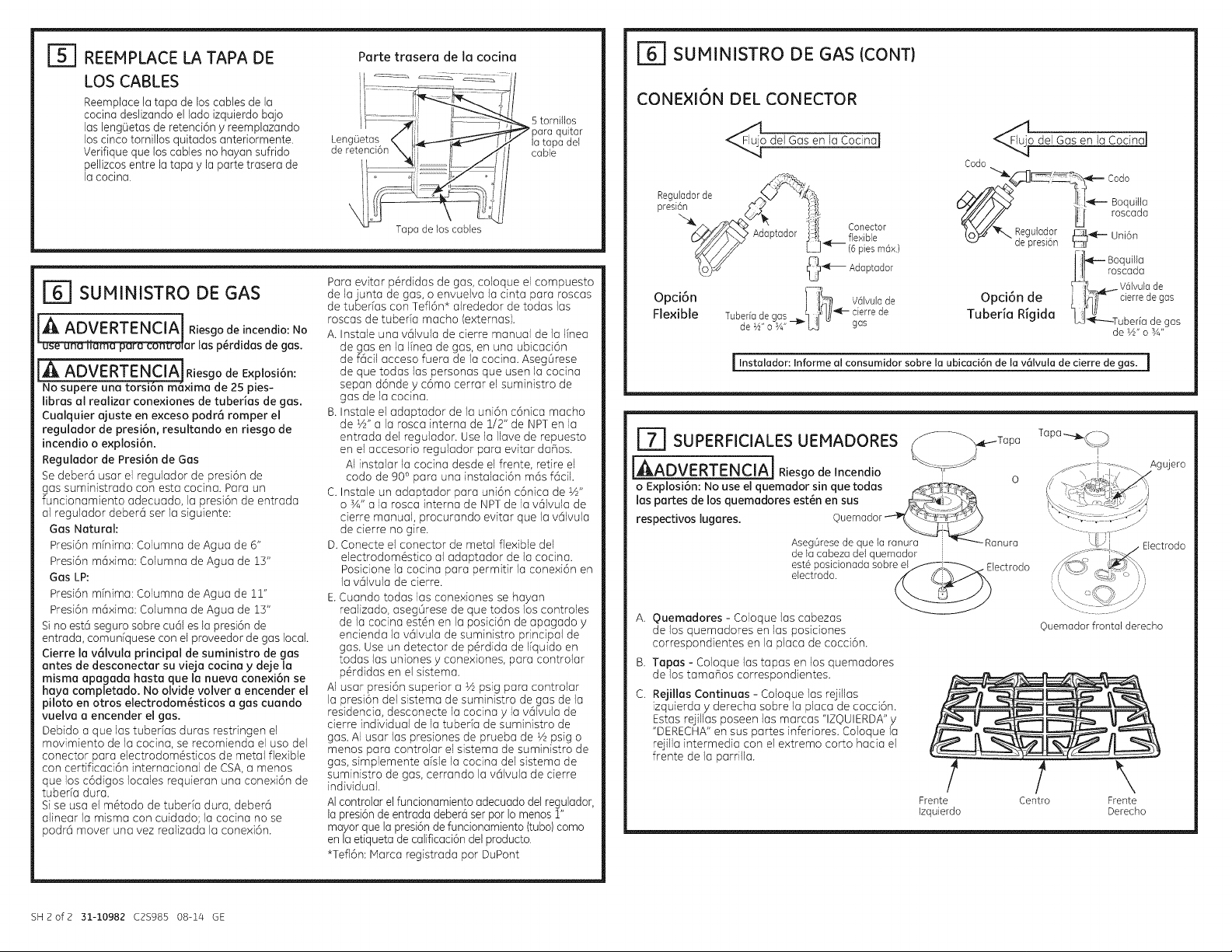
Ibl REEMPLACE LATAPA DE
LOS CABLES
Reemplace la tape de los cables de la
cocina deslizando el lado izquierdo bajo
las leng0etas de retenci6n y reemplazando
los cinco tornillos quitados anteriormente.
Verifique que los cables no hayan sufrido
pellizcos entre la tape y laparte trasera de
la cocina.
J_] SUMINISTRO DE GAS
IA ADVERTENCIAlRiesgodeincendio:No
"_ar las p_rdidas de gas.
iA ADVERTEN_ mesgode Explos,on:
No supere una torsi6n m6xima de 25 pies-
Iibras al realizar conexiones de tuberias de gas.
Cualquier ajuste en exceso podr6 romper el
regulador de presi6n, resultando en riesgo de
incendio o explosi6n.
Regulador de Presi6n de Gas
Sedeberd usar el regulador de presi6n de
gas suministrado con esta cocina. Para un
funcionamiento adecuado, la presi6n de entrada
al regulador deber6 ser la siguiente:
Gas Natural:
Presi6n minima: Columna de Agua de 6"
Presi6n m6xima: Columna de Agua de 15"
Gas LP:
Presi6n minima: Columna de Ague de 11"
Presi6n m6xima: Columna de Agua de 13"
Sino est6 seguro sobre cu61es la presi6n de
entrada, comuniquese con el proveedor de gas local.
Cierre la v61vula principal de suministro de gas
antes de desconectar su vieja cocina y deje la
misma apagada hasta que la nueva conexi6n se
haya completado. No olvide volver a encender el
piloto en otros electrodom6sticos a gas cuando
vuelva a encender el gas,
Debido a que las tubefias duras restringen el
movimiento de la cocina, se recomienda el uso del
conector para electrodom6sticos de metal flexible
con certificaci6n internacional de CSA,a menos
que los c6digos locales requieran una conexi6n de
tuberia dura.
Sise usa el m6todo de tuberia dura, deberc_
alinear la misma con cuidado; la cocina no se
podrc_mover una vez realizada la conexi6n.
Parte trasera de la cocina
5 tornillos
Leng0etas la tapa del
de retenci( cable
Tapa de los cables
Para evitar p6rdidas de gas, coloque el compuesto
de la junta de gas, o envuelva la cinta para roscas
de tuberias con Tefl6n* aJrededor de todas ias
roscas de tuberfa macho (extemas).
A. Instale una v6lvula de cierre manual de la linea
de gas en la linea de gas, en una ubicaci6n
de f6cil acceso fuera de la cocina. Aseg0rese
de que todas las personas que usen la cocina
sepan d6nde y c6mo cerrar el suministro de
gas de la cocina.
B. Instale el adaptador de la uni6n c6nica macho
de W' a la rosca intema de 1/2" de NPTen la
entrada del regulador. Use la Ilave de repuesto
en el accesorio regulador para evitar daflos.
AI instalar la cocina desde el frente, retire el
codo de 900para una instalaci6n m6s f6cil.
C. Instale un adaptador para uni6n c6nica de W'
o sA" a la rosca interna de NPTde la v61vula de
derre manual, procurando evitar qua la v61vula
de cierre no gire.
D. Conecte el conector de metal flexible del
electrodom6stico aJadaptador de la cocina.
Posicione la cocina para permitir la conexi6n en
la v6Jvula de cierre.
E.Cuando todas las conexiones se hayan
realizado, aseg0rese de qua todos los controles
de Ja cocina est6n en la posici6n de apagado y
encienda la v61vula de suministro principal de
gas. Use un detector de p6rdida de Ifquido en
todas las uniones y conexiones, para controlar
p6rdidas en el sistema.
AI usar presi6n superior a Vzpsig para controlar
la presi6n del sistema de suministro de gas de la
residencia, desconecte la cocina y la v61vula de
derre individual de la tuberfa de suministro de
gas. AIuser las presiones de prueba de Vzpsig o
menos para controlar el sistema de suministro de
gas, simplemente dsle la cocina del sistema de
suministro de gas, cerrando la v61vula de cierre
individual.
AIcontrolar el funcionamiento adecuado delregulador,
la presi6nde entrada debeM ser par Iomenos 1"
mayor que la presi6n defuncionamiento (tuba)como
en la etiqueta decalificaci6n del producto.
*Tefl6n: Marca registrada por DuPont
quitar
[_ SUMINISTRO DE GAS (CONT)
CONEXI6N DEL CONECTOR
ode] Gas en laCocinaJ
_._ujo del Gas en la Cocina]
Codo
Reg<adorde
preslon ) { ]!!
"_m ,/7Y,'04_k/_ . , 1,i[ Conector
6_//b_'9 Adap_oaorl%__fle×ible
_¢ 0_ Adaptador
Opci6n
Flexible
I Instalador: Informe al consumidor sobre la ubicaci6n de la v61vuta de cierre de gas. I
[^1E_ SUPERFICIALESU EMADORES q_._f_r_Tap a
[,_ADVERTENCIA_ Riesgo de Incendio i o
o Explosi6n: No use el quemador sin que todas x___j'_¢_.
las partes de los quemadores est6n en sus
respectivos lugares. Ouemador
A. Ouemadores - Coloque las cabezas
de los quemadores en las posidones
correspondientes en laplaca de cocd6n.
B. Tapes - Coloque las tapas en los quemadores
de los tamaflos correspondientes.
C. Rejillas Continuas- Coloque los rejillas
izquierda y derecha sobre la place de cocci6n.
Estas rejillas poseen las marcas "IZ©UIERDA"y
"DERECHA"en sus partes inferiores. Coloque la
rejilla intermedia con el extremo corto hacia el
frente de la parrilla.
AsegOresedeque la ranura Ranura
dela cabezadelquemador
est6posicionadasobreel i Electrodo
electrodo.
_._/// JJl roscada
Opci6n de ; !,_]F cierredegas
Tuberia Rigida _"_-----Tuberfa degas
Frente
Izquierdo
7-c.o
Ta pa -.-..._f %,
©uemador frontal derecho
Boquiiia
t_ Boquille
J_L, roscada
_-iL..,_- V_lvulade
deW,o sA,,
I
\
Centro Frente
Derecho
SH2of2 31-10982 C2S985 08-14 GE
Page 16
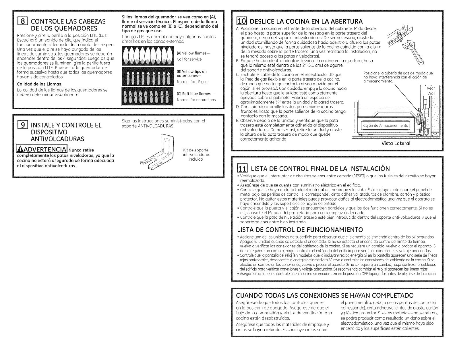
181 CONTROLE LAS CABEZAS
DE LOS QUEMADORES
Presione y gire la perilla a la posici6n LITE(Luz).
Escuchar6 un sonido de cNc,qua indica el
funcionamiento adecuado de1m6dulo de chispeo.
Una vez qua el aire se haya purgado de las
Ifneas de suministro, los quemadores se deber6n
encender dentro de los 4 segundos. Luego de qua
los quemadores se iluminen, gire la perilla fuera
de la posid6n LITE. Pruebe cada quemador de
forma sucesiva hasta que todos los quemadores
hayan sido controlados.
Calidad de las Llamas
La calidad de las llamas de los quemadores se
debar6 determinar visualmente.
r_ INSTALE V CONTROLE EL
DISPOSITIVO
ANTIVOLCADURAS
iAADVERTENCIAjNunca retire
completamente los patas niveladoras, ya que la
cocina no estara asegurada de forma adecuada
al dispasitivo antivolcaduras,
Si las llamas del quemador se ven como en {A),
flame al servicio t_cnico. El aspecto de la llama
normal se ve como en {B) o {C), dependiendo del
tipo de gas que use.
Con gas LP,es normal que haya algunas puntas
amarillas en los COHOSexternos.
(A)Yellow flames-
Call for service
(B)Yellow tips on
outercones--
Normal for LPgas
(C)Soft blue flames--
Normal for natural gas
Siga los instrucciones suministradas con el
soporte ANTIVOLCADURAS.
Kit de soporte
anti-volcaduras
incluido
1101 DESLICE LA COCINA EN LA ABERTURA
A. Posicione Iacocina en el frente de la abertura del gabinete. Mida desde
el piso hasta la parte superior de la mesada en la parte trasera del
gabinete, cerca del soporte antivotcaduras. De ser necesario, ajuste Ia
unidad atornilIando de forma cuidadosa hacia adentro o afuera las paras
niveladoras, hasta que Ia parte saliente de lacocina coincida con la aItura
de la mesada sobre la parte trasera (una vez reaNzada Ia instaIaci6n, no
se tendr6 acceso a Ias paras niveladoras).
B.Empuje hacia adentro mientras Ievanta Iacocina en la apertura, hasta
que Ia misma est@dentro de Ias2" (5.1cm.) de agarre
del soporte antivolcaduras.
C. Enchufe el cable de la cocina en elrecept6culo. Ubique
la linea de gas flexible en la parte trasera de lacocina,
de modo que no tenga contacto ni sea movida por el
caj6n (sies provisto). Con cuidado, empuje lacocina hacia
la abertura hasta que la unidad est_ completamente
apoyada sobre elgabinete. Habr6 un espacio de
aproximadamente 1A"entre la unidad y la pared trasera.
D.Con cuidado atorni% Ias dos paras niveleadoras
frontales hasta que la parte saliente de Iacocina tenga
contacto con la mesada.
E.Observe debajo de la unidad y verifique que Ia pata
trasera est@completamente adherida al dispositivo
antivolcaduras. Deno ser as[,retire Ia unidad y ajuste
Ia altura de la pata trasera de modo que quede
correctamente adherida.
posicionelatuberfade gas demodo que
nohaya interferenciaconelcaj6n de
almacenamiento.
1/11111/11/!/11111/1//1111111/1!111/1111/1111, I//I/!111_
Vista Lateral
Tt=
r-mill1LISTA DE CONTROL FINAL DE LA INSTALACI6N
• Verifique que el interruptor de circuitos se encuentre cerrado (RESET)o que los fusibles del circuito se hayan
reemplazado.
AsegOresede que se cuentecon suministro el@ctricoen el edificio.
Controle que se haya quitado todo etmaterial de empaque y iacinta. Esto incluye cinta sobre el panel de
metal bajo las perillas de control (sicorresponde), cinta adhesiva, ataduras de alambre, cart6n ypl6stico
protector. No quitar estos materiales puede provocar dahos al electrodom@sticouna vez que elaparato se
haya encendidoy las superficies sehayan calentado.
Controle qua la puerta y el caj6n seencuentren paralelos y que losdos funcionen correctamente. Sino es
as[,consulte el Manual del propietario para un reemplazo adecuado.
Controle que la pata de nivelaci6n trasera est_ bienintroducida dentro del soporte anti-volcaduras y que el
soporte seencuentre bien instolado.
LISTA DE CONTROL DE FUNCIONAMIENTO
•Accioneunade losunidadesde superficieporaobservarqueel etementoseencienda dentro delos60 segundos.
Apague la unidadcuandose detecteel encendido.Sino se detectael encendidodentro del limitedetiempo,
vuetvaa verificarlosconexionesdel cableadodela cocina.Sise requiereuncambio, vuelvaa probarel aparato. Si
nose requiereun cambio,haga controtarel cableadodel edificioparaverificar conexionesy voltajeadecuados.
• Controtequela pantalladelretoj(enmodelosque Ioincluyan)recibaenergia.Sienlapantallaaparecenuna seriedelineas
rojashorizontales,desconectelaenergiadeinmediato.Vuelvaacontrolarlasconexionesdelcabteadodelacocina.Sise
efectOauncambioen losconexiones,vuelvaaprobarel aparato.Sinoserequiereuncambio,hagacontrotarel cableado
deledificioparaverificarconexionesyvoltajeadecuados.Serecomiendacambiarelrelojsiaparecenloslineasrojas.
• AsegOresedeque loscontrolesde lacocinaseencuentrenenla posici6nOFF(apagado)antesdealejarsedela cocina.
CUANDO TODAS LAS CONE×IONES SE HAYAN COIPLETADO
AsegOrese de que todos los controles queden el panel met61icodebajo de las periNasde control (si
en la posici6n de apagado. AsegOrese de que el corresponde), cinta adhesiva, cintas de ajuste, cart6n
flujo de la combusti6n y el aire de ventilaci6n a la y pl6stico protector. Siestos materiales no se retiran,
codna est6n desobstruidos, se podr6 producir como resultado un daho sobre el
Aseg6rese qua todos los materiales de empaque y electrodom_stico, una vezqua el mismo hayo sido
cintas se hoyon retirodo. Estoincluye cintas sobre encendido y los superficies est@ncoNentes.
 Loading...