

Page 1
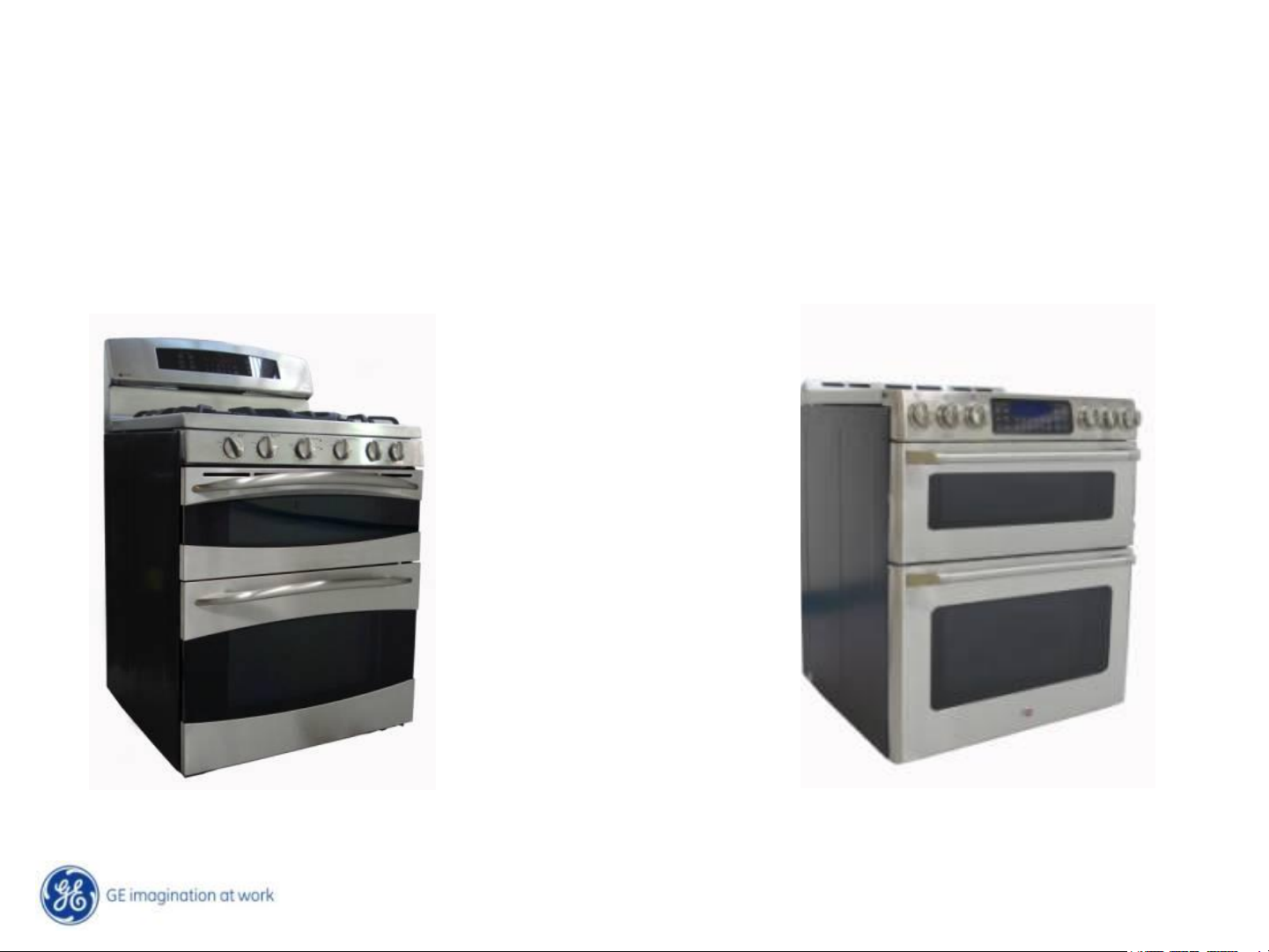
Dual Cavity Gas, Free Standing Ranges
Café, Profile & GE
JGB870DET
JGB870SET
PGB900DET
PGB900SET
PGB910DET
PGB910SET
PGB915SET
PGB930DET
PGB930SET
PGB935SET
P2B930DET
P2B930SET
PGB980SET
PGB995DET
PGB995SET
CGS990SET
CGS985SET
Café Profile & GE
C2S985SET
Copyright General Electric 2011
Page 2

IMPORTANT SAFETY NOTICE
The information in this presentation is intended for use by individuals
possessing adequate backgrounds of electrical, electronic, &
mechanical experience. Any attempt to repair a major appliance may
result in personal injury & property damage. The manufacturer or seller
cannot be responsible for the interpretation of this information, nor can it
assume any liability in connection with its use.
WARNING
To avoid personal injury, disconnect power before servicing this product.
If electrical power is required for diagnosis or test purposes, disconnect
the power immediately after performing the necessary checks.
RECONNECT ALL GROUNDING DEVICES
If grounding wires, screws, straps, clips, nuts, or washers used to
complete a path to ground are removed for service, they must be
returned to their original position & properly fastened.
Page 3
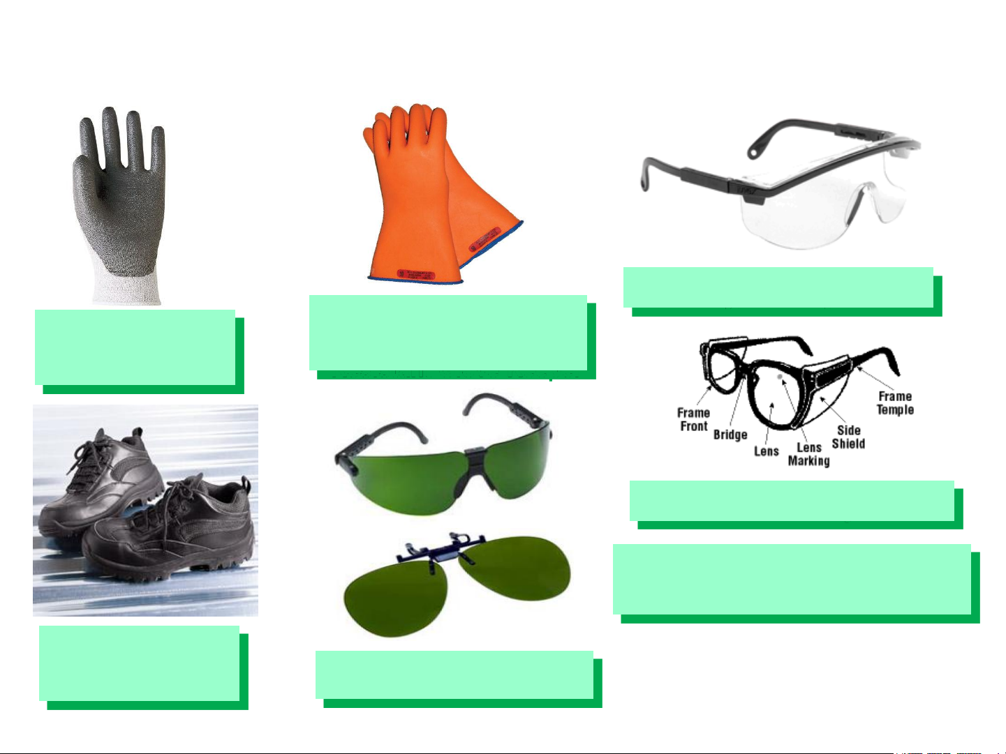
GE Factory Service Employees are required to use safety glasses with
side shields, safety gloves & steel toe shoes for all repairs.
Plano Type Safety Glasses
Electrically Rated Glove
Dyneema® Cut
Resistant Glove
Steel Toe Work
Boot
and Dyneema® Cut
Resistant Glove Keeper
Prescription Safety Glasses
Safety Glasses must be
ANSI Z87.1-2003 compliant
Brazing Glasses
Page 4
Copyright General Electric 2011
11/28/2011
4 /
Page 5
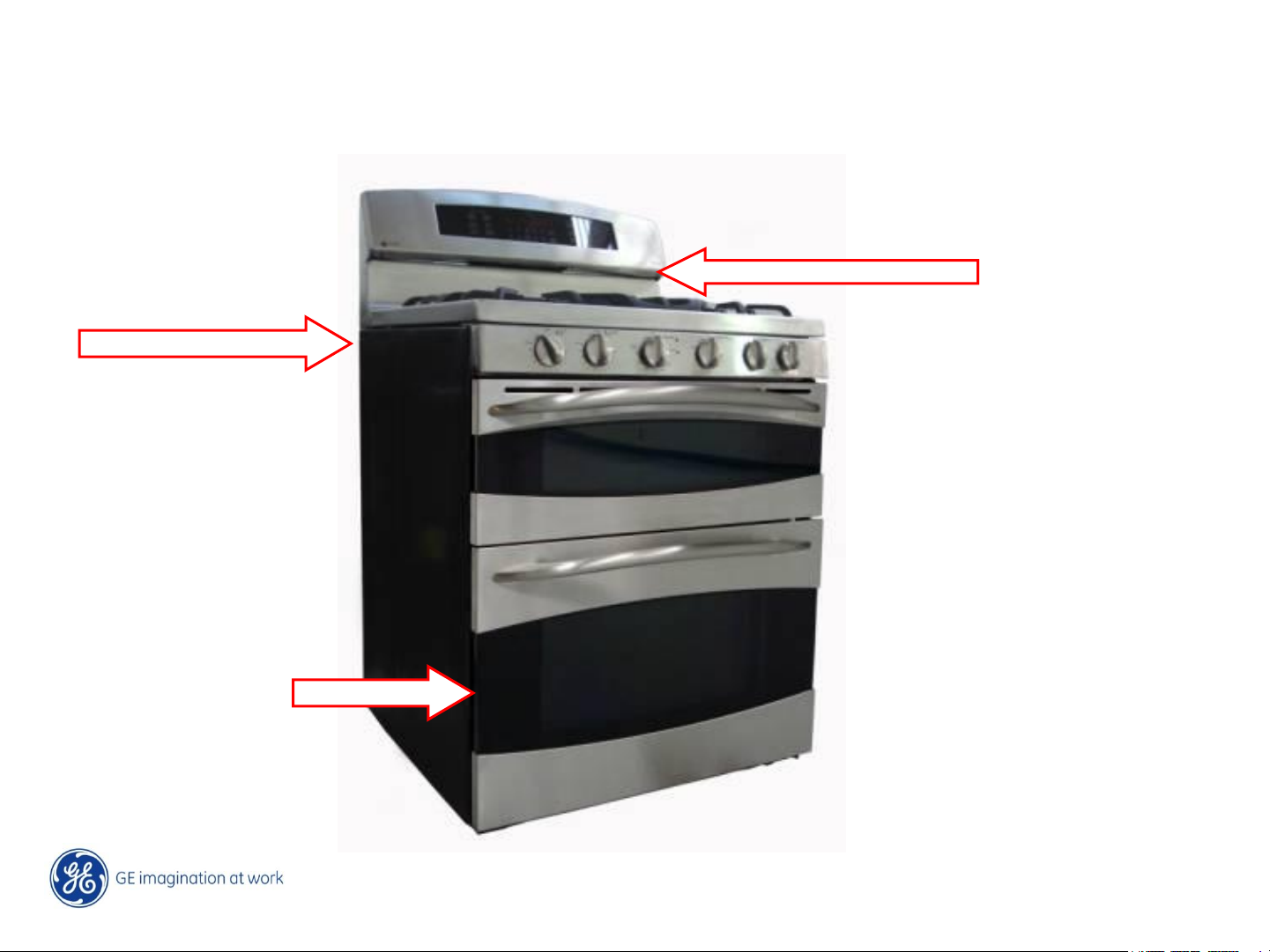
The Mini Manual is located in the control panel area on GE & Profile units. Back top left
rear corner on Café models.
The Nomenclature Tag is on the bottom left side front frame of the main oven.
Mini Manual Profile & GE
Mini Manual Cafe
Model Tag
Copyright General Electric 2011
5 /
11/28/2011
Page 6
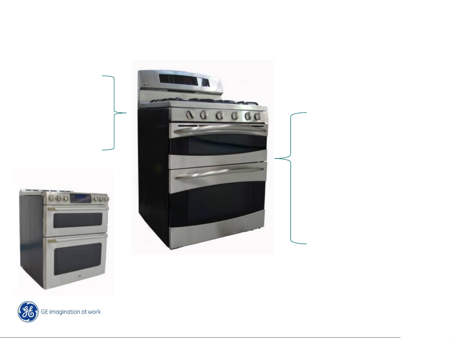
Overview-Product Info
Café, Profile, and GE Brands
Cooktop
•Tri-Ring Burner
•Tri-Bridge Burner
•Tri-Bridge Griddle
Double Oven
• Upper Oven 2.5 cuft
• Lower Oven 4.0 cuft
• Both Self Clean
2x Lighting
Full Visibility Door (Glass
Liner)
Black Enameled Cavity
New Doors & SS trims
Copyright General Electric 2011
11/28/2011
6 /
Page 7
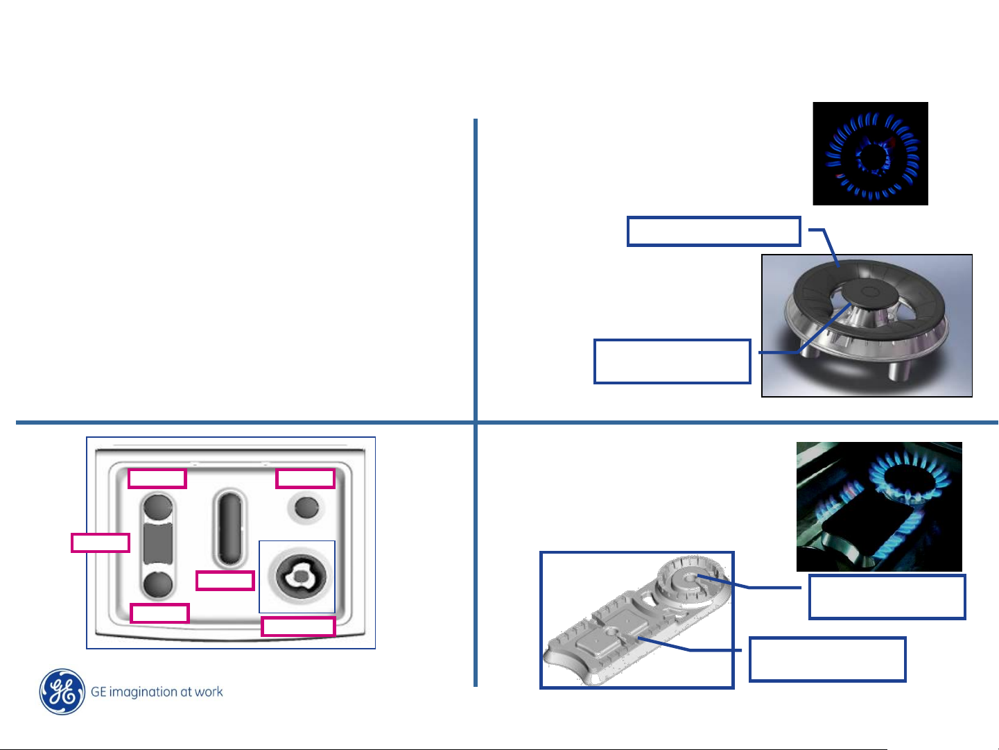
Overview-Feature Detail
Cooktop Burners
3 Ring = 19/20K BTUs
• Tri Ring 20K BTUs- Café / 19K Profile
• Tri Bridge 23K BTUs
• New cooktop configurations
• New Griddles / Double-Bridge Griddle
9.1K
5.0K
9.5K
9.1K
5.0K
20/19K
17000 btu/h Max.
3000 btu/h Max.
400 btu/h Min.
3 Bridge = 24K BTUs
5000 btu/h Max.
1000 btu/h Min.
9100 btu/h Max.
850 btu/h Min.
Copyright General Electric 2011
11/28/2011
7 /
Page 8
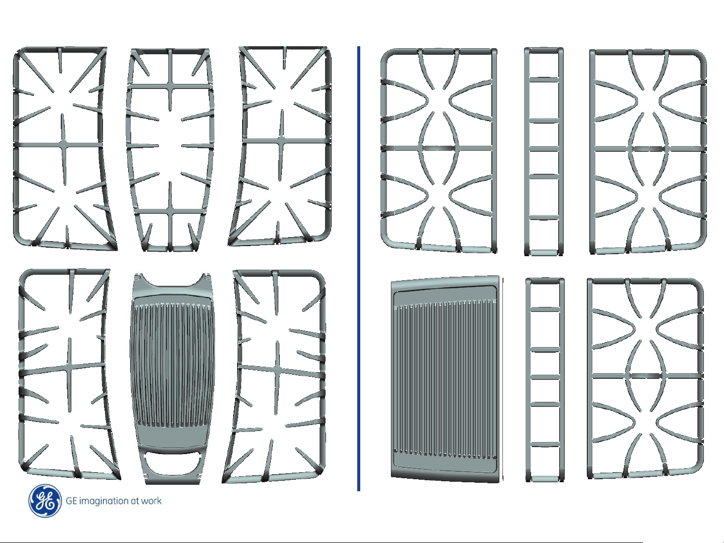
Cooktop Grates & Griddle Designs
Copyright General Electric 2011
11/28/2011
8 /
Page 9
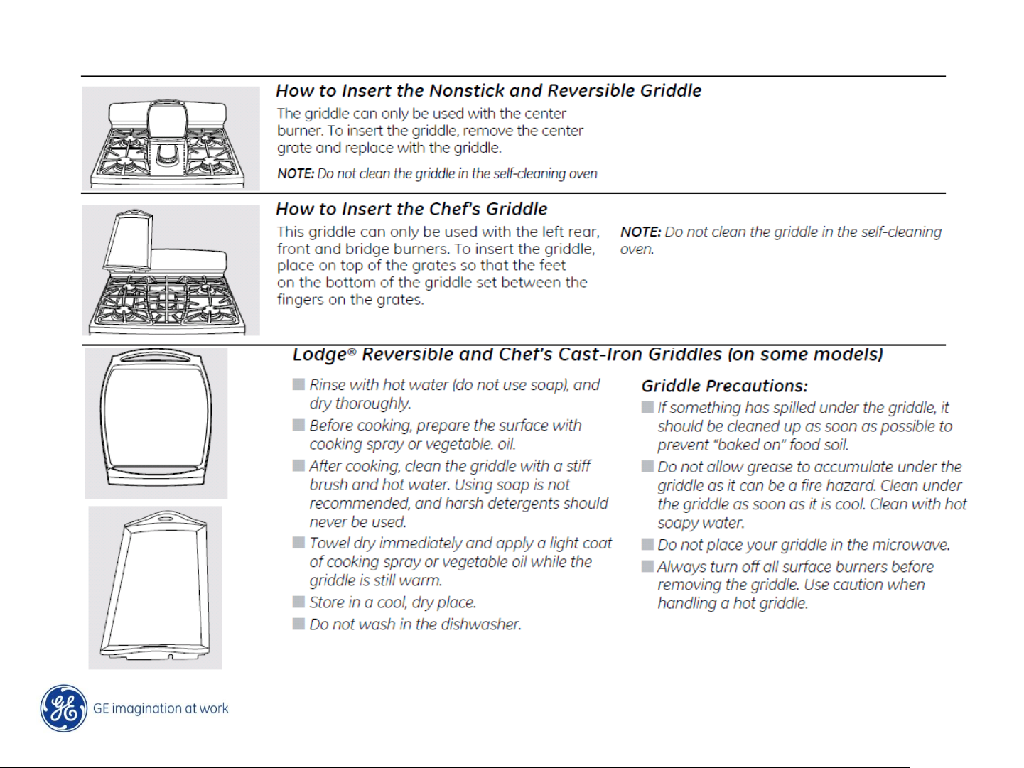
Note: The center griddle is used without the center grate installed, the Chef griddle is
installed on top of the left grate.
Copyright General Electric 2011
11/28/2011
9 /
Page 10
Copyright General Electric 2011
11/28/2011
10 /
Page 11
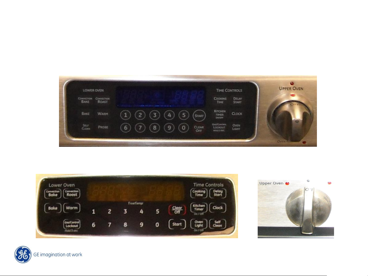
Control Overview, ERC & Thermostat
The lower oven is controlled by an (ERC) electronic control, the upper oven is controlled by
an hydraulic thermostat. Both upper and lower ovens have self clean capability.
Café Models
Profile & GE Models
Copyright General Electric 2011
11 /
11/28/2011
Page 12
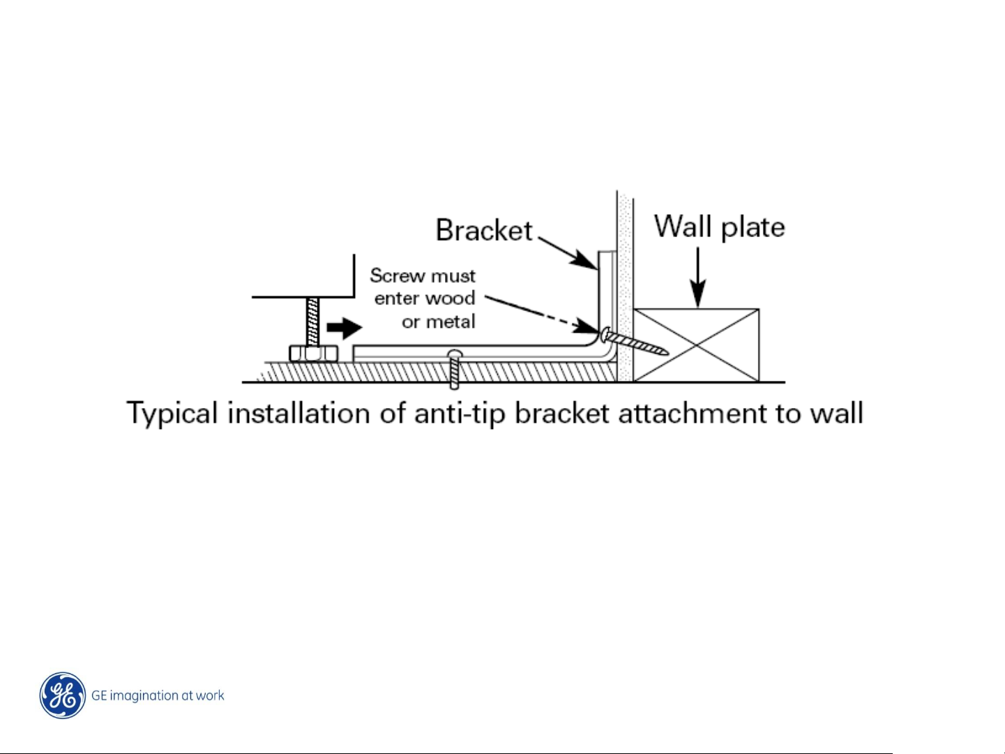
Anti-Tip Bracket
• Range must be secured by the Anti-Tip Bracket supplied.
Copyright General Electric 2011
12 /
11/28/2011
Page 13
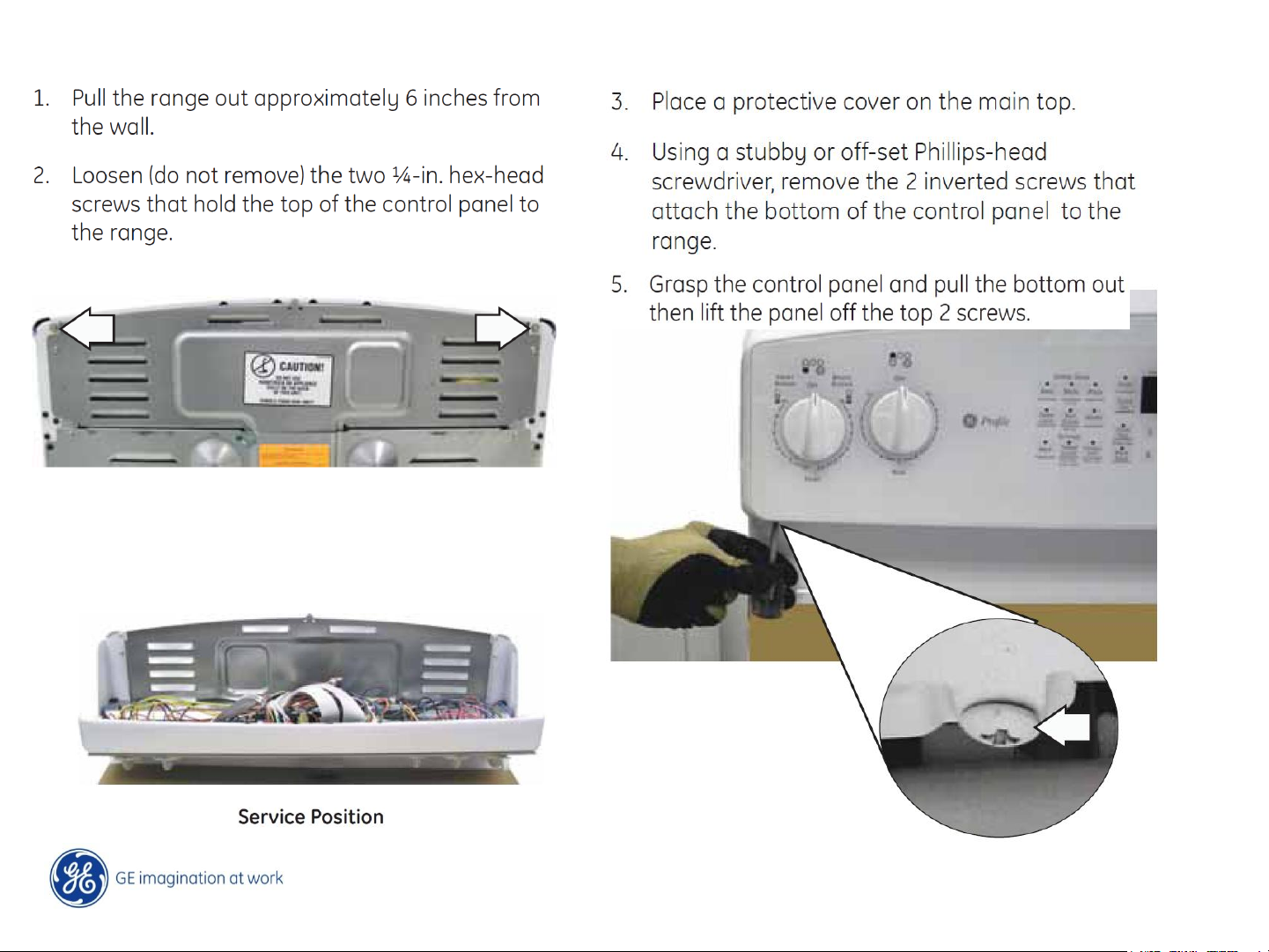
Control Panel Removal – GE & Profile
Copyright General Electric 2011
11/28/2011
13 /
Page 14

Lower Oven Door Removal
Copyright General Electric 2011
11/28/2011
14 /
Page 15
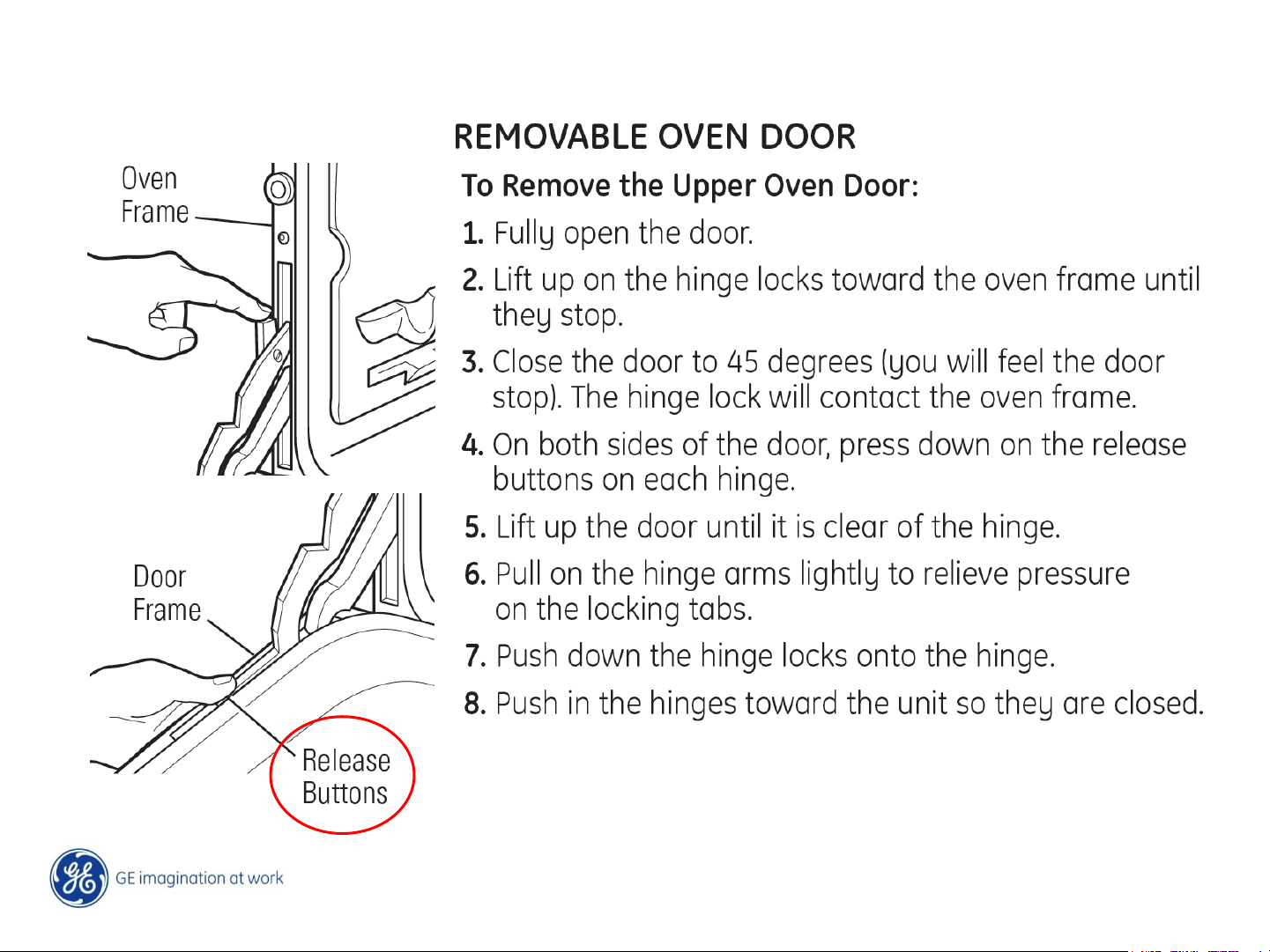
Upper Oven Door Removal – Hinge Release
Copyright General Electric 2011
11/28/2011
15 /
Page 16
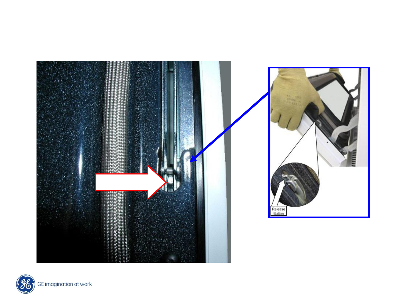
Upper Oven Door Removal
Open the oven door to a 45 degree angle from the oven frame, press in on both release
buttons and lift the door off of the door hinges.
Release Button
Copyright General Electric 2011
16 /
11/28/2011
Page 17
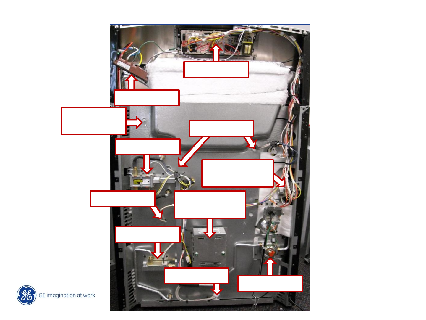
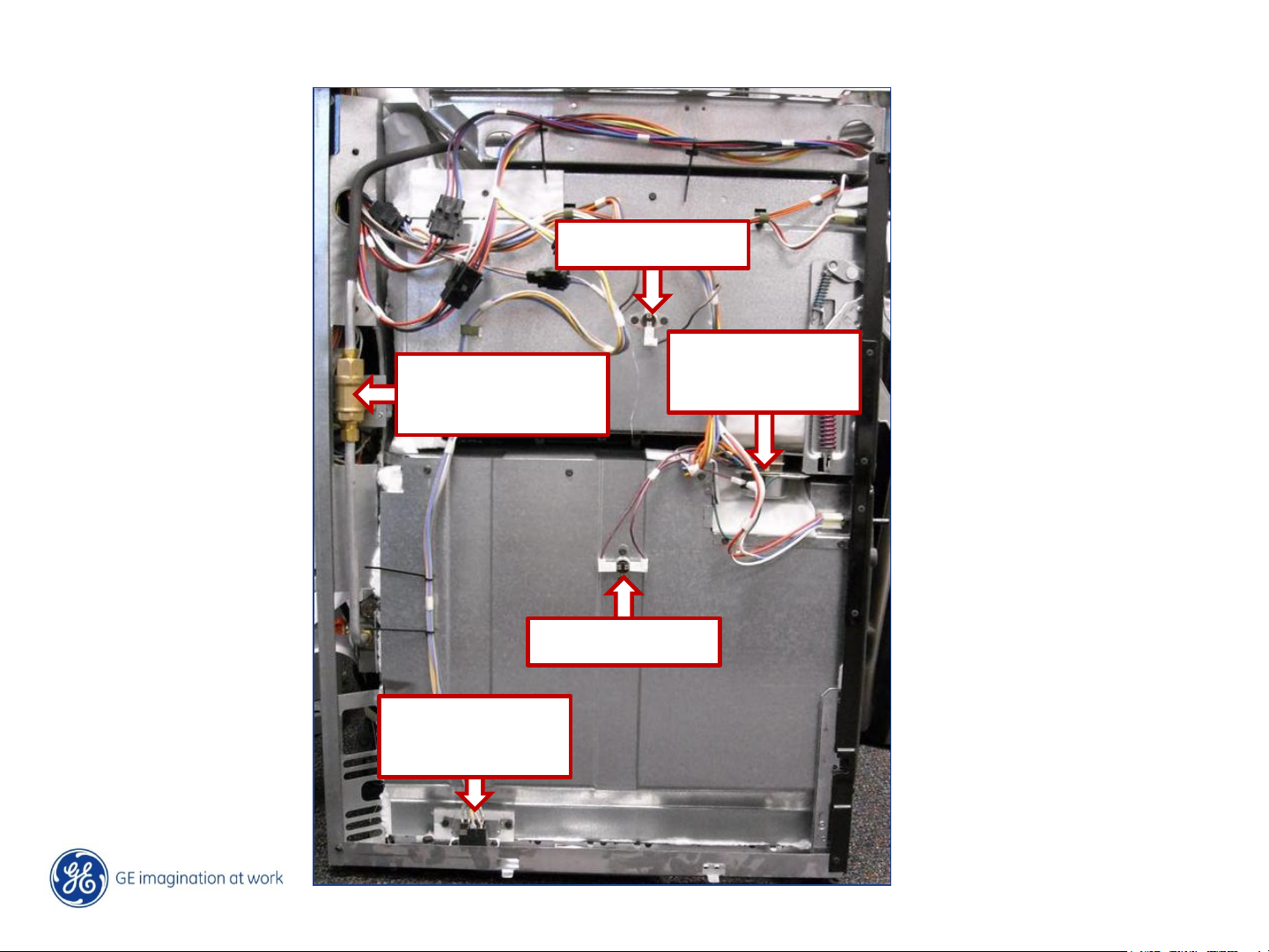
Component View, Back – Profile & GE
ERC
Spark Module
Thermostat
Capillary
Oven Sensor
Igniters UO
Gas Valve UO
Gas Lockout
Valve
Convection
Fan Motor
Gas Valve LO
Igniter LO
Regulator
17 /
Copyright General Electric 2011
11/28/2011
Page 18
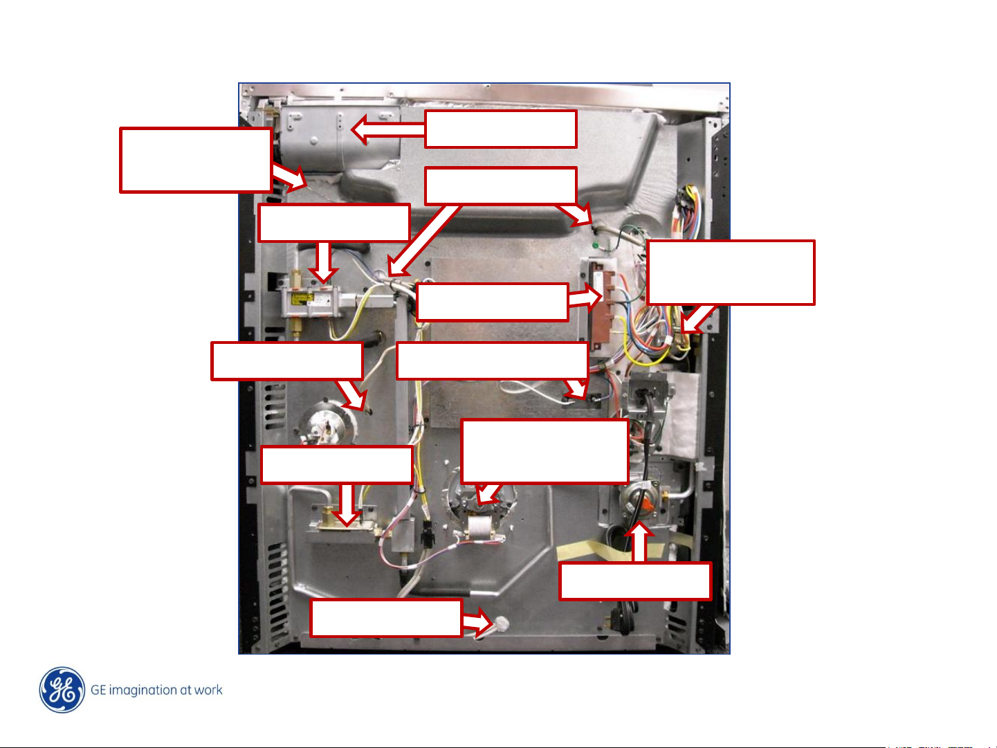
Component View, Back – Café
Thermostat
Cooling Fan
Capillary
Oven Sensor
Gas Valve UO
Gas Valve LO
Igniters UO
Gas Lockout
Valve
Spark Module
Broil Element LO
Convection
Fan Motor
Igniter LO
Regulator
18 /
Copyright General Electric 2011
11/28/2011
Page 19
Component View, LH Side – All Models
TCO UO
Gas Lockout
Valve
Self Clean
Latch Assy
Lock Out
Relay UO
TCO LO
19 /
Copyright General Electric 2011
11/28/2011
Page 20
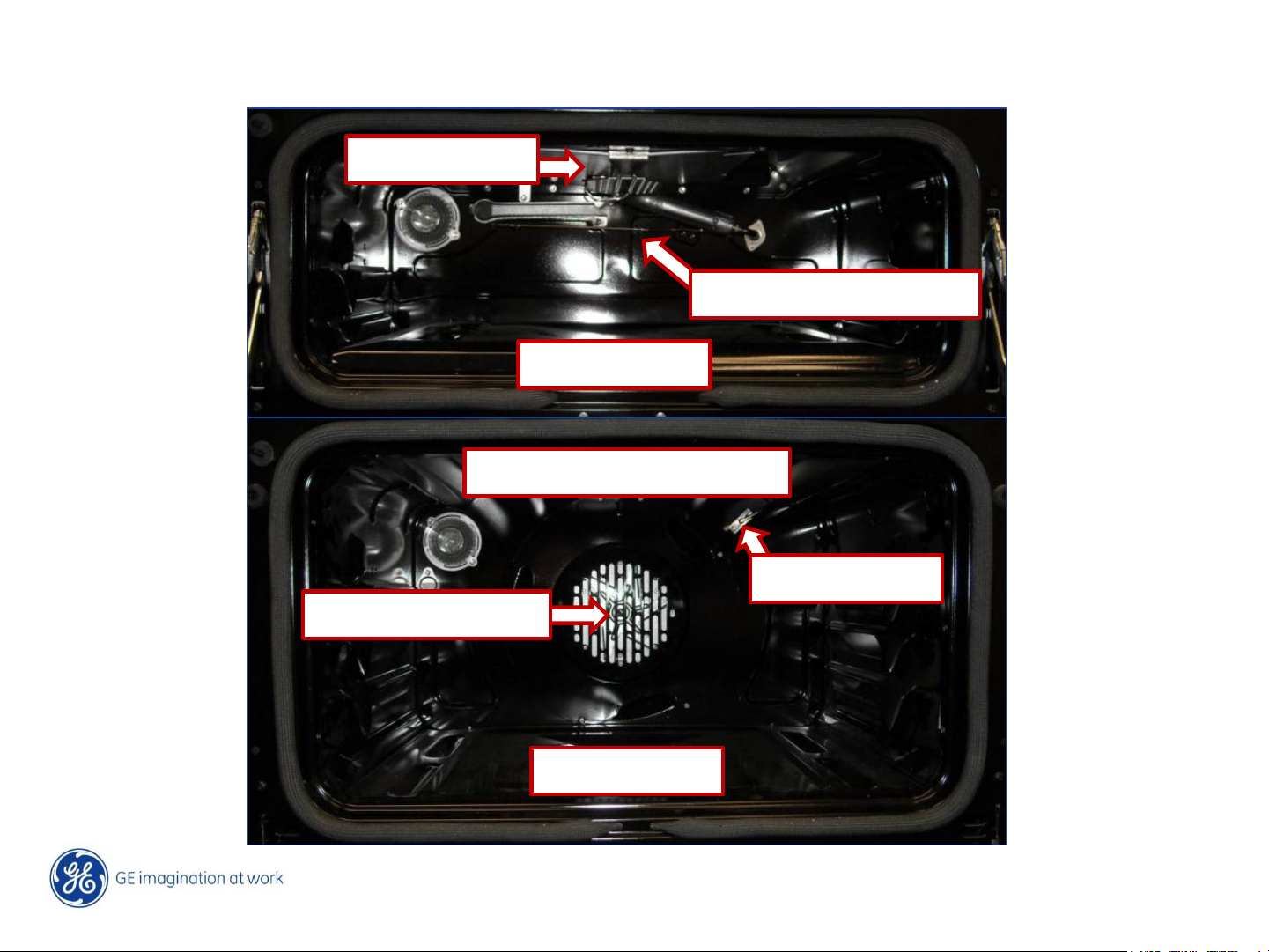
Component View, Oven Cavities
Broil Burner
Thermostat Capillary
Bake Burner
Broil Element, Café Only
Convection Fan
Sensor
Bake Burner
20 /
Copyright General Electric 2011
11/28/2011
Page 21
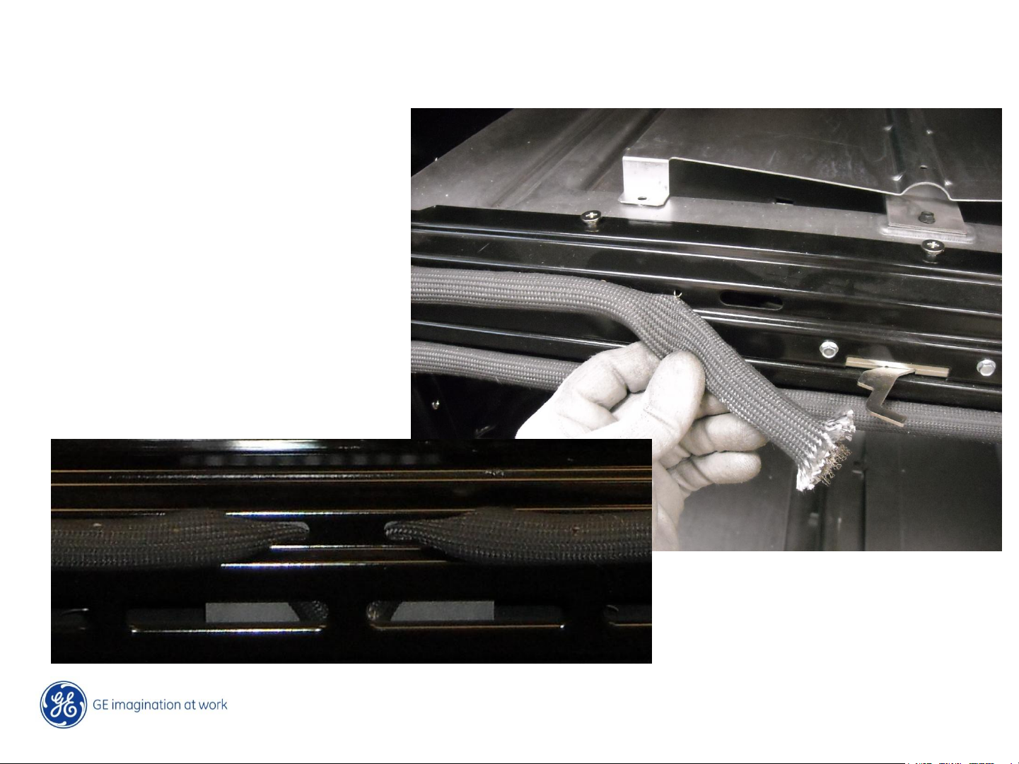
Oven Gaskets
The oven gaskets are installed with push in spring clips.
The bottom corners of the gasket
are installed in two oval slots at
the bottom without a crossover.
Copyright General Electric 2011
11/28/2011
21 /
Page 22

Cooktop Removal, GE & Profile
Copyright General Electric 2011
11/28/2011
22 /
Page 23

Cooktop Removal, Café
The first step for removal of the cooktop is to remove the oven vent trim. Remove three
¼” hex head screws from the vent trim and lift for removal.
Copyright General Electric 2011
11/28/2011
23 /
Page 24

Cooktop Removal, Café
Remove all of the T-15 Torx screws from the burners and front of the cooktop. Remove
the hex screws from the back of the cooktop and remove the spark electrodes from the
burners. Lift the cooktop off of the top of the oven.
Copyright General Electric 2011
11/28/2011
24 /
Page 25

Power Boil Tri-Burner
The right front burner is a 4 orifice power burner. Café„ models are 20K btu‟s and the GE
& Profile models are rated at 19K btu‟s. The outer three orifices are all connected to a
common manifold and operate at the same time. The center orifice is the simmer
burner.
Copyright General Electric 2011
11/28/2011
25 /
Page 26

Power Boil Tri-Burner
The front orifice is de-rated for requirements for clothing ignition. The front flames will
be smaller than the other two burner orifices, this is normal for this type of burner.
Smaller burner flame
Copyright General Electric 2011
26 /
11/28/2011
Page 27

Power Boil Tri-Burner – Spark Igniter
To replace the Tri-Burner spark igniter requires removal of the cooktop. Remove the T-15
Torx from the igniter bracket to remove. The orifice does not need removal.
Copyright General Electric 2011
11/28/2011
27 /
Page 28

Self Clean Latch, Upper Oven – Profile & GE
The upper oven self clean latch is accessible after removing the cooktop. The latch is
held to the front frame by two ¼” hex head screws.
Copyright General Electric 2011
11/28/2011
28 /
Page 29

Self Clean Latch, Upper Oven – Café
On Café models there are additional heat barriers that need to be removed to access the
self clean latch. The first heat shield is held by two ¼ hex screws at the rear. Next a fiber
barrier needs to be pulled to the rear of the range to expose another cover over the latch
assembly.
Copyright General Electric 2011
11/28/2011
29 /
Page 30

ERC (Electronic Range Control – Café
On Café models there is limited access to the ERC for electrical testing with a VOM.
Copyright General Electric 2011
11/28/2011
30 /
Page 31

ERC (Electronic Range Control) – Café
Once the burner bracket manifold screws are removed, remove two additional Phillips
screws at the top rear of the control housing. The control housing can the be lifted for
better access to the ERC terminals for testing.
Copyright General Electric 2011
11/28/2011
31 /
Page 32

Upper Oven (DRT) Thermostat
To replace the upper oven thermostat requires removal of the cooktop. Once the cooktop
is removed – remove the two T-15 Torx screws holding the thermostat to the control
panel. The thermostat can then be pulled out from the control panel.
Copyright General Electric 2011
11/28/2011
32 /
Page 33

Upper Oven (DRT) Thermostat
The front of the thermostat contains a switch; this switch is an input to the ERC control.
This input provides (on or off) information to the ERC so the ERC can control the Upper
Oven Lockout Control. This also provides the ERC the ability to control the hydraulic
thermostat Self Clean timing of 5 hours. This switch closes when the thermostat is off
and opens when the thermostat is in any on position. If the switch does not open the
ERC will not allow self clean.
Copyright General Electric 2011
11/28/2011
33 /
Page 34

Upper Oven (DRT) Thermostat
The thermostat capillary routing on GE & Profile units runs through an opening behind
the right rear surface burner. On Café units the capillary routing is in the right hand
side panel. The side panel does not need to be removed for thermostat replacement,
the rear panel does need removal for the oven cavity routing.
Profile & GE
Cafe‟
34 /
Copyright General Electric 2011
11/28/2011
Page 35

Upper Oven (DRT) Thermostat
The capillary tube routes into the back panel and passes through to the upper oven
cavity where it is secured to the back wall with two spring clips.
Copyright General Electric 2011
11/28/2011
35 /
Page 36

Upper Oven (DRT) Thermostat
The DRT is a hydraulic control thermostat. It receives L1 power from a jumper at the
ERC L1. Line power is sent through the RX to SX wire contact and then through the
External relay contact. The cycling contact is on the YX to VX wires. The VX to OX is
closed for bake and VX to NX for broil.
Copyright General Electric 2011
11/28/2011
36 /
Page 37

Cooktop Burner Gas Valves
The cooktop burner valves are secured to the manifold pipe with a (saddle) clamp with a
single screw for removal. The spark module switches are “D” keyed on the valve shaft.
Clamp
Gasket
Switch
Copyright General Electric 2011
37 /
11/28/2011
Page 38

Copyright General Electric 2011
11/28/2011
38 /
Page 39

Cooling Fan – Café Models
On Café models – there is a squirrel cage cooling fan in the right rear corner of the
cooktop. To service the fan requires removal of the cooktop. Once the cooktop is
removed, remove the six ¼” Hex head screws that hold the fan housing and lift up to
remove the fan assembly. The fan motor is controlled by the ERC and the oven sensor
temperature. The fan is turned on when the oven cavity temperature exceeds 300
degrees.
Copyright General Electric 2011
11/28/2011
39 /
Page 40

FAD – Café Models
On Café models with the cooling fan there is also a FAD (Fan Apparent Device). This
thermostat will disable the ovens in an over temperature issue due to a cooling fan
failure. The FAD is a self resetting thermostat that opens at 265˚F and closes at 225˚F.
If either oven is terminating Self Clean before time out, check Fan and FAD operation.
Copyright General Electric 2011
11/28/2011
40 /
Page 41

Side Panel Removal
There are several components that require the side panel to be removed. The lower oven
self clean latch, cooktop gas cutoff valve, door hinge and an upper oven lockout relay.
After removing the top and rear panel screws remove the single Phillips screw on the
cavity front.
Copyright General Electric 2011
11/28/2011
41 /
Page 42

Side Panel Removal
Carefully swing the side panel away from the range, using a large blade screw driver pry
out between the panel where it snaps onto the retainer clip while pulling out on the top
front of the side panel.
Retainer clip
Pry Outward
Copyright General Electric 2011
42 /
11/28/2011
Page 43

Lower Oven Latch
If the lower oven door should lock shut due to a latch failure, the two ¼” hex screws
can be accessed and removed by opening the upper oven door. The latch catch can the
be manipulated to release the door.
Copyright General Electric 2011
11/28/2011
43 /
Page 44

Lower Oven Latch Assembly
Lower Oven Self
Clean Latch Assy
Copyright General Electric 2011
11/28/2011
44 /
Page 45

Lower Oven Latch Removal
The latch is replaced through the LH side with the side panel removed.
Disconnect the wiring to the TCO and white wire
that comes from the door switch to the latch motor,
disconnect the ground wire. Remove the wire
Bundle from the wire retainers.
Pull the latch assembly back and out of the frame.
Transfer the wires one at a time from the old
latch to the replacement latch.
Copyright General Electric 2011
45 /
11/28/2011
Page 46

Upper Oven – Lockout Relay
Lock Out Relay
Upper Oven
Copyright General Electric 2011
46 /
11/28/2011
Page 47

Upper Oven Lockout Relay
The upper oven uses a lock out relay that will
disable the upper oven from operating when
the lower oven is in self clean. When the lower
oven is placed into clean the relay is activated
by the ERC disabling the upper oven
thermostat control. The ERC also uses this
relay to terminate the upper oven self clean
cycle at a preset 5 hour cycle.
Copyright General Electric 2011
11/28/2011
47 /
Page 48

Upper Oven Lockout Relay
The ERC activates the lockout relay from the “OUT WD” terminal when in clean. When
powered the relay opens the cycling contact circuit of the thermostat (NC contact). In
the Upper Oven clean cycle the ERC powers the thermostat through the MDL terminal.
Clean Cycle
Copyright General Electric 2011
11/28/2011
48 /
Page 49

Cooktop Gas Lockout Valve
Gas Lockout
Valve
Copyright General Electric 2011
11/28/2011
49 /
Page 50

Gas Lockout Valve
These models also utilize a gas lock out valve which turns the gas off to the cooktop.
This feature can be activated by the consumer through the ERC control and it is
automatically activated during self clean.
Copyright General Electric 2011
11/28/2011
50 /
Page 51

Gas Lockout Valve
The gas lockout function is activated by the ERC when selected by the consumer or
when a Self Clean cycle is activated. The Lockout valve will NOT operate if a surface
burner is in the on position. Each burner switch must be in the open (OFF) position state
to complete the gas lockout function. The ERC AUX terminal sends power down to the
surface burner switches and when ALL are closed (burners off) the lock out motor runs.
Copyright General Electric 2011
11/28/2011
51 /
Page 52

Gas Lockout Valve
The gas lockout valve incorporates two positioning switches to allow the ERC to know
the position of the lockout valve. Yellow to Orange closes when the valve is open and
allowing gas flow to the cooktop. This switch opens and Yellow to Silver close when the
valve is closed.
ERC
Loss of the Yellow to Orange contact will cause the lockout motor to run continuously
and LOC will flash in the ERC display. Loss of the Yellow to Silver will cause the lockout
motor to run continuously when Lock Out or Clean is selected; LOC will flash in the
display. LOC will display steady when the cooktop is locked out.
Copyright General Electric 2011
11/28/2011
52 /
Page 53

Cavity TCO‟s – All Models
Both upper and lower oven cavity TCO‟s (Thermal Cut Outs) are wired in series between
the latching motors and the ERC. If either TCO opens
during a clean cycle, the cycle will terminate and the
ERC will return to TOD (Time Of Day). If either TCO is
open at the start of a clean cycle; the ERC will beep
until the cancel button is pressed, no “F” code will be
displayed. The error code will be logged into the ERC
Memory and can be retrieved in diagnostic mode.
Both TCO‟s are rated 176˚ F open, 158˚ F close.
Copyright General Electric 2011
11/28/2011
53 /
Page 54

Self Clean Sequence of Operation
When the lower oven is placed into clean mode,
1. The gas lockout valve rotates to shut off the cooktop gas, returns signal to ERC.
2. The lower oven latch locks the door , returns signal to ERC.
3. The upper oven latch locks the door , returns signal to ERC.
4. The upper oven lockout relay is activated , returns signal to ERC.
5. The cooling fan is turned on. (Café models)
Clean time can be set from 3 to 5 hours, default is 4 hours.
When the cycle is complete,
1. The lower oven unlocks , returns signal to ERC.
2. The upper oven unlocks , returns signal to ERC.
3. The gas lockout rotates to allow gas flow to the cooktop , returns signal to ERC.
The upper oven follows the same sequence, the cycle time is fixed at 5 hours.
The spark module remains active but the burners will not light during clean.
Note: if any of these sequences fail; the ovens will NOT self clean.
Copyright General Electric 2011
11/28/2011
54 /
Page 55

Spark Module Location
The spark module on the Profile & GE models is located in the control panel.
On Café models the module is located on the back of the unit adjacent to the gas
lockout valve. When any surface burner is lit all igniters spark.
GE & Profile Café
Copyright General Electric 2011
11/28/2011
55 /
Page 56

Convection Fan Motor
The convection fan motor is front
serviceable. Remove the 6 Phillips
screws from the cover.
Remove the fan blade and pull the
motor into the oven cavity. Remove
the ¼” hex screws that attach the
motor to the mounting plate.
Copyright General Electric 2011
11/28/2011
56 /
Page 57

Bake & Broil Burners
The bake and broil burner orifices no
longer allow for adjustment.
When the unit is converted for LP
gas, new orifice hoods need to be
installed.
Without an adjustment, the hood
must be replaced if there are
combustion issues. But, this change
eliminates the possibility of damage
to the orifice hood needle valve by
the installer.
Copyright General Electric 2011
57 /
11/28/2011
Page 58

Bake & Broil Burners
The bake burners utilize a non-caged glow bar igniter. Be sure to use the proper
replacement, these are NEW igniter parts, the wiring harness‟ are longer. The
igniter is secured to the burner bracket with two ¼” hex screws. To access the
harness plugs requires removal of the oven back panel. Glow bar amperage is
approximately 4 amps. The upper oven glow bar is caged since it is open to the
oven cavity.
Copyright General Electric 2011
11/28/2011
58 /
Page 59

Bake & Broil Burners
The upper oven burner is secured at the top front of the cavity and can be
removed by a single ¼” hex screw. The Igniter wiring is run behind the left hand
cover also secured by a single ¼” hex screw. .
Copyright General Electric 2011
11/28/2011
59 /
Page 60

Bake & Broil Burners
The lower oven bake burner can be removed by removing a rear wall cover and
following the same procedure for the upper oven burner.
Copyright General Electric 2011
11/28/2011
60 /
Page 61

Café Lower Oven Broil Unit
Café‟ models utilize an upper broil calrod. The ERC closes the broil relay sending 120
volts to the element. The element resistance is 12 ohms and draws approximately 10
amps.
Copyright General Electric 2011
11/28/2011
61 /
Page 62

Copyright General Electric 2011
11/28/2011
62 /
Page 63

Copyright General Electric 2011
11/28/2011
63 /
Page 64

The oven can be set for the Jewish Sabbath Holidays. The oven lights will have to be
removed on some models since they are not controlled by the ERC.
Copyright General Electric 2011
11/28/2011
64 /
Page 65

Copyright General Electric 2011
11/28/2011
65 /
Page 66

Copyright General Electric 2011
11/28/2011
66 /
Page 67

Warranty
Copyright General Electric 2011
11/28/2011
67 /
 Loading...