

Page 1
INSTALLATION INSTRUCTIONS FOR YOUR NEW
STOP!
27" BUILT-IN OVEN
Before you begin—Read these instructions completely and carefully.
IMPORTANT—Save these instructions for local inspector’s use.
IMPORTANT—OBSERVE ALL GOVERNING CODES AND ORDINANCES.
Note to Installer—Be sure to leave these instructions with the Consumer.
OWNER—Keep these instructions for future reference.
Note—This appliance must be properly grounded (if applicable).
FOR YOUR SAFETY
• Be sure your oven is installed properly by a
qualified installer or service technician.
• Be sure the oven is securely installed to a
cabinet that is firmly attached to the house
structure. Weight on the oven door could
potentially cause the oven to tip and result in
injury. Never allow anyone to climb, sit,
stand, or hang on the oven door.
• Make sure wall coverings, cabinets and
countertops around the oven can withstand
the heat (up to 200°F) generated by the oven.
TOOL LIST
• 3/32" Drill Bit
• Electric or Hand Drill
• Flat Blade and Phillips Screwdriver
• Pencil
• Ruler and Straightedge
• Hand Saw or Saber Saw
LOCATION
Cabinet space must be provided to enclose the
recessed part of your built-in oven. SINGLE
OVEN INSTALLATION—
dimensions.
Figure 2 for all necessary dimensions. It is best to make a
template to insure accurate cutting.
Place the bottom of the template on a level base line. See
Dimension E in Fig.1
(Double Oven)
installation, see page 5. See Figure 3 for cutout dimensions
to install a single built-in oven under approved cooktop
models.
DOUBLE OVEN INSTALLATION—
(Single Oven)
on page 4. For under the counter
See Figure 1 for all necessary
See
on page 3, or Fig. 2
ELECTRICAL REQUIREMENTS
CAUTION:
to the oven supply line must be shut
off while lineconnections are being
made. Failure to do so could result
in serious injury or death.
This appliance must be supplied with the proper voltage
and frequency, and connected to an individual, properly
grounded branch circuit, protected by a circuit breaker or
fuse, having amperage as noted on rating plate. (Rating
plate is located on oven frame.)
We recommend you have the electrical wiring and hookup
of your oven done by a qualified electrician. After installation,
have the electrician show you where your main range
disconnect is located.
Check with your local utilities for electrical codes which
apply in your area. Failure to wire your oven according to
governing codes could result in a hazardous condition. If
there are no local codes, your range must be wired and
fused to meet the requirements of the National Electrical
Code, ANSI/NFPA No. 70-Latest Edition.
You can get a copy by writing:
National Fire Protection Association
Battery March Park
Quincy, MA 02269
Effective January 1, 1996, the National Electrical Code
requires that new, but not existing, construction utilize a
four-conductor connection to an electric range. When
installing an electric range in new construction, follow the
instructions in NEW CONSTRUCTION AND
FOUR-CONDUCTOR BRANCH CIRCUIT CONNECTION.
You must use a three-wire, single-phase A.C. 208Y/120
Volt or 240/120 Volt, 60 Hertz electrical system. If you
connect to aluminum wiring, properly installed connectors
approved for use with aluminum wiring must be used.
The electrical power
Pub. No. 31-10200
SR10313
229C
4053P056-1
1
Continued on next page
Page 2
ELECTRICAL CONNECTION
STOP!
STOP!
THREE-CONDUCTOR BRANCH
1. De-energize oven branch circuit.
2. With oven in front of cabinet opening, connect flexible
conduit to the junction box in such a manner that it will
hang down in a natural loop against the left side of the
back wall when the oven is installed. Do not shorten this
flexible conduit. The flexible conduit connector must be
securely attached to the junction box and the flexible
conduit must be securely attached to the connector. If
the flexible conduit will not fit within the connector, do
not install the oven until a connector of the proper size
is obtained.
• All new constructions, mobile homes and installations
where local codes do not allow grounding through the
neutral, require a four-conductor branch circuit. For
existing construction, a three-conductor branch circuit
connection may be used.
NOTE TO ELECTRICIAN:
supplied with this appliance are UL recognized for
connection to larger gauge household wiring. The
insulation of these 3 leads is rated at temperatures
much higher than the temperature rating of household
wiring. The current carrying capacity of the conductor
is governed by the temperature rating of the insulation
around the wire, rather than the wire gauge alone.
The 3 power leads
NEW CONSTRUCTION AND
FOUR-CONDUCTOR BRANCH
CIRCUIT CONNECTION
• When connecting to a three-conductor branch circuit, if
local codes permit, connect the bare oven ground
conductor with the crimped neutral, (white), lead to the
branch circuit neutral, (white or gray in color), the oven
red lead to the branch circuit red lead and the oven
black lead to the branch circuit black lead in accordance
with local codes.
WARNING:
Improper connection of aluminum house wiring to copper
leads can result in an electrical
hazard or fire. Use only connectors designed for joining copper to
aluminum and follow the manufacturer's
recommended procedure closely.
FOR ALL INSTALLATIONS
The oven may be supported by either a solid bottom or two
runners. The solid bottom or two runners should be level
with the bottom edge of the cutout opening.
The entire weight of the oven is supported by the 2" x 4" or
equivalent runners. Make sure these runners are level,
rigidly mounted and spaced 20 1/2" on center. The space
between the runners is 19" wide.
CIRCUIT CONNECTION
• When installing in a new construction, or
• When installing oven in a mobile home, or
• When local codes do not permit grounding through
neutral:
1. Cut the neutral, (white), lead from the crimp. Re-strip
the neutral, (white), lead to expose the proper length of
conductor.
2. Attach the appliance grounding lead, (green or bare
copper), to the residence grounding conductor, (green
or bare), in accordance with local codes. If the residence grounding conductor is aluminum, see “WARNING” note.
3. Connect the oven neutral, (white), lead to the branch
circuit neutral, (white or gray), in accordance with local
codes.
4. Connect the oven red lead to the branch circuit red lead
and the oven black lead to the branch circuit black lead
in accordance with local codes. If the residence red,
black or white leads are aluminum conductors, see
“WARNING” note.
NOTE: If a solid bottom is used instead
of the runners, a 6" x 10" rectangle must
be cut out of the bottom for optimum
performance and proper air circulation.
See Fig. 1 or 2.
(See pages 3, 4 and 5 for illustrations.)
IMPORTANT: Remove all packing
material and literature from the
cooktop before connecting any
electrical supplies.
2
Continued on next page
Page 3
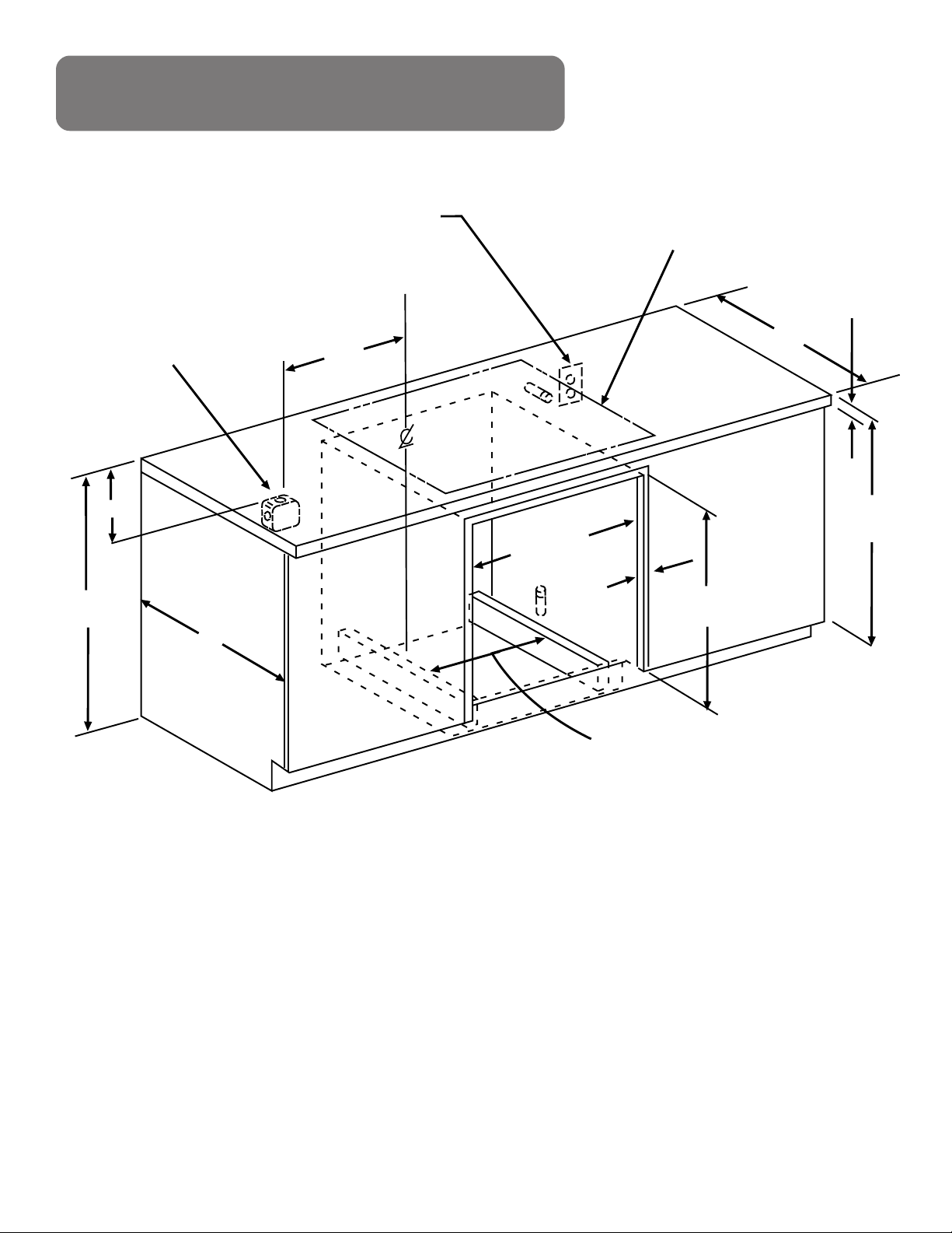
OPTION 1: IN CABINET INSTALLATION
2" x 4" or
Equivalent Runners
10"
Allow 7/8"
for overlap
of oven
over all
edges
of cutout.
Allow minimum of 20" for clearance
to adjacent corners, drawers, or walls, etc.
H
20"
20"
W
D
B
C
5"
A
Junction Box
Locations
34"
Min.
E
24"
20 1/2"
2" X 4" OR
EQUIVALENT
RUNNERS
27"
MIN.
6"
10 1/2"
MIN.
7"
10"
c c
19"
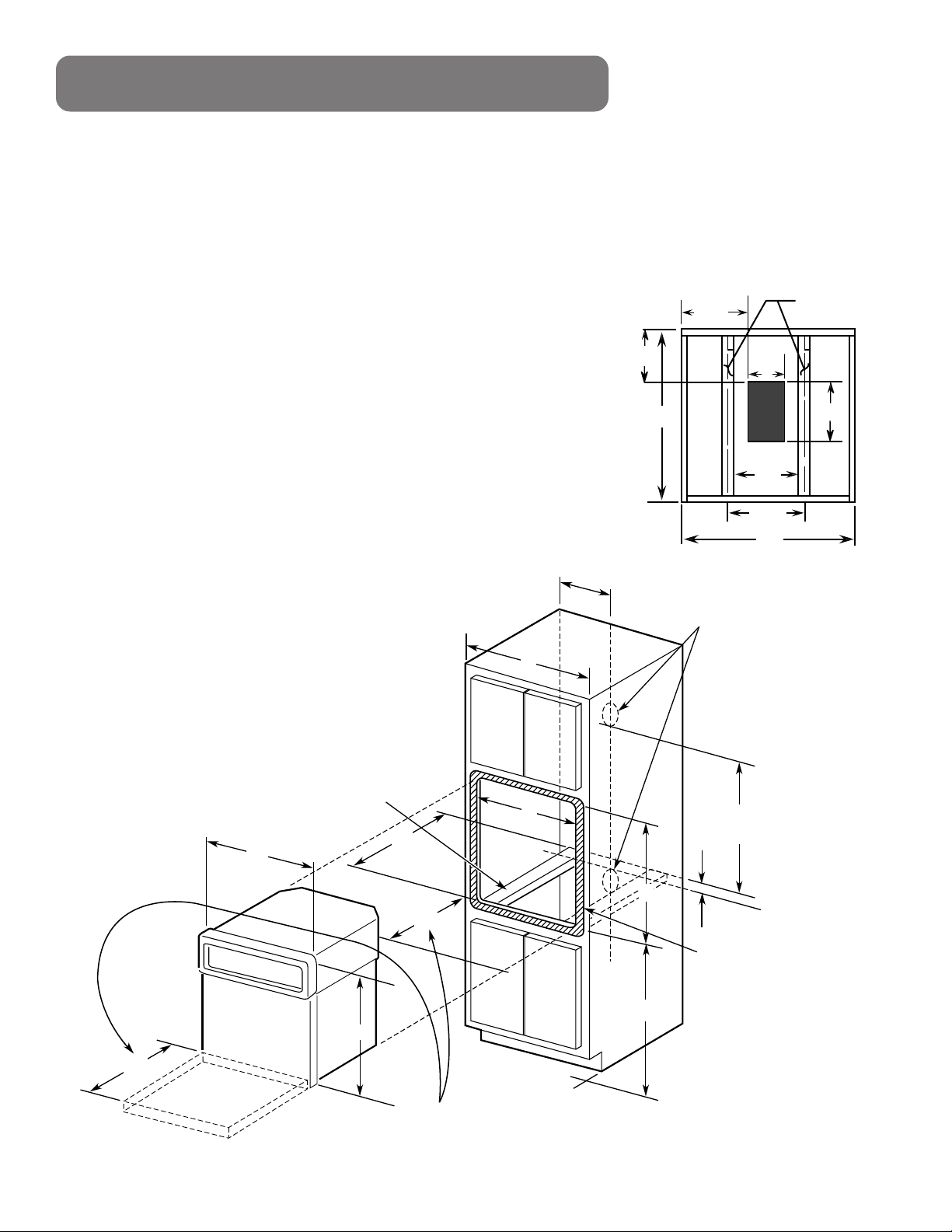
NOTE:
Locate an approved junction box in one of the suggested locations, a minimum of 34" above the
runners or 5" below the runners.
The oven can be installed in a 28 1/8" high cutout by proper use of long shims on bottom runners
and proper cabinet top retainer.
Be sure the oven support is solid enough to support 150 pounds. Also be sure the oven support is
level and straight. There is no way to level the oven after installation.
DIMENSIONS
A Cabinet Width 27"
B Cutout Width 25" Min./25 1/4" Max.
C Cutout Height 27 5/8" Min./28 1/8" Max.
D Cutout Depth 23 5/8" Min.
E Cutout Location 32 1/2"
H Overall Height 29 1/4"
W Overall Width 26 3/4"
Fig. 1 — SINGLE OVEN
3
Continued on next page
Page 4
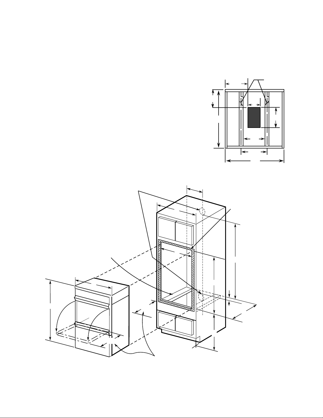
NOTE:
Junction Box
Locations
Allow 7/8" for
overlap of oven
over all edges
of cutout.
B
E
10"
56" MIN.
C
Allow minimum of 20"
for clearance to adjacent
corners, drawers, or walls etc.
5"
A
20"
D
2" x 4" or
Equivalent
Runners
W
H
20"
24"
20 1/2"
2" X 4" OR
EQUIVALENT
RUNNERS
27"
MIN.
6"
10 1/2"
MIN.
7"
10"
c c
19"
Locate an approved junction box in one of the suggested locations, a minimum of 56" above the
runners or 5" below the runners.
The oven can be installed in a 50 1/8" high cutout by proper use of long shims on bottom runners
and proper cabinet top retainer.
Be sure the oven support is solid enough to support 200 pounds. Also be sure the oven support is
level and straight. There is no way to level the oven after installation.
DIMENSIONS
A Cabinet Width 27" Min.
B Cutout Width 25" Min./25 1/4" Max.
C Cutout Height 49 11/16" Min./50 1/8" Max.
D Cutout Depth 23 5/8" Min.
E Cutout Location 13 1/4"
H Overall Height 51 1/4"
W Overall Width 26 3/4"
Fig. 2 — DOUBLE OVEN
4
Continued on next page
Page 5
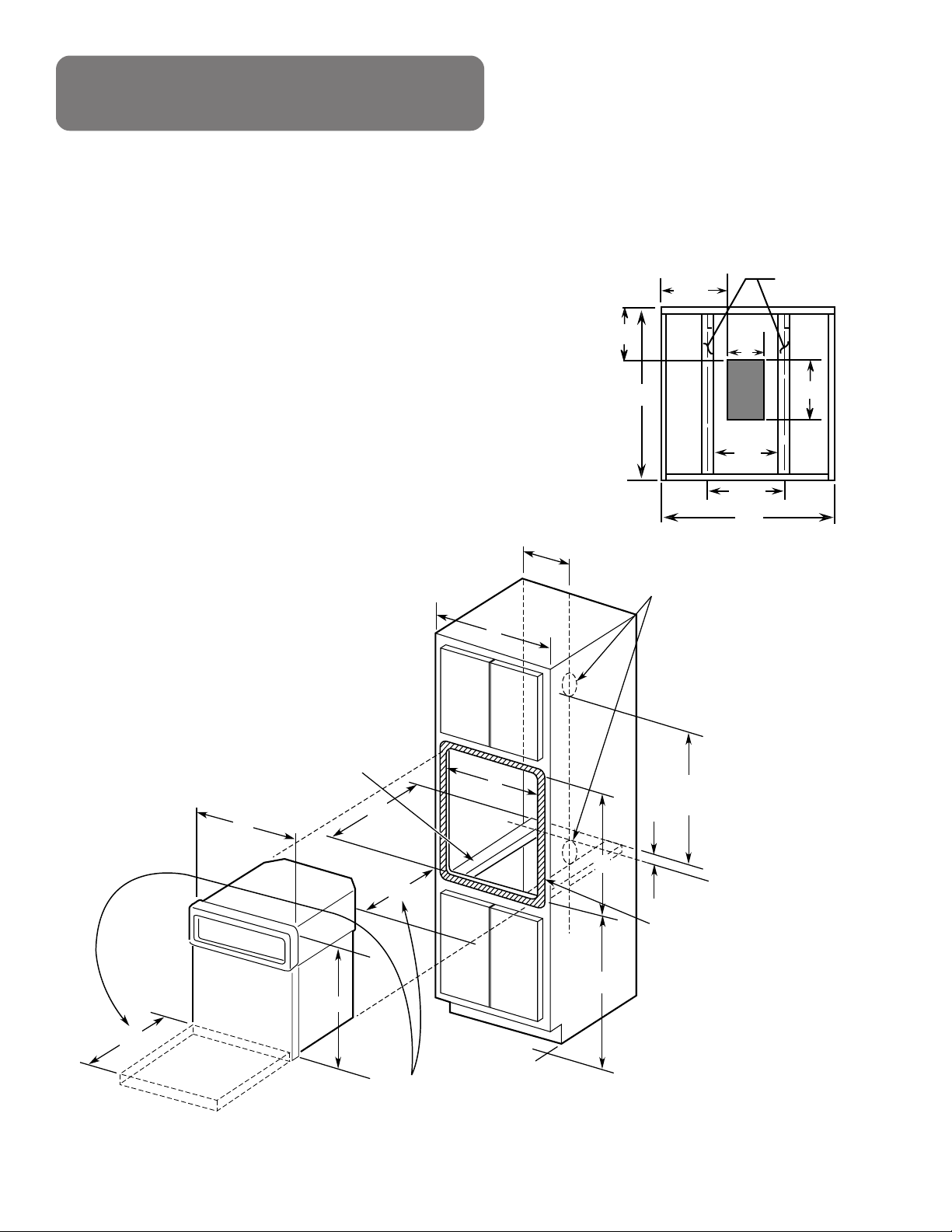
GAS AND ELECTRICAL CONNECTIONS FOR
GAS COOKTOP MUST BE LOCATED IN AN
ADJACENT ACCESSIBLE LOCATION TO THE
RIGHT.
JUNCTION BOX
LOCATION
14"
36"
24"
17 1/2"
GAS OR ELECTRIC COOKTOPS MAY BE INSTALLED OVER
THIS OVEN. SEE COOKTOP INSTALLATION INSTRUCTIONS
FOR CUTOUT SIZE. SEE LABEL ON TOP OF OVEN FOR
APPROVED COOKTOP MODELS.
25"
1 1/2" CABINET TOP
32"
MIN.
*
27 1/2" MIN.
28 1/8" MAX.
25" MIN.
25 1/4" MAX.
ALLOW
1" UNIT
OVERLAP
ALL EDGES
USE 2 — 2 X 4’s OR EQUIVALENT RUNNERS
SPACED 19" APART (ON INSIDE SURFACES)
CENTERED IN OPENING & FLUSH WITH TOP
OF TOE PLATE.
32" MIN. FROM TOP OF CABINET TO TOP OF RUNNERS MUST BE MAINTAINED.
*
5
Continued on next page
OPTION 2: UNDER COUNTER
INSTALLATION
MODELS APPROVED FOR UNDER THE COUNTER INSTALLATION:
47065, 47069
47169
47465, 47469
47466
48065, 48069
JKP15AW, JKP15BW, JKP15WW
JKP18AW, JKP18BW, JKP18WW
JKS05BW
5/8
Page 6

STOP POSITION
HINGE
Your built-in oven is packed with a shipping base pad on
6
SCREW
END
CAP
SIDE
TRIM
OVEN TO CABINET
MOUNTING SCREWS
*
Fig. 5
BROIL POSITION
Fig. 4A
HINGE
Fig. 4B
When the door is removed and hinge
arms are at broil position, do not
bump or try to move the hinge
arms. The hinges could snap back
causing an injury to the hands or damage to
the porcelain on the front of the range. Cover
the hinges with toweling or empty towel rolls
while working in the oven area.
HINGE
CAUTION:
REMOVE THE OVEN DOOR
• Slide oven 3/4 way into the cabinet cutout.
• Attach lower end caps and trim to front frame with 3
screws provided. (See Fig. 5).
NOTE: End caps snap into side trim.
• Slide oven all the way into the cabinet cutout.
• Drill pilot holes using a 3/32" drill bit.
If the cabinet is particle board you must use particle
board screws. They may be purchased at any hardware
store.
• Mount the oven with the screws supplied. (See Fig. 5)
INSTALLATION
REPLACE THE OVEN DOOR
• Hold the door over the hinges with the slots at the
bottom edge of the door lined up with the hinges. The
hinge arms must still be in the broil position.
• Slide the door down onto the hinges as far as it will go
and close the door. (See Fig. 6).
The bottom of the trim provides an
opening for cooling air to enter the
cabinet. This opening should never
be blocked.
STOP!
STOP!
the bottom of the unit. The lower front trim is shipped
separately and should not be used until you are ready to
install the oven with door removed. See Step 2.
• Open the door to the broil position. (See Fig. 4A).
• Grasp the door at each side and lift up and off the
hinges. (See Fig. 4B).
Fig. 6
Pub. No. 31-10200
SR10313
229C
4053P056-1
Recycled Paper
-Printed in The United States-
Page 7

INSTRUCCIONES DE INSTALACION PARA SU NUEVO
STOP!
HORNO INCORPORADO
Antes de empezar—Lea estas instrucciones completa y cuidadosamente.
IMPORTANTE—Guarde estas instrucciones para el uso del inspector local.
IMPORTANTE—OBSERVE TODOS LOS CODIGOS Y ORDENANZAS VIGENTES.
Nota al Instalador—Asegúrese de dejar las instrucciones con el Consumidor.
Consumidor—Guarde estas instrucciones para referencia futura.
Nota—Este artículo eléctrico debe hacer tierra debidamente (si es aplicable).
PARA SU SEGURIDAD
• Asegúrese de que su horno sea instalado
correctamente por un instalador calificado o
por un técnico de servicio.
• Asegúrese que el horno sea instalado a un
gabinete que esté firmemente pegado a la
estructura de la casa. El peso sobre la puerta
del horno podría causar que el horno se dé
vuelta y resultar en heridas. Nunca permita que
alguien se suba, se siente, se pare o se cuelgue
de la puerta del horno.
• Cerclórese de que los revestimientos de la
muralla, mesón y gabinetes pueden soportar el
calor generado por la estufa, horno y cubierta,
hasta 200°F.
HERRAMIENTAS QUE
NECESITARA
• Barreno de 3/32"
• Taladro eléctrico o de mano
• Destornillador de cabeza plana o Phillips
• Lápiz
• Cinta de medir o regla
• Sierra manual o eléctrica
UBICACION
Se debe proveer un espacio en el gabinete para encerrar
la parte trasera del horno incorporado. INSTALACION
PARA HORNO DE UNA UNIDAD – Vea la figura 1 para
todas las dimensiones necesarias. INSTALACION DE
HORNO DOBLE – Vea la figura 2 para todas las dimensiones
necesarias. Se recomienda hacer un padrón para obtener
un corte exacto.
Coloque el fondo del padrón sobre una línea base nivelada.
Vea la dimensión E en la figura 1 (Horno de una Unidad) en
la página 3, o en la figura 2 (Horno Doble) en la página 4.
Para una instalación bajo el mesón, vea la página 5. Vea
la figura 3 para las dimensiones del corte para instalar un
horno incorporado de una unidad de acuerdo a los modelos
de cubiertas para cocinar aprobadas.
REQUERIMIENTOS ELECTRICOS
¡ADVERTENCIA!
electricidad que corre hacia la
línea que alimenta al horno debe
desconectarse mientras se hacen
las conexiones. El no hacerio
podría causar serias heridas o
muerte.
Este artículo eléctrico debe ser alimentado con el voltage
y la frecuencia adecuada, y conectado correctamente a un
circuíto míltiple individual que hace tierra correctamente,
protegido por un interruptor de circuíto o fusible, y tener un
amperage como el que se requiere en la tabla de valores.
(La tabla de valores está ubicada en el marco del horno).
Recomendamos que tenga el alambrado y las conexiones
de su horno hechas por un electricista calificado. Después
de la instalación, haga que el electricista le muestre dónde
está ubicado el desconectador principal del horno.
Consulte con las compañías de utilidades locales referente
a los códigos eléctricos que se aplican en su área. El no
hacer el alambrado de acuerdo a los códigos vigentes,
podría resultar en condiciones peligrosas. Si no existen
códigos locales, su horno tiene que ser alambrado y tener
fusibles que cumplan con los requerimientos de los Códigos
Eléctricos Nacionales, ANSI/NFPA No. 70, última edición.
Puede obtener una copia escribiendo a:
National Fire Protection Association
Battery March Park
Quincy, MA 02269
Efectivo el 1 de enero, 1996, el Código Eléctrico Nacional
requiere que la construción del alambrado nuevo o
realambrado utilice una conexión de 4 conductores a un
aparato electrodoméstico. Cuando instale una estufa
eléctrica en una construcción nueva, siga las instrucciones
en CONEXION EN UNA CONSTRUCCION NUEVA Y EN
CIRCUITO CONDUCTOR DE CUATRO RAMAS.
Debe usar un sistema eléctrico de tres alambres, monofásico
de corriente alterna de 208y/120 Voltios o 240/120 Voltios,
60 Hertz. Si conecta a un alambrado de aluminio, deben
usarse conectores propiamente instalados y aprobados
para uso con cables de aluminio.
La
Pub. No. 31-10200
SR10313
229C
4053P056-1
1
Continued on next page
Page 8

CONEXION ELECTRICA
STOP!
STOP!
1. Desconecte la electricidad que va al circuito multiple
del horno.
2. Con el horno frente a la abertura del gabinete, conecte
el conducto flexible a la caja de empalme de manera
que cuelgue en forma natural sobre el lado izquierdo de
la pared trasera cuando se instala el horno. No acorte
este conductor flexible de electricidad. El tubo flexible
del conductor debe conectarse bien a la caja de
empalme y si el conducto flexible no encaja dentro del
conector, no instale el horno hasta que se obtenga un
conductor de tamaño apropiado.
• "Todas las construcciones nuevas, casas móviles e
instalaciones donde los códigos locales no permiten
hacer tierra a través de neutral, requieren un circuito
conductor de cuatro ramas. Para construcciones
existentes, se puede usar un circuito conductor de tres
ramas".
NOTA AL ELECTRICISTA:
eléctricos que se proveen con este horno son
reconocidos por UL para conexiones a alambres de
mayor tamaño en la residencia. El aislante de estos 3
alambres ha sido evaluado a temperaturas mucho más
altas que el valor de los alambres de la residencia. La
capacidad de conducción de corriente del conductor
está gobernado por el valor de la temperatura del
aislante alrededor del alambre, en vez del tamaño del
alambre por si solo.
Los tres alambres
INSTRUCCIONES ESPECIALES
PARA HACER TIERRA
• Cuando conecte a un circuíto múltiple de 4 conductores,
o
• Cuando instale el horno en una casa de tipo Móvil, o
• Cuando los códigos locales no permitan hacer tierra a
través de neutral:
1. Corte el alambre conector neutral (blanco) del forro.
Recorte el alambre conector neutral (blanco) para
exponer el largo apropiado del conductor.
2. Conecte el alambre para hacer tierra (verde o cobre
pelado) al conductor para hacer tierra (verde o cobre
pelado) de la residencia de acuerdo a los códigos
locales. Si el conductor para hacer tierra de la residencia
es de aluminio, vea la nota
3. Conecte el alambre neutral del horno (blanco) al alambre
neutral de circuíto múltiple (blanco o gris) de acuerdo
a los códigos locales.
4. Conecte el alambre rojo del horno al alambre rojo del
circuíto múltiple y el alambre negro del horno al alambre
negro del circuíto múltiple de acuerdo a los códigos
locales. Si el alambre rojo, negro o blanco de la
residencia son conductores de aluminio, vea la nota de
"¡ADVERTENCIA!"
"¡ADVERTENCIA!"
CONEXION DE CIRCUITO
CONDUCTOR DE TRES RAMAS
• Cuando conecte al circuíto múltiple de 3 alambres, si
los códigos locales lo permiten, conecte el conductor
pelado que va a tierra del horno con el alambre de
contacto forrado neutral (blanco) al alambre de contacto
del circuíto múltiple neutral (de color blanco o gris), el
alambre de contacto rojo del horno al alambre de
contacto rojo del circuíto múltiple y el alambre de
contacto negro del horno al alambre negro del circuíto
múltiple en cumplimiento de los códigos locales.
¡ADVERTENCIA!:
La conexión inadecuada de los
alambres de aluminio de la casa
a los conductores de cobre podría
resultar en un peligro eléctrico o
en un incendio. Use solamente
conectores diseñados para unir cobre con
aluminio y siga de cerca los procedimientos
recomendados por el fabricante.
PARA TODAS LAS INSTALACIONES
El horno puede ser sostenido por una base sólida o por dos
soportes. La base sólida o los dos soportes deben estar
nivelados con la orilla del fondo del corte.
El peso completo del horno es sostenido por los soportes
de 2" x 4" o el equivalente. Esté seguro que estos soportes
estén nivelados, montados rígidamente y a un espacio de
20 1/2" sobre el centro. El espacio entre los soportes es de
19" de ancho.
NOTA:
Si se usa una base sólida en vez de
soportes, un rectángulo de 6" x 10" debe
ser cortado en el fondo (Vea Fig. 1) para
un funcionamiento óptimo y una
circulación de aire adecuada.
IMPORTANTE:
Saque todos los materiales
de empaque y la literatura de
la cubierta para cocinar antes de conectar el gas y la
electricidad a la estufa.
2
Continued on next page
Page 9
OPCION 1: INSTALACION
Soportes de
2" x 4"
o equivalente
10"
Permita una salida del horno
de 7/8" por todas las orillas
del corte
Permita un espacio de 20" a
esquinas adyacentes, cajones,
o murallas, etc.
H
20"
20"
W
D
B
C
5"
A
Ubicación de
caja de conexión
34"
Min.
E
24"
20 1/2"
Soportes de
2" x 4" o
equivalente
27"
MIN.
6"
10 1/2"
MIN.
7"
10"
c c
19"
EN EL GABINETE
NOTA:
Coloque una caja de conexión aprobada en uno de los lugares sugeridos; a un mínimo de 48" sobre los soportes
o 5" bajo los soportes.
Esté seguro que los soportes del horno sean suficientemente sólidos para soportar 150 libras. También, esté
seguro que el soporte del horno esté nivelado y derecho. No hay forma de nivelar el horno después de que esté
instalado.
DIMENSIONES
A Ancho del gabinete 27"
B Ancho del corte 25" Min./25 1/4" Max.
C Altura del corte 27 5/8" Min./28 1/8" Max.
D Profundidad del corte 23 5/8" Min.
E Ubicación del corte 32 1/2"
H Altura total 29 1/4"
W Ancho total 26 3/4"
Fig. 1 – SINGLE OVEN
3
Page 10

NOTA:
Ubicación de
caja de conexión
Permita una salida del horno
de 7/8" por todas las orillas
del corte
B
E
10"
56" MIN.
C
Permita un espacio de 20" a
esquinas adyacentes, cajones,
o murallas, etc.
5"
A
20"
D
Soportes de
2" x 4"
o equvalente
W
H
20"
24"
20 1/2"
Soportes de
2" x 4" o
equivalente
27"
MIN.
6"
10 1/2"
MIN.
7"
10"
c c
19"
Coloque una caja de conexión aprobada en uno de los lugares sugeridos; a un mínimo de 48" sobre los soportes
o 5" bajo los soportes.
Esté seguro que los soportes del horno sean suficientemente sólidos para soportar 150 libras. También, esté
seguro que el soporte del horno esté nivelado y derecho. No hay forma de nivelar el horno después de que esté
instalado.
DIMENSIONES
A Ancho del gabinete 27"
B Ancho del corte 25" Min./25 1/4" Max.
C Altura del corte 27 5/8" Min./28 1/8" Max.
D Profundidad del corte 23 5/8" Min.
E Ubicación del corte 32 1/2"
H Altura total 29 1/4"
W Ancho total 26 3/4"
Fig. 2 – DOUBLE OVEN
4
Page 11

GAS AND ELECTRICAL CONNECTIONS FOR
GAS COOKTOP MUST BE LOCATED IN AN
ADJACENT ACCESSIBLE LOCATION TO THE
RIGHT.
JUNCTION BOX
LOCATION
14"
36"
24"
17 1/2"
GAS OR ELECTRIC COOKTOPS MAY BE INSTALLED OVER
THIS OVEN. SEE COOKTOP INSTALLATION INSTRUCTIONS
FOR CUTOUT SIZE. SEE LABEL ON TOP OF OVEN FOR
APPROVED COOKTOP MODELS.
25"
1 1/2" CABINET TOP
32"
MIN.
*
27 1/2" MIN.
28 1/8" MAX.
25" MIN.
25 1/4" MAX.
ALLOW
1" UNIT
OVERLAP
ALL EDGES
USE 2 — 2 X 4’s OR EQUIVALENT RUNNERS
SPACED 19" APART (ON INSIDE SURFACES)
CENTERED IN OPENING & FLUSH WITH TOP
OF TOE PLATE.
32" MIN. FROM TOP OF CABINET TO TOP OF RUNNERS MUST BE MAINTAINED.
*
LAS CONEXIONES DE GAS Y
ELECTRICIDAD PARA UNA CUBIERTA
DEBE INSTALARSE EN UNA POSICION
ACCESIBLE A LA DERECHA.
* SE DEBE MANTENER 32" MIN. DE LA SUPERFICIE DEL GABINETE A LOS SOPORTES
USE 2 SOPORTES DE 2X4 O EL
EQUIVALENTE A 19" DE DISTANCIA (EN
LAS SUPERFICIES INTERIORES)
CENTRADAS CON LA ABERTURA Y
PEGADA A LA PLANCHA DELANTERA.
SUPERFICIE DEL
GABINETE
UBICACION DE LA
CAJA DE EMPALME
CUBIERTAS DE ESTUFAS A GAS O ELECTRICAS
PUEDEN SER INSTALADAS SOBRE ESTE HORNO.
VEA LAS INSTRUCCIONES PARA INSTALACION
PARA EL TAMAÑO DEL CORTE. VEA LA ETIQUETA
SOBRE EL HORNO PARA LOS MODELOS DE
CUBIERTA APROBADOS.
5/8"
OPCCION 2: INSTALACION BAJO LA
SUPERFICIE DEL MESON
PERMITA UN
SOBRETECHO
DE 1" EN
TODAS LAS
ORILLAS
MODELOS APROBADOS PARA LA INSTALACION BAJO EL GABINETE
47065, 47069
47169
47465, 47469
47466
48065, 48069
JKP15AW, JKP15BW,
JKP15WW
JKP18AW, JKP18BW,
JKP18WW
JKS05BW
5
Page 12

Su horno tipo “Built-In” está empacado con una base
STOP!
STOP!
Posición de tope
para asar a la parrilla
Bisagra
* DEL HORNO A LOS
TORNILOS DE MON-
TAGE DEL GABINETE
TAPA DE
PUNTA
TORNILLO
MOLDURA
DEL LADO
acolchonada en el fondo de la unidad. La moldura del
frente de abajo y las cubiertas de las puntas vienen
separadas y no se deben usar hasta que usted esté listo
para instalar el horno con la puerta sacada después de
haber hecho las conexiones eléctricas. Vea el Paso 2.
SAQUE LA PUERTA
DEL HORNO
• Abra la puerta a la posición de paro (Vea Fig. 4A).
• Tome la puerta de cada lado y levántela de las bisagras
(Vea Fig. 4B).
Fig. 4A
Fig. 4B
PRECAUCION:
Cuando la puerta se saca y los
brazzs de las bisagras están en la
posición de paro, no pase a
llevarlos o trate de mover los
brazos de las bisagras. Las
bisagras se podrían cerrar de golpe y causarle
heridas en las manos o dañar la porcelana en
el frente del aparato. Cubra las bisagras con
toallas o rollos vacíos de toallas cuando
trabaje en el área del horno.
El fondo de la moldura provee una
abertura para que el aire frío entre
al gabinete. Esta abertura nunca
debe ser obstruida.
Fig. 5
PARA REINSTALAR
LA PUERTA DEL HORNO
• Sujete la puerta sobre las bisagras con las ranuras de
la orilla del fondo alineadas con las bisagras. Los
brazos de las bisagras deben estar todavía en la
posición de paro.
• Deslice la puerta hacia abajo en las bisagras lo más
posible y cierre la puerta. (Vea Fig. 6).
INSTALACION
• Deslice el horno 3/4 de distancia dentro del corte del
gabinete.
• Instale las tapas de las puntas y la moldura de abajo en
el frente del marco con los tornillos que se proveen.
(Vea Fig. 5).
NOTA: Las tapas de las puntas se encajan a presión en la
moldura de los lados.
• Meta el horno completamente en el corte del gabinete.
• Haga hoyos pilotos de 3/32" para tres tornillos #8 a
través de los hoyos de montaje en la cubierta de arriba.
• Los Tres tornillos deben estar a 1/4" mín. de la parte de
arriba del corte (Vea Fig. 5).
Pub. No. 31-10200
SR10313
229C
4053P056-1
6
Fig. 6
BISAGRA
Reciclado Papel
– Impreso en los Estados Unidos –
 Loading...