

Page 1

Professional side burner
BGC models
Installation instructions
and User guide
Brûleur professionnel de côté
Modèles BGC
Instructions d’installation
et Guide d’utilisation
US CA
Page 2

Page 3
A MESSAGE TO OUR CUSTOMERS
We are glad that you selected the professional side burner by DCS. Because this appliance contains features not
found on any other burner, we recommend that you read this entire booklet before your first use. Keep it in a
handy place as it has answers to questions that may occur during future use.
Feel free to contact us if we can help you. When you write please include the model and serial number of the
Burner. We thank you for buying the professional side burner and wish you many years of enjoyment.
To help serve you better, please fill out and submit your Product Registration by visiting our website at www.
dcsappliances.com and selecting “Customer Care” on the home page and then select “Product Registration”.
For your convenience, product questions can be answered by a DCS Customer Care Representative by phone:
1-888-936-7872, or email: customer.care@fisherpaykel.com.
NOTE: Please write the Model, Code and Serial Numbers on this page for references (located on the inside of the
left side of the appliance)
MODEL NUMBER CODE SERIAL NUMBER
NOTE: Inspect the product to verify that there is no shipping damage. If any damage is detected, call the shipper
and initiate a damage claim. DCS by Fisher & Paykel is not responsible for shipping damage.
DO NOT discard any packing material (box, pallet, straps) until the unit has been inspected.
WARNING!
Improper installation, adjustment, alteration, service or maintenance can cause property damage, injury or death.
Read the installation, operating and maintenance instructions thoroughly before installing, using or servicing this
equipment.
WARNING!
If the information in this manual is not followed exactly, a fire or explosion may result causing property damage,
personal injury or death. Do not store or use gasoline or other flammable vapors and liquids in the vicinity of this or
any other appliance. An LP cylinder not connected for use shall not be stored in the vicinity of this or any other appli
ance.
WARNING!
Do not try lighting this appliance without reading the “Lighting Instructions” section of this manual. This outdoor
cooking gas appliance is not intended to be installed in or on recreational vehicles , boats or in a non-ventilated
room. For outdoor use only.
FOR YOUR SAFETY
If You Smell Gas:
1. Shut off gas to the appliance.
2. Extinguish any open flames.
3. Open lid.
4. If odor continues, immediately call your gas supplier or your fire department
Installation and service must be performed by a qualified installer, service agency or the gas supplier.
-
PLEASE RETAIN THIS MANUAL FOR FUTURE REFERENCE.
1
Page 4

2
Page 5

TABLE OF CONTENTS
SAFETY PRACTICES AND PRECAUTIONS 45
INSTALLATION
Installation of Side Burner on 30” Cart 6-9
Installation of Side Burner Built-in Model 10-11
Gas Hook-up 12-13
Leak Testing 14
Burner Adjustment 14
Installer Checklist 15
USING THE SIDE BURNER
Lighting Instructions 16
CARE AND MAINTENANCE 17
TROUBLESHOOTING 18
SERVICE 19
3
Page 6

SAFETY PRACTICES & PRECAUTIONS
Improper use or installation is dangerous. Carefully follow these instructions.
n
Always remove the cover before lighting the professional side burner. Never use the side burner if a leak is
present.
n
Do not use a flame to check for gas leaks.
n
Do not let children use the side burner.
n
Do not leave children unattended near the side burner.
n
Never let children crawl or hang on the side burner.
n
Exercise care when operating the side burner. The burner grate can get hot enough to cause burns during
operation .
n
Never leave the side burner on unattended.
n
Always wait 5 minutes before relighting the burner to allow any accumulated gas to dissipate. Should the burner
go out during use, turn off the gas valve and wait 5 minutes before attempting to relight. Always follow the light
ing instructions. Never lean over a lit burner.
n
Never cook without the drip pan in place, pushed all the way to the rear of the burner box.
n
Use only in well ventilated areas.
n
Do not use in garages, breezeways, sheds, or other such enclosed areas.
n
Keep the area surrounding the side burner clear and free from combustible materials, gasoline, other flammable
liquids or vapors, charcoal lighter fluid, and trash.
n
Do not obstruct the flow of combustion and ventilation air to the side burner. On cart mounted units, keep area
beneath the burner free of debris. If the burner is built-in, do not store gas cylinders beneath the unit without
adequate ventilation.
WARNING!
Do not store items of interest to children above or at the back of any appliance. Children could be seriously injured if
they should climb onto the appliance to reach these items.
n
Keep the side burner covered when not in use.
n
Never connect an unregulated gas line to the side burner.
n
If the side burner has not been used for an extended period of time (over winter, for example) the unit should be
checked for gas leaks and obstructions in the burner.
n
Thoroughly clean the side burner on a regular basis.
n
Only use the side burner with the type of gas specified on the rating plate. To change from LP gas to natural, or
vice versa, a factory conversion kit (see page 10 for conversion kit information) is required.
NOTE:
This product must be installed by a licensed plumber or gas fitter when installed within the Commonwealth of
Massachusetts.
4
Page 7
SAFETY PRACTICES & PRECAUTIONS
SPIDER AND INSECT WARNING!
Spiders and insects can nest in the burner(s) or orifices of this or any other gas appliance, and can block or restrict
the burner. This can cause a flash back to the control panel. This is a very dangerous condition which can cause a fire
to occur, thereby damaging the unit and making it unsafe to operate.
You must inspect the burner(s) at least once a year or immediately if any of the following conditions occur:
1. The smell of gas in conjunction with the burner flames appearing yellow.
2. The side burner(s) does not reach temperature.
3. The side burner(s) heats unevenly.
4. The burner(s) make popping noises.
n
Do not attempt to disconnect any gas connections while your burner is in use, or the gas supply is on.
n
When the side burner is stored indoors the gas supply must be disconnected and, if using an LP gas cylinder, the
cylinder must be stored outdoors in a well-ventilated area.
n
Keep any electrical supply cord away from the heated surfaces of the professional side burner.
n
On cart mounted units, never move without first allowing the side burner and/or grill to cool and ensuring that
the gas supply is turned off. Fold the side shelf down, and push; never pull the grill.
n
Never use the side burner in a windy area.
INSTALLATION
INSTALLATION OF SIDE BURNER ONTO 30” CART BGC 131/132 MODELS ONLY
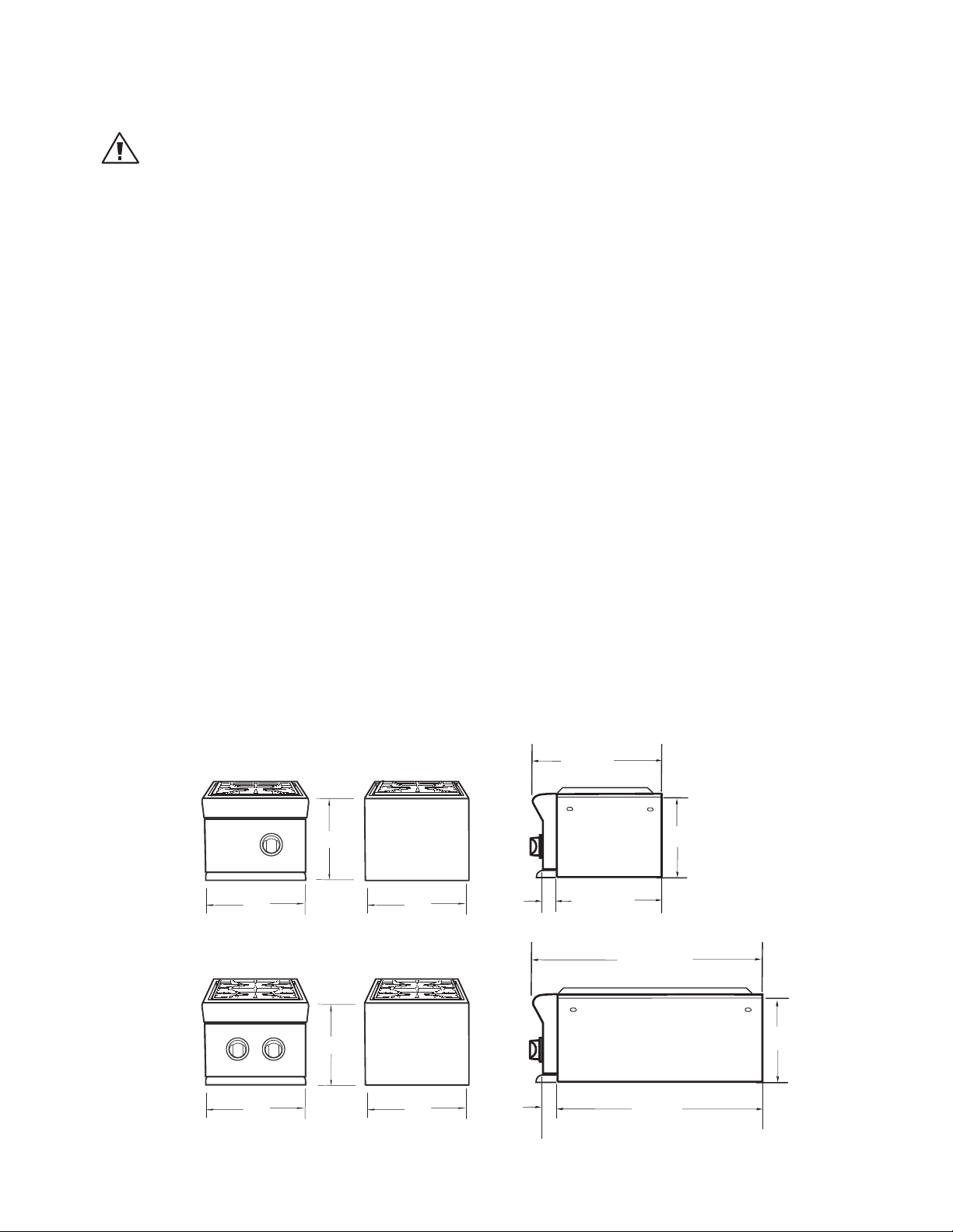
SIDE BURNER DIMENSIONS
Single Side Burner
BURNER
IGNITION
FRONT
13
"
10 - 5/8 "
Double Side Burner
13
REAR
"
"
2
15
-3/4"
12-
SIDE
3/4 "
26-
10 -1/8"
3/4"
IGNITION
REAR
"
13
FRONT
FRONT
10 - 5/8 "
13
REAR
"
"
2
23-
SIDE
3/4"
10 -1/8"
5
Page 8
INSTALLATION
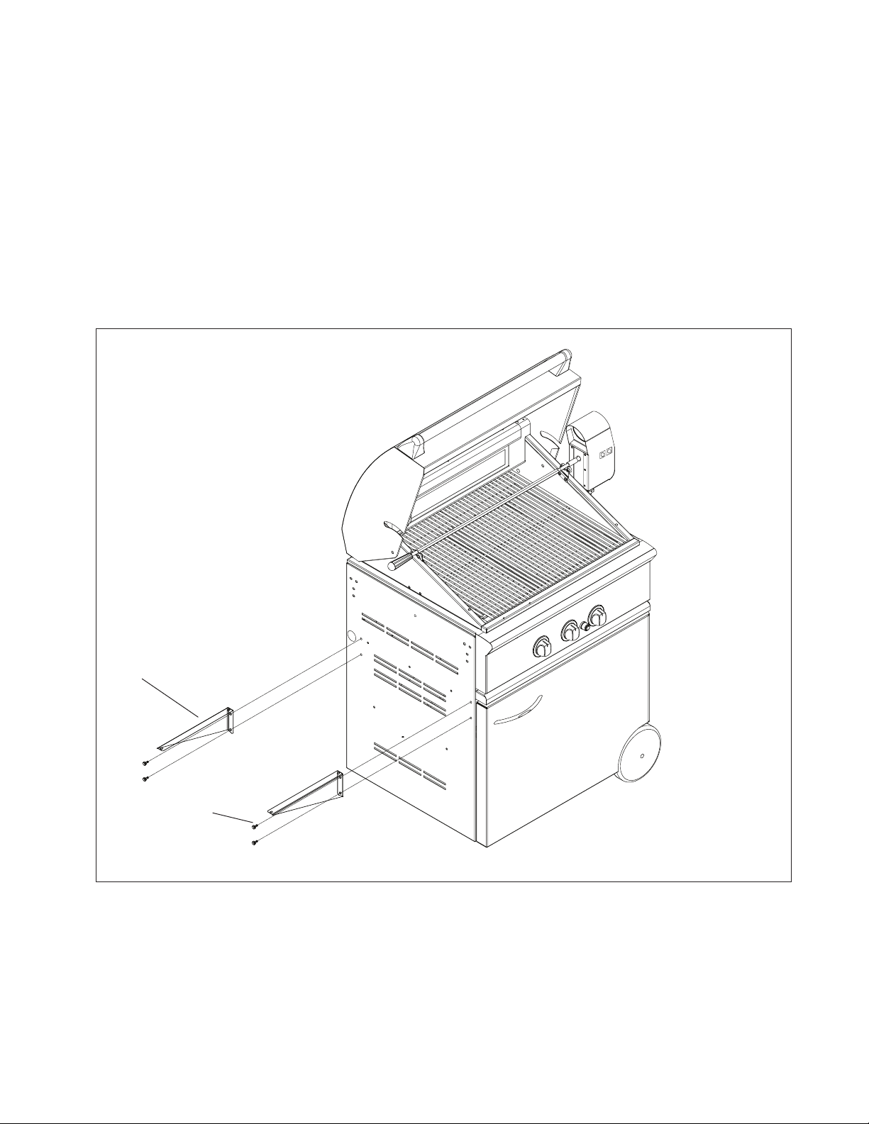
INSTALLATION OF SIDE BURNER ON BGB30CSS CART
STEP 1
Remove the cover, grate, and drip pan from the side burner.
STEP 2
Bolt the support brackets to the grill cart side panel with (4) 1/4 x 20 bolts provided.
Note:
For the BGC131 side burner only, use (2) #10 sheet metal screws to bolt the back support bracket.
SUPPORT BRACKET
6
BOLT
FIG. 01
Page 9
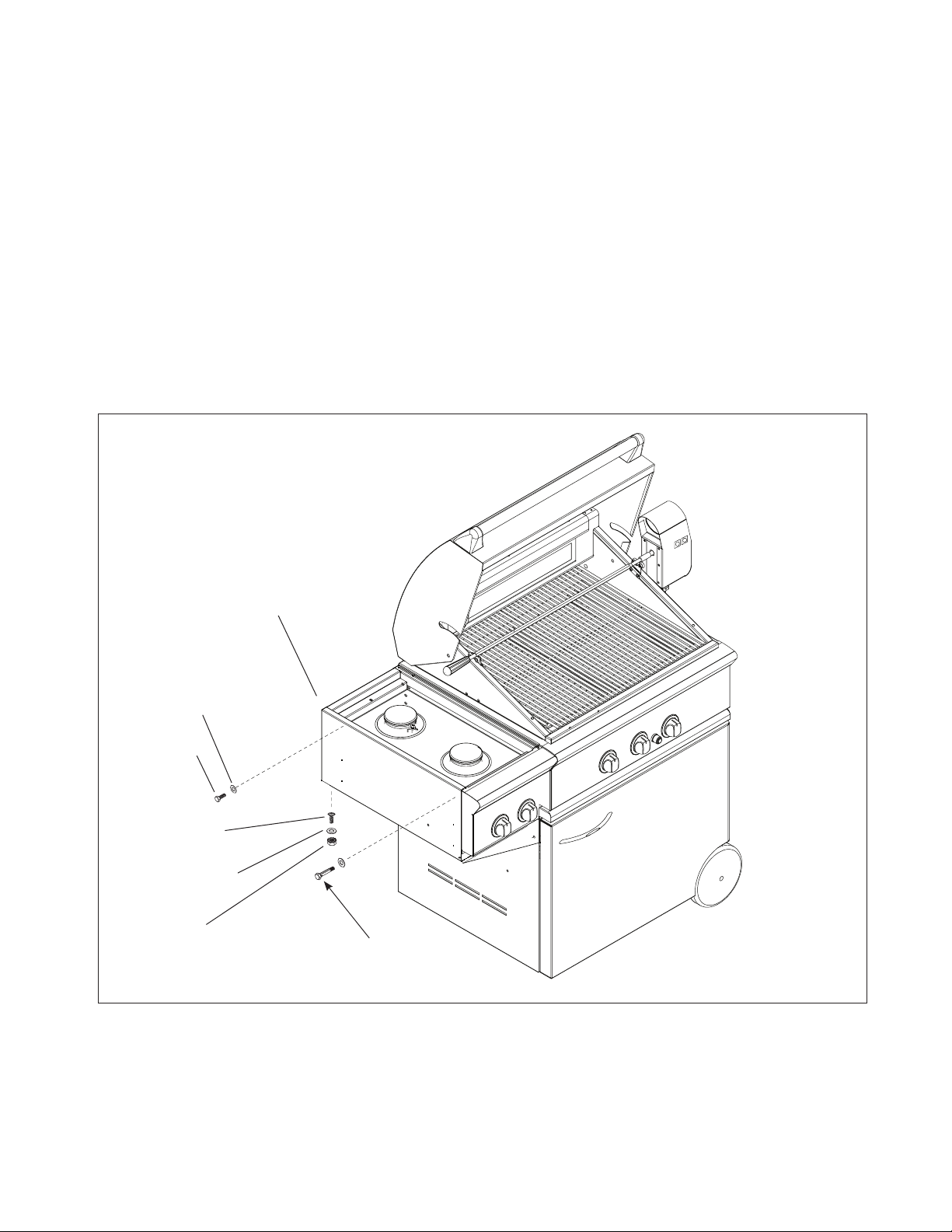
INSTALLATION
INSTALLATION OF SIDE BURNER ON BGB30CSS CART
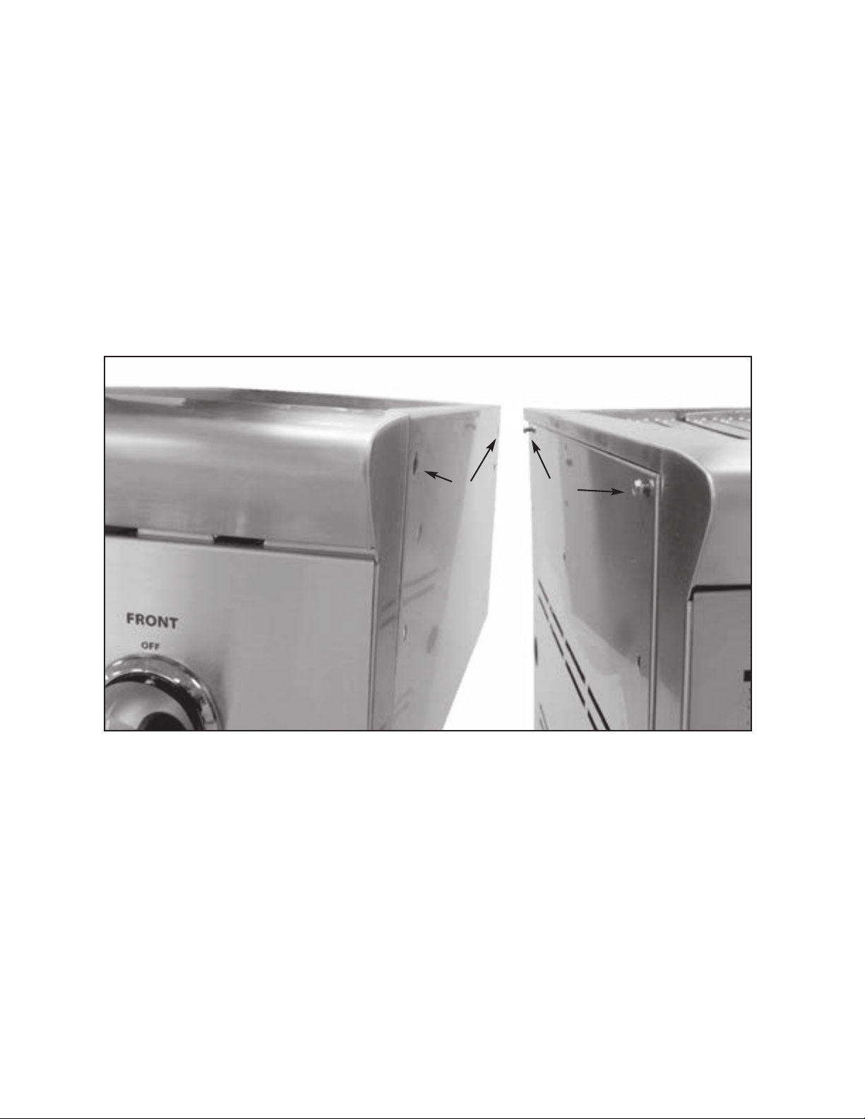
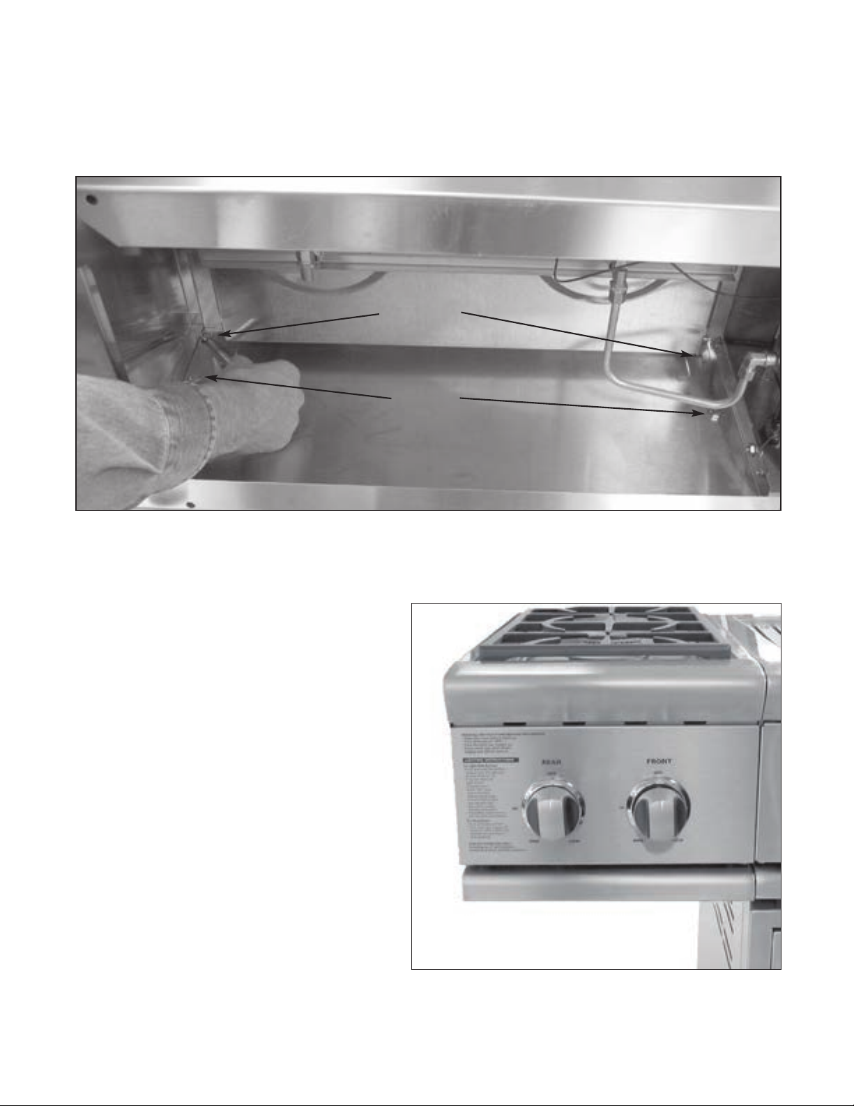
STEP 3
1. Bolt the side burner to the grill cart side panel from the under side of the burner assembly with a shoulder bolt
in the front and 1/4 x 20 bolt in the back as shown. Do not forget to use 1/4 flat washers. Do not tighten. Adjust
the side burner until it is level to the grill; then tighten securely.
2. Bolt the support brackets to the bottom of the side burner with (4) #10-24 machine screws, nuts and washers
provided.
3. Replace the drip pan, grate and cover.
Note:
Once the side burner is assembled, refer to the “Gas Requirements” section for proper gas hook-up requirements.
WASHER FLAT
1/4 X .938 (2PCS)
BOLT (1/4 – 20)
SCREW #10 (4 PCS)
WASHER #10 (4 PCS)
NUT#10 (4 PCS)
SIDE BURNER
Shoulder Bolt
1/4-20 x 5/16
FIG. 02
7
Page 10
INSTALLATION
ADDENDUM – SIDE BURNER INSTALLATION
MODELS: BGB131/BGB132
Contents Qty. Part No.
2 211338
2 211328
Hex head bolt
10-24 x 1
Hex head bolt
1/4-20 x 3/4
Tools Required
5/16 Wrench
7/16 Wrench
INSTALLATION OF SIDE BURNER ON CAD130 CART
STEP 1
Remove the cover, grate, and drip pan from the side burner.
STEP 2
Attach the two provided 10-24 x 1 hex head bolts to the upper holes of the side panel. Do not completely tighten
them yet. Leave an 1/8” space under the bolt head as shown on Fig. 03.
STEP 3
Use these two bolts to attach the side burner through the keyholes as shown on Fig. 03.
Keyholes
Bolts
(211338)
FIG. 03
8
Page 11
INSTALLATION
Apply vertical pressure to the side burner to align it with the grill cart. Attach the two provided
1/4-20 x 3/4 hex head bolts (211328) to the lower holes as shown in Fig. 02. Tighten the four bolts.
INSTALLATION OF SIDE BURNER ON CAD130 CART
Apply vertical pressure to the side burner to align it with the grill cart. Attach the two provided 1/4-20 x 3/4 hex
head bolts to the lower holes as shown in Fig. 04. Tighten the four bolts.
Bolts
(211338)
Bolts
(211328)
FIG. 04
NOTE:
Once the side burner is assembled, refer to the “Gas Requirements” section for proper gas hook-up requirements.
Assembled Side Burner to CAD1-30 Cart
9
Page 12
INSTALLATION
INSTALLATION OF SIDE BURNER, BUILTIN MODEL
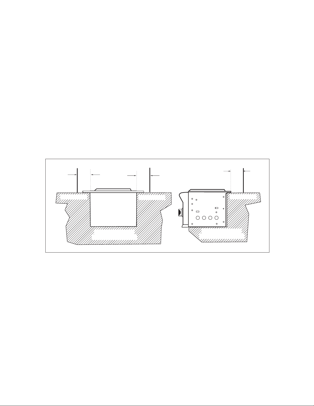
All BGC131-BI and BGC132-BI models can be installed into a combustible enclosure with zero clearance from
the back, side and bottom below the counter top level as shown in Fig. 05.
A minimum of 6” from the back and sides must be maintained from the professional side burner above the
cooking surface (see Fig. 05).
When determining a suitable location, take into account concerns such as exposure to wind, proximity to traffic paths, and keeping any gas supply lines as short as possible. Locate the side burner only in a well-ventilated area. Never locate the side burner in a garage, breezeway, shed, or other such enclosed areas.
It is recommended that ventilation holes are provided in the enclosure in the event of a gas leak. The counter
and supporting ledges or deck must be level and flat.
Important!
Gas fittings, regulator, and installer-supplied shut-off valves must be easily accessible.
6"
min.
COUNTER TOP
BACK VIEW
COMBUSTIBLE OR
NON-COMBUSTIBLE
6"
min.
COUNTER TOP
FIG.05
6"
min.
COUNTER TOP
COMBUSTIBLE OR
NON-COMBUSTIBLE
10
Page 13
INSTALLATION
22-
1/8"
25-
1/2"
10-1/8"
25-
1/2"
11-
3/4"
2
"
14
-3/4"
Single Side Burner
Dual Side Burner
10-1/8"
14
-9/16"
REAR
FRONT
IGNITION
BURNER
IGNITION
10 - 5/8 "
13
"
13
"
13
"
13
"
10 - 5/8 "
12-
3/4 "
15
-3/4"
10 -1/8"
23-
3/4"
10 -1/8"
26-
3/4"
Single Side Burner
Double Side Burner
2
"
2
"
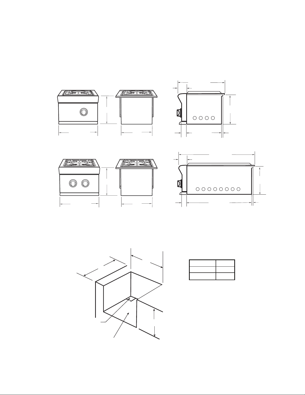
INSTALLATION OF SIDE BURNER, BUILTIN MODEL
SIDE BURNER DIMENSIONS
Single Side Burner
IGNITION
BURNER
14-9/16
FRONT
"
10 - 5/8 "
Double Side Burner
IGNITION
REAR
FRONT
10 - 5/8 "
"
14-9/16
FRONT
"
12
REAR
12
REAR
"
"
2
"
2
16
11-
-1/16"
3
-1/8"
SIDE
3
-1/8"
3/8"
26-
22-
10-1/8"
5/8"
1/8"
SIDE
1/2"
10-1/8"
1/2"
STANDARD CONSTRUCTION CUTOUT REQUIREMENTS
A
2" X 2" opening
for gas supply line
note: the deck is
not required
12"
10-
1/8"
MODEL A
BGC131-BI 12"
BGC132-BI 22-3/4"
11
Page 14
INSTALLATION
GAS HOOKUP
GAS REQUIREMENTS:
Verify the type of gas supply to be used, either natural or LP. Make sure the marked gas on the appliance rating plate(s) and hook-up kit agrees with that of the supply.
IMPORTANT!
Never connect an unregulated gas line to the appliance.
An installer supplied gas shut-off valve must be installed in an easily accessible location.
All pipe sealants must be an approved type and resistant to the actions of LP gases. Never use pipe sealant on
flare fittings.
Gas conversion kits are available from the factory. When ordering, have the model number, and the type of gas
(natural or LP) which you need.
Total gas consumption of the professional side burner with burner(s) on “HIGH” – Table 1 below.
TABLE 1
MODEL Btu/hr
BGC131 17,000
BGC132 34,000
BGC131-BI 17,000
BGC132-BI 34,000
The appliance and its individual shut-off valve must be disconnected from the gas supply piping system during
any pressure testing of that system at test pressures in excess of 1/2 PSIG (3.5kPa.).
The appliance must be isolated from the gas supply piping system by closing its individual manual shut-off
valve during any pressure testing of the gas supply piping system at test pressures equal to or less than 1/2
PSIG (3.5 kPa.).
The installation of this appliance must conform with local codes or in the absence of local codes, with the National Fuel Gas Code, ANSI Z223.1/NFPA 54. Installation in Canada must be in accordance with the Standard
CSA B149 and/or .2 (installation code for gas burning appliances and equipment) and local codes.
All gas connections must be made by a qualified technician.
NATURAL GAS HOOKUP:
CONNECTION: 1/2” NPT male with 3/8” flare adapter.
OPERATING PRESSURE: 4.0” W.C.
SUPPLY PRESSURE: 5” to 14” W.C. If in excess of 14” W.C., a step down regulator is required.
Check with your local gas utility company or with local codes for instructions on installing gas supply lines. Be
sure to check on type and size of run, and how deep to bury the line. If the gas line is too small, the professional side burner will not function properly.
12
Page 15

INSTALLATION
GAS HOOKUP
NATURAL GAS HOOKUP (continued)
To hook-up the fittings supplied with the side burner, assemble as shown in Fig.06. Use joint compound on
male threads only.
Do not use joint compound on the flare end of the 1/2” NPT to 3/8”
flare adapter. Ensure that the regulator arrow points in the direction of
gas flow-towards the unit, away from the supply.
Bottom of
131 &132 Burner
Do not forget to place the installer-supplied gas valve in an accessible
location.
LP GAS HOOKUP
CONNECTION: 1/2” NPT female with 3/8” flare adapter
(included). Use 90º elbow 1/2” NPT with 3/8” flare
(P/N 212394) for side mount models only when installing on the cart.
Use sealer on 1/2” NPT threads only.
OPERATING PRESSURE: 11.0” W.C. side burner uses the LP regulator
from adjoining grill.
Open Top
Manifold
To Gas Supply
1/2" Coupling
1/2" NPT x 2.0”
Nipple
Regulator
1/2" NPT x 2.0”
Nipple
1/2" NPT to 3/8"
Flare Adapter
SUPPLY PRESSURE: 12” to 14” W.C.
Apply joint compound to the threaded end of the side burner gas
FIG. 06 Natural Gas
inlet and tighten the adapter to the pipe. Assemble the 24” and
30” hoses to the 3/8” flare tee, as shown in Fig.07. Tighten the regulator hose to the remaining fitting of the 3/8”
flare tee.
LP TANK REQUIREMENTS
n
A dented or rusty LP gas cylinder may be hazardous and should be
checked by your LP supplier. Never use a cylinder with a damaged
valve.
n
The LP gas cylinder must be constructed and marked in
accordance with the specifications for LP gas cylinders of the U.S.
Department of Transportation (DOT) and designed for use with a
Type 1 system only.
n
Do not change the regulator/hose assembly from that
supplied with the unit or attempt to use a Type 1 equipped
regulator/hose assembly with a standard 510 POL tank/valve assembly. The cylinder must be provided with a shut-off valve terminating in an LP gas supply cylinder valve outlet specified, as
applicable, for connection Type 1.
n
If the appliance is stored indoors, the cylinder must be disconnect-
ed and removed from the appliance.
n
Cylinders must be stored outdoors in a well ventilated area out of the reach of children.
n
Gas cylinder supply must be turned off when not in use.
FIG. 07 LP Gas
13
Page 16

INSTALLATION
LEAK TESTING
WARNING!
Do not smoke while leak testing. Extinguish all open flames.
Make a soap solution of one part liquid detergent, and one part water. Never test for leaks with an open flame. For LP units, check with a
full cylinder. Make sure all control valves are in the “OFF” position. Turn the
gas supply “ON”. Check all connections from the supply line (Fig. 06), or LP
cylinder(Fig. 07) up to the manifold pipe assembly (Fig. 08). Apply the soap
solution around the connection with a spray bottle, brush, or rag. Soap
bubbles will appear where leak is present. If a leak is present, turn off gas
supply, tighten any leaking fittings, turn gas on, and recheck.
WARNING: IMPORTANT!
Inspect the gas supply piping or hose prior to turning the gas “ON”. If there
is evidence of cuts, wear or abrasion, it must be replaced prior to use. Do
not use the side burner if the odor of gas is present. Turn the control knob
to “OFF”, then turn off the gas supply. If using LP, is there gas in the tank?
Always keep your face and body as far away from the burner as possible when lighting.
FIG. 08
BURNER ADJUSTMENT
BURNERS
Your new side burner is equipped with burners typical of those used in restaurants (Fig. 09). These burners are
designed for maximum cleanability and controlability. The burner should never be operated if the cap is not in
place.
BURNER EFFICIENCY AND FLAME CHARACTERISTICS
It is necessary to keep the burner ports and the igniters clean for proper lighting and efficient
performance of the burners. The burner flame should burn complete- ly
around the burner with no excessive noise or lifting. The flame should be blue in
color and stable with no yellow tips. During initial use, foreign par- ti-
cles in the gas line, or dust in the air around the appliance may cause an
orange flame. This will disappear with use.
FLAME HEIGHT
The correct height of the flame mainly depends on the size of the
bottom of the cooking utensil, the material of the cooking utensil, the
amount and type of food and the amount of liquid in the utensil. The
following are some basic rules for selecting flame height.
n
For safety reasons the flame must never extend beyond the
bottom of the cooking utensil. Never allow flames to curl up the side of the
pan (see Fig.10).
PROPER FLAME
HEIGHT
FIG. 09
Cap
n
Utensils which conduct heat slowly (such as glass-ceramic) should
be used with medium to low flames. If you are cooking with a large amount
of liquid, a slightly larger flame can be used.
14
FIG. 10
Page 17

INSTALLATION
INSTALLER CHECKLIST
n
Specified clearances maintained to combustibles.
n
Side burner is properly mounted.
n
All internal packaging removed.
n
Burner is seated properly and does not rock.
n
Each burner lights satisfactorily, individually or with adjacent burner lit.
n
Knob(s) turn freely. Bezel(s) centered.
n
Flame adjusted.
n
Pressure regulator connected and set for 4.0”W.C. Natural, 11”W.C. LP gas.
n
Manual shut-off valve installed and accessible.
n
Unit tested and free of leaks.
n
User informed of gas supply shut-off valve location.
n
Battery installed in module properly and generates ignition spark when activated.
PLEASE LEAVE THESE INSTRUCTIONS WITH THE USER.
USER, PLEASE RETAIN THESE INSTRUCTIONS FOR FUTURE REFERENCE.
15
Page 18

USING THE SIDE BURNER
LIGHTING INSTRUCTIONS
First remove the burner cover and any cooking utensils from the burner grate. Push and turn the control knob
to the “HI” position until the burner is lit or 4 seconds pass. If the burner doesn’t ignite, wait 5 minutes for any
accumulated gas to dissipate then try again. If the burner will not light after several attempts, check the troubleshooting instructions on page 18.
MATCH LIGHTING
Hold a lit fireplace match near the burner ports, turn the control knob counterclockwise to “HI”. Rotate the knob
immediately once the burner is lit to the desired setting.
Note:
If you are using propane gas, a slight pop or flash may occur at the burner ports a few seconds after the burner has been
turned “off”. This “extinction pop” is normal for propane gas.
Control
Knob
FIG. 11 BGC132 Shown
16
Page 19

CARE AND MAINTENANCE
The side burner will give you years of trouble free service if properly maintained. The body panels and front valve
panel and burner hanger are made from non-rusting high grade stainless steel. The burner is heavy duty cast iron
and brass. The venturi tube is brass.
STAINLESS STEEL
There are many different stainless steel cleaners available. Always use the mildest cleaning procedure first, scrubbing in the direction of the grain. Do not use steel wool as it will scratch the surface. To touch up noticeable
scratches in the stainless steel, sand very lightly with wet 100 grit emery paper in the direction of the grain.
SIDE BURNER GRATE
The side burner grate is porcelain enamel over cast iron for durability. To avoid burns, do not clean a hot grate.
They may be wiped while in place with hot, soapy water, rinsed and wiped dry thoroughly. Never immerse a
hot grate in water. Due to rapid temperature changes the porcelain may pop off the edges of the grates. If the
grates develop chips, do not be concerned as the base metal, cast iron, soon darkens to blend with the porcelain enamel. Use care when wiping areas where the enamel has popped off, the edges may be sharp. If cleaning
necessitates grate removal, care should be taken in lifting them. They are very heavy. Be sure to place them on a
protected surface.
DRIP TRAY
Cap
A stainless steel drip tray with a stainless steel handle is located
under the burner.
It collects any boil-overs or spills. Pull forward to remove. Spills should be
washed off as soon as possible to prevent baked on soil.
BURNERS
For proper lighting and performance, keep the burners clean. It is
Brass Ring Locating
Pins
Main
Burner
Port Ring
necessary to clean the burners if they do not light even though
the igniter clicks, if there has been a severe boil over, or
when the flame does not burn blue. Be certain all burner
knobs are in the off position before attempting to clean the burners.
The burners have been designed for ease of cleaning. When
the grate and burners are cool, remove the grate. The
Electrode
burner cap and the brass port ring can easily be lifted off.
Wash these parts in hot soapy water, rinse and dry thoroughly. The
Locating Notch
Burner
Base
burner caps are porcelain enamel, follow the directions that are
given for the burner grates. A bristle brush can be used to clean out the
toothed burner ports, if necessary. After cleaning, it is important to
make sure the location pins on the bottom side of the port ring are
properly aligned with the corresponding holes in the base. Incor-
rect alignment will produce a potentially dangerous
Locating Holes
Venturi
flame and poor burner performance (see Fig. 12).
FIG. 12
ELECTRODES
Wipe with a water dampened cotton swab. Be careful
not to damage the electrode (see Fig. 13)
Electrode (keep clean)
FIG. 13
17
Page 20

TROUBLESHOOTING
PROBLEM WHAT TO DO
Burner won’t light when the
ignition is pushed.
Burner flame is yellow or orange, in conjunction with the
odor of gas.
Remove the burner grate. With the control knob in the
“OFF” position, push the control knob in and listen to the
electrode. There should be a spark from the electrode.
When the spark jumps, it makes a ticking sound.
If there is no spark........
Could be a dead battery. Try replacing the battery.
Or the air gap between an electrode tip and a contact
metal is too far (gap should be 1/8”) or dirty.
If there is a spark... is there gas supplied to the unit and
is the line purged of air? See Fig. 06 and Fig. 07.
Does the other burner of a dual burner model
operate?
Check the orifice or venturi for blockage.
Check the burner for obstructions or dirt. See page 14.
Check for proper gas supply or wrong gas type.
Is the side burner in a dusty area? Move to less dusty
area if possible.
Low heat with knob in “HI”
position.
Is the fuel hose bent or kinked? See Fig. 06 and
Fig. 07.
Is there adequate gas supply available? If it is only one
burner of the dual burner unit that appears low, does
the burner need cleaning? See Fig. 12 and
Fig. 13.
If using LP gas, check for empty tank or low fill level.
18
Page 21

SERVICE
HOW TO OBTAIN SERVICE:
For warranty service, please contact your local service provider or DCS Customer Care at (888) 936-7872. Before
you call, please have the following information ready:
n Model Number (located on the inside of the left side of the appliance)
n Serial Number (located on the inside of the left side of the appliance)
n Code (located on the inside of the left side of the appliance)
n Gas Type
n Date of installation
n A brief description of the problem
Your satisfaction is of the utmost importance to us. If a problem cannot be resolved to your satisfaction, please
write or email us at:
Write:
Fisher & Paykel Appliances Inc.
Attention: DCS Customer Care
695 Town Center Drive, Suite 180
Costa Mesa. CA 92626-1902 USA
email: customer.care@fisherpaykel.com
BEFORE YOU CALL FOR SERVICE:
1.
Check troubleshooting on page 18.
2.
Is the gas turned on?
3.
Is there a dead battery in the ignition module?
19
Page 22

Page 23

À L’INTENTION DE NOS CLIENTS
Nous sommes heureux que vous ayez choisi le brûleur latéral professionnel de DCS. Étant donné que cet appareil
est doté de caractéristiques que l’on ne trouve pas dans d’autres brûleurs, nous vous recommandons de lire intégralement ce manuel avant la première utilisation. Gardez-le à portée de main car vous y trouverez des réponses à
des questions susceptibles de surgir à l’avenir.
N’hésitez pas à nous contacter si vous avez besoin d’aide.Si vous nous écrivez, n’oubliez pas d’inclure le numéro
de modèle et de série du brûleur. Nous vous remercions de l’acquisition du brûleur latéral professionnel, et vous
souhaitons des années de plaisir en l’utilisant.
Aidez-nous à mieux vous servir en remplissant l’enregistrement de produit et en nous la soumettant depuis notre
site Web à www.dcsappliances.com. Sélectionnez « Customer Care » sur la page d’accueil puis « Product Registration ».
Si vous avez des questions au sujet de notre produit, communiquez avec un représentant du centre de service à la
clientèle DCS par téléphone :1-888-936-7872, ou par courriel : customer.care@fisherpaykel.com.
REMARQUE : Veuillez noter les numéros de modèle et de série sur cette page pour information (situé à l’intérieur,
sur le côté gauche de l’appareil)
NUMÉRO DE MODÈLE CODE NUMÉRO DE SÉRIE
REMARQUE : Inspecter le produit pour vérifier qu’il n’a pas été endommagé pendant l’expédition. En cas de
dommages, contacter le transporteur et entamer une déclaration pour dommage. DCS by Fisher & Paykel n’est en
aucun cas responsable des dommages pendant l’expédition.
Ne pas jeter le matériau d’emballage (boîte, palette, sangles) avant d’avoir inspecté l’unité.
AVERTISSEMENT!
N’essayez pas d’allumer l’appareil sans avoir lu la section « Instructions d’allumage » de ce manuel. Toute installation,
ajustement, altération ou entretien incorrect peut causer des dommages matériels, des blessures ou la mort. Veuillez
lire soigneusement ces instructions d’installation, d’utilisation et d’entretien avant d’utiliser, installer ou effectuer
l’entretien de cet appareil. Cet appareil de cuisson à gaz pour l’extérieur n’est pas conçu pour être installé sur des
véhicules récréatifs, des bateaux ou des pièces sans aération. Pour usage en plein air uniquement.
AVERTISSEMENT!
1. Évitez de stocker ou d’utiliser de l’essence ou tous autres liquides et vapeurs inflammables à proximité de cet
appareil ou de tout autre appareil électroménager.
2. Évitez de ranger une bouteille de gaz propane (qui n’est pas connectée car non utilisée) à proximité de cet
appareil électroménager ou de tout autre.
POUR VOTRE SÉCURITÉ
SI VOUS SENTEZ UNE ODEUR DE GAZ :
n
Fermez l’alimentation en gaz de l’appareil.
n
Éteignez toute flamme vive.
n
Enlevez le couvercle s’il est mis.
n
Si l’odeur persiste, appelez immédiatement votre fournisseur de gaz.
Toute installation ou service doit être confié à un installateur qualifié, un organisme de service ou le fournisseur de
gaz.
VEUILLEZ CONSERVER CE MANUEL À TITRE DE RÉFÉRENCE.
2
Page 24

TABLE DES MATIÈRES
MESURES DE SÉCURITÉ ET DE PRÉCAUTION 45
INSTALLATION
Installation du drûleur latéral BGC131/132 à chario 30 po 6-9
Installation du drûleur latéral - modÔle encastré 10-11
Branchement du gaz 12-13
Test de détection des fuites 14
Réglage des brûleur 14
Liste de contrôle 15
UTILISATION DU DRÛLEUR LATÉRAL
Instructions d’allumage 16
NETTOYAGE GÉNÉRAL 16
DÉPANNAGE 18
SERVICE 19
3
Page 25

MESURES DE SÉCURITÉ ET DE PRÉCAUTION
Toute mauvaise utilisation ou installation est dangereuse. Respectez soigneusement les instructions
ci-dessous.
n
Retirez toujours le couvercle avant d’allumer l’appareil. N’utilisez jamais l’appareil en cas de fuite.
n
N’allumez pas de flamme pour vérifier s’il y a des fuites de gaz.
n
Ne laissez pas les enfants utiliser l’appareil.
n
Ne laissez pas les enfants près de l’appareil sans surveillance.
n
Ne laissez jamais les enfants monter sur l’appareil ou s’y accrocher.
n
Faites preuve de prudence lorsque vous utilisez l’appareil. La grille du brûleur peut être suffisamment chaude
pour causer une brûlure.
n
Ne laissez jamais le brûleur latéral sans surveillance une fois allumé.
n
Attendez toujours 5 minutes que le gaz accumulé se soit dissipé avant de rallumer le brûleur. Si le brûleur s’éteint
en cours d’utilisation, fermez la valve à gaz et attendez 5 minutes avant de rallumer. Suivez toujours les instructions d’allumage. Ne vous penchez jamais au-dessus d’un brûleur allumé.
n
Ne cuisinez jamais sans que le ramasse-gouttes ne soit mis et enfoncé jusqu’au fond de la boîte du brûleur.
n
Utilisez l’appareil uniquement dans des endroits bien ventilés.
n
N’utilisez pas l’appareil à l’intérieur de garages, abris, passages couverts ou autres lieux clos.
n
Gardez la zone entourant l’appareil dégagée et exempte de matériaux combustibles, d’essence et autres vapeurs
ou liquides inflammables, de liquide d’allumage pour charbon de bois ou de déchets.
n
Évitez d’obstruer le flot d’air de combustion et de ventilation dirigé vers l’appareil. Si l’appareil est monté sur un
chariot, gardez la zone en-dessous du brûleur exempte de débris. Si le brûleur est encastré, évitez de ranger les
bouteilles de gaz sous l’appareil sans ventilation adéquate.
AVERTISSEMENT!
Évitez de ranger sur l’appareil ou à l’arrière des articles pouvant attirer les enfants. Les enfants peuvent être blessés
sérieusement s’ils grimpent sur l’appareil pour atteindre ces articles.
n
Couvrez l’appareil quand il n’est pas utilisé.
n
Ne connectez jamais un tuyau à gaz non régulé à l’appareil.
n
Si l’appareil n’a pas été utilisé pendant une longue période (durant l’hiver, par exemple), vérifiez qu’il ne présente
pas de fuite de gaz ni aucune obstruction.
n
Nettoyez soigneusement l’appareil de façon régulière.
n
Utilisez l’appareil seulement avec le type de gaz spécifié sur la plaque signalétique. Pour convertir l’appareil du
gaz propane au gaz naturel ou inversement, vous aurez besoin d’un kit de conversion fourni par le fabricant (voir
la page 10 pour des informations à ce sujet).
Remarque :
Ce produit doit être installé par un plombier ou ajusteur d’appareils à gaz agréé si l’installation a lieu au sein du
Commonwealth du Massachusetts.
4
Page 26

MESURES DE SÉCURITÉ ET DE PRÉCAUTION
AVERTISSEMENT CONCERNANT LES ARAIGNÉES ET LES INSECTES!
Les araignées et les insectes peuvent se loger dans les brûleurs ou orifices de cet appareil ou d’autres appareils à gaz,
et bloquer ou restreindre le brûleur. Ceci peut causer un retour de flamme vers le panneau de contrôle. Cela est très
dangereux et peut provoquer un incendie, ce qui endommagerait l’appareil et rendrait son utilisation dangereuse.
Vous devez inspecter le(s) brûleur(s) au moins une fois l’an, ou sans retard dans les circonstances suivantes :
1. Présence d’une odeur de gaz alors que les flammes du brûleur sont d’apparence jaunâtre.
2. L’appareil n’atteint pas la température désirée.
3. L’appareil chauffe de façon inégale.
4. Le(s) brûleur(s) émet(tent) des bruits secs.
n
Ne tentez pas de débrancher les connexions de gaz pendant l’utilisation du brûleur ou lorsque l’alimentation en
gaz est ouverte.
n
Lorsque l’appareil est rangé à l’intérieur, l’alimentation en gaz doit être déconnectée et, si vous utilisez une
bouteille de gaz propane, rangez celle-ci à l’extérieur.
n
Gardez tout cordon électrique à l’écart des parties chaudes de l’appareil.
n
Si l’appareil est monté sur un chariot, ne le déplacez jamais avant que le brûleur latéral ou le gril ait refroidi et
prenez soin de couper l’alimentation en gaz. Rabattez la tablette latérale, puis poussez; ne tirez jamais le gril.
n
N’utilisez jamais l’appareil dans un endroit venteux.
INSTALLATION
BRÛLEUR LATÉRAL BGC131/132 UNIQUEMENT À CHARIOT 30 PO
DIMENSIONS
BRÛLEUR LATÉRAL SIMPLE
BURNER
IGNITION
33,02 cm/
13 po
vue de face
26,99 cm/
10 -5/8 po
33,02 cm/
13 po
vue arrière
BRÛLEUR LATÉRAL DOUBLE
5,08 cm/
2 po
40 cm/
15
-3/4 po
32,38 cm/
3/4 po
12-
vue latérale
88 cm/26-
25,72 cm/
10 -1/8 po
3/4 po
IGNITION
REAR
FRONT
33,02 cm/
13 po
vue de face
26,99 cm/
10 -5/8 po
33,02 cm/
13 po
vue arrière
5,08 cm/
2 po
60,33 cm/23-
vue latérale
3/4 po
25,72 cm/
10 -1/8 po
5
Page 27

INSTALLATION
BRÛLEUR LATÉRAL BGC131/132 À CHARIOT MODÈLES BGB30CSS
ÉTAPE 1
Retirez le couvercle, la grille et le ramasse-gouttes du brûleur latéral.
ÉTAPE 2
Fixez les supports au panneau latéral du chariot de gril à l’aide de quatre (4) boulons 1/4 x 20 fournis.
Remarque :
Pour le brûleur latéral BGC131 uniquement, utilisez deux (2) vis à tôle no. 10 pour fixer le support arrière.
Support
Boulon
FIG. 01
6
Page 28

INSTALLATION
BRÛLEUR LATÉRAL BGC131/132 À CHARIOT MODÈLES BGB30CSS
ÉTAPE 3
1. Fixez le brûleur latéral au panneau latéral du chariot de gril par dessous l’ensemble du brûleur à l’aide d’un
boulon à épaulement à l’avant et d’un boulon 1/4 x 20 à l’arrière tel qu’indiqué. N’oubliez pas d’utiliser les
rondelles plates 1/4. Évitez de serrer. Ajuster le brûleur latéral jusqu’à ce qu’il soit de niveau par rapport au gril;
serrez ensuite.
2. Fixez les supports à la partie inférieure du brûleur latéral à l’aide de quatre (4) vis à métaux no. 10-24, d’écrous
et de rondelles (fournis).
3. Replacez le ramasse-gouttes, la grille et le couvercle.
Remarque :
Une fois le brûleur latéral assemblé, reportez-vous à la section « Exigences concernant le gaz » pour les exigences à
respecter pour le branchement du gaz.
RONDELLE PLATE
1/4 X 0,938 (2)
BOULON (1/4 – 20)
VIS no. 10 (4)
RONDELLE no. 10 (4)
ÉCROU no. 10 (4)
BRÛLEUR LATÉRAL
BOULON À ÉPAULEMENT
1/4–20 x 5/16
FIG. 02
7
Page 29

INSTALLATION
ADDENDUM – SIDE BURNER INSTALLATION
MODELS: BGB131/BGB132
Contents Qty. Part No.
2 211338
2 211328
Hex head bolt
10-24 x 1
Hex head bolt
1/4-20 x 3/4
Tools Required
5/16 Wrench
7/16 Wrench
BRÛLEUR LATÉRAL BGC131/132 À CHARIOT MODÈLES CAD130
ÉTAPE 1
Retirez le couvercle, la grille et le ramasse-gouttes du brûleur latéral.
ÉTAPE 2
Fixez les deux prévues 10-24 x 1 vis à tête hexagonale pour les trous supérieurs du panneau latéral. Ne serrez pas
encore complètement elles. Laissez un «espace huitième sous la tête de boulon, comme illustré sur la figure.
ETAPE 3
Utilisez ces deux boulons pour fixer le brûleur latéral dans les trous de serrure comme indiqué sur la figure.
Keyholes
Bolts
(211338)
FIG. 03
8
Page 30

INSTALLATION
Apply vertical pressure to the side burner to align it with the grill cart. Attach the two provided
1/4-20 x 3/4 hex head bolts (211328) to the lower holes as shown in Fig. 02. Tighten the four bolts.
BRÛLEUR LATÉRAL BGC131/132 À CHARIOT MODÈLES CAD130
Appliquer une pression verticale sur le brûleur latéral pour l’aligner sur la grille panier. Fixez les deux fournis 1
/ 4-20 x 3/4 boulons à tête hexagonale pour les trous inférieurs, comme indiqué dans la Fig. 04 Serrer les quatre
boulons
Bolts
(211338)
Bolts
(211328)
FIG. 04
Remarque :
Une fois le brûleur latéral assemblé, reportez-vous à la
section « Exigences concernant le gaz » pour les exigences
à respecter pour le branchement du gaz.
Brûleur latéral assemblé à CAD1-30 Cart
9
Page 31

INSTALLATION
INSTALLATION DU BRÛLEUR LATÉRAL MODÈLE ENCASTRÉ
Tous les modèles BGC131-BI et BGC132-BI peuvent être installés dans une enceinte combustible avec dégagement nul à l’arrière, sur le côté et au bas au dessous du premier niveau opposé selon la fig. 05.
Prévoyez une distance de 15,2 cm (6 po) minimum sur les côtés et l’arrière de l’appareil, au-dessus de la surface
de cuisson (voir Fig. 05).
Pour déterminer un emplacement approprié, vous devez tenir compte de plusieurs éléments : exposition au
vent, proximité de chemins de circulation, nécessité de garder les conduites d’alimentation en gaz le plus court
possible. Placez l’appareil dans un lieu bien aéré. Ne placez jamais l’appareil à l’intérieur d’un garage, abri, passage couvert ou autre lieu clos.
Il est recommandé de prévoir des trous de ventilation dans l’enceinte au cas où une fuite de gaz se produirait.
Le comptoir et les pièces d’appui ou la base de support doivent être de niveau et plats.
Important!
Les raccords de gaz, le régulateur et le robinet d’arrêt fournis par l’installateur doivent être facilement accessibles.
15,24
cm
6 po
min.
COUNTER TOP
VUE ARRIÈRE
COMBUSTIBLE OR
NON-COMBUSTIBLE
15,24
cm
6 po
min.
COUNTER TOP
15,24
cm
6 po
min.
COUNTER TOP
COMBUSTIBLE OR
NON-COMBUSTIBLE
FIG. 05
10
Page 32

INSTALLATION
56,2 cm/
22-1/8 po
5,08 cm/
2 po
63,5 cm/
25-1/2 po
63,5 cm/
25-1/2 po
29,85 cm/
11- 3/4 po
37,47 cm/
14 -3/4 po
Brûleur latéral simple
Brûleur latéral double
Construction standard
25,72 cm/
10-1/8 po
25,72 cm/
10-1/8 po
5,08 cm/
2 po
REAR
FRONT
IGNITION
BURNER
IGNITION
33,02 cm/
13 po
26,99 cm/
10 -5/8 po
32,38 cm/
12-
3/4 po
40 cm/
15
-3/4 po
60,33 cm/23-
3/4 po
88 cm/26-
3/4 po
5,08 cm/
2 po
33,02 cm/
13 po
33,02 cm/
13 po
33,02 cm/
13 po
26,99 cm/
10 -5/8 po
25,72 cm/
10 -1/8 po
25,72 cm/
10 -1/8 po
5,08 cm/
2 po
/
INSTALLATION DU BRÛLEUR LATÉRAL MODÈLE ENCASTRÉ
DIMENSIONS
BRÛLEUR LATÉRAL SIMPLE
BRÛLEUR LATÉRAL DOUBLE
IGNITION
36,98 cm/
14-9/16 po
vue de face
IGNITION
REAR
36,98 cm/
14-9/16 po
vue de face
40,8 cm/16
-1/16
po
7,94 cm/
-1/8 po
BURNER
26,99 cm/
10 -5/8 po
3
25,72 cm/
10 -1/8 po
2 po
vue arrière
30,48 cm/
12 po
5,08 cm/
FRONT
26,99 cm/
10 -5/8 po
5,08 cm/
2 po
30,48 cm/
12 po
vue arrière
28,89 cm/
11-
vue latérale
67,63 cm/26-
7,94 cm/3
vue latérale
3/8 po
5/8 po
-1/8 po
56,20 cm/22-
1,27 cm/
1/2 po
1/8 po
25,72 cm/
10 -1/8 po
1,27 cm
1/2 po
11
CONSTRUCTION STANDARD
A
Ouverture de 5,08 x
5,08 cm (2 x 2 po) pour
la conduite
d'alimentation en gaz
remarque : base de
support sous le brûleur
latéral illustrée; non
requise
30,5 cm/
12 po
25,72 cm/
10-1/8 po
MODÈLE A
BGC131-BI 30,5 cm/
12 po
BGC132-BI 57,79 cm/
22-3/4 po
Page 33

INSTALLATION
BRANCHEMENT DU GAZ
EXIGENCES CONCERNANT LE GAZ :
Vérifiez le type d’alimentation en gaz qui sera utilisé (gaz naturel ou propane). Assurez-vous que les indications de gaz figurant sur la plaque signalétique de l’appareil et le kit de branchement sont conformes à ceux de
l’alimentation.
IMPORTANT!
Ne connectez jamais un tuyau à gaz non régulé à l’appareil.
Un robinet d’arrêt fourni par l’installateur doit être installé dans un endroit facilement accessible.
Tous les produits d’étanchéité utilisés doivent être approuvés et résister aux effets du propane. N’utilisez jamais
ces produits sur des raccords évasés.
Les kits de conversion au gaz sont disponibles auprès de l’usine. Au moment de commander un kit, ayez sous la
main le numéro de modèle et le type de gaz (naturel ou propane) de votre appareil.
Consommation totale de gaz de l’appareil, les brûleurs étant tous sur « HIGH » – Tableau 1 ci-dessous.
TABLEAU 1
MODÈLE BTUH
BGC131 17 000
BGC132 34 000
BGC131-BI 17 000
BGC132-BI 34 000
L’appareil et son robinet d’arrêt doivent être déconnectés du système d’alimentation en gaz durant les tests de
pression lorsque celle-ci est supérieure à 3,5 kPa (1/2 PSIG).
Isolez l’appareil du système d’alimentation en gaz en fermant son robinet d’arrêt durant les tests de pression si
celle-ci est inférieure ou égale à 3,5 kPa (1/2 PSIG).
L’installation de cet appareil doit être conforme aux codes en vigueur ou, en l’absence de tels codes, à la norme
ANSI Z223.1 du National Fuel Gas Code. L’installation au Canada doit être conforme aux normes Standard CSA
B149 ou .2 (code d’installation pour les appareils et équipements à gaz) et aux codes en vigueur. Toutes les connexions de gaz doivent être effectuées par un technicien qualifié.
BRANCHEMENT DU GAZ NATUREL :
CONNEXION : Raccord mâle 1/2 po NPT avec adaptateur évasé 3/8 po.
PRESSION UTILE : 4.0 po C.E.
PRESSION D’ALIMENTATION : 5 à 14 po C.E. Si la pression dépasse 14 po C.E., un régulateur est requis pour diminuer la pression.
Renseignez-vous auprès de votre service de distribution de gaz local ou consultez les codes en vigueur au sujet
de l’installation de conduites d’alimentation en gaz. Vérifiez en particulier le type et les dimensions de la conduite et de sa profondeur d’enfouissement. L’appareil risque de ne pas fonctionner correctement si la conduite
de gaz est trop courte.
12
Page 34

INSTALLATION
BRANCHEMENT DU GAZ
Pour connecter les raccords fournis avec l’appareil, effectuez
l’assemblage tel qu’indiqué à la Figure 06. Utilisez le composé à joint sur
les filetages mâles uniquement.
N’en mettez pas sur l’extrémité évasée du raccord 1/2 po NPT avec adaptateur évasé 3/8 po. Assurez-vous que la flèche du régulateur pointe
en direction du débit de gaz, vers l’appareil, dans le sens opposé à
l’alimentation de gaz.
N’oubliez pas de placer le robinet d’arrêt fourni par l’installateur dans un
endroit facilement accessible.
BRANCHEMENT DU GAZ PROPANE
CONNEXION : Raccord femelle 1/2 po NPT avec adaptateur évasé
3/8 po (inclus). Utilisez un raccord mâle 1/2 po NPT avec adaptateur
évasé 3/8 po avec coude de 90º (réf. 18523) pour les modèles à montage
latéral seulemen, dans le cas d’une installation sur chariot. Utilisez le
produit d’étanchéité sur les filetages 1/2 po NPT seulement.
Partie inférieure du
brûleur latéral 131 et 132
Collecteur
supérieur ouvert
Régulateur
Raccord 1/2 po NPT
avec adaptateur évasé 3/8 po
Vers l'alimentation en gaz
Raccord 1/2 po
Raccord
1/2 po NPT x
2.0 po
Raccord
1/2 po NPT x
2.0 po
PRESSION UTILE : 11 po C.E. Le brûleur latéral utilise le régulateur de
FIG. 06 Gaz Naturel
propane du gril adjacent.
PRESSION D’ALIMENTATION : 12 à 14 po C.E.
Appliquez le composé à joint à l’extrémité filetée de l’admission de gaz du brûleur latéral et serrez l’adaptateur
sur le tube. Fixez les tuyaux de 24 et 30 pouces au raccord en T 3/8 po évasé, tel qu’indiqué à la Figure 07.
Serrez le tuyau du régulateur sur le raccord restant du raccord en T.
EXIGENCES CONCERNANT LA BOUTEILLE DE PROPANE
n
Une bouteille de gaz propane bosselée ou rouillée peut
constituer un danger. Faites-la examiner par votre four
nisseur de gaz. N’utilisez jamais une bouteille dont la
valve est endommagée.
n
La bouteille de propane doit être fabriquée et marquée
conformément aux spécifications relatives aux bouteilles de
propane publiées par le « U.S. Department of Trans portation » (DOT) et porter la mention limitant leur
utilisation aux systèmes de Type 1.
n
Ne changez pas l’ensemble régulateur/tuyau fourni avec
l’appareil et n’essayez pas d’utiliser un ensemble
régulateur/tuyau de Type 1 avec une valve de bouteille
510 POL standard. La bouteille doit posséder un robinet
Tuyau de gaz 30 po
d’arrêt terminé par une sortie de valve spécifiée, selon le cas,
pour une connexion de Type 1.
Partie inférieure du
brûleur latéral 131 et 132
Collecteur
supérieur ouvert
Raccord 1/2 po NPT avec adaptateur
évasé 3/8 po ou pièce 212394 pour
montage latéral seulement
Raccord en T évasé 3/8 po
Pièce évasée 3/8 po à 3/8 po
Tuyau de gaz 24 po
Vers le collecteur du gril
24 po
n
Si l’appareil est rangé à l’intérieur, débranchez la
bouteille et retirez-la de l’appareil.
n
Les bouteilles doivent être rangées à l’extérieur dans un
FIG. 07 Gaz Propane
lieu bien aéré, hors de portée des enfants.
n
Si l’appareil n’est pas utilisé, le gaz doit être fermé au niveau de l’arrivée de gaz de la bouteille.
13
En provenance du réservoir
de propane à régulator
Page 35

INSTALLATION
glag
TEST DE DÉTECTION DES FUITES
AVERTISSEMENT!
Ne fumez pas pendant le test. Éteignez toute flamme vive.
Préparez une solution savonneuse composée à moitié de détergent liquide et à moitié d’eau. Ne vérifiez jamais la présence de
fuites près d’une flamme vive. Pour les appareils à propane, effectuez la
vérification avec une bouteille pleine. Assurez-vous que les valves de réglage sont en position « OFF » (fermé). Ouvrez l’alimentation en gaz « ON ».
Vérifiez toutes les connexions, de la conduite d’alimentation (Fig. 06) ou la
bouteille de propane (Fig. 06) au tube du collecteur (Fig. 08). Appliquez la so- lution savonneuse autour des connexions à l’aide d’un vaporisateur, d’une brosse ou
d’un chiffon. Des bulles de savon apparaîtront en cas de fuite. Si c’est le
cas, fermez le gaz, serrez tous les raccords qui fuient, ouvrez le gaz et vérifiez de nouveau.
AVERTISSEMENT : IMPORTANT!
Inspectez le tube ou tuyau d’alimentation avant d’ouvrir le gaz (« ON »). S’il porte des signes de coupures, usure ou
abrasion, remplacez-le avant l’utilisation. N’utilisez pas l’appareil si vous sentez une odeur de gaz. Tournez le bou
ton de réglage à la position « OFF », puis fermez le gaz. Si vous utilisez du propane, y-a-t-il du gaz dans la bouteille?
Éloignez toujours le visage et le corps le plus possible du brûleur lorsque vous allumez celui-ci.
Collecteur
Valve de
e de gaz
ré
FIG. 08
-
RÉGLAGE DES BRÛLEUR
Capuchon
BRÛLEURS
Votre nouvel appareil est équipé de brûleurs similaires à ceux que l’on utilise dans
les restaurants (Fig. 09). Ces brûleurs sont conçus pour être extrêmement faciles à
nettoyer et régler. Ne faites jamais fonctionner le brûleur sans son capuchon.
EFFICACITÉ DES BRÛLEURS ET CARACTÉRISTIQUES DE LA
FLAMME
Il est nécessaire de maintenir les ports des brûleurs et les allumeurs dans un
état de propreté afin d’assurer l’allumage correct et le rendement optimal
des brûleurs. La flamme doit encercler complètement le brûleur sans bruit ou
élévation excessive. Les flammes doivent être bleues et stables, sans pointe
jaune. Durant l’utilisation initiale, la présence de particules étrangères dans la
conduite de gaz ou de poussière dans l’air à proximité de l’appareil peut produire
une flamme orange. Ceci disparaît avec l’usage.
HAUTEUR DE LA FLAMME
La hauteur correcte de la flamme dépend essentiellement des dimensions du fond
de l’ustensile de cuisson, du matériau de l’ustensile, de la quantité et du type de
nourriture, et de la quantité de liquide dans l’ustensile. Voici quelques règles
de base pour sélectionner la hauteur de flamme.
n
Pour des raisons de sécurité, la flamme ne doit jamais dépasser le fond du
récipient. Ne laissez jamais les flammes lécher les parois de
l’ustensile de cuisson (voir Fig. 10).
HAUTEUR CORRECTE
DE LA FLAMME
FIG. 09
FIG. 10
n
Les ustensiles qui conduisent lentement la chaleur (tels que ceux en vit rocéramique) doivent être utilisés avec
un feu doux ou moyen. Vous pou vez augmenter légèrement le feu si le volume de liquide est important.
14
Page 36

INSTALLATION
LISTE DE CONTRÔLE
n
Dégagements spécifiés respectés pour les combustibles.
n
Appareil installé correctement.
n
Emballage interne retiré.
n
Le brûleur est de niveau et ne balance pas.
n
Chaque brûleur s’allume correctement, que ce soit seul ou avec le brûleur adjacent allumé.
n
Les boutons tournent librement. Cadran(s) centré(s).
n
Flamme ajustée.
n
Régulateur de pression connecté et réglé pour 4,0 po C.E. (gaz naturel) ou 11 C.E. (gaz propane).
n
Robinet d’arrêt manuel installé et accessible.
n
Appareil testé et exempt de fuites.
n
Utilisateur informé de l’emplacement du robinet d’arrêt de l’alimentation de gaz.
n
Pile installée correctement dans le module; produit une étincelle d’allumage lorsqu’activée.
VEUILLEZ LAISSER CES INSTRUCTIONS À L’UTILISATEUR.
UTILISATEUR, VEUILLEZ CONSERVER CES INSTRUCTIONS À TITRE DE RÉFÉRENCE.
15
Page 37

UTILISATION DU DRÛLEUR LATÉRAL
INSTRUCTIONS D’ALLUMAGE
Commencez par retirer le couvercle du brûleur et les ustensiles de cuisson de la grille du brûleur. Enfoncez le
bouton d’allumage et tournez le bouton de réglage à la position « HI », jusqu’à ce que le brûleur s’allume ou que 4
secondes s’écoulent. Si le brûleur ne s’allume pas, patientez 5 minutes avant d’essayer de nouveau, afin de laisser
le temps au gaz accumulé de se dissiper. Si le brûleur ne s’allume pas après plusieurs tentatives, consultez la section de dépannage à la page 18.
ALLUMAGE À L’ALLUMETTE
Tenez une allumette près des ports du brûleur et tournez le bouton de réglage dans le sens antihoraire pour le
mettre sur « HI ». Retirez la main dès que le brûleur s’allume. Mettez le bouton de réglage sur le niveau désiré.
Remarque :
Il se peut qu’un léger crépitement ou flash se produise au niveau des ports de brûleur quelques secondes après que le
brûleur soit éteint. Ce bruit d’extinction est normal dans le cas du gaz propane.
Bouton de
réglage
FIG. 11 Modèle BGC132
16
Page 38

NETTOYAGE GÉNÉRAL
Le brûleur latéral professionnel vous assurera des années de bon fonctionnement si vous en prenez bien soin.
Les panneaux du corps, le panneau des valves avant et le support de brûleur sont en acier inoxydable de haute
qualité. Le brûleur est en fonte robuste et en laiton. Le venturi est en laiton.
ACIER INOXYDABLE
On trouve toute sorte de nettoyants pour acier inoxydable sur le marché. Employez toujours la méthode de
nettoyage la plus douce au début, en frottant dans le sens du grain. N’utilisez pas de laine d’acier car elle peut
égratigner la surface. Pour réparer des égratignures visibles à l’œil nu, frottez très légèrement avec du humide du
papier de verre grain 100 dans le sens du grain.
GRILLE DU BRÛLEUR LATÉRAL
La grille du brûleur latéral est faite d’émail de porcelaine sur fonte très durable. Pour éviter de vous brûler, ne la
nettoyez pas quand elle est chaude. Vous pouvez la nettoyer à l’eau savonneuse chaude, la rincer puis l’essuyer
jusqu’à bien la sécher. Ne plongez jamais une grille chaude dans de l’eau. À cause des changements de température rapides, la porcelaine pourrait éclater en morceaux des bords de la grille. Ne vous inquiétez pas car le métal
de base, en fonte, devient foncé en peu de temps et se fond à l’émail de porcelaine. Essuyez avec précaution les
endroits où l’émail a éclaté de crainte que les bords ne soient tranchants. Faites attention si vous devez retirer les
grilles pour le nettoyage, car elles sont très lourdes. Prenez soin de les placer sur une surface protégée.
RÉCIPIENT À GRAISSE
Panneau d’aération en acier inoxydable et un récipient à graisse à
poignée en acier inoxydable se trouvent sous le brûleur. Ils servent
à recueillir les débordements ou déversements. Tirez pour
l’enlever. Nettoyez immédiatement tout déversement pour
éviter que les salissures ne « cuisent » sur place.
Broches de position de couronne
en laiton
BRÛLEURS
Pour assurer un bon allumage et une bonne performance des
brûleurs, gardez-les dans un état propre. Vous devez nettoyer
les brûleurs s’ils ne s’allument pas même si l’allumeur clique,
après chaque débordement important ou si la flamme ne
devient pas bleue. Assurez-vous que tous les boutons des brûleurs
sont en position « OFF » avant d’essayer de nettoyer les
brûleurs. Les brûleurs ont été conçus pour être faciles à
Électrode
nettoyer. Une fois la grille et les brûleurs refroidis, retirez
la grille. Le capuchon de brûleur et la couronne en laiton peuvent
être facilement enlevés. Lavez ces pièces dans de l’eau savonneuse
chaude, rincez et séchez soigneusement. Les capuchons de brûleur sont en
émail de porcelaine; suivez les instructions données à la page
précédente concernant les grilles des brûleurs. Utilisez au besoin
une brosse en soies pour nettoyer les ports dentés des brûleurs.
Après le nettoyage, il est important de vous assurer
que les broches de position au bas de la couronne
sont correctement alignées avec les trous correspondants de la base. Un mauvais alignement produira une
flamme potentiellement dangereuse et entraînera un
mauvais fonctionnement du brûleur (voir Fig. 10).
Encoche de position
Trous de positionnement
FIG. 12
ALLUMEUR (DOIT TRE GARDÉ PROPRE)
Capuchon
Couronne
de brûleur
principale
Base de
brûleur
Venturi
ALLUMEURS
Essuyez à l’aide d’un coton-tige imbibé d’eau. Faites attention de ne pas endom- mager
l’allumeur (voir Fig. 13).
FIG. 13
17 17
Page 39

DÉPANNAGE
PROBLÈME SOLUTION
Le brûleur ne s’allume pas
lorsqu’on enfonce le bouton
d’allumage.
La flamme du brûleur est jaune
ou orange, et il y a une odeur
de gaz.
Chaleur faible avec bouton en
position « HI ».
Retirez la grille du brûleur. Le bouton de réglage étant
sur « OFF », écoutez l’électrode tout en enfonçant le
bouton. Vous devriez entendre une étincelle jaillir à
l’intérieur du capuchon de l’électrode. Quand cela se
produit, l’étincelle fait comme un son de tic-tac.
S’il n’y a pas d’étincelle........
La pile pourrait être à plat.
Ou l’espace entre l’extrémité de l’électrode et un contact métallique est trop grand (l’espace doit être de
3,2°mm [1/8 po]) ou sale.
S’il y a une étincelle... vérifiez l’alimentation en gaz et
purgez l’air qui pourrait se trouver dans la conduite.
Voir les Figures 06 et 07.
L’autre brûleur (dans le cas d’un brûleur double)
fonctionne-t-il?
Vérifiez si l’orifice ou le venturi est bouché.
Vérifiez si le brûleur est obstrué ou sale. Voir page 14.
Vérifiez que l’alimentation et le type de gaz sont corrects.
L’appareil se trouve-t-il dans un lieu poussiéreux?
Déplacez-le, si possible, dans un endroit moins poussiéreux.
Le tuyau de carburant est-il plié ou tordu? Voir les
Figures 06 et 07.
L’alimentation en gaz est-elle suffisante? Si un seul
brûleur (du brûleur double) semble faible, faut-il le
nettoyer? Voir les Figures 12 et 13.
Si vous utilisez du propane, vérifiez si la bouteille est
vide ou si son niveau est bas.
18
Page 40

SERVICE
POUR L’OBTENTION DU SERVICE DE GARANTIE :
Pour le service sous garantie, contactez votre distributeur ou le Centre de service à la clientèle DCS au
(888) 936-7872. Avant d’appeler, veuillez avoir les informations suivantes à portée de main :
n Numéro de modèle (situé à l’intérieur, sur le côté gauche de l’appareil)
n Numéro de série (situé à l’intérieur, sur le côté gauche de l’appareil)
n Code (situé à l’intérieur, sur le côté gauche de l’appareil)
n Type de gaz
n Date d’installation
n Brève description du problème
Votre satisfaction revêt la plus grande importance pour nous. Si un problème n’est pas résolu à votre entière satisfaction, veuillez communiquer avec nous par courrier ou courriel :
Écrivez-nous à l’adresse suivante :
Fisher & Paykel Appliances Inc.
Attention: DCS Customer Care
695 Town Center Drive, Suite 180
Costa Mesa. CA 92626-1902 USA
email: customer.care@fisherpaykel.com
AVANT D’APPELER LE SERVICE TECHNIQUE :
1. Consultez la section de dépannage à la page 18.
2. Est-ce que le gaz est allumé?
3. La pile du module d’allumage est-elle à plat?
19
Page 41

20
Page 42

Page 43

Page 44

www.dcsappliances.com
Copyright © Fisher & Paykel 2014. All rights reserved.
The product specifications in this booklet apply to the specific products and models
described at the date of issue. Under our policy of continuous product improvement,
these specifications may change at any time. You should therefore check with your
Dealer to ensure this booklet correctly describes the product currently available.
Droits réservés © Fisher & Paykel 2014.
Les spécifications du produit contenues dans ce manuel s’appliquent aux modèles et
produits spécifiques comme décrits à la date de publication. Dans le CAD1re de notre
politique d’améliorations en permanence de nos produits, ces spécifications pourront
être modifiées à tout moment. Nous vous recommandons de vérifier auprès de votre
revendeur que ce manuel décrit le produit actuellement disponible.
US CA 11.2014F&P PN - 590839 A
 Loading...