

Page 1

g
BECCO2200 DCA
Configuration Guide
GE Energy Services
Document Number : A164-0CG
Version : 1.00
Revision : 2
Date : 02.08.23
Classification: Restricted Full
Page 2

GE Energy Services
NOTICE OF COPYRIGHT & PROPRIETARY RIGHTS
© 2002, General Electric Canada Inc. All rights reserved.
The contents of this manual are the property of General Electric Canada Inc. No part of this work
may be reproduc ed or tr a nsm itted in any form or b y an y me a ns , except as permitted in wr i tt en
license agreement with General Electric Canada Inc. The information contained in this document
is subject to change without notice.
Any attached hardware schematics and technical descript ions, or software listin gs that discl ose
source code, are for i nf or m a ti o n purposes only. Re production in whole or i n part to create workin g
hardware or software for other than General Electric Canada Inc. products is strictly prohibited,
except as permitted by written license agreement with General Electric Canada Inc.
TRADEMARK NOTICES
BECCO2200 DCA
Configuration Guide
GE and g are trademarks and service marks of General Electric Company.
WESDAC is a registered trademark of General Electric Company, General Electric Canada Inc. All
other brand and product names mentioned in this document are trademarks or registered
trademarks of their respective companies.
ii
A164-0CG-1.00-2 Restricted
Full
Page 3

BECCO2200 DCA
Configuration Guide
Table of Contents
About this Guide
GE Energy Services
Purpose of this Guide.................................................................................................................xi
Who Should Use this Guide.......................................................................................................xi
Additional Documentation........................................................................................................ xii
How this Guide is Organized...................................................................................................xiii
Overview
Chapter 1: Configuration Tables
1.1 BECO2200 DCA Configuration Tables..........................................................................1
1.2 Configuration Sequence..................................................................................................2
Chapter 2: Configuring Win for the BECO2200 DCA
2.1 WESDAC Point Allocation.............................................................................................3
2.1.1 Binary Inputs...............................................................................................................4
2.1.2 Binary Outputs ............................................................................................................4
2.1.3 Counters ......................................................................................................................4
2.1.4 Analog Inputs..............................................................................................................4
2.1.5 Analog Outputs ...........................................................................................................4
2.1.6 Device Status...............................................................................................................4
Chapter 3: Configuring the A164APPL Table
3.1 General Information........................................................................................................5
3.2 Description of Fields.......................................................................................................5
3.2.1 DCA Index ..................................................................................................................6
3.2.2 Reply Buffer Size Adjustment ....................................................................................6
3.2.3 SOE Buffer Size Adjustment ......................................................................................6
3.2.4 SOE Buffer Overflow Option .....................................................................................6
Restricted A164-0CG-1.00-2
Full
iii
Page 4

BECCO2200 DCA
GE Energy Services
Configuration Guide
3.2.5 Device Event Response Time .....................................................................................7
Chapter 4: Configuring the A164PORT Table
4.1 General Information........................................................................................................9
4.2 Description of Fields.......................................................................................................9
4.2.1 Communication Port Name.......................................................................................10
4.2.2 Communication Port Parity.......................................................................................10
4.2.3 BAUD Rate............................................................................................................... 10
4.2.4 RTS On Time............................................................................................................10
4.2.5 RTS Off Time............................................................................................................11
4.2.6 Intercharacter Timeout..............................................................................................11
4.2.7 Remote Reply Timeout .............................................................................................11
4.2.8 Line Idle Time...........................................................................................................12
4.2.9 Retries Before Failure ...............................................................................................12
4.2.10 Failures Before Off-line........................................................................................12
4.2.11 Number of Devices on Port................................................................................... 12
Chapter 5: Configuring the A164UNIT Table
5.1 General Information......................................................................................................13
5.2 Description of Fields.....................................................................................................13
5.2.1 Remote Address ........................................................................................................14
5.2.2 Unit Type...................................................................................................................14
5.2.3 Type 0 Read Interval.................................................................................................14
5.2.4 Type 1 Read Interval.................................................................................................15
5.2.5 Type 2 Read Interval.................................................................................................15
5.2.6 Type 3 Read Interval.................................................................................................15
5.2.7 Type 4 Read Interval.................................................................................................15
5.2.8 Type 5 Read Interval.................................................................................................15
5.2.9 Type 6 Read Interval.................................................................................................15
5.2.10 Type 7 Read Interval.............................................................................................16
5.2.11 Type 8 Read Interval.............................................................................................16
5.2.12 Time Synchronization Interval..............................................................................16
Chapter 6: Configuring the A164MODE Table
6.1 General Information......................................................................................................17
6.2 Description Of Fields ....................................................................................................18
6.2.1 First DVCF................................................................................................................18
6.2.2 Number of DVCF......................................................................................................19
Chapter 7: Configuring the A164DVCF Configuration Table
7.1 General Information......................................................................................................21
7.2 Description of Fields.....................................................................................................21
7.2.1 First Unit ...................................................................................................................22
7.2.2 Number of Units........................................................................................................22
iv
A164-0CG-1.00-2 Restricted
Full
Page 5

BECCO2200 DCA
Configuration Guide
GE Energy Services
7.2.3 First Data Record ...................................................................................................... 22
7.2.4 Number of Data Records...........................................................................................22
Chapter 8: Configuring the A164DTBL Configuration Table
8.1 General Information......................................................................................................23
8.2 Description of Fields.....................................................................................................23
8.2.1 Table Type.................................................................................................................24
8.2.2 Point Number ............................................................................................................24
8.2.3 Data Value.................................................................................................................24
Appendix A: Messages Logged by the BECO2200 DCA
A.1 Fatal Error Messages.....................................................................................................25
A.2 Non-Fatal Error Messages.............................................................................................32
A.3 Warning Messages ........................................................................................................37
A.4 Information Messages ...................................................................................................38
A.5 Output Request Return Codes....................................................................................... 40
Glossary of Terms
List of Acronyms and Abbreviations
Restricted A164-0CG-1.00-2
Full
v
Page 6

GE Energy Services
BECCO2200 DCA
Configuration Guide
vi
A164-0CG-1.00-2 Restricted
Full
Page 7

BECCO2200 DCA
Configuration Guide
GE Energy Services
List of Figures
Figure 1 System Overview..........................................................................................................xvi
Figure 2 Relationship between A164MODE, A164UNOT. And A164FTBL Tables.................18
Restricted A164-0CG-1.00-2
Full
vii
Page 8

GE Energy Services
BECCO2200 DCA
Configuration Guide
viii
A164-0CG-1.00-2 Restricted
Full
Page 9

BECCO2200 DCA
Configuration Guide
GE Energy Services
List of Tables
Table 1 BECO2200 DCA Configuration Tables............................................................................2
Table 2 Required Points BECO2200 Device.................................................................................3
Table 3 BECO2200 DCA A164APPL Configuration Table ........................................................ 5
Table 4 BECO2200 DCA A164PORT Configuration Table......................................................... 9
Table 5 Character Times at the Supported BAUD Rates.............................................................11
Table 6 BECO2200 DCA A164UNIT Configuration Table........................................................13
Table 7 BECO2200 DCA A164MODE Configuration Table .....................................................18
Table 8 BECO2200 DCA A164DVCF Configuration Table.......................................................21
Table 9 BECO2200 DCA A164DTBL Configuration Table.......................................................23
Table 10 WESDAC Number Definitions.....................................................................................27
Restricted A164-0CG-1.00-2
Full
ix
Page 10

GE Energy Services
BECCO2200 DCA
Configuration Guide
x
A164-0CG-1.00-2 Restricted
Full
Page 11

About this Guide
Purpose of this Guide
This guide describes, in detail, how to configure the BECO2200 Data Collection
Application (DCA) for GE Energy Services products. The configuration information
customizes the behavior of the BECO2200 DCA for communications with the Beckwith
Electric BECO2200-M-0420 Multifunction Relays.
Each configurable parameter for the BECO2200 DCA is described along with the range
of valid entries and a typical entry, where applicable. The grouping of related parameters
is also described.
Who Should Use this Guide
This document is intended for use by individuals responsible for the configuration of the
BECO2200 DCA in GE Energy Services RTUs. These people should be familiar with
the operation and maintenance of RTUs in general, but may not be familiar with the GE
Energy Services family of products.
Before reading this document, you should have a basic understanding of the WESDAC
hardware environment, the configuration system, and the BECO2200 DCA.
Restricted A164-0CG-1.00-2
Full
xi
Page 12

GE Energy Services
Additional Documentation
If you require more detail that this document provides, several supporting texts are
available. These include:
• BECO2200 DCA Functional Specification (A164-0FS.WES)
• This document provides detailed information on the functionality of the BECO2200
DCA.
• Introduction to the WESDAC D20 RTU (GEN-0003)
• This document provides introductory information into the components and operation
of a D20 RTU.
• WESMAINT II Maintenance Facility User’s Guide (B014-0UG.D20)
• This document describes the general usage of the WESMAINT MMI provided with
every RTU.
BECCO2200 DCA
Configuration Guide
• WESMAINT II Maintenance Facility Configuration Guide (B014-0CG.D20)
• This manual provides information on how to configure the WESMAINT MMI
application.
• D20 M Monitor User’s Reference (S001-0UG)
• This manual describes the use of the monitor function available in all RTUs.
• Config Pro Configuration System User’s Guide (P012-0UG)
• This manual provides information on using the Config Pro configuration system to
configure applications.
• WESDAC Configuration System User’s Guide (P005-0UG)
• This manual provides information on using Configuration System 1 to configure
applications.
• WIN User’s Configuration Guide (B008-0CG.D20)
• This manual provides detailed information on configuring the WESDAC Interface
Node (WIN).
xii
A164-0CG-1.00-2 Restricted
Full
Page 13

BECCO2200 DCA
Configuration Guide
How this Guide is Organized
This guide is organized into the following sections:
Overview: The Overview discusses the general operation of the BECO2200 DCA.
Chapter 1: Configuration Tables provides general information on the configuration
tables required by the BECO2200 DCA.
Chapter 2: Configuring Win for the BECO2200 DCA details the WESDAC points
allocation required by the BECO2200 DCA.
Chapter 3: Configuring the A164APPL Table provides detailed information on
configuring the BECO2200 DCA application configuration table.
Chapter 4: Configuring the A164PORT Table provides detailed information on
configuring the BECO2200 DCA communication port configuration
table.
Chapter 5: Configuring the A164UNIT Table provides detailed information on
configuring the BECO2200 DCA unit configuration table.
Chapter 6: Configuring the A164MODE Table provides detailed information on
configuring the BECO2200 DCA Mode Download Pseudo Control
configuration table.
Chapter 7: Configuring the A164DVCF Configuration Table provides detailed
information on configuring the BECO2200 DCA Device/Configuration
Map configuration table.
Chapter 8: Configuring the A164DTBL Configuration Table provides detailed
information on configuring the BECO2200 DCA Data Records
configuration table.
Appendix A: Messages Logged by the BECO2200 DCA lists all fatal, error, warning,
and information messages logged by the BECO2200 DCA. This section
also provides a definition of all output request return codes.
GE Energy Services
Restricted A164-0CG-1.00-2
Full
xiii
Page 14

GE Energy Services
BECCO2200 DCA
Configuration Guide
xiv
A164-0CG-1.00-2 Restricted
Full
Page 15

Overview
The BECO2200 DCA is a custom software package that provides an interface to
Beckwith Electric M-0420 Multifunction Relays.
The communication system consists of a master-slave sequence of messages, where the
BECO2200 DCA acts as the master and the BECO2200 devices act as slaves.
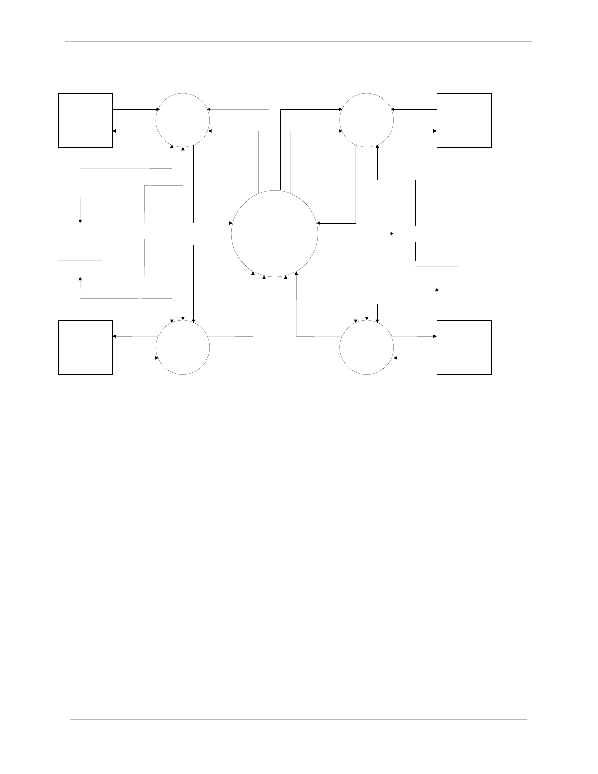
The BECO2200 DCA is an application module intended to be integrated in a modular
software environment. Figure 1 shows the data flow between the software modules in a
typical integration. As shown in this figure, the WESDAC Interface Node (WIN)
provides the only interface between the BECO2200 and the other modules in the system.
Restricted A164-0CG-1.00-2
Full
xv
Page 16
GE Energy Services
Command
Master
Station
Response
HOST
DPA
Data
Processing
Application
(DPA)
WIN Response
WIN Event
WIN Response
WIN Event
Wesmaint
Operator
Request
Display
Data
BECCO2200 DCA
Configuration Guide
Wesmaint
Display
(VT100)
DPA Data
Local I/O
DCA Data
Local
Hardware
WESDAC
Tables
Data
Request
Requested
Data
Command
Command
Local I/O
DCA
WIN
WESDAC
Command
Interface
DCA
DCA Event
DCA
Response
Node
(WIN)
Command
DCA Event
DCA
Response
Figure 1 System Overview
WIN
Data Update
DCA
BECO2200
WESDAC
Tables
BECO2200
DCA Data
Data
Request
Device
Response
BECO
Devices
xvi
A164-0CG-1.00-2 Restricted
Full
Page 17
Chapter 1: Configuration Tables
The BECO2200 DCA configuration contains all of the data structures necessary to configure an
RTU to communicate with BECO2200 slave devices.
1.1 BECO2200 DCA Configuration Tables
There are a total of six (6) configuration tables in the BECO2200 DCA configuration.
Each table is named according to a standard convention that is used for all tables commonly
found in GE Energy Services applications. The standard naming convention dictates that the
prefix (first four characters) of the table name consist of an application descriptor. This
descriptor is an arbitrary identification code chosen by GE Energy Services to indicate the
application with which the table is associated. The application descriptor for the BECO2200
DCA is A164. The last four characters of the name describe the function of the table. For
example, A164PORT defines the characteristics of the communication ports. The purpose of
each table is described below.
TABLE NAME DESCRIPTION
A164APPL
A164PORT
A164UNIT
A164MODE
A164DVCF
A164DTBL
Restricted A164-0CG-1.00-2
Full
This table always contains a si ngle record, defining parameters that affect t he entire
operation of the BECO2200 DCA.
This table configures the communication characteristics of each serial port used.
Each record in this table defines one port.
This table defines each BECO2200 device with which the BECO2200 DCA will
communicate. Each record in this table defines a single unit.
This table defines the associated action of each Mod e Download Pseudo Control.
This table defines the set of data table records to download to a range of
BECO2200 Relays.
This table defines each data table record being written to the Data Table of the
BECO2200 Relays.
1
Page 18

GE Energy Services
Table 1 BECO2200 DCA Configuration Tables
1.2 Configuration Sequence
The following is a list of the steps required to configure the BECO2200 DCA:
1. Edit the A164 configuration. Prepare it according to the guidelines in this document and the
specific use for which the BECO2200 DCA is required.
2. Edit the configuration for all other applications that will run on the product. Prepare them
according to their own configuration guides.
3. Generate the configuration and download it to the product using the GE Energy Services
Configuration System provided. The list of applications to be compiled must include A164.
4. Restart the product. The BECO2200 DCA will check the validity of its configuration
parameters and begin its initialization. If it determines that a configuration parameter is
incorrect or encounters an error during its initialization, it will log a message to the
WESMAINT Error Log and then, depending on the severity of the error, terminate or
continue with its run-time function. Self-termination of the BECO2200 DCA prevents it from
running using invalid data.
5. Check for error messages. Log into the WESMAINT maintenance interface, select the
System Functions item from the Main Menu, and then select the Error Log item from the
System Functions Menu. If any error messages are displayed, correct the problem as
described in Appendix A: Messages Logged by the BECO2200 , and repeat steps 3 through 5.
Configuration is complete when the BECO2200 DCA has successfully validated all
configuration parameters.
BECCO2200 DCA
Configuration Guide
2
A164-0CG-1.00-2 Restricted
Full
Page 19
Chapter 2: Configuring Win for the
BECO2200 DCA
This chapter describes how to configure the WESDAC Interface Node (WIN) for the BECO2200
DCA. The application number for WIN is B008. Refer to the WIN User’s Configuration Guide
for more information on how to configure WIN. The functionality of all points required by the
BECO2200 DCA is defined in the BECO2200 DCA Functional Specification.
2.1 WESDAC Point Allocation
WESDAC data point allocation is accomplished by specifying the required number of points in
the WIN configuration tables. Any points allocated to the BECO2200 DCA are maintained
solely by the BECO2200 DCA. This means the BECO2200 DCA is the only application that
may modify the value or the status of those points. All points allocated to the BECO2200 DCA
are initialized to off-line and not communicating. If the WESDAC table is in NVRAM, points
are initialized to the current value (state) in NVRAM. If the WESDAC table is in RAM, the
points are initialized to zero (off).
WESDAC DATA TYPE
Binary Inputs 42
Number of points required
BECO 2200 M-0420
Binary Outputs 44+MDPC
Counters 38
Analog Input 281
Analog Outputs 78
Device Status 1
Table 2 Required Points BECO2200 Device
Restricted A164-0CG-1.00-2
Full
3
Page 20

BECCO2200 DCA
GE Energy Services
☞
☞NOTE: The actual number of Binary Output points required must be incremented
☞☞
by the number of Mode Download Pseudo Controls configured.
Configuration Guide
2.1.1 Binary Inputs
When communication is established with a device and valid data is returned for the binary input
point, the point is turned on-line and communication OK. If communication between the device
and the point fails, all binary input points associated with the device will be set off-line and
communication failed.
2.1.2 Binary Outputs
On startup, all pseudo controls associated with a valid device and all Mode Download Pseudo
Controls are placed on-line and communication OK. When communication is established with a
device, the remaining binary outputs are set on-line and communication OK. If communication
between the device and the points fails, all binary output points, excluding pseudo controls, will
be set off-line and communication failed.
2.1.3 Counters
When communication is established with a device and valid data is returned for the counter, the
point is turned on-line and communication OK. If communication between the device and the
point fails, all counters associated with the device will be set off-line and communication failed.
2.1.4 Analog Inputs
When communication is established with a device and valid data is returned for the analog input
point, the point is turned on-line and communication OK. If communication between the device
and the point fails, all analog input points associated with the device will be set off-line and
communication failed.
2.1.5 Analog Outputs
On startup, all analog outputs associated with a valid device are placed on-line and
communication OK. If communication between the device and the point fails, all analog output
points associated with the device will be set off-line and communication failed.
2.1.6 Device Status
When communication is established with a device, the device status point is set on-line and
communication OK. If communication between the device and the point fails, the device status
point will be set off-line and communication failed.
4
A164-0CG-1.00-2 Restricted
Full
Page 21

Chapter 3: Configuring the A164APPL
Table
This chapter describes the configurable parameters in the Configuration Table (A164APPL).
3.1 General Information
The A164APPL table provides information for the overall application functionality. The table
must contain only one record.
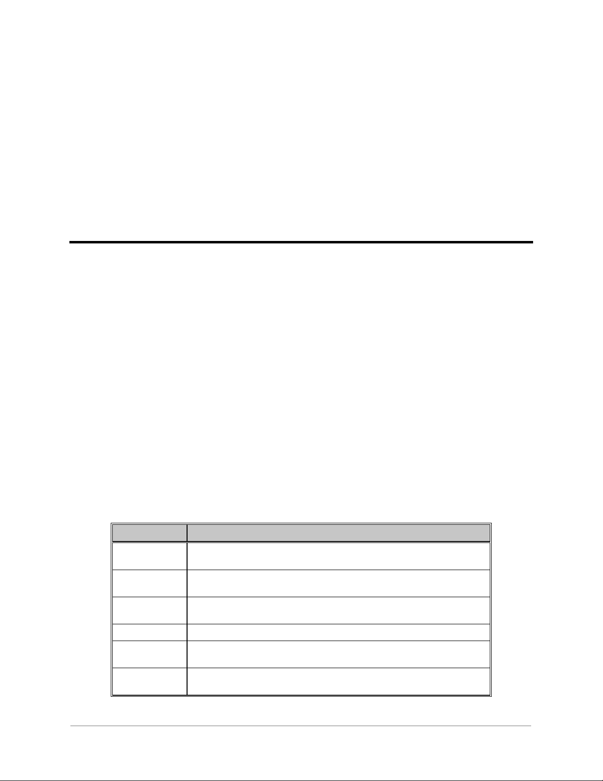
3.2 Description of Fields
Where applicable, Table 3 describes the field name, range, special case, and typical value for
each field of the A164APPL table. Following the table is a textual description of each field’s
meaning.
Field Range Special Typical
DCA Index Index into the WIN
CFG_DCA table
Reply Buffer Size
Adjustment
SOE Buffer Size
Adjustment
SOE Bu ffer Overflow
Option
Device Event Response
Time
0..65535 N/A 2 * the number of devices configured
0..65535 N/A 100
0 - Overwrite Oldest
1 - Discard Newest
0..65535 N/A 1000
N/A N/A
N/A 0 - Overwrite Oldest
Table 3 BECO2200 DCA A164APPL Configuration Table
Restricted A164-0CG-1.00-2
Full
5
Page 22

BECCO2200 DCA
GE Energy Services
3.2.1 DCA Index
This parameter specifies the WIN DCA index of the BECO2200 DCA application in the WIN
CFG_DCA table. The index is zero based. This parameter will be automatically assigned by
ConfigPro.
3.2.2 Reply Buffer Size Adjustment
This parameter specifies an increment to the total number of reply buffers allocated by the
BECO2200 DCA. The BECO2200 DCA will allocate, at a minimum, two (2) reply buffers for
each device configured. The configured adjustment will be added to this total. The number of
extra reply buffers should increase in proportion to the baud rate selected, and the frequency of
polling for each device.
☞
☞NOTE: This parameter affects the RAM requirements of the BECO2200 DCA. By
☞☞
decreasing this parameter, more RAM will be made available to other
applications running in the system.
Configuration Guide
3.2.3 SOE Buffer Size Adjustment
This parameter specifies an increment to the total number of SOE buffers allocated by the
BECO2200 DCA. The BECO2200 DCA will allocate, at a minimum, one (1) SOE Buffer for
each Digital Input point configured. The configured adjustment will be added to this total. The
number of extra reply buffers should increase in proportion to the expected event reporting of the
BECO2200 devices (the more events reported by the BECO2200 devices, the more buffers are
required to sort the information).
☞
☞NOTE: This parameter affects the RAM requirements of the BECO2200 DCA. By
☞☞
decreasing this parameter, more RAM will be made available to other
applications running in the system.
3.2.4 SOE Buffer Overflow Option
This parameter indicates what the BECO2200 DCA should do if the time sorted SOE list
becomes full. The DCA can be configured to either overwrite the oldest event in the list or to
discard the newest event.
6
A164-0CG-1.00-2 Restricted
Full
Page 23

BECCO2200 DCA
Configuration Guide
GE Energy Services
3.2.5 Device Event Response Time
This parameter specifies the maximum time required by a BECO2200 device to recognize and to
be able to report an event. This parameter is used to determine what SOE event in the system is
the oldest, in order to sort and distribute the time-tagged binary input data accurately.
Event Occurs at Device Event Buffered at Device Time ➙
T1 T2
In the above figure, it takes the BECO2200 device t2-t1 units of time to recognize and buffer
the event data. If the BECO2200 DCA had polled the device at time T, which was after t1 but
prior to time t2, no event data would have been reported, event though an event has occurred.
The BECO2200 DCA will, therefore, distribute time-sorted SOE events up to the time T- (t2-
t1), instead of up to the time T.
Restricted A164-0CG-1.00-2
Full
7
Page 24

GE Energy Services
BECCO2200 DCA
Configuration Guide
8
A164-0CG-1.00-2 Restricted
Full
Page 25

Chapter 4: Configuring the A164PORT
Table
This chapter describes the configurable parameters in the Communication Port Configuration
Table (A164PORT).
4.1 General Information
The A164PORT table provides information for the operation of the BECO2200 DCA’s
communication port(s). One record is required for every communication port configured.
4.2 Description of Fields
Where applicable, Table 4 describes the field name, range, special case, and typical value for
each field of the A164PORT table. Following the table is a textual description of each field’s
meaning.
Table 4 BECO2200 DCA A164PORT Configuration Table
Field Range Special Typical
Communication Port
Name
Communication Port
Parity
Baud rate 110, 300, 600, 1200,
RTS On Time 0..65535 Must be at least 1 if modem
Restricted A164-0CG-1.00-2
Full
COM1..COM9
COMA..COMZ
0 = None
1 = Even
2 = Odd
2400, 4800, 9600
COM0 is typically reserved for
WESMAINT
N/A 1 = Even Parity
N/A 4800 or 9600
signals are used
COM1
N/A
9
Page 26

GE Energy Services
BECCO2200 DCA
Configuration Guide
Field Range Special Typical
RTS Off Time 0..65535 Must be at least 1 character time
if modem signals are used
Intercharacter Timeout
(milliseconds)
Remote Reply Timeout
(milliseconds)
Line Idle Time
(milliseconds)
Retries Before Failure 0..65535 N/A 3
Failures Before Off-line 1..255 N/A 3
Number of Devices on
Port
one character time to
65535 ms
255 character times to
4294967295 ms
0..65535 N/A N/A
1 to the number of
A164UNIT records
N/A 2 character times
N/A 500 character times
N/A N/A
2 character times
4.2.1 Communication Port Name
This parameter specifies the communication port name string to be used for communications.
The range of valid port names is dependent on the hardware platform within which the
BECO2200 DCA resides.
4.2.2 Communication Port Parity
This parameter specifies the communication Parity of the configured port. Parity can be
configured as Even, Odd, or None. The default parity is Even.
4.2.3 BAUD Rate
This parameter specifies the communication BAUD rate for the configured port.
4.2.4 RTS On Time
This parameter specifies the time, in milliseconds, that the RTS line will be asserted prior to the
data transmission. The value configured here will be dependent on the speed and the type of
communication hardware used. Refer to Table 5 for a list of character times at the supported
BAUD rates.
☞
☞ NOTE: If either RTS On Time or the RTS Off Time are configured to be non-
☞☞
zero, the RTS On Time must be configured to at least 1 ms.
If modem signals are not desired, set both the RTS On Time and RTS Off
Time to 0.
10
A164-0CG-1.00-2 Restricted
Full
Page 27

BECCO2200 DCA
Configuration Guide
300 34
600 17
1200 9
2400 5
4800 3
9600 2
Table 5 Character Times at the Supported BAUD Rates
GE Energy Services
4.2.5 RTS Off Time
This parameter specifies the time, in milliseconds, that the RTS line will remain asserted after
the last character has entered the SIO output buffer. The value configured here will be dependent
on the speed and the type of communication hardware used. Refer to Table 5 for a list of
character times at the supported baud rates.
☞
☞NOTE: If either RTS On Time or the RTS Off Time are configured to be non-
☞☞
zero, the RTS Off Time must be configured to at least one character time.
If modem signals are not desired, set both the RTS On Time and RTS Off
Time to 0.
4.2.6 Intercharacter Timeout
This parameter specifies the maximum time, in milliseconds, that the BECO2200 DCA should
wait for the next character in the reply message. The value configured here will be dependent on
the speed and the type of communication hardware used, and must be at least one character time.
Refer to Table 5 for a list of character times at the supported baud rates.
☞
☞NOTE: Since the BECO2200 DCA uses the Intercharacter Timeout to determine
☞☞
the end of a variable length message, this parameter should be configured
to no more than 2 to 5 character times. Configuring this value with too
large of a value may impede the speed at which the BECO2200 DCA polls
the devices.
4.2.7 Remote Reply Timeout
This parameter specifies the maximum time, in milliseconds, that the BECO2200 DCA should
wait for the receipt of a complete device response. The value configured here will be dependent
on the speed and the type of communication hardware used. The value must be large enough to
receive the maximum message length possible from the BECO2200 device. The maximum
message length is 255 characters. Refer to Table 5 for a list of character times at the supported
baud rates.
Restricted A164-0CG-1.00-2
Full
11
Page 28

BECCO2200 DCA
GE Energy Services
Configuration Guide
4.2.8 Line Idle Time
This parameter specifies the minimum time, in milliseconds, that the communication line should
remain idle between the end of a response from a BECO2200 device and the beginning of the
next transmission from the BECO2200 DCA.
4.2.9 Retries Before Failure
This parameter specifies the number of automatic retries that can be conducted by the
BECO2200 DCA on a single transaction (scan/response). For every given transaction, the scan
can be retried this number of times in the event of a data link error. If no response is received
that passes the data link error check within the number of retries configured, the transaction is
considered failed.
4.2.10 Failures Before Off-line
This parameter specifies the number of consecutive transactions that must fail before a
BECO2200 device is considered off-line.
4.2.11 Number of Devices on Port
This parameter specifies the number of devices to communicate on this port. This is configured
as a range of records in the A164PORT table. For example, if the first A164PORT record has
four devices and the second A164PORT record has three devices, the first four devices
configured in the A164PORT table will communicate on the first port, and the next three
devices configured in the A164UNIT table will communicate on the second port.
12
A164-0CG-1.00-2 Restricted
Full
Page 29

Chapter 5: Configuring the A164UNIT
Table
This chapter describes the configurable parameters in the Unit Configuration Table
(A164UNIT).
5.1 General Information
The A164UNIT table provides information about each device to which the BECO2200 DCA
will be communicating. One record is required for every BECO2200 device in the system.
5.2 Description of Fields
Where applicable, Table 6 describes the field name, range, special case, and typical value for
each field of the A164UNIT table. Following the table is a textual description of each field’s
meaning.
Table 6 BECO2200 DCA A164UNIT Configuration Table
Field Range Special Typical
Unit Remote Address -1..255 -1 for Spare Device N/A
Unit Type 0 -BECO2200-M-0420 N/A N/A
Type 0 Read Interval
(seconds)
Type 1 Read Interval
(seconds)
Restricted A164-0CG-1.00-2
Full
< 0 - Demand Only
= 0 - Continuous
> 0 - Interval
< 0 - Demand Only
= 0 - Continuous
> 0 – Interval
N/A 10
N/A 10
13
Page 30

GE Energy Services
BECCO2200 DCA
Configuration Guide
Field Range Special Typical
Type 2 Read Interval
(seconds)
Type 3 Read Interval
(seconds)
Type 4 Read Interval
(seconds)
Type 5 Read Interval
(seconds)
Type 6 Read Interval
(seconds)
Type 7 Read Interval
(seconds)
Type 8 Read Interval
(seconds)
< 0 - Demand Only
= 0 - Continuous
> 0 - Interval
< 0 - Demand Only
= 0 - Continuous
> 0 - Interval
< 0 - Demand Only
= 0 - Continuous
> 0 - Interval
< 0 - Demand Only
= 0 - Continuous
> 0 - Interval
< 0 - Demand Only
= 0 - Continuous
> 0 - Interval
< 0 - Demand Only
= 0 - Continuous
> 0 - Interval
< 0 - Demand Only
= 0 - Continuous
> 0 - Interval
N/A 10
Use Type 7 Read
Instead
N/A 10
N/A 10
N/A 10
N/A 10
N/A 10
-1
Time Synchronization
Interval (seconds)
£ 0 - Demand Only
> 0 - Interval
N/A 600
5.2.1 Remote Address
This parameter specifies the remote address programmed at the unit. Each unit on the same
communication port must be given a unique address. -1 is used to indicate a SPARE device.
Spare devices are allocated WESDAC points, as described in Chapter 2: but no communication
is ever initiated to the device.
5.2.2 Unit Type
This parameter specifies the type of unit. Only BECO2200-M-0420 Control Relay is supported.
5.2.3 Type 0 Read Interval
This parameter specifies, in seconds, the minimum interval between Type 0 Read requests issued
to the device. A negative number configured indicates that no timed scans of this type are
required for this device. The device may, at any time, be scanned through the activation of the
Type 0 Read Pseudo Control.
14
A164-0CG-1.00-2 Restricted
Full
Page 31

BECCO2200 DCA
Configuration Guide
GE Energy Services
5.2.4 Type 1 Read Interval
This parameter specifies, in seconds, the minimum interval between Type 1 Read requests issued
to the device. A negative number configured indicates that no timed scans of this type are
required for this device. The device may, at any time, scanned through the activation of the Type
1 Read Pseudo Control.
5.2.5 Type 2 Read Interval
This parameter specifies, in seconds, the minimum interval between Type 2 Read requests issued
to the device. A negative number configured indicates that no timed scans of this type are
required for this device. The device may, at any time, be scanned through the activation of the
Type 2 Read Pseudo Control.
5.2.6 Type 3 Read Interval
This parameter specifies, in seconds, the minimum interval between Type 3 Read requests issued
to the device. A negative number configured indicates that no timed scans of this type are
required for this device. The device may, at any time, be scanned through the activation of the
Type 3 Read Pseudo Control.
☞
☞NOTE: Use Type 7 Read for Consecutive Status instead of Type 3 Read.
☞☞
5.2.7 Type 4 Read Interval
This parameter specifies, in seconds, the minimum interval between Type 4 Read requests issued
to the device. A negative number configured indicates that no timed scans of this type are
required for this device. The device may, at any time, be scanned through the activation of the
Type 4 Read Pseudo Control.
5.2.8 Type 5 Read Interval
This parameter specifies, in seconds, the minimum interval between Type 5 Read requests issued
to the device. A negative number configured indicates that no timed scans of this type are
required for this device. The device may, at any time, be scanned through the activation of the
Type 5 Read Pseudo Control.
5.2.9 Type 6 Read Interval
This parameter specifies, in seconds, the minimum interval between Type 6 Read requests issued
to the device. A negative number configured indicates that no timed scans of this type are
required for this device. The device may, at any time, be scanned through the activation of the
Type 6 Read Pseudo Control.
Restricted A164-0CG-1.00-2
Full
15
Page 32

BECCO2200 DCA
GE Energy Services
Configuration Guide
5.2.10 Type 7 Read Interval
This parameter specifies, in seconds, the minimum interval between Type 7 Read requests issued
to the device. A negative number configured indicates that no timed scans of this type are
required for this device. The device may, at any time, be scanned through the activation of the
Type 7 Read Pseudo Control.
☞
☞NOTE: Do not use Type 3 Read if Type 7 is enabled.
☞☞
5.2.11 Type 8 Read Interval
This parameter specifies, in seconds, the minimum interval between Type 8 Read requests issued
to the device. A negative number configured indicates that no timed scans of this type are
required for this device. The device may, at any time, be scanned through the activation of the
Type 8 Read Pseudo Control.
5.2.12 Time Synchronization Interval
This parameter specifies, in seconds, the minimum interval between Time Synchronization
requests issued to the device. A number less than or equal to zero indicates that no timed scans of
this type are required for this device. The device may, at any time, be scanned through the
activation of the Set Time Pseudo Control.
16
A164-0CG-1.00-2 Restricted
Full
Page 33

Chapter 6: Configuring the A164MODE
Table
This chapter describes the configurable parameters in the Mode Download Pseudo Control Table
(A164MODE).
6.1 General Information
The A164MODE table defines the associated action of each Mode Download Pseudo Control
(MDPC). One record is required for every Mode Download Pseudo Control in the system.
As shown in Figure 2: Relationship of the A164MODE, A164DVCF, A164UNIT, and the
A164DTBL tables, the size of each table is defined by how it is individually configured.
Restricted A164-0CG-1.00-2
Full
17
Page 34

GE Energy Services
BECCO2200 DCA
Configuration Guide
A164UNIT
First Device
A164MODE
1st MDPC
First DV CF
Number of DVCFs
2nd MDPC
First DV CF
Number of DVCFs
...
'n'th MDPC
First DV CF
Number of DVCFs
A164DVCF
1st Dev i c e /C fg
First Unit
Number of Units
First Data Rec ord
Number of Data Records
2nd Device/Cfg
First Unit
Number of Units
First Data Rec ord
Number of Data Records
...
'n'th Device/Cfg
First Unit
Number of Units
First Data Rec ord
Number of Data Records
Second Device
Third Device
...
'n'th Device
A164DTBL
1st Datal Rec.
Offset Value
2nd Data Rec.
Offset Value
3rd Data Rec.
Offset Value
...
'n'th Data Rec.
Offset Value
Figure 2 Relationship between A164MODE, A164UNOT. And A164FTBL Tables
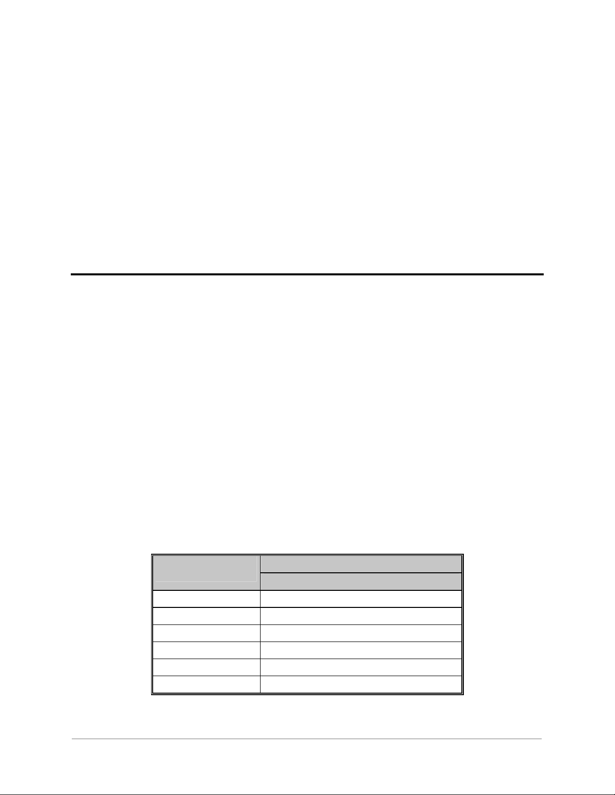
6.2 Description Of Fields
Where applicable, Table 7 gives an overview of each field of the A164MODE table. Following
the table is a textual description of each field’s meaning.
Field Name Range Special Case Typical Value
First DVCF (Indexes A164DVCF) N/A N/A
Number of DVCF 00..65535 00 = Spare N/A
Table 7 BECO2200 DCA A164MODE Configuration Table
6.2.1 First DVCF
This parameter specifies the first Device/Configuration Map (DVCF) record to execute for this
Mode Download Pseudo Control. The First DVCF and the Number of DVCF must specify a
valid range of records in the A164DVCF table.
18
A164-0CG-1.00-2 Restricted
Full
Page 35

BECCO2200 DCA
Configuration Guide
GE Energy Services
6.2.2 Number of DVCF
This parameter specifies the number of Device/Configuration Map records to execute for this
Mode Download Pseudo Control. The First DVCF and the Number of DVCF must specify a
valid range of records in the A164DVCF table.
☞
☞NOTE: Configuring this parameter to 00 indicates a spare mode download pseudo
☞☞
control.
Restricted A164-0CG-1.00-2
Full
19
Page 36

GE Energy Services
BECCO2200 DCA
Configuration Guide
20
A164-0CG-1.00-2 Restricted
Full
Page 37

Chapter 7: Configuring the A164DVCF
Configuration Table
This chapter describes the configurable parameters in the Device/Configuration Map Table
(A164DVCF).
7.1 General Information
The configuration of this table defines the set of data records to download to a range of
BECO2200 Multifunction Relay M-0420. Each record in the A164DVCF table defines a set of
data records to be downloaded to a range of BECO2200 units.
7.2 Description of Fields
Where applicable, Table 8 describes the field name, range, special case, and typical value for
each field of the A164DVCF table. Following the table is a textual description of each field’s
meaning.
Field Range Special Typical
First Unit (Indexes A164UNIT) N/A N/A
Number of Units 1..65535 N/A N/A
First Data Record (Indexes A164DTBL) N/A N/A
Number of Data Records 1..65535 N/A N/A
Table 8 BECO2200 DCA A164DVCF Configuration Table
Restricted A164-0CG-1.00-2
Full
21
Page 38

BECCO2200 DCA
GE Energy Services
Configuration Guide
7.2.1 First Unit
This parameter specifies the first unit to which this set of data records will be downloaded. The
First Unit must specify a valid range of records in the A164UNIT.
7.2.2 Number of Units
This parameter specifies the number of units to which this set of data records will be
downloaded. The Number of Units must specify a valid range of records in the A164UNIT.
7.2.3 First Data Record
This parameter specifies the first data record of this set. The First Data Record must specify a
valid range of records in the A164DTBL table.
7.2.4 Number of Data Records
This parameter specifies the number of data records contained in this set. The Number of Data
Records must specify a valid range of records in the A164DTBL table.
22
A164-0CG-1.00-2 Restricted
Full
Page 39

Chapter 8: Configuring the A164DTBL
Configuration Table
This chapter describes the configurable parameters in the Data Records Table (A164DTBL).
8.1 General Information
The A164DTBL table provides information on each data record being written to the data Table
of the BECO2200 M-0420 Multifunction Relay. Each record defines a value, table type, and the
table point number that value will be written to in the data table.
8.2 Description of Fields
Where applicable, Table 9 describes the field name, range, special case, and typical value for
each field of the A164DTBL table. Following the table is a textual description of each field’s
meaning.
Field Range Special Typical
Table Type 00..8 N/A N/A
Point Number 00..255 N/A N/A
Data Value -32768..32767 N/A N/A
Table 9 BECO2200 DCA A164DTBL Configuration Table
Restricted A164-0CG-1.00-2
Full
23
Page 40

BECCO2200 DCA
GE Energy Services
Configuration Guide
8.2.1 Table Type
This parameter specifies the table type of the BECO2200 to write the data value. Valid Type
number is zero (0), one (1), two (2), and eight (8).
8.2.2 Point Number
This parameter specifies the point number of the table type of the BECO2200 to write the data
value. For M-0420 relay the valid points are as follows:
• Type 0: Points 14-23,26-28,70-73
• Type 1: Points 0-17,19,21-26 ,28-31
• Type 2: Points 1-9,13-18,20-23,25-28,30-32,34,38-41,45-52,57-65,69
• Type 8: Points 5
8.2.3 Data Value
This parameter specifies the value to be written to the data table of the BECO2200 Multifunction
Relay.
☞
☞NOTE: The configured value is the value that will be written to the unit. No
☞☞
scaling by the BECO2200 DCA will occur.
24
A164-0CG-1.00-2 Restricted
Full
Page 41

Appendix A:Messages Logged by the
BECO2200 DCA
This appendix describes all fatal, error, warning, and information messages logged by the
BECO2200 DCA to the WESMAINT Error Log. This appendix also provides an explanation of
all output request return codes.
Messages logged to the WESMAINT Error Log by the BECO2200 DCA will be pre- pended
with a process name. This name will be one of the following:
A164:
or
A164-<x>-<y>:
where: <x> represents the process type (C,P,M,D)
<y> represents the process invocation number
A.1 Fatal Error Messages
During startup, the BECO2200 DCA checks its configuration and begins its initialization. If the
BECO2200 DCA encounters errors in the configuration or the initialization that will impede the
overall functionality of the DCA, it will log an error message to the WESMAINT Error Log and
suspend.
This section contains a description of all fatal errors. Expressions in angular brackets like “<x>”,
are filled with the appropriate values by the BECO2200 DCA. Each fatal error message contains
a unique identification number, within the range of F100 through F299.
Restricted A164-0CG-1.00-2
Full
25
Page 42

BECCO2200 DCA
GE Energy Services
Configuration Guide
F100: Bad A164APPL record counts, must be 1
Cause:
• The A164APPL configuration table contained a number of records not equal to one.
Remedy:
• Review the section on configuring the A164APPL table (Chapter 3:), and ensure that the
table consists of only one record.
F101: Bad A164PORT record counts, must be > 0
Cause:
• The A164PORT configuration table contained a number of records less than one.
Remedy:
• Review the section on configuring the A164PORT (Chapter 4:), and ensure that the table
consists of one or more records.
F102: Bad A164UNIT record counts, must be > 0
Cause:
• The A164UNIT contained a number of records less than one.
Remedy:
• Review the section on configuring the A164UNIT (Chapter 5:), and ensure that the table
consists of one or more records.
F103: Bad CFG_DCA record counts, must be > 0
Cause:
• The CFG_DCA configuration table contained a number of records less than one.
Remedy:
• Review the section on configuring WIN for the BECO2200 DCA (Chapter 2:), and ensure
that the table consists of one record for every DCA and DTA in the system.
• Review the WIN User’s Configuration Guide for more information on how to configure
WIN.
F104: Invalid DCA index
Cause:
• The DCA Index configuration parameter in the A164APPL table specifies an invalid index
into the WIN CFG_DCA table.
Remedy:
• Review the section on configuring WIN for the BECO2200 DCA (Chapter 2:), and ensure
that the table consists of one record for every DCA and DTA in the system.
• Review the section on configuring the A164APPL table (Chapter 3:) and verify that the
DCA Index parameter specifies a valid index into the WIN CFG_DCA table (the index is a
zero based table offset).
26
A164-0CG-1.00-2 Restricted
Full
Page 43

BECCO2200 DCA
Configuration Guide
GE Energy Services
F105: Invalid SOE Overflow parameter
Cause:
• The SOE Buffer Overflow Option configuration parameter in the A164APPL table is neither
Overwrite Oldest (0) nor Discard Newest (1).
Remedy:
• ·Review the section on configuring the A164APPL table (Chapter 3:) and verify that the
SOE Buffer Overflow Option is configured correctly.
F106: Total # devices exceeds UNIT size
Cause:
• The sum of all BECO2200 devices specified in all records of the A164PORT table is greater
than the number of records in the A164UNIT table.
Remedy:
• Address all fatal and non-fatal error messages preceding this message.
• Review the section on configuring the A164PORT table (Chapter 4:) and verify that the
Number of Devices on Port configuration parameter in each record is correct.
• Verify the sum of all Number of Devices on Port configuration parameters is less than or
equal to the number of records in the A164UNIT table.
F107: <x> WESDAC_<y> pnts configured, <z> required
Cause:
• <x> number of WESDAC_<y> points were configured in the WIN CFG_DCA table for the
BECO2200 DCA. <z> points are required.
Remedy:
• Review the section on configuring WIN for the BECO2200 DCA (Chapter 2:) and verify
that the number of WESDAC_<y> points configured for the BECO2200 DCA is greater than
or equal to <z>.
WESDAC NUMBER DATA TYPE
WESDAC_1 Binary Input
WESDAC_2 Binary Output
WESDAC_3 Counter
WESDAC_4 Analog Input
WESDAC_5 Analog Output
WESDAC_6 Device Status
Table 10 WESDAC Number Definitions
Restricted A164-0CG-1.00-2
Full
27
Page 44

BECCO2200 DCA
GE Energy Services
Configuration Guide
F108: <x> table creation error
Cause:
• The BECO2200 DCA tried to create the <x> table in RAM, and it failed.
Remedy:
• Reduce the amount of RAM used by this and any other application residing in the system.
Parameters that affect the amount of RAM used by this application are noted in their
associated chapters.
• Upgrade the GE Energy Services product to a model with more memory.
• Call the Customer Service department and report this error.
F109: Cannot find <x> database table
Cause:
• The BECO2200 DCA requires a number of points of a certain WESDAC point type, but
cannot find the associated table, <x>.
Remedy:
• Review the section on configuring WIN for the BECO2200 DCA (Chapter 2:) and verify
that there are points of type <x> configured in one or more of the CFG_DCA records.
• Call the Customer Service department and report this error.
F110: Fatal errors exist in configuration
Cause:
• The BECO2200 DCA encountered fatal errors in the configuration.
Remedy:
• Address all fatal error messages preceding this message.
F111: Bad A164DVCF record counts, must be > 0
Cause:
• The A164DVCF configuration table contained a number of records less than one.
Remedy:
• Review the section on configuring the A164DVCF table (Chapter 7:), and ensure that the
table consists of at least zero records.
F112: Bad A164DTBL record counts, must be > 0
Cause:
• The A164DTBL configuration table contained a number of records less than one.
Remedy:
• Review the section on configuring the A164DTBL table (Chapter 8:), and ensure that the
table consists of one or more records.
28
A164-0CG-1.00-2 Restricted
Full
Page 45

BECCO2200 DCA
Configuration Guide
GE Energy Services
F120: Mode Record <x>, invalid First DVCF
Cause:
• The First DVCF record chosen for Mode Download Pseudo Control record <x> is not within
a valid range of records in the A164DVCF configuration table.
Remedy:
• Review the section on configuring the A164MODE table (Chapter 6:), and verify that the
First DVCF chosen is within a valid range of records in the A164DVCF table.
F121: Mode Record <x>, invalid Number of DVCF
Cause:
• The Number of DVCF record(s) defined for Mode Download Pseudo Control record <x> is
not within a valid range of records in the A164DVCF configuration table.
Remedy:
• Review the section on configuring the A164MODE table (Chapter 6:), and verify that the
Number of DVCF chosen is within a valid range of records in the A164DVCF table.
F122: DVCF Record <x>, invalid First Unit
Cause:
• The First Unit record defined for this Device/Configuration (DVCF) record <x> is not within
a valid range of records in the A164UNIT table.
Remedy:
• Review the section on configuring the A164DVCF table (Chapter 6: and Chapter 7:), and
verify that the First DVCF is configured within a valid range of records in the A164UNIT
table.
F123: DVCF Record <x>, invalid Number of Units
Cause:
• The Number of Units record defined for this Device/Configuration (DVCF) record <x> is not
within a valid range of records in the A164UNIT table.
Remedy:
• Review the section on configuring the A164DVCF table (Chapter 6: and Chapter 7:), and
verify that the Number of Units is configured within a valid range of records in the
BECO2200 DCA A164UNIT Configuration Table.
F124: DVCF Record <x>, invalid First Type-Point
Cause:
• The First Data record defined for this Device/Configuration (DVCF) record <x> is not within
a valid range of records in the A164DTBL configuration table.
Remedy:
• Review the section on configuring the A164DVCF table (Chapter 6:, Chapter 7: & Chapter
8:), and verify that the First Data is configured within a valid range of records in the
A164DTBL table.
Restricted A164-0CG-1.00-2
Full
29
Page 46

BECCO2200 DCA
GE Energy Services
Configuration Guide
F125: DVCF Record <x>, invalid Number of Type-Point
Cause:
• The Number of Data record defined for this Device/Configuration (DVCF) record <x> is not
within a valid range of records in the A164DTBL configuration table.
Remedy:
• Review the section on configuring the A164DVCF table (Chapter 6:, Chapter 7:, and
Chapter 8:), and verify that the Number of Data is configured within a valid range of records
in the A164DTBL table.
F200: Error <x> on win open
Cause:
• The BECO2200 DCA failed in its attempt to open a channel to WIN. The error code returned
was <x>.
Remedy:
• Call the Customer Service department and report this error.
F201: Error <x> signaling A164-D-00 process
Cause:
• The BECO2200 DCA was unable to signal one of its critical processes. The error code
returned was <x>.
Remedy:
• Call the Customer Service department and report this error.
F202: No communication ports have been started
Cause:
• No communication processes have been properly initialized. This is either due to the
configuration of the BECO2200 DCA or due to the process initialization itself.
Remedy:
• Address all fatal and non-fatal error messages preceding this message.
F203: Error <x> creating A164-<y>-<z> exchange
Cause:
• The BECO2200 DCA failed in its attempt to create the A164-<y>-<z> exchange. The error
code returned was <x>.
Remedy:
• Call the Customer Service department and report this error.
30
A164-0CG-1.00-2 Restricted
Full
Page 47

BECCO2200 DCA
Configuration Guide
GE Energy Services
F204: Error <x> spawning A164-<y>-<z> process
Cause:
• The BECO2200 DCA failed in its attempt to spawn the A164-<y>-<z> process. The error
code returned was <x>.
Remedy:
• Call the Customer Service department and report this error.
F205: Error <x> activating A164-<y>-<z> process
Cause:
• The BECO2200 DCA failed in its attempt to activate the A164-<y>-<z> process. The error
code returned was <x>.
Remedy:
• Call the Customer Service department and report this error.
F206: Process A164-<x>-<y> died while initializing
Cause:
• The A164-<x>-<y> process was deleted while initializing.
Remedy:
• Address any fatal or non-fatal errors preceding this message.
• Call the Customer Service department and report this error.
F207: Unable to allocate buffers
Cause:
• The BECO2200 DCA was unable to allocate enough memory for its internal buffers.
Effect:
• The BECO2200 DCA will be unable to communicate to any device configured.
Remedy:
• Reduce the amount of RAM used by this and any other application in the system. The
parameters that affect the amount of RAM required by this application are noted in their
associated chapters.
• Upgrade the GE Energy Services product to a model with more memory.
• Call the Customer Service department and report this error.
Restricted A164-0CG-1.00-2
Full
31
Page 48

GE Energy Services
A.2 Non-Fatal Error Messages
Non-fatal errors cause the offending process to log a message to the WESMAINT Error Log and
suspend without affecting the rest of the BECO2200 DCA. For example, if a single polling
process encounters a non-fatal error, no polling will occur on the associated communication port.
However, demand scans on the communication port will still be an available option.
This section contains a description of all these non-fatal errors. Expressions in angular brackets
like “<x>”, are filled with the appropriate values by the BECO2200 DCA. Each non-fatal error
message contains a unique identification number, within the range of E300 through E499.
E300: PORT rec <x>, invalid baud rate
Cause:
• Record <x> of the A164PORT table contains an invalid Baud Rate.
Effect:
• Communication to all BECO2200 devices configured to use this port will be unavailable.
BECCO2200 DCA
Configuration Guide
Remedy:
• Review the section on configuring the A164PORT table (Chapter 4:), and verify that the
Baud Rate configuration parameter is configured as either 110, 300, 600, 1200, 2400, 4800,
or 9600.
E301: PORT rec <x>, invalid failures before offline
Cause:
• Record <x> of the A164PORT table contains an invalid Failures Before Offline.
Effect:
• Communication to all BECO2200 devices configured to use this port will be unavailable.
Remedy:
• Review the section on configuring the A164PORT table (Chapter 4:), and verify that the
Failures Before Off-line configuration parameter is greater than zero.
E302: PORT rec <x>, num of devices exceeds UNIT
Cause:
• The Number of Devices on Port parameter in record <x> of the A164PORT table is greater
than the number of records in the A164UNIT table.
Effect:
• Communication to all BECO2200 devices configured to use this port will be unavailable.
Remedy:
• Review the section on configuring the A164PORT table (Chapter 4:), and verify that the
Number of Devices on Port is correct.
32
A164-0CG-1.00-2 Restricted
Full
Page 49

BECCO2200 DCA
Configuration Guide
GE Energy Services
E303: PORT rec <x>, configuration bad
Cause:
• The BECO2200 DCA encounter non-fatal errors in record <x> of the A164PORT table.
Effect:
• Communication to all BECO2200 devices configured to use this port will be unavailable.
Remedy:
• Address all non-fatal errors preceding this message.
E304: PORT rec <x>, invalid unit address
Cause:
• Record <x> of the A164PORT table contains an invalid Unit Address.
Effect:
• Communication to all BECO2200 devices configured to use this port will be unavailable.
Remedy:
• Review the section on configuring the A164PORT table (Chapter 4:), and verify that the
Unit Address configuration parameter is within the range of 0 through 255.
E305: UNIT rec <x>, invalid unit type
Cause:
• Record <x> of the A164UNIT table contains an invalid Unit Type.
Effect:
• Communication to this unit will be unavailable.
Remedy:
• Review the section on configuring the BECO2200 DCA A164UNIT Configuration Table
(Chapter 5:), and verify that the Unit Type is BECO2200-M-0420 (0)
E306: Unit <x> and <y>, same address on port <z>
Cause:
• Two BECO2200 devices have been configured with the same address on port <z>.
Effect:
• Communication to the two devices will be unavailable.
Remedy:
• Review the section on configuring the A164UNIT table (Chapter 5:), and verify that the
addresses of records <x> and <y>. Each unit address on a given port must be unique.
E307: UNIT rec <x>, configuration bad
Cause:
• The BECO2200 DCA encountered non-fatal errors in record <x> of the A164UNIT table.
Effect:
• Communication to this unit will be unavailable.
Restricted A164-0CG-1.00-2
Full
33
Page 50

BECCO2200 DCA
GE Energy Services
Configuration Guide
Remedy:
• Address all non-fatal errors preceding this message.
E308: PORT rec <x>, num of devices cannot = 0
Cause:
• The Number of Devices on Port parameter in record <x> of the A164PORT table is equal to
zero.
Effect:
• Communication on this port will be unavailable.
Remedy:
• Review the section on configuring the A164PORT table (Chapter 4:), and verify that the
Number of Devices on Port is correct.
E399: Non-fatal errors exist in configuration
Cause:
• The BECO2200 DCA encountered non-fatal error in its configuration.
Effect:
• The BECO2200 will be unable to communicate to some or all of the devices configured.
Remedy:
• Address all non-fatal error messages preceding this message.
E400: Error <x> opening port <y>
Cause:
• The BECO2200 DCA failed in its attempt to open the communication port <y>. The error
code returned was <x>.
Effect:
• Communication to all devices configured for this port will be unavailable.
Remedy:
• Ensure that no other application is configured to use port <y>.
• Call the Customer Service department and report this error.
E401: Error <x> setting character port
Cause:
• The BECO2200 DCA failed in its attempt to set the communication port characteristics. The
error code returned was <x>.
Effect:
• Communication to all devices configured for this port will be unavailable.
Remedy:
• Call the Customer Service department and report this error.
34
A164-0CG-1.00-2 Restricted
Full
Page 51

BECCO2200 DCA
Configuration Guide
GE Energy Services
E402: Error <x> setting SIO timers
Cause:
• The BECO2200 DCA failed in its attempt to set the communication port timers. The error
code returned was <x>.
Effect:
• Communication to all devices configured for this port will be unavailable.
Remedy:
• Call the Customer Service department and report this error.
E403: Error <x> creating A164-<y>-<z> exchange
Cause:
• The BECO2200 DCA failed in its attempt to create the A164-<z>-<z> exchange. The error
code returned was <x>.
Effect:
• Communication to all devices configured for this port will be unavailable.
Remedy:
• Call the Customer Service department and report this error.
E404: Error <x> spawning A164-<y>-<z> process
Cause:
• The BECO2200 DCA failed in its attempt to spawn the A164-<y>-<z> process. The error
code returned was <x>.
Effect:
• If <y> equals C: Communication to all devices configured for this port will be unavailable.
• If <y> equals P: No polling of devices will occur for this port. Demand scanning is
available.
Remedy:
• Call the Customer Service department and report this error.
E405: Error <x> activating A164-<y>-<z> process
Cause:
• The BECO2200 DCA failed in its attempt to activate the A164-<y>-<z> process. The error
code returned was <x>.
Effect:
• If <y> equals C: Communication to all devices configured for this port will be unavailable.
• If <y> equals P: No polling of devices will occur for this port. Demand scanning is
available.
Remedy:
• Call the Customer Service department and report this error.
Restricted A164-0CG-1.00-2
Full
35
Page 52

BECCO2200 DCA
GE Energy Services
Configuration Guide
E406: Process A164-<x>-<y> died while initializing
Cause:
• Process A164-<x>-<y> was deleted during its initialization.
Effect:
• If <y> equals C: Communication to all devices configured for this port will be unavailable.
• If <y> equals P: No polling of devices will occur for this port. Demand scanning is
available.
Remedy:
• Address any fatal or non-fatal error message preceding this message.
• Call the Customer Service Department and report this error.
E407: Error <x> signalling A164-<y>-<z> process
Cause:
• The BECO2200 DCA was unable to signal the A164-<y>-<z> process. The error code
returned was <x>.
Effect:
• If <y> equals C: Communication to all devices configured for this port will be unavailable.
• If <y> equals P: No polling of devices will occur for this port. Demand scanning is
available.
Remedy:
• Call the Customer Service Department and report this error.
E408: Unable to allocate polling list
Cause:
• The BECO2200 DCA was unable to allocate enough memory for is polling lists.
Effect:
• The BECO2200 DCA will be unable to poll any of the devices configured. Demand scanning
is available.
Remedy:
• Reduce the amount of RAM used by this and any other application in the system. The
parameters that affect the amount of RAM required by this application are noted in their
associated chapters.
• Upgrade the GE Energy Services product to a model with more memory.
• Call the Customer Service department and report this error.
E409: Error <x>, invalid start signal from Spawner
Cause:
• This process failed to receive the start signal from the BECO2200 DCA spawner. The error
code returned was <x>.
36
A164-0CG-1.00-2 Restricted
Full
Page 53

BECCO2200 DCA
Configuration Guide
Effect:
• This process will not start. The associated functionality of this process will not be available:
• A164-D-00: The Event process reports all events to WIN.
• A164-M-00: The Command process receives and interprets WIN command requests.
• A164-C-00: The Communication process transmits and receives all messages for a
single communication port.
• A164-P-00: The Poller process initiates all polling for al single communication port.
Remedy:
• Call the Customer Service department and report this error.
A.3 Warning Messages
This section describes the warning messages the BECO2200 DCA may log to the WESMAINT
Error Log. The warnings are divided into two groups: pSOS Interface Warnings and WIN
Interface Warnings. If you find any of these messages in the WESMAINT Error Log, contact the
Customer Service Department and report the message.
Expressions in angular brackets like “<x>”, are filled with the appropriate values by the
BECO2200 DCA.
pSOS Interface Warnings
The BECO2200 DCA uses a number of message exchanges and signals for inter-process
communications. If a process is unable to send or receive a message or a signal, the functionality
of the BECO2200 DCA may be compromised. pSOS exchange warnings are numbered from
W500 through W599.
W500: Error <x> on send_x to A164-D-00
W501: Error <x> on send_x to A164-C-<y>
W502: Error <x> on jam_x to A164-C-<y>
W503: Error <x> on wait_v from A164-C-<y>
W504: Error <x> signaling back response
W505: Error <x> on req_x
WIN Interface Warnings
During run-time, the BECO2200 DCA interfaces to the WESDAC Interface Node (WIN) by
writing various commands. If any of these writes fail, the command can not be passed to other
applications in the system. WIN interface warnings are numbered from W600 through W699.
W600: Error <x> on win read
W601: Error <x> on ACK/NACK win write
W602: Error <x> on DATA UPDATED CMD win write
W603: Error <x> on TIME SYNC win write
W604: Error <x> on WES<y> REST_COMM win write
W605: Error <x> on WES<y> LOSS_COMM win write
W606: Error <x> on WES<y> ON_LINE win write
W607: Error <x> on WES<y> OFF_LINE win write
GE Energy Services
Restricted A164-0CG-1.00-2
Full
37
Page 54

GE Energy Services
W608: Error <x> on WES<y> INIT_POINT win write
W609: Error <x> on WES6 CHANGE_TRANS win write
W610: Error <x> on WES6 CHANGE_FAILS win write
W611: Error <x> on WES6 CHANGE_RETRIES win write
W612: Error <x> on WES1 DATA_CHANGE win write
W613: Error <x> on WES<y> TT DATA CHANGE win write
A.4 Information Messages
Information messages are posted when the BECO2200 DCA encounters a situation where it
must, as a result, perform some action. Expressions in angular brackets like “<x>”, are filled
with the appropriate values by the BECO2200 DCA. Each information message is given a
unique identification number, within the range of I700 through I799.
I700: PORT rec <x>, invalid reply time-out
Cause:
• Record <x> of the A164PORT table contains a Remote Reply Timeout that is less than the
amount of time required to receive the maximum message length.
BECCO2200 DCA
Configuration Guide
Effect:
• The BECO2200 DCA will set this parameter to the minimum time required to receive the
maximum message length.
Remedy:
• Review the section on configuring the A164PORT table (Chapter 4:), and configure the
Remote Reply Timeout to at least the time required to receive the maximum message length.
I701: PORT rec <x>, invalid RTS on time
Cause:
• Record <x> of the A164PORT table contains a RTS On Time that is less than one.
Effect:
• The BECO2200 DCA will set this parameter to one.
Remedy:
• If modem signals are required, review the section on configuring the A164PORT table
(Chapter 4:) and verify the RTS On Time is a valid time.
• If modem signals are not required, set this parameter and the RTS Off Time to zero.
I702: PORT rec <x>, invalid RTS off time
Cause:
• Record <x> of the A164PORT table contains a RTS Off Time that is less than one character
time.
38
A164-0CG-1.00-2 Restricted
Full
Page 55

BECCO2200 DCA
Configuration Guide
GE Energy Services
Effect:
• The BECO2200 DCA will set this parameter to one character time.
Remedy:
• If modem signals are required, review the section on configuring the A164PORT table
(Chapter 4:) and verify the RTS Off Time is a valid time.
• If modem signals are not required, set this parameter and the RTS On Time to zero.
I703: PORT rec <x>, invalid intercharacter timeout
Cause:
• Record <x> of the BECO2200 DCA A164PORT Configuration Table contains an
Intercharacter Timeout that is less than one character time.
Effect:
• The BECO2200 DCA will set this parameter to one character time.
Remedy:
• Review the section on configuring the A164PORT table (Chapter 4:) and verify that the
Intercharacter Timeout is a valid time.
I704: No Configuration - deleting
Cause:
• The BECO2200 DCA could not find the A164APPL table.
Effect:
• The BECO2200 DCA will delete itself.
Remedy:
• If the BECO2200 DCA is supposed to run, verify that the A164APPL table is included in the
configuration. Also verify that the BECO2200 DCA application (A164) is included in the
configuration.
I705: PORT rec <x>, no polling required
Cause:
• All units configured for this port are either configured as spare devices, configured for no
polling, or contain invalid configurations.
Effect:
• The polling process will suspend, and no polling of devices will occur for this port. Demand
scanning is available.
Remedy:
• If polling is required by some or all the devices on this port, address all fatal and non- fatal
error messages preceding this message.
Restricted A164-0CG-1.00-2
Full
39
Page 56

GE Energy Services
A.5 Output Request Return Codes
When processing WIN output requests, the BECO2200 DCA may not be able to execute the
request. If this occurs, the BECO2200 DCA will set the status code returned with the request to
the appropriate error code, and negatively acknowledge (NACK) the control request. This
section describes the possible status codes returned.
Demand Scan Failed (0x0080)
The BECO2200 DCA was unable to successfully execute the requested Read to the device.
DO Operate Failed (0x0081)
The BECO2200 DCA failed in its attempt to issue the Control Operate request.
AO Operate Failed (0x0082)
The BECO2200 DCA failed in its attempt to issue the Analog Output request.
Download Failed (0x0083)
The BECO2200 DCA Write to IEDs request was not successful in that at least one of the writes
to a device failed.
BECCO2200 DCA
Configuration Guide
40
A164-0CG-1.00-2 Restricted
Full
Page 57

Glossary of Terms
application A piece of software (a program) consisting of one or more
processes and supporting functions.
ASCII American Standard Code for Information Interchange. A seven-
bit code that standardizes a set of characters representing letters
and numbers for international use.
Baud rate A measurement of the speed of a communications line; the
number of times a line can change state in one second; the rate at
which a signal is modulated.
Binary A number system having only two symbols (1 and 0), and where
values are expressed in the base two number system.
Bit Abbreviation of binary digit. The smallest unit of information in a
binary system. Has a value of either one (1) or zero (0).
Bits per second The speed at which a channel transmits (in a serial transmission) a
single bit. A serial transmission sends one bit at a time.
Abbreviated as bps.
Byte A group of eight adjacent bits that function as a single unit.
Defined as an octet by the International Electrotechnical
Commission (IEC).
Change of state A significant change (as defined by a particular system) in the
condition of a point being monitored, for example, a change in
flow rate, temperature, voltage, etc. Usually associated with dualstate status (that is, alarm/normal conditions). Abbreviated as
COS.
Char The name of a data-type in the C programming language. Stands
for character, or a group of eight bits that function as a single unit.
Configuration
information
Configuration
system
The data or information that defines the operational limits and
characteristics of a particular device. Depending on the device,
this information is either manually downloaded into NVRAM or
EEPROM, or is pre-programmed into EPROM.
See WESDAC Configuration System.
Restricted A164-0CG-1.00-2
Full
41
Page 58

GE Energy Services
BECCO2200 DCA
Configuration Guide
Data-collection
application
Data-translation
application
A software application that acquires data from and sends data to
various intelligent electronic devices. Abbreviated as DCA.
A software application that translates data from one form to
another (for example digital input to analog input). A data-
translation application usually has no direct interface to external
devices. Abbreviated as DTA.
Decimal A number system having ten symbols, and where values are
expressed in the base ten number system.
Hexadecimal A number system having 16 symbols, and where values are
expressed in the base 16 number system. Commonly used to
abbreviate binary data. Sometimes referred to as hex.
Hexadecimal numbers are often preceded by the prefix 0x.
Master The client or host station or computer, with which the RTU
equipment communicates. Also referred to as a host or host
computer.
Non-volatile
A semi-permanent type of data storage (memory)
random-access
memory that is backed up by batteries to maintain stored data even if
system power is lost. Can be both read and changed by the
system. Abbreviated as NVRAM.
Port An interface point connecting a communications channel and a
device.
Random-access
memory
A type of temporary data storage (memory) that can be read and
changed while the computer is in use. Data stored in random-
access memory is lost if the system loses power. Abbreviated as
RAM.
Read-only
memory
A type of permanent data storage (memory) that can be read but
not altered by the system. Data stored in read-only memory is not
affected by power loss to the system. Abbreviated as ROM.
Remote terminal
unit
A piece of equipment located at a distance from a master station
to monitor and control the status of outlying equipment, and to
communicate the information back to the master station or host.
Abbreviated as RTU.
Sequence of
events
A time-tagged change of state, logged as part of a chronological
record of significant changes in the condition of a particular point
or points being monitored. Abbreviated as SOE.
Slave See sub-remote unit.
Source code A piece of code that has not yet been compiled or assembled (that
is, it is still in the language it was programmed in) and so cannot
yet run on a machine.
Sub-remote unit A physical device (e.g., peripheral boards, D20 RTUs, non-D20
RTUs, meters, or other intelligent electronic device) that collects
data, processes it in some way, and communicates it to a master
remote unit (MRU). SRUs (also called slave units) are able to
respond to commands from MRUs.
WESDAC A module of software that manages the transfer, storage, and
42
A164-0CG-1.00-2 Restricted
Full
Page 59

BECCO2200 DCA
Configuration Guide
Interface Node manipulation of data between data- collection applications
(DCA), data-processing applications (DPA) and data-translation
applications (DTA). Abbreviated as WIN.
WESDAC
Configuration
System
A menu-oriented software program that operates on a personal
computer and allows you to download configuration information
to D20 RTUs or CPM RTUs.
GE Energy Services
Restricted A164-0CG-1.00-2
Full
43
Page 60

GE Energy Services
BECCO2200 DCA
Configuration Guide
44
A164-0CG-1.00-2 Restricted
Full
Page 61

List of Acronyms and Abbreviations
AI Analog Input
ASCII American Standard Code for Information Interchange
COS change of state
DCA data-collection application
DPA data-processing application
DTA data-translation application
DVCF device configuration map
IED intelligent electronic device
MAXRECS maximum number of records
MDPC mode download pseudo control
MMI man-machine interface
NACK negative acknowledgment
NVRAM non-volatile random-access memory
RAM random-access memory
RTS request to send
RTU remote terminal unit
SIO serial input/output
SOE sequence of events
Tx transmit
WESDAC WESDAC Data Acquisition and Control
WESMAINT WESDAC Maintenance Facility
WIN WESDAC Interface Node
Restricted A164-0CG-1.00-2
Full
45
 Loading...