

Page 1

Title pageMULTILIN B95
Pl
LISTED
52TL
IND.CONT. EQ.
E83849
GE Energy
us
BUS
Instruction manual
Plus
B95
firmware revision: 1.00
GE publication code: GEK-113629
GE Digital Energy
215 Anderson Avenue, Markham, Ontario
Canada L6E 1B3
Tel: (905) 294-6222 Fax: (905) 201-2098
Internet: http://www.gedigitalenergy.com
*1601-0015-A1*
GE Multilin's Quality
Management System is
registered to ISO 9001:2008
QMI # 005094
UL # e83849
Page 2

PROTECTION SYSTEM –
Copyright © 2012 GE Multilin Inc. All rights reserved.
Multilin B95
Multilin, Multilin B95
FlexLogic, and FlexAnalog are trademarks or registered trademarks of GE Multilin Inc.
The contents of this manual are the property of GE Multilin Inc. This documentation is
furnished on license and may not be reproduced in whole or in part without the permission
of GE Multilin. The manual is for informational use only and is subject to change without
notice.
Part number: 1601-0015-A1 (April 2012)
Plus
Bus Protection System Instruction Manual for product revision 1.00.
Plus
Bus Protection System, EnerVista, EnerVista B95
Plus
Setup,
Page 3

INSTRUCTION MANUAL
GENERAL SAFETY PRECAUTIONS - B95
Plus
• The use of Omega-level safety shoes, safety gloves, safety glasses, and protective clothing are
recommended during equipment installation, maintenance, and service.
• Failure to observe and follow the instructions provided in the instruction manual can cause
damage to the equipment and can lead to property damage, personal injury, and/or death.
• Before attempting to use the equipment, review all danger and caution indicators.
• If the equipment is used in a manner not specified by the manufacturer or functions
abnormally, proceed with caution. Otherwise, the protection provided by the equipment can be
impaired and can result in damage and/or injury.
• Hazardous voltages can cause shock, burns, or death.
• Installation/service personnel must be familiar with general device test practices and
electrical awareness. Safety precautions must be followed.
• Before performing visual inspections, tests, or periodic maintenance on this device or
associated circuits, isolate or disconnect all live circuits and sources of electric power.
• Failure to power equipment off prior to removing the power connections can lead to exposure
to dangerous voltages causing injury or death.
• All recommended equipment that can be grounded should be and must have a reliable and
uncompromised grounding path for safety purposes, protection against electromagnetic
interference, and proper device operation.
• Equipment grounds should be bonded together and connected to the facility’s main ground
system for primary power.
• Keep all ground leads as short as possible.
• The equipment ground terminal must be grounded at all times during device operation and
service.
• In addition to the safety precautions mentioned, all electrical connections made must respect
the applicable local jurisdiction electrical code.
• LED transmitters are classified as IEC 60825-1 Accessible Emission Limit (AEL) Class 1M. Class
1M devices are considered safe to the unaided eye. Do not view directly with optical
instruments.
• Before working on current transformers (CTs), short-circuit them.
FCC/Industry Canada
This device complies with Part 15 of the FCC Rules and Industry Canada rules. Operation is
subject to the following two conditions: (1) this device may not cause harmful interference, and
(2) this device must accept any interference received, including interference that may cause
undesired operation.
L’appareil conforme aux CNR d'Industrie Canada applicable aux appareils radio exempts de
licence. L'exploitation est autorisé aux deux conditions suivantes: (1) l'appareil ne doit pas
produire de brouillage, et (2) l'utilisateur de l'appareil doit accepter tout brouillage radiolectrique
subi, même si le brouillage est susceptible d'en compromettre le fonctionnement.
Page 4

Page 5

GE Energy
Plus
Multilin B95
Bus Protection
System
Table of contents
GETTING STARTED Safety words and definitions........................................................................................1
Unpacking and inspection checklist ...........................................................................1
Quick start .......................................................................................................................2
For further assistance ...................................................................................................2
PRODUCT
DESCRIPTION
INSTALLATION Installing the unit in a rack.........................................................................................19
Device overview..............................................................................................................3
FlexLogic equations ........................................................................................................................................6
HardFiber overview........................................................................................................7
Order codes .....................................................................................................................8
Specifications..................................................................................................................9
Remote resources specifications..............................................................................................................9
Protection specifications ........................................................................................................................... 10
Communications specifications ............................................................................................................. 12
Digital fault recorder specifications...................................................................................................... 13
Front panel interface ................................................................................................................................... 14
Security specifications ................................................................................................................................14
Hardware specifications ............................................................................................................................14
Test specifications.........................................................................................................................................16
Environmental specifications .................................................................................................................. 17
Approvals and certification ......................................................................................................................17
Rear terminal and port layout ...................................................................................21
Typical wiring diagram................................................................................................22
Dielectric strength .......................................................................................................23
Power supply card (slot A)...........................................................................................23
Communications card (slot C) ....................................................................................25
Main processor card (slot D).......................................................................................25
Ethernet port ................................................................................................................................................... 25
IRIG-B port ........................................................................................................................................................ 26
Process cards (slot J and optionally slot F)..............................................................27
MULTILIN B95
Plus
BUS PROTECTION SYSTEM – INSTRUCTION MANUAL v
Page 6

TABLE OF CONTENTS
ENERVISTA
SOFTWARE
Introduction...................................................................................................................29
Installing the EnerVista software ..............................................................................30
Establishing communication via USB .......................................................................31
Establishing communication via Ethernet...............................................................33
Adding sites and devices.............................................................................................34
Connecting to a device................................................................................................35
Accessing settings........................................................................................................36
Operand quick select ...................................................................................................................................36
Navigating long lists .....................................................................................................................................37
Expanding/collapsing table rows...........................................................................................................38
Viewing actual values..................................................................................................38
Viewing event records .................................................................................................38
Viewing transient records...........................................................................................39
Settings files ..................................................................................................................40
Deploying settings files to multiple devices using settings templates ..............41
Enabling the settings template in offline mode...............................................................................41
Enabling the settings template in online mode...............................................................................42
Editing a settings template .......................................................................................................................42
Adding password protection to a settings template ....................................................................43
Applying a settings template....................................................................................................................44
Removing a settings template.................................................................................................................45
Bus replica graphical editor .......................................................................................45
Securing and locking FlexLogic equations...............................................................50
Locking FlexLogic equation entries .......................................................................................................50
Locking a settings file and FlexLogic equations to a serial number ......................................51
Settings file traceability ..............................................................................................51
SETTINGS –
GENERAL
Installation.....................................................................................................................53
Power system ................................................................................................................54
User programmable self-tests...................................................................................56
COMMUNICATIONS Communications overview .........................................................................................59
Network settings ..........................................................................................................59
Ethernet..............................................................................................................................................................59
TFTP ......................................................................................................................................................................63
SNTP .....................................................................................................................................................................64
HTTP .....................................................................................................................................................................65
Viewing Ethernet actual values...............................................................................................................67
Viewing TCP/IP connection actual values ..........................................................................................68
Modbus communications............................................................................................69
Protocol...............................................................................................................................................................69
User map ...........................................................................................................................................................70
DNP communications ..................................................................................................71
Protocol...............................................................................................................................................................72
User point list ...................................................................................................................................................75
IEC 60870-5-104 communications ............................................................................76
Configuring IEC 60870-5-104 settings.................................................................................................76
Configuring IEC 60870-5-104 point lists .............................................................................................77
IEC 61850 communications ........................................................................................78
GSSE/GOOSE configuration.......................................................................................................................78
Server configuration.....................................................................................................................................92
vi MULTILIN B95
Plus
BUS PROTECTION SYSTEM – INSTRUCTION MANUAL
Page 7

TABLE OF CONTENTS
GGIO1 status configuration...................................................................................................................... 93
Viewing IEC 61850 actual values........................................................................................................... 94
Real time clock and IRIG-B..........................................................................................97
Virtual inputs.................................................................................................................99
Communication logic operands ............................................................................. 100
REMOTE RESOURCES Field units.................................................................................................................... 103
Settings ........................................................................................................................................................... 104
Auto populate .............................................................................................................................................. 105
Actual values ................................................................................................................................................ 106
FlexLogic operands ................................................................................................................................... 106
Field contact inputs .................................................................................................. 107
Settings ........................................................................................................................................................... 107
Actual values ................................................................................................................................................ 108
FlexLogic operands ................................................................................................................................... 109
Field contact inputs chatter detection.................................................................. 109
Field contact outputs................................................................................................ 111
Settings ........................................................................................................................................................... 111
Actual values ................................................................................................................................................ 112
FlexLogic operands ................................................................................................................................... 113
Field latching outputs............................................................................................... 114
Settings ........................................................................................................................................................... 114
Actual values ................................................................................................................................................ 115
FlexLogic operands ................................................................................................................................... 116
Shared inputs and outputs ...................................................................................... 117
Shared input settings ............................................................................................................................... 117
Shared input actual values .................................................................................................................... 118
Shared output settings ............................................................................................................................ 119
Shared output actual values................................................................................................................. 120
FlexLogic operands ................................................................................................................................... 120
PROTECTION Bus protection overview .......................................................................................... 121
Bus source concept................................................................................................................................... 121
Bus zone concept....................................................................................................................................... 122
Bus replica concept................................................................................................................................... 123
Bus sources ................................................................................................................ 124
General settings.......................................................................................................................................... 125
CT settings ..................................................................................................................................................... 126
Bus configuration settings ..................................................................................................................... 129
Zone trip bus settings............................................................................................................................... 133
End fault protection settings................................................................................................................. 135
Breaker failure settings ........................................................................................................................... 137
Instantaneous overcurrent settings.................................................................................................. 145
Inverse time overcurrent settings ...................................................................................................... 146
Actual values ................................................................................................................................................ 147
FlexLogic operands ................................................................................................................................... 149
Analog operands ........................................................................................................................................ 150
Voltage sources ......................................................................................................... 150
General settings.......................................................................................................................................... 151
Voltage sources settings......................................................................................................................... 152
Undervoltage settings.............................................................................................................................. 155
Actual values ................................................................................................................................................ 156
FlexLogic operands ................................................................................................................................... 158
MULTILIN B95
Plus
BUS PROTECTION SYSTEM – INSTRUCTION MANUAL vii
Page 8

TABLE OF CONTENTS
Analog operands......................................................................................................................................... 158
Bus differential........................................................................................................... 158
General settings...........................................................................................................................................160
Operating characteristic settings........................................................................................................162
Supervision settings...................................................................................................................................165
Actual values.................................................................................................................................................168
FlexLogic operands....................................................................................................................................169
Analog operands......................................................................................................................................... 170
Bus replica graphical editor .................................................................................... 170
FlexLogic ..................................................................................................................... 170
FlexLogic rules..............................................................................................................................................172
FlexLogic gates and operators.............................................................................................................173
FlexLogic equation editor........................................................................................................................174
FlexLogic timers...........................................................................................................................................174
Non-volatile latches...................................................................................................................................175
Setting group control................................................................................................ 176
Isolators ...................................................................................................................... 177
Settings............................................................................................................................................................179
Actual values.................................................................................................................................................180
FlexLogic operands....................................................................................................................................182
DIGITAL FAULT
RECORDER (DFR)
Event recorder ........................................................................................................... 183
Viewing records ...........................................................................................................................................183
Transient recorder .................................................................................................... 185
Settings............................................................................................................................................................186
Viewing records ...........................................................................................................................................190
FlexLogic operands....................................................................................................................................192
FRONT PANEL Front panel overview ................................................................................................ 193
Status LED................................................................................................................... 194
Annunciator panel..................................................................................................... 194
Operation........................................................................................................................................................194
Settings............................................................................................................................................................196
Self-test summary display operation .................................................................... 200
Bus diagram operation............................................................................................. 201
Bus source template editor ..................................................................................... 201
Dynamic symbols........................................................................................................................................203
Static symbols ..............................................................................................................................................204
Pre-configured mimic diagrams..........................................................................................................205
Metering summary.................................................................................................... 205
Display properties ..................................................................................................... 207
Phasor display............................................................................................................ 208
SECURITY User and password management .......................................................................... 209
Local and remote passwords .................................................................................. 210
Access alarms ............................................................................................................ 213
CONFIGURE
Configure FlexOperands........................................................................................... 215
FLEXOPERANDS
viii MULTILIN B95
Plus
BUS PROTECTION SYSTEM – INSTRUCTION MANUAL
Page 9

TABLE OF CONTENTS
PRODUCT
Serial number............................................................................................................. 217
INFORMATION
MAINTENANCE Test mode ................................................................................................................... 219
Self-tests ..................................................................................................................... 220
Major self-tests............................................................................................................................................ 221
Minor self-tests............................................................................................................................................ 222
FlexLogic operands ................................................................................................................................... 224
Set date and time ...................................................................................................... 226
Raw data viewer ........................................................................................................ 227
Analog inputs ............................................................................................................................................... 227
Contact and shared input/output ...................................................................................................... 228
Diagnostics.................................................................................................................................................... 230
Modbus analyzer ....................................................................................................... 232
Updating firmware.................................................................................................... 234
BUS REPLICA
APPLICATION GUIDE
Static bus arrangements ......................................................................................... 237
Dynamic bus arrangements.................................................................................... 245
Sectionalized bus........................................................................................................................................ 246
Double-bus single-breaker .................................................................................................................... 250
Main and transfer bus.............................................................................................................................. 254
Breaker bypass switches ........................................................................................................................ 259
Check zones................................................................................................................ 260
Undervoltage supervision........................................................................................ 264
Zone expansion/reduction and end fault protection ......................................... 264
Breaker failure ........................................................................................................... 265
APPENDIX Revision history ......................................................................................................... 267
Warranty..................................................................................................................... 267
MULTILIN B95
Plus
BUS PROTECTION SYSTEM – INSTRUCTION MANUAL ix
Page 10

TABLE OF CONTENTS
x MULTILIN B95
Plus
BUS PROTECTION SYSTEM – INSTRUCTION MANUAL
Page 11

GE Energy
Plus
Multilin B95
Bus Protection
System
Chapter 1: Getting started
Getting started
This section outlines the symbols used in the document, what is in the box, and general
approach to set up the Multilin B95
Plus
Bus Protection SystemTM.
DANGER:
IMPORTANT:
CAUTION:
NOTE:
Safety words and definitions
Before attempting to install or use the device, review all safety indicators in this document
to help prevent injury, equipment damage, or downtime.
The following safety and equipment symbols are used in this document.
Indicates a hazardous situation which, if not avoided, will result in death or serious
injury.
Indicates a hazardous situation which, if not avoided, could result in death or serious
injury.
Indicates a hazardous situation which, if not avoided, could result in minor or
moderate injury.
Indicates practices not related to personal injury.
Unpacking and inspection checklist
Use this procedure to unpack and inspect the B95
1. Inspect the packaging for physical damage.
2. Open it and inspect the B95
3. Check that the following items have been delivered:
– Multilin B95
– GE EnerVistaTM CD (software and documentation)
– Instruction Manual (if ordered)
–Certificate of Calibration
Plus
Bus Protection System
Plus
for physical damage.
Plus
.
MULTILIN B95
Plus
BUS PROTECTION SYSTEM – INSTRUCTION MANUAL 1
Page 12

QUICK START CHAPTER 1: GETTING STARTED
–Test Report
– EC Declaration of Conformity
4. View the rear nameplate of the product and verify that the correct model has been
delivered.
5. For product information, instruction manual updates, and software updates, visit the
GE Multilin website at http://gedigitalenergy.com/multilin.
6. If any of the contents listed are missing or there is physical damage to the product,
contact GE Digital Energy immediately using the contact information in the For
Further Assistance section.
Quick start
The process for installing the unit is as follows:
• Install the unit in a rack (see Installing the Unit in a Rack)
• Connect the power supply and wire the unit (see Typical Wiring Diagram)
• Install the EnerVista software on a computer (see Installing the EnerVista Software)
• Connect the computer to the unit using a USB or Ethernet cable. Use of a USB cable is
recommended for setup because of ease of use, after which you can switch to
Ethernet for faster communications. (See Establishing Communication via USB and
see Establishing Communication via Ethernet. Setup using the USB cable is
documented.)
• Configure the unit by accessing the Settings panels in the Online Window area of the
EnerVista software. Use this document for information as you work through the
settings panels.
• Configure user access (see Security)
If a device is not available, one can still familiarize oneself by installing EnerVista software
and experimenting with the Offline Window features, skipping the steps involving a device.
Note that the chapters starting with Settings - General largely follow the structure
displayed in the software.
For further assistance
For product support, contact the information and call center as follows:
GE Digital Energy
215 Anderson Avenue
Markham, Ontario
Canada L6E 1B3
Telephone: 1-905-294-6222
Toll-free: 1-800-547-8629
Fax: 1-905-201-2098
E-mail: multilin.tech@ge.com
Website: http://www.gedigitalenergy.com/multilin/
Comments about new features or modifications for specific requirements are welcome.
2 MULTILIN B95
Plus
BUS PROTECTION SYSTEM – INSTRUCTION MANUAL
Page 13
GE Energy
Plus
Multilin B95
Bus Protection
System
Chapter 2: Product description
Product description
This chapter provides an overview and technical specifications of the Multilin B95
Protection System.
Device overview
The Multilin B95
currents connected to the bus and when it detects a fault on the bus, it sends signals to
isolate the bus. When there is a fault on a bus, the entire bus goes down, making the
Plus
B95
Process Bus product family to provide a distributed, low impedance, current differential
protection solution for medium and high voltage large and reconfigurable buses.
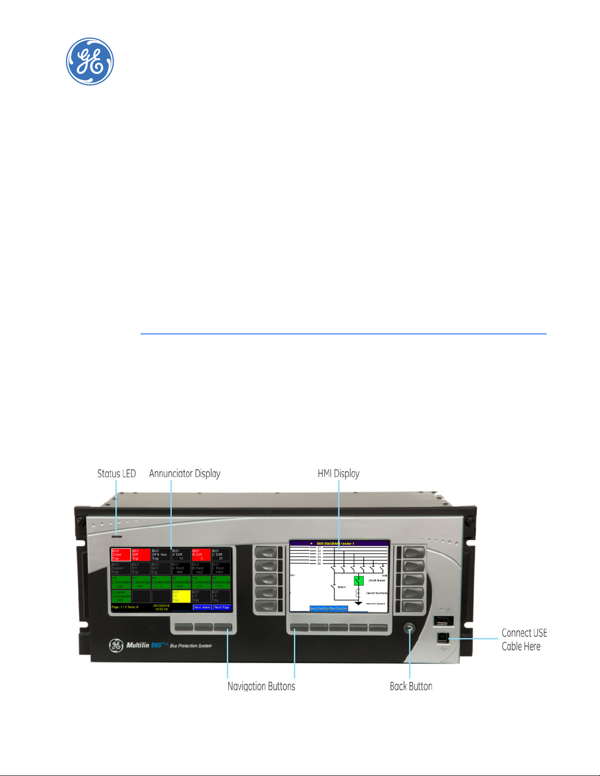
Figure 1: Front view
crucial. The B95
Plus
Plus
Bus
Bus Protection System is a relay to detect faults on a bus. It measures
Plus
extends the UR
Plus
-series product family and the HardFiberTM
MULTILIN B95
Plus
BUS PROTECTION SYSTEM – INSTRUCTION MANUAL 3
Page 14

DEVICE OVERVIEW CHAPTER 2: PRODUCT DESCRIPTION
The protection system consists of a distributed process interface (data acquisition and
tripping) architecture using GE HardFiber
the B95
The functions of the B95
Plus
.
Plus
include the following:
Bricks, with centralized processing performed by
• Multi-zone differential protection with both restrained (dual-slope percent or biased)
and unrestrained (unbiased or instantaneous) functions incorporated. Differential
protection is fast and secure. Security is achieved by using a reliable current
transformer (CT) saturation detection algorithm and a directional comparison
operating principle. Security is further enhanced by support for redundant process
interface (Bricks). Three-phase tripping is supported; differential protection operands
are provided for individual phase tripping.
• Interfaces with up to eight HardFiber Bricks per process card. The B95
Plus
can contain
one or two process cards.
• Supports up to 12 bus sources per process card. A single bus source is used to
interface a network element connection to the bus, such as a feeder, line, transformer,
capacitor, or reactor. A single bus source is used to interface a bus tie disconnect. Two
bus sources are used to interface a bus tie breaker.
• Dynamic bus replica functionality and multi-zone protection is supported allowing
application of the B95
Plus
to multi-section reconfigurable buses. A zone expansion/
contraction to an open breaker feature is included.
• Check-zone functionality can be configured by programming one of the differential
zones to enclose the entire bus.
• Supports up to two undervoltage functions per process card for differential protection
supervision purposes.
• End-fault protection (dead-zone protection) is provided for each bus source.
• A breaker fail function with three-phase tripping support and fast resetting current
detectors is provided for each bus source.
• An instantaneous phase overcurrent function is provided for each bus source for
possible supervision purposes.
• An inverse time phase overcurrent function is provided for each bus source for
possible backup protection.
• An isolator position resolution and monitoring feature monitors 48 isolators per
process card.
• A CT trouble monitoring function is provided for each zone of differential protection.
Voltage and current metering are built into the relay as standard features, as fundamental
frequency-only root mean square (RMS) scaled magnitude and angle (phasor).
Diagnostic features include an event recorder capable of storing 4,096 time-stamped
events plus 4,096 time-stamped events per process card. Oscillography is userprogrammable as to sampling rate (up to 128 samples per cycle), content, writing mode,
and record length. The internal clock used for time stamping can be synchronized with an
IRIG-B signal or using the simple network time protocol (SNTP) over Ethernet. This precise
time stamping allows the sequence of events to be determined throughout the system.
Events can also be programmed using FlexLogic
TM
equations to trigger oscillography data
capture, which can be set to record the measured parameters before and after the event
for viewing on a computer. These tools significantly reduce troubleshooting time and
simplify report generation in the event of a system fault.
On the communications card, either of the two Ethernet ports can be used for supervisory
control and data acquisition (SCADA) access, the programming of settings, and the
monitoring of actual values. These two Ethernet ports have both 100Base-TX and
4 MULTILIN B95
Plus
BUS PROTECTION SYSTEM – INSTRUCTION MANUAL
Page 15
CHAPTER 2: PRODUCT DESCRIPTION DEVICE OVERVIEW
100Base-FX interfaces, and they can be used to provide fast, reliable communications in
noisy environments. These ports support TFTP, SNTP, IEC 61850, Modbus/TCP, and IEC
60870 protocols. DNP 3.0 and IEC 60870 cannot be enabled at the same time.
A third Ethernet port supports engineering access using the EnerVista B95
Plus
SetupTM
software.
The B95
Plus
intelligent electronic devices (IEDs) use Flash memory technology that allows
field upgrading as new features are added.
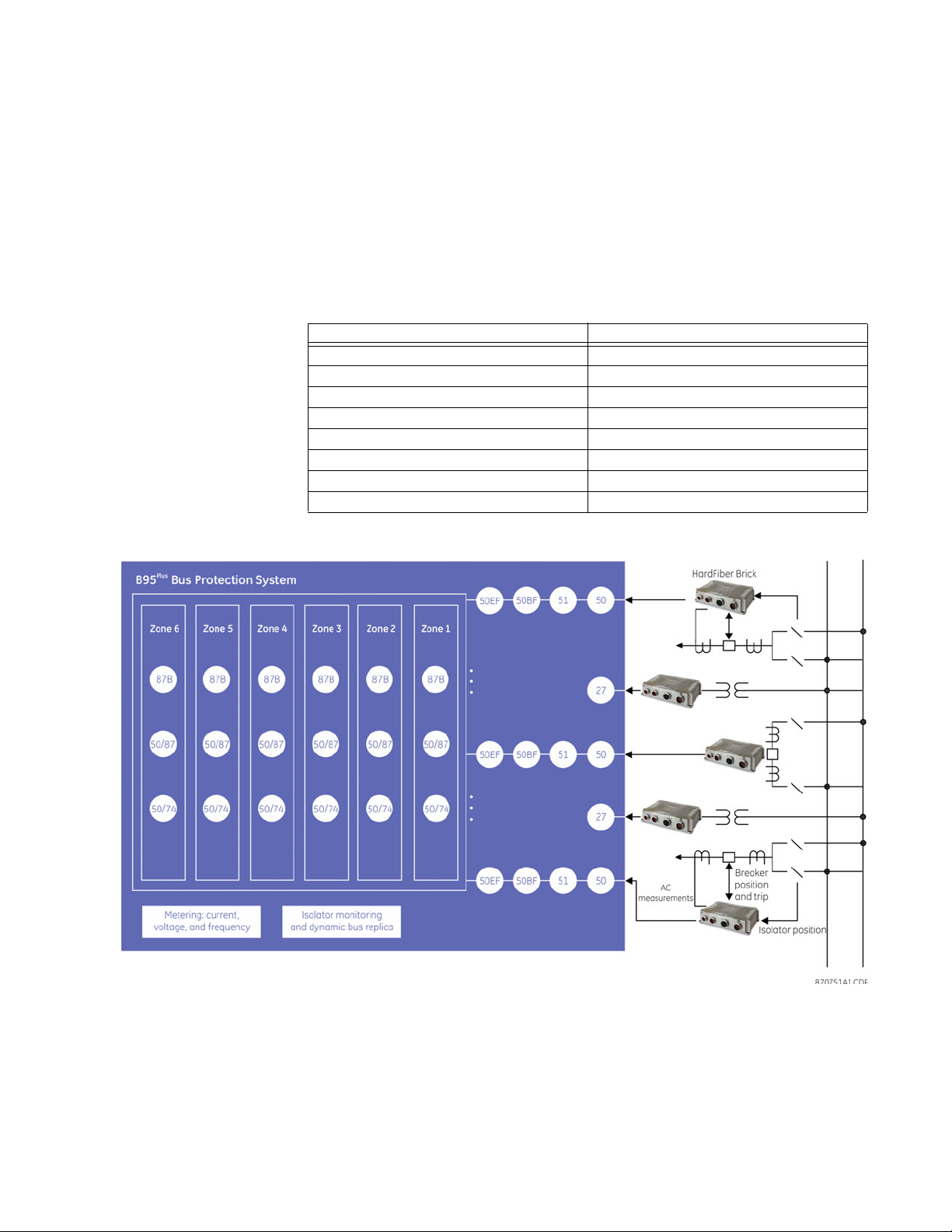
The following single-line diagram illustrates the relay functionality using American
National Standards Institute (ANSI) device numbers.
Table 1: ANSI device numbers and functions
Device Function
87B Percent bus differential
27 Undervoltage
50 Instantaneous overcurrent
50/74 CT trouble
50/87 Unrestrained bus differential
50EF End fault protection
51 Time overcurrent
50BF Breaker failure
Figure 2: ANSI device number schematic
MULTILIN B95
Plus
BUS PROTECTION SYSTEM – INSTRUCTION MANUAL 5
Page 16

DEVICE OVERVIEW CHAPTER 2: PRODUCT DESCRIPTION
Table 2: Other device functions
Function Function
HardFiber Brick interface (8 Bricks per process
card)
Field contact inputs (144 per process card) Event recorder
Field contact outputs (48 per process card) Transient recorder (oscillography)
Current AC banks (12 per process card)
Voltage AC banks (2 per process card)
Dynamic bus replica User-definable mimic, metering, and annunciator
End-fault protection User-programmable self-test
DNP 3.0 or IEC 60870-5-104 communications Virtual inputs (64)
IEC 61850 communications, including GOOSE
and sampled values
Metering: current, voltage, tracking frequency FlexLogic equations (512 lines plus 512 lines per
Modbus communications Non-volatile latches (16 plus 16 per process card)
Modbus user map Setting groups (2)
Differential zone expansion/contraction
Time synchronization via SNTP or IRIG-B
displays
Virtual outputs (96 plus 96 per process card)
process card of protection speed code)
Advanced functionality allows the user to access comprehensive information without
having to navigate through conventional displays and keypads. Information displays on
two graphical display panels on the front panel. One serves as a digital annunciator and
the other, called the HMI, displays mimic diagrams, phasor plots, and other information.
The configurable, color LCD annunciator on the front panel eliminates the need for LEDs
and separate annunciator devices. Any contact input, remote input, or internally
generated logic operand can be assigned to each indicator, as well as any analog
operand. Up to 288 indicators can be assigned. The display can be configured for 12, 24, or
48 indicators per page. A separate self-test message page on the annunciator panel
displays error messages about device health.
The HMI panel provides easy access and visualization of device information, ranging from
the graphical and numeric display of bus source current phasors, voltage source phasors,
differential and restraint phasors, and tracking frequency, as well as a display of sequence
of events and a transient records list. The HMI can display a mimic diagram that provides
the status of each bus source’s breaker and isolators. Many bay configurations can be
realized through the setting of the device.
FlexLogic equations
FlexLogic refers to executable code developed by GE or you for use with the device. You
can create or edit FlexLogic
subsequently view automatically generated logic diagrams.
6 MULTILIN B95
equations in order to customize the relay’s behavior. You can
Plus
BUS PROTECTION SYSTEM – INSTRUCTION MANUAL
Page 17
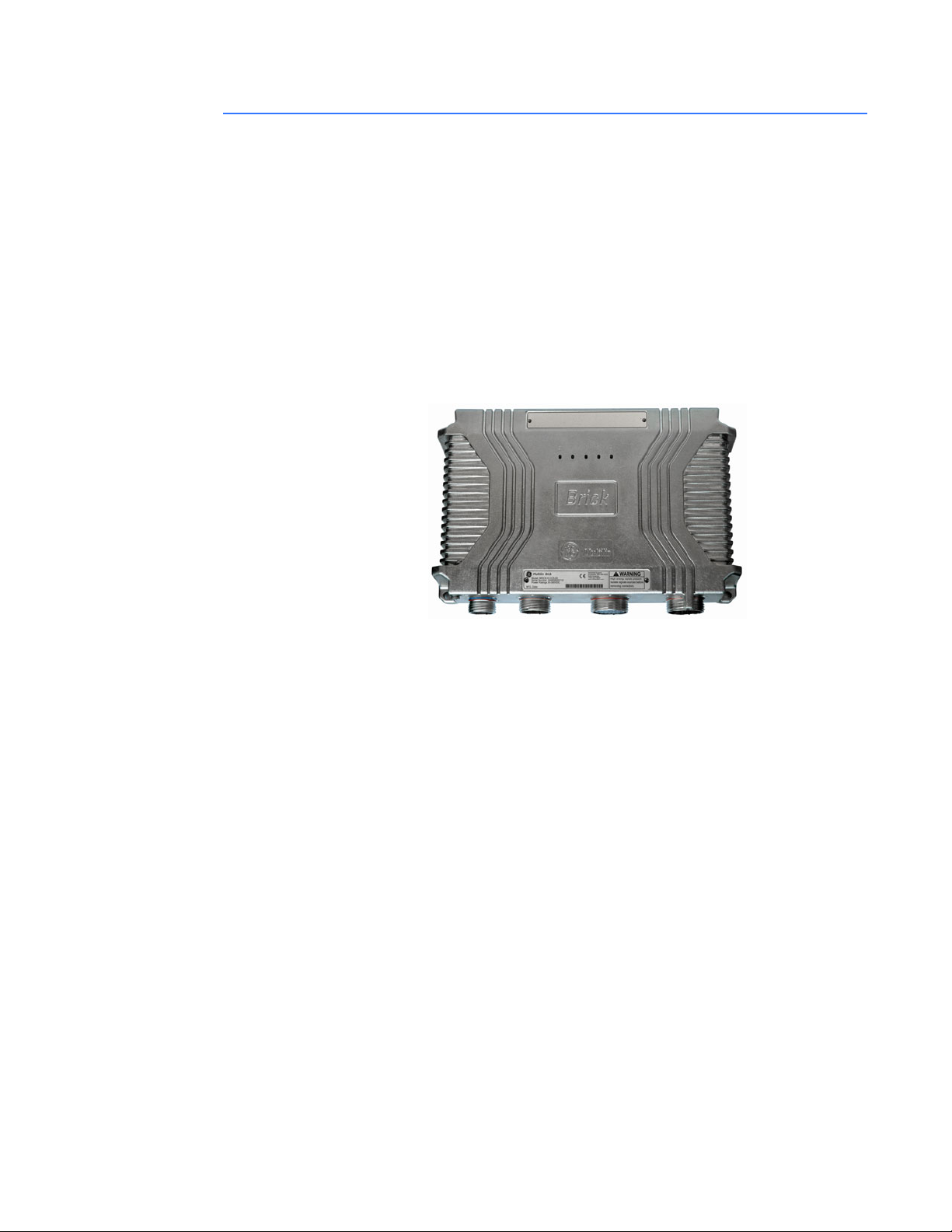
CHAPTER 2: PRODUCT DESCRIPTION HARDFIBER OVERVIEW
HardFiber overview
The GE HardFiber Process Bus System allows copper wiring to be replaced in substation
switchyards with optical fiber. The system includes all physical components required for its
installation: relays; factory pre-terminated fiber cables; fiber crossconnect panels; factory
connectorized copper cables; and switchyard I/O interface devices known as Bricks. The
Bricks implement the concept of an IEC 61850 merging unit, expanded to optically connect
relays with all types of input and output signals in the switchyard, not just instrument
transformers. The relays are the proven GE Multilin Universal Relay (UR) series devices with
a decade-long field record, and they incorporate all major applications from a simple
feeder relay to a sophisticated generator protection package. With the release of the
Plus
, the HardFiber system can also be used for the protection of large and dynamic
B95
buses.
Figure 3: GE HardFiber Brick top view
The HardFiber system replaces copper wiring between power apparatus in the switchyard
and protection and control devices in the control house with off-the-shelf components that
use standard physical and logical interfaces. As such, it shortens deployment time, reduces
labour requirements, facilitates work transfer, improves quality, simplifies procurement,
and improves safety.
MULTILIN B95
Plus
BUS PROTECTION SYSTEM – INSTRUCTION MANUAL 7
Page 18
ORDER CODES CHAPTER 2: PRODUCT DESCRIPTION
NOTE
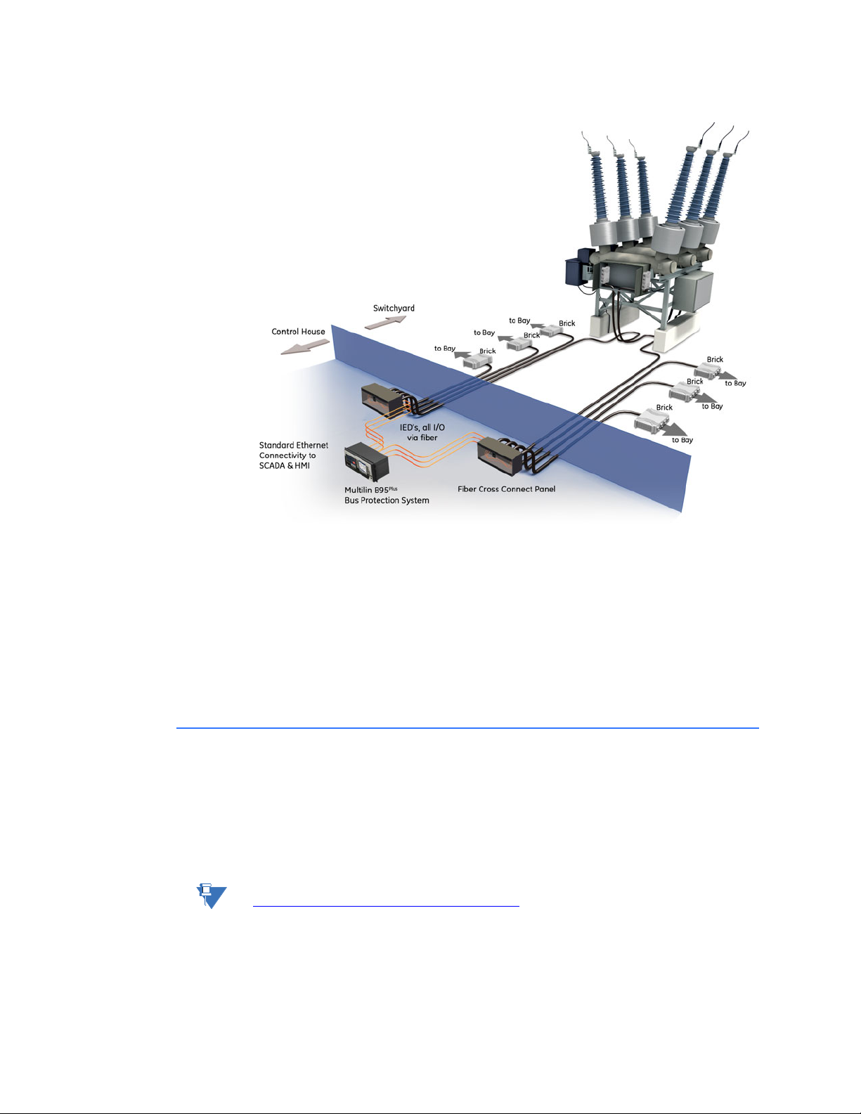
Figure 4: B95
Plus
in control house and HardFiber Bricks in switchyard
Bricks, cables, and crossconnect panels can simultaneously connect to the B95
and UR-series relays. For example, a Brick located in a feeder bay can be used by a D60
Line Distance Protection System protecting the feeder and a B95
The B95
manual refer to HardFiber
Details of the HardFiber Bricks, cables, crossconnect panels, and protocols are contained in
the HardFiber
HardFiber
Plus
is designed to work with GE HardFiber Bricks. Any references to Bricks in this
Process Bus System Reference Manual. Chapters 5 and 6 of the
manual do not apply to the B95
Bricks.
Plus
because the B95
Plus
protecting the bus.
Plus
has its own process
Plus
relays
card, settings, actual values, and self-test errors.
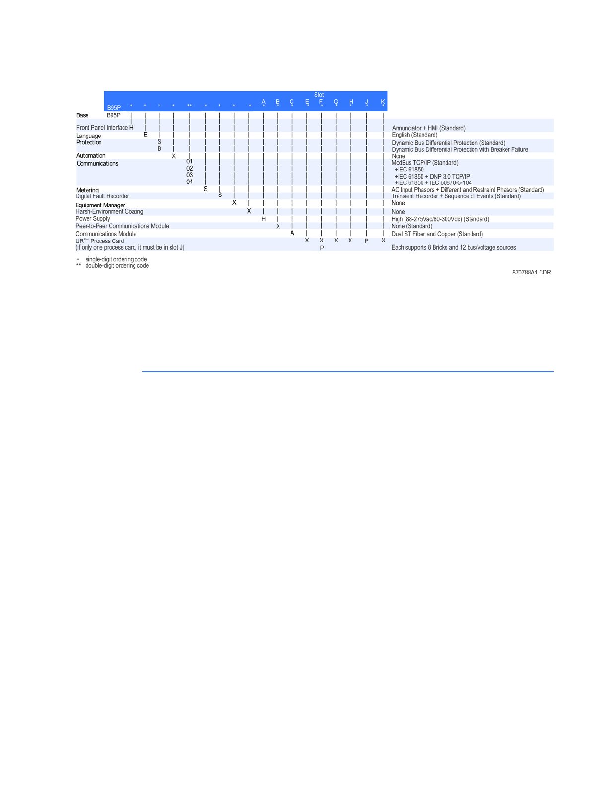
Order codes
The B95
cards. For the B95
The information required to completely specify the system is provided in the following
table. Reading across the order code table, an example of an ordering code is
B95P-HE-BX03SSX-XHXAXPXXPX.
NOTE:
Order codes are subject to change without notice. See the GE Multilin ordering page at
http://www.GEindustrial.com/multilin/order.htm
For communications, the DNP option or the IEC 60870-5-104 option is ordered, not both.
Plus
is a 19-inch horizontal rack-mount unit that consists of required and optional
Plus
, only process card F is optional.
for the latest B95
Plus
options.
8 MULTILIN B95
Plus
BUS PROTECTION SYSTEM – INSTRUCTION MANUAL
Page 19
CHAPTER 2: PRODUCT DESCRIPTION SPECIFICATIONS
Figure 5: Order codes
After the unit is set up, the order code is viewable in the EnerVista software.
To view the order code:
1. In the Online Window area of the EnerVista software, navigate to Actual Values >
Product Information > Model Information. Or view the code on the Product
Information page on the front panel annunciator display.
Specifications
This section outlines specifications, which are subject to change without notice.
Remote resources specifications
REMOTE RESOURCE SPECIFICATIONS
Number of field units (bricks): .......................8 per process card
Number of field contact inputs: ...................18 for each brick
Number of field contact outputs:................6 for each brick
Number of field latching outputs:...............1 for each brick
Number of shared inputs:...............................16 per process card
Number of shared outputs:............................16 per process card
MULTILIN B95
Plus
BUS PROTECTION SYSTEM – INSTRUCTION MANUAL 9
Page 20

SPECIFICATIONS CHAPTER 2: PRODUCT DESCRIPTION
Protection specifications
BUS DIFFERENTIAL PROTECTION
Comparator algorithm:....................................low impedance differential with through current restraint,
direction and CT saturation supervision (same as B90)
Number of differential zones: ....................... six 3-phase zones
Maximum number of currents:.................... total dynamic number of bus source to zone connections
closed at any one moment in time up to 120
CT ratio compensation range:......................32:1
Supervision:........................................................... 2 user-programmable conditions per zone
Pickup level:........................................................... 0.050 to 2.000 pu on bus base in steps of 0.001 pu
Low slope: ..............................................................15 to 100% in steps of 1%
High slope: ............................................................. 50 to 100% in steps of 1%
Low breakpoint:................................................... 1.00 to 30.00 pu on bus base in steps of 0.01 pu
High breakpoint:..................................................1.00 to 30.00 pu on bus base in steps of 0.01 pu
Dropout level: ....................................................... <98% of pickup
Level accuracy:....................................................
0.1 to 2.0 × bus base:.......................................±0.5% of reading or ±1% of bus base (whichever is greater)
>2.0 × bus base: ................................................. ±1.5% of reading
Operating time:.................................................... <1 power system cycle
High set (unbiased) level: ................................2.00 to 99.99 pu in steps of 0.01 pu
High set (unbiased) operate time:............... <1 power system cycle
CT TROUBLE MONITORING
Number of CT trouble detectors:................. 1 per bus differential zone, that is, 6
Responding to:..................................................... differential current
Pickup level:........................................................... 0.020 to 2.000 pu in steps of 0.001 pu
CT trouble operate delay: ...............................1.0 to 60.0 s in steps of 0.1 s
Supervision trouble delay:.............................. 0.00 to 5.00 cycles in steps of 0.25
BUS REPLICA
Features:.................................................................Dynamic bus source current assignment to each zone.
Dynamic zone trip assignment to each bus source. Dynamic
blocking of zones on CT bypassed. 3 user-programmable
auxiliary zone trip inputs. 3 user-programmable bus source
trip inputs. Dynamic zone expansion/reduction.
BUS SOURCES
Number of bus sources: .................................. 12 per process card included in the order code
Current inputs: .....................................................3-phase currents
CT rated primary:................................................1 to 65000 A
CT rated secondary: .......................................... 1 or 5 A
Nominal frequency:........................................... 50 or 60 Hz
10 MULTILIN B95
Plus
BUS PROTECTION SYSTEM – INSTRUCTION MANUAL
Page 21

CHAPTER 2: PRODUCT DESCRIPTION SPECIFICATIONS
BREAKER FAILURE PROTECTION
Number of BF protections: .............................1 per bus source
Mode:........................................................................3-pole initiate only
Current supervision: ..........................................phase current
Current supervision pickup: ...........................0.01 to 30.00 pu on CT base in steps of 0.01 pu
Current supervision dropout: ........................<98% of pickup
Current supervision accuracy:......................
0.1 to 2.0 × CT rating: .......................................±0.75% of reading or ±2% of CT base (whichever is greater)
above 2 × CT rating:..........................................±2.5% of reading
Current supervision reset time:....................< 0.5 cycles
Coordination delay timers:.............................0 to 60 s in steps of 1 ms
Delay accuracy:...................................................±3% or ±4 ms, whichever is greater
Breaker position inputs:...................................advanced and final position contact inputs, each optionally
dual-redundant
Stages: .....................................................................current + advanced breaker position status + time
current + time
final breaker position + time
opening resistor protection
INSTANTANEOUS PHASE OVERCURRENT
Number of IOC protections: ...........................1 per bus source
Comparators:........................................................3 phase, sensing fundamental frequency current
Pickup level:...........................................................0.00 to 30.00 pu on CT base in steps of 0.01
Dropout level:........................................................<98% of pickup
Level accuracy: ....................................................
0.1 to 2.0 × CT:.....................................................0.5% of reading or 1% of CT base (whichever is greater)
above 2.0 × CT:....................................................1.5% of reading
Pickup delay: .........................................................0 to 60 s in steps of 1ms
Reset delay: ...........................................................0 to 60 s in steps of 1ms
Delay accuracy:...................................................±3% or ±4 ms (whichever is greater)
Operate time:........................................................<1 power system cycle at 3 x pickup
INVERSE TIME PHASE OVERCURRENT
Number of TOC protections:..........................1 per bus source
Comparators:........................................................3 phase, sensing fundamental frequency current
Pickup level:...........................................................0.01 to 30.00 pu on CT base in steps of 0.01 pu
Dropout level:........................................................<98% of pickup
Level accuracy: ....................................................
0.1 to 2.0 × CT:.....................................................0.5% of reading or 1% of CT base (whichever is greater)
above 2.0 × CT:....................................................1.5% of reading
Curve shapes:.......................................................IEEE Moderately/Very/Extremely Inverse; IEC (and BS) A/B/C
and Short Inverse; GE IAC Inverse, Short/Very/ Extremely
Inverse; I2t; Definite T ime (0.01 s base curve)
TD multiplier: .........................................................0.00 to 600.00 in steps of 0.01
Reset type:..............................................................instantaneous or timed (per IEEE)
Timing accuracy: ................................................±3% or ±40 ms (whichever is greater)
END FAULT PROTECTION
Number of EFPs:..................................................1 per bus source
IOC pickup level: ..................................................0.01 to 30.00 pu in steps of 0.01 pu
IOC dropout level: ...............................................<98% of pickup
Level accuracy: ....................................................
at 0.1 to 2.0 × CT: ...............................................0.5% of reading or 1% of nominal (whichever is greater)
above 2.0 × CT:....................................................1.5% of reading
CB open delay timer:.........................................0.10 to 60 s in steps of 1 ms
End fault dropout timer:...................................0 to 60 s in steps of 1 ms
Time accuracy: ....................................................±3% or ±8 ms (whichever is greater)
MULTILIN B95
Plus
BUS PROTECTION SYSTEM – INSTRUCTION MANUAL 11
Page 22

SPECIFICATIONS CHAPTER 2: PRODUCT DESCRIPTION
VOLTAGE SOURCES
Number of voltage sources:.......................... 2 per process card included in the order code
Voltage inputs:..................................................... 3-phase voltages, wye or delta
VT ratio: ...................................................................1.00 to 24000.00
VT rated secondary: ..........................................25.0 to 240.0 V
Nominal frequency:........................................... 50 or 60 Hz
UNDERVOLTAGE PROTECTION
Number of UV protections: ............................2 per process card
Comparators: .......................................................3 phase-to-phase and 3 phase-to-ground
Pickup level:........................................................... 0.50 to 1.50 pu in steps of 0.01
Dropout level: ....................................................... >102% of pickup
Level accuracy:....................................................±0.5% of reading from 10 to 208 V
Operate time:........................................................ <1 power system cycle at 0.5 x pickup
ISOLATORS
Number of isolators:.......................................... 48 per process card
Isolator status inputs:....................................... form “a” and form “b” contact inputs, each optionally dual-
redundant
Configurable failsafe modes:........................ open, closed, last valid state
Monitoring:............................................................. alarm on inconsistent inputs persisting longer than a user
set time
FLEXLOGIC DESIGN
Programming language:................................. Reverse Polish Notation with graphical visualization
Inputs: ...................................................................... Any logical variable, contact , or virtual input
Number of timers: .............................................. 32 per process card plus 32 on main card
Timer pickup delay: ........................................... 0 to 1000 hrs in steps of 1 ms
Timer dropout delay: ........................................ 0 to 1000 hrs in steps of 1 ms
Timer accuracy: .................................................. ± the sum of 1/8 power system cycle and 1% of the timer
setting
Virtual outputs: .................................................... 96 per process card plus 96 on main card
Non-volatile latch latches: ............................. 16 per process card plus 16 on main card
Non-volatile latch modes: .............................. Set-dominant or reset-dominant
Lines of code:........................................................ 512 per process card plus 512 on main card
Supported operations: ..................................... NOT, XOR, OR (2 to 16 inputs), AND (2 to 16 inputs), NOR (2 to
16 inputs), NAND (2 to 16 inputs), latch (reset-dominant),
edge detectors, timers
Execution speed:................................................. recalculated at 8 times per power system cycle
Card-to-card operand delay:........................ up to 1/8 power system cycle
SETTINGS GROUPS
Number of settings groups:...........................2
Grouped settings:............................................... threshold type settings for bus source, voltage source, and
bus differential
Communications specifications
MODBUS USER MAP
Number: .................................................................. up to 256 Modbus addresses
Programmability: ................................................ any setting or actual value in decimal
REMOTE INPUTS (IEC 61850 GSSE/GOOSE)
Input points: ..........................................................64
Remote devices:.................................................. 32
Default states on loss of
communications:........................................... On, Off, Latest/Off, Latest/On
Remote double-point status inputs:.......... 16
12 MULTILIN B95
Plus
BUS PROTECTION SYSTEM – INSTRUCTION MANUAL
Page 23

CHAPTER 2: PRODUCT DESCRIPTION SPECIFICATIONS
REMOTE OUTPUTS (IEC 61850 GSSE/GOOSE)
GSSE:.........................................................................32 DNA + 32 UserSt
GOOSE:.....................................................................128 status
IEC 61850 LOGICAL NODES
LLNO: ........................................................................1 logical node zero
LPHD: ........................................................................1 physical device information
GGIO:.........................................................................GGIO1, general status output
PDIF: ..........................................................................6 differential zones
PIOC:..........................................................................1 per bus source instantaneous overcurrent
PTOC:.........................................................................1 per bus source timed overcurrent
PTUV:.........................................................................1 per undervoltage
RBRF:.........................................................................1 per bus source breaker failure
PTRC:.........................................................................1 per bus source
MMXU: ......................................................................1 per bus source phase current bank
MMXU: ......................................................................1 per voltage source
IEC 61850 REPORTS
Unbuffered control blocks:.............................3 for GGIO1
3 for each PDIF
3 for each MMXU
Buffered control blocks:...................................2 for GGIO1
1 for each PDIF
1 for each MMXU
Digital fault recorder specifications
TRANSIENT RECORDER
Storage capacity:................................................five records with all channels recorded, at 128 samples per
cycle, spanning 1 second with no retriggers
Number of records:............................................up to 50
Sampling rate: ......................................................8, 16, 32, 64, or 128 samples per power cycle
AC waveform channels:...................................all enabled bus sources and voltage sources
Analog channels: ................................................magnitudes and angles of all AC waveforms recorded plus
all enabled zone differential and zone restraint phase
current magnitudes and angles
Digital channels:..................................................128 user-configurable channels on the main card and 128
user-configurable channels on each process card
Configurable digital data: ...............................any FlexLogic operand
Storage modes:....................................................automatic overwrite, protected
Triggering modes:...............................................time window from rising edge of trigger, continuous
recording as long as trigger is active
Pre-trigger window:...........................................0 to 100% of the basic record length
Data storage:........................................................non-volatile memory
EVENT RECORDER
Storage capacity:................................................4,096 events plus 4,096 events on each process card
Time tag:.................................................................to 1 µs
Triggers:...................................................................most FlexLogic operand activations
MULTILIN B95
Plus
BUS PROTECTION SYSTEM – INSTRUCTION MANUAL 13
Page 24

SPECIFICATIONS CHAPTER 2: PRODUCT DESCRIPTION
Front panel interface
ANNUNCIATOR MAIN DISPLAY
Annunciator pages: ...........................................
Indicators: ..............................................................288
Indicators per page:......................................... 12 to 48
Pages: .....................................................................up to 24
Sequence: .............................................................manual reset, locking
Off indication:...................................................... alarm inactive and reset
Flashing indication: ..........................................alarm active and not acknowledged, alarm inactive and not
acknowledged
On indication: ...................................................... alarm active and acknowledged, alarm inactive and not
reset
Priority: ...................................................................by active window and page number
Data storage: ......................................................non-volatile memory
Other annunciator displays:..........................
Product information page:............................ displays order code, serial number, relay ID, configuration
name and date, and firmware version and date
Communication status page: ......................displays remaining connections for MMS, Modbus, DNP, PMU,
IEC. Also displays Modbus slave addresses and TCP/IP port.
Also displays for Ethernet ports their MAC address, IP
addresses, subnet mask, and gateway.
Self-test summary page: ...............................displays all active or unacknowledged B95
related self-test messages in a sequence of events format
HMI DISPLAY
Mimic diagram:.................................................... mimic diagrams display bus source breaker and isolator
status
Phasors: .................................................................. digital and phasor diagram display of present voltage source
phase voltages, bus source phase currents, zone differential
currents, and zone restraint currents, both magnitudes and
angles
Sequence of events:..........................................displays the stored events record
Transient records:............................................... list of stored transient records
MULTI-LANGUAGE SUPPORT
Languages:............................................................English
Plus
device -
Security specifications
SECURITY SPECIFICATIONS
Features:.................................................................Two access levels (Command and Setting), with separate
remote and local passwords for each level. Dictionary attack
deterrence. Programmable authorization control.
Hardware specifications
PROCESS I/O
Number of process bus ports:...................... 8 per process card
Port type: ................................................................100Base-BX-D, in SFP package with LC 50/125 µm multi-
mode connector
Transceiver diagnostics: .................................per SFF-8472
Brick synch frame jitter:................................... ±1 µs
14 MULTILIN B95
Plus
BUS PROTECTION SYSTEM – INSTRUCTION MANUAL
Page 25

CHAPTER 2: PRODUCT DESCRIPTION SPECIFICATIONS
NOTE
ETHERNET PORTS
Standard: ................................................................2 ports on the communications card supporting SNTP, TFTP,
Modbus TCP, DNP 3.0, IEC 60870-5-104, IEC 61850, or
EnerVista software. 1 port on main processor card
supporting EnerVista software.
Media types: ..........................................................100Base-FX or 10/100Base-TX
100Base-FX type:................................................
Power budget:.....................................................10dB
Maximum input power:...................................–14 dBm
Receiver sensitivity:...........................................–30 dBm
Typical distance:.................................................2.0 km
10/100Base-TX type:.........................................RJ45 connector
SNTP clock synchronization:..........................<10 ms typical
USB FRONT PORT
Standard: ................................................................type B USB connector for EnerVista software
IRIG-B INPUT
Amplitude modulation:.....................................1 to 10 V pk-pk
DC shift: ...................................................................TTL
Input impedance:................................................50 kΩ
Isolation:..................................................................2 kV
NOTE:
An internal clock free runs when neither the IRIG-B signal nor SNTP is present.
CRITICAL FAILURE RELAY
Type:..........................................................................Form-C, normally energized
Make and carry for 0.2 s:.................................10 A as per ANSI C37.94
Carry continuous: ...............................................6 A
Break at L/R of 40 ms:.......................................0.25 A DC at 125 V DC; 0.125 A DC at 250 V DC
POWER SUPPLY
Nominal DC voltage:..........................................125 to 250 V
Minimum DC voltage:........................................80 V
Maximum DC voltage: ......................................300 V
Nominal AC voltage:..........................................100 to 240 V at 50/60 Hz
Minimum AC voltage:........................................80 V at 48 to 62 Hz
Maximum AC voltage:.......................................275 V at 48 to 62 Hz
Voltage withstand: .............................................2 × highest nominal voltage for 10 ms
Voltage loss ride-through:..............................200 ms duration at nominal input voltage
Power consumption: .........................................65 VA maximum
Control power wiring:........................................14 AWG or larger
Control power protection:...............................Has internal non-user replaceable 4 Amp "slo blo" fuse.
Recommend external upstream disconnect on both sides.
Recommend external overcurrent protection of 5 to 10
Amps.
Control power terminal connection:..........Use suitable ring terminal, torque terminal to 9 in lb (1 N-m)
Grounding connection: ....................................10 AWG or larger wire or braid, independent and direct-to-
cubicle ground bus
MULTILIN B95
Plus
BUS PROTECTION SYSTEM – INSTRUCTION MANUAL 15
Page 26

SPECIFICATIONS CHAPTER 2: PRODUCT DESCRIPTION
PROCESS CARD OPTICAL
Number of transceivers:.................................. 8
Transceiver type: ................................................transmit 1550 nm, receive 1310 nm, 100 Mbps, bidirectional
single-fiber 50/125 µm multimode module (complies with
IEEE 802.3 standard 100Base-BX-D)
Optical transmit power:................................... –14 to –8 dBm
Maximum optical input power: .................... –8 dBm
Optical receiver sensitivity: ............................ –30 dBm
Termination:.......................................................... LC fiber connector
Laser class:............................................................ Class 1. Class 1 devices are considered safe to the unaided
eye. Do not view directly with optical instruments.
Test specifications
Test Reference standard Test level
Dielectric voltage withstand EN 60255-5 2.3 KV
Impulse voltage withstand 5 KV
Insulation resistance 500 Vdc
Damped oscillatory IEC 61000-4-18 / IEC 60255-22-1 2.5 KV CM, 1 KV DM
Electrostatic discharge EN 61000-4-2 / IEC 60255-22-2 Level 4
RF immunity EN 61000-4-3 / IEC 60255-22-3 Level 3
Fast transient disturbance EN 61000-4-4 / IEC 60255-22-4 Area B
Surge immunity EN 61000-4-5 / IEC 60255-22-5 Level 3
Conducted RF immunity EN 61000-4-6 / IEC 60255-22-6 Level 3
Voltage interruption and ripple DC IEC 60255-11 15% ripple, 200 ms
Radiated and conducted emissions CISPR 11 / CISPR 22 / IEC 60255-25 Class A
Sinusoidal vibration IEC 60255-21-1 Class 1
Shock and bump IEC 60255-21-2 Class 1
Seismic IEC 60255-21-3 Class 2
Power magnetic immunity IEC 61000-4-8 Level 5
Pulse magnetic immunity IEC 61000-4-9 Level 4
Damped magnetic immunity IEC 61000-4-10 Level 4
Voltage dip and interruption IEC 61000-4-11 0, 40, 70, 80% dips, 250/
Voltage ripple IEC 61000-4-17 15% ripple
Ingress protection IEC 60529 IP30Front
Environmental (cold) IEC 60068-2-1 -40°C / 16 hours
Environmental (dry heat) IEC 60068-2-2 85°C / 16 hours
Relative humidity cyclic IEC 60068-2-30 6 day, variant 1
Electrostatic discharge IEEE ANSI C37.90.3 8 KV contact, 15 KV air
Damped oscillatory IEEE ANSI C37.90.1 2.5 KV, 1 MHz
Fast transient disturbance IEEE ANSI C37.90.1 4 KV, 2.5 KHz
RF immunity IEEE ANSI C37.90.2 20 V/m, 80-1 GHz
Safety UL 508 e83849 NKCR
UL C22.2-14 e83849 NKCR7
UL 1053 e83849 NKCR
interrupts
300 cycle interrupts
16 MULTILIN B95
Plus
BUS PROTECTION SYSTEM – INSTRUCTION MANUAL
Page 27

CHAPTER 2: PRODUCT DESCRIPTION SPECIFICATIONS
Environmental specifications
TEMPERATURE
Cold: ..........................................................................IEC 60028-2-1, 16 hours at –40°C
Dry heat:..................................................................IEC 60028-2-2, 16 hours at 85°C
Humidity:.................................................................Up to 95°C non-condensing at 55°C, as per IEC 60068-2-30
variant 1, 6 days
Storage temperature: .......................................-40 to 85°C
Operating temperature:...................................-40 to 60°C
OTHER ENVIRONMENTAL SPECIFICATIONS
Altitude:....................................................................up to 2000 m
Insulation class:...................................................I
Overvoltage category:......................................II
IP rating: ..................................................................IP30
Pollution degree: .................................................II
Approvals and certification
APPROVALS AND CERTIFICATION
Compliance: ..........................................................CE, CSA, UL, ISO
Compliance Applicable council directive According to
CE Low voltage directive EN 60255-27 (normative sections)
EMC directive EN 60255-26 / EN 50263
EN 61000-6-5 (Area G)
C-UL-US --- UL 508
UL 1053
C22.2 No 14
ISO --- ISO 9001:2008
MULTILIN B95
Plus
BUS PROTECTION SYSTEM – INSTRUCTION MANUAL 17
Page 28

SPECIFICATIONS CHAPTER 2: PRODUCT DESCRIPTION
18 MULTILIN B95
Plus
BUS PROTECTION SYSTEM – INSTRUCTION MANUAL
Page 29

GE Energy
Plus
Multilin B95
Bus Protection
System
Chapter 3: Installation
Installation
This section describes the physical and electrical installation of the Multilin B95
Protection System.
Installing the unit in a rack
The B95
be upgraded and repaired by qualified service personnel. The front faceplate is hinged to
allow access to the removable modules.
The case dimensions are shown in the figures, along with cutout details for panel
mounting. When planning the location of your panel cutout, ensure that provision is made
for the faceplate to swing open. Under normal operating conditions, the unit has no special
cooling requirements, but adequate clearance must be provided to the bottom, sides, and
top of the device to allow air to circulate. Do not block the ventilation openings of the
chassis. Do not place other equipment or panels in such a way to obstruct airflow around
the chassis.
The unit is typically installed in the control center.
To install the unit:
1. Mount the unit in a 19-inch rack such that the front faceplate sits semi-flush with the
2. Secure the B95
3. Wire the unit as outlined in the Typical Wiring Diagram section.
Plus
is a 19-inch horizontal rack-mount unit. The modular design allows the relay to
panel or switchgear door, allowing the operator access to the front panel keys and
USB communications port. Leave a 1U (1 rack-unit) space below the chassis for
ventilation and for the front panel to swing open without obstruction. No extra space
is required above the chassis. Clearance is provided by the shape of the mounting
plate. Do not install other equipment or panels in such a way to obstruct this
clearance.
Plus
to the panel using the four screws supplied with the relay.
Plus
Bus
MULTILIN B95
Plus
BUS PROTECTION SYSTEM – INSTRUCTION MANUAL 19
Page 30
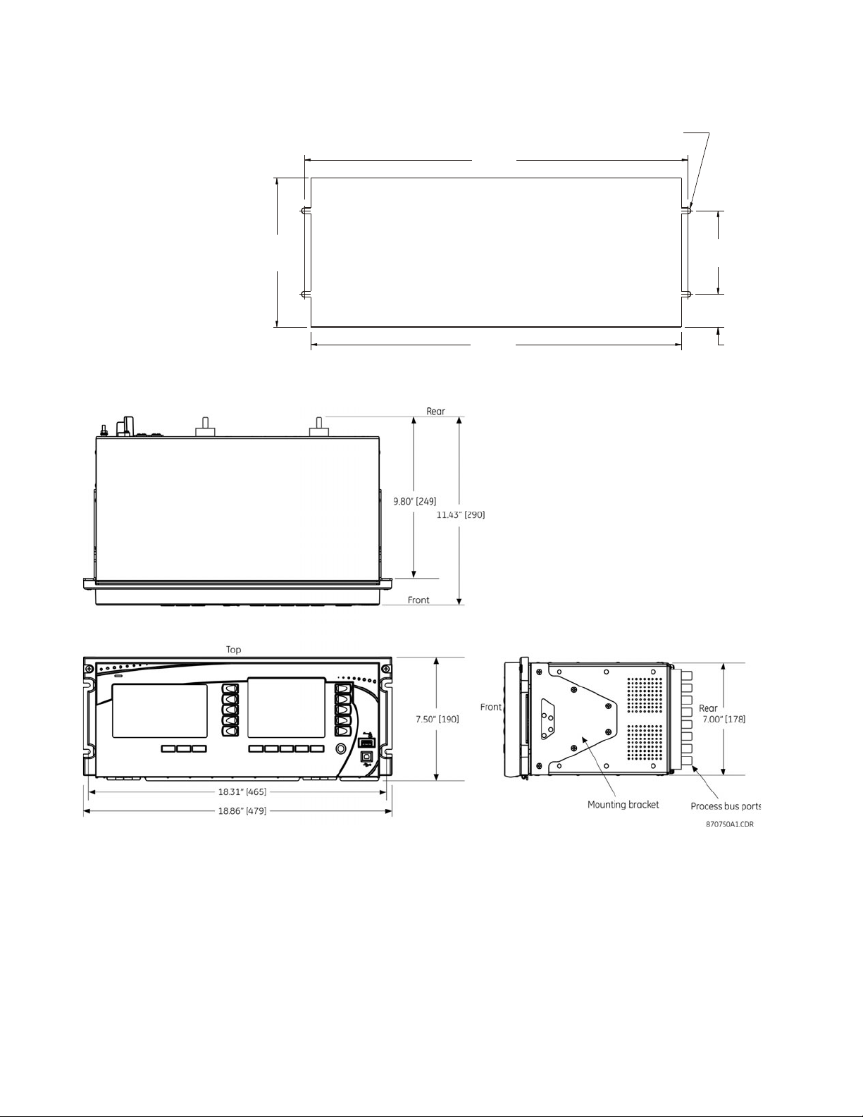
INSTALLING THE UNIT IN A RACK CHAPTER 3: INSTALLATION
$&'5
&87287
îGLDPHWHU
Figure 1: Panel cutout dimensions
Figure 2: Dimensions
20 MULTILIN B95
Plus
BUS PROTECTION SYSTEM – INSTRUCTION MANUAL
Page 31

CHAPTER 3: INSTALLATION REAR TERMINAL AND PORT LAYOUT
Rear terminal and port layout
The back of the B95
Figure 3: Rear terminal view
Plus
chassis is shown in the figure.
Printed circuit cards are housed in slots. The slots are labelled from right to left: A, B, C, D, E,
F, G, H, J, K. Active slots are as follows:
• Slot A — Contains the power supply card, which conditions the AC or DC station
service power such that it is suitable for internal use, and contains the critical failure
relay. Terminals on the power supply card are designated 1 thorough 10 with a slot
letter (slot A) prefix.
• Slot C — Contains the communications card, which handles all station bus type
Ethernet communications for the relay. The Ethernet ports on the communications
card are port 2 on the top and port 3 on the bottom.
• Slot D — Contains the main card, which handles central processing tasks. Ports from
top to bottom are IRIG-B and Ethernet port 1.
• Slot F — Optional — Same as slot J, if present
• Slot J — Contains a process card to connect to up to eight HardFiber Bricks and
implement protection and control elements for 12 bus sources and two voltage
sources. The port number assignments are two characters, assigned in order by card
slot position (slot F or J) and the row number (1 through 8, top to bottom).
Other slots are empty.
MULTILIN B95
Plus
BUS PROTECTION SYSTEM – INSTRUCTION MANUAL 21
Page 32

TYPICAL WIRING DIAGRAM CHAPTER 3: INSTALLATION
Typical wiring diagram
IMPORTANT:
This section outlines the electrical installation of the B95
connections, see the HardFiber
manual.
Plus
. For Brick and fiber cable
The unit can be connected to AC or DC power. Use of DC power is typical in the field.
Ensure that power is not live when connecting the wires to the unit, else injury or death
can result.
The following wiring diagram provides an example of how to wire the device. Actual wiring
varies according to application.
Figure 4: Typical wiring diagram
After wiring the unit, to continue with installation skip ahead to Installing the EnerVista
software section.
22 MULTILIN B95
Plus
BUS PROTECTION SYSTEM – INSTRUCTION MANUAL
Page 33

CHAPTER 3: INSTALLATION DIELECTRIC STRENGTH
Dielectric strength
Dielectric strength is the maximum electric strength that can be sustained without
breakdown. It is measured in volts.
The dielectric strength of the B95
Table 1: Dielectric strength for the B95
Function Terminals Dielectric strength
Power supply module high (+), low (+), (–) chassis 2,000 V AC for 1 minute
Power supply module relay terminals chassis 2,000 V AC for 1 minute
Main CPU RJ45 port chassis 1,500 V AC for 1 minute
Main CPU IRIG-B port chassis 2,000 V AC for 1 minute
Front panel USB port chassis 2,000 V AC for 1 minute
Communications module RJ45 ports chassis 1,500 V AC for 1 minute
Filter networks and transient protection clamps are used in the hardware to prevent
damage caused by high peak voltage transients, radio frequency interference (RFI), and
electromagnetic interference (EMI).
NOTE:
The protective components can be damaged by application of the test voltage for a period
longer than the specified minute.
Plus
hardware is outlined in the table.
Plus
from to
Power supply card (slot A)
The power supply card in slot A provides power to the unit. It can be connected to any of
the following standard power sources:
• DC power — 110, 125, 220, or 250 V DC
• AC power — 115 or 230 V AC
Figure 5: Slot A on back of unit
The setup is shown schematically in the figure.
MULTILIN B95
Plus
BUS PROTECTION SYSTEM – INSTRUCTION MANUAL 23
Page 34

POWER SUPPLY CARD (SLOT A) CHAPTER 3: INSTALLATION
Figure 6: Control power connection
NOTE:
Control power supplied to the unit must be connected to the matching power supply
terminal of the unit. If the voltage is applied to the wrong terminals, damage can occur.
NOTE:
The B95
Plus
, like almost all electronic relays, contains electrolytic capacitors. These
capacitors are well-known to be subject to deterioration over time if voltage is not applied
periodically. Avoid deterioration by powering up the unit once a year.
The power supply card provides a critical failure relay, with form-C contacts that are
energized once control power is applied and the relay successfully boots up with no critical
self-test failures. If ongoing self-tests detect a critical failure or power is lost, then the
critical failure relay de-energizes. This feature gives external indication when the relay has
failed.
Extensive filtering and transient protection has been incorporated into the unit to ensure
reliable operation in harsh industrial environments. Transient energy is removed from the
relay and conducted to ground via the ground terminal. This terminal must be connected
to the cubicle ground bus using a 10 AWG or larger stranded wire or ground braid. Do not
daisy-chain grounds with other relays or devices. Each is to have an independent and
direct connection to the ground bus.
The control power to the power supply card is protected by a non-replaceable 4 Amp sloblo fuse. 14 AWG or larger stranded wire is recommended for control power connection. A
ring terminal is recommended to ensure integrity of the connection. The rated torque for
the terminal screw is 9 in lb (1 N m). External downstream disconnects and external
overcurrent protection of 5 to 10 Amps are recommended for both control power inputs.
24 MULTILIN B95
Plus
BUS PROTECTION SYSTEM – INSTRUCTION MANUAL
Page 35

CHAPTER 3: INSTALLATION COMMUNICATIONS CARD (SLOT C)
NOTE
Communications card (slot C)
The communications card has two Ethernet ports designated as ports 2 and 3. They allow
the B95
computers running the EnerVista software. The ports are independent of each other. They
run all protocols supported by the relay.
Each port supports IEEE 802.3 100Base-FX on an ST fiber connector and IEEE 802.3
100Base-TX on an RJ45 copper connector. Only one of these two Ethernet media types can
be used on a given port at a given time; the relay automatically recognizes and uses the
particular media connected on each port .
The optical fiber sizes supported are 50/125 µm and 62.5/125 µm; the wavelength is
1310 nm. IEEE 802.3 100Base-FX light levels are used, and as such can be connected
directly to another 100Base-FX device without an attenuator. When splicing optical fibers,
the diameter and numerical aperture of each fiber must be the same. In order to engage
or disengage the ST connector, only a quarter turn of the coupling is required.
NOTE:
Ensure that the dust covers are installed when the fiber is not in use. Dirty or scratched
connectors can lead to high losses on a fiber link.
The figure shows slots D and C on the rear of the unit.
Figure 7: Slots D and C on rear of unit
Plus
to communicate at high speed (100 Mbps) with gateways, other relays, and
MULTILIN B95
Main processor card (slot D)
The main processor module contains ports for Ethernet communications and IRIG-B
connection.
Ethernet port
Ethernet ports allow the B95
and computers running the EnerVista software. The main processor card has one Ethernet
port designated as port 1 to distinguish it from ports 2 and 3 on the communications card.
Plus
BUS PROTECTION SYSTEM – INSTRUCTION MANUAL 25
Plus
to communicate at high speed (100 Mbps) with gateways
Page 36

MAIN PROCESSOR CARD (SLOT D) CHAPTER 3: INSTALLATION
NOTE
Port 1 is typically used as the main Ethernet connection between the unit and the network.
It is intended for engineering services, such as setting management and historical record
retrieval, and so runs TFTP, FTP, HTTP, SNTP, and Modbus/TCP/IP. This includes the ability to
interface with the EnerVista B95
Plus
Setup software for settings management, monitoring,
and recovering historical records.
The port supports IEEE802.3 100Base-FX on an ST fiber connector and IEEE 802.3
100Base-TX on an RJ45 copper connector. Only one of these two Ethernet media types can
be used on the port at a given time; the relay automatically recognizes and uses the
particular media connected.
The optical fiber sizes supported are 50/125 µm and 62.5/125 µm; the wavelength is
1310 nm. IEEE 802.3 100Base-FX light levels are used, and as such can be connected
directly to another 100Base-FX device without an attenuator. When splicing optical fibers,
the diameter and numerical aperture of each fiber must be the same. In order to engage
or disengage the ST connector, only a quarter turn of the coupling is required.
NOTE:
Ensure that the dust covers are installed when the fiber is not in use. Dirty or scratched
connectors can lead to high losses on a fiber link.
IRIG-B port
IRIG-B is a standard time code format that allows stamping of events to be synchronized
among connected devices within one millisecond. The IRIG time code formats are serial,
pulse width-modulated codes that can be either DC level shifted or amplitude modulated
(AM).
Third-party equipment is available for generating the IRIG-B signal. This equipment can use
a global positioning system (GPS) satellite system to obtain the time reference so that
devices at different locations can also be synchronized.
Figure 8: IRIG-B connection
Other options are to use simple network time protocol (SNTP) and the internal clock.
For additional information, refer to:
Real time clock and IRIG-B on page 97
26 MULTILIN B95
Plus
BUS PROTECTION SYSTEM – INSTRUCTION MANUAL
Page 37

CHAPTER 3: INSTALLATION PROCESS CARDS (SLOT J AND OPTIONALLY SLOT F)
NOTE
Process cards (slot J and optionally slot F)
The unit comes with one or two process cards, these being slots J and F. They are used to
connect to the GE HardFiber
Each process card contains eight optical fiber Ethernet ports, each of which can interface
with a Brick, through which the B95
waveform information, contact input information (such as isolator and breaker status), and
through which the B95
Plus
In B95
units with a single process card, the card is installed in slot J. In relays with two
Bricks.
Plus
acquires power system voltage and current
Plus
issues breaker trip commands.
process cards, the cards are installed in slots F and J. Process card ports are designated
with the card’s slot number followed by the port number on that card. The port numbers
run from 1 through 8, top to bottom. For example, the top port on the process card in slot J
is designated “J1,” and the bottom port on the process card in slot F is designated “F8.”
All process bus ports comply with IEC 802.3 100Base-BX, but with LC connectors and
supporting multimode fiber. More detail on the fiber and the communications profile of IEC
61850 are contained in the HardFiber
NOTE:
Ensure that the dust covers are installed when the fiber is not in use. Dirty or scratched
Process Bus System Reference Manual.
connectors can lead to high losses on a fiber link.
Figure 9: Process card J
MULTILIN B95
Plus
BUS PROTECTION SYSTEM – INSTRUCTION MANUAL 27
Page 38

PROCESS CARDS (SLOT J AND OPTIONALLY SLOT F) CHAPTER 3: INSTALLATION
28 MULTILIN B95
Plus
BUS PROTECTION SYSTEM – INSTRUCTION MANUAL
Page 39

GE Energy
Plus
Multilin B95
Bus Protection
System
Chapter 4: EnerVista software
EnerVista software
The GE EnerVista software supplied with the Multilin B95
provides tools to configure, monitor, maintain, and integrate information
System
generated.
Introduction
The EnerVista B95
configure, monitor, and maintain operation of the B95
or over local or wide area networks.
The software can be used in offline mode (not communicating with a B95
mode (communicating with a B95
or configured for eventual downloading to the B95
Plus
B95
addition, the relay’s actual values can be monitored and historical records recovered and
viewed utilizing real-time communication.
The EnerVista B95
download on the GE website. It runs on computers with Microsoft Windows 2000 or later.
This chapter outlines how to install the software, then provides a summary of the software
interface features. After installing the software, you connect via USB or Ethernet cables,
and work your way through the menus to configure the B95
are described in subsequent chapters. Content of this manual is also contained in the
online Help accessible from the main menu.
The following figure shows the main software window. The display depends on the
features ordered, which means that features documented display in the software when
the unit was purchased with them.
The software supports drag-and-drop functionality. For example, files dropped in the
selected device in the Online Window area are sent automatically to the device.
settings can be browsed, individually modified, uploaded, or downloaded. In
Plus
Bus Protection
Plus
Setup software provides a graphical user interface (GUI) to
Plus
). In offline mode, a device settings file can be created
Plus
Setup software is provided with every B95
Plus
connected locally to a computer
Plus
. In online mode, the current
Plus
relay and available for
Plus
. The individual functions
Plus
) or online
MULTILIN B95
Plus
BUS PROTECTION SYSTEM – INSTRUCTION MANUAL 29
Page 40

INSTALLING THE ENERVISTA SOFTWARE CHAPTER 4: ENERVISTA SOFTWARE
Figure 1: EnerVista B95
Plus
Setup software main window
Installing the EnerVista software
The software can be installed on a computer running Windows 2000 or later.
To install the EnerVista B95
CD enclosed with the relay:
1. To download, access http://www.gedigitalenergy.com/multilin/. Use Product Lookup
to navigate to the B95
Plus
Setup software entry. Enter the requested information, then click the
B95
download button.
2. To install from the download or CD, locate and click the EnerVista B95
The software installs in the directory selected and a shortcut to the Windows desktop
and in the Windows start menu is created. Use either the desktop shortcut or start
menu to launch the software.
Plus
Setup software from either the Internet or the GE EnerVista
Plus
page. Under Resources, select Software. Click the EnerVista
Plus
Setup file.
30 MULTILIN B95
Plus
BUS PROTECTION SYSTEM – INSTRUCTION MANUAL
Page 41

CHAPTER 4: ENERVISTA SOFTWARE ESTABLISHING COMMUNICATION VIA USB
Establishing communication via USB
The easiest way to establish communication between the EnerVista software and the
Plus
B95
established, you can then configure settings for the Ethernet ports.
To set up the B95
1. Turn on the computer and power up the B95
2. With both the computer and B95
3. The first time that the computer is connected, a hardware configuration wizard opens.
for the first time is to use the USB interface located on the front of the unit. Once
Plus
using the USB port:
Plus
. The B95
Plus
takes a few minutes to
start up and run self-tests; a test summary displays when ready.
Plus
Plus
On the B95
, plug the cable into the lower port on the front panel.
Complete the wizard. For the driver location, browse to the EnerVista B95
software location and locate the USB Driver folder that contains the
Setup
powered on, connect a USB cable between them.
Plus
SerialUSB.inf driver file. The path is typically C:\Program Files\GE Power
Management\B95Plus\USB Driver, or for Windows 7 64-bit C:\Program Files\GE
Power Management\B95Plus\USB Driver 64-bit
If an error displays and the wizard does not complete, the Multilin Relay USB Serial
Emulation driver software is being blocked. The following fix uses Windows XP Service
Pack 3 as an example. Access the Control Panel application in Windows, then click
System, click the Hardware tab, then click the Driver Signing button. Change the
setting to Warn or Ignore (see figure). Then restart the hardware wizard in the Control
Panel by clicking Administrative Tools, then Computer Management, then Device
Manager, and search for the GE Protective Relay entry. Reinstall the driver.
Figure 2: Unblocking driver installation on a Windows XP computer
4. Launch the EnerVista B95
Plus
Setup software. Then click the Quick Connect button on
the left of the EnerVista software window. In the window that displays, select USB in
the Interface box and Multilin Relay USB Serial Emulation in the USB Device box.
Click the Connect button.
MULTILIN B95
Plus
BUS PROTECTION SYSTEM – INSTRUCTION MANUAL 31
Page 42

ESTABLISHING COMMUNICATION VIA USB CHAPTER 4: ENERVISTA SOFTWARE
Figure 3: Using the USB port to establish communication to the B95
Plus
5. Once the software has read the relay’s order code, the message “Device has been
successfully added to the online tree under the site Quick Connect” displays. This
verifies that communication has been established between the software and the
relay.
Figure 4: Successful installation message
6. In the software, click OK and then expand the menu entry by clicking the + symbol
beside an entry on the left side. You double-click a page name to open the panel.
To continue configuring the unit, in the Online Window area on the left side of the
software, access Settings and work your way through each panel. The software
display depends on the B95
Plus
ordered; some features documented may not appear
in your software interface. Use this document for information on each panel. Because
the first panel is the Installation panel, skip ahead to that section. Leave the USB
cable connected until you configure the IP address for the Ethernet port in the next
section. You configure entries such as SNTP, Modbus, and DNP only if you intend to use
them.
32 MULTILIN B95
Plus
BUS PROTECTION SYSTEM – INSTRUCTION MANUAL
Page 43

CHAPTER 4: ENERVISTA SOFTWARE ESTABLISHING COMMUNICATION VIA ETHERNET
Figure 5: Starting configuration
Establishing communication via Ethernet
There are two ways to establish communication for the first time between the EnerVista
software on the computer and the B95
Plus
: USB port or Ethernet port. You typically connect
using a USB cable, configure the IP addresses of the Ethernet port, then use Ethernet for
regular use of the unit. This section describes how to connect via Ethernet.
There are two Ethernet cable options. Use standard (blue) Ethernet cables to connect the
computer and the relay to the same Ethernet network. Or, use a crossover cable (typically
red) to connect the computer directly to one of the relay’s Ethernet ports.
Port 1, which is the Ethernet port on the main processor card in slot D, is recommended for
communication with the computer.
When using the crossover cable to connect the relay to the computer:
1. Manually configure Windows to use an IP address that is in the same subnet as the
relay. A straight forward way to do this set the computer’s IP address to one count
greater than that of the relay’s port. The computer’s subnet mask can be set to match
the relay’s mask.
2. If computer settings have been changed to support direct connection via a crossover
cable, restore them when finished with the connection.
When using regular Ethernet cables to connect the relay and computer to a switched
network, configure the relay’s Ethernet port settings with an IP address, subnet mask, and
gateway address compatible with the network using the USB communications described
in the preceding section. These settings are typically assigned by the network
administrator and entered into the relay.
1. Launch the EnerVista B95
Plus
Setup software.
2. Click the Quick Connect button on the left. In the window that displays, select
Ethernet in the Interface box, and enter the relay’s IP address. Click the Connect
button. The unit is now configured to communicate with the computer using Ethernet.
MULTILIN B95
Plus
BUS PROTECTION SYSTEM – INSTRUCTION MANUAL 33
Page 44
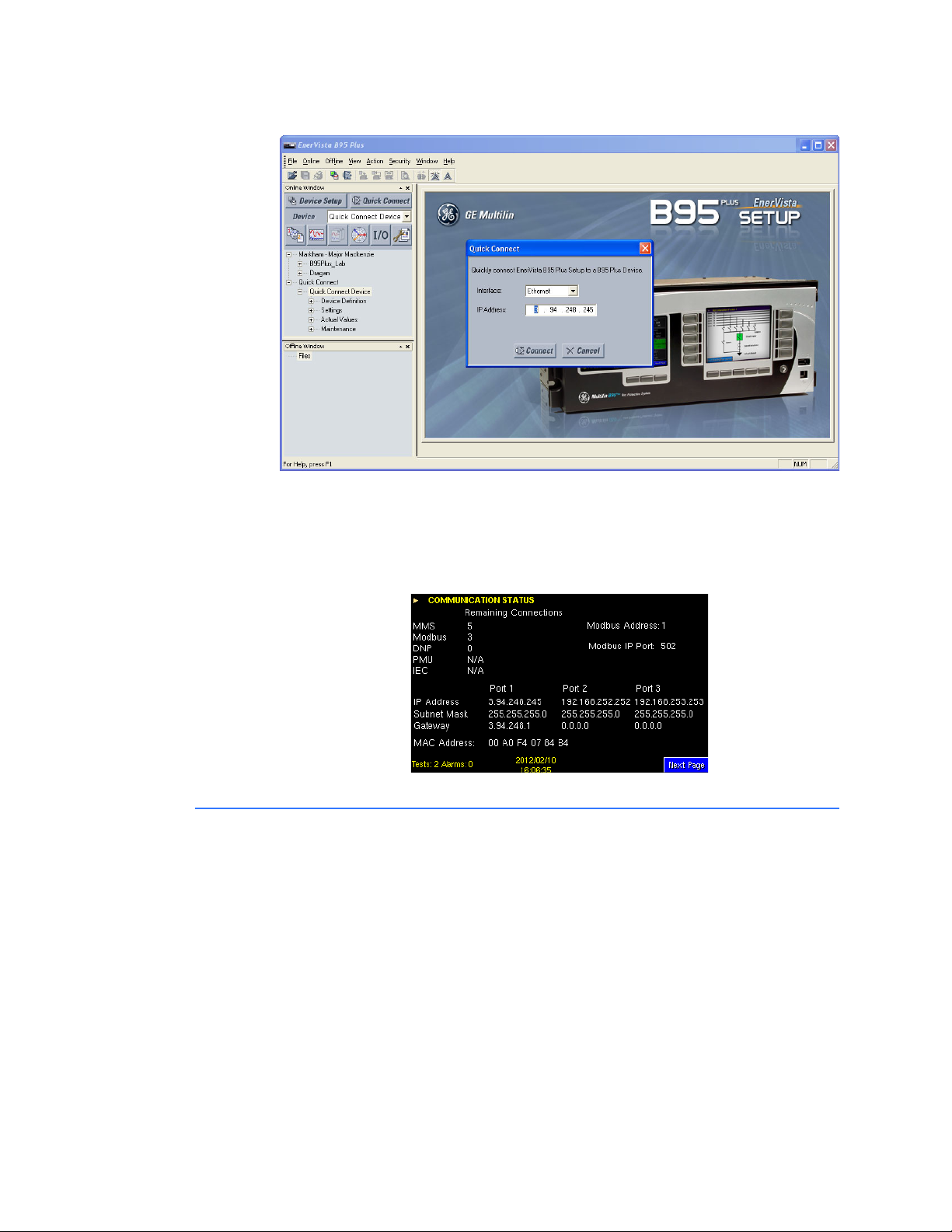
ADDING SITES AND DEVICES CHAPTER 4: ENERVISTA SOFTWARE
Figure 6: Using the Ethernet port to establish communication to the B95
To view the relay’s IP address when the B95
Plus
is already in operation:
Plus
1. On the relay’s front panel, press the Next Page button below the annunciator display
to the Communications Status page to view the IP address of the relay’s Ethernet port
chosen for communication.
Figure 7: Viewing the IP address on the unit
Adding sites and devices
The EnerVista software allows for multiple B95
Communications parameters are organized in a hierarchical tree structure, with “sites” at
the top level and devices (each a B95
number of devices. There are four options to add sites and devices, as follows:
•The Device Setup button in the software window
• Right-clicking in the Online Window area of the software window and selecting
Device Setup
•The Edit Device Setup icon on the tool bar
•Clicking the Online > Device Setup menu option
Use one of these options to configure the sites and devices now. One example follows.
To add a site and device to the software:
Plus
devices to be run from it.
Plus
) allocated to specific sites. Sites can contain any
34 MULTILIN B95
Plus
BUS PROTECTION SYSTEM – INSTRUCTION MANUAL
Page 45
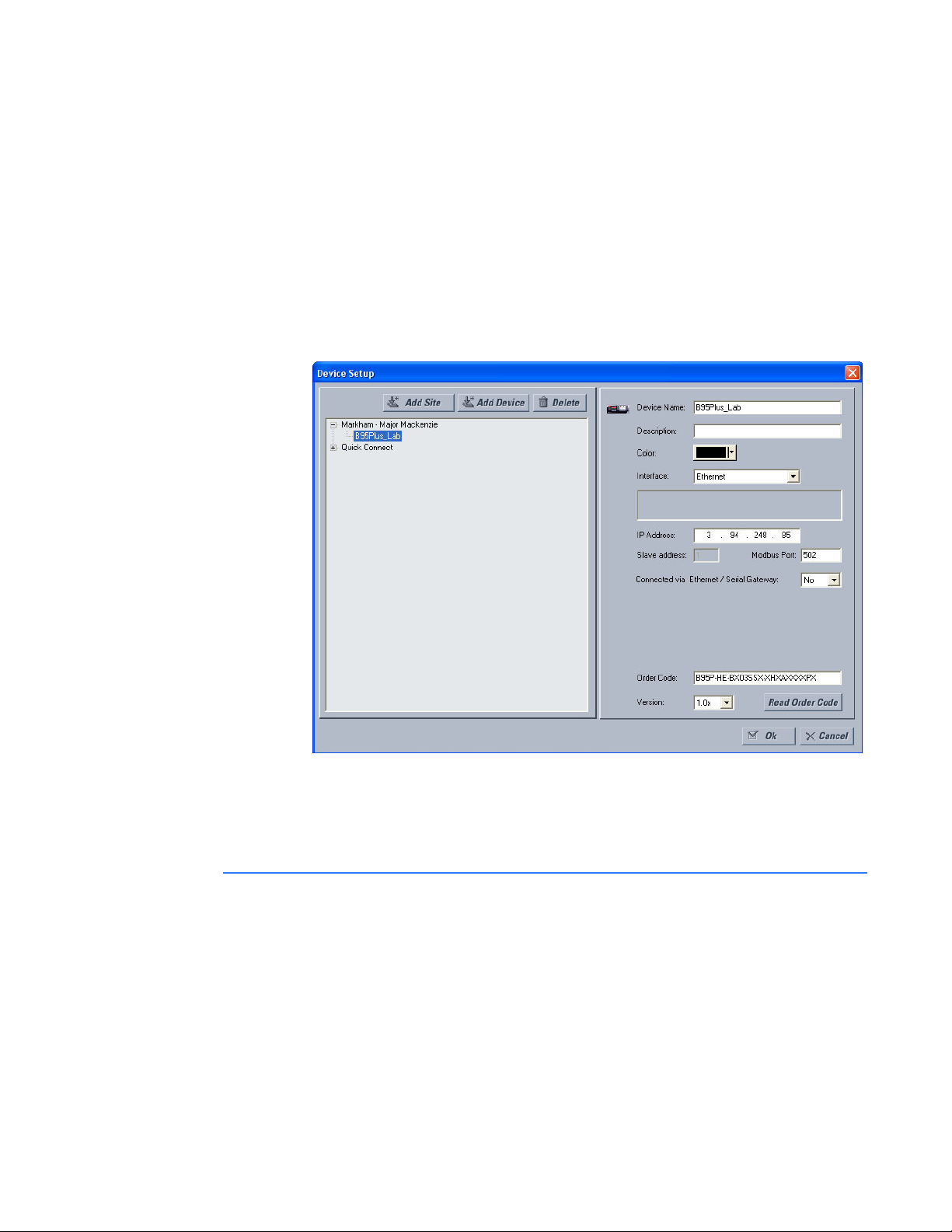
CHAPTER 4: ENERVISTA SOFTWARE CONNECTING TO A DEVICE
1. Click the Device Setup button.
2. Click the Add Site button in the window that opens.
3. Change the Site Name field to a descriptive name.
4. Click the Add Device button.
5. Change the Device Name field to a descriptive name.
6. From the Interface drop-down list, select Ethernet to connect to the B95
Plus
device
over a network.
7. Add the IP address.
8. Click the Read Order Code button.
9. Click OK to exit from the window.
Figure 8: Adding sites and devices
MULTILIN B95
Once configured, online connection to a particular B95
Plus
can be established by
navigating to the device in the Online Window area of the software. Files dragged and
dropped into that part of the software window are sent automatically to the online
communicating device.
Connecting to a device
The usual method to access a device is to click Quick Connect.
To access a device using the software:
1. In the Online Window area of the EnerVista software, double-click the Quick Connect
menu item.
2. Double-click the Quick Connect Device menu item. The information loads.
Plus
BUS PROTECTION SYSTEM – INSTRUCTION MANUAL 35
Page 46

ACCESSING SETTINGS CHAPTER 4: ENERVISTA SOFTWARE
Accessing settings
Three features facilitate selection and navigation:
• Quick select for operands
• Screen navigation feature for long lists
• Expanding and collapsing a settings table
Operand quick select
Using different mouse gestures, the user is able to initiate three different logic operand
selection modes in the B95
• By right-clicking on the far right side of any logic operand setting entry field, a dropdown list of all logic operands opens. In this mode, the user can use the scroll-bar to
scroll through the list until the required logic operand is visible, then click it to select it
and close the list. The user can also type a letter on the keyboard to jump down the list
to the next operand with a name starting with that letter.
• By right-clicking twice anywhere except the far right side of any logic operand setting
entry field, the field opens for keyboard entry of the operand name. (The first click
opens the operand quick select popup described as follows.) In this mode, as each
character is typed, the characters to the right are replaced to match the first operand
that matches the characters up to and including the new character. Characters that
do not match an operand are not accepted. Windows operating system's select, copy
and paste features also can be used in this mode.
• By single-clicking anywhere except the far right side of any logic operand setting entry
field, the logic operand quick select window opens. The window is generally as shown
in the figure that follows. The left-hand side displays a tree structure containing logical
groups of operands, and the right-hand side shows the operands of the tree element
selected.
Double-clicking an operand in the right-hand window or single-clicking an operand
and clicking Ok selects that operand and closes the window.
Plus
, as follows:
36 MULTILIN B95
Plus
BUS PROTECTION SYSTEM – INSTRUCTION MANUAL
Page 47

CHAPTER 4: ENERVISTA SOFTWARE ACCESSING SETTINGS
Figure 9: Accessing operands using quick select feature
Operands associated with process cards not present in the order code do not display.
Operands associated with process cards that are present in the order code display
whether or not they are associated with bricks that are disabled or not connected.
Navigating long lists
For tables with many columns, a feature allows you to navigate quickly to a column.
The feature uses the Parameter and ID fields at the top of the table. Simply click the
Parameter field to select a column to which to navigate. Or select the ID field and select a
specific entry. For both fields, you can also type a letter to have the software jump to the
first entry starting with that letter. To exit without selecting, press the Esc key.
In the example shown, ID was clicked and there are two options from which to select, CB3
and CB5.
Figure 10: Using the drop-down list to navigate columns
MULTILIN B95
Plus
BUS PROTECTION SYSTEM – INSTRUCTION MANUAL 37
Page 48

VIEWING ACTUAL VALUES CHAPTER 4: ENERVISTA SOFTWARE
Expanding/collapsing table rows
For tables in the EnerVista software with numerous rows, the rows are generally collapsed
when the window opens. Simply click the row heading, which is typically a grey box with
bold text, to expand content. In the example shown, the General Settings rows have been
expanded.
The ID row at the top of the table is always expanded and cannot be collapsed.
Figure 11: Bus sources settings
Viewing actual values
Actual values refers to live data. You can view real-time data from the B95
input/output status and measured parameters.
To view data:
1. In the Online Window area of the EnerVista software, navigate to the Actual Values
entry.
Information on actual values is outlined in applicable sections later in this document.
Viewing event records
The events recorder in the B95
signals monitored by the unit. These signals can include the state of circuit breakers and
disconnect switches, external alarms and indications, and any of the internal functions of
the device. The B95
on each process card. Once this memory is filled, the oldest events are overwritten. Events
are displayed in chronological order from most recent to oldest.
Most B95
most functions, and state changes for FlexLogic
written to the events recorder. When the setting is disabled, state changes for the element
are not recorded.
The following procedures outline how to view event records and enable/disable event
recording. See the Event Recorder section later in the document for information on how to
compare event records and how to access the records on the B95
To view the event records of a B95
1. In the Online Window area of the EnerVista software, navigate to Actual Values >
Plus
DFR > Event Record. The event record displays.
Plus
can store a total of 4,096 events on the main card and 4,096 events
elements contain an events setting. Event recording is enabled by default for
Plus
, such as
Plus
provides a time-stamped record of state changes of
operands associated with the element are
Plus
.
Plus
device:
38 MULTILIN B95
Plus
BUS PROTECTION SYSTEM – INSTRUCTION MANUAL
Page 49

CHAPTER 4: ENERVISTA SOFTWARE VIEWING TRANSIENT RECORDS
2. Click the Refresh button whenever the screen needs to be updated with the recent
events.
Figure 12: Viewing event records
An example follow for enabling/disabling event recording.
To enable/disable bus differential event recording of a B95
1. In the Online Window area of the EnerVista software, navigate to Settings >
Protection > General > Bus Differential.
2. View the Events field.
Viewing transient records
Transient records are detailed data records covering short periods of time. The
Plus
B95
the ability to view oscillography waveform traces and digital states in a visual display of
power system and relay operation data for specific triggered events.
To view transient records in the software:
1. In the Online Window area, navigate to Actual Values > DFR > Transient Recorder,
records up to 128 samples per cycle for the transient records. EnerVista includes
select the required record, and click the Read button to recover the record and start
the Comtrade waveform viewer. The records can also be retrieved from the EnerVista
software event record screen by double-clicking the transient record’s icon, which is
located on the right side of the event record window.
Plus
device:
MULTILIN B95
Plus
BUS PROTECTION SYSTEM – INSTRUCTION MANUAL 39
Page 50

SETTINGS FILES CHAPTER 4: ENERVISTA SOFTWARE
Figure 13: Transient record retrieval screen
To manually force a trigger of the transient recorder, use the transient retrieval screen
shown. Click the Force Trigger button.
To clear transient records, use the Actual Values > DFR > Transient Recorder > Command
screen.
Settings files
Settings files contain device and configuration information. They are used to apply new
settings to devices, or to restore previously saved settings. They are organized by file
names assigned by the user. Settings files contain data pertaining to the following types of
relay settings:
• Device definition
•General
• Communications (station bus interface)
• Remote resources (process bus interface)
• Protection (protection elements, FlexLogic, Isolators, Group Control)
• Digital fault recorder (DFR), including transient recorder and Event Recorder
• Front panel
•Security
• Configure FlexOperands (assigning application-specific names)
Settings files have .urs file extensions.
The EnerVista software supports the following three ways of handling changes to relay
settings:
• In offline mode (relay disconnected) to create or edit relay settings files for later
download to communicating relays
• In online mode (relay connected) to directly modify any relay settings via relay data
view windows, and then later save the settings to a file
• Create/edit settings files offline while connected to the relay, then write them to the
relay
Factory default values are supplied and can be applied after any changes.
The following settings are not transferred to the B95
• Relay Settings Programmed/Not Programmed
• Modbus TCP Port Number
Plus
with settings files:
40 MULTILIN B95
Plus
BUS PROTECTION SYSTEM – INSTRUCTION MANUAL
Page 51

CHAPTER 4: ENERVISTA SOFTWARE DEPLOYING SETTINGS FILES TO MULTIPLE DEVICES USING SETTINGS TEMPLATES
•IP Address
•IP Subnet Mask
• Gateway IP Address
• Network Address NSAP
• IEC61850 Config GOOSE ConfRev.
Deploying settings files to multiple devices using settings templates
Settings templates simplify the configuration of multiple devices that protect similar
assets. In these situations, typically a large number of settings are identical among
devices, reflecting a common bus architecture and protection approach. The templates
allows engineers to configure and test these common settings, then lock them so they are
not available to others. For example, these locked-down settings can be hidden from view
to field engineers, allowing them to quickly identify and concentrate on the settings
specific to their application. The site-specific settings can be specified as editable and
made available to field engineers installing the devices. These are settings such as
protection element pickup values and current transformer (CT) and voltage transformer
(VT) ratios.
The settings template mode allows the user to define which settings are visible in the
EnerVista B95
(settings file templates) and online devices (online settings templates). The functionality is
identical for both purposes. When in template mode, only settings that are available for
editing are saved to the device or setting file during the read/write process.
This section outlines how to enable and edit the templates.
Plus
Setup software. Settings templates can be applied to both settings files
Enabling the settings template in offline mode
The settings file template feature is disabled by default.
To enable the settings template while in offline mode:
1. Select a settings file from the Offline Window area of the EnerVista software.
2. Right-click the selected settings file and select Settings File Template > Create
Template. When the option does not display, it means that the template is already
enabled.
The settings file template is now enabled and the file tree displayed in light blue. The
settings file is now in template editing mode (shown).
Figure 14: Enabled settings template
MULTILIN B95
Plus
BUS PROTECTION SYSTEM – INSTRUCTION MANUAL 41
Page 52

DEPLOYING SETTINGS FILES TO MULTIPLE DEVICES USING SETTINGS TEMPLATES CHAPTER 4: ENERVISTA SOFTWARE
Enabling the settings template in online mode
The settings file template feature is disabled by default.
To enable the settings template while in online mode:
1. Select an installed device in the Online Window area of the EnerVista software.
2. Right-click the device and select Template Mode > Create Template. If the option
does not display, it means that the template is already enabled.
Figure 15: Enabling the template
3. In the password window that appears, enter and re-enter a password, then click OK.
The password is for the template and must be at least four characters in length.
Figure 16: Entering a settings file password
The online settings template is now enabled. The device is now in template editing mode.
Editing a settings template
The template editing feature is used to specify which settings are available for viewing and
modification in the EnerVista software. By default, all settings except the
FlexLogic
To edit a settings file template:
1. Right-click an installed device or a settings file on the left side of the EnerVista
2. Select Template Mode > Edit Template (online mode) or Settings File Template > Edit
3. Enter the template password (if required) then click OK.
4. Navigate to and select the relevant settings windows that contain settings to be
equation editor settings are locked.
software.
Template (offline mode) to place the device or settings file in template editing mode.
specified as viewable. In the example shown, Protection > General > Bus Sources
was selected.
42 MULTILIN B95
Plus
BUS PROTECTION SYSTEM – INSTRUCTION MANUAL
Page 53

CHAPTER 4: ENERVISTA SOFTWARE DEPLOYING SETTINGS FILES TO MULTIPLE DEVICES USING SETTINGS TEMPLATES
By default, settings specified as locked display with a grey background. The Edit icon
on the upper right of the settings window indicates that software is in edit mode.
5. Specify which settings to make viewable by clicking them.
The settings selected as available to view display in yellow.
6. Click Save to save changes to the settings template.
Only the settings that are available for editing are saved to the device or setting file.
Adding password protection to a settings template
To maximize security, save a template with password protection.
To add password protection to a settings file template:
1. Right-click a settings file in the Offline Window area of the EnerVista software.
2. Select Settings File Template > Password Protect Template. When the option is not
available, it means that the template is not active or that a password already exists. To
activate the template, select the Create Template option.
Figure 17: Template password entry window
3. In the password window that appears, enter and re-enter a password, then click OK.
The password is for the template and must be at least four characters in length.
The settings file template is now secured with password protection.
MULTILIN B95
Plus
BUS PROTECTION SYSTEM – INSTRUCTION MANUAL 43
Page 54

DEPLOYING SETTINGS FILES TO MULTIPLE DEVICES USING SETTINGS TEMPLATES CHAPTER 4: ENERVISTA SOFTWARE
NOTE:
When templates are created for online settings, the password can be added during the
initial template creation step. It does not need to be added after the template is created.
Applying a settings template
Once all necessary settings are specified for viewing, users can use the settings template
on the online device or the settings file.
To display only the settings available for editing:
1. Right-click an installed device or a settings file at the left side of the EnerVista
software.
2. Select Template Mode > View in Template Mode (online mode) or Settings File
Template > View in Template Mode (offline mode).
3. Enter the template password (if required) then click OK to apply the template.
Once the template has been applied, users are only able to view and edit the settings
specified by the template. The effect of applying the template to the bus source settings is
shown. The white fields can be changed. The grey fields cannot be changed.
Figure 18: Setting window view via the View in Template Mode command
Viewing in template mode also modifies the panels displayed in the software, showing
only the settings categories that contain editable settings. The effect of applying the
template is shown as follows. In the first figure the template has not been applied and all
menu items display. In the second figure, the template has been applied and only the Bus
Source item displays.
Figure 19: Settings template not applied
44 MULTILIN B95
Plus
BUS PROTECTION SYSTEM – INSTRUCTION MANUAL
Page 55

CHAPTER 4: ENERVISTA SOFTWARE BUS REPLICA GRAPHICAL EDITOR
Figure 20: Settings template applied
Removing a settings template
It can be necessary to remove a settings template. Upon removal, it cannot be reapplied
and a new settings template is required.
To remove a template:
1. Right-click an installed device or settings file on the left side of the EnerVista software.
2. Select Template Mode > Remove Template (online mode) or Settings File Template >
Remove Settings Template (offline mode).
3. Enter the template password (if required) and click OK to continue.
4. Verify that you want to remove the template by clicking Yes.
Figure 21: Confirming settings template removal
The EnerVista software removes all template information and all settings are available.
Bus replica graphical editor
A bus replica graphical editor is provided as an alternate means of entering settings and
visualizing the behavior of the bus replica. The bus replica is the means by which the
Plus
B95
later chapters. Dynamic buses in particular elicit complex bus replica behavior, which can
be difficult to visualize using only the usual matrixes of settings. Graphical presentation
facilitates visualization.
The graphical editor operates on settings related to configuring the bus replica. Basically,
the graphical editor allows a schematic diagram of the protected bus to be constructed,
and by clicking on the isolators, breakers, and CTs in the diagram, settings entered that fit
the diagram to the actual bus. These settings are the same settings that can also be
configured by the usual methods from screens containing matrixes of settings, although
there are restrictions on opening both the matrix screens and the graphical editor at the
same time. The graphical editor also has a few "virtual settings" concerning the graphical
presentation that are not accessible from the matrix screens, but none of these affect relay
operation.
This section contains instructions on the use of the graphical editor. The effect of the
settings the graphical editor accesses on relay behavior and guidance on setting their
values are contained in following chapters.
determines moment-by-moment the extent of each differential zone, as detailed in
MULTILIN B95
Plus
BUS PROTECTION SYSTEM – INSTRUCTION MANUAL 45
Page 56

BUS REPLICA GRAPHICAL EDITOR CHAPTER 4: ENERVISTA SOFTWARE
NOTE
The bus graphical editor does not display dynamic open/close status of the isolators and
breakers. It displays only how they are arranged.
NOTE:
The bus replica graphical editor displays only bus sources that are selected for display. It is
possible for enabled bus sources that therefore are contributing to protection operation to
be omitted from the display, and as a result their contribution overlooked by personal
using the display. Verification of the presence on the graphical display of all bus sources
shown as enabled on the Settings > Protection > General > Bus Sources screen is highly
recommended.
The following figure shows as an example a completed diagram. The wide short boxes
stacked vertically on the left side are bus zone labels, the horizontal lines extending from
them to the right are each a bus zone representation. The tall boxes to the right are each a
representation of a bus source.
46 MULTILIN B95
Plus
BUS PROTECTION SYSTEM – INSTRUCTION MANUAL
Page 57
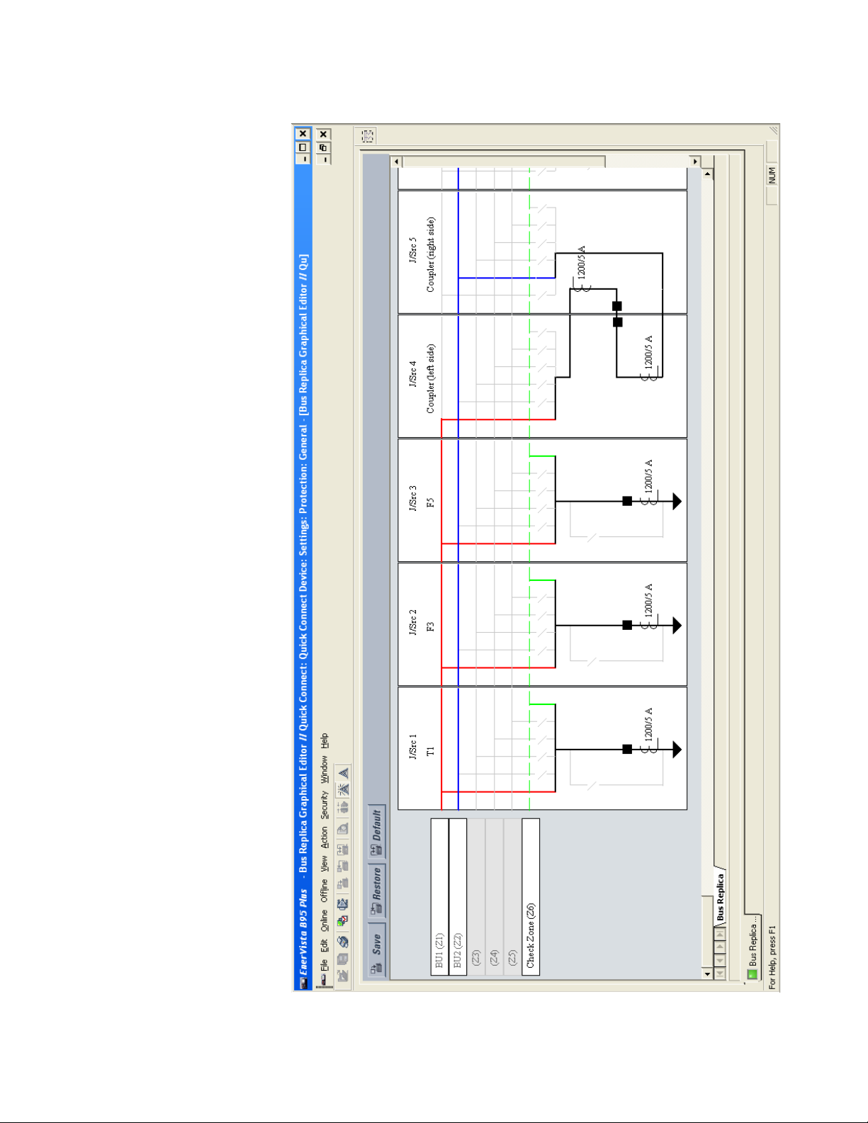
CHAPTER 4: ENERVISTA SOFTWARE BUS REPLICA GRAPHICAL EDITOR
Figure 22: Bus replica graphical editor example
MULTILIN B95
Plus
BUS PROTECTION SYSTEM – INSTRUCTION MANUAL 47
Page 58

BUS REPLICA GRAPHICAL EDITOR CHAPTER 4: ENERVISTA SOFTWARE
The following figure shows the symbols used in each bus source representation. The backslash ("\") symbols represent bus or bypass isolators, the solid squares represent circuit
breakers, the triangles represent network elements, and the double arc symbols represent
CTs.
Figure 23: Symbols used in a bus source
An isolator can display three ways. First, it is greyed-out when its dynamic status
connection setting is set to OFF (for example if there is a permanent primary open circuit at
that position). To set it to OFF, you double-click the isolator and select the “Isolator Does
Not Exist" option. Second, when you select the “Solid Connection” option, the isolator is ON
and displays as a straight-through connection (for example if there is a permanent primary
connection in that isolator's position). Third, the isolator displays as a disconnected slash
when the setting is set to any logic operand other than OFF or ON (for example if there is
an actual primary isolator at that position).
Figure 24: Setting an isolator as on or off
48 MULTILIN B95
Plus
BUS PROTECTION SYSTEM – INSTRUCTION MANUAL
Page 59

CHAPTER 4: ENERVISTA SOFTWARE BUS REPLICA GRAPHICAL EDITOR
A circuit breaker is greyed-out when its breaker opened settings are both set to OFF,
indicating that the zone expansion/reduction feature is not deployed.
The CT drawing convention used here is that an instantaneously positive primary current
entering one side of the CT symbol results in an instantaneously positive secondary current
exiting the same side of the CT symbol. That is to say, if polarity marks were to be drawn on
the symbol, then primary and secondary marks are on the same side of the symbol. The
side of the CT with the longer tail represents the side of the CT that connects to the Brick.
Thus when the tail is on the side away from the bus, primary current flowing into the bus
results in a positive relay current. If the CT origin settings are both None (meaning there is
no actual CT), the CT symbol is greyed-out.
To configure the bus replica using the bus replica graphical editor:
1. In the Online Window area of the software, navigate to Settings > Protection >
General > Bus Replica Graphical Editor.
2. Double- click the bus zone label of each bus zone to be used, and in the Bus Zone
Properties window that opens, enter an ID descriptive of the bus segment to be
protected. Also select the required function and zone type setting. Click OK to close the
window.
3. Add the required bus sources. To add a bus source to the right of all existing sources
on the diagram, click the icon at the top right of the window shown in the following
figure. To add a bus source to the left of an existing source, right-click the existing
source and select the Insert Bus Source option.
MULTILIN B95
4. In the Bus Source Properties window that opens on adding a bus source, select the
designation of the required bus source from the Source drop-down list. Next, while
still in the Bus Source Properties window, enter an ID descriptive of the bay modelled
by the bus source. Also select the required function and events setting, and the
operand to use for bus source block feature. Select the appropriate Graphical
Presentation icon that best represents the arrangement of the CTs and breaker in the
bus source. Click OK to close the window.
5. Double-click each of the isolator, breaker, and CT symbols, and in the window that
open, adjust the presented settings appropriately.
Plus
BUS PROTECTION SYSTEM – INSTRUCTION MANUAL 49
Page 60

SECURING AND LOCKING FLEXLOGIC EQUATIONS CHAPTER 4: ENERVISTA SOFTWARE
6. Double-click anywhere inside a bus source except over an isolator, CT, or breaker to
re-open the Bus Source Properties window when bus source setting changes are
required.
7. Right-click a bus source and select the Hide Bus Source option to remove a bus
source no longer wanted in that position on the diagram. This action does not disable
the bus source; it only removes the bus source from the diagram. Once removed, a
bus source can be inserted in a different location as described in step 3.
Note that the Copy Special option copies the diagram to the Windows paste buffer as a
bitmap. The bitmap can then be pasted into other documents using programs such as
Word or Paint.
Securing and locking FlexLogic equations
The B95
Plus
allows users to secure parts or all of a FlexLogic equation, preventing
unauthorized viewing or modification of critical FlexLogic
This is accomplished using the settings template feature to lock individual entries within
FlexLogic
retrieved from any B95
equations. Secured FlexLogic equations remain secure when files are sent to and
Plus
device.
Use the following procedures.
Locking FlexLogic equation entries
To lock individual entries of a FlexLogic equation:
1. Right-click the settings file or online device on the left side of the EnerVista software.
and select Template Mode > Edit Template. If the template has not already been
enabled, click Settings File Template > Create Template or Template Mode > Create
Template.
2. In the same navigation tree, navigate to Settings > Protection > Main Card FlexLogic
> FlexLogic Equation Editor.
By default, all FlexLogic entries are viewable and display against a yellow background.
The icon on the upper right of the window indicates that the software is in edit mode.
3. Specify the entries to lock by clicking them.
The locked entries display against a grey background.
Figure 25: Locking FlexLogic entries using the template
applications.
4. Click the Save button.
50 MULTILIN B95
Plus
BUS PROTECTION SYSTEM – INSTRUCTION MANUAL
Page 61

CHAPTER 4: ENERVISTA SOFTWARE SETTINGS FILE TRACEABILITY
Locking a settings file and FlexLogic equations to a serial number
A settings file and associated FlexLogic equations can be locked to a B95
Once the FlexLogic
entries in a settings file have been secured, use the following procedure
to lock the settings file to a serial number.
1. Right-click the settings file in the Offline Window area and select Manage Settings
File > Edit Properties.
The following window displays.
Figure 26: Locking the settings file to a device
Plus
serial number.
2. Enter the serial number of the B95
Lock field. To view the serial number, look for the bar code on the back of the unit,
navigate to Actual Values > Product Information > Model Information in the Online
Window area of the software, or page down in the annunciator display on the front of
the unit.
3. Click OK. The settings file and FlexLogic equations are now locked to the B95
specified.
Settings file traceability
A traceability feature allows the user to determine if the settings in a B95
been changed since installation from a settings file.
To determine if settings have changed since installation:
1. Simply right-click in the Online Window area and select Compare with Settings File.
The number of differences then a list of differences displays.
Plus
device to lock to the settings file in the Serial #
Plus
Plus
device have
device
MULTILIN B95
Plus
BUS PROTECTION SYSTEM – INSTRUCTION MANUAL 51
Page 62

SETTINGS FILE TRACEABILITY CHAPTER 4: ENERVISTA SOFTWARE
Figure 27: List of settings file differences
52 MULTILIN B95
Plus
BUS PROTECTION SYSTEM – INSTRUCTION MANUAL
Page 63

GE Energy
Plus
Multilin B95
Bus Protection
System
Chapter 5: Settings – General
Settings – General
This chapter and subsequent chapters on Communications, Remote Resources, Protection,
Digital Fault Recorder, Front Panel, and Security describe features on a presentation
structure that facilitates comprehension by the settings engineer. This chapter describes
general features whose settings appear in the software under Settings > General.
Installation
After installation of the Multilin B95
software, and addition of the B95
device with the relay name.
To configure or view installation information:
1. In the Online Window area of the software, navigate to Settings > General >
Installation.
2. Click the right side of a field to access any drop-down list, for example to the right of
“Not Programmed.” Otherwise, click a field to change the setting.
3. Click Save when done.
Figure 1: General installation information
The following settings are available.
Plus
Bus Protection System, installation of the EnerVista
Plus
device to the software, start configuration of the
MULTILIN B95
Plus
BUS PROTECTION SYSTEM – INSTRUCTION MANUAL 53
Page 64

POWER SYSTEM CHAPTER 5: SETTINGS – GENERAL
Relay Settings
Range: Programmed, Not Programmed
Default: Not Programmed
To safeguard against the installation of a device without any entered settings, the
Plus
does not allow signaling of any output relay until this setting value is
B95
“Programmed.” The
UNIT NOT PROGRAMMED self-test error message displays on the
front panel self-test summary page until it is put into the programmed state. Normally,
you set the value to “Programmed” after configuring all the Settings panels and the unit
is ready to go into service. You do this manually while online using this field;
downloading a settings file does not change this setting.
Relay Name
Range: up to 20 characters
Default: -----
This setting allows the user to uniquely identify a relay. This name appears on all
generated reports and displays and on the front panel Product Information page as the
Relay ID.
User Configuration Name
Range: up to 20 characters
Default: Initial
This setting allows the user to provide a description for the settings that are loaded at a
particular time (for example, “Spring-summer settings”). This description displays on the
Product Information page of the front panel as the Configuration field.
User Configuration Date
Range: up to 20 characters
Default: -----
Plus
This setting records the date of last setting change through the B95
software. Each
time any settings are changed or a new settings file loaded, this value updates. This
description also displays on the front panel Product Information page as the
Configuration Date.
Power system
The power system includes the following items: nominal frequency; frequency tracking
function; frequency and phase reference; current cutoff level; and voltage cutoff level.
Configure these for first setup.
To configure or view power system information:
1. In the Online Window area of the software, navigate to Settings > General > Power
System.
Figure 2: Frequency and voltage information
54 MULTILIN B95
Plus
BUS PROTECTION SYSTEM – INSTRUCTION MANUAL
Page 65

CHAPTER 5: SETTINGS – GENERAL POWER SYSTEM
NOTE
Nominal Frequency
Range: 50 Hz, 60 Hz
Default: 60 Hz
This value is used as a default to set the digital sampling rate if the system frequency
cannot be measured from available signals. This can happen if the Frequency Tracking
Function is Disabled, the Frequency and Phase Reference setting is None, or the signals
are not present or are heavily distorted. Before reverting to the nominal frequency, the
frequency tracking algorithm holds the last valid frequency measurement for a safe
period of time while waiting for the signals to reappear or for the distortions to decay.
Frequency Tracking Function
Range: Disabled, Enabled
Default: Enabled
This setting is set to “Disabled” only in unusual circumstances; consult GE Multilin for
special variable-frequency applications.
Frequency And Phase Reference
Range: None, all bus sources, and all voltage sources
Default: None
This setting determines which signal source is used (and hence which AC signal) for
frequency tracking and phase angle reference. The Clarke transformation of the phase
signals is used for frequency metering and tracking (V
= (2VA – VB –VC) / 3) for better
FREQ
performance during fault, open pole, and voltage transformer (VT) and current
transformer (CT) fail conditions.
The reference signal phase angle always displays zero degrees and all other phase
angles are relative to this signal. If the pre-selected reference signal is not measurable at
a given time, the phase angles are not referenced and typically continuously rotate.
The phase angle referencing is done via a phase locked loop, which can synchronize
independent B95
Plus
devices if they have the same AC signal reference. This results in
precise correlation of time tagging in the event recorder between different devices
during periods of IRIG-B unavailability. Note that the other devices are not typically
B95
Plus
units; they are UR or UR
Plus
devices or from other vendors.
Current Cutoff Level
Range: 0.002 to 0.020 per unit (pu) in steps of 0.001
Default: 0.020 pu
This setting modifies the current cutoff threshold. Very low currents (0.2 to 2% of the
rated value) are very susceptible to noise. Some customers prefer low currents to display
as zero, while others prefer the current to be displayed even when the value reflects
noise rather than the actual signal. The B95
Plus
applies a cutoff value to the magnitudes
and angles of the measured currents. If the magnitude is below the cutoff level, it is
substituted with zero. This applies to phase current phasor values. The cutoff operation
applies to quantities used for metering, general protection, and control, as well as those
used by communications protocols. Raw current samples available via oscillography are
not subject to cutoff.
The bus differential algorithm does not use cutoff.
NOTE:
Lower this setting with care because the B95
Plus
accepts lower signals as valid
measurements. Unless dictated otherwise by a specific application, the default setting
of “0.020 pu” is recommended.
MULTILIN B95
Plus
BUS PROTECTION SYSTEM – INSTRUCTION MANUAL 55
Page 66

USER PROGRAMMABLE SELF-TESTS CHAPTER 5: SETTINGS – GENERAL
NOTE
Voltage Cutoff Level
Range: 0.1 to 1.0 volts secondary in steps of 0.1
Default: 1.0 volts secondary
This setting specifies the voltage cutoff threshold. Low secondary voltage
measurements (at the fractional volt level) can be affected by noise. Some customers
prefer these low voltages to be displayed as zero, while others prefer the voltage to be
displayed even when the value reflects noise rather than the actual signal. The
Plus
applies a cutoff value to the magnitudes and angles of the measured voltages. If
B95
the magnitude is below the cutoff level, it is substituted with zero. This operation applies
independently to phase voltages and to phase-to-phase voltages. The cutoff operation
applies to quantities used for metering, protection, and control, as well as those used by
communications protocols. Raw samples of the voltages available via oscillography are
not subject cutoff.
NOTE:
Lower this setting with care because the B95
Plus
accepts lower signals as valid
measurements. Unless dictated otherwise by a specific application, the default setting
of “1.0 V” is recommended.
User programmable self-tests
The B95
Plus
performs self-tests to verify relay integrity. There are the two types of self-tests:
major and minor. These tests are itemized in the Maintenance chapter. The settings
described in this section allow certain self-tests to be enabled or disabled to meet
requirements of the application.
To configure self-tests:
1. In the Online Window area of the software, navigate to Settings > General > User
Programmable Self Test.
Figure 3: Self-test settings
The following settings are available.
Remote Device Off Function
Range: Enabled, Disabled
Default: Enabled
When this setting is Enabled, the REMOTE DEVICE OFF self-test operates as described in
the minor self-tests section of the Maintenance chapter. When Disabled, this self-test
does not alarm.
56 MULTILIN B95
Plus
BUS PROTECTION SYSTEM – INSTRUCTION MANUAL
Page 67

CHAPTER 5: SETTINGS – GENERAL USER PROGRAMMABLE SELF-TESTS
Ethernet Port 1…3 Fail Function
Range: Enabled, Disabled
Default: Disabled
When this setting is Enabled, the ETHERNET PORT 1…3 FAILURE self-tests operate as
described in the minor self-tests section of the Maintenance chapter. When Disabled,
this self-test does not alarm.
SNTP Fail Function
Range: Enabled, Disabled
Default: Enabled
When this setting is Enabled, the SNTP FAILURE self-test operates as described in the
minor self-tests section of the Maintenance chapter. When Disabled, this self-test does
not alarm.
IRIG-B Fail Function
Range: Enabled, Disabled
Default: Enabled
When this setting is Enabled, the IRIG-B FAILURE self-test operates as described in the
minor self-tests section of the Maintenance chapter. When Disabled, this self-test does
not alarm.
Configurable Major Self-Test
Range: any FlexLogic operand
Default: OFF
When the operand selected by this setting is in the On state, this self-test is alarmed. This
allows the relay to use FlexLogic
or other means to generate an application specific
major self-test alarm, thereby taking the relay out of service.
MULTILIN B95
Plus
BUS PROTECTION SYSTEM – INSTRUCTION MANUAL 57
Page 68

USER PROGRAMMABLE SELF-TESTS CHAPTER 5: SETTINGS – GENERAL
58 MULTILIN B95
Plus
BUS PROTECTION SYSTEM – INSTRUCTION MANUAL
Page 69

GE Energy
Plus
Multilin B95
Bus Protection
System
Chapter 6: Communications
Communications
This chapter outlines how to program the Multilin B95
communication settings.
System
Communications overview
The B95
ports (ports 2 and 3) on the communications module. Each port supports 100Base-FX over
multimode fiber and 10/100Base-TX over twisted-pair, with auto-negotiation. Port 1 is
primarily intended for configuration and file retrieval purposes. Ports 2 and 3 are intended
for supervisory control and acquisition data (SCADA) and peer-to-peer messaging. The
following protocols are available, depending on the order code of the unit.:
• Ethernet port 1 — Modbus TCP, TFTP, SNTP, HTTP
• Ethernet port 2 — Modbus TCP, DNP 3.0, IEC 60870-5-104, IEC 61850, SNTP, TFTP, HTTP
• Ethernet port 3 — Modbus TCP, DNP 3.0, IEC 60870-5-104, IEC 61850, SNTP, TFTP, HTTP
Plus
has one Ethernet port (port 1) on the main module and two additional Ethernet
Network settings
This section outlines configurable network settings, such as Ethernet, trivial file transfer
protocol (TFTP), and simple network time protocol (SNTP).
Plus
Bus Protection
MULTILIN B95
Ethernet
Each of Ethernet ports 1 to 3 have globally unique identifiers known as MAC addresses. The
MAC address of port 1 is displayed on the Product Information page of the annunciator
and in the EnerVista software under Actual Values > Product Information > Model
Information. The MAC address of port 2 is one greater than port 1, and the MAC address of
port 3 is one greater than port 2.
If not already done, configure the IP address of the B95
for use. Ethernet ports 2 and 3 can be configured for single or dual IP redundancy.
Plus
BUS PROTECTION SYSTEM – INSTRUCTION MANUAL 59
Plus
and enable the Ethernet ports
Page 70
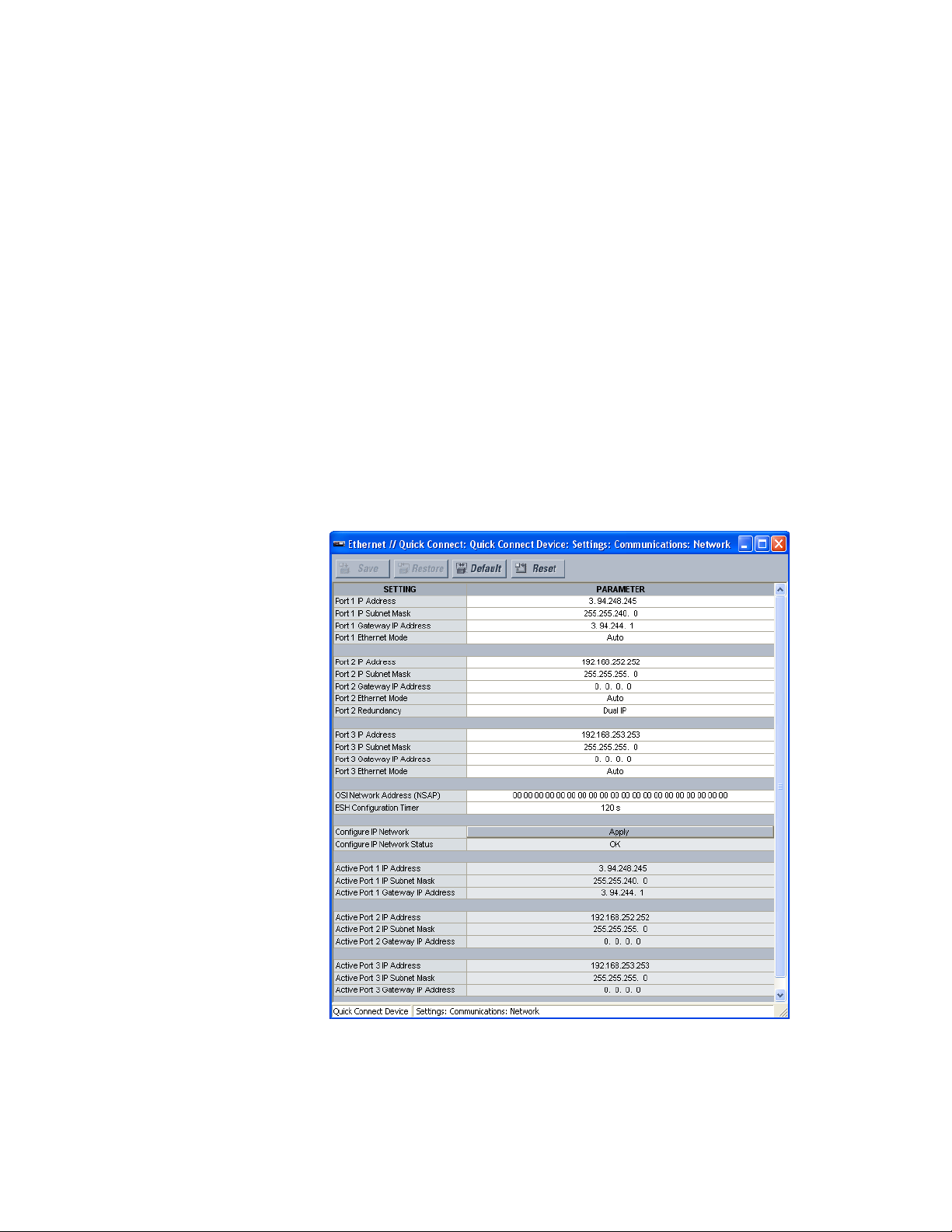
NETWORK SETTINGS CHAPTER 6: COMMUNICATIONS
In the single IP redundancy configuration, the port 2 IP address, subnet mask, and
gateway address are used for both ports 2 and 3, and the port 3 settings are ignored. All
communications traffic are normally routed on port 2. If a failure occurs (determined at the
hardware layer upon detecting loss of link signal on the active channel) then the traffic is
re-routed to port 3. Switchover to port 3 takes place in less than 10 ms from the moment
that the physical layer detects a failure. The device reverts from port 3 to port 2 as soon as
port 2 becomes available, regardless of the state of port 3. Switchover to port 2 takes place
in less than 500
ms. A link pulse is maintained in the transmit direction on both ports
regardless of the port in use. This ensures that communications are established with
minimal delays. An Ethernet broadcast message is transmitted immediately upon port
switch, thereby forcing all Ethernet switches in the network to immediately update their
routing tables.
In the dual IP redundancy configuration, each port has a unique IP address, with separate
subnet mask, and gateway address settings. Multiple client-server connections can be
opened on each port simultaneously. Under normal conditions, GOOSE messages are sent
on both ports and received on either.
To configure Ethernet settings:
1. In the Online Window area of the software, navigate to Settings > Communications
> Network > Ethernet to open the Ethernet configuration window.
2. After entering the addresses and settings, click the Save button then the Apply button.
Figure 1: Configuring Ethernet ports
The IP addresses are used with the DNP, Modbus/TCP, IEC 61580 MMS services, IEC 608705-104, SNTP, and TFTP protocols.
60 MULTILIN B95
Plus
BUS PROTECTION SYSTEM – INSTRUCTION MANUAL
Page 71

CHAPTER 6: COMMUNICATIONS NETWORK SETTINGS
NOTE:
When the NSAP address or any user map setting (when used with DNP) is changed, it
becomes active after power to the relay has been cycled (off-to-on).
The following settings are available for each Ethernet port, except for OSI Network
Address (NSAP) and ESH Configuration Timer, which are not port-specific, and the Port 2
Redundancy
, which applies only to Ethernet port 2.
Port 1, Port 2, Port 3 IP Address
Range: standard IP address range
Default: 192.168.251.251 (port 1), 192.168.252.252 (port 2), 192.168.253.253 (port 3)
These settings specify the dedicated IP address for each Ethernet port. Each port must
be configured for a different subnet. The IP address setting for port 3 is not available
when the Port 2 Redundancy setting is “Single IP.”
Port 1, Port 2, Port 3 IP Subnet Mask
Range: standard IP subnet mask range
Default: 255.255.255.0
These settings specify the dedicated subnet mask for each Ethernet port. Each port
must be configured for a different subnet, though the subnet masks can be identical.
The subnet mask setting for port 3 is not available when the Port 2 Redundancy setting
is “Single IP.”
Port 1, Port 2, Port 3 Gateway IP Address
Range: standard IP address range
Default: 0.0.0.0
These settings specify the gateway address for the selected Ethernet port . The setting
0.0.0.0 codes no gateway. Configure only one gateway for the relay and be sure to
configure this setting when using FTP and/or SNTP. Because only one port can declare a
gateway, the port selected in the SNTP settings is the port to declare the gateway
address.
The gateway IP address setting for port 3 is not available when the Port 2 Redundancy
setting is “Single IP.”
Port 1, Port 2, Port 3 Ethernet Mode
Range: Auto, 10/100 Base-TX, 100 Base-TX
Default: Auto
These settings select the Ethernet connection hardware type, either 10/100Base-TX
(twisted-pair) or 100Base-FX (fiber optic). The “Auto” selection is used to automatically
detect the Ethernet hardware type.
The Ethernet mode setting for port 3 is not available when the Port 2 Redundancy
setting is “Single IP.”
Port 2 Redundancy
Range: Single IP, Dual IP
Default: Dual IP
This settings selects single-IP or dual-IP operation for Ethernet ports 2 and 3. In single-IP
mode, the link status of both ports is continuously monitored but only one port is active
at a time. Each port uses the same source MAC address and IP parameters specified for
Ethernet port #2. In dual-IP mode, Ethernet ports 2 and 3 operate independently with
their own MAC addresses and IP parameters. Changes to this setting are implemented
immediately on saving.
OSI Network Address (NSAP)
Range: Any valid address
Default: 00 00 00 00 00 00 00 00 00 00 00 00 00 00 00 00 49 00 00 00
This setting specifies the NSAP address used with the IEC 61850 GSSE protocol over the
OSI (CLNP/TP4) stack.
MULTILIN B95
Plus
BUS PROTECTION SYSTEM – INSTRUCTION MANUAL 61
Page 72

NETWORK SETTINGS CHAPTER 6: COMMUNICATIONS
This address and the ESH Configuration Timer are not port-specific. When the NSAP
address is changed, it becomes active when power to the relay is cycled (off-to-on).
ESH Configuration Timer
Range: 0 to 32767 seconds in steps of 1
Default: 120 seconds
The End System to Intermediate System Routing Exchange protocol used with ISO 8473
mandates that the end system construct and transmit an End System Hello (ESH) signal
for each NSAP it serves, based on an internal timer. This setting specifies the
transmission time for the ESH signal. This setting takes affect when the B95
Plus
is
restarted.
The following commands are available from this window.
Configure IP Network
To make changes to the Ethernet settings outlined, save them, then click the Apply
button here.
This command validates the IP address, subnet mask, and gateway IP address settings
for all ports. When the validation is successful, the Configure IP Network Status value is
“OK” and the new settings take effect immediately. When the validation fails, the
Configure IP Network Status value indicates the reason for failure and the network
settings are restored to previous values.
The following actual values are available in this window.
Configure IP Network Status
Range: OK, PORT 1 NETMASK ERROR, PORT 2 NETMASK ERROR, PORT 3 NETMASK
ERROR, PORT 1 IP ADDR RSVD, PORT 2 IP ADDR RSVD, PORT 3 IP ADDR RSVD, PORT 1 IP
ADDR LPBK, PORT 2 IP ADDR LPBK, PORT 3 IP ADDR LPBK, PORT 1 IP ADDR NETWK,
PORT 2 IP ADDR NETWK, PORT 3 IP ADDR NETWK, PRT 1-2 SUBNET OVRLP, PRT 1-3
SUBNET OVRLP, PRT 2-3 SUBNET OVRLP, >1 GATEWAY DEFINED
This actual value displays the status of the Configure IP Network command. The
following status values are indicated:
– “OK”: All supplied user IP parameters are valid and have been applied to the
network stack.
– “PORT 1 NETMASK ERROR,” “PORT 2 NETMASK ERROR,” “PORT 3 NETMASK ERROR”:
An invalid network mask value was entered for Ethernet port 1, 2, or 3,
respectively.
– “PORT 1 IP ADDR RSVD,” “PORT 2 IP ADDR RSVD,” “PORT 3 IP ADDR RSVD”: A
reserved IP address was entered for Ethernet port 1, 2, or 3, respectively. Reserved
IP addresses include 0.---.---.--- (for self-identification), 224.---.---.--- through
239.---.---.--- (multicast), and 240.---.---.--- through 255.---.---.--- (reserved by
IANA).
– “PORT 1 IP ADDR LPBK,” “PORT 2 IP ADDR LPBK,” “PORT 3 IP ADDR LPBK”: A
loopback IP address was entered for Ethernet port 1, 2, or 3, respectively.
– “PORT 1 IP ADDR NETWK,” “PORT 2 IP ADDR NETWK,” “PORT 3 IP ADDR NETWK”:
The entered IP address is the network address for Ethernet port 1, 2, or 3,
respectively.
– “PRT 1-2 SUBNET OVRLP”: The entered network parameters for Ethernet port 1
overlap the network parameters for Ethernet port 2.
– “PRT 1-3 SUBNET OVRLP”: The entered network parameters for Ethernet port 1
overlap the network parameters for Ethernet port 3.
62 MULTILIN B95
Plus
BUS PROTECTION SYSTEM – INSTRUCTION MANUAL
Page 73

CHAPTER 6: COMMUNICATIONS NETWORK SETTINGS
– “PRT 2-3 SUBNET OVRLP”: The entered network parameters for Ethernet port 2
overlap the network parameters for Ethernet port 3.
– “>1 GATEWAY DEFINED”: The user has entered more than one default gateway.
Active Port 1, Port 2, Port 3 IP Address
Range: standard IP address range
These actual values display the configured IP address for each Ethernet port.
The active port IP address actual value for port 3 is not available when the Port 2
Redundancy setting is “Single IP.”
Active Port 1, Port 2, Port 3 IP Subnet Mask
Range: standard IP subnet mask range
These actual values display the configured subnet mask for each Ethernet port.
The active port subnet mask actual value for port 3 is not available when the Port 2
Redundancy setting is “Single IP.”
Active Port 1, Port 2, Port 3 Gateway IP Address
Range: standard IP address range
These actual values display the configured gateway address for the selected Ethernet
port.
The active port gateway address actual value for port 3 is not available when the Port 2
Redundancy setting is “Single IP.”
TFTP
Navigate to Actual Values > Communications > Communication and to Actual Values
> Communications > Remaining Connection to view additional actual values.
The trivial file transfer protocol (TFTP) can be used to transfer files from the B95
network. As such, the B95
from various sources, including Microsoft Windows XP. The dir.txt file obtained from
the B95
Plus
contains a list and description of all available files (for example, event records
Plus
operates as a TFTP server. TFTP client software is available
Plus
over a
and transient record oscillography).
To transfer the dir.txt file using TFTP:
1. On the Windows computer, open a command window. Use the ls and cd commands
to change to the folder in which you want to place the file.
2. Enter
tftp <B95Plus IP address> get dir.txt B95Plus_dir.txt
for example
tftp 3.94.248.245 get dir.txt B95Plus_dir.txt
copies the dir.txt file to the computer and names the file B95Plus_dir.txt
To configure TFTP:
1. In the Online Window area of the software, navigate to Settings > Communications
> Network > TFTP to open the TFTP configuration window.
MULTILIN B95
Plus
BUS PROTECTION SYSTEM – INSTRUCTION MANUAL 63
Page 74

NETWORK SETTINGS CHAPTER 6: COMMUNICATIONS
NOTE
Figure 2: TFTP configuration settings
The following settings are available.
TFTP Main UDP Port Number
Range: 1 to 65535 in steps of 1
Default: 69
This setting specifies the main user datagram protocol (UDP) port number.
TFTP Data UDP Port Number 1...4
Range: 0 to 65535 in steps of 1
Default: 0
These settings specify data for UDP port numbers 1 through 4. A TFTP data port value of
zero specifies that the B95
NOTE:
Changes to the TFTP protocol settings become active after power to the B95
Plus
is to automatically assign a port number.
Plus
has been
cycled (off-to-on).
SNTP
There are three options for setting the internal clock: simple network time protocol (SNTP);
IRIG-B; and manually using the EnerVista software.
The B95
Plus
supports SNTP specified in RFC-2030. With SNTP, the B95
time over an Ethernet network. The B95
Plus
acts as an SNTP client to receive time values
Plus
can obtain clock
from an SNTP/NTP server, usually a dedicated product using a global positioning system
(GPS) receiver to provide accurate time. Unicast SNTP is supported. Broadcast, multicast,
and anycast are not supported.
When SNTP functionality is enabled at the same time as IRIG-B, the IRIG-B signal provides
the time value to the B95
signal is removed, then the time obtained from the SNTP server is used. When either SNTP
or IRIG-B is enabled, the B95
Plus
clock for as long as a valid signal is present. If the IRIG-B
Plus
clock value cannot be changed using the EnerVista
software.
When SNTP and IRIG-B are disabled, the date and time can be set using the Maintenance
> Set Date and Time option.
To configure SNTP settings:
1. In the Online Window area of the software, navigate to Settings > Communications
> Network > SNTP to open the SNTP protocol configuration window.
2. For security reasons, companies typically use their own time server and know the IP
address of it. Otherwise, search the Internet for the IP address of a public server;
select one close to the B95
Plus
device. An IP address is required, for example
time.nrc.ca is an invalid address.
64 MULTILIN B95
Plus
BUS PROTECTION SYSTEM – INSTRUCTION MANUAL
Page 75

CHAPTER 6: COMMUNICATIONS NETWORK SETTINGS
Figure 3: SNTP protocol configuration settings
The following settings are available.
Function
Range: Enabled, Disabled
Default: Disabled
This setting enables and disables SNTP use.
Server IP Address
Range: standard IP address
Default: 0.0.0.0
This setting specifies the SNTP/NTP server IP address.
To use SNTP in unicast mode, program this setting to the SNTP/NTP server IP address.
Once this address is set, the B95
server. Since many time values are obtained and averaged, it generally takes three to
four minutes until the B95
up to two minutes for the B95
Plus
attempts to obtain time values from the SNTP/NTP
Plus
clock is synchronized with the SNTP/NTP server. It can take
Plus
to signal an SNTP self-test error if the server is offline.
SNTP UDP Port Number
Range: 0 to 65535 in steps of 1
Default: 123
This setting specifies the UDP port number for use with the SNTP protocol.
Ethernet Interface
Range: 1, 2, or 3
Default: 1
This setting selects the Ethernet port to use for SNTP communications.
The gateway IP address for this port needs to be configured in Settings >
Communications > Network > Ethernet.
MULTILIN B95
HTTP
The B95
a web browser, such as Firefox or Chrome. The web pages are organized as a series of
menus that can be accessed starting at the B95
and are available showing DNP and IEC 60870-5-104 points lists, Modbus registers, event
records, and so on. The main menu displays in the web browser simply by entering the IP
address of the B95
outlined in this section, you can enable/disable this feature and set the port number.
To view the IP address of a B95
1. Click the Next Page button repeatedly under the annunciator panel on the left side of
Plus
BUS PROTECTION SYSTEM – INSTRUCTION MANUAL 65
Plus
contains an embedded web server and is capable of transferring web pages to
Plus
main menu. Web pages are read-only
Plus
device into the address field of the web browser. Using the settings
Plus
:
the unit until the IP address displays. Or in the Online Window area of the software,
navigate to Settings > Communications > Network >Ethernet.
Page 76
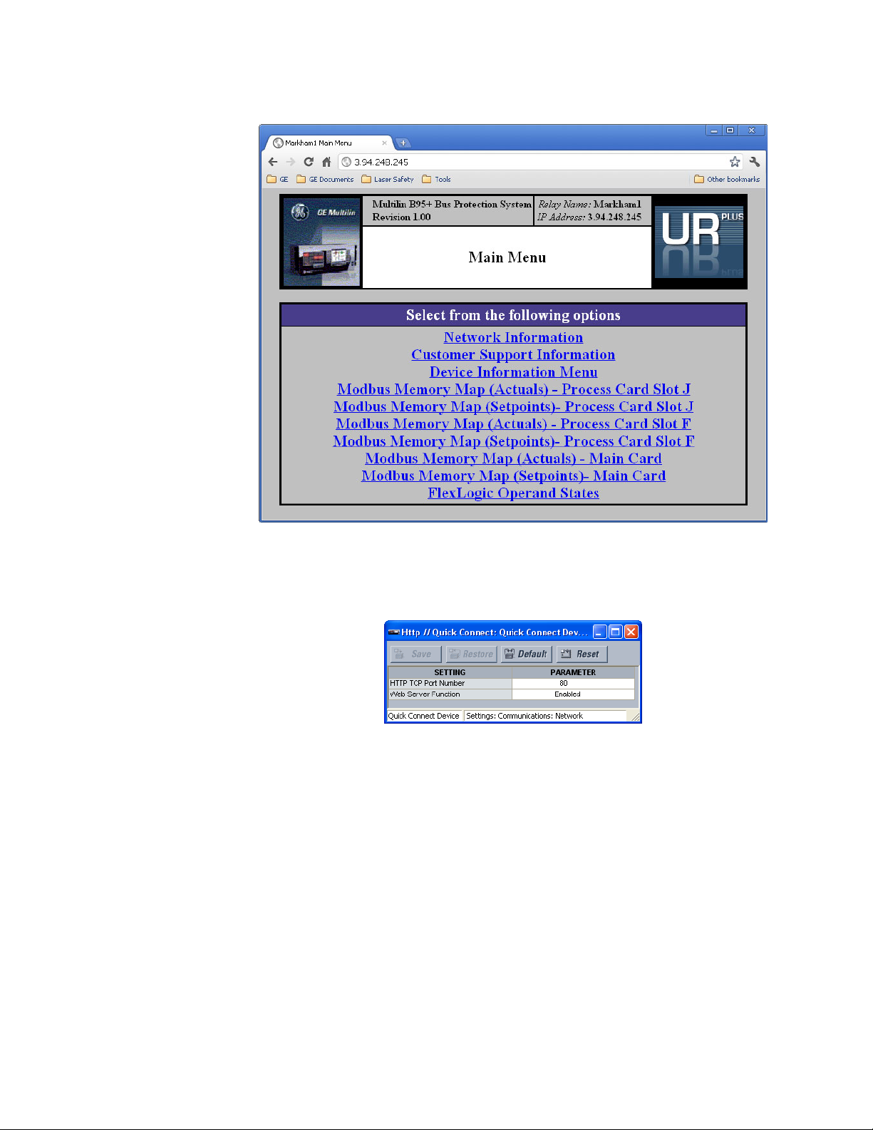
NETWORK SETTINGS CHAPTER 6: COMMUNICATIONS
Figure 4: Accessing a B95
Plus
device over the Internet (Chrome web browser)
To configure web browser access:
1. In the Online Window area of the software, navigate to Settings > Communications
> Network > HTTP to open the HTTP configuration window.
Figure 5: Enabling web access
The following settings are available.
HTTP TCP Port Number
Range: 1 to 65535 in steps of 1
Default: 80
This setting specifies the transmission control protocol (TCP) port number for the
embedded web server. This setting takes affect once the B95
Plus
is restarted.
Web Server Function
Range: Disabled, Enabled
Default: Disabled
This setting enables and disables the web server feature and web browser access of the
device.
66 MULTILIN B95
Plus
BUS PROTECTION SYSTEM – INSTRUCTION MANUAL
Page 77

CHAPTER 6: COMMUNICATIONS NETWORK SETTINGS
Viewing Ethernet actual values
Information about the Ethernet ports, speed, and status is viewable.
To view information about the Ethernet ports:
1. In the Online Window area of the software, navigate to Actual Values >
Communications > Communication to open the communications actual values
window.
Figure 6: Ethernet actual values
The following information displays.
Port 1, Port 2, Port 3 Ethernet Actual Mode
Range: 10/100 BASE-TX, 100 BASE-FX
Indicates the Ethernet hardware type on each of the three ports.
Port 1, Port 2, Port 3 Ethernet Duplex
Range: Full Duplex, Half Duplex
Indicates the Ethernet duplex mode on each of the three ports.
Port 1, Port 2, Port 3 Ethernet Speed
Range: 10 Mbps, 100 Mbps
Indicates the network speed on each of the three Ethernet ports.
Port 1, Port 2, Port 3 Ethernet Link Status
Range: Online, Offline
indicates the connection status of each of the three Ethernet ports.
IEC 60870-5-104 Available
Range: No, Yes
Indicates if the IEC 60870-5-104 protocol is enabled on the Ethernet ports.
IEC 61850 Available
Range: No, Yes
Indicates if the IEC 61850 protocol is enabled on the Ethernet ports.
MULTILIN B95
Plus
BUS PROTECTION SYSTEM – INSTRUCTION MANUAL 67
Page 78

NETWORK SETTINGS CHAPTER 6: COMMUNICATIONS
Configure IP Network Status
Range: OK, PORT 1 NETMASK ERROR, PORT 2 NETMASK ERROR, PORT 3 NETMASK
ERROR, PORT 1 IP ADDR RSVD, PORT 2 IP ADDR RSVD, PORT 3 IP ADDR RSVD, PORT 1 IP
ADDR LPBK, PORT 2 IP ADDR LPBK, PORT 3 IP ADDR LPBK, PORT 1 IP ADDR NETWK,
PORT 2 IP ADDR NETWK, PORT 3 IP ADDR NETWK, PRT 1-2 SUBNET OVRLP, PRT 1-3
SUBNET OVRLP, PRT 2-3 SUBNET OVRLP, > 1 GATEWAY DEFINED
Indicates the validity of the IP parameters applied to the network stack. See Ethernet
on
page 59.
Viewing TCP/IP connection actual values
The numbers of connections available are viewable..
To view connections remaining information:
1. In the Online Window area of the software, navigate to Actual Values >
Communications > Remaining Connection to open the remaining TCP/IP
connections actual values window.
Figure 7: Remaining TCP/IP connections
The following actual values display.
MMS Available TCP/IP Connections
Range: 0, 1, 2, 3, 4, 5
Indicates the number of connections available for IEC 61850 manufacturing message
specification (MMS) communications.
Modbus Available TCP/IP Connections
Range: 0, 1, 2, 3, 4
Indicates the number of connections available for Modbus communications.
DNP Available TCP/IP Connections
Range: 0, 1, 2
Indicates the number of connections available for distributed network protocol (DNP)
communications. The number of DNP connections is zero unless the “Network - TCP”
value has been selected for both the DNP Channel 1 Port and DNP Channel 2 Port
settings.
IEC Available TCP/IP Connections
Range: 0, 1, 2
Indicates the number of connections available for IEC 60870-5-104 communications.
68 MULTILIN B95
Plus
BUS PROTECTION SYSTEM – INSTRUCTION MANUAL
Page 79

CHAPTER 6: COMMUNICATIONS MODBUS COMMUNICATIONS
Modbus communications
The B95
communications protocol developed by a company called Modicon. The supported
commands allow a Modbus master device to monitor, program, and control the B95
Modbus is typically available via a RS-485 serial link (Modbus RTU) or via Ethernet (Modbus/
TCP). The B95
The B95
Plus
supports a subset of the Modicon Modbus protocol. Modbus is a serial
Plus
supports Modbus using Ethernet only.
Plus
always acts as a slave device, meaning that it never initiates communications;
Plus
.
it listens and responds to requests issued by a master device.
If you intend to use Modbus, configure the B95
Plus
for it using the following sections.
Otherwise, skip this section.
Modbus addresses are listed in the embedded web server. See the HTTP section in the
Communications chapter for information on this web server feature.
The Actuals memory mapped registers are accessed using the Modbus Input Registers
function codes. The Settings memory mapped registers are accessed using the Modbus
Holding Registers function codes. The main card slave address is 1, process card F slave
address is 3, and process card J slave address is 6.
Figure 8: Viewing the memory map in a web browser
MULTILIN B95
Protocol
In the B95
The server is capable of reporting any indication or measurement and operating any
virtual input. A user-configurable input and output map is also implemented.
The B95
To configure Modbus:
1. In the Online Window area of the software, navigate to Settings > Communications
Plus
BUS PROTECTION SYSTEM – INSTRUCTION MANUAL 69
Plus
, the Modbus server can simultaneously support four clients over Ethernet.
Plus
operates as a Modbus slave device.
> Modbus > Protocol to open the Modbus protocol configuration window.
Page 80

MODBUS COMMUNICATIONS CHAPTER 6: COMMUNICATIONS
Figure 9: Modbus protocol configuration settings
The following settings are available.
Modbus Slave Address
Range: 1
Default: 1
Plus
The base Modbus slave address for the B95
is fixed at 1. Different Modbus devices
are distinguished by their IP address.
Modbus TCP Port Number
Range: 1 to 65535 in steps of 1
Default: 502
This setting specifies the Modbus TCP port number for Ethernet communications. Any
change to this setting takes effect when power to the B95
Plus
is cycled.
User map
The Modbus user map provides access of up to 256 registers. Accessing a contiguous
block of registers via Modbus is faster than accessing the same number of individual
registers. To obtain a memory map value, enter the required address in the
Parameter
field (this value must be in decimal format), the Modbus Type and Card. The corresponding
value (if programmed) is displayed in the value field. A value of “0” in subsequent register
address lines automatically returns values for the previous address lines incremented by 1.
An address value of “0” in the initial register means none and values of “0” is displayed for
all registers. Different address values can be entered as required in any of the register
positions.
To view or change Modbus register values:
1. In the Online Window area of the software, navigate to Settings > Communications
> Modbus > User Map menu item to open the Modbus user map configuration
window.
2. To add a B95
Plus
register to the user map, for one of the user map addresses,
complete the required register's card, address and address. This information (in
hexadecimal) is listed on the relay's web page. The EnerVista software numeric setting
tool can accept hexadecimal values.
To read the user map using a third-party device supporting Modbus over TCP/IP:
1. On the third-party device, set the TCP port number to the value of the Settings >
Communications > Modbus > Protocol > Modbus TCP Port Number, which is also
listed as Modbus IP Port on the front panel annunciator display, Communications
Status page.
2. Set the IP address to the value of the Settings > Communications > Network >
Ethernet > Port x IP Address, where x is the number of the B95
Plus
port connected to.
3. Set the slave address as 1 (main card).
4. Set the function code to 4 (read Input Register).
5. Set the Address 0x1200 for user map starting at address 1, Address 0x1201 for user
map starting at address 2, and so on in sequence.
70 MULTILIN B95
Plus
BUS PROTECTION SYSTEM – INSTRUCTION MANUAL
Page 81

CHAPTER 6: COMMUNICATIONS DNP COMMUNICATIONS
Figure 10: Modbus user map configuration settings
The following Modbus user map settings are available for each of the 256 registers.
Card
Range: Main Card, Process Card F, Process Card J
Default: None
This setting selects the card originating the value mapped.
Modbus Type
Range: None, Settings, Actuals
Default: None
This setting selects the page originating the value mapped.
Parameter
Range: Modbus memory map address in decimal representation
Default: 0
This setting selects the Modbus address of the value mapped.
Value
Range: 0...65535
Default: 0
When the EnerVista software is online, this field indicates the actual value in decimal of
the Modbus register the Modbus user map address maps to, if any. This is not a setting.
MULTILIN B95
DNP communications
The distributed network protocol (DNP) allows for the optimization of control and data
acquisition between the equipment in the substation and the central control center. The
protocol is scalable; that is, it is compatible with the latest high speed local area network
(LAN) technology and can still be implemented over slower speed serial links. DNP
improves upon many master-slave protocols by improving overall communication
performance requirements and providing time-stamping with millisecond accuracy.
If ordered, either the DNP or IEC 60870-5-104 option is included, not both.
If you intend to use DNP, configure the B95
skip this section.
Plus
BUS PROTECTION SYSTEM – INSTRUCTION MANUAL 71
Plus
for it using the following sections. Otherwise,
Page 82

DNP COMMUNICATIONS CHAPTER 6: COMMUNICATIONS
NOTE
Protocol
The DNP server can simultaneously support one client over Ethernet or two clients over
Ethernet. Level 3 is supported for parsing requests and generating responses. It is capable
of reporting any indication or measurement and operating any output present in the
device. Both direct-operate and select-before-operate modes of control are supported.
Two user-configurable input and output maps are implemented.
To configure DNP:
1. In the Online Window area of the software, navigate to Settings > Communications
> DNP > Protocol to open the DNP protocol configuration window.
Figure 11: DNP configuration settings
The following settings are available.
NOTE:
Changes to the these settings take effect after power is cycled to the B95
DNP Channel 1 Port, DNP Channel 2 Port
Range: None, Network-TCP, Network-UDP
Default: None
These settings specify the communications port assigned to DNP for each channel. Once
DNP is assigned to a serial port, the Modbus protocol is disabled on that port. When this
setting is set to “Network-TCP,” DNP can be used over TCP/IP on channels 1 or 2. When
this value is set to “Network - UDP,” DNP can be used over UDP/IP on channel 1 only.
Changes to the these settings take effect after power is cycled to the B95
72 MULTILIN B95
Plus
.
Plus
.
Plus
BUS PROTECTION SYSTEM – INSTRUCTION MANUAL
Page 83

CHAPTER 6: COMMUNICATIONS DNP COMMUNICATIONS
DNP Channel Address
Range: 0 to 65519 in steps of 1
Default: 1
Plus
This setting specifies the DNP slave address. This number identifies the B95
on a DNP
communications link. Assign each DNP slave a unique address.
DNP Client Address 1...DNP Client Address 5
Range: any standard IP address
Default: 0.0.0.0
Plus
These settings force the B95
to respond to a maximum of five specific DNP masters.
DNP TCP/UDP Port Number
Range: 1 to 65535 in steps of 1
Default: 20000
This setting specifies the TCP/UDP port used for DNP communications.
DNP Unsolicited Response Function
Range: Enabled, Disabled
Default: Disabled
Change this setting to “Enabled” to activate the function.
DNP Unsolicited Response Timeout
Range: 0 to 60 seconds in steps of 1
Default: 5 seconds
Plus
This setting specifies how long the B95
waits for a DNP master to confirm an
unsolicited response.
DNP Unsolicited Response Maximum Re-Tries
Range: 1 to 255 in steps of 1
Default: 10
Plus
This setting specifies the number of times the B95
retransmits an unsolicited
response without receiving confirmation from the master. A value of “255” allows infinite
re-tries.
DNP Unsolicited Response Destination Address
Range: 0 to 65519 in steps of 1
Default: 1
This setting specifies the DNP address to which all unsolicited responses are sent. The IP
address to which unsolicited responses are sent is determined by the B95
Plus
from the
current TCP connection or the most recent UDP message.
DNP Current Scale Factor, DNP Voltage Scale Factor, DNP Other Scale Factor
Range: 0.001, 0.01. 0.1, 1, 10, 100, 1000, 10000, 100000
Default: 1
These settings scale the analog input current values. For example, if the DNP Current
Scale Factor is “10,” all DNP analog input points that represent currents are returned
with values 10 times smaller (for example, a value of 700 amps on the B95
Plus
is returned
as 70). Likewise, if the DNP Voltage Scale Factor is “0.01,” all DNP analog input points
that represent voltages are returned with values 100 times larger (for example, a value
of 17 volts on the B95
Plus
are returned as 1700).
These settings are useful when analog input values must be adjusted to fit within certain
ranges in DNP masters.
MULTILIN B95
Plus
BUS PROTECTION SYSTEM – INSTRUCTION MANUAL 73
Page 84

DNP COMMUNICATIONS CHAPTER 6: COMMUNICATIONS
DNP Current Default Deadband, DNP Voltage Default Deadband, DNP Other Default
Deadband
Range: 0 to 100000000 in steps of 1
Default: 30000
These settings determine when to trigger unsolicited responses containing analog Input
data. These settings group the B95
Plus
analog input data into the following types:
current; voltage; and other. Each setting represents the default deadband value for all
analog input points of that type. For example, to trigger unsolicited responses from the
Plus
when any current values change by 15 amps, set the DNP Current Default
B95
Deadband setting to “15.”
These settings are the deadband default values. DNP object 34 points can be used to
change deadband values from the default for each individual DNP analog input point.
Whenever power is removed and re-applied to the B95
Plus
, the default deadbands are in
effect.
DNP Time Sync IIN Period
Range: 1 to 10080 minutes in steps of 1
Default: 1440 minutes
This setting determines how often the Need Time Internal Indication (IIN) bit is set by the
Plus
. Changing this time allows the DNP master to send time synchronization
B95
commands more or less often, as required.
DNP Message Fragment Size
Range: 30 to 2048 in steps of 1
Default: 240
This setting determines the size, in bytes, at which message fragmentation occurs. Large
fragment sizes allow for faster and more efficient throughput; smaller fragment sizes
cause more application layer confirmations to be necessary, which can provide for more
robust data transfer over noisy communication channels.
DNP Object 1 Default Variation, DNP Object 2 Default Variation, DNP Object 20 Default
Variation, DNP Object 21 Default Variation, DNP Object 22 Default Variation, DNP
Object 23 Default Variation, DNP Object 30 Default Variation, DNP Object 32 Default
Variation
Range: 1, 2 (object 1); 1, 2, 3 (object 2), 1, 2, 5, 6 (objects 20, 22, and 23); 1, 2, 9, 10 (object
21); 1, 2, 3, 4, 5 (object 30); 1, 2, 3, 4, 5, 7 (object 32)
Default 1 (objects 20, 21, 22, 23, 30, and 32); 2 (objects 1 and 2)
These settings allow the user to select the DNP default variation number for object types
1, 2, 20, 21, 22, 23, 30, and 32. The default variation refers to the variation response when
variation 0 is requested or in class 0, 1, 2, or 3 scans.
DNP Number of Paired Controls
Range: 0 to 32 in steps of 1
Default: 0
The DNP binary outputs typically map one-to-one to IED data points. That is, each DNP
binary output controls a single physical or virtual control point in an IED. In the B95
Plus
,
DNP binary outputs are mapped to virtual inputs. However, some legacy DNP
implementations use a mapping of one DNP binary output to two physical or virtual
control points to support the concept of trip and close (for circuit breakers) or raise and
lower (for tap changers) using a single control point. That is, the DNP master can operate
a single point for both trip and close, or raise and lower, operations. The B95
Plus
can be
configured to support paired control points, with each paired control point operating
two virtual inputs. This setting allows configuration of from 0 to 32 binary output paired
controls. Points not configured as paired operate on a one-to-one basis.
74 MULTILIN B95
Plus
BUS PROTECTION SYSTEM – INSTRUCTION MANUAL
Page 85

CHAPTER 6: COMMUNICATIONS DNP COMMUNICATIONS
DNP TCP Connection Timeout
Range: 10 to 300 seconds in steps of 1
Default: 120 seconds
This setting specifies a time delay for the detection of dead network TCP connections.
When there is no data traffic on a DNP TCP connection beyond the time specified by this
setting, the connection is aborted by the B95
Plus
. This frees up the connection to be re-
used by a client.
User point list
The binary and analog inputs points for the DNP protocol can configured to a maximum of
256 points. The value for each point is user-programmable and can be configured by
assigning FlexLogic
inputs.
The DNP point lists always begin with point 0 and end at the first “Off” value. Since DNP
point lists must be in one continuous block, any points assigned after the first “Off” point
are ignored. Changes to the DNP point lists take effect when the B95
To configure DNP input points:
1. In the Online Window area of the software, navigate to Settings > Communications
> DNP > User Point List to open the DNP user point list configuration window.
operands for binary inputs or FlexAnalog™ parameters for analog
Plus
is restarted.
Figure 12: DNP user point list configuration settings
The following settings are available for points 0 through 255.
Binary Input Point 0...Binary Input Point 255
Range: any FlexLogic™ operand
Default: Off
These settings represent DNP binary input points and are configured by assigning an
appropriate FlexLogic
operand. Up to 256 binary input points can be configured for DNP.
Analog Input Point 0...Analog Input Point 255
Range: any FlexAnalog™ parameter
Default: Off
These settings represent DNP analog input points and are configured by assigning an
appropriate FlexAnalog™ parameter. Up to 256 analog input points can be configured
for DNP.
MULTILIN B95
Plus
BUS PROTECTION SYSTEM – INSTRUCTION MANUAL 75
Page 86

IEC 60870-5-104 COMMUNICATIONS CHAPTER 6: COMMUNICATIONS
IEC 60870-5-104 communications
IEC 60870-5-104 is a standard for communication between a control station and
substation using TCP/IP. The IEC 60870-5-104 server supports two clients simultaneously. It
is capable of reporting any indication or measurement and operating any output present
in the device. These point lists are shared with DNP.
To use it, you specify the client and power thresholds. The B95
device, such as a computer or a gateway, is the client, and it can be in the substation or
elsewhere.
If ordered, either the DNP or IEC 60870-5-104 option is included, not both.
Configuring IEC 60870-5-104 settings
Specify the client, such as a computer or gateway, and thresholds to use the protocol.
To configure the IEC 60870-5-104 settings:
1. In the Online Window area of the software, navigate to Settings > Communications
> IEC 60870-5-104 > Protocol to open the configuration window. When the option
does not display, it means that it was not ordered.
Plus
is not the client. Another
Figure 13: IEC 60870-5-104 protocol configuration settings
The following settings are available.
IEC TCP Port Number
Range: 0 to 65535 in steps of 1
Default: 2404
This setting specifies the TCP port number to use for IEC 60870-5-104 communications.
IEC Client Address 1...IEC Client Address 5
Range: standard IP address format
Default: 0.0.0.0
These settings specify the IP addresses for five IEC 60870-5-104 clients. The B95
not a client. Examples of clients are a computer and a gateway, either in the substation
or elsewhere.
Plus
is
76 MULTILIN B95
Plus
BUS PROTECTION SYSTEM – INSTRUCTION MANUAL
Page 87

CHAPTER 6: COMMUNICATIONS IEC 60870-5-104 COMMUNICATIONS
IEC Common Address of ASDU
Range: 0 to 65535 in steps of 1
Default: 0
Plus
This setting specifies the local address of the B95
for IEC 60870-5-104 transactions.
The address is common to all data in a single application service data unit (ASDU). The
combination of ASDU common address and information object address (IOA) uniquely
identifies each data item in a system.
IEC Cyclic Data Period
Range: 1 to 65535 seconds in steps of 1
Default: 60 seconds
Plus
This setting specifies the rate at which the B95
sends updated point data regardless
of whether or not a status change has occurred. This data includes binary inputs, binary
outputs, and analog inputs.
IEC Current Default Threshold, IEC Voltage Default Threshold, IEC Power Default
Threshold, IEC Power Factor Default Threshold, IEC Other Default Threshold
Range: 0 to 100000000 in steps of 1
Default: 30000
These settings are used to determine when to trigger spontaneous responses containing
M_ME_NC_1 analog data. These settings group the B95
Plus
analog data into types:
current, voltage, power, energy, and other. Each setting represents the default threshold
value for all M_ME_NC_1 analog points of that type. For example, to trigger spontaneous
responses from the B95
Plus
when any current values change by 15 amps, set the IEC
Current Default Threshold setting to “15.” Note that these settings are the default
values of the deadbands. P_ME_NC_1 (parameter of measured value, short floating
point value) points can be used to change threshold values, from the default, for each
individual M_ME_NC_1 analog point. The default thresholds take effect when power is
cycled to the B95
Plus
(turned off then on).
Configuring IEC 60870-5-104 point lists
The monitored single point (MSP) and monitored measured data (MME) points for the IEC
60870-5-104 protocol can be configured to a maximum of 256 points. The MME points are
analog. The value for each point is user-programmable and can be configured by
assigning FlexLogic
MME points.
The IEC 60870-5-104 point lists always begin with point 0 and end at the first “Off” value.
Because an IEC 60870-5-104 point list must be one continuous block, any points assigned
after the first “Off” point are ignored.
To configure the point lists:
1. In the Online Window area of the software, navigate to Settings > Communications
> IEC 60870-5-104 > User Point List to open the IEC 60870-5-104 user point list
configuration window. When the option does not display, it means that it was not
ordered.
The following settings are available.
Changes to the lists take effect when the B95
operands for binary MSP points or FlexLogic parameters for analog
Plus
is restarted.
MULTILIN B95
Plus
BUS PROTECTION SYSTEM – INSTRUCTION MANUAL 77
Page 88

IEC 61850 COMMUNICATIONS CHAPTER 6: COMMUNICATIONS
Binary Input Point 0...Binary Input Point 255
Range: any FlexLogic operand
Default: Off
These settings represent the IEC 60870-5-104 binary MSP points and are configured by
assigning an appropriate FlexLogic
operand. Up to 256 MSP points can be configured for
the IEC 60870-5-104 protocol.
Analog Input Point 0...Analog Input Point 255
Range: any FlexAnalog parameter
Default: Off
These settings represent the IEC 60870-5-104 analog MME points and are configured by
assigning an appropriate FlexLogic
parameter. Up to 256 MME points can be configured
for the IEC 60870-5-104 protocol.
IEC 61850 communications
Ethernet ports 2 and 3 on the communications card in slot C support the manufacturing
message specification (MMS) protocol as specified by IEC 61850. MMS is supported over
the TCP/IP-over-Ethernet protocol stack. Polling, unbuffered reporting, and buffered
reporting are supported. In addition, these ports support GSSE/GOOSE. The process card
ports intended for communication with Bricks support sampled values.
Remote inputs and outputs provide a way to exchange digital state information between
Ethernet-connected devices. The GSSE and GOOSE standards are used for this purpose.
GSSE/GOOSE configuration
IEC 61850 provides the following two fast mechanisms to exchange information between
relays in a substation at rapid speeds for performing interlocking and other time-critical
substation functions:
• GSSE — Generic Substation Status Event — Used for transferring status information
only
• GOOSE — Generic Object-Oriented Substation Event — Supports a variety of information types, including measured values
The B95Plus supports GSSE and two variants of GOOSE: the so-called Fixed GOOSE and
configurable GOOSE.
The sharing of digital point state information between GSSE/GOOSE equipped relays is
essentially an extension to FlexLogic, allowing for distributed FlexLogic
operands available to and from devices on a common communications network. The
publisher (relays that source the data) packages the values of user selected FlexLogic
or FlexAnalog operands in an Ethernet frame according to the GSSE/GOOSE protocol, using
a multi-cast destination address. The network sends each multi-cast frame to all or to a
configured subset of all the relays in the substation. Subscribers (relays that listen to the
data) set other FlexLogic
received frames according to their configuration settings.
FlexLogic operands selected for transmission are scanned eight times per power system
cycle; whenever a change of state is observed, the containing GSSE/GOOSE frame is
immediately transmitted with the new state value. FlexAnalogs selected for transmission
are also scanned but at a lower rate; whenever a value is observed that is outside its
configured bandwidth, the containing GSSE/GOOSE frame is immediately transmitted with
the new value. The bandwidth is initially 10%, but can be changed using the IEC 61850
and/or FlexAnalog operands from the specific values in the
by making
and/
78 MULTILIN B95
Plus
BUS PROTECTION SYSTEM – INSTRUCTION MANUAL
Page 89

CHAPTER 6: COMMUNICATIONS IEC 61850 COMMUNICATIONS
SetDataValues service. (The deadband extends to either side of the last reported value by
the set percentage of 46 times the base current for current quantities, or by the set
percentage of 275 times the voltage ratio setting for voltage quantities.)
To guard against loss of a change of state frame in the network, after the initial frame, the
frame is repeated. GSSE and Fixed GOOSE frames are resent 16, 32, 64, 128, and 256
ms
following the initial change of state frame. Configurable GOOSE frames are resent
according to the Retransmission Profile setting. To allow subscribers to detect loss of
communications and publisher offline, when no change of state has occurred, the frame is
resent at the rate of the Default GSSE/GOOSE Update Time setting. Publishers include in
the frame a time-to-live value, which indicates to the subscribers the time to wait for
another frame before declaring the connection failed.
In dual-IP redundant configurations, the IED transmits and listens on both ports
simultaneously.
Remote inputs and outputs provide a way to exchange digital state information between
Ethernet-connected devices. The GSSE and GOOSE standards are used for this purpose.
The sharing of digital point state information between GSSE/GOOSE equipped relays is
essentially an extension of FlexLogic, allowing for distributed FlexLogic
by making
operands available to and from devices on a common communications network. In
addition to digital point states, GSSE/GOOSE messages identify the originator of the
message and provide information required by the communication specification. All devices
listen to network messages and capture data only from messages that have originated in
selected devices.
IEC 61850 GSSE messages are compatible with UCA GOOSE messages and contain a fixed
set of digital points. IEC 61850 GOOSE messages can, in general, contain any configurable
data items.
Both GSSE and GOOSE messages are designed to be short, reliable, and have high priority.
GOOSE messages have additional advantages over GSSE messages due to their support of
VLAN (virtual LAN) and Ethernet priority tagging functionality.
The GSSE message structure contains space for 160 bit-pairs representing digital point
state information. The IEC 61850 specification provides 32 DNA bit-pairs that represent the
state of two pre-defined events and 30 user-defined events. All remaining bit-pairs are
UserSt bit-pairs, which are status bits representing user-definable events. The
B95
Plus
implementation provides access to the first 32 UserSt bit-pairs. The B95
Plus
also
supports a so-called “Fixed GOOSE” service, wherein the data set consists of 32 DNA
members and 32 UserSt members. Each member contains the same information as a bitpair.
The IEC 61850 specification includes features that are used to cope with the loss of
communication between transmitting and receiving devices. Each transmitting device
sends a GSSE/GOOSE message on power-up, when the state of any included point
changes, or after a specified interval (the default update time) if a change-of-state has not
occurred. The transmitting device also sends a hold time that is the GSSE equivalent of
time-to-live (TTL) in IEC GOOSE messages.
Receiving devices constantly monitor the communications network for messages they
require, as recognized by the identification of the originating device carried in the
message. Messages received from remote devices include the message TTL allowed. The
receiving relay sets a timer assigned to the originating device to this time interval, and if it
has not received another message from this device at time-out, the remote device is
declared to be non-communicating, so it uses the programmed default state for all points
from that specific remote device. If a message is received from a remote device before the
TTL expires, all points for that device are updated to the states contained in the message
and the hold timer is restarted. The status of a remote device, where “Offline” indicates
non-communicating, can be displayed.
MULTILIN B95
Plus
BUS PROTECTION SYSTEM – INSTRUCTION MANUAL 79
Page 90
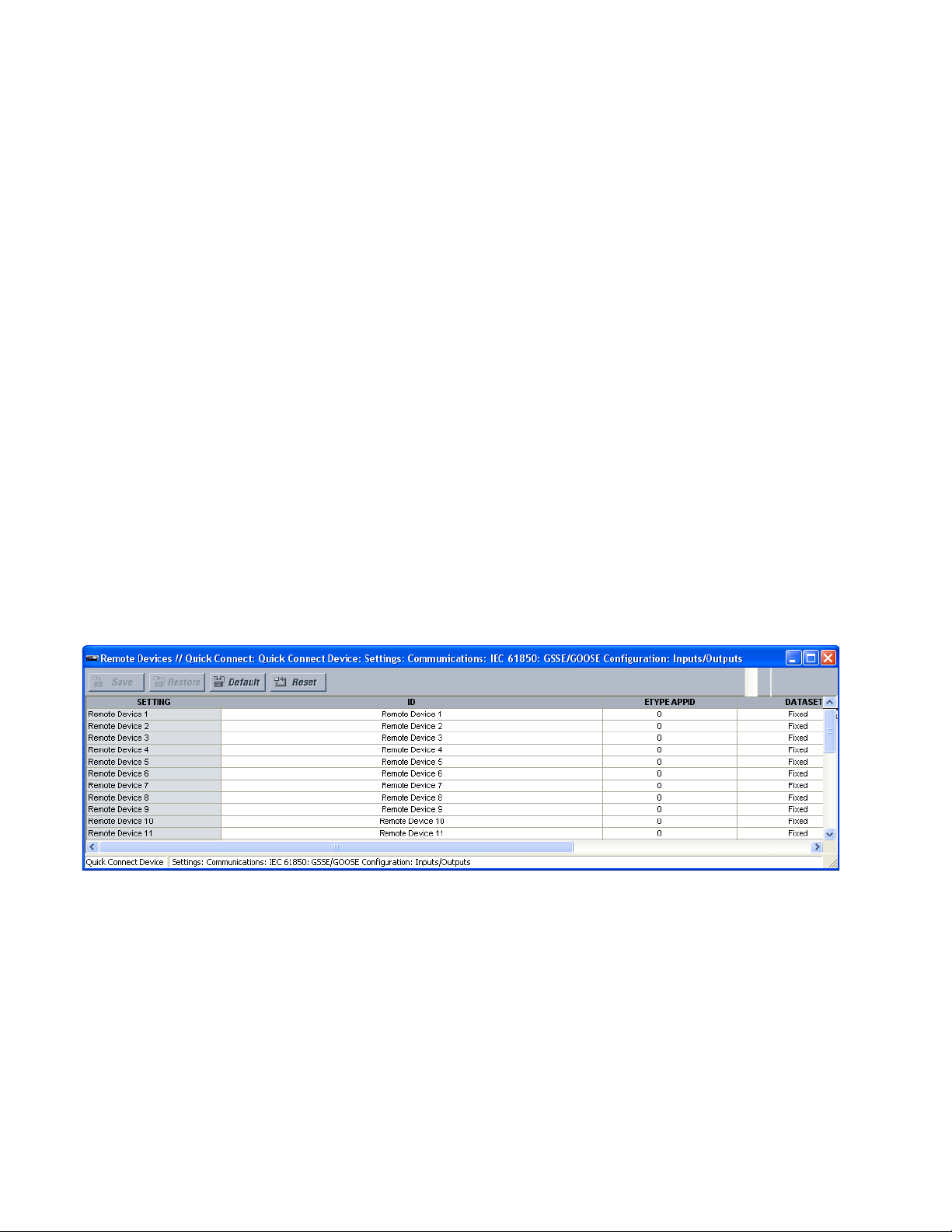
IEC 61850 COMMUNICATIONS CHAPTER 6: COMMUNICATIONS
The B95
In a UR
programmed in the
Plus
provides for 64 remote inputs and 64 remote outputs.
Plus
-series IED, the device ID that identifies the originator of the message is
IED Name setting.
Traditionally hardwired digital inputs and outputs were used to exchange signals between
relays. The IEC 61850 peer-to-peer messaging service is designed to replace this
traditional signaling technique with messaging over Ethernet. Within the UR
Plus
B95
family, the function of the contact inputs and outputs for signaling are, in effect,
Plus
and
replaced by remote inputs and remote outputs.
The B95
Plus
has an additional class of transmission called fixed GOOSE, which is really the
standard GOOSE transmission restricted to digital values The user can configure up to
eight GOOSE data transmissions and 40 receptions and are collectively referred to as the
configurable GOOSE withinB95
Plus
documentation. The relay supports an additional
transmission and reception using Fixed GOOSE or GSSE. All GOOSE transmissions support
64 items within the data set, a unique name, VLAN ID, and priority and work as
independently transmission/reception entities within the relay. The data that can be
configured for transmission within each of the eight transmissions can be a combination
of digital and analog points. A digital status change or an analog point exceeding its deadband setting will cause the associated data set to be transmitted within 1
msec of the
event.
Use of GSSE or GOOSE needs to be enabled for the device, as outlined in this and
subsequent sections.
To configure communication to remote devices:
1. In the Online Window area of the software, navigate to Settings > Communications
> IEC 61850 > GSSE/GOOSE Configuration > Inputs/Outputs > Remote Devices to
open the remote devices configuration window.
Figure 14: Remote devices configuration settings
The following settings are available for each of the 32 remote devices.
ID
Range: up to 65 characters
Default: Remote Device n
Up to 32 remote devices can be selected for settings purposes. A receiving relay must be
programmed to capture messages from only those originating remote devices of
interest. This setting is used to select specific remote devices by entering an exact
identification (ID) assigned to those devices.
80 MULTILIN B95
Plus
BUS PROTECTION SYSTEM – INSTRUCTION MANUAL
Page 91

CHAPTER 6: COMMUNICATIONS IEC 61850 COMMUNICATIONS
ETYPE APPID
Range: 0 to 16383 in steps of 1
Default: 0
This setting is used with GOOSE messages; it does not apply to GSSE messages. This
setting identifies the application identification in the GOOSE message. It needs to match
the corresponding settings on the sending device.
DATASET
Range: Fixed, GOOSE 1 through GOOSE 8
Default: Fixed
Plus
This setting provides for the choice of the UR
-series fixed (DNA/UserSt) dataset (that
is, containing DNA and UserSt bit-pairs), or one of the configurable datasets.
The dataset for the received data items must be made up of existing items in an existing
logical node. For this reason, logical node GGIO3 is instantiated to hold the incoming
data items. GGIO3 is not necessary to make use of the received data. The remote input
data item mapping takes care of the mapping of the inputs to remote input
FlexLogic
operands. However, GGIO3 data can be read by IEC 61850 clients.
Transmission To change the default GSSE/GOOSE update time:
1. In the Online Window area of the software, navigate to Settings > Communications
> IEC 61850 > GSSE/GOOSE Configuration > Transmission > General to open the
GSSE/GOOSE general transmission configuration window.
Figure 15: General transmission configuration settings
The following setting is available.
Default GSSE/GOOSE Update Time
Range: 1 to 60 seconds
Default: 60 seconds
This setting specifies the time between GSSE or GOOSE messages when there are no
remote output state changes to be sent. When remote output data changes, GSSE or
GOOSE messages are sent immediately. This setting controls the steady-state heartbeat
time interval.
Plus
This setting applies to GSSE, B95
Fixed GOOSE, and configurable GOOSE.
GSSE To configure the unit to transmit information using the GSSE protocol:
1. In the Online Window area of the software, navigate to Settings > Communications
> IEC 61850 > GSSE/GOOSE Configuration > Transmission > GSSE to open the GSSE
transmission configuration window.
MULTILIN B95
Plus
BUS PROTECTION SYSTEM – INSTRUCTION MANUAL 81
Page 92

IEC 61850 COMMUNICATIONS CHAPTER 6: COMMUNICATIONS
Figure 16: GSSE transmission configuration settings
The following settings are available.
Function
Range: Enabled, Disabled
Default: Disabled
This setting enables and disables the GSSE transmission functionality.
ID
Range: up to 65 ASCII characters
Default: GSSEOut
This setting represents the IEC 61850 GSSE name string sent as part of each GSSE
message. This name string identifies the GSSE message to the receiving device, so that
the receiving device can distinguish it from GSSE messages from other devices. This
setting is required by IEC 61850 to be unique within the substation.
Destination MAC
Range: standard MAC address format
Default: 00 00 00 00 00 00
This setting specifies the destination Ethernet MAC address for the GSSE transmission.
Make this address a multicast address and set the least significant bit of the first byte.
If this setting is specified as “00 00 00 00 00 00” (the default value), then a multicast MAC
address is formed based on the MAC address of Ethernet ports 2 and 3. To view the MAC
address of the B95
Plus
at hand, page down the annunciator panel to the
Communications Status page, or navigate in the software to Actual Values > Product
Information > Model Information.
GSSE Minimum Hold Time
Range: 50 to 4000 ms in steps of 1
Default: 400 ms
This setting specifies the minimum hold time for GSSE data. This refers to the lifespan of
the data, after which the subscribers consider it old data.
Fixed GOOSE To configure the unit to transmit information using the fixed GOOSE protocol:
1. In the Online Window area of the software, navigate to Settings > Communications
> IEC 61850 > GSSE/GOOSE Configuration > Transmission > Fixed GOOSE to open
the fixed GOOSE transmission configuration window.
82 MULTILIN B95
Plus
BUS PROTECTION SYSTEM – INSTRUCTION MANUAL
Page 93

CHAPTER 6: COMMUNICATIONS IEC 61850 COMMUNICATIONS
Figure 17: Fixed GOOSE transmission configuration settings
The following settings are available.
Function
Range: Enabled, Disabled
Default: Disabled
This setting enables and disables the fixed GOOSE transmission functionality.
ID
Range: up to 65 ASCII characters
Default: GOOSEOut
This setting represents the IEC 61850 GOOSE ID (GoID) name string sent as part of each
GOOSE message. This name string identifies the GOOSE message to the receiving device,
so that the receiving device can distinguish it from GOOSE messages from other devices.
This setting is required by IEC 61850 to be unique within the substation.
Destination MAC
Range: standard MAC address format
Default: 00 00 00 00 00 00
This setting specifies the destination Ethernet MAC address for the fixed GOOSE
transmission. Make this address a multicast address, and set the least significant bit of
the first byte.
If this setting is specified as “00 00 00 00 00 00” (the default value), then a multicast MAC
address is formed based on the MAC address of Ethernet ports 2 and 3. To view the MAC
address of the B95
Plus
at hand, page down the annunciator panel to the
Communications Status page, or navigate in the software to Actual Values > Product
Information > Model Information.
GOOSE VLAN Priority
Range: 0 to 7 in steps of 1
Default: 4
This setting indicates the Ethernet priority of GOOSE messages. This allows GOOSE
messages to have higher priority than other Ethernet data. This setting is required by IEC
61850.
GOOSE VLAN ID
Range: 0 to 4096 in steps of 1
Default: 0
This setting allows the selection of a specific VLAN ID for each GOOSE sending device.
The value can be left at its default when the feature is not required.
MULTILIN B95
Plus
BUS PROTECTION SYSTEM – INSTRUCTION MANUAL 83
Page 94

IEC 61850 COMMUNICATIONS CHAPTER 6: COMMUNICATIONS
GOOSE ETYPE APPID
Range: 0 to 16383 in steps of 1
Default: 0
This setting allows the selection of a specific application ID for each GOOSE message.
The APPID is another way by which the receiving device can distinguish this GOOSE
message from other GOOSE messages. This setting is required by IEC 61850, to be
unique within the substation.
GOOSE Minimum Time to Live
Range: 50 to 4000 ms in steps of 1
Default: 400 ms
This setting specifies the minimum time to live value for the GOOSE transmission data
set. This refers to the lifespan of the data, after which the subscribers consider it old
data.
Tx Configurable
GOOSE
The configurable GOOSE settings allow the B95
Plus
to be configured to transmit a number
of IEC 61850 GOOSE messages, each with configurable datasets. Up to eight messages
can be configured and transmitted, allowing for the optimization of data transfer between
devices. This is useful for intercommunication between B95
Plus
IEDs and devices from
other manufacturers that support IEC 61850 GOOSE.
Items programmed for GOOSE messages 1 through 8 have changes in their values
checked for change once per protection pass for digital data and less often for analog
data. When a change is detected, a GOOSE message is transmitted immediately and
repeated several times as determined by the Retrans Profile setting. When no change is
detected, GOOSE messages are sent periodically at a rate determined by the Default GSSE/
GOOSE Update Time setting to allow subscribers to verify link integrity and to
communicate the values to subscribers that have just started up or have just had their
communications restored.
IEC 61850 GOOSE messages contain a number of configurable parameters, all of which
must be correct for successful data transfer. It is critical that the configured datasets at the
transmission and reception devices are an exact match in terms of data structure and that
the GOOSE addresses and name strings match exactly. Manual configuration is possible,
but third-party substation configuration software can be used to automate the process.
The EnerVista software can produce IEC 61850 ICD files and import IEC 61850 SCD files
produced by a substation configurator.
To configure the unit to transmit information using the GOOSE protocol:
1. In the Online Window area of the software, navigate to Settings > Communications
> IEC 61850 > GSSE/GOOSE Configuration > Transmission > Tx Configurable
GOOSE to open the configurable GOOSE transmission configuration window.
84 MULTILIN B95
Plus
BUS PROTECTION SYSTEM – INSTRUCTION MANUAL
Page 95

CHAPTER 6: COMMUNICATIONS IEC 61850 COMMUNICATIONS
Figure 18: Configurable GOOSE transmission configuration settings
The following settings are available for each of the eight configurable GOOSE messages.
GOOSEOut Function
Range: Enabled, Disabled
Default: Disabled
This setting enables and disabled the configurable GOOSE transmission functionality.
GOOSEOut ID
Range: up to 65 ASCII characters
Default: GOOSEOut_1
This setting represents the IEC 61850 GOOSE ID (GoID) name string sent as part of each
GOOSE message. This name string identifies the GOOSE message to the receiving device,
so that the receiving device can distinguish it from GOOSE messages from other devices.
This setting is required by IEC 61850 to be unique within the substation.
GOOSEOut Destination MAC
Range: standard MAC address format
Default: 00 00 00 00 00 00
This setting specifies the destination Ethernet MAC address for the configurable GOOSE
transmission. Make this address a multicast address, and set the least significant bit of
the first byte.
If this setting is specified as “00 00 00 00 00 00” (the default value), then a multicast MAC
address is formed based on the MAC address of Ethernet ports 2 and 3. To view the MAC
address of the B95
Plus
at hand, page down the annunciator panel to the
Communications Status page, or navigate in the software to Actual Values > Product
Information > Model Information.
GOOSEOut VLAN Priority
Range: 0 to 7 in steps of 1
Default: 4
This setting indicates the Ethernet priority of GOOSE messages. This allows GOOSE
messages to have higher priority than other Ethernet data. This setting is required by IEC
61850.
GOOSEOut VLAN ID
Range: 0 to 4096 in steps of 1
Default: 0
This setting allows the selection of a specific VLAN ID for each GOOSE sending device.
This value can be left at its default if the feature is not required.
MULTILIN B95
Plus
BUS PROTECTION SYSTEM – INSTRUCTION MANUAL 85
Page 96

IEC 61850 COMMUNICATIONS CHAPTER 6: COMMUNICATIONS
EGOOSEOut ETYPE APPID
Range: 0 to 16383 in steps of 1
Default: 0
This setting allows the selection of a specific application ID for each GOOSE sending
device. The APPID is another way by which the receiving device can distinguish this
GOOSE message from other GOOSE messages. This setting is required by IEC 61850, to
be unique within the substation.
GOOSEOut ConfRev
Range: 1 to 16383 in steps of 1
Default: 1
This setting determines the value sent in the GOOSE message’s ConfRev field whenever
a Dataset Item’s mapping is changed. This value increments automatically as described
in IEC 61850 part 7-2.
GOOSEOut Minimum Time to Live
Range: 50 to 4000 ms in steps of 1
Default: 400 ms
This setting specifies the minimum time to live (TTL) for the GOOSE transmission data.
This refers to the lifespan of the data, after which the subscribers consider it old data.
GOOSEOut Retransmission Profile
Range: None, Aggressive, Standard, Relaxed
Default: Standard
Plus
The B95
supports four retransmission schemes: aggressive; standard; relaxed; and
none. The “Aggressive” profile can be selected for trip schemes, the “Standard” profile for
remedial action schemes, the “Relaxed” profile for analogues, and “None” for schemes
that incorporate a separate confirmation scheme.
The following retransmission times are specified under these profiles:
– “Aggressive”: 4, 8, 16, 32, and 64 ms
– “Standard”: 16, 32, 64, 128, and 256 ms
– “Relaxed”: 100, 200, 400, 800, and 1000 ms
– “None”: no retransmission
For GSSE and fixed GOOSE, the profile is fixed at “Aggressive” and there is no associated
setting.
GOOSEOut Dataset Item 1, Dataset Item 2, Dataset Item 3,..., Dataset Item 64
Range: all IEC 61850 information model basic attributes supported for transmission
Default: 0
These settings are used to select an attribute for each configurable GOOSE dataset item,
that is, an IEC 61850 information model item that has a value.
To create a configurable GOOSE dataset that contains an IEC 61850 Single Point Status
indication and its associated quality flags, the following dataset items can be selected:
“GGIO1.ST.Ind1.stVal” and “GGIO1.ST.Ind1.q.” The B95
Plus
then creates a dataset
containing these two data items. The status value for GGIO1.ST.Ind1.stVal is determined
by the operand assigned to GGIO1 indication 1. Changes to this operand result in the
transmission of GOOSE messages containing the defined dataset.
86 MULTILIN B95
Plus
BUS PROTECTION SYSTEM – INSTRUCTION MANUAL
Page 97

CHAPTER 6: COMMUNICATIONS IEC 61850 COMMUNICATIONS
Rx Configurable
GOOSE
To configure the unit to receive data using the GOOSE protocol:
1. In the Online Window area of the software, navigate to Settings > Communications
> IEC 61850 > GSSE/GOOSE Configuration > Reception > Rx Configurable GOOSE to
open the configurable GOOSE reception configuration window.
Figure 19: Configurable GOOSE reception configuration settings
The following settings are available for each of the eight datasets for configurable GOOSE
reception.
Dataset Item 1...Dataset Item 64
Range: all IEC 61850 information model basic attributes supported for reception
Default: None
These settings are used to select an attribute for each configurable GOOSE dataset item.
Remote devices To configure communication to remote devices:
1. In the Online Window area of the software, navigate to Settings > Communications
> IEC 61850 > GSSE/GOOSE Configuration > Inputs/Outputs > Remote Devices to
open the remote devices configuration window.
Figure 20: Remote devices configuration settings
The following settings are available for each of the 32 remote devices.
ID
Range: up to 65 characters
Default: Remote Device n
Up to 32 remote devices can be selected for settings purposes. A receiving relay must be
programmed to capture messages from only those originating remote devices of
interest. This setting is used to select specific remote devices by entering an exact
identification (ID) assigned to those devices.
MULTILIN B95
Plus
BUS PROTECTION SYSTEM – INSTRUCTION MANUAL 87
Page 98
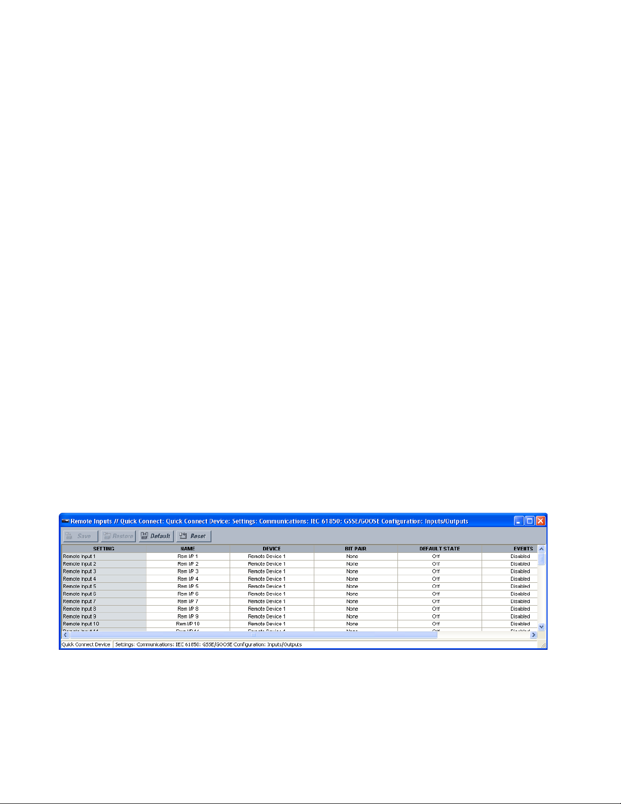
IEC 61850 COMMUNICATIONS CHAPTER 6: COMMUNICATIONS
ETYPE APPID
Range: 0 to 16383 in steps of 1
Default: 0
This setting is used with GOOSE messages; it does not apply to GSSE messages. This
setting identifies the application identification in the GOOSE message. It needs to match
the corresponding settings on the sending device.
DATASET
Range: Fixed, GOOSE 1 through GOOSE 8
Default: Fixed
Plus
This setting provides for the choice of the UR
-series fixed (DNA/UserSt) dataset (that
is, containing DNA and UserSt bit-pairs), or one of the configurable datasets.
The dataset for the received data items must be made up of existing items in an existing
logical node. For this reason, logical node GGIO3 is instantiated to hold the incoming
data items. GGIO3 is not necessary to make use of the received data. The remote input
data item mapping takes care of the mapping of the inputs to remote input
FlexLogic
operands. However, GGIO3 data can be read by IEC 61850 clients.
Remote inputs Remote inputs are FlexLogic
from GSSE/GOOSE messages originating in remote devices. The B95
remote inputs, each of which can be selected from a list consisting of 128 selections as
follows: DNA-1 through DNA-32; UserSt-1 through UserSt-32; and DatasetItem 1 through
64. The function of DNA end UserSt inputs is defined by the user selection of the
FlexLogic
The first two DNA items are reserved by IEC 61850 for “test” and “ConfRev” and are not to
be used for other purposes.
Remote input are programmed to replicate the logic state of a specific signal from a
specific remote device for local use. This programming is performed via the three settings
indicated as follows.
To configure the unit for use of remote inputs:
1. In the Online Area window of the software, navigate to Settings > Communications >
Figure 21: Remote inputs configuration settings
operand whose state is represented in the GSSE/GOOSE message.
IEC 61850 > GSSE/GOOSE Configuration > Inputs/Outputs > Remote Inputs to open
the remote inputs configuration window.
operands at the receiving relay whose values are extracted
Plus
provides 64
The following settings are available for each of the 32 remote inputs.
Name
Range: up to 12 characters
Default: Rem Ip n
This setting allows the user to assign descriptive text to the remote input.
88 MULTILIN B95
Plus
BUS PROTECTION SYSTEM – INSTRUCTION MANUAL
Page 99

CHAPTER 6: COMMUNICATIONS IEC 61850 COMMUNICATIONS
Device
Range: 1 to 32 inclusive
Default: Remote Device n
This setting selects the number (1 to 32) of the remote device that originates the required
signal, as previously assigned to the remote device via the Remote Device ID setting.
Bit Pair
Range: None, DNA-1 to DNA-32, UserSt-1 to UserSt-32, Dataset Item 1 to Dataset Item
64
Default: None
This setting selects the specific bit of the GSSE/GOOSE message required.
Default State
Range: On, Off, Latest/On, Latest/Off
Default: Off
This setting selects the logic state for this point if the local relay has just completed
startup or the remote device sending the data is declared to be non-communicating.
The following choices are available.
– The “On” value defaults the input to logic 1.
– The “Off” value defaults the input to logic 0.
– The “Latest/On” value freezes the input in case of lost communications. If the
latest state is not known, such as after relay power-up but before the first
communication exchange, the input defaults to logic 1. When communication
resumes, the input becomes fully operational.
– The “Latest/Off” value freezes the input in case of lost communications. If the
latest state is not known, such as after relay power-up but before the first
communication exchange, the input defaults to logic 0. When communication
resumes, the input becomes fully operational.
Events
Range: Enabled, Disabled
Default: Disabled
This setting enables and disables the logging of remote input status changes in the
event recorder.
Remote DPS inputs Remote double-point status (DPS) inputs are extracted from GOOSE messages originating
in the remote device. The B95
Plus
provides 16 remote double-point status inputs. Each
remote double-point status input must be programmed to replicate the logic state of a
specific signal from a specific remote device for local use.
The configurable GOOSE dataset items must be changed to accept a DPS item from a
GOOSE dataset. Dataset items configured to receive any of “GGIO3.ST.IndPos1.stVal” to
“GGIO3.ST.IndPos16.stVal” accept double-point status information that is decoded by the
remote DPS inputs configured to this dataset item.
To configure the unit for remote double-point status inputs:
1. In the Online Window area of the software, navigate to Settings > Communications
> IEC 61850 > GSSE/GOOSE Configuration > Inputs/Outputs > Remote DPS Inputs
to open the remote double-point status inputs configuration window.
MULTILIN B95
Plus
BUS PROTECTION SYSTEM – INSTRUCTION MANUAL 89
Page 100
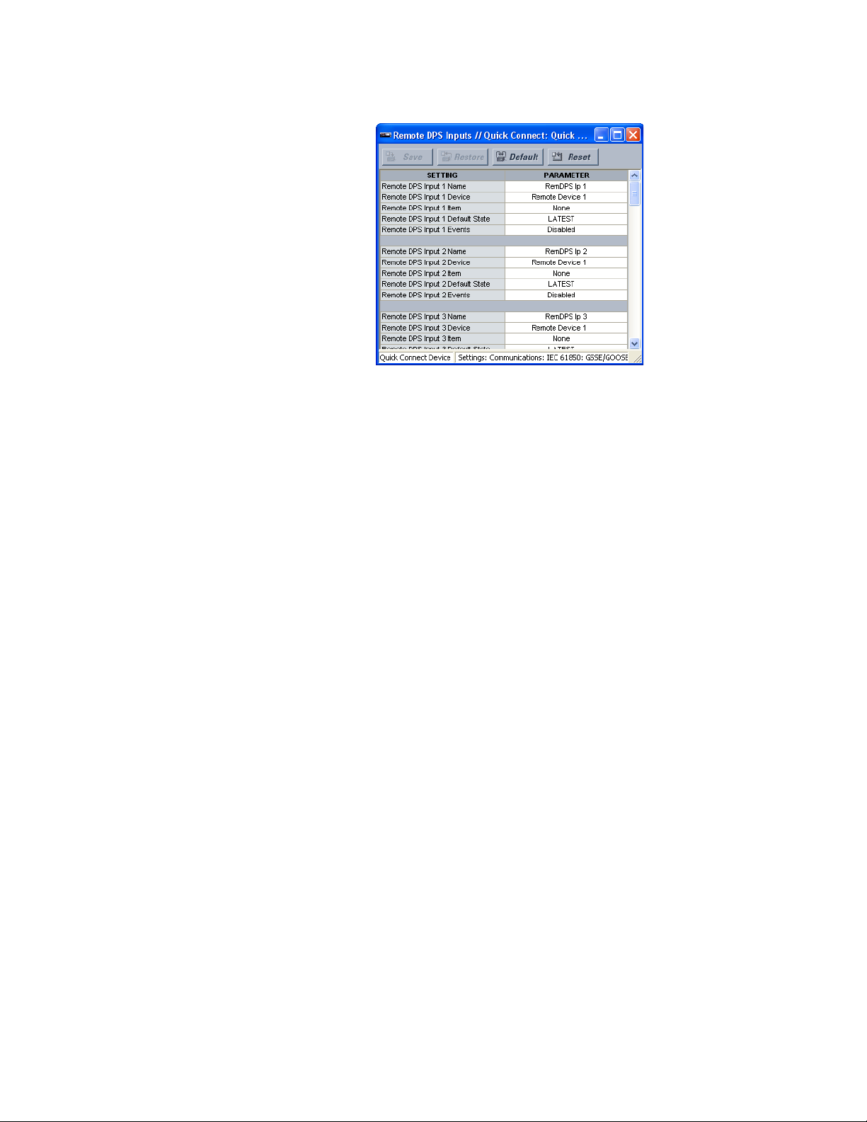
IEC 61850 COMMUNICATIONS CHAPTER 6: COMMUNICATIONS
Figure 22: Remote double-point status inputs configuration settings
The following settings are available for each of the 16 remote double-point status inputs.
Remote DPS Input Name
Range: up to 12 characters
Default: RemDPS Ip n
This setting allows the user to assign descriptive text to the remote DPS input.
Remote DPS Input Device
Range: Remote Device 1 through Remote Device 32
Default: Remote Device n
This setting selects the number (1 to 32) of the remote device that originates the required
signal, as previously assigned to the remote device via the Remote Device ID setting.
Remote DPS Input Item
Range: None, Dataset Item 1 through Dataset Item 64
Default: None
This setting specifies the required bits of the GOOSE message.
Remote DPS Input Default State
Range: Intermediate, Off, On, Bad, Latest
Default: Latest
This setting selects the default value for the offline remote double-point status input if
the relay has just completed startup or the remote device sending the data is declared
to be non-communicating.
Remote DPS Input Events
Range: Enabled, Disabled
Default: Disabled
This setting enables and disables the logging of remote double-point status input status
changes in the events recorder.
90 MULTILIN B95
Plus
BUS PROTECTION SYSTEM – INSTRUCTION MANUAL
 Loading...