

Page 1
836771A2.CDR
LISTED
52TL
IND.CONT. EQ.
E83849
GE
Digital Energy
Addendum
B90 Low Impedance Bus
Differential System
UR Series Instruction Manual
B90 revision: 7.0x
Manual P/N: 1601-0115-Y2 (GEK-113660A)
GE Digital Energy
650 Markland Street
Markham, Ontario
Canada L6C 0M1
Tel: +1 905 927 7070 Fax: +1 905 927 5098
Internet: http://www.GEDigitalEnergy.com
*1601-0115-Y2*
GE Multilin's Quality Management
System is registered to ISO
9001:2008
QMI # 005094
UL # A3775
Page 2

Copyright © 2012 GE Multilin Inc. All rights reserved.
B90 Low Impedance Bus Differential System UR Series Instruction Manual
revision 7.0x.
FlexLogic, FlexElement, FlexCurve, FlexAnalog, FlexInteger, FlexState, EnerVista,
CyberSentry, HardFiber, Digital Energy, Multilin, and GE Multilin are trademarks
or registered trademarks of GE Multilin Inc.
The contents of this manual are the property of GE Multilin Inc. This
documentation is furnished on license and may not be reproduced in whole or
in part without the permission of GE Multilin. The content of this manual is for
informational use only and is subject to change without notice.
Part number: 1601-0115-Y2 (November 2012)
Page 3

TABLE OF CONTENTS
1. GETTING STARTED 1.1 IMPORTANT PROCEDURES
1.1.1 CAUTIONS AND WARNINGS ........................................................................... 1-1
1.1.2 INSPECTION CHECKLIST ................................................................................ 1-1
1.2 UR OVERVIEW
1.2.1 INTRODUCTION TO THE UR ........................................................................... 1-2
1.2.2 HARDWARE ARCHITECTURE......................................................................... 1-3
1.2.3 UR SOFTWARE ARCHITECTURE ................................................................... 1-4
1.2.4 IMPORTANT UR CONCEPTS...........................................................................1-4
1.3 ENERVISTA UR SETUP SOFTWARE
1.3.1 REQUIREMENTS .............................................................................................. 1-5
1.3.2 SOFTWARE INSTALLATION ............................................................................ 1-5
1.3.3 CONFIGURING THE B90 FOR SOFTWARE ACCESS .................................... 1-6
1.3.4 USING THE QUICK CONNECT FEATURE....................................................... 1-9
1.3.5 CONNECTING TO THE B90 RELAY............................................................... 1-15
1.4 UR HARDWARE
1.4.1 MOUNTING AND WIRING............................................................................... 1-16
1.4.2 COMMUNICATIONS........................................................................................ 1-16
1.4.3 FACEPLATE DISPLAY.................................................................................... 1-16
1.5 USING THE RELAY
1.5.1 FACEPLATE KEYPAD..................................................................................... 1-17
1.5.2 MENU NAVIGATION ....................................................................................... 1-17
1.5.3 MENU HIERARCHY ........................................................................................ 1-17
1.5.4 RELAY ACTIVATION....................................................................................... 1-17
1.5.5 RELAY PASSWORDS..................................................................................... 1-18
1.5.6 FLEXLOGIC™ CUSTOMIZATION................................................................... 1-18
1.5.7 COMMISSIONING ........................................................................................... 1-19
2. PRODUCT DESCRIPTION 2.1 INTRODUCTION
2.1.1 OVERVIEW........................................................................................................ 2-1
2.1.2 ORDERING........................................................................................................ 2-7
2.1.3 REPLACEMENT MODULES ............................................................................. 2-9
2.2 SPECIFICATIONS
2.2.1 PROTECTION ELEMENTS ............................................................................. 2-10
2.2.2 USER-PROGRAMMABLE ELEMENTS........................................................... 2-11
2.2.3 MONITORING.................................................................................................. 2-12
2.2.4 METERING ......................................................................................................2-13
2.2.5 INPUTS ............................................................................................................ 2-13
2.2.6 POWER SUPPLY ............................................................................................2-14
2.2.7 OUTPUTS ........................................................................................................ 2-14
2.2.8 COMMUNICATIONS........................................................................................ 2-15
2.2.9 INTER-RELAY COMMUNICATIONS............................................................... 2-16
2.2.10 ENVIRONMENTAL .......................................................................................... 2-16
2.2.11 TYPE TESTS ................................................................................................... 2-17
2.2.12 PRODUCTION TESTS .................................................................................... 2-17
2.2.13 APPROVALS ................................................................................................... 2-18
2.2.14 MAINTENANCE ............................................................................................... 2-18
3. HARDWARE 3.1 DESCRIPTION
3.1.1 PANEL CUTOUT ............................................................................................... 3-1
3.1.2 MODULE WITHDRAWAL AND INSERTION ..................................................... 3-3
3.1.3 REAR TERMINAL LAYOUT............................................................................... 3-4
3.2 WIRING
3.2.1 TYPICAL WIRING.............................................................................................. 3-6
3.2.2 DIELECTRIC STRENGTH ............................................................................... 3-12
3.2.3 CONTROL POWER ......................................................................................... 3-12
3.2.4 CT AND VT MODULES ................................................................................... 3-13
3.2.5 CONTACT INPUTS AND OUTPUTS...............................................................3-14
3.2.6 RS232 FACEPLATE PORT ............................................................................. 3-22
GE Multilin B90 Low Impedance Bus Differential System iii
Page 4

TABLE OF CONTENTS
3.2.7 CPU COMMUNICATION PORTS.....................................................................3-22
3.2.8 IRIG-B...............................................................................................................3-25
3.3 DIRECT INPUT/OUTPUT COMMUNICATIONS
3.3.1 DESCRIPTION .................................................................................................3-26
3.3.2 FIBER: LED AND ELED TRANSMITTERS ......................................................3-28
3.3.3 FIBER-LASER TRANSMITTERS .....................................................................3-28
3.3.4 G.703 INTERFACE...........................................................................................3-29
3.3.5 RS422 INTERFACE .........................................................................................3-32
3.3.6 RS422 AND FIBER INTERFACE .....................................................................3-34
3.3.7 G.703 AND FIBER INTERFACE ......................................................................3-34
3.3.8 IEEE C37.94 INTERFACE................................................................................3-35
3.3.9 C37.94SM INTERFACE ...................................................................................3-38
4. HUMAN INTERFACES 4.1 ENERVISTA UR SETUP SOFTWARE INTERFACE
4.1.1 INTRODUCTION ................................................................................................4-1
4.1.2 CREATING A SITE LIST ....................................................................................4-1
4.1.3 ENERVISTA UR SETUP OVERVIEW................................................................4-1
4.1.4 ENERVISTA UR SETUP MAIN WINDOW..........................................................4-3
4.2 EXTENDED ENERVISTA UR SETUP FEATURES
4.2.1 SETTINGS TEMPLATES ...................................................................................4-4
4.2.2 SECURING AND LOCKING FLEXLOGIC™ EQUATIONS ................................4-8
4.2.3 SETTINGS FILE TRACEABILITY.....................................................................4-10
4.3 FACEPLATE INTERFACE
4.3.1 FACEPLATE.....................................................................................................4-13
4.3.2 LED INDICATORS............................................................................................4-14
4.3.3 CUSTOM LABELING OF LEDS .......................................................................4-16
4.3.4 DISPLAY...........................................................................................................4-22
4.3.5 KEYPAD ...........................................................................................................4-22
4.3.6 MENUS.............................................................................................................4-22
4.3.7 CHANGING SETTINGS ...................................................................................4-24
5. SETTINGS 5.1 OVERVIEW
5.1.1 SETTINGS MENU ..............................................................................................5-1
5.1.2 INTRODUCTION TO ELEMENTS......................................................................5-3
5.2 PRODUCT SETUP
5.2.1 B90 FUNCTION..................................................................................................5-5
5.2.2 SECURITY..........................................................................................................5-5
5.2.3 CYBERSENTRY SECURITY..............................................................................5-9
5.2.4 DISPLAY PROPERTIES ..................................................................................5-15
5.2.5 CLEAR RELAY RECORDS ..............................................................................5-16
5.2.6 COMMUNICATIONS ........................................................................................5-17
5.2.7 MODBUS USER MAP ......................................................................................5-39
5.2.8 REAL TIME CLOCK .........................................................................................5-39
5.2.9 USER-PROGRAMMABLE FAULT REPORT....................................................5-44
5.2.10 OSCILLOGRAPHY ...........................................................................................5-45
5.2.11 USER-PROGRAMMABLE LEDS .....................................................................5-47
5.2.12 USER-PROGRAMMABLE SELF TESTS .........................................................5-50
5.2.13 CONTROL PUSHBUTTONS ............................................................................5-50
5.2.14 USER-PROGRAMMABLE PUSHBUTTONS....................................................5-52
5.2.15 FLEX STATE PARAMETERS ..........................................................................5-57
5.2.16 USER-DEFINABLE DISPLAYS........................................................................5-58
5.2.17 DIRECT INPUTS AND OUTPUTS....................................................................5-60
5.2.18 INSTALLATION ................................................................................................5-68
5.3 SYSTEM SETUP
5.3.1 AC INPUTS.......................................................................................................5-69
5.3.2 POWER SYSTEM ............................................................................................5-70
5.3.3 FLEXCURVES™ ..............................................................................................5-71
5.3.4 BUS ..................................................................................................................5-78
iv B90 Low Impedance Bus Differential System GE Multilin
Page 5

TABLE OF CONTENTS
5.4 FLEXLOGIC
5.4.1 INTRODUCTION TO FLEXLOGIC .................................................................. 5-80
5.4.2 FLEXLOGIC RULES ........................................................................................ 5-86
5.4.3 FLEXLOGIC EVALUATION ............................................................................. 5-86
5.4.4 FLEXLOGIC EXAMPLE ................................................................................... 5-87
5.4.5 FLEXLOGIC EQUATION EDITOR................................................................... 5-91
5.4.6 FLEXLOGIC TIMERS ...................................................................................... 5-91
5.4.7 NON-VOLATILE LATCHES ............................................................................. 5-92
5.5 GROUPED ELEMENTS
5.5.1 OVERVIEW...................................................................................................... 5-93
5.5.2 SETTING GROUP ........................................................................................... 5-93
5.5.3 BUS DIFFERENTIAL ....................................................................................... 5-94
5.5.4 BREAKER FAILURE........................................................................................ 5-98
5.5.5 VOLTAGE ELEMENTS.................................................................................. 5-106
5.5.6 CURRENT ELEMENTS ................................................................................. 5-107
5.5.7 END FAULT PROTECTION........................................................................... 5-114
5.6 CONTROL ELEMENTS
5.6.1 OVERVIEW.................................................................................................... 5-117
5.6.2 TRIP BUS....................................................................................................... 5-117
5.6.3 SETTING GROUPS ....................................................................................... 5-119
5.6.4 DIGITAL ELEMENTS..................................................................................... 5-120
5.6.5 MONITORING ELEMENTS ........................................................................... 5-123
5.7 INPUTS/OUTPUTS
5.7.1 CONTACT INPUTS........................................................................................ 5-127
5.7.2 5VIRTUAL INPUTS........................................................................................ 5-129
5.7.3 CONTACT OUTPUTS.................................................................................... 5-130
5.7.4 VIRTUAL OUTPUTS...................................................................................... 5-132
5.7.5 REMOTE DEVICES....................................................................................... 5-133
5.7.6 REMOTE INPUTS.......................................................................................... 5-134
5.7.7 REMOTE DOUBLE-POINT STATUS INPUTS .............................................. 5-135
5.7.8 REMOTE OUTPUTS...................................................................................... 5-135
5.7.9 RESETTING................................................................................................... 5-136
5.7.10 DIRECT INPUTS AND OUTPUTS................................................................. 5-136
5.7.11 IEC 61850 GOOSE ANALOGS...................................................................... 5-140
5.7.12 IEC 61850 GOOSE INTEGERS..................................................................... 5-141
5.8 TESTING
5.8.1 TEST MODE .................................................................................................. 5-142
5.8.2 FORCE CONTACT INPUTS .......................................................................... 5-143
5.8.3 FORCE CONTACT OUTPUTS ...................................................................... 5-144
6. ACTUAL VALUES 6.1 OVERVIEW
6.1.1 ACTUAL VALUES MAIN MENU ........................................................................ 6-1
6.2 STATUS
6.2.1 CONTACT INPUTS............................................................................................ 6-3
6.2.2 VIRTUAL INPUTS.............................................................................................. 6-3
6.2.3 REMOTE INPUTS.............................................................................................. 6-3
6.2.4 REMOTE DOUBLE-POINT STATUS INPUTS .................................................. 6-4
6.2.5 CONTACT OUTPUTS........................................................................................ 6-4
6.2.6 VIRTUAL OUTPUTS.......................................................................................... 6-4
6.2.7 REMOTE DEVICES........................................................................................... 6-5
6.2.8 FLEX STATES ................................................................................................... 6-5
6.2.9 ETHERNET........................................................................................................ 6-6
6.2.10 REAL TIME CLOCK SYNCHRONIZING............................................................ 6-6
6.2.11 IEC 61850 GOOSE INTEGERS......................................................................... 6-7
6.2.12 DIRECT INPUTS................................................................................................ 6-7
6.2.13 DIRECT DEVICES STATUS.............................................................................. 6-8
6.2.14 REMAINING CONNECTION STATUS .............................................................. 6-8
6.3 METERING
6.3.1 METERING CONVENTIONS.............................................................................6-9
6.3.2 BUS ZONE......................................................................................................... 6-9
6.3.3 CURRENTS ..................................................................................................... 6-10
GE Multilin B90 Low Impedance Bus Differential System v
Page 6

TABLE OF CONTENTS
6.3.4 VOLTAGES ......................................................................................................6-10
6.3.5 FREQUENCY ...................................................................................................6-10
6.3.6 IEC 61580 GOOSE ANALOG VALUES ...........................................................6-11
6.4 RECORDS
6.4.1 USER-PROGRAMMABLE FAULT REPORTS .................................................6-12
6.4.2 EVENT RECORDS...........................................................................................6-12
6.4.3 OSCILLOGRAPHY ...........................................................................................6-12
6.5 PRODUCT INFORMATION
6.5.1 MODEL INFORMATION...................................................................................6-13
6.5.2 FIRMWARE REVISIONS..................................................................................6-13
7. COMMANDS AND
TARGETS
7.1 COMMANDS
7.1.1 COMMANDS MENU...........................................................................................7-1
7.1.2 VIRTUAL INPUTS ..............................................................................................7-1
7.1.3 CLEAR RECORDS.............................................................................................7-2
7.1.4 SET DATE AND TIME ........................................................................................7-2
7.1.5 RELAY MAINTENANCE.....................................................................................7-3
7.1.6 SECURITY..........................................................................................................7-3
7.2 TARGETS
7.2.1 TARGETS MENU ...............................................................................................7-5
7.2.2 TARGET MESSAGES ........................................................................................7-5
7.2.3 RELAY SELF-TESTS .........................................................................................7-5
8. SECURITY 8.1 USER ACCOUNTS
8.1.1 OVERVIEW ........................................................................................................8-1
8.1.2 ENABLING THE SECURITY MANAGEMENT SYSTEM....................................8-1
8.1.3 ADDING A NEW USER ......................................................................................8-1
8.1.4 MODIFYING USER PRIVILEGES......................................................................8-2
8.2 CYBERSENTRY
8.2.1 OVERVIEW ........................................................................................................8-4
8.2.2 SECURITY MENU ..............................................................................................8-6
9. THEORY OF OPERATION 9.1 INTRODUCTION
9.1.1 BUS DIFFERENTIAL PROTECTION .................................................................9-1
9.2 DYNAMIC BUS REPLICA
9.2.1 DYNAMIC BUS REPLICA MECHANISM............................................................9-2
9.2.2 CT RATIO MATCHING.......................................................................................9-2
9.3 DIFFERENTIAL PRINCIPLE
9.3.1 BIASED DIFFERENTIAL CHARACTERISTIC....................................................9-3
9.3.2 DIFFERENTIAL AND RESTRAINING CURRENTS ...........................................9-4
9.3.3 ENHANCED SECURITY ....................................................................................9-5
9.4 DIRECTIONAL PRINCIPLE
9.4.1 CURRENT DIRECTIONAL PROTECTION.........................................................9-6
9.5 SATURATION DETECTOR
9.5.1 CT SATURATION DETECTION .........................................................................9-7
9.6 OUTPUT LOGIC AND EXAMPLES
9.6.1 OUTPUT LOGIC.................................................................................................9-8
9.6.2 INTERNAL AND EXTERNAL FAULT EXAMPLE ...............................................9-8
10. APPLICATION OF
SETTINGS
10.1 OVERVIEW
10.1.1 INTRODUCTION ..............................................................................................10-1
vi B90 Low Impedance Bus Differential System GE Multilin
Page 7

TABLE OF CONTENTS
10.1.2 SAMPLE BUSBAR AND DATA........................................................................ 10-1
10.2 ZONING AND DYNAMIC BUS REPLICA
10.2.1 NORTH BUS ZONE ......................................................................................... 10-3
10.2.2 SOUTH BUS ZONE ......................................................................................... 10-3
10.3 BIASED CHARACTERISTIC BREAKPOINTS
10.3.1 DESCRIPTION................................................................................................. 10-4
10.3.2 HIGH BREAKPOINT ........................................................................................ 10-4
10.3.3 LOW BREAKPOINT......................................................................................... 10-5
10.4 SLOPES AND HIGH SET THRESHOLD
10.4.1 DESCRIPTION................................................................................................. 10-6
10.4.2 EXTERNAL FAULTS ON C-1 .......................................................................... 10-6
10.4.3 EXTERNAL FAULTS ON C-2 .......................................................................... 10-7
10.4.4 EXTERNAL FAULTS ON C-3 .......................................................................... 10-7
10.4.5 EXTERNAL FAULTS ON C-4 .......................................................................... 10-8
10.4.6 EXTERNAL FAULTS ON C-5 .......................................................................... 10-8
10.5 BUS DIFFERENTIAL SETTINGS
10.5.1 DESCRIPTION................................................................................................. 10-9
10.6 ENHANCING RELAY PERFORMANCE
10.6.1 USING SETTING GROUPS........................................................................... 10-10
A. FLEXANALOG AND
FLEXINTEGER
PARAMETERS
B. MODBUS
COMMUNICATIONS
A.1 PARAMETER LISTS
A.1.1 FLEXANALOG ITEMS ....................................................................................... A-1
A.1.2 FLEXINTEGER ITEMS ...................................................................................... A-3
B.1 MODBUS RTU PROTOCOL
B.1.1 INTRODUCTION................................................................................................B-1
B.1.2 PHYSICAL LAYER.............................................................................................B-1
B.1.3 DATA LINK LAYER............................................................................................B-1
B.1.4 CRC-16 ALGORITHM........................................................................................B-2
B.2 MODBUS FUNCTION CODES
B.2.1 SUPPORTED FUNCTION CODES ...................................................................B-3
B.2.2 READ ACTUAL VALUES OR SETTINGS (FUNCTION CODE 03/04H) ...........B-3
B.2.3 EXECUTE OPERATION (FUNCTION CODE 05H) ...........................................B-4
B.2.4 STORE SINGLE SETTING (FUNCTION CODE 06H).......................................B-4
B.2.5 STORE MULTIPLE SETTINGS (FUNCTION CODE 10H) ................................B-5
B.2.6 EXCEPTION RESPONSES...............................................................................B-5
B.3 FILE TRANSFERS
B.3.1 OBTAINING RELAY FILES VIA MODBUS........................................................ B-6
B.3.2 MODBUS PASSWORD OPERATION ...............................................................B-7
B.4 MEMORY MAPPING
B.4.1 MODBUS MEMORY MAP .................................................................................B-8
B.4.2 DATA FORMATS .............................................................................................B-56
C. IEC 61850
COMMUNICATIONS
C.1 OVERVIEW
C.1.1 INTRODUCTION................................................................................................C-1
C.1.2 COMMUNICATION PROFILES .........................................................................C-1
C.2 SERVER DATA ORGANIZATION
C.2.1 OVERVIEW........................................................................................................C-2
C.2.2 GGIO1: DIGITAL STATUS VALUES .................................................................C-2
C.2.3 GGIO2: DIGITAL CONTROL VALUES..............................................................C-2
C.2.4 GGIO3: DIGITAL STATUS AND ANALOG VALUES FROM RECEIVED GOOSE
DATAC-2
C.2.5 GGIO4: GENERIC ANALOG MEASURED VALUES .........................................C-2
C.2.6 MMXN: ANALOG MEASURED VALUES...........................................................C-3
GE Multilin B90 Low Impedance Bus Differential System vii
Page 8

TABLE OF CONTENTS
C.2.7 PROTECTION AND OTHER LOGICAL NODES............................................... C-3
C.3 SERVER FEATURES AND CONFIGURATION
C.3.1 BUFFERED AND UNBUFFERED REPORTING...............................................C-5
C.3.2 FILE TRANSFER...............................................................................................C-5
C.3.3 TIMESTAMPS AND SCANNING....................................................................... C-5
C.3.4 LOGICAL DEVICE NAME ................................................................................. C-5
C.3.5 LOCATION ........................................................................................................ C-5
C.3.6 LOGICAL NODE NAME PREFIXES.................................................................. C-6
C.3.7 CONNECTION TIMING.....................................................................................C-6
C.3.8 NON-IEC 61850 DATA...................................................................................... C-6
C.3.9 COMMUNICATION SOFTWARE UTILITIES.....................................................C-6
C.4 GENERIC SUBSTATION EVENT SERVICES: GSSE AND GOOSE
C.4.1 OVERVIEW ....................................................................................................... C-7
C.4.2 GSSE CONFIGURATION..................................................................................C-7
C.4.3 FIXED GOOSE..................................................................................................C-7
C.4.4 CONFIGURABLE GOOSE ................................................................................ C-7
C.4.5 ETHERNET MAC ADDRESS FOR GSSE/GOOSE ........................................ C-10
C.4.6 GSSE ID AND GOOSE ID SETTINGS............................................................C-10
C.5 IEC 61850 IMPLEMENTATION VIA ENERVISTA UR SETUP
C.5.1 OVERVIEW ..................................................................................................... C-11
C.5.2 CONFIGURING IEC 61850 SETTINGS .......................................................... C-12
C.5.3 ABOUT ICD FILES .......................................................................................... C-13
C.5.4 CREATING AN ICD FILE WITH ENERVISTA UR SETUP..............................C-17
C.5.5 ABOUT SCD FILES......................................................................................... C-17
C.5.6 IMPORTING AN SCD FILE WITH ENERVISTA UR SETUP........................... C-20
C.6 ACSI CONFORMANCE
C.6.1 ACSI BASIC CONFORMANCE STATEMENT ................................................ C-22
C.6.2 ACSI MODELS CONFORMANCE STATEMENT............................................C-22
C.6.3 ACSI SERVICES CONFORMANCE STATEMENT ......................................... C-23
C.7 LOGICAL NODES
C.7.1 LOGICAL NODES TABLE ...............................................................................C-26
D. IEC 60870-5-104
COMMUNICATIONS
D.1 IEC 60870-5-104
D.1.1 INTEROPERABILITY DOCUMENT...................................................................D-1
D.1.2 IEC 60870-5-104 POINTS .................................................................................D-9
E. DNP COMMUNICATIONS E.1 DEVICE PROFILE DOCUMENT
E.1.1 DNP V3.00 DEVICE PROFILE .......................................................................... E-1
E.1.2 IMPLEMENTATION TABLE .............................................................................. E-4
E.2 DNP POINT LISTS
E.2.1 BINARY INPUT POINTS ................................................................................... E-8
E.2.2 BINARY AND CONTROL RELAY OUTPUT...................................................... E-9
E.2.3 ANALOG INPUTS............................................................................................ E-10
F. MISCELLANEOUS F.1 CHANGE NOTES
F.1.1 REVISION HISTORY......................................................................................... F-1
F.1.2 CHANGES TO THE B90 MANUAL ................................................................... F-1
F.2 ABBREVIATIONS
F.2.1 STANDARD ABBREVIATIONS ....................................................................... F-12
F.3 WARRANTY
F.3.1 GE MULTILIN WARRANTY............................................................................. F-16
viii B90 Low Impedance Bus Differential System GE Multilin
Page 9
1 GETTING STARTED 1.1 IMPORTANT PROCEDURES
NOTE
1 GETTING STARTED 1.1IMPORTANT PROCEDURES
Read this chapter to help guide you through the initial setup of your new B90 Low Impedance Bus Differential System.
1.1.1 CAUTIONS AND WARNINGS
Before attempting to install or use the device, review all safety indicators in this document to help prevent injury,
equipment damage, or downtime.
The following safety and equipment symbols are used in this document.
Indicates a hazardous situation which, if not avoided, will result in death or serious injury.
Indicates a hazardous situation which, if not avoided, could result in death or serious injury.
Indicates a hazardous situation which, if not avoided, could result in minor or moderate
injury.
Indicates practices not related to personal injury.
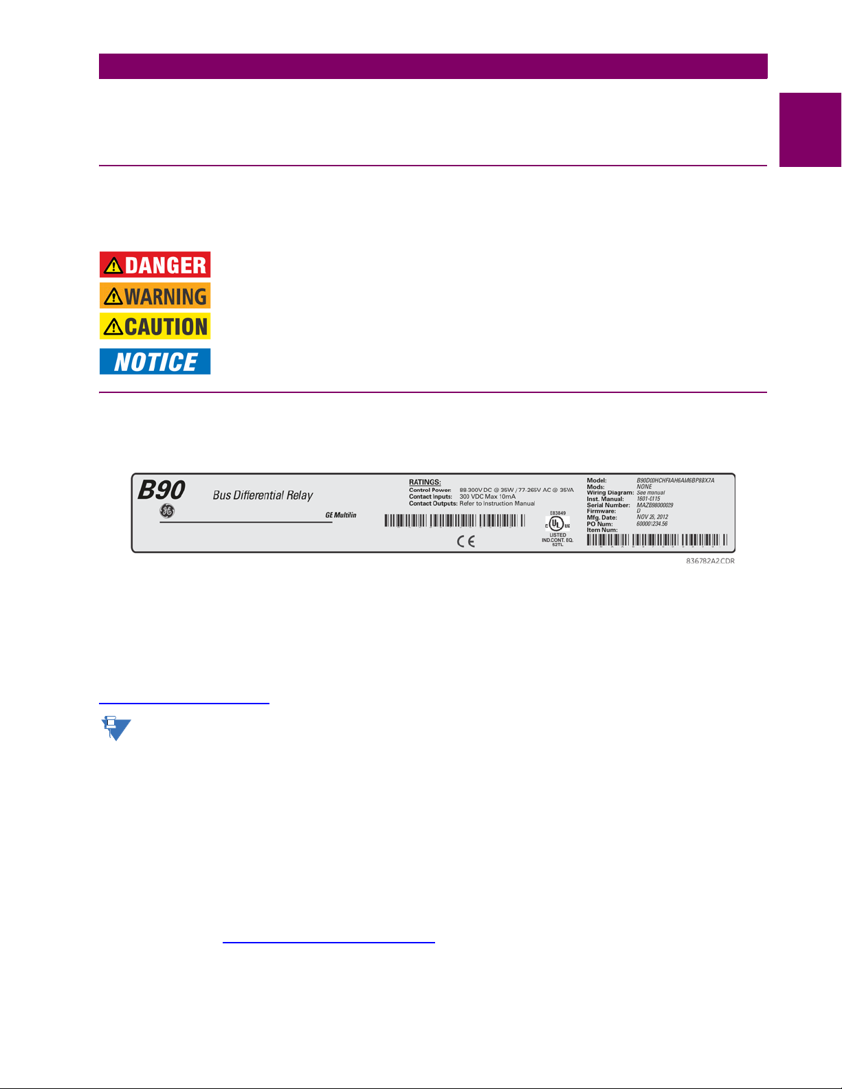
1.1.2 INSPECTION CHECKLIST
1. Open the relay packaging and inspect the unit for physical damage.
2. View the rear nameplate and verify that the correct model has been ordered and delivered.
1
Figure 1–1: REAR NAMEPLATE (EXAMPLE)
3. Ensure that the following items are included:
• Instruction manual (if ordered)
• GE EnerVista™ CD (includes the EnerVista UR Setup software and manuals in PDF format)
• Mounting screws
For product information, instruction manual updates, and the latest software updates, visit the GE Digital Energy website at
http://www.gedigitalenergy.com
If there is any noticeable physical damage, or any of the contents listed are missing, please contact GE Digital
Energy immediately.
GE DIGITAL ENERGY CONTACT INFORMATION AND CALL CENTER FOR PRODUCT SUPPORT:
GE Digital Energy
650 Markland Street
Markham, Ontario
Canada L6C 0M1
TELEPHONE: Worldwide +1 905 927 7070
Europe/Middle East/Africa +34 94 4854 88 54
North America toll-free 1 800 547 8629
FAX: +1 905 927 5098
EMAIL: multilin.tech@ge.com
HOME PAGE: http://www.gedigitalenergy.com/multilin
.
GE Multilin B90 Low Impedance Bus Differential System 1-1
Page 10

1.2 UR OVERVIEW 1 GETTING STARTED
1.2UR OVERVIEW 1.2.1 INTRODUCTION TO THE UR
1
Historically, substation protection, control, and metering functions were performed with electromechanical equipment. This
equipment was gradually replaced by analog equipment, most of which emulated the single-function approach of their electromechanical precursors. Both technologies required expensive cabling and auxiliary equipment to produce functioning
systems.
Recently, digital electronic equipment has begun to provide protection, control, and metering functions. Initially, this equipment was either single function or had very limited multifunction capability, and it did not significantly reduce the cabling and
auxiliary equipment required. However, recent digital relays are multifunctional, reducing cabling and auxiliaries significantly. These devices also transfer data to central control facilities and software using electronic communications. The
functions performed have become so broad that many users now prefer the term Intelligent Electronic Device (IED).
It is obvious to station designers that the amount of cabling and auxiliary equipment installed can be even further reduced,
to 20% to 70% of levels common in 1990, and achieve large cost reductions. This requires placing even more functions
within the IEDs.
Users of power equipment are also interested in reducing cost by improving power quality and personnel productivity, and
in increasing system reliability and efficiency. These objectives are realized through software that is used to perform functions at both the station and supervisory levels. The use of these systems is growing rapidly.
High-speed communication is required to meet the data transfer rates required by modern automatic control and monitoring
systems. Very high speed communications are required to perform protection signaling with a performance target response
time for a command signal between two IEDs, from transmission to reception, of less than 3 milliseconds. This has been
established by the IEC 61850 standard.
IEDs with such capabilities also provide significantly more power system data than was available, enhanced operations and
maintenance, and permit the use of adaptive system configuration for protection and control systems. This new generation
of equipment is easily incorporated into automation systems, at both the station and enterprise levels. The GE Multilin Universal Relay (UR) series meets these goals.
1-2 B90 Low Impedance Bus Differential System GE Multilin
Page 11

1 GETTING STARTED 1.2 UR OVERVIEW
1.2.2 HARDWARE ARCHITECTURE
a) UR BASIC DESIGN
The UR is a digital-based device containing a central processing unit (CPU) that handles multiple types of input and output
signals. The UR device can communicate over a local area network (LAN) with an operator interface, a programming
device, or another UR device.
Figure 1–2: UR CONCEPT BLOCK DIAGRAM
The CPU module contains firmware that provides protection elements in the form of logic algorithms, as well as programmable logic gates, timers, and latches for control features.
Input elements accept a variety of analog or digital signals from the field. The UR isolates and converts these signals into
logic signals used by the relay.
Output elements convert and isolate the logic signals generated by the relay into digital or analog signals that can be used
to control field devices.
1
b) UR SIGNAL TYPES
The contact inputs and outputs are digital signals associated with connections to hard-wired contacts. Both ‘wet’ and ‘dry’
contacts are supported.
The virtual inputs and outputs are digital signals associated with UR-series internal logic signals. Virtual inputs include
signals generated by the local user interface. The virtual outputs are outputs of FlexLogic™ equations used to customize
the device. Virtual outputs can also serve as virtual inputs to FlexLogic equations.
The analog inputs and outputs are signals that are associated with transducers, such as Resistance Temperature Detec-
tors (RTDs).
The CT and VT inputs refer to analog current transformer and voltage transformer signals used to monitor AC power lines.
The UR-series relays support 1 A and 5 A CTs.
The remote inputs and outputs provide a means of sharing digital point state information between remote UR-series
devices. The remote outputs interface to the remote inputs of other UR-series devices. Remote outputs are FlexLogic operands inserted into IEC 61850 GSSE and GOOSE messages.
The direct inputs and outputs provide a means of sharing digital point states between a number of UR-series IEDs over a
dedicated fiber (single or multimode), RS422, or G.703 interface. No switching equipment is required as the IEDs are connected directly in a ring or redundant (dual) ring configuration. This feature is optimized for speed and intended for pilotaided schemes, distributed logic applications, or the extension of the input/output capabilities of a single relay chassis.
GE Multilin B90 Low Impedance Bus Differential System 1-3
Page 12
1.2 UR OVERVIEW 1 GETTING STARTED
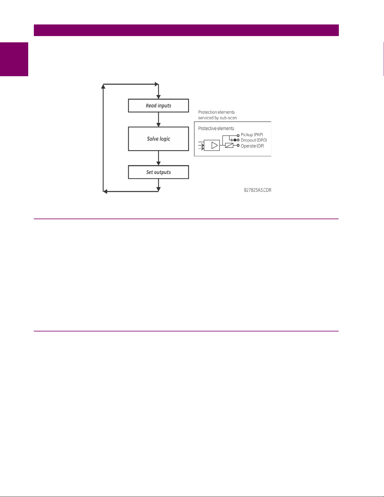
c) UR SCAN OPERATION
The UR-series devices operate in a cyclic scan fashion. The device reads the inputs into an input status table, solves the
1
logic program (FlexLogic equation), and then sets each output to the appropriate state in an output status table. Any resulting task execution is priority interrupt-driven.
Figure 1–3: UR-SERIES SCAN OPERATION
1.2.3 UR SOFTWARE ARCHITECTURE
The firmware (software embedded in the relay) is designed in functional modules that can be installed in any relay as
required. This is achieved with object-oriented design and programming (OOD/OOP) techniques.
Object-oriented techniques involve the use of objects and classes. An object is defined as “a logical entity that contains
both data and code that manipulates that data”. A class is the generalized form of similar objects. By using this concept,
one can create a protection class with the protection elements as objects of the class, such as time overcurrent, instantaneous overcurrent, current differential, undervoltage, overvoltage, underfrequency, and distance. These objects represent
completely self-contained software modules. The same object-class concept can be used for metering, input/output control,
software interface, communications, or any functional entity in the system.
Employing OOD/OOP in the software architecture of the B90 achieves the same features as the hardware architecture:
modularity, scalability, and flexibility. The application software for any UR-series device (for example, feeder protection,
transformer protection, distance protection) is constructed by combining objects from the various functional classes. This
results in a common interface across the UR series.
1.2.4 IMPORTANT UR CONCEPTS
As described above, the architecture of the UR-series relays differ from previous devices. To achieve a general understanding of this device, some sections of Chapter 5 are quite helpful. The most important functions of the relay are contained in
“elements”. A description of the UR-series elements can be found in the Introduction to elements section in chapter 5.
Examples of simple elements, and some of the organization of this manual, can be found in the Control elements section of
chapter 5. A description of how digital signals are used and routed within the relay is contained in the Introduction to Flex-
Logic section in chapter 5.
1-4 B90 Low Impedance Bus Differential System GE Multilin
Page 13

1 GETTING STARTED 1.3 ENERVISTA UR SETUP SOFTWARE
1.3ENERVISTA UR SETUP SOFTWARE 1.3.1 REQUIREMENTS
The faceplate keypad and display or the EnerVista UR Setup software can be used to communicate with the relay. The
EnerVista UR Setup software interface is the preferred method to edit settings and view actual values because the computer monitor can display more information in a simple comprehensible format.
The following minimum requirements must be met for the EnerVista UR Setup software to properly operate on a computer:
• Pentium class or higher processor (Pentium II 300 MHz or higher recommended)
• Windows 95, 98, 98SE, ME, NT 4.0 (Service Pack 4 or higher), 2000, XP
• Internet Explorer 4.0 or higher
• 128 MB of RAM (256 MB recommended)
• 200 MB of available space on system drive and 200 MB of available space on installation drive
• Video capable of displaying 800 x 600 or higher in high-color mode (16-bit color)
• RS232 and/or Ethernet port for communications to the relay
The following qualified modems have been tested to be compliant with the B90 and the EnerVista UR Setup software:
• US Robotics external 56K FaxModem 5686
• US Robotics external Sportster 56K X2
• PCTEL 2304WT V.92 MDC internal modem
1.3.2 SOFTWARE INSTALLATION
After ensuring the minimum requirements for using EnerVista UR Setup are met (previous section), install the EnerVista UR
Setup from the GE EnerVista CD. Or download the UR EnerVista software from http://www.gedigitalenergy.com/multilin
and install it.
1. Insert the GE EnerVista CD into your CD-ROM drive.
2. Click the Install Now button and follow the installation instructions to install the EnerVista software.
3. When installation is complete, start the EnerVista Launchpad application.
4. Click the IED Setup section of the Launch Pad window.
1
5. In the EnerVista Launch Pad window, click the Add Product button and select the appropriate product, shown as
follows. Select the "Web" option to ensure the most recent software release, or select "CD" if you do not have a web
GE Multilin B90 Low Impedance Bus Differential System 1-5
Page 14

1.3 ENERVISTA UR SETUP SOFTWARE 1 GETTING STARTED
connection, then click the Add Now button to list software items for the product. EnerVista Launchpad then obtains the
software from the Internet or CD and automatically starts the installation program.
1
6. Select the complete path, including the new directory name, where the EnerVista UR Setup is to be installed.
7. Click on Next to begin the installation. The files are installed in the directory indicated, and the installation program
automatically creates icons and adds EnerVista UR Setup to the Windows start menu.
8. Click Finish to complete the installation. The UR-series device is added to the list of installed IEDs in the EnerVista
Launchpad window, as shown.
1.3.3 CONFIGURING THE B90 FOR SOFTWARE ACCESS
a) OVERVIEW
The user can connect remotely to the B90 through the rear RS485 port or the rear Ethernet port with a computer running
the EnerVista UR Setup software. The B90 can also be accessed locally with a laptop computer through the front panel
RS232 port or the rear Ethernet port using the Quick Connect feature.
• To configure the B90 for remote access via the rear RS485 port, see the Configuring Serial Communications section.
1-6 B90 Low Impedance Bus Differential System GE Multilin
Page 15

1 GETTING STARTED 1.3 ENERVISTA UR SETUP SOFTWARE
• To configure the B90 for remote access via the rear Ethernet port, see the Configuring Ethernet Communications sec-
tion. An Ethernet module must be specified at the time of ordering.
• To configure the B90 for local access with a laptop through either the front RS232 port or rear Ethernet port, see the
Using the Quick Connect Feature section.
b) CONFIGURING SERIAL COMMUNICATIONS
Before starting, verify that the serial cable is properly connected to the RS485 terminal on the back of the device. The faceplate RS232 port is intended for local use and is not described in this section; see the Using the Quick Connect Feature
section.
A GE Multilin F485 converter (or compatible RS232-to-RS485 converter) is required. Refer to the F485 instruction manual
for details.
1. Verify that the latest version of the EnerVista UR Setup software is installed (available from the GE EnerVista CD or
online from http://www.gedigitalenergy.com/multilin
2. Select the “UR” device from the EnerVista Launchpad to start EnerVista UR Setup.
3. Click the Device Setup button to open the Device Setup window and click the Add Site button to define a new site.
4. Enter a site name in the “Site Name” field. Optionally add a short description of the site along with the display order of
devices defined for the site. In this example, we use “Location 1” as the site name. Click the OK button when complete.
The new site appears in the upper-left list in the EnerVista UR Setup window.
5. Click the Device Setup button, then select the new site to re-open the Device Setup window.
6. Click the Add Device button to define the new device.
7. Enter a name in the "Device Name” field and a description (optional) of the site.
8. Select “Serial” from the Interface drop-down list. This displays a number of interface parameters that must be entered
for serial communications.
). See the Software Installation section if not already installed.
1
Figure 1–4: CONFIGURING SERIAL COMMUNICATIONS
9. Enter the relay slave address, COM port, baud rate, and parity settings from the
COMMUNICATIONS SERIAL PORTS menu in their respective fields.
GE Multilin B90 Low Impedance Bus Differential System 1-7
SETTINGS PRODUCT SETUP
Page 16

1.3 ENERVISTA UR SETUP SOFTWARE 1 GETTING STARTED
10. Click the Read Order Code button to connect to the B90 device and upload the order code. If a communications error
1
occurs, ensure that the EnerVista UR Setup serial communications values entered in the previous step correspond to
the relay setting values.
11. Click the OK button when the relay order code has been received. The new device is added to the Site List window (or
Online window) located in the top left corner of the main EnerVista UR Setup window.
The device has now been configured for RS232 communications. Proceed to the Connecting to the B90 section to begin
communication.
c) CONFIGURING ETHERNET COMMUNICATIONS
Before starting, verify that the Ethernet network cable is properly connected to the Ethernet port on the back of the relay. To
setup the relay for Ethernet communications, you define a Site, then add the relay as a Device at that site.The computer
and UR device must be on the same subnet.
1. Verify that the latest version of the EnerVista UR Setup software is installed (available from the GE EnerVista CD or
online from http://www.gedigitalenergy.com/multilin
2. Select the “UR” device from the EnerVista Launchpad to start EnerVista UR Setup.
3. Click the Device Setup button to open the Device Setup window, then click the Add Site button to define a new site.
4. Enter the desired site name in the “Site Name” field. If desired, a short description of site can also be entered along
with the display order of devices defined for the site. In this example, we use “Location 2” as the site name. Click the
OK button when complete.
5. The new site appears in the upper-left list in the EnerVista UR Setup window. Click the Device Setup button then
select the new site to re-open the Device Setup window.
6. Click the Add Device button to define the new device.
7. Enter the desired name in the “Device Name” field and a description (optional) of the site.
8. Select “Ethernet” from the Interface drop-down list. This displays a number of interface parameters that must be
entered for proper Ethernet functionality.
). See the Software Installation section for installation details.
Figure 1–5: CONFIGURING ETHERNET COMMUNICATIONS
9. Enter the relay IP address specified in the
ADDRESS in the “IP Address” field.
1-8 B90 Low Impedance Bus Differential System GE Multilin
SETTINGS PRODUCT SETUP COMMUNICATIONS NETWORK IP
Page 17

1 GETTING STARTED 1.3 ENERVISTA UR SETUP SOFTWARE
10. Enter the relay slave address and Modbus port address values from the respective settings in the SETTINGS
PRODUCT SETUP COMMUNICATIONS MODBUS PROTOCOL menu.
11. Click the Read Order Code button to connect to the B90 device and upload the order code. If an communications
error occurs, ensure that the three EnerVista UR Setup values entered in the previous steps correspond to the relay
setting values.
12. Click OK when the relay order code has been received. The new device is added to the Site List window (or Online
window) located in the top left corner of the main EnerVista UR Setup window.
The Site Device has now been configured for Ethernet communications. Proceed to the Connecting to the B90 section to
begin communications.
1.3.4 USING THE QUICK CONNECT FEATURE
a) USING QUICK CONNECT VIA THE FRONT PANEL RS232 PORT
Before starting, verify that the serial cable is properly connected from the computer to the front panel RS232 port with a
straight-through 9-pin to 9-pin RS232 cable.
1. Verify that the latest version of the EnerVista UR Setup software is installed (available from the GE EnerVista CD or
online from http://www.gedigitalenergy.com/multilin
2. Select the “UR” device from the EnerVista Launchpad to start EnerVista UR Setup.
3. Click the Quick Connect button to open the Quick Connect dialog box.
). See the Software Installation section if not already installed.
1
4. Select the Serial interface and the correct COM Port, then click Connect.
5. The EnerVista UR Setup software creates a site named “Quick Connect” with a corresponding device also named
“Quick Connect” and displays them at the upper-left of the screen. Expand the sections to view data directly from the
B90 device.
Each time that the EnerVista UR Setup software is initialized, click the Quick Connect button to establish direct communications to the B90 device. This ensures that configuration of the EnerVista UR Setup software matches the B90 model
number.
b) USING QUICK CONNECT VIA THE REAR ETHERNET PORTS
To use the Quick Connect feature to access the B90 from a computer through Ethernet, first assign an IP address to the
relay from the front panel keyboard.
1. Press the MENU key until the SETTINGS menu displays.
2. Navigate to the
3. Enter an IP address, for example “1.1.1.1,” and select the ENTER key to save the value.
4. In the same menu, select the
5. Enter a subnet IP address, for example “255.0.0.0,” and press the ENTER key to save the value.
SETTINGS PRODUCT SETUP COMMUNICATIONS NETWORK IP ADDRESS setting.
SUBNET IP MASK setting.
GE Multilin B90 Low Impedance Bus Differential System 1-9
Page 18

1.3 ENERVISTA UR SETUP SOFTWARE 1 GETTING STARTED
842799A1.CDR
END 1 END 2
Pin Wire color Diagram Pin Wire color Diagram
1 White/orange 1 White/green
2 Orange 2 Green
3 White/green 3 White/orange
4 Blue 4 Blue
5 White/blue 5 White/blue
6 Green 6 Orange
7 White/brown 7 White/brown
8 Brown 8 Brown
1
2
3
4
5
6
7
8
Next, use an Ethernet cross-over cable to connect the computer to the rear Ethernet port. In case you need it, the figure
shows the pinout for an Ethernet cross-over cable.
1
Figure 1–6: ETHERNET CROSS-OVER CABLE PIN LAYOUT
Now, assign the computer an IP address compatible with the relay’s IP address.
1. From the Windows desktop, right-click the My Network Places icon and select Properties to open the network
connections window.
2. Right-click the Local Area Connection icon and select Properties.
1-10 B90 Low Impedance Bus Differential System GE Multilin
Page 19

1 GETTING STARTED 1.3 ENERVISTA UR SETUP SOFTWARE
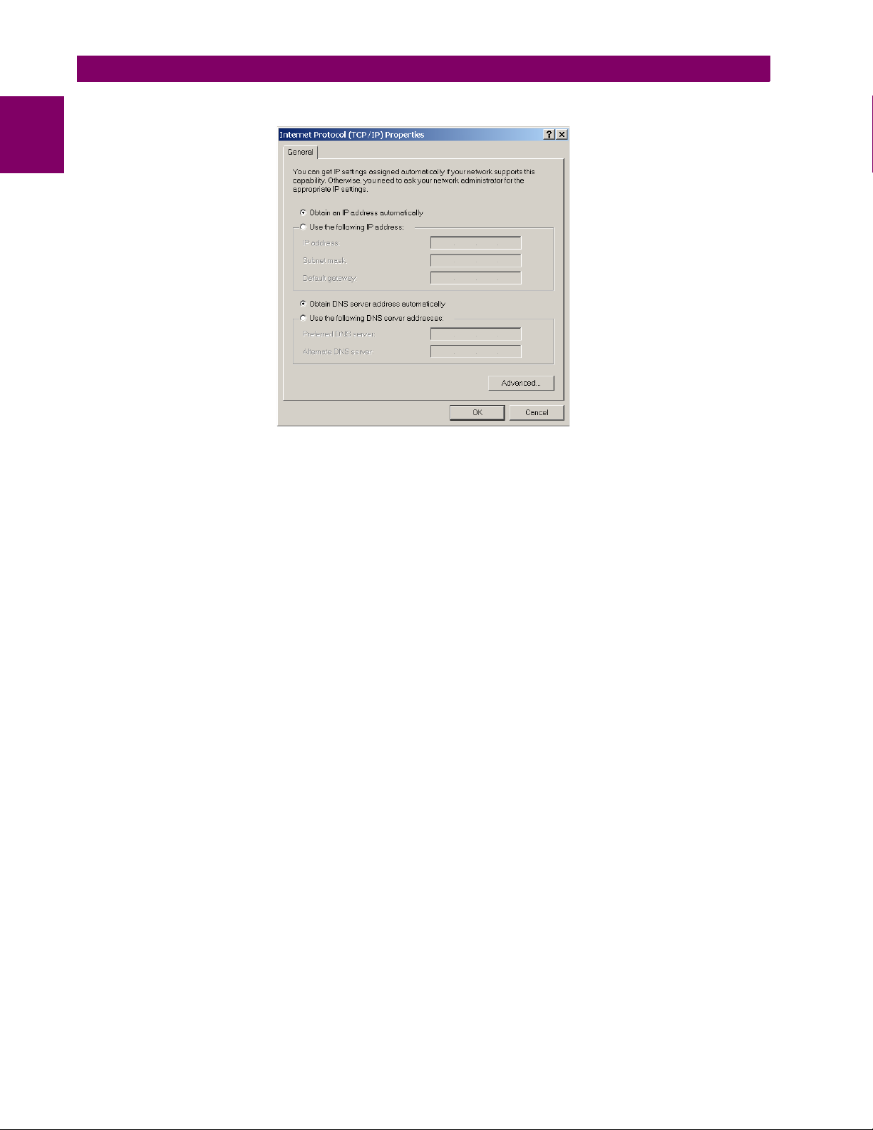
3. Select the Internet Protocol (TCP/IP) item from the list, and click the Properties button.
4. Click the “Use the following IP address” box.
5. Enter an IP address with the first three numbers the same as the IP address of the B90 relay and the last number
different (in this example, 1.1.1.2).
6. Enter a subnet mask equal to the one set in the B90 (in this example, 255.0.0.0).
7. Click the OK button to save the values.
Before continuing, test the Ethernet connection.
1. Open a Windows console window by selecting Start > Run from the Windows Start menu and typing “cmd”.
2. Type the following command, substituting the IP address of 1.1.1.1 with yours:
C:\WINNT>ping 1.1.1.1
3. If the connection is successful, the system returns four replies similar to the following:
Pinging 1.1.1.1 with 32 bytes of data:
Reply from 1.1.1.1: bytes=32 time<10ms TTL=255
Reply from 1.1.1.1: bytes=32 time<10ms TTL=255
Reply from 1.1.1.1: bytes=32 time<10ms TTL=255
Reply from 1.1.1.1: bytes=32 time<10ms TTL=255
Ping statistics for 1.1.1.1:
Packets: Sent = 4, Received = 4, Lost = 0 (0% loss),
Approximate round trip time in milliseconds:
Minimum = 0ms, Maximum = 0ms, Average = 0 ms
4. Note that the values for time and TTL vary depending on local network configuration.
5. If the following sequence of messages appears when entering the
C:\WINNT>ping 1.1.1.1 command:
1
GE Multilin B90 Low Impedance Bus Differential System 1-11
Page 20

1.3 ENERVISTA UR SETUP SOFTWARE 1 GETTING STARTED
Pinging 1.1.1.1 with 32 bytes of data:
1
Request timed out.
Request timed out.
Request timed out.
Request timed out.
Ping statistics for 1.1.1.1:
Packets: Sent = 4, Received = 0, Lost = 4 (100% loss),
Approximate round trip time in milliseconds:
Minimum = 0ms, Maximum = 0ms, Average = 0 ms
Pinging 1.1.1.1 with 32 bytes of data:
verify the physical connection between the B90 and the laptop computer, and double-check the programmed IP
address in the
PRODUCT SETUP COMMUNICATIONS NETWORK IP ADDRESS setting, then repeat step 2.
6. If the following sequence of messages appears when entering the
Pinging 1.1.1.1 with 32 bytes of data:
Hardware error.
Hardware error.
Hardware error.
Hardware error.
Ping statistics for 1.1.1.1:
Packets: Sent = 4, Received = 0, Lost = 4 (100% loss),
Approximate round trip time in milliseconds:
Minimum = 0ms, Maximum = 0ms, Average = 0 ms
Pinging 1.1.1.1 with 32 bytes of data:
verify the physical connection between the B90 and the laptop computer, and double-check the programmed IP
address in the
PRODUCT SETUP COMMUNICATIONS NETWORK IP ADDRESS setting, then repeat step 2.
7. If the following sequence of messages appears when entering the
Pinging 1.1.1.1 with 32 bytes of data:
Destination host unreachable.
Destination host unreachable.
Destination host unreachable.
Destination host unreachable.
Ping statistics for 1.1.1.1:
Packets: Sent = 4, Received = 0, Lost = 4 (100% loss),
Approximate round trip time in milliseconds:
Minimum = 0ms, Maximum = 0ms, Average = 0 ms
Pinging 1.1.1.1 with 32 bytes of data:
verify the IP address is programmed in the local computer by entering the ipconfig command in the command window.
C:\WINNT>ipconfig
Windows 2000 IP Configuration
Ethernet adapter <F4FE223E-5EB6-4BFB-9E34-1BD7BE7F59FF>:
Connection-specific DNS suffix. . :
IP Address. . . . . . . . . . . . : 0.0.0.0
Subnet Mask . . . . . . . . . . . : 0.0.0.0
Default Gateway . . . . . . . . . :
Ethernet adapter Local Area Connection:
Connection-specific DNS suffix . :
IP Address. . . . . . . . . . . . : 1.1.1.2
Subnet Mask . . . . . . . . . . . : 255.0.0.0
Default Gateway . . . . . . . . . :
C:\WINNT>
It can be necessary to restart the computer for the change in IP address to take effect (Windows 98 or NT).
C:\WINNT>ping 1.1.1.1 command:
C:\WINNT>ping 1.1.1.1 command:
1-12 B90 Low Impedance Bus Differential System GE Multilin
Page 21

1 GETTING STARTED 1.3 ENERVISTA UR SETUP SOFTWARE
Before using the Quick Connect feature through the Ethernet port, disable any configured proxy settings in Internet
Explorer.
1. Start the Internet Explorer software.
2. Select the Tools > Internet Options menu item and click the Connections tab.
3. Click on the LAN Settings button to open the following window.
4. Ensure that the “Use a proxy server for your LAN” box is not checked.
If this computer is used to connect to the Internet, re-enable any proxy server settings after the laptop has been disconnected from the B90 relay.
1. Start the Internet Explorer software.
2. Select the “UR” device from the EnerVista Launchpad to start EnerVista UR Setup.
3. Click the Quick Connect button to open the Quick Connect dialog box.
1
4. Select the Ethernet interface and enter the IP address assigned to the B90, then click the Connect button. The
EnerVista UR Setup software creates a site named “Quick Connect” with a corresponding device also named “Quick
Connect” and displays them at the upper-left of the screen.
5. Expand the sections to view data directly from the B90 device.
Each time the EnerVista UR Setup software is initialized, click the Quick Connect button to establish direct communications to the B90. This ensures that configuration of the EnerVista UR Setup software matches the B90 model number.
When direct communications with the B90 via Ethernet is complete, make the following changes:
1. From the Windows desktop, right-click the My Network Places icon and select Properties to open the network
connections window.
2. Right-click the Local Area Connection icon and select the Properties item.
3. Select the Internet Protocol (TCP/IP) item from the list provided and click the Properties button.
GE Multilin B90 Low Impedance Bus Differential System 1-13
Page 22
1.3 ENERVISTA UR SETUP SOFTWARE 1 GETTING STARTED
4. Set the computer to “Obtain a relay address automatically” as shown.
1
If this computer is used to connect to the Internet, re-enable any proxy server settings after the computer has been disconnected from the B90 relay.
AUTOMATIC DISCOVERY OF ETHERNET DEVICES
The EnerVista UR Setup software can automatically discover and communicate to all UR-series IEDs located on an Ethernet network.
Using the Quick Connect feature, a single click of the mouse triggers the software to automatically detect any UR-series
relays located on the network. The EnerVista UR Setup software then proceeds to configure all settings and order code
options in the Device Setup menu. This feature allows the user to identify and interrogate all UR-series devices at a location.
1-14 B90 Low Impedance Bus Differential System GE Multilin
Page 23

1 GETTING STARTED 1.3 ENERVISTA UR SETUP SOFTWARE
842743A3.CDR
Communications status indicators:
Green = OK
Red = No communications
UR icon = report is open
Quick action hot links
Expand the site list by double-clicking
or selecting the +/– box.
NOTE
1.3.5 CONNECTING TO THE B90 RELAY
1. Open the Display Properties window through the Site List tree as shown. The Display Properties window opens with a
status indicator on the lower left of the EnerVista UR Setup window.
1
2. If the status indicator is red, verify that the Ethernet network cable is properly connected to the Ethernet port on the
back of the relay and that the relay has been properly setup for communications (steps A and B earlier).
If a relay icon appears in place of the status indicator, than a report (such as an oscillography or event record) is open.
Close the report to re-display the green status indicator.
3. The Display Properties settings can now be edited, printed, or changed.
See chapter 4 in this manual or the EnerVista UR Setup Help File for information about the using the EnerVista UR
Setup software interface.
QUICK ACTION HOT LINKS
The EnerVista UR Setup software has several quick action buttons to provide instant access to several functions that are
often performed when using B90 relays. From the online window, users can select the relay to interrogate from a pull-down
window, then click the button for the action they want to perform. The following quick action functions are available:
• View the B90 event record
• View the last recorded oscillography record
• View the status of all B90 inputs and outputs
• View all of the B90 metering values
• View the B90 protection summary
• Generate a service report
GE Multilin B90 Low Impedance Bus Differential System 1-15
Page 24

1.4 UR HARDWARE 1 GETTING STARTED
1.4UR HARDWARE 1.4.1 MOUNTING AND WIRING
1
See Chapter 3: Hardware for mounting and wiring instructions.
1.4.2 COMMUNICATIONS
The EnerVista UR Setup software communicates to the relay via the faceplate RS232 port or the rear panel RS485 / Ethernet ports. To communicate via the faceplate RS232 port, a standard straight-through serial cable is used. The DB-9 male
end is connected to the relay and the DB-9 or DB-25 female end is connected to the computer COM2 port as described in
the CPU communications ports section of chapter 3.
Figure 1–7: RELAY COMMUNICATION OPTIONS
To communicate through the B90 rear RS485 port from a computer RS232 port, the GE Multilin RS232/RS485 converter
box is required. This device (catalog number F485) connects to the computer using a straight-through serial cable. A
shielded twisted-pair (20, 22, or 24 AWG) connects the F485 converter to the B90 rear communications port. The converter
terminals (+, –, GND) are connected to the B90 communication module (+, –, COM) terminals. See the CPU communica-
tions ports section in chapter 3 for details. The line is terminated with an R-C network (that is, 120 , 1 nF) as described in
the chapter 3.
1.4.3 FACEPLATE DISPLAY
All messages are displayed on a backlit liquid crystal display (LCD) to make them visible under poor lighting conditions.
While the keypad and display are not actively being used, the display defaults to user-defined messages. Any high-priority
event-driven message automatically overrides the default message and appears on the display.
1-16 B90 Low Impedance Bus Differential System GE Multilin
Page 25
1 GETTING STARTED 1.5 USING THE RELAY
1.5USING THE RELAY 1.5.1 FACEPLATE KEYPAD
Display messages are organized into pages under the following headings: actual values, settings, commands, and targets.
The MENU key navigates through these pages. Each heading page is divided further into logical subgroups.
The MESSAGE keys navigate through the subgroups. The VALUE keys increment or decrement numerical setting values
when in programming mode. These keys also scroll through alphanumeric values in the text edit mode. Alternatively, values can be entered with the numeric keypad.
The decimal key initiates and advances to the next character in text edit mode or enters a decimal point.
The HELP key can be pressed at any time for context-sensitive help messages.
The ENTER key stores altered setting values.
1.5.2 MENU NAVIGATION
Press the MENU key to select a header display page (top-level menu). The header title appears momentarily followed by a
header display page menu item. Each press of the MENU key advances through the following main heading pages:
• Actual values
• Settings
• Commands
• Targets
• User displays (when enabled)
1.5.3 MENU HIERARCHY
1
The setting and actual value messages are arranged hierarchically. The header display pages are indicated by double
scroll bar characters (), while sub-header pages are indicated by single scroll bar characters (). The header display
pages represent the highest level of the hierarchy and the sub-header display pages fall below this level. The MESSAGE
UP and DOWN keys move within a group of headers, sub-headers, setting values, or actual values. Continually pressing
the MESSAGE RIGHT key from a header display displays specific information for the header category. Conversely, continually pressing the MESSAGE LEFT key from a setting value or actual value display returns to the header display.
HIGHEST LEVEL LOWEST LEVEL (SETTING
VALUE )
SETTINGS
PRODUCT SETUP
SETTINGS
SYSTEM SETUP
The relay is in the default “Not Programmed” state when it leaves the factory. When powered up successfully, the Trouble
LED is on and the In Service LED off. The relay in the “Not Programmed” state blocks signaling of any output relay. These
conditions remain until the relay is explicitly put in the “Programmed” state.
Select the menu message
RELAY SETTINGS:
Not Programmed
SETTINGS PRODUCT SETUP INSTALLATION RELAY SETTINGS
PASSWORD
SECURITY
ACCESS LEVEL:
Restricted
1.5.4 RELAY ACTIVATION
1. To put the relay in the “Programmed” state, press either of the VALUE keys once and then press ENTER. The
faceplate Trouble LED turns off and the In Service LED turns on.
GE Multilin B90 Low Impedance Bus Differential System 1-17
Page 26

1.5 USING THE RELAY 1 GETTING STARTED
NOTE
The settings for the relay can be programmed manually (see Chapter 5) via the faceplate keypad or remotely via the
EnerVista UR Setup software (see the EnerVista UR Setup help file).
1
1.5.5 RELAY PASSWORDS
It is recommended that passwords be set for each security level and assigned to specific personnel. There are two user
security access levels, COMMAND and SETTING.
1. COMMAND
The COMMAND access level restricts the user from making any settings changes, but allows the user to perform the following operations:
• Change state of virtual inputs
• Clear event records
• Clear oscillography records
• Operate user-programmable pushbuttons
2. SETTING
The SETTING access level allows the user to make any changes to any of the setting values.
See the Changing Settings section in Chapter 4 for complete instructions on setting security-level passwords.
1.5.6 FLEXLOGIC™ CUSTOMIZATION
FlexLogic equation editing is required for setting user-defined logic for customizing the relay operations. See the FlexLogic
section in Chapter 5.
1-18 B90 Low Impedance Bus Differential System GE Multilin
Page 27

1 GETTING STARTED 1.5 USING THE RELAY
1.5.7 COMMISSIONING
The B90 requires minimal maintenance after it is commissioned into service. Since the B90 is a microprocessor-based
relay, its characteristics do not change over time. As such, no further functional tests are required.
The B90 performs a number of continual self-tests and takes the necessary action in case of any major errors (see the
Relay Self-tests section in chapter 7). However, it is recommended that B90 maintenance be scheduled with other system
maintenance. This maintenance can involve in-service, out-of-service, or unscheduled maintenance.
In-service maintenance:
1. Visual verification of the analog values integrity, such as voltage and current (in comparison to other devices on the
corresponding system).
2. Visual verification of active alarms, relay display messages, and LED indications.
3. LED test.
4. Visual inspection for any damage, corrosion, dust, or loose wires.
5. Event recorder file download with further events analysis.
Out-of-service maintenance:
1. Check wiring connections for firmness.
2. Analog values (currents, voltages, RTDs, analog inputs) injection test and metering accuracy verification. Calibrated
test equipment is required.
3. Protection elements setting verification (analog values injection or visual verification of setting file entries against relay
settings schedule).
4. Contact inputs and outputs verification. This test can be conducted by direct change of state forcing or as part of the
system functional testing.
5. Visual inspection for any damage, corrosion, or dust.
6. Event recorder file download with further events analysis.
7. LED Test and pushbutton continuity check.
Unscheduled maintenance, such as a disturbance causing system interruption:
1. View the event recorder and oscillography or fault report for correct operation of inputs, outputs, and elements.
If it is concluded that the relay or one of its modules is of concern, contact GE Multilin for service.
1
GE Multilin B90 Low Impedance Bus Differential System 1-19
Page 28

1
1.5 USING THE RELAY 1 GETTING STARTED
1-20 B90 Low Impedance Bus Differential System GE Multilin
Page 29

2 PRODUCT DESCRIPTION 2.1 INTRODUCTION
2 PRODUCT DESCRIPTION 2.1INTRODUCTION 2.1.1 OVERVIEW
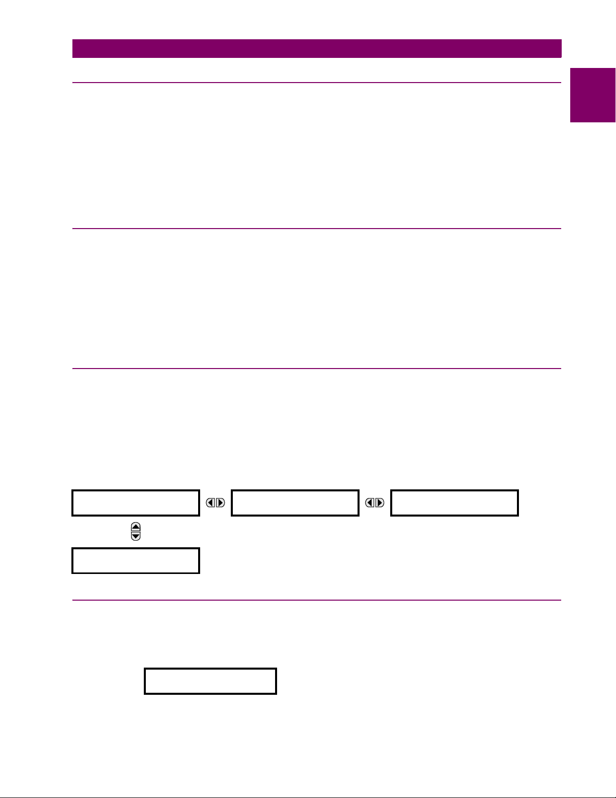
The B90 Low Impedance Bus Differential System is a microprocessor-based architecture that provides protection and
metering for busbars with up to 24 feeders. The B90 protection system is a centralized architecture built on three, four, or
more B90 IEDs as per requirements of a particular application. Each IED of the B90 system is a full-featured B90 and as
such can be accessed and programmed individually. Protection and supervisory functions of the B90 include:
• Multi-zone differential protection with both restrained (percent, biased) and unrestrained (unbiased, instantaneous)
functions incorporated. Differential protection is fast (typical response time: ¾ of a power cycle; maximum response
time: 1 power cycle) and secure. Security is achieved by using fast and reliable CT saturation detection algorithm and
a second, phase comparison operating principle.
• Check-zone functionality is provided by programming one of the differential zones to enclose the entire bus.
• Dynamic bus replica functionality and multi-zone protection allowing application of the B90 to multi-section re-configu-
rable busbars.
• Isolator monitoring feature monitors up to 48 isolators from a single B90 IED.
• End fault protection (dead zone protection) is provided for up to 24 breakers.
• CT trouble monitoring function is provided for each zone of differential protection.
• Breaker fail function is provided for up to 24 breakers.
• An instantaneous overcurrent function is available per each current input of the B90 system.
• A time overcurrent function is available per each current input of the B90 system for backup protection.
• An undervoltage function is provided per each voltage input of the B90 system for supervision purposes.
Voltage and current metering is built into the relay as a standard feature. Current parameters are available as total waveform RMS magnitude, or as fundamental frequency only RMS magnitude and angle (phasor).
Diagnostic features include a sequence of records capable of storing 1024 time-tagged events per each B90 IED and oscillography that is user-programmable as to sampling rate (up to 64 samples per cycle), content, writing mode, and record
length. The internal clock used for time-tagging can be synchronized with an IRIG-B signal or via the SNTP protocol over
the Ethernet port. This precise time stamping allows the sequence of events to be determined between the B90 IEDs and
throughout the system. Events can also be programmed (via FlexLogic™ equations) to trigger oscillography data capture
which may be set to record the measured parameters before and after the event for viewing on a personal computer (PC).
These tools significantly reduce troubleshooting time and simplify report generation in the event of a system fault.
A faceplate RS232 port may be used to connect to a PC for the programming of settings and the monitoring of actual values. A variety of communications modules are available. Two rear RS485 ports allow independent access by operating and
engineering staff. All serial ports use the Modbus RTU protocol. The RS485 ports may be connected to system computers
with baud rates up to 115.2 kbps. The RS232 port has a fixed baud rate of 19.2 kbps. The 100Base-FX Ethernet interface
provides fast, reliable communications in noisy environments. The Ethernet port supports IEC 61850, Modbus/TCP, and
TFTP protocols, PTP (according to IEEE Std. 1588-2008 or IEC 61588), and allows access to the relay via any standard
web browser (B90 web pages). The IEC 60870-5-104 protocol is supported on the Ethernet port, and DNP 3.0 and IEC
60870-5-104 cannot be enabled at the same time.
The B90 IEDs use flash memory technology which allows field upgrading as new features are added. The following Single
line diagram illustrates the relay functionality using ANSI (American National Standards Institute) device numbers.
The available zones of differential protection and their size (maximum number of inputs) are optional and
controlled by the software option portion of the order code. The breaker failure function is also optional.
See the ordering section for detailed information on the maximum number of zones and inputs for a given
model. In addition, different applications may require differing numbers of B90 IEDs with different hardware configurations.
2
Table 2–1: ANSI DEVICE NUMBERS AND FUNCTIONS
DEVICE FUNCTION DEVICE FUNCTION
27 Undervoltage 50/87 Unrestrained bus differential
50 Instantaneous overcurrent 51 Time overcurrent
50/74 CT trouble 50BP Breaker failure
GE Multilin B90 Low Impedance Bus Differential System 2-1
Page 30

2
2.1 INTRODUCTION 2 PRODUCT DESCRIPTION
Figure 2–1: SINGLE LINE DIAGRAM
Table 2–2: OTHER DEVICE FUNCTIONS
FUNCTION FUNCTION
Contact inputs (up to 96 per IED) Modbus user map
Contact outputs (up to 64 per IED) Non-volatile latches
Control pushbuttons Non-volatile selector switch
CyberSentry™ security Oscillography
Digital elements (48 per IED) Setting groups (6)
Direct inputs and outputs (96) Time synchronization over IRIG-B or IEEE 1588
DNP 3.0 or IEC 60870-5-104 communications Time synchronization over SNTP
Dynamic bus replica User definable displays
End fault protection User-programmable fault reports
Event recorder User-programmable LEDs
FlexLogic™ equations User-programmable pushbuttons
IEC 61850 communications (optional) User-programmable self-tests
Metering: current, voltage, frequency Virtual inputs (64 per IED)
Modbus communications Virtual outputs (96 per IED)
2-2 B90 Low Impedance Bus Differential System GE Multilin
Page 31
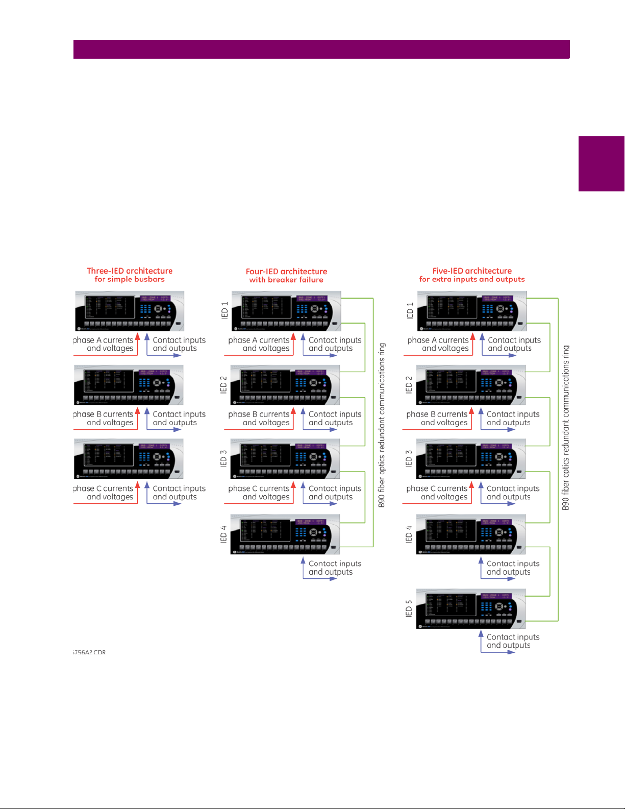
2 PRODUCT DESCRIPTION 2.1 INTRODUCTION
The main protection functions of the B90 are provided on a per-phase basis. The AC signals of a given phase, both currents and voltages, are connected and processed by a single IED. These IEDs provide for all the protection and monitoring
functions that require the AC information. Also these IEDs provide for certain input/output capability (up to a maximum of 48
inputs or 18 outputs per IED).
The simplest B90 configuration for non-re-configurable busbars without Breaker Fail protection consists of three B90 IEDs.
The Breaker Fail and Isolator Monitoring function for dynamic bus replica require a separate IED, and thus a four-IED B90
architecture. These are shown in the figure below.
In any B90 configuration, the IEDs are capable of exchanging digital states (FlexLogic™ operands) in a fast and reliable
way over a dedicated B90 fiber connection. The B90 communication capability allows the user to distribute input and output
contacts freely in various IEDs. Also, the communications facilitates Breaker Fail and Isolator Monitoring.
If more input/output capabilities are required, a fifth B90 IED can be included into the B90 communications ring as shown
below.
The EnerVista UR Setup software is used to control the B90 IEDs. Each IED is configured and accessed individually. Functionality is provided to perform certain operations on all the B90 IEDs simultaneously.
2
Figure 2–2: THREE-, FOUR-, AND FIVE-IED B90 ARCHITECTURE
GE Multilin B90 Low Impedance Bus Differential System 2-3
Page 32
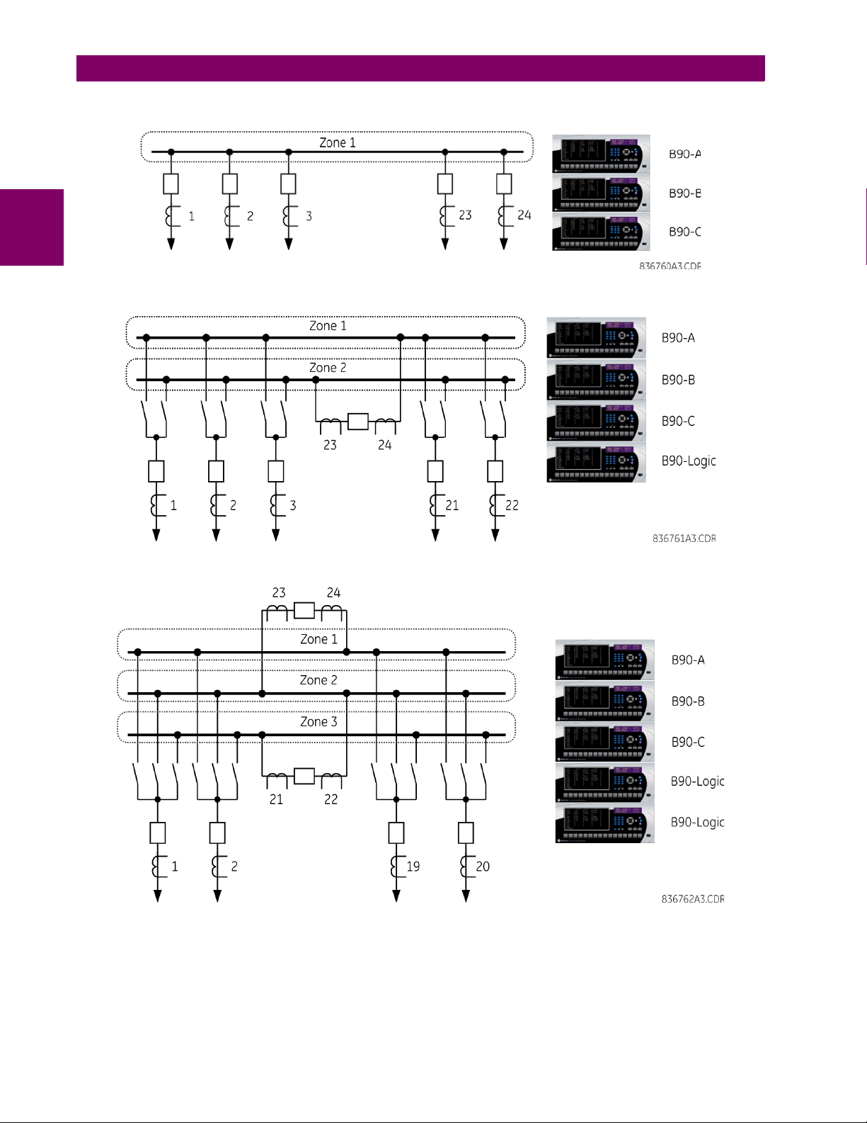
2.1 INTRODUCTION 2 PRODUCT DESCRIPTION
The following figures show sample applications of the B90 protection system:
2
Figure 2–3: SINGLE BUS
Figure 2–4: DOUBLE BUS
Figure 2–5: TRIPLE BUS
2-4 B90 Low Impedance Bus Differential System GE Multilin
Page 33
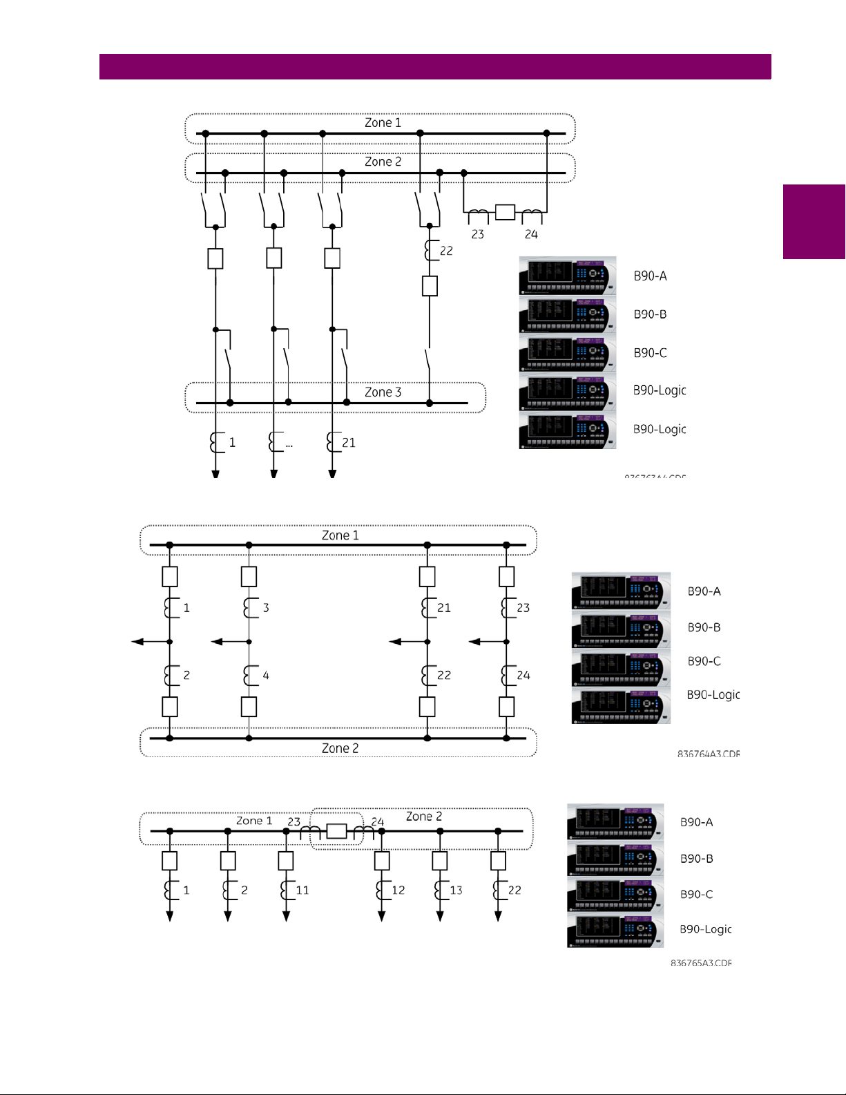
2 PRODUCT DESCRIPTION 2.1 INTRODUCTION
2
Figure 2–6: DOUBLE BUS WITH TRANSFER
Figure 2–7: BREAKER-AND-A-HALF CONFIGURATION BUS
Figure 2–8: SINGLE BUS WITH A SINGLE TIE BREAKER
GE Multilin B90 Low Impedance Bus Differential System 2-5
Page 34
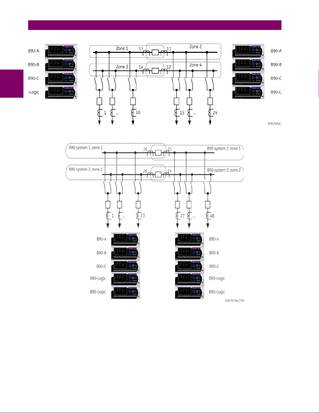
2
2.1 INTRODUCTION 2 PRODUCT DESCRIPTION
Figure 2–9: DOUBLE BUS WITH ONE TIE BREAKER ON EACH BUS
Figure 2–10: APPLICATION INVOLVING TWO OR MORE B90 SYSTEMS
2-6 B90 Low Impedance Bus Differential System GE Multilin
Page 35
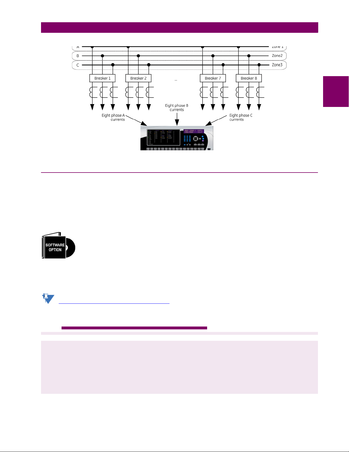
2 PRODUCT DESCRIPTION 2.1 INTRODUCTION
NOTE
Figure 2–11: APPLICATION TO 8-FEEDER BUSBARS
2.1.2 ORDERING
A B90 protection system consists of several UR-series B90 IEDs as per user needs and system configuration. At least
three IEDs are required to provide differential and other protection functions for phases A, B, and C of the busbar. The
fourth IED is required for breaker failure functionality and isolator status monitoring as well as extra input and output capability. A fifth IED is sometimes required for additional input and output capability.
Before ordering the B90 system, an analysis of the required protection and monitoring functions is required. Please refer to
the UR overview section in chapter 1 for details of the B90 architecture. Also, detailed analyses of required AC inputs and
input/output contacts must be performed to select appropriate hardware configurations for each of the B90's IEDs.
The B90 Low Impedance Bus Differential System is provided with an option of protecting either 8, 16, or
24-feeder busbars. When ordered as an eight-feeder protection system, the B90 is configurable for up to
eight-input bus differential, regardless of the number of physical current inputs available in the B90 IEDs.
The ordering convention for each of the B90 IEDs is described below.
2
The relay is available as a 19-inch rack horizontal mount unit and consists of the following modules: power supply, CPU,
CTs and VTs, digital inputs and outputs, and inter-relay communications. Each of these modules can be supplied in a number of configurations specified at the time of ordering. The information required to completely specify the relay is provided in
the following tables (see chapter 3 for full details of relay modules).
Order codes are subject to change without notice. See the GE Multilin ordering page at
http://www.gedigitalenergy.com/multilin/order.htm
for the latest B90 ordering options.
Table 2–3: B90 ORDER CODES
BASE B90 | | | | | | | | | | | | | Base Unit
CPU T | | | | | | | | | | | | RS485 with 3 100Base-FX Ethernet, multimode, SFP with LC
BREAKER
FAILURE
SOFTWARE OPTIONS A | | | | | | | | | | | CyberSentry Lvl 1
B90 - * * * - * * * - F ** - H ** - L ** - N ** - S ** - U ** - W/ X ** Full Size Horizontal Mount
0 | | | | | | | | | | | No breaker failure option
1 | | | | | | | | | | | With breaker failure option
B | | | | | | | | | | | IEEE 1588
D | | | | | | | | | | | IEEE 1588 and Cybersentry Lvl 1
0 | | | | | | | | | | Four-zone 8-feeder bus protection
1 | | | | | | | | | | Four-zone 16-feeder bus protection
2 | | | | | | | | | | Four-zone 24-feeder bus protection
3 | | | | | | | | | | Single-zone 24-feeder bus protection
4 | | | | | | | | | | Four-zone 8-feeder bus protection with IE C 61850; not available for 9E CPUs
5 | | | | | | | | | | Four-zone 16-feeder bus protection with IE C 61850; not available for 9E CPUs
6 | | | | | | | | | | Four-zone 24-feeder bus protection with IE C 61850; not available for 9E CPUs
7 | | | | | | | | | | Single-zone 24-feeder bus protection with IE C 61850; N/A for 9E CPUs
8 | | | | | | | | | | Four-zone 8-feeder bus protection and breaker failure
9 | | | | | | | | | | Four-zone 16-feeder bus protection and breaker failure
A | | | | | | | | | | Four-zone 24-feeder bus protection and breaker failure
B | | | | | | | | | | One-zone 24-feeder bus protection and breaker failure
C | | | | | | | | | | Four- zone 8-feeder bus protection, IEC 61850, and breaker failure
D | | | | | | | | | | Four- zone 16-feeder bus protection, IEC 61850, and breaker failure
E | | | | | | | | | | Four-zone 24-feeder bus protection, IEC 61850, and breaker failure
F | | | | | | | | | | One-zone 24-feeder bus protection, IEC 61850, and breaker failure
GE Multilin B90 Low Impedance Bus Differential System 2-7
Page 36

2.1 INTRODUCTION 2 PRODUCT DESCRIPTION
Table 2–3: B90 ORDER CODES
MOUNTING H | | | | | | | | | Horizontal (19” rack)
FACEPLATE/DISPLAY C | | | | | | | | English display
2
POWER SUPPLY
(redundant power supply must be same
type as main power supply)
CT/VT MODULES XX | XX | XX | | None
DIGITAL INPUTS/OUTPUTS XX XX XX XX XX XX | No Module
INTER-RELAY
COMMUNICATIONS
(select a maximum of 1 per unit)
A | | | | | | | | | Horizontal (19” rack) with harsh-environmental coating
D | | | | | | | | French display
R | | | | | | | | Russian display
A | | | | | | | | Chinese display
P | | | | | | | | English display with 4 small and 12 large programmable pushbuttons
G | | | | | | | | French display with 4 small and 12 large programmable pushbuttons
S | | | | | | | | Russian display with 4 small and 12 large progr ammable pushbuttons
B | | | | | | | | Chinese display with 4 small and 12 large programmable pushbuttons
K | | | | | | | | Enhanced front panel with English display
M | | | | | | | | Enhanced front panel with French display
Q | | | | | | | | Enhanced front panel with Russian display
U | | | | | | | | Enhanced front panel with Chinese display
L | | | | | | | | Enhanced front panel with English display and user-programmable pushbuttons
N | | | | | | | | Enhanced front panel with French display and user-programmable pushbuttons
T | | | | | | | | Enhanced front panel with Russian display and user-programmable pushbuttons
V | | | | | | | | Enhanced front panel with Chinese display and user-programmable pushbuttons
W | | | | | | | | Enhanced front panel with Turkish display
Y | | | | | | | | Enhanced front panel with Turkish display and user-programmable pushbuttons
H | | | | | | | 125 / 250 V AC/DC
H | | | | | | RH 125 / 250 V AC/DC with redundant 125 / 250 V AC/DC power supply
L | | | | | | | 24 to 48 V (DC only)
L | | | | | | RL 24 to 48 V (DC only) with redundant 24 to 48 V DC power supply
8F | 8F | 8F | | Standard 4CT/4VT
8H | 8H | 8H | | Standard 8CT
8K | 8K | 8K | | Standard 7CT/1VT
8L | 8L | 8L | | Standard 4CT/4VT with enhanced diagnostics
8N | 8N | 8N | | Standard 8CT with enhanced diagnostics
8S | 8S | 8S | | Standard 7CT/1VT with enhanced diagnostics
4A 4A 4A 4A 4A 4A | 4 Solid state (no monitoring) MOSFET outputs
4B 4B 4B 4B 4B 4B | 4 Solid state (voltage with optional current) MOSFET outputs
4C 4C 4C 4C 4C 4C | 4 Solid state (current with option al voltage) MOSFET outputs
4D 4D 4D 4D 4D 4D | 16 Digital inputs with auto-burnish (maximum 3 modules within a case)
4L 4L 4L 4L 4L 4L | 14 Form-A (no monitoring) latchable outputs
6A 6A 6A 6A 6A 6A | 2 Form-A (voltage with optional current) and 2 Form-C outputs, 8 digital inputs
6B 6B 6B 6B 6B 6B | 2 Form-A (voltage with optional current) and 4 Form-C outputs, 4 digital inputs
6C 6C 6C 6C 6C 6C | 8 Form-C outputs
6D 6D 6D 6D 6D 6D | 16 digital inputs
6E 6E 6E 6E 6E 6E | 4 Form-C outputs, 8 digital inputs
6F 6F 6F 6F 6F 6F | 8 Fast Form-C outputs
6G 6G 6G 6G 6G 6G | 4 Form-A (voltage with optional current) outputs, 8 digital inputs
6H 6H 6H 6H 6H 6H | 6 Form-A (voltage with optional curr ent) outputs, 4 digital inputs
6K 6K 6K 6K 6K 6K | 4 Form-C and 4 Fast Form-C outputs
6L 6L 6L 6L 6L 6L | 2 Form-A (current with optional voltage) and 2 Form- C outputs, 8 digital inputs
6M 6M 6M 6M 6M 6M | 2 Form-A (current with optional voltage) and 4 Form-C outputs, 4 digital inputs
6N 6N 6N 6N 6N 6N | 4 Form-A (current with o ptional voltage) outputs, 8 digital inputs
6P 6P 6P 6P 6P 6P | 6 Form-A (current with optional voltage) outputs, 4 digital inputs
6R 6R 6R 6R 6R 6R | 2 Form-A (no monitoring) and 2 Form-C outputs, 8 digital inputs
6S 6S 6S 6S 6S 6S | 2 Form-A (no monitoring) and 4 Form-C outputs, 4 digital inputs
6T 6T 6T 6T 6T 6T | 4 Form-A (no monitoring) outputs, 8 digital inputs
6U 6U 6U 6U 6U 6U | 6 Form-A (no monitoring) outpu ts, 4 digital inputs
67 67 67 67 67 67 | 8 Form-A (no monitoring) outputs
XX XX No Module
2A 2A C37.94SM, 1300nm single-mode, ELED, 1 channel single-mode
2B 2B C37.94SM, 1300nm single-mode, ELED, 2 channel single-mode
2E 2E Bi-phase, single channel
2F 2F Bi-phase, dual channel
2G 2G IEEE C37.94, 820 nm, 128 kbps, multimode, LED, 1 Channel
2H 2H IEEE C37.94, 820 nm, 128 kbps, multimode, LED, 2 Channels
72 72 1550 nm, single-mode, LASER, 1 Channel
73 73 1550 nm, single-mode, LASER, 2 Channel
74 74 Channel 1 - RS422; Channel 2 - 1550 nm, single-mode, LASER
75 75 Channel 1 - G.703; Channel 2 - 1550 nm, Single-mode LASER
76 76 IEEE C37.94, 820 nm, 64 kbps, multimode, LED, 1 Channel
77 77 IEEE C37.94, 820 nm, 64 kbps, multimode, LED, 2 Channels
7A 7A 820 nm, multi-mode, LED, 1 Channel
7B 7B 1300 nm, multi-mode, LED, 1 Channel
7C 7C 1300 nm, single-mode, ELE D, 1 Channel
7D 7D 1300 nm, single-mode, LAS ER, 1 Channel
7E 7E Channel 1 - G.703; Channel 2 - 820 nm, multi-mode
7F 7F Channel 1 - G.703; Channel 2 - 1300 nm, multi-mode
7G 7G Channel 1 - G.703; Channel 2 - 1300 nm, single-mode ELED
7H 7H 820 nm, multi-mode, LED , 2 Channels
7I 7I 1300 nm, multi-mode, LED, 2 Channels
7J 7J 1300 nm, single-mode, ELED, 2 Channels
7K 7K 1300 nm, single-mode, LASER, 2 Channels
7L 7L Channel 1 - RS422; Channel 2 - 820 nm, multi-mode, LED
7M 7M Channel 1 - RS422; Channel 2 - 1300 nm, multi-mode, LED
7M 7M Channel 1 - RS422; Channel 2 - 1300 nm, single-mode, ELED
7N 7N Channel 1 - RS422; Channel 2 - 1300 nm, single-mode, ELED
7P 7P Channel 1 - RS422; Channel 2 - 1300 nm, single-mode, LASER
7Q 7Q Channel 1 - G.703; Channel 2 - 1300 nm, single-mode LASER
7R 7R G.703, 1 Channel
7S 7S G.703, 2 Channels
7T 7T RS422, 1 Channel
7W 7W RS422, 2 Channels
2-8 B90 Low Impedance Bus Differential System GE Multilin
Page 37

2 PRODUCT DESCRIPTION 2.1 INTRODUCTION
NOTE
NOTE
2.1.3 REPLACEMENT MODULES
Replacement modules can be ordered separately. When ordering a replacement CPU module or faceplate, provide the
serial number of your existing unit.
Not all replacement modules may be applicable to the B90 relay. Only the modules specified in the order codes are
available as replacement modules.
Replacement module codes are subject to change without notice. See the GE Multilin ordering page at
http://www.gedigitalenergy.com/multilin/order.htm
for the latest B90 ordering options.
The replacement module order codes for the horizontal mount units are shown below.
2
Table 2–4: ORDER CODES FOR REPLACEMENT MODULES, HORIZONTAL UNITS
POWER SUPPLY (redundant supply only available in
horizontal units; must be same type as main supply)
CPU | T | RS485 with 3 100Base- FX Ethernet, multimode, SFP with LC
FACEPLATE/DISPLAY | 3C | Horizontal faceplate with keypad and English display
DIGITAL INPUTS AND OUTPUTS | 4A | 4 Solid-State (no monitoring) MOSFET outputs
CT/VT
MODULES
(NOT AVAILABLE FOR THE C30)
INTER-RELAY COMMUNICATIONS | 2A | C37.94SM, 1300nm single-mode, ELED, 1 channel single-mode
UR - ** - *
| RH H | Redundant 125 / 250 V AC/DC
| RL H | Redundant 24 to 48 V (DC only)
| 3D | Horizontal faceplate with keypad and French display
| 3R | Horizontal faceplate with keypad and Russian display
| 3A | Horizontal faceplate with keypad and Chinese display
| 3P | Horizontal faceplate with keypad, user-programmable pushbuttons, and English display
| 3G | Horizontal faceplate with keypad, user-programmable pushbuttons, and French display
| 3S | Horizontal faceplate with keypad, user-programmable pushbuttons, and Russian display
| 3B | Horizontal faceplate with keypad, user-programmable pushbuttons, and Chinese display
| 3K | Enhanced front panel with English display
| 3M | Enhanced fro nt panel with French display
| 3Q | Enhanced front panel with Russian display
| 3U | Enhanced front panel with Chinese display
| 3L | Enhanced front panel with English display and user-programmable pushbuttons
| 3N | Enhanced front panel with French display and user-programmable pushbuttons
| 3T | Enhanced front panel with Russian display and user- programmable pushbuttons
| 3V | Enhanced front panel with Chinese display and user-programmable pushbuttons
| 3W | Enhanced front panel with Turkish display
| 3Y | Enhanced front panel with Turkish display and user-programmable pushbuttons
| 4B | 4 Solid-State (voltage with optional current) MOSFET outputs
| 4C | 4 Solid-State (current with optional voltage) MOSFET outputs
| 4D | 16 digital inputs with Auto-Burnishing
| 4L | 14 Form-A (no monitoring) Latching outputs
| 67 | 8 Form-A (no monitoring) outputs
| 6A | 2 Form-A (voltage with optional current) and 2 Form-C outputs, 8 digital inputs
| 6B | 2 Form-A (voltage with optional current) and 4 Form-C outputs, 4 digital inputs
| 6C | 8 Form-C outputs
| 6D | 16 digital inputs
| 6E | 4 Form-C outputs, 8 digital inputs
| 6F | 8 Fast Form-C outputs
| 6G | 4 Form-A (voltage with optional current) outputs, 8 digital inputs
| 6H | 6 Form-A (voltage with optional current) outputs, 4 digital inputs
| 6K | 4 Form-C and 4 Fast Form-C outpu ts
| 6L | 2 Form-A (current with optional voltage) and 2 Form-C outputs, 8 digital inputs
| 6M | 2 Form-A (current with optional voltage) and 4 Form-C outputs, 4 digital inputs
| 6N | 4 Form-A (current with optional voltage) outputs, 8 digital inputs
| 6P | 6 Form-A (current with optional voltage) out puts, 4 digital inputs
| 6R | 2 Form-A (no monitoring) and 2 Form-C outputs, 8 digital inputs
| 6S | 2 Form-A (no monitoring) and 4 For m-C outputs, 4 digital inputs
| 6T | 4 Form-A (no monitoring) outputs, 8 digital inputs
| 6U | 6 Form-A (no monitoring) outputs, 4 digital inputs
| 6V | 2 Form-A outputs, 1 Form-C output, 2 Form- A (no monitoring) latching outputs, 8 digital inputs
| 8F | Standard 4CT/4VT
| 8G | Sensitive Ground 4CT/4VT
| 8H | Standard 8CT
| 8K | Standard 7CT/1VT
| 8L | Standard 4CT/4VT wit h enhanced diagnostics
| 8N | Standard 8CT with enhanced diagnostics
| 2B | C37.94SM, 1300nm single-mode, ELED, 2 channel single -mode
| 2E | Bi-phase, single channel
| 2F | Bi-phase, dual channel
| 2G | IEEE C37.94, 820 nm, 128 kbps, multimode, LED, 1 Channel
| 2H | IEEE C37.94, 820 nm, 128 kbps, multimode, LED, 2 Channels
| 72 | 1550 nm, single-mode, LASER, 1 Channel
| 73 | 1550 nm, single-mode, LASER, 2 Channel
| 74 | Channel 1 - RS422; Channel 2 - 1550 nm, single-mode, LASER
| 75 | Channel 1 - G.703; Channel 2 - 1550 nm, Single-mode LASER
| 76 | IEEE C37.94, 820 nm, multimode, LED, 1 Channel
| 77 | IEEE C37.94, 820 nm, multimode, LED, 2 Channels
| 7A | 820 nm, multi-mode, LED, 1 Channel
| 7B | 1300 nm, multi-mode, LED, 1 Channel
| 7C | 1300 nm, single-mode, ELED, 1 Channel
| 7D | 1300 nm, single-mode, LASER, 1 Channel
| 7E | Channel 1 - G.703; Channel 2 - 820 nm, multi-mode
| 7F | Chan nel 1 - G.703; Channel 2 - 1300 nm, multi-mode
| 7G | Channel 1 - G.703; Channel 2 - 1300 nm, single-mode ELED
| 7H | 820 nm, multi-mode, LED, 2 Channels
| 7I | 1300 nm, multi-mode, LED, 2 Channels
| 7J | 1300 nm, single-mode, ELED, 2 Channels
| 7K | 1300 nm, single-mode, LASER, 2 Channels
| 7L | Channel 1 - RS422; Channel 2 - 820 nm, multi-mode, LED
| 7M | Channel 1 - RS422; Channel 2 - 1300 nm, multi-mode, LED
| 7N | Channel 1 - RS422; Channel 2 - 1300 nm, single-mode, ELED
| 7P | Channel 1 - RS422; Channel 2 - 1300 nm, single- mode, LASER
| 7Q | Channel 1 - G.703; Channel 2 - 1300 nm, single-mode LASER
| 7R | G.703, 1 Channel
| 7S | G.703, 2 Channels
| 7T | RS422, 1 Channel
| 7W | RS422, 2 Channels
GE Multilin B90 Low Impedance Bus Differential System 2-9
Page 38

2.2 SPECIFICATIONS 2 PRODUCT DESCRIPTION
NOTE
2.2SPECIFICATIONS
SPECIFICATIONS ARE SUBJECT TO CHANGE WITHOUT NOTICE
2.2.1 PROTECTION ELEMENTS
The operating times below include the activation time of a trip rated form-A output contact unless otherwise indicated. FlexLogic operands of a given element are 4 ms faster. Take this into account when using FlexLogic to inter-
2
connect with other protection or control elements of the relay, building FlexLogic equations, or interfacing with other
IEDs or power system devices via communications or different output contacts.
BUS DIFFERENTIAL (87B)
Pickup level: 0.050 to 2.000 pu in steps of 0.001
Low slope: 15 to 100% in steps of 1
High slope: 50 to 100% in steps of 1
Low breakpoint: 1.00 to 30.00 pu in steps of 0.01
High breakpoint: 1.00 to 30.00 pu in steps of 0.01
High set level: 0.10 to 99.99 pu in steps of 0.01
Dropout level: 97 to 98% of pickup
Level accuracy:
0.1 to 2.0 CT rating: ±0.5% of reading or ±1% of rated (whichever is greater)
>2.0 CT rating ±1.5% of reading
Operating time: one power system cycle (typical)
Number of zones: 1 or 4 (option)
Max number of inputs: 8, 16, or 24 (option)
CT TROUBLE
Responding to: Differential current
Pickup level: 0.020 to 2.000 pu in steps of 0.001
Pickup delay: 1.0 to 60.0 sec. in steps of 0.1
Time accuracy: ±3% or ±40 ms, whichever is greater
Availability: one per zone of protection
ISOLATOR MONITORING
Responding to: Both normally-open and normally-closed auxiliary contacts
Asserting: Isolator Position, Isolator Alarm, Block Switching
Alarm pickup delay: 0.00 to 10.00 s in steps of 0.05
Time accuracy: ±3% or ±40 ms, whichever is greater
TIME OVERCURRENT
Pickup level: 0.000 to 30.000 pu in steps of 0.001
Dropout level: 97 to 98% of pickup
Level accuracy:
0.1 to 2.0 CT 0.5% of reading or 1% of nominal (whichever is greater)
above 2.0 CT 1.5% of reading
Curve shapes: IEEE Moderately/Very/Extremely Inverse; IEC (and BS) A/B/C and Short Inverse; GE IAC Inverse, Short/Very/
Extremely Inverse; I
TD multiplier: 0.00 to 600.00 in steps of 0.01
Reset type: Instantaneous or Timed (per IEEE)
Time accuracy: ±3% or ±40 ms, whichever is greater
2
t; FlexCurves™ (programmable); Definite Time (0.01 s base curve)
INSTANTANEOUS OVERCURRENT
Pickup level: 0.000 to 30.000 pu in steps of 0.001
Dropout level: 97 to 98% of pickup
Level accuracy:
0.1 to 2.0 CT 0.5% of reading or 1% of nominal (whichever is greater)
above 2.0 CT 1.5% of reading
Pickup delay: 0 to 65.535 s in steps of 0.001
Reset delay: 0 to 65.535 s in steps of 0.001
2-10 B90 Low Impedance Bus Differential System GE Multilin
Page 39

2 PRODUCT DESCRIPTION 2.2 SPECIFICATIONS
Time accuracy: ±3% or ±4 ms, whichever is greater
Operate time: 16 ms at 60 Hz
UNDERVOLTAGE
Pickup level: 0.000 to 3.000 pu in steps of 0.001
Dropout level: 102 to 103% of pickup
Level accuracy: ±0.5% of reading from 10 to 208 V
Pickup delay: 0 to 65.535 s in steps of 0.001
Reset delay: 0 to 65.535 s in steps of 0.001
Time accuracy: ±3% or ±4 ms, whichever is greater
Operate time: 16 ms at 60 Hz
END FAULT PROTECTION
IOC pickup level: 0.000 to 30.000 pu in steps of 0.001
IOC dropout level: 97 to 98% of pickup
Level accuracy
at 0.1 to 2.0 CT: 0.5% of reading or 1% of nominal
(whichever is greater)
above 2.0 CT: 1.5% of reading
CB open pickup timer: 0 to 65.535 s in steps of 0.001
FLEXLOGIC
Programming language: Reverse Polish Notation with graphical
visualization (keypad programmable)
Lines of code: 512
Internal variables: 64
Supported operations: NOT, XOR, OR (2 to 16 inputs), AND (2
to 16 inputs), NOR (2 to 16 inputs),
NAND (2 to 16 inputs), latch (reset-domi-
nant), edge detectors, timers
Inputs: any logical variable, contact, or virtual
input
Number of timers: 32
Pickup delay: 0 to 60000 (ms, sec., min.) in steps of 1
Dropout delay: 0 to 60000 (ms, sec., min.) in steps of 1
FLEXCURVES™
Number: 4 (A through D)
Reset points: 40 (0 through 1 of pickup)
Operate points: 80 (1 through 20 of pickup)
Time delay: 0 to 65535 ms in steps of 1
FLEX STATES
Number: up to 256 logical variables grouped
under 16 Modbus addresses
Programmability: any logical variable, contact, or virtual
input
Number of elements: 8
NON-VOLATILE LATCHES
Type: set-dominant or reset-dominant
Number: 16 (individually programmed)
Output: stored in non-volatile memory
Execution sequence: as input prior to protection, control, and
FlexLogic
End Fault pickup timer: 0 to 65.535 s in steps of 0.001
Time accuracy: ±3% or ±8 ms, whichever is greater
BREAKER FAILURE
Mode: 3-pole
Current supervision: phase current
Current supv. pickup: 0.001 to 30.000 pu in steps of 0.001
Current supv. dropout: 97 to 98% of pickup
Current supv. accuracy:
0.1 to 2.0 CT rating: ±0.75% of reading or ±2% of rated
(whichever is greater)
above 2 CT rating: ±2.5% of reading
Time accuracy: ±3% or 4 ms, whichever is greater
TRIP BUS (TRIP WITHOUT FLEXLOGIC)
Number of elements: 6
Number of inputs: 16
Operate time: <2 ms at 60 Hz
Time accuracy: ±3% or 10 ms, whichever is greater
2.2.2 USER-PROGRAMMABLE ELEMENTS
USER-PROGRAMMABLE LEDs
Number: 48 plus trip and alarm
Programmability: from any logical variable, contact, or vir-
tual input
Reset mode: self-reset or latched
LED TEST
Initiation: from any digital input or user-program-
mable condition
Number of tests: 3, interruptible at any time
Duration of full test: approximately 3 minutes
Test sequence 1: all LEDs on
Test sequence 2: all LEDs off, one LED at a time on for 1 s
Test sequence 3: all LEDs on, one LED at a time off for 1 s
USER-DEFINABLE DISPLAYS
Number of displays: 16
Lines of display: 2 20 alphanumeric characters
Parameters: up to 5, any Modbus register addresses
Invoking and scrolling: keypad, or any user-programmable con-
dition, including pushbuttons
CONTROL PUSHBUTTONS
Number of pushbuttons: 7
Operation: drive FlexLogic operands
USER-PROGRAMMABLE PUSHBUTTONS (OPTIONAL)
Number of pushbuttons: 12 (standard faceplate);
16 (enhanced faceplate)
Mode: self-reset, latched
Display message: 2 lines of 20 characters each
Drop-out timer: 0.00 to 60.00 s in steps of 0.05
Autoreset timer: 0.2 to 600.0 s in steps of 0.1
Hold timer: 0.0 to 10.0 s in steps of 0.1
2
GE Multilin B90 Low Impedance Bus Differential System 2-11
Page 40

2.2 SPECIFICATIONS 2 PRODUCT DESCRIPTION
DIGITAL ELEMENTS
Number of elements: 48
Operating signal: any FlexLogic operand
Pickup delay: 0.000 to 999999.999 s in steps of 0.001
Dropout delay: 0.000 to 999999.999 s in steps of 0.001
Timing accuracy: ±3% or ±4 ms, whichever is greater
2
OSCILLOGRAPHY
Maximum records: 64
Sampling rate: 64 samples per power cycle
Triggers: any element pickup, dropout, or operate;
digital input change of state; digital output change of state; FlexLogic equation
Data: AC input channels; element state; digital
input state; digital output state
Data storage: in non-volatile memory
EVENT RECORDER
Capacity: 1024 events
2.2.3 MONITORING
Time-tag: to 1 microsecond
Triggers: any element pickup, dropout, or operate;
digital input change of state; digital output change of state; self-test events
Data storage: in non-volatile memory
USER-PROGRAMMABLE FAULT REPORT
Number of elements: 2
Pre-fault trigger: any FlexLogic operand
Fault trigger: any FlexLogic operand
Recorder quantities: 32 (any FlexAnalog
TM
value)
2-12 B90 Low Impedance Bus Differential System GE Multilin
Page 41

2 PRODUCT DESCRIPTION 2.2 SPECIFICATIONS
2.2.4 METERING
CURRENT METERING
Accuracy at
0.1 to 2.0 CT rating: ±0.25% of reading or ±0.1% of rated
(whichever is greater)
2.0 CT rating: ±1.0% of reading
VOL TAG E
Accuracy: ±0.5% of reading from 10 to 208 V
AC CURRENT
CT rated primary: 1 to 50000 A
CT rated secondary: 1 A or 5 A by connection
Nominal frequency: 20 to 65 Hz
Relay burden: < 0.2 VA at rated secondary
Conversion range: 0.02 to 46 CT rating RMS symmetrical
Current withstand: 20 ms at 250 times rated
1 sec. at 100 times rated
continuous 4xInom; URs equipped with
24 CT inputs have a maximum operating
temp. of 50°C
Short circuit rating: 150000 RMS symmetrical amperes, 250
V maximum (primary current to external
CT)
AC VOLTAGE
VT rated secondary: 50.0 to 240.0 V
VT ratio: 1.00 to 24000.00
Nominal frequency: 20 to 65 Hz
Relay burden: < 0.25 VA at 120 V
Conversion range: 1 to 275 V
Voltage withstand: continuous at 260 V to neutral
1 min./hr at 420 V to neutral
CONTACT INPUTS
Dry contacts: 1000 maximum
Wet contacts: 300 V DC maximum
Selectable thresholds: 17 V, 33 V, 84 V, 166 V
Tolerance: ±10%
Contacts per common return: 4
Recognition time: < 1 ms
Debounce time: 0.0 to 16.0 ms in steps of 0.5
Continuous current draw:3 mA (when energized)
FREQUENCY
Accuracy at
V = 0.8 to 1.2 pu: ±0.001 Hz (when voltage signal is used
for frequency measurement)
I = 0.1 to 0.25 pu: ±0.05 Hz
I > 0.25 pu: ±0.001 Hz (when current signal is used
for frequency measurement)
2.2.5 INPUTS
CONTACT INPUTS WITH AUTO-BURNISHING
Dry contacts: 1000 maximum
Wet contacts: 300 V DC maximum
Selectable thresholds: 17 V, 33 V, 84 V, 166 V
Tolerance: ±10%
Contacts per common return: 2
Recognition time: < 1 ms
Debounce time: 0.0 to 16.0 ms in steps of 0.5
Continuous current draw:3 mA (when energized)
Auto-burnish impulse current: 50 to 70 mA
Duration of auto-burnish impulse: 25 to 50 ms
IRIG-B INPUT
Amplitude modulation: 1 to 10 V pk-pk
DC shift: TTL–Compatible
Input impedance: 50 k
Isolation: 2 kV
REMOTE INPUTS (IEC 61850 GSSE/GOOSE)
Input points: 32, configured from 64 incoming bit pairs
Remote devices: 16
Default states on loss of comms.: On, Off, Latest/Off, Latest/On
Remote DPS inputs: 5
DIRECT INPUTS
Input points: 96
Remote devices: 16
Default states on loss of comms.: On, Off, Latest/Off, Latest/On
Ring configuration: Yes, No
Data rate: 64 or 128 kbps
CRC: 32-bit
CRC alarm:
Responding to: Rate of messages failing the CRC
Monitoring message count: 10 to 10000 in steps of 1
Alarm threshold: 1 to 1000 in steps of 1
Unreturned message alarm:
Responding to: Rate of unreturned messages in the ring
configuration
Monitoring message count: 10 to 10000 in steps of 1
Alarm threshold: 1 to 1000 in steps of 1
2
GE Multilin B90 Low Impedance Bus Differential System 2-13
Page 42

2.2 SPECIFICATIONS 2 PRODUCT DESCRIPTION
2.2.6 POWER SUPPLY
LOW RANGE
Nominal DC voltage: 24 to 48 V
Minimum DC voltage: 20 V
Maximum DC voltage: 60 V
Voltage loss hold-up: 20 ms duration at nominal
NOTE: Low range is DC only.
2
HIGH RANGE
Nominal DC voltage: 125 to 250 V
Minimum DC voltage: 88 V
Maximum DC voltage: 300 V
Nominal AC voltage: 100 to 240 V at 50/60 Hz
Minimum AC voltage: 88 V at 25 to 100 Hz
Maximum AC voltage: 265 V at 25 to 100 Hz
Voltage loss hold-up: 200 ms duration at nominal
FORM-A RELAY
Make and carry for 0.2 s: 30 A as per ANSI C37.90
Carry continuous: 6 A
Break (DC inductive, L/R = 40 ms):
VOLTAGE CURRENT
24 V 1 A
48 V 0.5 A
125 V 0.3 A
250 V 0.2 A
Operate time: < 4 ms
Contact material: silver alloy
LATCHING RELAY
Make and carry for 0.2 s: 30 A as per ANSI C37.90
Carry continuous: 6 A as per IEEE C37.90
Break (DC resistive as per IEC61810-1):
VOLTAGE CURRENT
24 V 6 A
48 V 1.6 A
125 V 0.4 A
250 V 0.2 A
Operate time: < 4 ms
Contact material: silver alloy
Control: separate operate and reset inputs
Control mode: operate-dominant or reset-dominant
FORM-A VOLTAGE MONITOR
Applicable voltage: approx. 15 to 250 V DC
Trickle current: approx. 1 to 2.5 mA
ALL RANGES
Volt withstand: 2 Highest Nominal Voltage for 10 ms
Power consumption: typical = 15 to 20 W/VA
maximum = 50 W/VA
contact factory for exact order code consumption
INTERNAL FUSE
RATINGS
Low range power supply: 8 A / 250 V
High range power supply: 4 A / 250 V
INTERRUPTING CAPACITY
AC: 100 000 A RMS symmetrical
DC: 10 000 A
2.2.7 OUTPUTS
FORM-A CURRENT MONITOR
Threshold current: approx. 80 to 100 mA
FORM-C AND CRITICAL FAILURE RELAY
Make and carry for 0.2 s: 30 A as per ANSI C37.90
Carry continuous: 8 A
Break (DC inductive, L/R = 40 ms):
VOLTAGE CURRENT
24 V 1 A
48 V 0.5 A
125 V 0.3 A
250 V 0.2 A
Operate time: < 8 ms
Contact material: silver alloy
FAST FORM-C RELAY
Make and carry: 0.1 A max. (resistive load)
Minimum load impedance:
INPUT
VOLTAGE
250 V DC 20 K 50 K
120 V DC 5 K 2 K
48 V DC 2 K 2 K
24 V DC 2 K 2 K
Note: values for 24 V and 48 V are the same due to a
required 95% voltage drop across the load impedance.
Operate time: < 0.6 ms
Internal Limiting Resistor: 100 , 2 W
2 W RESISTOR 1 W RESISTOR
IMPEDANCE
2-14 B90 Low Impedance Bus Differential System GE Multilin
Page 43

2 PRODUCT DESCRIPTION 2.2 SPECIFICATIONS
SOLID-STATE OUTPUT RELAY
Operate and release time: <100 s
Maximum voltage: 265 V DC
Maximum continuous current: 5 A at 45°C; 4 A at 65°C
Make and carry:
for 0.2 s: 30 A as per ANSI C37.90
for 0.03 s 300 A
Breaking capacity:
Operations/
interval
Break
capability
(0 to 250 V
DC)
UL508 Utility
5000 ops /
1s-On, 9s-Off
1000 ops /
0.5 s-On, 0.5 s-Off
3.2 A
L/R = 10 ms
1.6 A
L/R = 20 ms
0.8 A
L/R = 40 ms
application
(autoreclose
scheme)
5ops/
0.2 s-On,
0.2 s-Off
within 1
minute
10 A
L/R = 40 ms
Industrial
application
10000 ops /
0.2 s-On,
30 s-Off
10 A
L/R = 40 ms
RS232
Front port: 19.2 kbps, Modbus RTU
RS485
1 rear port: Up to 115 kbps, Modbus RTU, isolated
Typical distance: 1200 m
Isolation: 2 kV
together at 36 Vpk
ETHERNET (FIBER)
PARAMETER FIBER TYPE
100MB MULTI-
MODE
Wavelength 1310 nm
Connector LC
Transmit power –20 dBm
Receiver sensitivity –30 dBm
Power budget 10 dB
Maximum input
power
Typical distance 2 km
Duplex full/half
Redundancy yes
–14 dBm
CONTROL POWER EXTERNAL OUTPUT
(FOR DRY CONTACT INPUT)
Capacity: 100 mA DC at 48 V DC
Isolation: ±300 Vpk
REMOTE OUTPUTS (IEC 61850 GSSE/GOOSE)
Standard output points: 32
User output points: 32
DIRECT OUTPUTS
Output points: 96
2.2.8 COMMUNICATIONS
PRECISION TIME PROTOCOL (PTP)
PTP IEEE Std 1588 2008 (version 2)
Power Profile (PP) per IEEE Standard PC37.238TM2011
Slave-only ordinary clock
Peer delay measurement mechanism
2
ETHERNET (10/100 MB TWISTED PAIR)
Modes: 10 MB, 10/100 MB (auto-detect)
Connector: RJ45
SNTP clock synchronization error: <10 ms (typical)
GE Multilin B90 Low Impedance Bus Differential System 2-15
Page 44
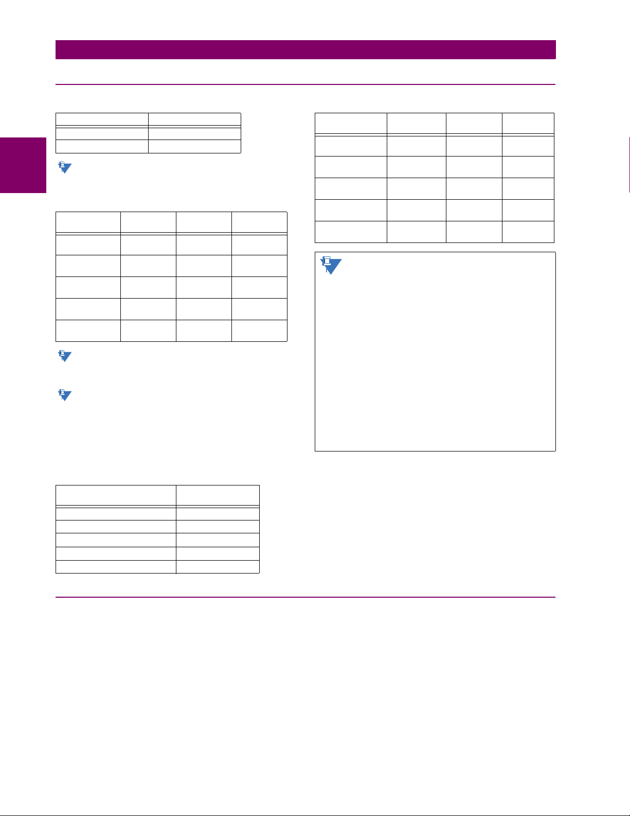
2.2 SPECIFICATIONS 2 PRODUCT DESCRIPTION
NOTE
NOTE
NOTE
NOTE
2.2.9 INTER-RELAY COMMUNICATIONS
SHIELDED TWISTED-PAIR INTERFACE OPTIONS
INTERFACE TYPE TYPICAL DISTANCE
RS422 1200 m
G.703 100 m
2
RS422 distance is based on transmitter power and
does not take into consideration the clock source
provided by the user.
LINK POWER BUDGET
EMITTER,
FIBER TYPE
820 nm LED,
Multimode
1300 nm LED,
Multimode
1300 nm ELED,
Singlemode
1300 nm Laser,
Singlemode
1550 nm Laser,
Singlemode
TRANSMIT
POWER
–20 dBm –30 dBm 10 dB
–21 dBm –30 dBm 9 dB
–23 dBm –32 dBm 9 dB
–1 dBm –30 dBm 29 dB
+5 dBm –30 dBm 35 dB
RECEIVED
SENSITIVITY
These power budgets are calculated from the manufacturer’s worst-case transmitter power and worst
case receiver sensitivity.
The power budgets for the 1300 nm ELED are calculated from the manufacturer's transmitter power and
receiver sensitivity at ambient temperature. At
extreme temperatures these values deviate based
on component tolerance. On average, the output
power decreases as the temperature is increased by
a factor 1dB / 5°C.
MAXIMUM OPTICAL INPUT POWER
EMITTER, FIBER TYPE MAX. OPTICAL
820 nm LED, Multimode –7.6 dBm
1300 nm LED, Multimode –11 dBm
1300 nm ELED, Singlemode –14 dBm
1300 nm Laser, Singlemode –14 dBm
1550 nm Laser, Singlemode –14 dBm
INPUT POWER
POWER
BUDGET
TYPICAL LINK DISTANCE
EMITTER TYPE CABLE
820 nm LED,
multimode
1300 nm LED,
multimode
1300 nm ELED,
single mode
1300 nm Laser,
single mode
1550 nm Laser,
single-mode
TYPE
62.5/125 μm ST 1.65 km
62.5/125 μm ST 3.8 km
9/125 μm ST 11.4 km
9/125 μm ST 64 km
9/125 μm ST 105 km
CONNECTOR
TYPE
TYPICAL
DISTANCE
Typical distances listed are based on the following assumptions for system loss. As actual losses
vary from one installation to another, the distance
covered by your system may vary.
CONNECTOR LOSSES (TOTAL OF BOTH ENDS)
ST connector 2 dB
FIBER LOSSES
820 nm multimode 3 dB/km
1300 nm multimode 1 dB/km
1300 nm singlemode 0.35 dB/km
1550 nm singlemode 0.25 dB/km
Splice losses: One splice every 2 km,
at 0.05 dB loss per splice.
SYSTEM MARGIN
3 dB additional loss added to calculations to compensate for
all other losses.
Compensated difference in transmitting and receiving (channel
asymmetry) channel delays using GPS satellite clock: 10 ms
2.2.10 ENVIRONMENTAL
AMBIENT TEMPERATURES
Storage temperature: –40 to 85°C
Operating temperature: –40 to 60°C; the LCD contrast can be
impaired at temperatures less than –
20°C
OTHER
Altitude: 2000 m (maximum)
Pollution degree: II
Overvoltage category: II
Ingress protection: IP20 front, IP10 back
HUMIDITY
Humidity: operating up to 95% (non-condensing) at
55°C (as per IEC60068-2-30 variant 1, 6
days).
2-16 B90 Low Impedance Bus Differential System GE Multilin
Page 45

2 PRODUCT DESCRIPTION 2.2 SPECIFICATIONS
2.2.11 TYPE TESTS
B90 TYPE TESTS
TEST REFERENCE STANDARD TEST LEVEL
Dielectric voltage withstand EN60255-5 2.2 kV
Impulse voltage withstand EN60255-5 5 kV
Damped oscillatory IEC61000-4-18 / IEC60255-22-1 2.5 kV CM, 1 kV DM
Electrostatic discharge EN61000-4-2 / IEC60255-22-2 Level 3
RF immunity EN61000-4-3 / IEC60255-22-3 Level 3
Fast transient disturbance EN61000-4-4 / IEC60255-22-4 Class A and B
Surge immunity EN61000-4-5 / IEC60255-22-5 Level 3 and 4
Conducted RF immunity EN61000-4-6 / IEC60255-22-6 Level 3
Power frequency immunity EN61000-4-7 / IEC60255-22-7 Class A and B
Voltage interruption and ripple DC IEC60255-11 12% ripple, 200 ms interrupts
Radiated and conducted emissions CISPR11 / CISPR22 / IEC60255-25 Class A
Sinusoidal vibration IEC60255-21-1 Class 1
Shock and bump IEC60255-21-2 Class 1
Seismic IEC60255-21-3 Class 1
Power magnetic immunity IEC61000-4-8 Level 5
Pulse magnetic immunity IEC61000-4-9 Level 4
Damped magnetic immunity IEC61000-4-10 Level 4
Voltage dip and interruption IEC61000-4-11 0, 40, 70, 80% dips; 250 / 300 cycle interrupts
Damped oscillatory IEC61000-4-12 2.5 kV CM, 1 kV DM
Conducted RF immunity, 0 to 150 kHz IEC61000-4-16 Level 4
Voltage ripple IEC61000-4-17 15% ripple
Ingress protection IEC60529 IP40 front, IP10 back
Cold IEC60068-2-1 –40°C for 16 hours
Hot IEC60068-2-2 85°C for 16 hours
Humidity IEC60068-2-30 6 days, variant 1
Damped oscillatory IEEE/ANSI C37.90.1 2.5 kV, 1 MHz
RF immunity IEEE/ANSI C37.90.2 20 V/m, 80 MHz to 1 GHz
Safety UL508 e83849 NKCR
Safety UL C22.2-14 e83849 NKCR7
Safety UL1053 e83849 NKCR
2
2.2.12 PRODUCTION TESTS
THERMAL
Products go through an environmental test based upon an
Accepted Quality Level (AQL) sampling process.
GE Multilin B90 Low Impedance Bus Differential System 2-17
Page 46

2.2 SPECIFICATIONS 2 PRODUCT DESCRIPTION
APPROVALS
2
COMPLIANCE APPLICABLE
CE Low voltage directive EN 60255-5
C-UL-US --- UL 508
COUNCIL DIRECTIVE
EMC directive EN 60255-26 / EN 50263
ACCORDING TO
EN 61000-6-5
UL 1053
C22.2 No. 14
2.2.14 MAINTENANCE
MOUNTING
Attach mounting brackets using 20 inch-pounds (±2 inch-pounds) of torque.
CLEANING
Normally, cleaning is not required; but for situations where dust has accumulated on the faceplate display, a dry cloth can be used.
To avoid deterioration of electrolytic capacitors, power up units that are stored in a de-energized state once per
year, for one hour continuously.
2.2.13 APPROVALS
2-18 B90 Low Impedance Bus Differential System GE Multilin
Page 47
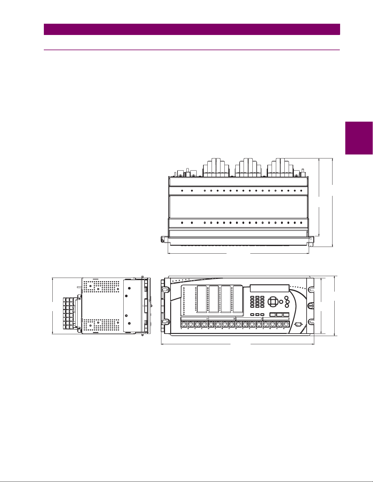
3 HARDWARE 3.1 DESCRIPTION
17.56”
[446,02 mm]
9.687”
[246,05 mm]
11.016”
[279,81 mm]
7.460”
[189,48 mm]
6.960”
[176,78 mm]
19.040”
[483,62 mm]
6.995”
[177,67 mm]
842807A1.CDR
3 HARDWARE 3.1DESCRIPTION 3.1.1 PANEL CUTOUT
The B90 Low Impedance Bus Differential System is available as a 19-inch rack horizontal mount unit with a removable
faceplate. The faceplate can be specified as either standard or enhanced at the time of ordering. The enhanced faceplate
contains additional user-programmable pushbuttons and LED indicators.
The modular design allows the relay to be easily upgraded or repaired by a qualified service person. The faceplate is
hinged to allow easy access to the removable modules, and is itself removable to allow mounting on doors with limited rear
depth.
The case dimensions are shown below, along with panel cutout details for panel mounting. When planning the location of
your panel cutout, ensure that provision is made for the faceplate to swing open without interference to or from adjacent
equipment.
The relay must be mounted such that the faceplate sits semi-flush with the panel or switchgear door, allowing the operator
access to the keypad and the RS232 communications port. The relay is secured to the panel with the use of four screws
supplied with the relay.
3
Figure 3–1: B90 HORIZONTAL DIMENSIONS (ENHANCED PANEL)
GE Multilin B90 Low Impedance Bus Differential System 3-1
Page 48

3.1 DESCRIPTION 3 HARDWARE
18.370”
[466,60 mm]
842808A1.CDR
0.280”
[7,11 mm]
Typ.x4
4.000”
[101,60 mm]
17.750”
[450,85 mm]
CUT-OUT
3
Figure 3–2: B90 HORIZONTAL MOUNTING (ENHANCED PANEL)
Figure 3–3: B90 HORIZONTAL MOUNTING AND DIMENSIONS (STANDARD PANEL)
3-2 B90 Low Impedance Bus Differential System GE Multilin
Page 49

3 HARDWARE 3.1 DESCRIPTION
842812A1.CDR
3.1.2 MODULE WITHDRAWAL AND INSERTION
Withdraw or insert a module only when control power has been removed from the unit, and be
sure to inserting only the correct module type into a slot, else personal injury, damage to the
unit or connected equipment, or undesired operation can result.
To avoid damage to the equipment, use proper electrostatic discharge protection (for example, a
static strap) when coming in contact with modules while the relay is energized.
The relay, being modular in design, allows for the withdrawal and insertion of modules. Modules must only be replaced with
like modules in their original factory configured slots.
The enhanced faceplate can be opened to the left, once the thumb screw has been removed, as shown below. This allows
for easy accessibility of the modules for withdrawal. The new wide-angle hinge assembly in the enhanced front panel opens
completely and allows easy access to all modules in the B90.
3
Figure 3–4: UR MODULE WITHDRAWAL AND INSERTION (ENHANCED FACEPLATE)
The standard faceplate can be opened to the left, once the sliding latch on the right side has been pushed up, as shown
below. This allows for easy accessibility of the modules for withdrawal.
Figure 3–5: UR MODULE WITHDRAWAL AND INSERTION (STANDARD FACEPLATE)
To properly remove a module, the ejector/inserter clips, located at the top and bottom of each module, must be pulled
simultaneously. Before performing this action, control power must be removed from the relay. Record the original location of the module to ensure that the same or replacement module is inserted into the correct slot. Modules with current
input provide automatic shorting of external CT circuits.
GE Multilin B90 Low Impedance Bus Differential System 3-3
Page 50
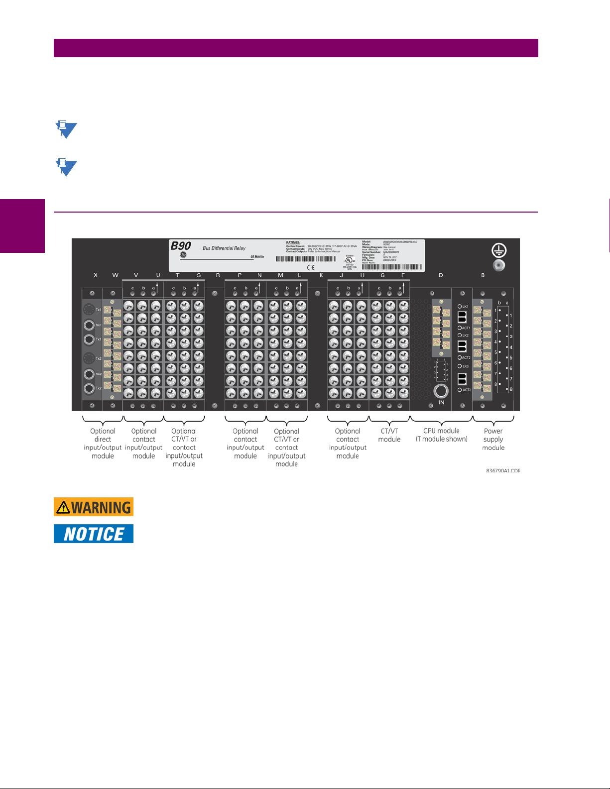
3.1 DESCRIPTION 3 HARDWARE
NOTE
To properly insert a module, ensure that the correct module type is inserted into the correct slot position. The ejector/
inserter clips located at the top and at the bottom of each module must be in the disengaged position as the module is
smoothly inserted into the slot. Once the clips have cleared the raised edge of the chassis, engage the clips simultaneously.
When the clips have locked into position, the module will be fully inserted.
CPU modules have 100Base-FX connectors. These connectors must be individually disconnected from the module
before it can be removed from the chassis.
The new CT/VT modules can only be used with new CPUs; similarly, old CT/VT modules can only be used with old
CPUs. In the event that there is a mismatch between the CPU and CT/VT module, the relay does not function and
DSP ERROR or HARDWARE MISMATCH error displays.
a
3.1.3 REAR TERMINAL LAYOUT
3
Figure 3–6: REAR TERMINAL VIEW
Do not touch any rear terminals while the relay is energized!
The small form-factor pluggable ports (SFPs) are pluggable transceivers. Do not use non-validated
transceivers or install validated transceivers in the wrong Ethernet slot, else damage can occur.
The relay follows a convention with respect to terminal number assignments which are three characters long assigned in
order by module slot position, row number, and column letter. Two-slot wide modules take their slot designation from the
first slot position (nearest to CPU module) which is indicated by an arrow marker on the terminal block. See the following
figure for an example of rear terminal assignments.
3-4 B90 Low Impedance Bus Differential System GE Multilin
Page 51
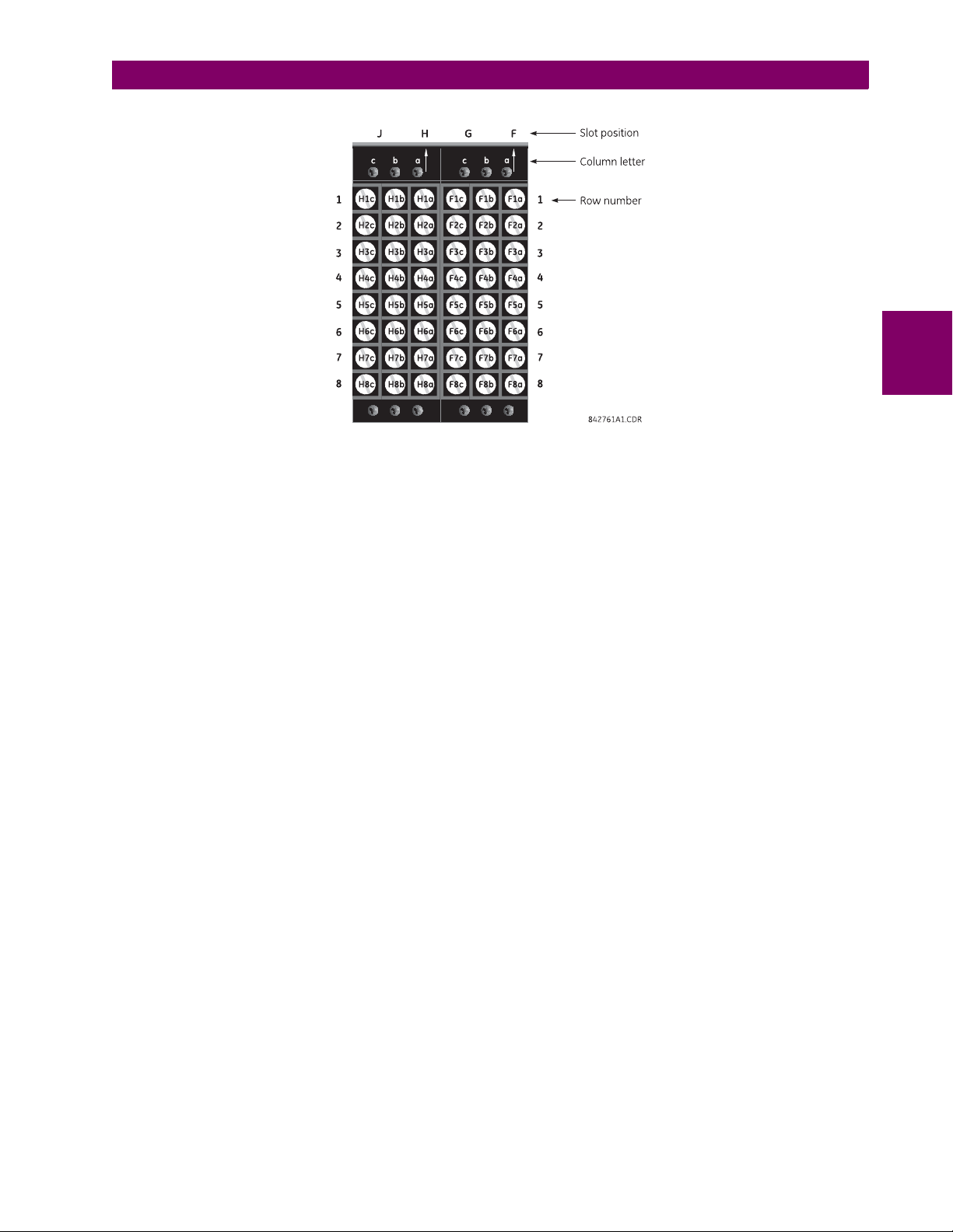
3 HARDWARE 3.1 DESCRIPTION
Figure 3–7: EXAMPLE OF MODULES IN F AND H SLOTS
3
GE Multilin B90 Low Impedance Bus Differential System 3-5
Page 52
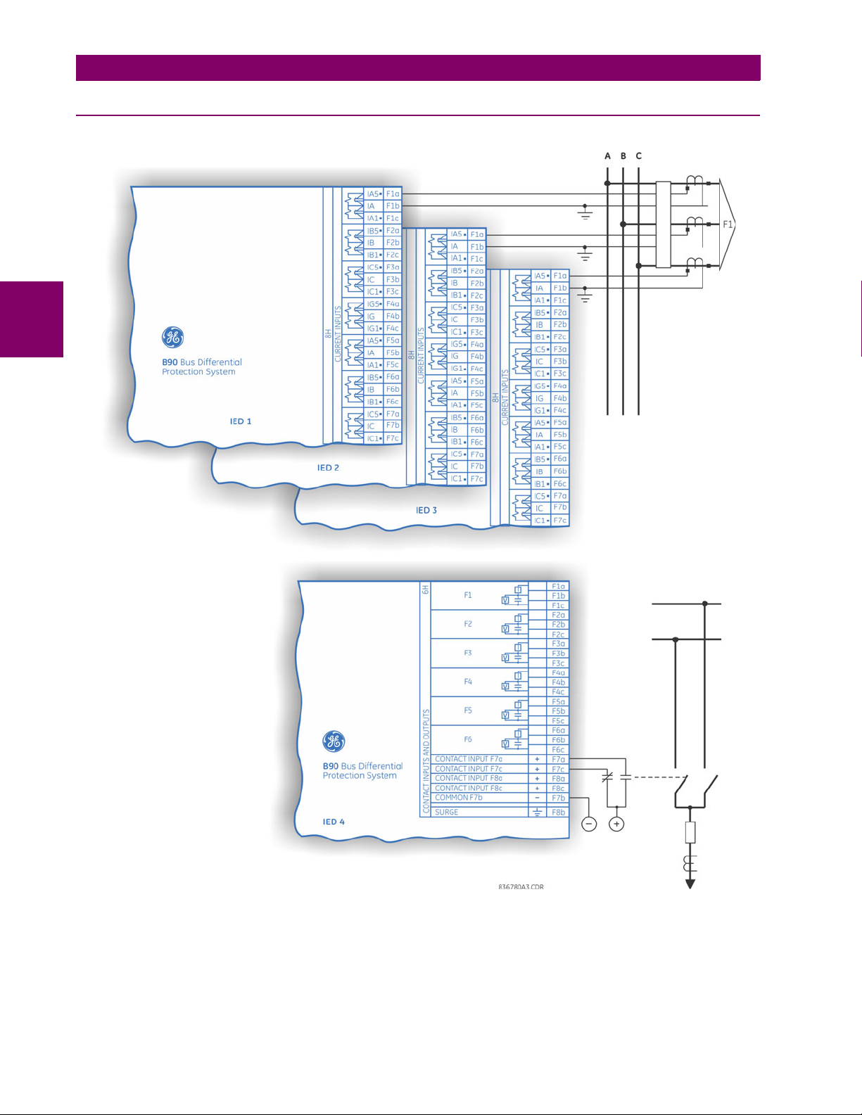
3.2 WIRING 3 HARDWARE
3.2WIRING 3.2.1 TYPICAL WIRING
3
Figure 3–8: B90 IS A MULTI-IED PROTECTION SYSTEM
3-6 B90 Low Impedance Bus Differential System GE Multilin
Page 53

3 HARDWARE 3.2 WIRING
The wiring diagrams on the next four pages are based on the following order code:
B90-H02-HCL-F8H-H6H-L8H-N6A-S8H-U6H-W7H.
The purpose of these diagrams is to provide examples of how the B90 is typically wired, not
specifically how to wire your own relay. Please refer to the sections following the wiring diagrams for examples on connecting your relay correctly based on your relay configuration and
order code.
3
GE Multilin B90 Low Impedance Bus Differential System 3-7
Page 54

3
3.2 WIRING 3 HARDWARE
Figure 3–9: TYPICAL WIRING DIAGRAM (PHASE A)
3-8 B90 Low Impedance Bus Differential System GE Multilin
Page 55
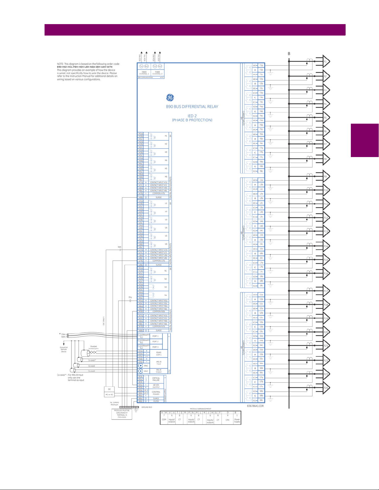
3 HARDWARE 3.2 WIRING
3
Figure 3–10: TYPICAL WIRING DIAGRAM (PHASE B)
GE Multilin B90 Low Impedance Bus Differential System 3-9
Page 56
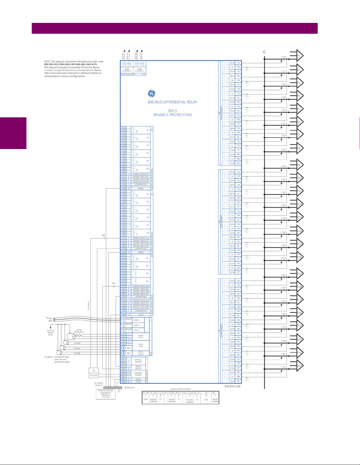
3
3.2 WIRING 3 HARDWARE
Figure 3–11: TYPICAL WIRING DIAGRAM (PHASE C)
3-10 B90 Low Impedance Bus Differential System GE Multilin
Page 57

3 HARDWARE 3.2 WIRING
3
Figure 3–12: TYPICAL WIRING DIAGRAM (BREAKER FAIL AND ISOLATOR MONITORING)
GE Multilin B90 Low Impedance Bus Differential System 3-11
Page 58

3.2 WIRING 3 HARDWARE
The dielectric strength of the UR-series module hardware is shown in the following table:
Table 3–1: DIELECTRIC STRENGTH OF UR-SERIES MODULE HARDWARE
3
MODULE
TYPE
1 Power supply High (+); Low (+); (–) Chassis 2000 V AC for 1 minute
1 Power supply 48 V DC (+) and (–) Chassis 2000 V AC for 1 minute
1 Power supply Relay terminals Chassis 2000 V AC for 1 minute
2 Reserved N/A N/A N/A
3 Reserved N/A N/A N/A
4 Reserved N/A N/A N/A
5 Analog inputs/outputs All except 8b Chassis < 50 V DC
6 Digital inputs/outputs All Chassis 2000 V AC for 1 minute
7
8 CT/VT All Chassis 2000 V AC for 1 minute
9 CPU All Chassis 2000 V AC for 1 minute
MODULE FUNCTION TERMINALS DIELECTRIC STRENGTH
FROM TO
G.703 All except 2b, 3a, 7b, 8a Chassis 2000 V AC for 1 minute
RS422 All except 6a, 7b, 8a Chassis < 50 V DC
Filter networks and transient protection clamps are used in the hardware to prevent damage caused
by high peak voltage transients, radio frequency interference (RFI), and electromagnetic interference
(EMI). These protective components can be damaged by application of the ANSI/IEEE C37.90 specified test voltage for a period longer than the specified one minute.
3.2.2 DIELECTRIC STRENGTH
(AC)
3.2.3 CONTROL POWER
Control power supplied to the relay must be connected to the matching power supply range of the
relay. If the voltage is applied to the wrong terminals, damage can occur.
The B90 relay, like almost all electronic relays, contains electrolytic capacitors. These capacitors are
well known to be subject to deterioration over time if voltage is not applied periodically. Deterioration
can be avoided by powering the relays up once a year.
The power supply module can be ordered for two possible voltage ranges, with or without a redundant power option. Each
range has a dedicated input connection for proper operation. The ranges are as shown below (see the Technical specifica-
tions section of chapter 2 for additional details):
• Low (LO) range: 24 to 48 V (DC only) nominal.
• High (HI) range: 125 to 250 V nominal.
The power supply module provides power to the relay and supplies power for dry contact input connections.
The power supply module provides 48 V DC power for dry contact input connections and a critical failure relay (see the
Typical wiring diagram earlier). The critical failure relay is a form-C device that is energized once control power is applied
and the relay has successfully booted up with no critical self-test failures. If on-going self-test diagnostic checks detect a
critical failure (see the Self-test errors section in chapter 7) or control power is lost, the relay is de-energize.
For high reliability systems, the B90 has a redundant option in which two B90 power supplies are placed in parallel on the
bus. If one of the power supplies become faulted, the second power supply assumes the full load of the relay without any
interruptions. Each power supply has a green LED on the front of the module to indicate it is functional. The critical fail relay
of the module also indicates a faulted power supply.
An LED on the front of the control power module shows the status of the power supply:
LED INDICATION POWER SUPPLY
CONTINUOUS ON OK
ON / OFF CYCLING Failure
OFF Failure
3-12 B90 Low Impedance Bus Differential System GE Multilin
Page 59
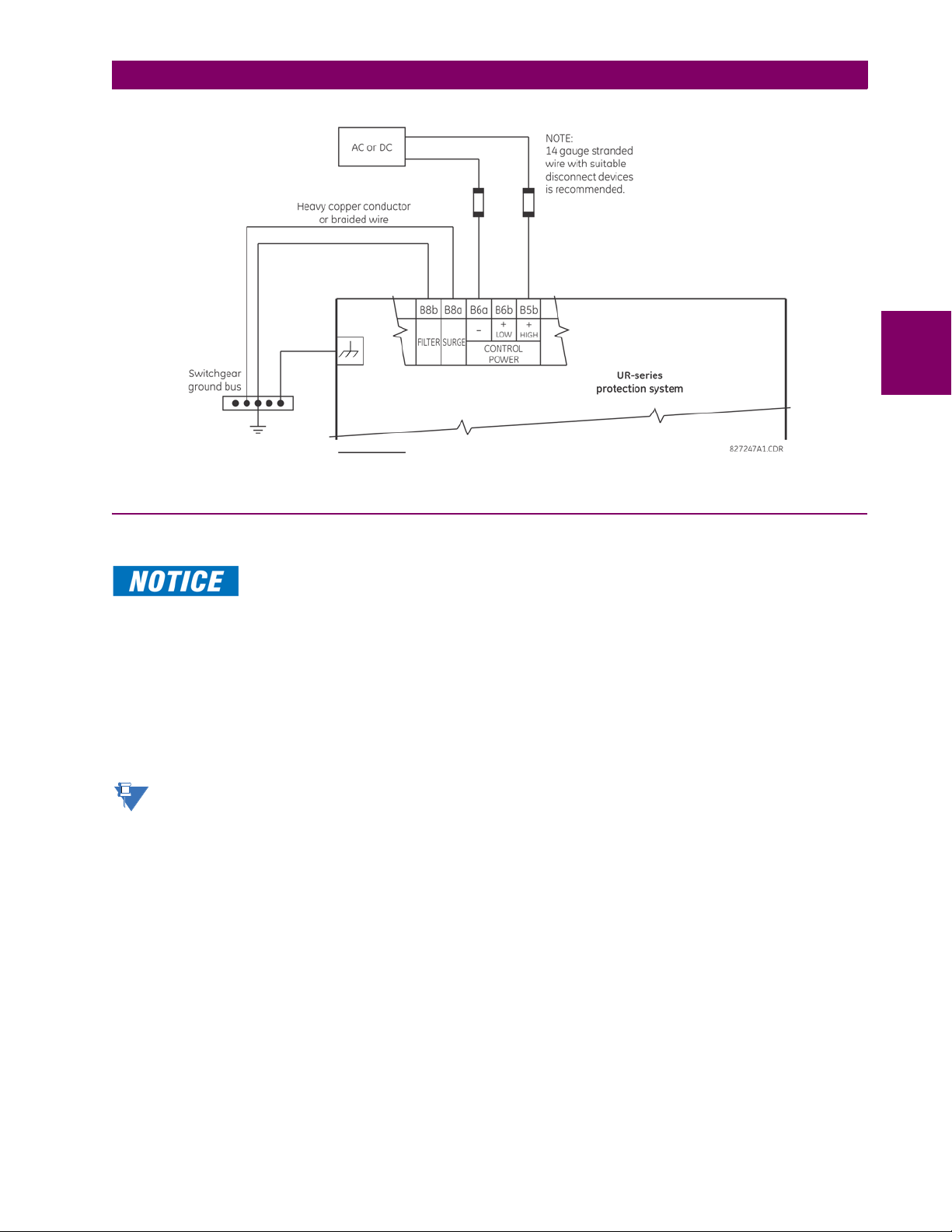
3 HARDWARE 3.2 WIRING
Figure 3–13: CONTROL POWER CONNECTION
3.2.4 CT AND VT MODULES
3
Information on the CT and VT modules for the B90 relay is shown below.
Verify that the connection made to the relay nominal current of 1 A or 5 A matches the secondary rating of the connected CTs. Unmatched CTs may result in equipment damage or inadequate protection.
Each AC current input has an isolating transformer and an automatic shorting mechanism that shorts the input when the
module is withdrawn from the chassis. There are no internal ground connections on the current inputs. Current transformers with 1 to 50000 A primaries and 1 A or 5 A secondaries may be used.
Each B90 voltage input is intended for monitoring a single-phase voltage. The may include phase voltages or neutral voltage from the open-delta VT.
All CT and VT modules are available with enhanced diagnostics. These modules can automatically detect CT/VT hardware
failure and take the relay out of service.
Substitute the tilde “~” symbol with the slot position of the module in the following figure.
GE Multilin B90 Low Impedance Bus Differential System 3-13
Page 60
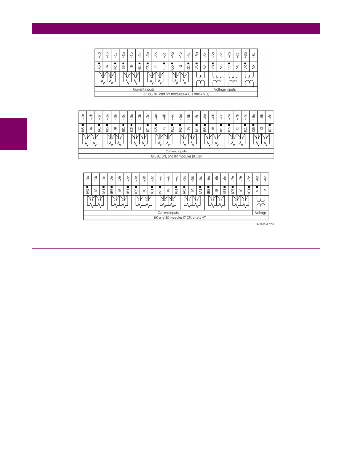
3
3.2 WIRING 3 HARDWARE
Figure 3–14: CT/VT MODULE WIRING
3.2.5 CONTACT INPUTS AND OUTPUTS
Every contact input/output module has 24 terminal connections. They are arranged as three terminals per row, with eight
rows in total. A given row of three terminals can be used for the outputs of one relay. For example, for form-C relay outputs,
the terminals connect to the normally open (NO), normally closed (NC), and common contacts of the relay. For a form-A
output, there are options of using current or voltage detection for feature supervision, depending on the module ordered.
The terminal configuration for contact inputs is different for the two applications.
The contact inputs are grouped with a common return. The B90 has two versions of grouping: four inputs per common
return and two inputs per common return. When a contact input/output module is ordered, four inputs per common is used.
The four inputs per common allows for high-density inputs in combination with outputs, with a compromise of four inputs
sharing one common. If the inputs must be isolated per row, then two inputs per common return should be selected (4D
module).
The tables and diagrams on the following pages illustrate the module types (6A, etc.) and contact arrangements that can be
ordered for the relay. Since an entire row is used for a single contact output, the name is assigned using the module slot
position and row number. However, since there are two contact inputs per row, these names are assigned by module slot
position, row number, and column position.
Some form-A / solid-state relay outputs include circuits to monitor the DC voltage across the output contact when it is open,
and the DC current through the output contact when it is closed. Each of the monitors contains a level detector whose output is set to logic “On = 1” when the current in the circuit is above the threshold setting. The voltage monitor is set to “On =
1” when the current is above about 1 to 2.5 mA, and the current monitor is set to “On = 1” when the current exceeds about
80 to 100 mA. The voltage monitor is intended to check the health of the overall trip circuit, and the current monitor can be
used to seal-in the output contact until an external contact has interrupted current flow.
Block diagrams are shown as follows for form-A and solid-state relay outputs with optional voltage monitor, optional current
monitor, and with no monitoring. The actual values shown for contact output 1 are the same for all contact outputs.
3-14 B90 Low Impedance Bus Differential System GE Multilin
Page 61

3 HARDWARE 3.2 WIRING
/RDG
,
aD
aE
aF
,I,GF P$
RWKHUZLVH
&RQW2S
&RQW2S
´92Qµ
´92IIµ
9
$&'5
D9ROWDJHZLWKRSWLRQDO
FXUUHQWPRQLWRULQJ
9ROWDJHPRQLWRULQJRQO\
/RDG
,
9
%RWKYROWDJHDQGFXUUHQWPRQLWRULQJ
,I,GF P$ &RQW2S
&RQW2S
´,2Qµ
RWKHUZLVH ´,2IIµ
,I,GF P$
RWKHUZLVH
&RQW2S
&RQW2S
´92Qµ
´92IIµ
/RDG
,
9
E&XUUHQWZLWKRSWLRQDO
YROWDJHPRQLWRULQJ
&XUUHQWPRQLWRULQJRQO\ %RWKYROWDJHDQGFXUUHQWPRQLWRULQJ
H[WHUQDOMXPSHUDELVUHTXLUHG
,I,GF P$ &RQW2S
&RQW2S
´,2Qµ
RWKHUZLVH ´,2IIµ
/RDG
9
,I,GF P$ &RQW2S
&RQW2S
´,2Qµ
RWKHUZLVH ´,2IIµ
,I,GF P$
RWKHUZLVH
&RQW2S
&RQW2S
´92Qµ
´92IIµ
/RDG
F1RPRQLWRULQJ
aD
aE
aF
aD
aE
aF
aD
aE
aF
aD
aE
aF
,
NOTE
NOTE
3
Figure 3–15: FORM-A AND SOLID-STATE CONTACT OUTPUTS WITH VOLTAGE AND CURRENT MONITORING
The operation of voltage and current monitors is reflected with the corresponding FlexLogic operands (CONT OP # VON,
CONT OP # VOFF, and CONT OP # ION) which can be used in protection, control, and alarm logic. The typical application of
the voltage monitor is breaker trip circuit integrity monitoring; a typical application of the current monitor is seal-in of the
control command.
Refer to the Digital elements section of chapter 5 for an example of how form-A and solid-state relay contacts can be
applied for breaker trip circuit integrity monitoring.
Consider relay contacts unsafe to touch when the unit is energized. If the relay contacts need
to be used for low voltage accessible applications, ensure proper insulation levels.
USE OF FORM-A AND SOLID-STATE RELAY OUTPUTS IN HIGH IMPEDANCE CIRCUITS
For form-A and solid-state relay output contacts internally equipped with a voltage measuring circuit across the contact, the circuit has an impedance that can cause a problem when used in conjunction with external high input
impedance monitoring equipment such as modern relay test set trigger circuits. These monitoring circuits may continue to read the form-A contact as being closed after it has closed and subsequently opened, when measured as
an impedance.
The solution is to use the voltage measuring trigger input of the relay test set, and connect the form-A contact
through a voltage-dropping resistor to a DC voltage source. If the 48 V DC output of the power supply is used as a
source, a 500 , 10 W resistor is appropriate. In this configuration, the voltage across either the form-A contact or
the resistor can be used to monitor the state of the output.
Wherever a tilde “~” symbol appears, substitute with the slot position of the module; wherever a number sign “#”
appears, substitute the contact number
When current monitoring is used to seal-in the form-A and solid-state relay contact outputs, the FlexLogic operand driving the contact output should be given a reset delay of 10 ms to prevent damage
of the output contact (in situations when the element initiating the contact output is bouncing, at values in the region of the pickup value).
GE Multilin B90 Low Impedance Bus Differential System 3-15
Page 62

3.2 WIRING 3 HARDWARE
Table 3–2: CONTACT INPUT AND OUTPUT MODULE ASSIGNMENTS
~6A MODULE ~6B MODULE ~6C MODULE ~6D MODULE
TERMINAL
ASSIGNMENT
~1 Form-A ~1 Form-A ~1 Form-C ~1a, ~1c 2 Inputs
~2 Form-A ~2 Form-A ~2 Form-C ~2a, ~2c 2 Inputs
~3 Form-C ~3 Form-C ~3 Form-C ~3a, ~3c 2 Inputs
~4 Form-C ~4 Form-C ~4 Form-C ~4a, ~4c 2 Inputs
~5a, ~5c 2 Inputs ~5 Form-C ~5 Form-C ~5a, ~5c 2 Inputs
~6a, ~6c 2 Inputs ~6 Form-C ~6 Form-C ~6a, ~6c 2 Inputs
~7a, ~7c 2 Inputs ~7a, ~7c 2 Inputs ~7 Form-C ~7a, ~7c 2 Inputs
~8a, ~8c 2 Inputs ~8a, ~8c 2 Inputs ~8 Form-C ~8a, ~8c 2 Inputs
OUTPUT OR
INPUT
TER MINA L
ASSIGNMENT
OUTPUT OR
INPUT
3
~6E MODULE ~6F MODULE ~6G MODULE ~6H MODULE
TERMINAL
ASSIGNMENT
~1Form-C ~1 Fast Form-C ~1Form-A ~1Form-A
~2Form-C ~2 Fast Form-C ~2Form-A ~2Form-A
~3Form-C ~3 Fast Form-C ~3Form-A ~3Form-A
~4Form-C ~4 Fast Form-C ~4Form-A ~4Form-A
~5a, ~5c 2 Inputs ~5 Fast Form-C ~5a, ~5c 2 Inputs ~5 Form-A
~6a, ~6c 2 Inputs ~6 Fast Form-C ~6a, ~6c 2 Inputs ~6 Form-A
~7a, ~7c 2 Inputs ~7 Fast Form-C ~7a, ~7c 2 Inputs ~7a, ~7c 2 Inputs
~8a, ~8c 2 Inputs ~8 Fast Form-C ~8a, ~8c 2 Inputs ~8a, ~8c 2 Inputs
OUTPUT OR
INPUT
TER MINA L
ASSIGNMENT
OUTPUT TERMINAL
TERMINAL
ASSIGNMENT
ASSIGNMENT
OUTPUT TERMINAL
OUTPUT OR
INPUT
ASSIGNMENT
TER MINA L
ASSIGNMENT
OUTPUT
OUTPUT OR
INPUT
~6K MODULE ~6L MODULE ~6M MODULE ~6N MODULE
TERMINAL
ASSIGNMENT
~1 Form-C ~1Form-A ~1Form-A ~1Form-A
~2 Form-C ~2Form-A ~2Form-A ~2Form-A
~3 Form-C ~3Form-C ~3Form-C ~3Form-A
~4 Form-C ~4Form-C ~4Form-C ~4Form-A
~5 Fast Form-C ~5a, ~5c 2 Inputs ~5Form-C ~5a, ~5c 2 Inputs
~6 Fast Form-C ~6a, ~6c 2 Inputs ~6Form-C ~6a, ~6c 2 Inputs
~7 Fast Form-C ~7a, ~7c 2 Inputs ~7a, ~7c 2 Inputs ~7a, ~7c 2 Inputs
~8 Fast Form-C ~8a, ~8c 2 Inputs ~8a, ~8c 2 Inputs ~8a, ~8c 2 Inputs
~6P MODULE ~6R MODULE ~6S MODULE ~6T MODULE
TERMINAL
ASSIGNMENT
~1 Form-A ~1Form-A ~1Form-A ~1Form-A
~2 Form-A ~2Form-A ~2Form-A ~2Form-A
~3 Form-A ~3Form-C ~3Form-C ~3Form-A
~4 Form-A ~4Form-C ~4Form-C ~4Form-A
~5 Form-A ~5a, ~5c 2 Inputs ~5Form-C ~5a, ~5c 2 Inputs
~6 Form-A ~6a, ~6c 2 Inputs ~6Form-C ~6a, ~6c 2 Inputs
~7a, ~7c 2 Inputs ~7a, ~7c 2 Inputs ~7a, ~7c 2 Inputs ~7a, ~7c 2 Inputs
~8a, ~8c 2 Inputs ~8a, ~8c 2 Inputs ~8a, ~8c 2 Inputs ~8a, ~8c 2 Inputs
OUTPUT TERMINAL
OUTPUT OR
INPUT
ASSIGNMENT
TER MINA L
ASSIGNMENT
OUTPUT OR
INPUT
OUTPUT OR
INPUT
TERMINAL
ASSIGNMENT
TERMINAL
ASSIGNMENT
OUTPUT OR
INPUT
OUTPUT OR
INPUT
TER MINA L
ASSIGNMENT
TER MINA L
ASSIGNMENT
OUTPUT OR
INPUT
OUTPUT OR
INPUT
3-16 B90 Low Impedance Bus Differential System GE Multilin
Page 63

3 HARDWARE 3.2 WIRING
~6U MODULE ~6V MODULE ~67 MODULE ~4A MODULE
TERMINAL
ASSIGNMENT
~1 Form-A ~1 Form-A ~1Form-A ~1Not Used
~2 Form-A ~2 Form-A ~2Form-A ~2 Solid-State
~3 Form-A ~3 Form-C ~3Form-A ~3Not Used
~4 Form-A ~4 2 Outputs ~4Form-A ~4 Solid-State
~5 Form-A ~5a, ~5c 2 Inputs ~5Form-A ~5Not Used
~6 Form-A ~6a, ~6c 2 Inputs ~6Form-A ~6 Solid-State
~7a, ~7c 2 Inputs ~7a, ~7c 2 Inputs ~7Form-A ~7Not Used
~8a, ~8c 2 Inputs ~8a, ~8c 2 Inputs ~8Form-A ~8 Solid-State
TERMINAL
ASSIGNMENT
~1Not Used ~1 Not Used ~1a, ~1c 2 Inputs ~1 2 Outputs
~2 Solid-State ~2 Solid-State ~2a, ~2c 2 Inputs ~2 2 Outputs
~3Not Used ~3 Not Used ~3a, ~3c 2 Inputs ~3 2 Outputs
~4 Solid-State ~4 Solid-State ~4a, ~4c 2 Inputs ~4 2 Outputs
~5Not Used ~5 Not Used ~5a, ~5c 2 Inputs ~5 2 Outputs
~6 Solid-State ~6 Solid-State ~6a, ~6c 2 Inputs ~6 2 Outputs
~7Not Used ~7 Not Used ~7a, ~7c 2 Inputs ~72 Outputs
~8 Solid-State ~8 Solid-State ~8a, ~8c 2 Inputs ~8Not Used
OUTPUT OR
INPUT
~4B MODULE ~4C MODULE ~4D MODULE ~4L MODULE
OUTPUT TERMINAL
TER MINA L
ASSIGNMENT
ASSIGNMENT
OUTPUT OR
INPUT
OUTPUT TERMINAL
TERMINAL
ASSIGNMENT
ASSIGNMENT
OUTPUT TERMINAL
OUTPUT TERMINAL
ASSIGNMENT
ASSIGNMENT
OUTPUT
OUTPUT
3
GE Multilin B90 Low Impedance Bus Differential System 3-17
Page 64

3
3.2 WIRING 3 HARDWARE
Figure 3–16: CONTACT INPUT AND OUTPUT MODULE WIRING (1 of 2)
3-18 B90 Low Impedance Bus Differential System GE Multilin
Page 65

3 HARDWARE 3.2 WIRING
DIGITAL I/O
6K
1b
2b
3b
4b
5b
7b
6b
8b
1a
2a
3a
4a
5a
7a
6a
8a
1c
2c
3c
4c
5c
7c
6c
8c
1
5
7
2
6
8
3
4
~
~
~
~
~
~
~
~
~
~
~
~
~
~
~
~
~
~
~
~
~
~
~
~
~
~
~
~
~
~
~
~
I
V
I
V
I
V
I
V
I
V
I
V
DIGITAL I/O
6P
1b
2b
3b
4b
5b
6b
1a
2a
3a
4a
5a
6a
1c
2c
3c
4c
5c
6c
1
5
2
6
3
4
8a
7b
7a
~
~
~
~
~
~
~
~
~
~
~
~
~
~
~
~
~
~
~
~
~
~
~
~
~
~
~
~
~
~
~
~
~
~
~
CONTACT IN 7a
CONTACT IN 7c
CONTACT IN 8a
CONTACT IN 8c
COMMON 7b
SURGE
8c
7c
8b
DIGITAL I/O
6U
1b
2b
3b
4b
5b
6b
1a
2a
3a
4a
5a
6a
1c
2c
3c
4c
5c
6c
1
5
2
6
3
4
8a
7b
7a
~
~
~
~
~
~
~
~
~
~
~
~
~
~
~
~
~
~
~
~
~
~
~
~
~
~
~
~
~
~
~
~
~
~
~
CONTACT IN 7a
CONTACT IN 7c
CONTACT IN 8a
CONTACT IN 8c
COMMON 7b
SURGE
8c
7c
8b
~
~
~
~
~
~
~
~
~
~
~
~
~
~
~
~
~
~
~
~
~
~
~
~
~
~
~
~
~
~
~
~
~
~
~
I
V
I
V
DIGITAL I/O
6M
1b
2b
3b
4b
5b
6b
1a
2a
3a
4a
5a
6a
1c
2c
3c
4c
5c
6c
1
5
2
6
3
4
8a
7b
7a
CONTACT IN 7a
CONTACT IN 7c
CONTACT IN 8a
CONTACT IN 8c
COMMON 7b
SURGE
8c
7c
8b
~
~
~
~
~
~
~
~
~
~
~
~
~
~
~
~
~
~
~
~
~
~
~
~
~
~
~
~
~
~
~
~
~
~
~
DIGITAL I/O
6S
1b
2b
3b
4b
5b
6b
1a
2a
3a
4a
5a
6a
1c
2c
3c
4c
5c
6c
1
5
2
6
3
4
8a
7b
7a
CONTACT IN 7a
CONTACT IN 7c
CONTACT IN 8a
CONTACT IN 8c
COMMON 7b
SURGE
8c
7c
8b
~
~
~
~
~
~
~
~
~
~
~
~
~
~
~
~
~
~
~
~
~
~
~
~
~
~
~
~
~
~
~
~
~
~
~
~
~
I
V
I
V
I
V
I
V
DIGITAL I/O
6N
1b
2b
3b
4b
6c
1a
2a
3a
4a
5a
6a
1c
2c
3c
4c
5c
5b
1
2
3
4
8a
7b
7a
CONTACT IN 7a
CONTACT IN 5a
CONTACT IN 7c
CONTACT IN 5c
CONTACT IN 8a
CONTACT IN 6a
CONTACT IN 8c
CONTACT IN 6c
COMMON 7b
COMMON 5b
SURGE
8c
7c
8b
~
~
~
~
~
~
~
~
~
~
~
~
~
~
~
~
~
~
~
~
~
~
~
~
~
~
~
~
~
~
~
~
~
~
~
~
~
DIGITAL I/O
6T
1b
2b
3b
4b
6c
1a
2a
3a
4a
5a
6a
1c
2c
3c
4c
5c
5b
1
2
3
4
8a
7b
7a
CONTACT IN 7a
CONTACT IN 5a
CONTACT IN 7c
CONTACT IN 5c
CONTACT IN 8a
CONTACT IN 6a
CONTACT IN 8c
CONTACT IN 6c
COMMON 7b
COMMON 5b
SURGE
8c
7c
8b
~
~
~
~
~
~
~
~
~
~
~
~
~
~
~
~
~
~
~
~
~
~
~
~
~
~
~
~
~
~
~
~
~
~
~
~
~
I
V
I
V
DIGITAL I/O
6L
1b
2b
3b
4b
6c
1a
2a
3a
4a
5a
6a
1c
2c
3c
4c
5c
5b
1
2
3
4
8a
7b
7a
CONTACT IN 7a
CONTACT IN 5a
CONTACT IN 7c
CONTACT IN 5c
CONTACT IN 8a
CONTACT IN 6a
CONTACT IN 8c
CONTACT IN 6c
COMMON 7b
COMMON 5b
SURGE
8c
7c
8b
~
~
~
~
~
~
~
~
~
~
~
~
~
~
~
~
~
~
~
~
~
~
~
~
~
~
~
~
~
~
~
~
~
~
~
~
~
DIGITAL I/O
6R
1b
2b
3b
4b
6c
1a
2a
3a
4a
5a
6a
1c
2c
3c
4c
5c
5b
1
2
3
4
8a
7b
7a
CONTACT IN 7a
CONTACT IN 5a
CONTACT IN 7c
CONTACT IN 5c
CONTACT IN 8a
CONTACT IN 6a
CONTACT IN 8c
CONTACT IN 6c
COMMON 7b
COMMON 5b
SURGE
8c
7c
8b
842763A2.CDR
3
Figure 3–17: CONTACT INPUT AND OUTPUT MODULE WIRING (2 of 2)
For proper functionality, observe correct polarity for all contact input and solid state output connections.
GE Multilin B90 Low Impedance Bus Differential System 3-19
Page 66

3.2 WIRING 3 HARDWARE
NOTE
CONTACT INPUTS
A dry contact has one side connected to terminal B3b. This is the positive 48 V DC voltage rail supplied by the power supply module. The other side of the dry contact is connected to the required contact input terminal. Each contact input group
has its own common (negative) terminal which must be connected to the DC negative terminal (B3a) of the power supply
module. When a dry contact closes, a current of 1 to 3 mA flows through the associated circuit.
A wet contact has one side connected to the positive terminal of an external DC power supply. The other side of this contact
is connected to the required contact input terminal. If a wet contact is used, then the negative side of the external source
must be connected to the relay common (negative) terminal of each contact group. The maximum external source voltage
for this arrangement is 300 V DC.
The voltage threshold at which each group of four contact inputs detects a closed contact input is programmable as
17 V DC for 24 V sources, 33 V DC for 48 V sources, 84 V DC for 110 to 125 V sources, and 166 V DC for 250 V sources.
3
Figure 3–18: DRY AND WET CONTACT INPUT CONNECTIONS
Wherever a tilde “~” symbol appears, substitute with the slot position of the module.
Contact outputs can be ordered as form-A or form-C. The form-A contacts can be connected for external circuit supervision. These contacts are provided with voltage and current monitoring circuits used to detect the loss of DC voltage in the
circuit, and the presence of DC current flowing through the contacts when the form-A contact closes. If enabled, the current
monitoring can be used as a seal-in signal to ensure that the form-A contact does not attempt to break the energized inductive coil circuit and weld the output contacts.
There is no provision in the relay to detect a DC ground fault on 48 V DC control power external output. We recommend using an external DC supply.
3-20 B90 Low Impedance Bus Differential System GE Multilin
Page 67
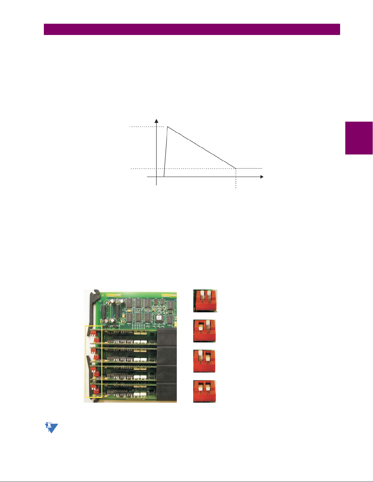
3 HARDWARE 3.2 WIRING
842749A1.CDR
50 to 70 mA
3 mA
25 to 50 ms
current
time
CONTACT INPUT 1 AUTO-BURNISH = OFF
= OFFCONTACT INPUT 2 AUTO-BURNISH
CONTACT INPUT 1 AUTO-BURNISH
CONTACT INPUT 2 AUTO-BURNISH
= ON
= OFF
CONTACT INPUT 1 AUTO-BURNISH
CONTACT INPUT 2 AUTO-BURNISH
= OFF
= ON
CONTACT INPUT 1 AUTO-BURNISH
CONTACT INPUT 2 AUTO-BURNISH
= ON
= ON
842751A1.CDR
USE OF CONTACT INPUTS WITH AUTO-BURNISHING
The contact inputs sense a change of the state of the external device contact based on the measured current. When external devices are located in a harsh industrial environment (either outdoor or indoor), their contacts can be exposed to various types of contamination. Normally, there is a thin film of insulating sulfidation, oxidation, or contaminates on the surface
of the contacts, sometimes making it difficult or impossible to detect a change of the state. This film must be removed to
establish circuit continuity – an impulse of higher than normal current can accomplish this.
The contact inputs with auto-burnish create a high current impulse when the threshold is reached to burn off this oxidation
layer as a maintenance to the contacts. Afterwards the contact input current is reduced to a steady-state current. The
impulse has a 5 second delay after a contact input changes state.
Figure 3–19: CURRENT THROUGH CONTACT INPUTS WITH AUTO-BURNISHING
Regular contact inputs limit current to less than 3 mA to reduce station battery burden. In contrast, contact inputs with autoburnishing allow currents up to 50 to 70 mA at the first instance when the change of state was sensed. Then, within 25 to
50 ms, this current is slowly reduced to 3 mA as indicated above. The 50 to 70 mA peak current burns any film on the contacts, allowing for proper sensing of state changes. If the external device contact is bouncing, the auto-burnishing starts
when external device contact bouncing is over.
Another important difference between the auto-burnishing input module and the regular input modules is that only two contact inputs have common ground, as opposed to four contact inputs sharing one common ground (refer to the Contact Input
and Output Module Wiring diagrams). This is beneficial when connecting contact inputs to separate voltage sources. Consequently, the threshold voltage setting is also defined per group of two contact inputs.
The auto-burnish feature can be disabled or enabled using the DIP switches found on each daughter card. There is a DIP
switch for each contact, for a total of 16 inputs.
3
Figure 3–20: AUTO-BURNISH DIP SWITCHES
The auto-burnish circuitry has an internal fuse for safety purposes. During regular maintenance, check the autoburnish functionality using an oscilloscope.
GE Multilin B90 Low Impedance Bus Differential System 3-21
Page 68
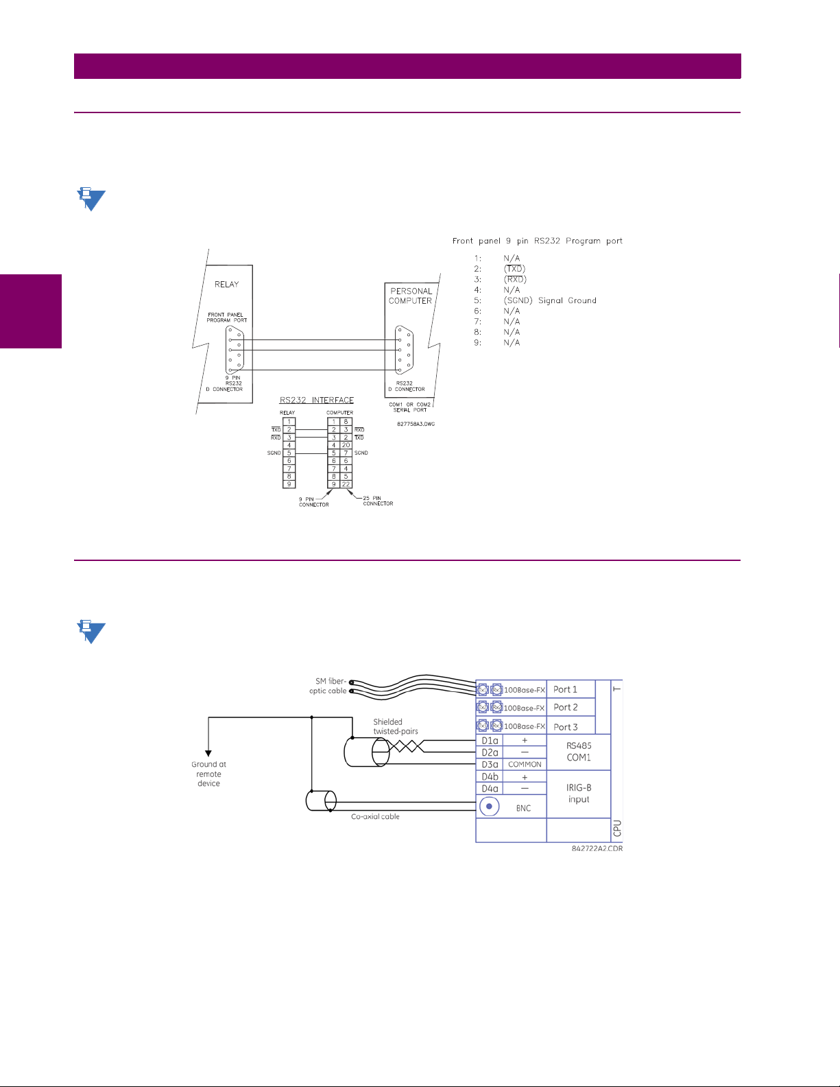
3.2 WIRING 3 HARDWARE
NOTE
NOTE
3.2.6 RS232 FACEPLATE PORT
A 9-pin RS232C serial port is located on the B90 faceplate for programming with a computer. All that is required to use this
interface is a computer running the EnerVista UR Setup software provided with the relay. Cabling for the RS232 port is
shown in the following figure for both 9-pin and 25-pin connectors.
The baud rate for this port is fixed at 19200 bps.
3
Figure 3–21: RS232 FACEPLATE PORT CONNECTION
3.2.7 CPU COMMUNICATION PORTS
a) OPTIONS
In addition to the faceplate RS232 port, the B90 provides a rear RS485 communication port.
The CPU modules do not require a surge ground connection.
Figure 3–22: CPU MODULE COMMUNICATIONS WIRING
b) RS485 PORTS
RS485 data transmission and reception are accomplished over a single twisted pair with transmit and receive data alternating over the same two wires. Through the use of the port, continuous monitoring and control from a remote computer,
SCADA system, or PLC is possible.
3-22 B90 Low Impedance Bus Differential System GE Multilin
Page 69
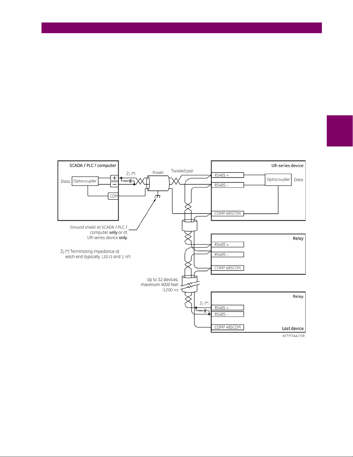
3 HARDWARE 3.2 WIRING
To minimize errors from noise, the use of shielded twisted pair wire is recommended. Correct polarity must also be
observed. For instance, the relays must be connected with all RS485 “+” terminals connected together, and all RS485 “–”
terminals connected together. Though data is transmitted over a two-wire twisted pair, all RS485 devices require a shared
reference, or common voltage. This common voltage is implied to be a power supply common. Some systems allow the
shield (drain wire) to be used as common wire and to connect directly to the B90 COM terminal (#3); others function correctly only if the common wire is connected to the B90 COM terminal, but insulated from the shield.
To avoid loop currents, ground the shield at only one point. If other system considerations require the shield to be grounded
at more than one point, install resistors (typically 100 ohms) between the shield and ground at each grounding point. Each
relay needs to be daisy-chained to the next one in the link. A maximum of 32 relays can be connected in this manner without exceeding driver capability. For larger systems, additional serial channels must be added. It is also possible to use commercially available repeaters to have more than 32 relays on a single channel. Avoid star or stub connections entirely.
Lightning strikes and ground surge currents can cause large momentary voltage differences between remote ends of the
communication link. For this reason, surge protection devices are internally provided at both communication ports. An isolated power supply with an optocoupled data interface also acts to reduce noise coupling. To ensure maximum reliability, all
equipment should have similar transient protection devices installed.
Terminate both ends of the RS485 circuit with an impedance as shown below.
3
Figure 3–23: RS485 SERIAL CONNECTION
GE Multilin B90 Low Impedance Bus Differential System 3-23
Page 70

3.2 WIRING 3 HARDWARE
NOTE
c) 10BASE-FL AND 100BASE-FX FIBER OPTIC PORTS
Ensure that the dust covers are installed when the fiber is not in use. Dirty or scratched connectors can lead to high
losses on a fiber link.
Observing any fiber transmitter output can injure the eye.
The fiber optic communication ports allow for fast and efficient communications between relays at 100 Mbps. Optical fiber
can be connected to the relay supporting a wavelength of 1310 nm in multi-mode.
The fiber optic port is designed such that the response times do not vary for any core that is 100 µm or less in diameter,
62.5 µm for 100 Mbps. For optical power budgeting, splices are required every 1 km for the transmitter/receiver pair. When
splicing optical fibers, the diameter and numerical aperture of each fiber must be the same.
3
3-24 B90 Low Impedance Bus Differential System GE Multilin
Page 71
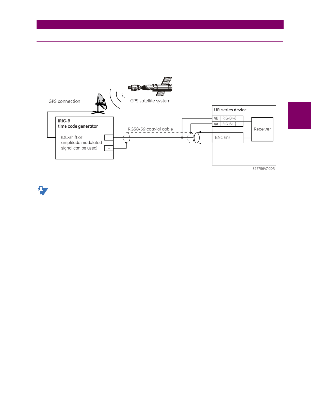
3 HARDWARE 3.2 WIRING
NOTE
3.2.8 IRIG-B
IRIG-B is a standard time code format that allows stamping of events to be synchronized among connected devices within
1 millisecond. The IRIG time code formats are serial, width-modulated codes that can be either DC level shifted or amplitude modulated (AM). Third party equipment is available for generating the IRIG-B signal; this equipment can use a GPS
satellite system to obtain the time reference so that devices at different geographic locations can be synchronized.
3
Figure 3–24: IRIG-B CONNECTION
Using an amplitude modulated receiver causes errors up to 1 ms in event time-stamping.
GE Multilin B90 Low Impedance Bus Differential System 3-25
Page 72
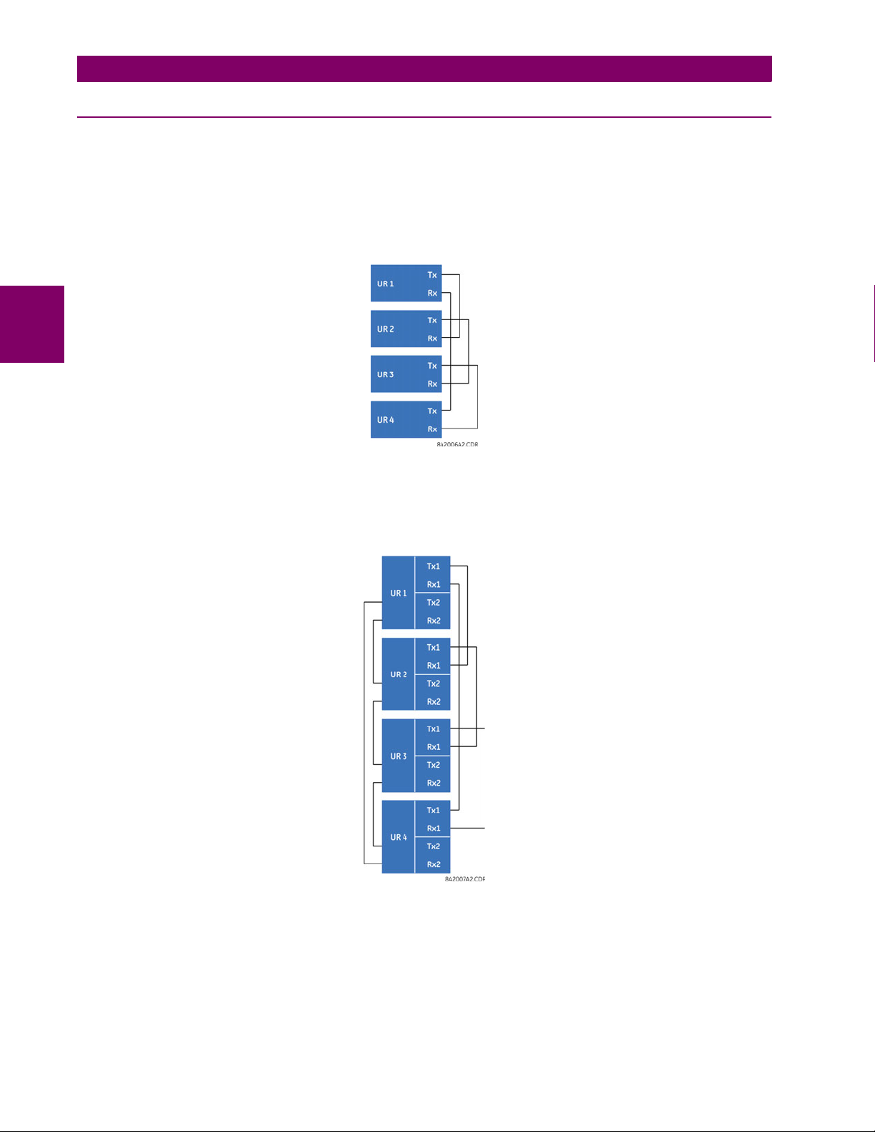
3.3 DIRECT INPUT/OUTPUT COMMUNICATIONS 3 HARDWARE
3.3DIRECT INPUT/OUTPUT COMMUNICATIONS 3.3.1 DESCRIPTION
The B90 direct inputs and outputs feature makes use of the type 7 series of communications modules, which allow direct
messaging between devices.
The communications channels are normally connected in a ring configuration as shown in the following figure. The transmitter of one module is connected to the receiver of the next module. The transmitter of this second module is then connected to the receiver of the next module in the ring. This is continued to form a communications ring. The figure illustrates
a ring of four UR-series relays with the following connections: UR1-Tx to UR2-Rx, UR2-Tx to UR3-Rx, UR3-Tx to UR4-Rx,
and UR4-Tx to UR1-Rx. A maximum of sixteen (16) UR-series relays can be connected in a single ring
3
Figure 3–25: DIRECT INPUT AND OUTPUT SINGLE CHANNEL CONNECTION
The interconnection for dual-channel Type 7 communications modules is shown as follows. Two channel modules allow for
a redundant ring configuration. That is, two rings can be created to provide an additional independent data path. The
required connections are: UR1-Tx1 to UR2-Rx1, UR2-Tx1 to UR3-Rx1, UR3-Tx1 to UR4-Rx1, and UR4-Tx1 to UR1-Rx1
for the first ring; and UR1-Tx2 to UR4-Rx2, UR4-Tx2 to UR3-Rx2, UR3-Tx2 to UR2-Rx2, and UR2-Tx2 to UR1-Rx2 for the
second ring.
Figure 3–26: DIRECT INPUT AND OUTPUT DUAL CHANNEL CONNECTION
The following diagram shows the connection for three UR-series relays using two independent communication channels.
UR1 and UR3 have single type 7 communication modules; UR2 has a dual-channel module. The two communication channels can be of different types, depending on the Type 7 modules used. To allow the direct input and output data to cross-
over from channel 1 to channel 2 on UR2, the
forces UR2 to forward messages received on Rx1 out Tx2, and messages received on Rx2 out Tx1.
3-26 B90 Low Impedance Bus Differential System GE Multilin
DIRECT I/O CHANNEL CROSSOVER setting should be “Enabled” on UR2. This
Page 73

3 HARDWARE 3.3 DIRECT INPUT/OUTPUT COMMUNICATIONS
NOTE
Figure 3–27: DIRECT INPUT AND OUTPUT SINGLE/DUAL CHANNEL COMBINATION CONNECTION
The interconnection requirements are described in further detail in this section for each specific variation of type 7 communications module. These modules are listed in the following table. All fiber modules use ST type connectors.
Not all the direct input and output communications modules may be applicable to the B90 relay. Only the modules
specified in the order codes are available as direct input and output communications modules.
Table 3–3: CHANNEL COMMUNICATION OPTIONS (Sheet 1 of 2)
MODULE SPECIFICATION
2A C37.94SM, 1300 nm, single-mode, ELED, 1 channel single-mode
2B C37.94SM, 1300 nm, single-mode, ELED, 2 channel single-mode
2E Bi-phase, 1 channel
2F Bi-phase, 2 channel
2G IEEE C37.94, 820 nm, 128 kbps, multi-mode, LED, 1 channel
2H IEEE C37.94, 820 nm, 128 kbps, multi-mode, LED, 2 channels
72 1550 nm, single-mode, laser, 1 channel
73 1550 nm, single-mode, laser, 2 channels
74 Channel 1 - RS422; channel 2 - 1550 nm, single-mode, laser
75 Channel 1 - G.703; channel 2 - 1550 nm, single-mode, laser
76 IEEE C37.94, 820 nm, 64 kbps, multi-mode, LED, 1 channel
77 IEEE C37.94, 820 nm, 64 kbps, multi-mode, LED, 2 channels
7A 820 nm, multi-mode, LED, 1 channel
7B 1300 nm, multi-mode, LED, 1 channel
7C 1300 nm, single-mode, ELED, 1 channel
7D 1300 nm, single-mode, laser, 1 channel
7E Channel 1: G.703, Channel 2: 820 nm, multi-mode
7F Channel 1: G.703, Channel 2: 1300 nm, multi-mode
7G Channel 1: G.703, Channel 2: 1300 nm, single-mode ELED
7H 820 nm, multi-mode, LED, 2 channels
7I 1300 nm, multi-mode, LED, 2 channels
7J 1300 nm, single-mode, ELED, 2 channels
7K 1300 nm, single-mode, LASER, 2 channels
7L Channel 1: RS422, channel: 820 nm, multi-mode, LED
7M Channel 1: RS422, channel 2: 1300 nm, multi-mode, LED
7N Channel 1: RS422, channel 2: 1300 nm, single-mode, ELED
7P Channel 1: RS422, channel 2: 1300 nm, single-mode, laser
3
GE Multilin B90 Low Impedance Bus Differential System 3-27
Page 74

3.3 DIRECT INPUT/OUTPUT COMMUNICATIONS 3 HARDWARE
Table 3–3: CHANNEL COMMUNICATION OPTIONS (Sheet 2 of 2)
MODULE SPECIFICATION
7Q Channel 1: G.703, channel 2: 1300 nm, single-mode, laser
7R G.703, 1 channel
7S G.703, 2 channels
7T RS422, 1 channel
7V RS422, 2 channels, 2 clock inputs
7W RS422, 2 channels
3.3.2 FIBER: LED AND ELED TRANSMITTERS
The following figure shows the configuration for the 7A, 7B, 7C, 7H, 7I, and 7J fiber-only modules.
3
Figure 3–28: LED AND ELED FIBER MODULES
3.3.3 FIBER-LASER TRANSMITTERS
The following figure shows the configuration for the 72, 73, 7D, and 7K fiber-laser module.
Figure 3–29: LASER FIBER MODULES
When using a laser Interface, attenuators can be necessary to ensure that you do not exceed the
maximum optical input power to the receiver.
3-28 B90 Low Impedance Bus Differential System GE Multilin
Page 75

3 HARDWARE 3.3 DIRECT INPUT/OUTPUT COMMUNICATIONS
NOTE
3.3.4 G.703 INTERFACE
a) DESCRIPTION
The following figure shows the 64K ITU G.703 co-directional interface configuration.
The G.703 module is fixed at 64 kbps. The SETTINGS > PRODUCT SETUP > DIRECT I/O > DIRECT I/O DATA
RATE setting is not applicable to this module.
AWG 24 twisted shielded pair is recommended for external connections, with the shield grounded only at one end. Connecting the shield to pin X1a or X6a grounds the shield since these pins are internally connected to ground. Thus, if pin X1a
or X6a is used, do not ground at the other end. This interface module is protected by surge suppression devices.
3
Figure 3–30: G.703 INTERFACE CONFIGURATION
The following figure shows the typical pin interconnection between two G.703 interfaces. For the actual physical arrangement of these pins, see the Rear terminal assignments section earlier in this chapter. All pin interconnections are to be
maintained for a connection to a multiplexer.
Figure 3–31: TYPICAL PIN INTERCONNECTION BETWEEN TWO G.703 INTERFACES
Pin nomenclature can differ from one manufacturer to another. Therefore, it is not uncommon to see pinouts numbered TxA, TxB, RxA and RxB. In such cases, it can be assumed that “A” is equivalent to “+” and “B” is equivalent
to “–”.
b) G.703 SELECTION SWITCH PROCEDURES
1. With the power to the relay off, remove the G.703 module (7R or 7S) as follows. Record the original location of the
module to help ensure that the same or replacement module is inserted into the correct slot.
2. Simultaneously pull the ejector/inserter clips located at the top and at the bottom of each module in order to release the
module for removal.
3. Remove the module cover screw.
4. Remove the top cover by sliding it towards the rear and then lift it upwards.
5. Set the timing selection switches (channel 1, channel 2) to the desired timing modes.
6. Replace the top cover and the cover screw.
GE Multilin B90 Low Impedance Bus Differential System 3-29
Page 76
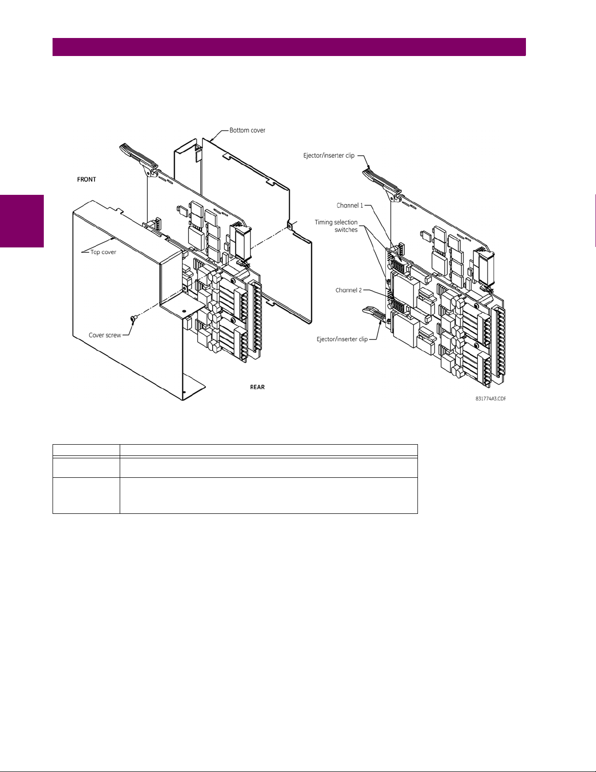
3.3 DIRECT INPUT/OUTPUT COMMUNICATIONS 3 HARDWARE
7. Re-insert the G.703 module. Take care to ensure that the correct module type is inserted into the correct slot position.
The ejector/inserter clips located at the top and at the bottom of each module must be in the disengaged position as
the module is smoothly inserted into the slot. Once the clips have cleared the raised edge of the chassis, engage the
clips simultaneously. When the clips have locked into position, the module is fully inserted.
3
Figure 3–32: G.703 TIMING SELECTION SWITCH SETTING
Table 3–4: G.703 TIMING SELECTIONS
SWITCHES FUNCTION
S1 OFF octet timing disabled
S5 and S6 S5 = OFF and S6 = OFF loop timing mode
c) G.703 OCTET TIMING
If octet timing is enabled (ON), this 8 kHz signal is asserted during the violation of bit 8 (LSB) necessary for connecting to
higher order systems. When B90s are connected back-to-back, octet timing is disabled (OFF).
d) G.703 TIMING MODES
There are two timing modes for the G.703 module: internal timing mode and loop timing mode (default).
• Internal Timing Mode: The system clock is generated internally. Therefore, the G.703 timing selection should be in
the internal timing mode for back-to-back (UR-to-UR) connections. For back-to-back connections, set for octet timing
(S1 = OFF) and timing mode to internal timing (S5 = ON and S6 = OFF).
• Loop Timing Mode: The system clock is derived from the received line signal. Therefore, the G.703 timing selection
should be in loop timing mode for connections to higher order systems. For connection to a higher order system (URto-multiplexer, factory defaults), set to octet timing (S1 = ON) and set timing mode to loop timing (S5 = OFF and S6 =
OFF).
ON octet timing 8 kHz
S5 = ON and S6 = OFF internal timing mode
S5 = OFF and S6 = ON minimum remote loopback mode
S5 = ON and S6 = ON dual loopback mode
3-30 B90 Low Impedance Bus Differential System GE Multilin
Page 77

3 HARDWARE 3.3 DIRECT INPUT/OUTPUT COMMUNICATIONS
DMR
DMX
G7X
G7R
DMR = Differential Manchester Receiver
DMX = Differential Manchester Transmitter
G7X = G.703 Transmitter
G7R = G.703 Receiver
842774A1.CDR
DMR
DMX
G7X
G7R
DMR = Differential Manchester Receiver
DMX = Differential Manchester Transmitter
G7X = G.703 Transmitter
G7R = G.703 Receiver
842775A1.CDR
The switch settings for the internal and loop timing modes are shown below:
e) G.703 TEST MODES
In minimum remote loopback mode, the multiplexer is enabled to return the data from the external interface without any
processing to assist in diagnosing G.703 line-side problems irrespective of clock rate. Data enters from the G.703 inputs,
passes through the data stabilization latch which also restores the proper signal polarity, passes through the multiplexer
and then returns to the transmitter. The differential received data is processed and passed to the G.703 transmitter module
after which point the data is discarded. The G.703 receiver module is fully functional and continues to process data and
passes it to the differential Manchester transmitter module. Since timing is returned as it is received, the timing source is
expected to be from the G.703 line side of the interface.
3
Figure 3–33: G.703 MINIMUM REMOTE LOOPBACK MODE
In dual loopback mode, the multiplexers are active and the functions of the circuit are divided into two with each receiver/
transmitter pair linked together to deconstruct and then reconstruct their respective signals. Differential Manchester data
enters the Differential Manchester receiver module and then is returned to the differential Manchester transmitter module.
Likewise, G.703 data enters the G.703 receiver module and is passed through to the G.703 transmitter module to be
returned as G.703 data. Because of the complete split in the communications path and because, in each case, the clocks
are extracted and reconstructed with the outgoing data, in this mode there must be two independent sources of timing. One
source lies on the G.703 line side of the interface while the other lies on the differential Manchester side of the interface.
Figure 3–34: G.703 DUAL LOOPBACK MODE
GE Multilin B90 Low Impedance Bus Differential System 3-31
Page 78

3.3 DIRECT INPUT/OUTPUT COMMUNICATIONS 3 HARDWARE
~
~
~
~
~
~
~
~
~
~
~
~
~
~
Shield
Shield
COM
Tx +
Tx +
Tx –
Tx –
Rx –
Rx –
Rx +
Rx +
3b
5b
2a
4a
6a
7b
8b
Clock
RS422
channel 1
RS422
channel 2
Surge
3a
5a
4b
6b
7a
2b
8a
Inter-relay communications 7W
842776A3.CDR
Dual-channel RS422 module
~
~
~
~
~
Shield
Tx +
Tx –
Rx –
Rx +
3b
2a
6a
RS422
3a
4b
~
~
~
~
COM
8b
Clock
Surge
7a
2b
8a
Inter-relay comms. 7T
Single-channel RS422 module
~ indicates the slot position
3.3.5 RS422 INTERFACE
a) DESCRIPTION
There are two RS422 inter-relay communications modules available: single-channel RS422 (module 7T) and dual-channel
RS422 (module 7W). The modules can be configured to run at 64 kbps or 128 kbps. AWG 20-24 twisted shielded pair cable
is recommended for external connections. These modules are protected by optically-isolated surge suppression devices.
The shield pins (6a and 7b) are internally connected to the ground pin (8a). Proper shield termination is as follows:
• Site 1: Terminate shield to pins 6a or 7b or both.
• Site 2: Terminate shield to COM pin 2b.
Match the clock terminating impedance with the impedance of the line.
3
The following figure shows the typical pin interconnection between two single-channel RS422 interfaces installed in slot W.
All pin interconnections are to be maintained for a connection to a multiplexer.
b) TWO-CHANNEL APPLICATION VIA MULTIPLEXERS
The RS422 interface can be used for single channel or two channel applications over SONET/SDH or multiplexed systems.
When used in single-channel applications, the RS422 interface links to higher order systems in a typical fashion observing
transmit (Tx), receive (Rx), and send timing (ST) connections. However, when used in two-channel applications, certain criteria must be followed since there is one clock input for the two RS422 channels. The system functions correctly when the
following connections are observed and your data module has a terminal timing feature. Terminal timing is a common feature to most synchronous data units that allows the module to accept timing from an external source. Using the terminal
timing feature, two channel applications can be achieved if these connections are followed: The send timing outputs from
the multiplexer (data module 1), connects to the clock inputs of the UR–RS422 interface in the usual fashion. In addition,
the send timing outputs of data module 1 is also paralleled to the terminal timing inputs of data module 2. By using this configuration, the timing for both data modules and both UR–RS422 channels are derived from a single clock source. As a
result, data sampling for both of the UR–RS422 channels is synchronized via the send timing leads on data module 1 as
shown below. If the terminal timing feature is not available or this type of connection is not desired, the G.703 interface is a
viable option that does not impose timing restrictions.
3-32 B90 Low Impedance Bus Differential System GE Multilin
Figure 3–35: RS422 INTERFACE CONNECTIONS
Figure 3–36: TYPICAL PIN INTERCONNECTION BETWEEN TWO RS422 INTERFACES
Page 79
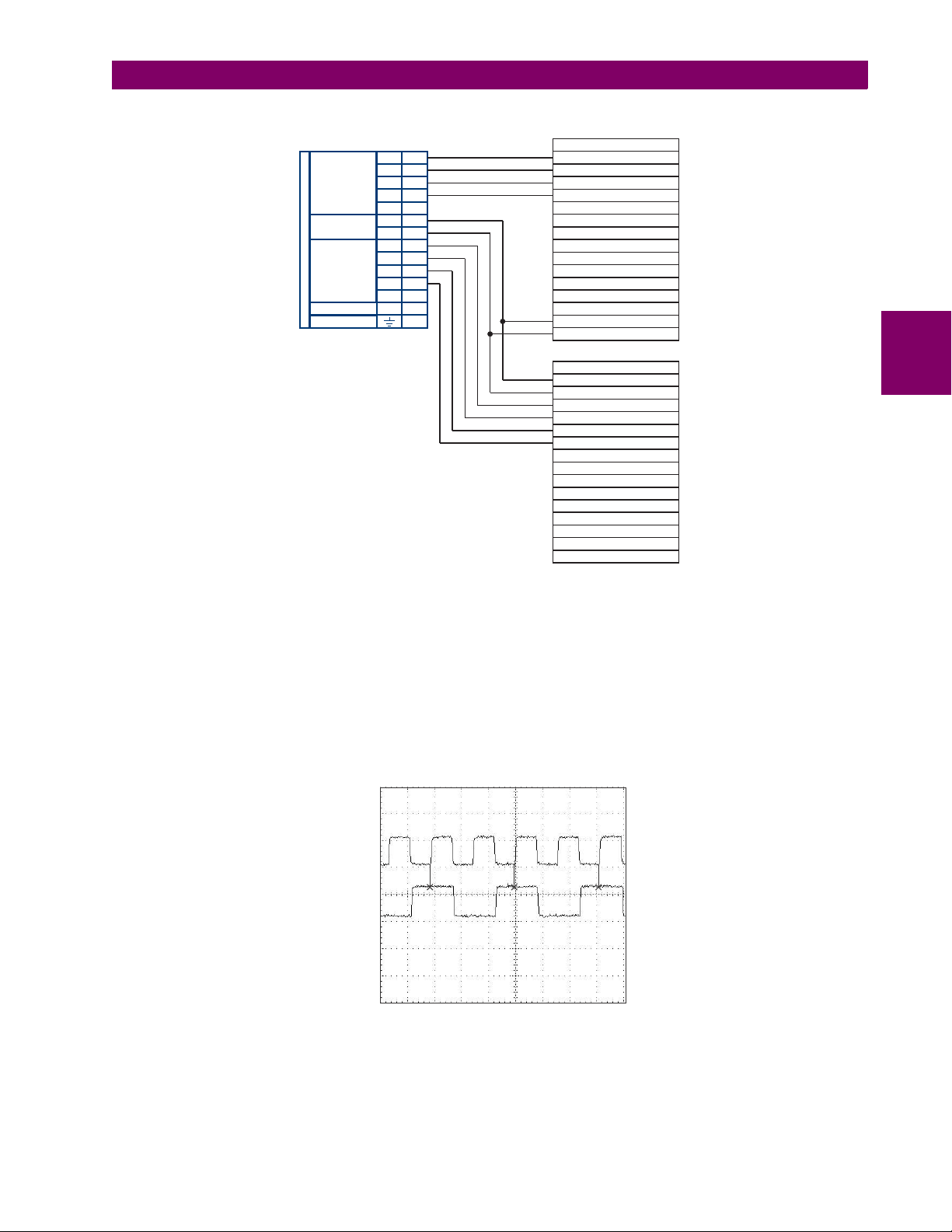
3 HARDWARE 3.3 DIRECT INPUT/OUTPUT COMMUNICATIONS
Data module 1
Data module 2
Signal name
Signal name
SD(A) - Send data
TT(A) - Terminal timing
TT(B) - Terminal timing
SD(B) - Send data
RD(A) - Received data
RD(A) - Received data
SD(A) - Send data
SD(B) - Send data
RD(B) - Received data
RD(B) - Received data
RS(A) - Request to send (RTS)
RS(A) - Request to send (RTS)
RT(A) - Receive timing
CS(A) - Clear To send
CS(A) - Clear To send
RT(B) - Receive timing
CS(B) - Clear To send
CS(B) - Clear To send
Local loopback
Local loopback
Remote loopback
Remote loopback
Signal ground
Signal ground
ST(A) - Send timing
ST(A) - Send timing
ST(B) - Send timing
ST(B) - Send timing
RS(B) - Request to send (RTS)
RS(B) - Request to send (RTS)
831022A3.CDR
W
7a
W
2b
W
8a
7W
Shld.
Shld.
Tx1(+)
Tx2(+)
Tx1(-)
Tx2(-)
Rx1(+)
Rx2(+)
+
com
Rx1(-)
Rx2(-)
–
INTER-RELAY COMMUNICATIONS
W
3a
W
5b
W
5a
W
3b
W
2a
W
6a
W
6b
W
7b
W
8b
W
4b
W
4a
RS422
CHANNEL 1
RS422
CHANNEL 2
CLOCK
SURGE
Tx Clock
Tx Data
3
Figure 3–37: TIMING CONFIGURATION FOR RS422 TWO-CHANNEL, 3-TERMINAL APPLICATION
Data module 1 provides timing to the B90 RS422 interface via the ST(A) and ST(B) outputs. Data module 1 also provides
timing to data module 2 TT(A) and TT(B) inputs via the ST(A) and AT(B) outputs. The data module pin numbers have been
omitted in the figure above since they vary by manufacturer.
c) TRANSMIT TIMING
The RS422 interface accepts one clock input for transmit timing. It is important that the rising edge of the 64 kHz transmit
timing clock of the multiplexer interface is sampling the data in the center of the transmit data window. Therefore, it is important to confirm clock and data transitions to ensure proper system operation. For example, the following figure shows the
positive edge of the Tx clock in the center of the Tx data bit.
d) RECEIVE TIMING
The RS422 interface utilizes NRZI-MARK modulation code and; therefore, does not rely on an Rx clock to recapture data.
NRZI-MARK is an edge-type, invertible, self-clocking code.
GE Multilin B90 Low Impedance Bus Differential System 3-33
Figure 3–38: CLOCK AND DATA TRANSITIONS
Page 80

3.3 DIRECT INPUT/OUTPUT COMMUNICATIONS 3 HARDWARE
To recover the Rx clock from the data-stream, an integrated DPLL (digital phase lock loop) circuit is utilized. The DPLL is
driven by an internal clock, which is 16-times over-sampled, and uses this clock along with the data-stream to generate a
data clock that can be used as the SCC (serial communication controller) receive clock.
3.3.6 RS422 AND FIBER INTERFACE
The following figure shows the combined RS422 plus fiberoptic interface configuration at 64K baud. The 7L, 7M, 7N, 7P,
and 74 modules are used in two-terminal with a redundant channel or three-terminal configurations where channel 1 is
employed via the RS422 interface (possibly with a multiplexer) and channel 2 via direct fiber.
AWG 20-24 twisted shielded pair is recommended for external RS422 connections and ground the shield only at one end.
For the direct fiber channel, address power budget issues properly.
When using a LASER Interface, attenuators can be necessary to ensure that you do not exceed
3
maximum optical input power to the receiver.
Figure 3–39: RS422 AND FIBER INTERFACE CONNECTION
Connections shown above are for multiplexers configured as DCE (data communications equipment) units.
3.3.7 G.703 AND FIBER INTERFACE
The figure below shows the combined G.703 plus fiberoptic interface configuration at 64 kbps. The 7E, 7F, 7G, 7Q, and 75
modules are used in configurations where channel 1 is employed via the G.703 interface (possibly with a multiplexer) and
channel 2 via direct fiber. AWG 24 twisted shielded pair is recommended for external G.703 connections connecting the
shield to pin 1a at one end only. For the direct fiber channel, address power budget issues properly. See previous sections
for additional details on the G.703 and fiber interfaces.
When using a laser Interface, attenuators can be necessary to ensure that you do not exceed the
maximum optical input power to the receiver.
Figure 3–40: G.703 AND FIBER INTERFACE CONNECTION
3-34 B90 Low Impedance Bus Differential System GE Multilin
Page 81

3 HARDWARE 3.3 DIRECT INPUT/OUTPUT COMMUNICATIONS
3.3.8 IEEE C37.94 INTERFACE
The UR-series IEEE C37.94 communication modules (modules types 2G, 2H, 76, and 77) are designed to interface with
IEEE C37.94 compliant digital multiplexers or an IEEE C37.94 compliant interface converter for use with direct input and
output applications. The IEEE C37.94 standard defines a point-to-point optical link for synchronous data between a multiplexer and a teleprotection device. This data is typically 64 kbps, but the standard provides for speeds up to 64n kbps,
where n = 1, 2,…, 12. The UR-series C37.94 communication modules are either 64 kbps (with n fixed at 1) for 128 kbps
(with n fixed at 2). The frame is a valid International Telecommunications Union (ITU-T) recommended G.704 pattern from
the standpoint of framing and data rate. The frame is 256 bits and is repeated at a frame rate of 8000 Hz, with a resultant bit
rate of 2048 kbps.
The specifications for the module are as follows:.
• IEEE standard: C37.94 for 1 128 kbps optical fiber interface (for 2G and 2H modules) or C37.94 for 2 64 kbps opti-
cal fiber interface (for 76 and 77 modules)
• Fiber optic cable type: 50 mm or 62.5 mm core diameter optical fiber
• Fiber optic mode: multi-mode
• Fiber optic cable length: up to 2 km
• Fiber optic connector: type ST
• Wavelength: 830 ±40 nm
• Connection: as per all fiber optic connections, a Tx to Rx connection is required
The UR-series C37.94 communication module can be connected directly to any compliant digital multiplexer that supports
the IEEE C37.94 standard as shown below.
3
The UR-series C37.94 communication module can be connected to the electrical interface (G.703, RS422, or X.21) of a
non-compliant digital multiplexer via an optical-to-electrical interface converter that supports the IEEE C37.94 standard, as
shown below.
The UR-series C37.94 communication module has six (6) switches that are used to set the clock configuration. The functions of these control switches are shown below.
GE Multilin B90 Low Impedance Bus Differential System 3-35
Page 82

3.3 DIRECT INPUT/OUTPUT COMMUNICATIONS 3 HARDWARE
For the internal timing mode, the system clock is generated internally. Therefore, the timing switch selection should be
internal timing for relay 1 and loop timed for relay 2. There must be only one timing source configured.
For the looped timing mode, the system clock is derived from the received line signal. Therefore, the timing selection
should be in loop timing mode for connections to higher order systems.
The IEEE C37.94 communications module cover removal procedure is as follows:
1. With power to the relay off, remove the IEEE C37.94 module (type 2G, 2H, 76 or 77 module) as follows. Record the
original location of the module to help ensure that the same or replacement module is inserted into the correct slot.
2. Simultaneously pull the ejector/inserter clips located at the top and at the bottom of each module in order to release the
module for removal.
3. Remove the module cover screw.
4. Remove the top cover by sliding it towards the rear and then lift it upwards.
3
5. Set the timing selection switches (channel 1, channel 2) to the desired timing modes (see description above).
6. Replace the top cover and the cover screw.
7. Re-insert the IEEE C37.94 module. Take care to ensure that the correct module type is inserted into the correct slot
position. The ejector/inserter clips located at the top and at the bottom of each module must be in the disengaged position as the module is smoothly inserted into the slot. Once the clips have cleared the raised edge of the chassis,
engage the clips simultaneously. When the clips have locked into position, the module is fully inserted.
Figure 3–41: IEEE C37.94 TIMING SELECTION SWITCH SETTING
3-36 B90 Low Impedance Bus Differential System GE Multilin
Page 83
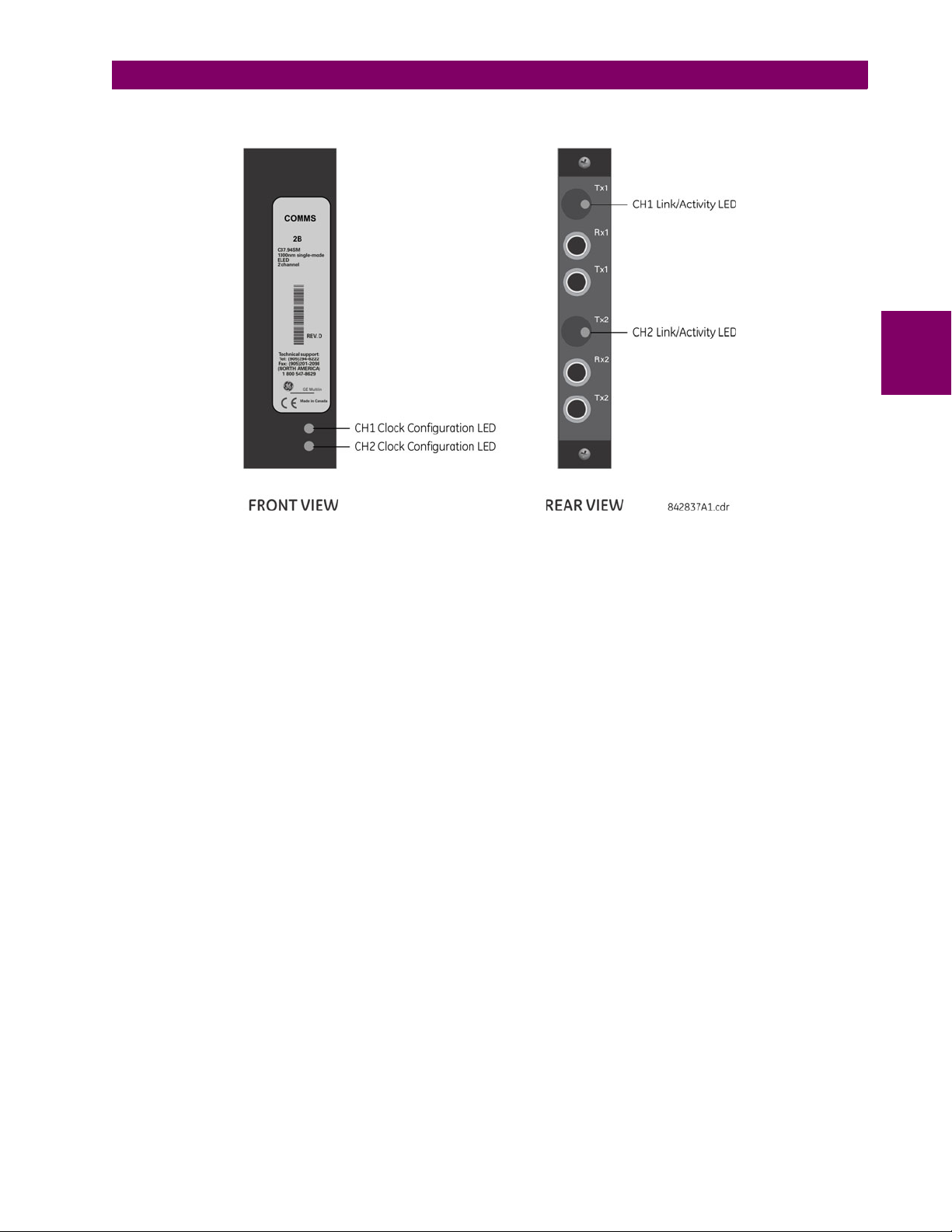
3 HARDWARE 3.3 DIRECT INPUT/OUTPUT COMMUNICATIONS
Modules shipped since January 2012 have status LEDs that indicate the status of the DIP switches, as shown in the following figure.
3
Figure 3–42: STATUS LEDS
The clock configuration LED status is as follows:
• Flashing green — loop timing mode while receiving a valid data packet
• Flashing yellow — internal mode while receiving a valid data packet
• Solid red — (switch to) internal timing mode while not receiving a valid data packet
The link/activity LED status is as follows:
• Flashing green — FPGA is receiving a valid data packet
• Solid yellow — FPGA is receiving a "yellow bit" and remains yellow for each "yellow bit"
• Solid red — FPGA is not receiving a valid packet or the packet received is invalid
GE Multilin B90 Low Impedance Bus Differential System 3-37
Page 84

3.3 DIRECT INPUT/OUTPUT COMMUNICATIONS 3 HARDWARE
3.3.9 C37.94SM INTERFACE
The UR-series C37.94SM communication modules (2A and 2B) are designed to interface with modified IEEE C37.94 compliant digital multiplexers or IEEE C37.94 compliant interface converters that have been converted from 820 nm multi-mode
fiber optics to 1300 nm ELED single-mode fiber optics. The IEEE C37.94 standard defines a point-to-point optical link for
synchronous data between a multiplexer and a teleprotection device. This data is typically 64 kbps, but the standard provides for speeds up to 64n kbps, where n = 1, 2,…, 12. The UR-series C37.94SM communication module is 64 kbps only
with n fixed at 1. The frame is a valid International Telecommunications Union (ITU-T) recommended G.704 pattern from
the standpoint of framing and data rate. The frame is 256 bits and is repeated at a frame rate of 8000 Hz, with a resultant bit
rate of 2048 kbps.
The specifications for the module are as follows:
• Emulated IEEE standard: emulates C37.94 for 1 64 kbps optical fiber interface (modules set to n = 1 or 64 kbps)
• Fiber optic cable type: 9/125 m core diameter optical fiber
3
• Fiber optic mode: single-mode, ELED compatible with HP HFBR-1315T transmitter and HP HFBR-2316T receiver
• Fiber optic cable length: up to 11.4 km
• Fiber optic connector: type ST
• Wavelength: 1300 ±40 nm
• Connection: as per all fiber optic connections, a Tx to Rx connection is required
The UR-series C37.94SM communication module can be connected directly to any compliant digital multiplexer that supports C37.94SM as shown below.
It can also can be connected directly to any other UR-series relay with a C37.94SM module as shown below.
The UR-series C37.94SM communication module has six switches that are used to set the clock configuration. The functions of these control switches are shown below.
For the internal timing mode, the system clock is generated internally. Therefore, the timing switch selection should be
internal timing for relay 1 and loop timed for relay 2. There must be only one timing source configured.
3-38 B90 Low Impedance Bus Differential System GE Multilin
Page 85
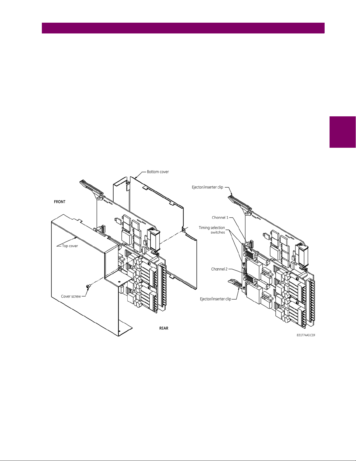
3 HARDWARE 3.3 DIRECT INPUT/OUTPUT COMMUNICATIONS
For the looped timing mode, the system clock is derived from the received line signal. Therefore, the timing selection
should be in loop timing mode for connections to higher order systems.
The C37.94SM communications module cover removal procedure is as follows:
1. With power to the relay off, remove the C37.94SM module (modules 2A or 2B) as follows. Record the original location
of the module to help ensure that the same or replacement module is inserted into the correct slot.
2. Simultaneously pull the ejector/inserter clips located at the top and at the bottom of each module in order to release the
module for removal.
3. Remove the module cover screw.
4. Remove the top cover by sliding it towards the rear and then lift it upwards.
5. Set the timing selection switches (channel 1, channel 2) to the desired timing modes (see description above).
6. Replace the top cover and the cover screw.
7. Re-insert the C37.94SM module. Take care to ensure that the correct module type is inserted into the correct slot
position. The ejector/inserter clips located at the top and at the bottom of each module must be in the disengaged position as the module is smoothly inserted into the slot. Once the clips have cleared the raised edge of the chassis,
engage the clips simultaneously. When the clips have locked into position, the module is fully inserted.
3
Figure 3–43: C37.94SM TIMING SELECTION SWITCH SETTING
GE Multilin B90 Low Impedance Bus Differential System 3-39
Page 86
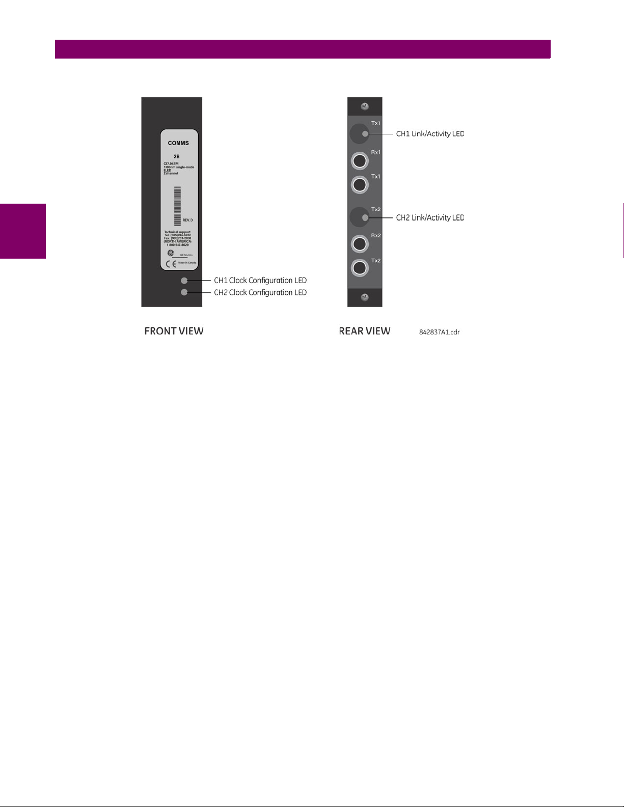
3.3 DIRECT INPUT/OUTPUT COMMUNICATIONS 3 HARDWARE
Modules shipped since January 2012 have status LEDs that indicate the status of the DIP switches, as shown in the following figure.
3
Figure 3–44: STATUS LEDS
The clock configuration LED status is as follows:
• Flashing green — loop timing mode while receiving a valid data packet
• Flashing yellow — internal mode while receiving a valid data packet
• Solid red — (switch to) internal timing mode while not receiving a valid data packet
The link/activity LED status is as follows:
• Flashing green — FPGA is receiving a valid data packet
• Solid yellow — FPGA is receiving a "yellow bit" and remains yellow for each "yellow bit"
• Solid red — FPGA is not receiving a valid packet or the packet received is invalid
3-40 B90 Low Impedance Bus Differential System GE Multilin
Page 87

4 HUMAN INTERFACES 4.1 ENERVISTA UR SETUP SOFTWARE INTERFACE
4 HUMAN INTERFACES 4.1ENERVISTA UR SETUP SOFTWARE INTERFACE 4.1.1 INTRODUCTION
The EnerVista UR Setup software provides a graphical user interface (GUI) as one of two human interfaces to a UR device.
The alternate human interface is implemented via the device’s faceplate keypad and display (see the Faceplate interface
section in this chapter).
The EnerVista UR Setup software provides a single facility to configure, monitor, maintain, and troubleshoot the operation
of relay functions, connected over local or wide area communication networks. It can be used while disconnected (offline)
or connected (online) to a UR device. In offline mode, settings files can be created for eventual downloading to the device.
In online mode, you can communicate with the device in real-time.
The EnerVista UR Setup software, provided with every B90 relay, can be run from any computer supporting Microsoft
dows 95, 98, NT, 2000, ME, and XP. This chapter provides a summary of the basic EnerVista UR Setup software interface
features. The EnerVista UR Setup Help File provides details for getting started and using the EnerVista UR Setup software
interface.
4.1.2 CREATING A SITE LIST
To start using the EnerVista UR Setup software, site and device definition are required. See the EnerVista UR Setup Help
File or refer to the Connecting EnerVista UR Setup with the B90 section in Chapter 1 for details.
4.1.3 ENERVISTA UR SETUP OVERVIEW
a) ENGAGING A DEVICE
The EnerVista UR Setup software can be used in online mode (relay connected) to directly communicate with the B90
relay. Communicating relays are organized and grouped by communication interfaces and into sites. Sites can contain any
number of relays selected from the UR-series of relays.
Win-
4
b) USING SETTINGS FILES
The EnerVista UR Setup software interface supports three ways of handling changes to relay settings:
• In offline mode (relay disconnected) to create or edit relay settings files for later download to communicating relays
• While connected to a communicating relay to directly modify any relay settings via relay data view windows, and then
save the settings to the relay
• You can create/edit settings files and then write them to the relay while the interface is connected to the relay
Settings files are organized on the basis of file names assigned by the user. A settings file contains data pertaining to the
following types of relay settings:
• Device definition
• Product setup
• System setup
• FlexLogic
• Grouped elements
• Control elements
• Inputs/outputs
• Testing
Factory default values are supplied and can be restored after any changes.
The following communications settings are not transferred to the B90 with settings files.
Modbus Slave Address
Modbus IP Port Number
RS485 COM2 Baud Rate
RS485 COM2 Parity
COM2 Minimum Response Time
GE Multilin B90 Low Impedance Bus Differential System 4-1
Page 88

4.1 ENERVISTA UR SETUP SOFTWARE INTERFACE 4 HUMAN INTERFACES
COM2 Selection
RRTD Slave Address
RRTD Baud Rate
IP Address
IP Subnet Mask
Gateway IP Address
Ethernet Sub Module Serial Number
Network Address NSAP
IEC61850 Config GOOSE ConfRev
When a settings file is loaded to a B90 that is in-service, the following sequence occurs:
1. The B90 takes itself out of service.
2. The B90 issues a
3. The B90 closes the critical fail contact.
c) CREATING AND EDITING FLEXLOGIC™
You create or edit a FlexLogic equation in order to customize the relay. You can subsequently view the automatically generated logic diagram.
4
d) VIEWING ACTUAL VALUES
You can view real-time relay data such as input/output status and measured parameters.
UNIT NOT PROGRAMMED major self-test error.
e) VIEWING TRIGGERED EVENTS
While the interface is in either online or offline mode, you can view and analyze data generated by triggered specified
parameters, via one of the following:
• Event recorder
The event recorder captures contextual data associated with the last 1024 events, listed in chronological order from
most recent to oldest.
• Oscillography
The oscillography waveform traces and digital states are used to provide a visual display of power system and relay
operation data captured during specific triggered events.
f) FILE SUPPORT
• Execution: Any EnerVista UR Setup file that is opened launches the application or provides focus to the already
opened application. If the file was a settings file (has a URS extension) that had been removed from the Settings List
tree menu, it is added back to the Settings List tree menu.
• Drag and Drop: The Site List and Settings List control bar windows are each mutually a drag source and a drop target
for device-order-code-compatible files or individual menu items. Also, the Settings List control bar window and any
Windows Explorer directory folder are each mutually a file drag source and drop target.
New files that are dropped into the Settings List window are added to the tree, which is automatically sorted alphabetically with respect to settings file names. Files or individual menu items that are dropped in the selected device menu in
the Site List window are automatically sent to the online communicating device.
g) FIRMWARE UPGRADES
The firmware of a B90 device can be upgraded, locally or remotely, via the EnerVista UR Setup software. The corresponding instructions are provided by the EnerVista UR Setup Help file under the topic “Upgrading Firmware”.
4-2 B90 Low Impedance Bus Differential System GE Multilin
Page 89
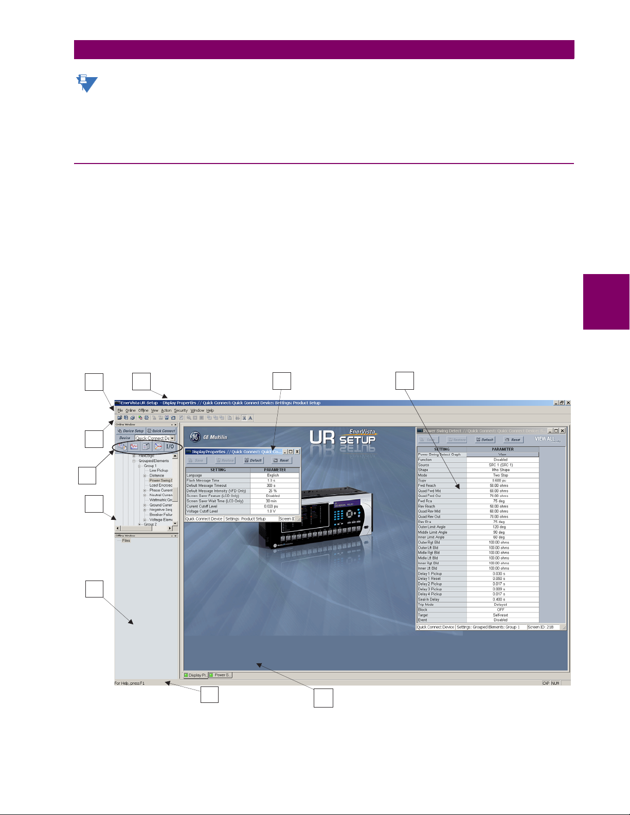
4 HUMAN INTERFACES 4.1 ENERVISTA UR SETUP SOFTWARE INTERFACE
NOTE
1
2
3
4
5
6
7
8
9
842786A2.CDR
10
Modbus addresses assigned to firmware modules, features, settings, and corresponding data items (that is, default
values, minimum/maximum values, data type, and item size) can change slightly from version to version of firmware. The addresses are rearranged when new features are added or existing features are enhanced or modified.
EEPROM DATA ERROR message displayed after upgrading/downgrading the firmware is a resettable, self-test
The
message intended to inform users that the Modbus addresses have changed with the upgraded firmware. This
message does not signal any problems when appearing after firmware upgrades.
4.1.4 ENERVISTA UR SETUP MAIN WINDOW
The EnerVista UR Setup software main window supports the following primary display components:
1. Title bar that shows the pathname of the active data view
2. Main window menu bar
3. Main window tool bar
4. Site list control bar window
5. Settings list control bar window
6. Device data view windows, with common tool bar
7. Settings file data view windows, with common tool bar
8. Workspace area with data view tabs
9. Status bar
10. Quick action hot links
4
Figure 4–1: ENERVISTA UR SETUP SOFTWARE MAIN WINDOW
GE Multilin B90 Low Impedance Bus Differential System 4-3
Page 90

4.2 EXTENDED ENERVISTA UR SETUP FEATURES 4 HUMAN INTERFACES
4.2EXTENDED ENERVISTA UR SETUP FEATURES 4.2.1 SETTINGS TEMPLATES
Setting file templates simplify the configuration and commissioning of multiple relays that protect similar assets. An example of this is a substation that has ten similar feeders protected by ten UR-series F60 relays.
In these situations, typically 90% or greater of the settings are identical between all devices. The templates feature allows
engineers to configure and test these common settings, then lock them so that they are not available to users. For example, these locked down settings can be hidden from view for field engineers, allowing them to quickly identify and concentrate on the specific settings.
The remaining settings (typically 10% or less) can be specified as editable and be made available to field engineers installing the devices. These are settings such as protection element pickup values and CT and VT ratios.
The settings template mode allows the user to define which settings are visible in EnerVista UR Setup. Settings templates
can be applied to both settings files (settings file templates) and online devices (online settings templates). The functionality
is identical for both purposes.
a) ENABLING THE SETTINGS TEMPLATE
The settings file template feature is disabled by default. The following procedure describes how to enable the settings template for UR-series settings files.
1. Select a settings file from the offline window of the EnerVista UR Setup main screen.
4
2. Right-click the selected device or settings file and select the Template Mode > Create Template option.
The settings file template is now enabled and the file tree displayed in light blue. The settings file is now in template editing
mode.
Alternatively, the settings template can also be applied to online settings. The following procedure describes this process.
1. Select an installed device from the online window of the EnerVista UR Setup main screen.
2. Right-click the selected device and select the Template Mode > Create Template option.
The software prompts for a template password. This password is required to use the template feature and must be at
least four characters in length.
3. Enter and re-enter the new password, then click OK to continue.
The online settings template is now enabled. The device is now in template editing mode.
b) EDITING THE SETTINGS TEMPLATE
The settings template editing feature allows the user to specify which settings are available for viewing and modification in
EnerVista UR Setup. By default, all settings except the FlexLogic equation editor settings are locked.
1. Select an installed device or a settings file from the tree menu on the left of the EnerVista UR Setup main screen.
2. Select the Template Mode > Edit Template option to place the device in template editing mode.
3. Enter the template password then click OK.
4. Open the relevant settings windows that contain settings to be specified as viewable.
4-4 B90 Low Impedance Bus Differential System GE Multilin
Page 91

4 HUMAN INTERFACES 4.2 EXTENDED ENERVISTA UR SETUP FEATURES
By default, all settings are specified as locked and displayed against a grey background. The icon on the upper right of
the settings window also indicates that EnerVista UR Setup is in EDIT mode. The following example shows the phase
time overcurrent settings window in edit mode.
Figure 4–2: SETTINGS TEMPLATE VIEW, ALL SETTINGS SPECIFIED AS LOCKED
5. Specify the settings to make viewable by clicking them.
The setting available to view is displayed against a yellow background as shown below.
4
Figure 4–3: SETTINGS TEMPLATE VIEW, TWO SETTINGS SPECIFIED AS EDITABLE
6. Click on Save to save changes to the settings template.
7. Proceed through the settings tree to specify all viewable settings.
c) ADDING PASSWORD PROTECTION TO A TEMPLATE
It is highly recommended that templates be saved with password protection to maximize security.
The following procedure describes how to add password protection to a settings file template.
1. Select a settings file from the offline window on the left of the EnerVista UR Setup main screen.
2. Selecting the Template Mode > Password Protect Template option.
GE Multilin B90 Low Impedance Bus Differential System 4-5
Page 92
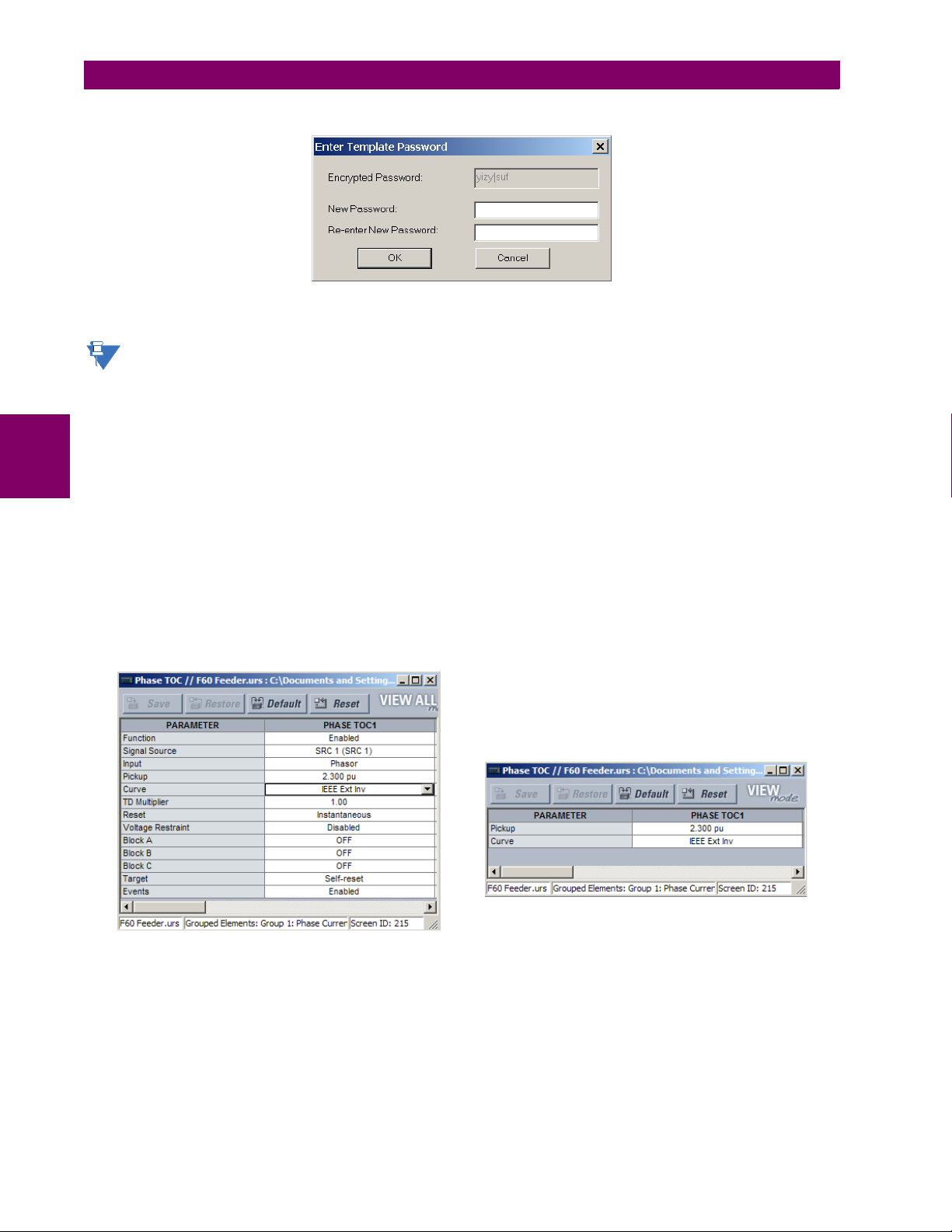
4.2 EXTENDED ENERVISTA UR SETUP FEATURES 4 HUMAN INTERFACES
NOTE
Phase time overcurrent settings window without template applied.
Phase time overcurrent window with template applied via
the command.
The template specifies that only the and
settings be available.
Template Mode > View In Template Mode
Pickup Curve
842858A1.CDR
The software prompts for a template password. This password must be at least four characters in length.
3. Enter and re-enter the new password, then click OK to continue.
The settings file template is now secured with password protection.
When templates are created for online settings, the password is added during the initial template creation step. It
does not need to be added after the template is created.
d) VIEWING THE SETTINGS TEMPLATE
Once all necessary settings are specified for viewing, users are able to view the settings template on the online device or
settings file. There are two ways to specify the settings view with the settings template feature:
4
• Display only those settings available for editing
• Display all settings, with settings not available for editing greyed-out
Use the following procedure to only display settings available for editing:
1. Select an installed device or a settings file from the tree menu on the left of the EnerVista UR Setup main screen.
2. Apply the template by selecting the Template Mode > View In Template Mode option.
3. Enter the template password then click OK to apply the template.
Once the template has been applied, users are limited to view and edit the settings specified by the template. The effect of
applying the template to the phase time overcurrent settings is shown below.
Figure 4–4: APPLYING TEMPLATES VIA THE VIEW IN TEMPLATE MODE COMMAND
4-6 B90 Low Impedance Bus Differential System GE Multilin
Page 93

4 HUMAN INTERFACES 4.2 EXTENDED ENERVISTA UR SETUP FEATURES
Typical settings tree view without template applied. Typical settings tree view with template applied via
the
command.
Template Mode > View In Template Mode
842860A1.CDR
Phase time overcurrent settings window without template applied. Phase time overcurrent window with template applied via
the command.
The template specifies that only the and
settings be available.
Template Mode > View All Settings
Pickup Curve
842859A1.CDR
Viewing the settings in template mode also modifies the settings tree, showing only the settings categories that contain
editable settings. The effect of applying the template to a typical settings tree view is shown below.
Figure 4–5: APPLYING TEMPLATES VIA THE VIEW IN TEMPLATE MODE SETTINGS COMMAND
Use the following procedure to display settings available for editing and settings locked by the template.
1. Select an installed device or a settings file from the tree menu on the left of the EnerVista UR Setup main screen.
2. Apply the template by selecting the Template Mode > View All Settings option.
3. Enter the template password then click OK to apply the template.
Once the template has been applied, users are limited to edit the settings specified by the template, but all settings are
shown. The effect of applying the template to the phase time overcurrent settings is shown below.
4
Figure 4–6: APPLYING TEMPLATES VIA THE VIEW ALL SETTINGS COMMAND
e) REMOVING THE SETTINGS TEMPLATE
It can be necessary at some point to remove a settings template. Once a template is removed, it cannot be reapplied and it
is necessary to define a new settings template.
1. Select an installed device or settings file from the tree menu on the left of the EnerVista UR Setup main screen.
2. Select the Template Mode > Remove Settings Template option.
3. Enter the template password and click OK to continue.
GE Multilin B90 Low Impedance Bus Differential System 4-7
Page 94

4.2 EXTENDED ENERVISTA UR SETUP FEATURES 4 HUMAN INTERFACES
4. Verify one more time that you want to remove the template by clicking Yes.
The EnerVista software removes all template information and all settings are available.
4.2.2 SECURING AND LOCKING FLEXLOGIC™ EQUATIONS
The UR allows users to secure parts or all of a FlexLogic equation, preventing unauthorized viewing or modification of critical FlexLogic applications. This is accomplished using the settings template feature to lock individual entries within FlexLogic equations.
Secured FlexLogic equations remain secure when files are sent to and retrieved from any UR-series device.
a) LOCKING FLEXLOGIC™ EQUATION ENTRIES
The following procedure describes how to lock individual entries of a FlexLogic equation.
4
1. Right-click the settings file or online device and select the Template Mode > Create Template item to enable the set-
tings template feature.
2. Select the FlexLogic > FlexLogic Equation Editor settings menu item.
By default, all FlexLogic entries are specified as viewable and displayed against a yellow background. The icon on the
upper right of the window also indicates that EnerVista UR Setup is in EDIT mode.
3. Specify which entries to lock by clicking on them.
The locked entries are displayed against a grey background as shown in the example below.
Figure 4–7: LOCKING FLEXLOGIC ENTRIES IN EDIT MODE
4. Click on Save to save and apply changes to the settings template.
5. Select the Template Mode > View In Template Mode option to view the template.
6. Apply a password to the template then click OK to secure the FlexLogic equation.
4-8 B90 Low Impedance Bus Differential System GE Multilin
Page 95
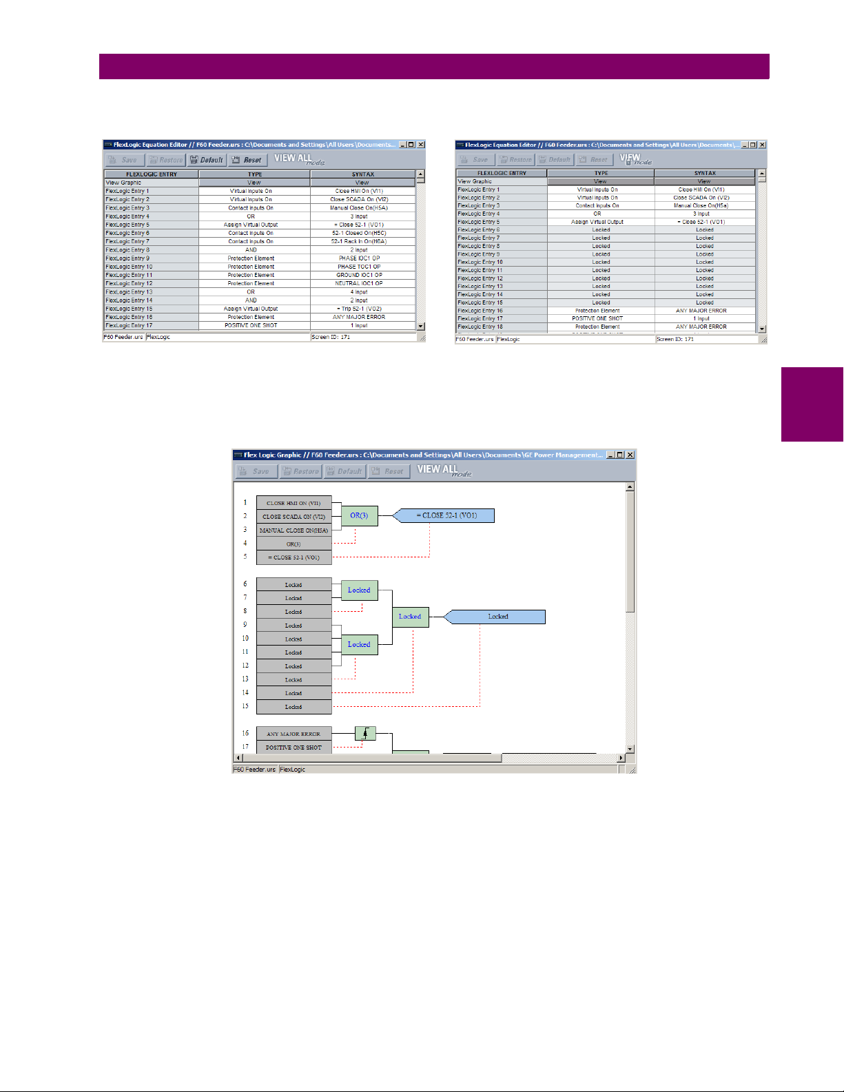
4 HUMAN INTERFACES 4.2 EXTENDED ENERVISTA UR SETUP FEATURES
Typical FlexLogic™ entries without template applied. Typical locked with template via
the command.Template Mode > View In Template Mode
FlexLogic™ entries
842861A1.CDR
Once the template has been applied, users are limited to view and edit the FlexLogic entries not locked by the template.
The effect of applying the template to the FlexLogic entries in the above procedure is shown below.
Figure 4–8: LOCKING FLEXLOGIC ENTRIES THROUGH SETTING TEMPLATES
The FlexLogic entries are also shown as locked in the graphical view (as shown below) and on the front panel display.
Figure 4–9: SECURED FLEXLOGIC IN GRAPHICAL VIEW
4
b) LOCKING FLEXLOGIC™ EQUATIONS TO A SERIAL NUMBER
A settings file and associated FlexLogic equations can also be locked to a specific UR serial number. Once the desired
FlexLogic entries in a settings file have been secured, use the following procedure to lock the settings file to a specific serial
number.
1. Select the settings file in the offline window.
2. Right-click on the file and select the Edit Settings File Properties item.
GE Multilin B90 Low Impedance Bus Differential System 4-9
Page 96

4.2 EXTENDED ENERVISTA UR SETUP FEATURES 4 HUMAN INTERFACES
The following window is displayed.
Figure 4–10: TYPICAL SETTINGS FILE PROPERTIES WINDOW
3. Enter the serial number of the B90 device to lock to the settings file in the Serial # Lock field.
4
The settings file and corresponding secure FlexLogic equations are now locked to the B90 device specified by the serial
number.
4.2.3 SETTINGS FILE TRACEABILITY
A traceability feature for settings files allows the user to quickly determine if the settings in a B90 device have been
changed since the time of installation from a settings file. When a settings file is transferred to a B90 device, the date, time,
and serial number of the B90 are sent back to EnerVista UR Setup and added to the settings file on the local PC. This information can be compared with the B90 actual values at any later date to determine if security has been compromised.
The traceability information is only included in the settings file if a complete settings file is either transferred to the B90
device or obtained from the B90 device. Any partial settings transfers by way of drag and drop do not add the traceability
information to the settings file.
Figure 4–11: SETTINGS FILE TRACEABILITY MECHANISM
With respect to the above diagram, the traceability feature is used as follows.
4-10 B90 Low Impedance Bus Differential System GE Multilin
Page 97
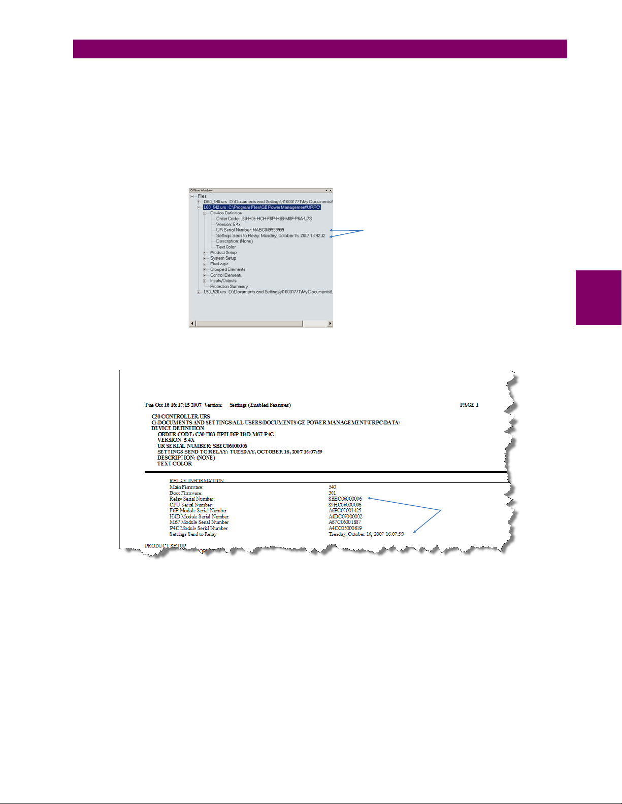
4 HUMAN INTERFACES 4.2 EXTENDED ENERVISTA UR SETUP FEATURES
Traceability data in settings
file device definition
842863A1.CDR
Traceability data
in settings report
842862A1.CDR
1. The transfer date of a setting file written to a B90 is logged in the relay and can be viewed via EnerVista UR Setup or
the front panel display. Likewise, the transfer date of a setting file saved to a local PC is logged in EnerVista UR Setup.
2. Comparing the dates stored in the relay and on the settings file at any time in the future indicates if any changes have
been made to the relay configuration since the settings file was saved.
a) SETTINGS FILE TRACEABILITY INFORMATION
The serial number and file transfer date are saved in the settings files when they are sent to an B90 device.
The B90 serial number and file transfer date are included in the settings file device definition within the EnerVista UR Setup
offline window as shown in the example below.
Figure 4–12: DEVICE DEFINITION SHOWING TRACEABILITY DATA
This information is also available in printed settings file reports as shown in the example below.
4
Figure 4–13: SETTINGS FILE REPORT SHOWING TRACEABILITY DATA
GE Multilin B90 Low Impedance Bus Differential System 4-11
Page 98
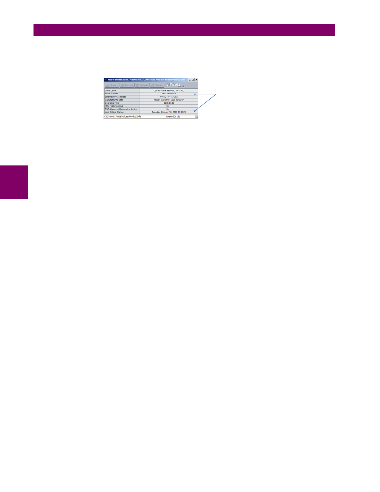
4.2 EXTENDED ENERVISTA UR SETUP FEATURES 4 HUMAN INTERFACES
Traceability data in online
device actual values page
842865A1.CDR
b) ONLINE DEVICE TRACEABILITY INFORMATION
The B90 serial number and file transfer date are available for an online device through the actual values. Select the Actual
Values > Product Info > Model Information menu item within the EnerVista UR Setup online window as shown in the
example below.
Figure 4–14: TRACEABILITY DATA IN ACTUAL VALUES WINDOW
This information if also available from the front panel display through the following actual values:
ACTUAL VALUES PRODUCT INFO MODEL INFORMATION SERIAL NUMBER
ACTUAL VALUES PRODUCT INFO MODEL INFORMATION LAST SETTING CHANGE
c) ADDITIONAL TRACEABILITY RULES
The following additional rules apply for the traceability feature
4
• If the user changes any settings within the settings file in the offline window, then the traceability information is
removed from the settings file.
• If the user creates a new settings file, then no traceability information is included in the settings file.
• If the user converts an existing settings file to another revision, then any existing traceability information is removed
from the settings file.
• If the user duplicates an existing settings file, then any traceability information is transferred to the duplicate settings
file.
4-12 B90 Low Impedance Bus Differential System GE Multilin
Page 99

4 HUMAN INTERFACES 4.3 FACEPLATE INTERFACE
Five column LED indicator panel
Display
User-programmable pushbuttons 1 to 16
842810A1.CDR
Keypad
Front panel
RS232 port
LED panel 1 LED panel 2
Display
User-programmable
pushbuttons 1 to 12
Keypad
Front panel
RS232 port
Small user-programmable
(control) pushbuttons 1 to 7
LED panel 3
827801A7.CDR
4.3FACEPLATE INTERFACE 4.3.1 FACEPLATE
a) ENHANCED FACEPLATE
The front panel interface is one of two supported interfaces, the other interface being EnerVista UR Setup software. The
front panel interface consists of LED panels, an RS232 port, keypad, LCD display, control pushbuttons, and optional userprogrammable pushbuttons.
The faceplate is hinged to allow easy access to the removable modules.
4
Figure 4–15: UR-SERIES ENHANCED FACEPLATE
b) STANDARD FACEPLATE
The front panel interface is one of two supported interfaces, the other interface being EnerVista UR Setup software. The
front panel interface consists of LED panels, an RS232 port, keypad, LCD display, control pushbuttons, and optional userprogrammable pushbuttons.
The faceplate is hinged to allow easy access to the removable modules. There is also a removable dust cover that fits over
the faceplate that must be removed in order to access the keypad panel. The following figure shows the horizontal arrangement of the faceplate panels.
Figure 4–16: UR-SERIES STANDARD HORIZONTAL FACEPLATE PANELS
GE Multilin B90 Low Impedance Bus Differential System 4-13
Page 100

4.3 FACEPLATE INTERFACE 4 HUMAN INTERFACES
842811A1.CDR
4.3.2 LED INDICATORS
a) ENHANCED FACEPLATE
The enhanced front panel display provides five columns of LED indicators. The first column contains 14 status and event
cause LEDs, and the next four columns contain the 48 user-programmable LEDs.
The RESET key is used to reset any latched LED indicator or target message, once the condition has been cleared (these
latched conditions can also be reset via the
intended for connection to a portable PC.
The USER keys are not used in this unit.
SETTINGS INPUT/OUTPUTS RESETTING menu). The RS232 port is
4
Figure 4–17: TYPICAL LED INDICATOR PANEL FOR ENHANCED FACEPLATE
The status indicators in the first column are described below.
• IN SERVICE: This LED indicates that control power is applied, all monitored inputs, outputs, and internal systems are
OK, and that the device has been programmed.
• TROUBLE: This LED indicates that the relay has detected an internal problem.
• TEST MODE: This LED indicates that the relay is in test mode.
• TRIP: This LED indicates that the FlexLogic operand serving as a trip switch has operated. This indicator always
latches; as such, a reset command must be initiated to allow the latch to be reset.
• ALARM: This LED indicates that the FlexLogic operand serving as an alarm switch has operated. This indicator is
never latched.
• PICKUP: This LED indicates that an element is picked up. This indicator is never latched.
The event cause indicators in the first column are described below.
Events cause LEDs are turned on or off by protection elements that have their respective target setting selected as either
“Enabled” or “Latched”. If a protection element target setting is “Enabled”, then the corresponding event cause LEDs
remain on as long as operate operand associated with the element remains asserted. If a protection element target setting
is “Latched”, then the corresponding event cause LEDs turn on when the operate operand associated with the element is
asserted and remain on until the RESET button on the front panel is pressed after the operand is reset.
All elements that are able to discriminate faulted phases can independently turn off or on the phase A, B or C LEDs. This
includes phase instantaneous overcurrent, phase undervoltage, etc. This means that the phase A, B, and C operate operands for individual protection elements are ORed to turn on or off the phase A, B or C LEDs.
• VOLTAGE: This LED indicates voltage was involved.
• CURRENT: This LED indicates current was involved.
• FREQUENCY: This LED indicates frequency was involved.
• OTHER: This LED indicates a composite function was involved.
• PHASE A: This LED indicates phase A was involved.
• PHASE B: This LED indicates phase B was involved.
• PHASE C: This LED indicates phase C was involved.
4-14 B90 Low Impedance Bus Differential System GE Multilin
 Loading...