

Page 1
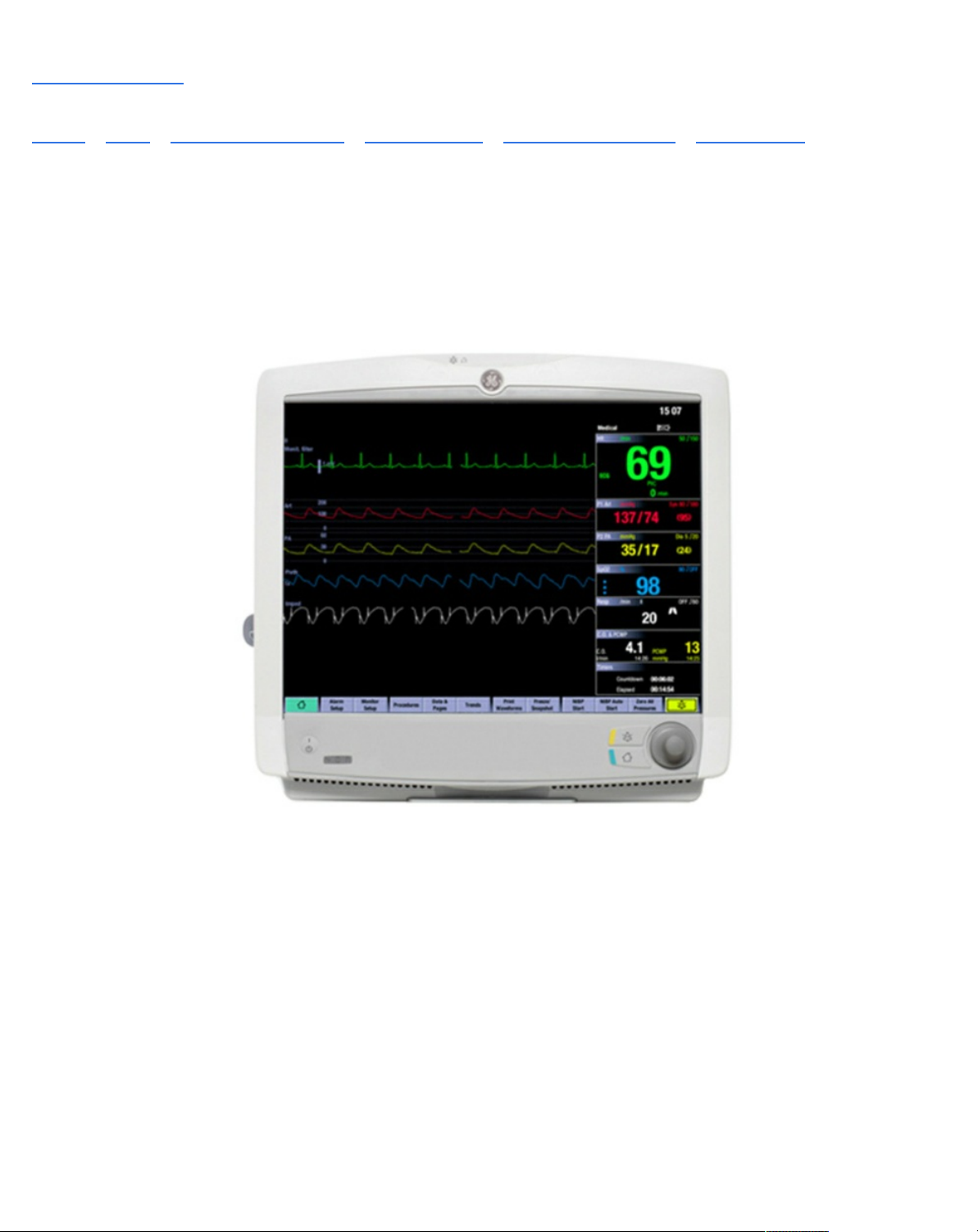
Manuals / Brands / GE HEALTHCARE Manuals / Medical Equipment / CARESCAPE Monitor B650 / Technical manual / PDF
GE HEALTHCARE CARESCAPE MONITOR B650
TECHNICAL MANUAL
Quick Links
Maintenance and Checkout
Error Messages and Codes
Service Parts
Page 2

Table of Contents
Table of Contents
Product naming conventions
Trademarks
Safety symbols
Software
Acquisition modules
CARESCAPE Network IX
Unity Network ID connectivity device
Printers and recorders
Service Interface
Controls and connectors
Side views
Rear views
Service information
Equipment identification
Product security
Security operations
Product change management
Equipment symbols
User interface symbols
Local access to Webmin with a service PC connected to the IX
connector
Local access to Webmin with a service PC connected to the MC
connector
Remote access to Webmin using a service PC over the IX Network
Login to Webmin
Webmin configuration modules
Webmin information modules
Network infrastructure
Page 3

IX Network
Power and environmental requirements
Installing the battery into the patient monitor
Mounting the patient monitor
Connecting a secondary display
Installing parameter modules
Connecting to the mains power
Connecting to the MC Network or the S/5 Network
Connecting USB devices
Connecting a remote-on cable
Configuration
Selecting and configuring CARESCAPE Network
Selecting and configuring S/5 Network
Setting time and date
Setting unit and bed name
Deleting a printer
Admit settings
Barcode settings
Configure character delimited parser information
Barcode data specifications
Setting power frequency
Module asset settings
Restarting the patient monitor
Enabling remote service agent/ connection
Transferring settings from one patient monitor to other patient monitors
Loading settings
Canceling pending settings activation
License management
Uploading license file
Canceling pending host software activation
Power outlet
Earth leakage current test
Page 4

Enclosure leakage current (touch current) test
Patient leakage current tests – overview
Patient (source) leakage current tests
Patient (sink) leakage current tests
Test completion
Display
Keypad and remote
MC Network and S/5 Network
IX printers
Insite with EXC
Main components
CPU subsystem
Display subsystem
External Interfaces
Pivoting module frame
Visual inspection
Electrical safety checks
Alphanumeric keyboard
Test completion
Charging a battery
Battery recycling
Webmin - Information tab
Device information
Webmin - Diagnostics tab
Ping a TCP/IP network device
WLAN diagnostics
Log files
Power management LEDs
Network status LEDs
Battery diagnostics
Error messages and codes
Problems and solutions
Page 5

User interface issues
Incorrect system time
License issues
Recorder issues
CARESCAPE Network communication issues
S/5 Network communication issues
Required tools
Module frame disassembly
Detaching the Recorder Unit
Detaching the PDM docking mechanism
Detaching the Module Frame cover unit
Detaching the E-module Interface Board
Detaching the Module Frame assembly
Main unit disassembly
Detaching the Interface Board
Detaching the Frame Side Housing Decorations
Detaching the Top Cover
Disassembling the main unit into Rear and Front units
Detaching the uDOM
Replacing the CPU timekeeper battery
Detaching the DC/DC board
Detaching the AC/DC board and rear unit assembly
Detaching the Base unit
Front Unit Assembly
Detaching the LCD Display Unit
Replacing the User Interface Board
Replacing the Trim Knob and Trim Knob Encoder
Replacing the Front Unit Assembly FRU
Replacing the WLAN Assembly FRU
Page 6
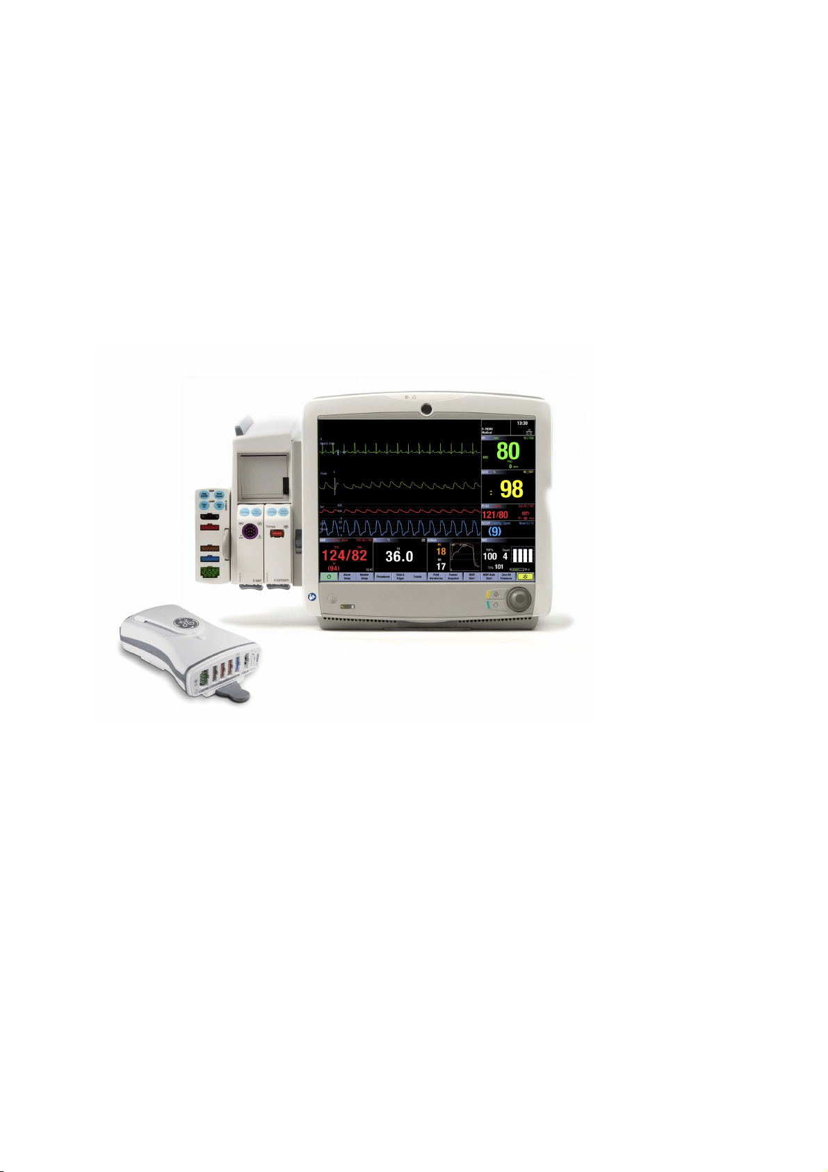
GE Healthcare
CARESCAPE Monitor B650
Technical Manual
Software Version 2
Hardware Version B650 VER02
All specifications subject to change without notice.
English
2081903-001 paper
19 September 2016
© 2016 General Electric Company. All rights reserved.
Page 7

The information in this manual applies to the software and hardware versions listed on the first page of this manual. Due to
continuing product innovation, specifications in this manual are subject to change without notice.
Page 8

Table of contents
Table of contents
1 About this manual 1
1.1 Intended use of the manual . . . . . . . . . . . . . . . . . . . . . . . . . . . . . . . . . . . . . . . . . . . . . . . . . . . . . . . . . . . 1
1.2 Intended audience of the manual. . . . . . . . . . . . . . . . . . . . . . . . . . . . . . . . . . . . . . . . . . . . . . . . . . . . . . 1
1.3 Conventions used in this manual . . . . . . . . . . . . . . . . . . . . . . . . . . . . . . . . . . . . . . . . . . . . . . . . . . . . . . 1
1.3.1 Product naming conventions . . . . . . . . . . . . . . . . . . . . . . . . . . . . . . . . . . . . . . . . . . . . . . . . . . . 2
1.4 Illustrations and names . . . . . . . . . . . . . . . . . . . . . . . . . . . . . . . . . . . . . . . . . . . . . . . . . . . . . . . . . . . . . . . 2
1.5 Ordering manuals. . . . . . . . . . . . . . . . . . . . . . . . . . . . . . . . . . . . . . . . . . . . . . . . . . . . . . . . . . . . . . . . . . . . . 2
1.6 Related documents . . . . . . . . . . . . . . . . . . . . . . . . . . . . . . . . . . . . . . . . . . . . . . . . . . . . . . . . . . . . . . . . . . . 2
1.7 Trademarks . . . . . . . . . . . . . . . . . . . . . . . . . . . . . . . . . . . . . . . . . . . . . . . . . . . . . . . . . . . . . . . . . . . . . . . . . . 3
1.7.1 Third party trademarks . . . . . . . . . . . . . . . . . . . . . . . . . . . . . . . . . . . . . . . . . . . . . . . . . . . . . . . . . 3
1.8 Responsibility of the manufacturer. . . . . . . . . . . . . . . . . . . . . . . . . . . . . . . . . . . . . . . . . . . . . . . . . . . . . 3
1.9 Product availability. . . . . . . . . . . . . . . . . . . . . . . . . . . . . . . . . . . . . . . . . . . . . . . . . . . . . . . . . . . . . . . . . . . . 3
2 Safety information 5
2.1 General safety statements . . . . . . . . . . . . . . . . . . . . . . . . . . . . . . . . . . . . . . . . . . . . . . . . . . . . . . . . . . . . 5
2.2 Safety message signal words. . . . . . . . . . . . . . . . . . . . . . . . . . . . . . . . . . . . . . . . . . . . . . . . . . . . . . . . . . 5
2.3 Safety symbols . . . . . . . . . . . . . . . . . . . . . . . . . . . . . . . . . . . . . . . . . . . . . . . . . . . . . . . . . . . . . . . . . . . . . . . 6
3 System overview 9
3.1 System introduction. . . . . . . . . . . . . . . . . . . . . . . . . . . . . . . . . . . . . . . . . . . . . . . . . . . . . . . . . . . . . . . . . . . 9
3.2 System components . . . . . . . . . . . . . . . . . . . . . . . . . . . . . . . . . . . . . . . . . . . . . . . . . . . . . . . . . . . . . . . . . . 9
3.2.1 Monitor . . . . . . . . . . . . . . . . . . . . . . . . . . . . . . . . . . . . . . . . . . . . . . . . . . . . . . . . . . . . . . . . . . . . . . . . 9
3.2.2 Software . . . . . . . . . . . . . . . . . . . . . . . . . . . . . . . . . . . . . . . . . . . . . . . . . . . . . . . . . . . . . . . . . . . . . . 10
3.2.3 Input devices. . . . . . . . . . . . . . . . . . . . . . . . . . . . . . . . . . . . . . . . . . . . . . . . . . . . . . . . . . . . . . . . . . 10
3.2.4 Acquisition modules . . . . . . . . . . . . . . . . . . . . . . . . . . . . . . . . . . . . . . . . . . . . . . . . . . . . . . . . . . . 12
3.2.5 CARESCAPE Network MC or S/5 Network. . . . . . . . . . . . . . . . . . . . . . . . . . . . . . . . . . . . . . . . 12
3.2.6 CARESCAPE Network IX . . . . . . . . . . . . . . . . . . . . . . . . . . . . . . . . . . . . . . . . . . . . . . . . . . . . . . . . 13
3.2.7 Unity Network ID connectivity device . . . . . . . . . . . . . . . . . . . . . . . . . . . . . . . . . . . . . . . . . . . 14
3.2.8 Secondary display. . . . . . . . . . . . . . . . . . . . . . . . . . . . . . . . . . . . . . . . . . . . . . . . . . . . . . . . . . . . . 14
3.2.9 Printers and recorders . . . . . . . . . . . . . . . . . . . . . . . . . . . . . . . . . . . . . . . . . . . . . . . . . . . . . . . . . 15
3.2.10 Service Interface. . . . . . . . . . . . . . . . . . . . . . . . . . . . . . . . . . . . . . . . . . . . . . . . . . . . . . . . . . . . . . 16
3.3 Controls and connectors . . . . . . . . . . . . . . . . . . . . . . . . . . . . . . . . . . . . . . . . . . . . . . . . . . . . . . . . . . . . . 17
3.3.1 Front view . . . . . . . . . . . . . . . . . . . . . . . . . . . . . . . . . . . . . . . . . . . . . . . . . . . . . . . . . . . . . . . . . . . . 17
3.3.2 Side views . . . . . . . . . . . . . . . . . . . . . . . . . . . . . . . . . . . . . . . . . . . . . . . . . . . . . . . . . . . . . . . . . . . . 18
3.3.3 Rear views . . . . . . . . . . . . . . . . . . . . . . . . . . . . . . . . . . . . . . . . . . . . . . . . . . . . . . . . . . . . . . . . . . . . 19
3.4 Service information . . . . . . . . . . . . . . . . . . . . . . . . . . . . . . . . . . . . . . . . . . . . . . . . . . . . . . . . . . . . . . . . . . 20
3.4.1 Service requirements . . . . . . . . . . . . . . . . . . . . . . . . . . . . . . . . . . . . . . . . . . . . . . . . . . . . . . . . . . 20
3.4.2 Equipment identification. . . . . . . . . . . . . . . . . . . . . . . . . . . . . . . . . . . . . . . . . . . . . . . . . . . . . . . 21
3.5 Product security . . . . . . . . . . . . . . . . . . . . . . . . . . . . . . . . . . . . . . . . . . . . . . . . . . . . . . . . . . . . . . . . . . . . . 22
3.5.1 Security features . . . . . . . . . . . . . . . . . . . . . . . . . . . . . . . . . . . . . . . . . . . . . . . . . . . . . . . . . . . . . . 22
3.5.2 Security operations. . . . . . . . . . . . . . . . . . . . . . . . . . . . . . . . . . . . . . . . . . . . . . . . . . . . . . . . . . . . 23
3.5.3 Product change management . . . . . . . . . . . . . . . . . . . . . . . . . . . . . . . . . . . . . . . . . . . . . . . . . 24
3.5.4 Communication . . . . . . . . . . . . . . . . . . . . . . . . . . . . . . . . . . . . . . . . . . . . . . . . . . . . . . . . . . . . . . . 24
3.6 Equipment symbols . . . . . . . . . . . . . . . . . . . . . . . . . . . . . . . . . . . . . . . . . . . . . . . . . . . . . . . . . . . . . . . . . . 25
i
2081903-001
Page 9

CARESCAPE B650
3.7 User interface symbols . . . . . . . . . . . . . . . . . . . . . . . . . . . . . . . . . . . . . . . . . . . . . . . . . . . . . . . . . . . . . . . 34
4 Using Webmin service interface 39
4.1 Local access to Webmin using the integrated browser on the patient monitor . . . . . . . . . . 39
4.2 Local access to Webmin with a service PC connected to the IX connector . . . . . . . . . . . . . . 40
4.3 Local access to Webmin with a service PC connected to the MC connector. . . . . . . . . . . . . 42
4.4 Remote access to Webmin using a service PC over the IX Network . . . . . . . . . . . . . . . . . . . . . 43
4.5 Login to Webmin. . . . . . . . . . . . . . . . . . . . . . . . . . . . . . . . . . . . . . . . . . . . . . . . . . . . . . . . . . . . . . . . . . . . . 44
4.6 Webmin configuration modules . . . . . . . . . . . . . . . . . . . . . . . . . . . . . . . . . . . . . . . . . . . . . . . . . . . . . . 46
4.7 Webmin information modules . . . . . . . . . . . . . . . . . . . . . . . . . . . . . . . . . . . . . . . . . . . . . . . . . . . . . . . . 48
4.8 Webmin diagnostics modules . . . . . . . . . . . . . . . . . . . . . . . . . . . . . . . . . . . . . . . . . . . . . . . . . . . . . . . . 48
5 Pre-installation requirements 51
5.1 Unpacking. . . . . . . . . . . . . . . . . . . . . . . . . . . . . . . . . . . . . . . . . . . . . . . . . . . . . . . . . . . . . . . . . . . . . . . . . . . 51
5.2 Compatibility check . . . . . . . . . . . . . . . . . . . . . . . . . . . . . . . . . . . . . . . . . . . . . . . . . . . . . . . . . . . . . . . . . . 51
5.3 Network infrastructure . . . . . . . . . . . . . . . . . . . . . . . . . . . . . . . . . . . . . . . . . . . . . . . . . . . . . . . . . . . . . . . 52
5.3.1 MC Network. . . . . . . . . . . . . . . . . . . . . . . . . . . . . . . . . . . . . . . . . . . . . . . . . . . . . . . . . . . . . . . . . . . 52
5.3.2 Wireless MC Network . . . . . . . . . . . . . . . . . . . . . . . . . . . . . . . . . . . . . . . . . . . . . . . . . . . . . . . . . . 52
5.3.3 S/5 Network. . . . . . . . . . . . . . . . . . . . . . . . . . . . . . . . . . . . . . . . . . . . . . . . . . . . . . . . . . . . . . . . . . . 52
5.3.4 S/5 Wireless Network . . . . . . . . . . . . . . . . . . . . . . . . . . . . . . . . . . . . . . . . . . . . . . . . . . . . . . . . . . 52
5.3.5 IX Network . . . . . . . . . . . . . . . . . . . . . . . . . . . . . . . . . . . . . . . . . . . . . . . . . . . . . . . . . . . . . . . . . . . . 53
5.4 Installing the mounting hardware. . . . . . . . . . . . . . . . . . . . . . . . . . . . . . . . . . . . . . . . . . . . . . . . . . . . . 53
5.5 Unity Network ID connectivity device installation . . . . . . . . . . . . . . . . . . . . . . . . . . . . . . . . . . . . . . 53
5.6 Power and environmental requirements . . . . . . . . . . . . . . . . . . . . . . . . . . . . . . . . . . . . . . . . . . . . . . 54
6 Hardware installation 57
6.1 Installing a battery into the patient monitor and the PDM module . . . . . . . . . . . . . . . . . . . . . . 57
6.1.1 Testing the battery charge. . . . . . . . . . . . . . . . . . . . . . . . . . . . . . . . . . . . . . . . . . . . . . . . . . . . . 57
6.1.2 Installing the battery into the patient monitor. . . . . . . . . . . . . . . . . . . . . . . . . . . . . . . . . . . 58
6.1.3 Installing the battery into the PDM module . . . . . . . . . . . . . . . . . . . . . . . . . . . . . . . . . . . . . 58
6.2 Mounting the patient monitor . . . . . . . . . . . . . . . . . . . . . . . . . . . . . . . . . . . . . . . . . . . . . . . . . . . . . . . . 59
6.3 Connecting a secondary display . . . . . . . . . . . . . . . . . . . . . . . . . . . . . . . . . . . . . . . . . . . . . . . . . . . . . . 60
6.3.1 Connections to D15K and D19KT displays . . . . . . . . . . . . . . . . . . . . . . . . . . . . . . . . . . . . . . 60
6.4 Installing parameter modules . . . . . . . . . . . . . . . . . . . . . . . . . . . . . . . . . . . . . . . . . . . . . . . . . . . . . . . . 62
6.4.1 Installing a PSM or a PDM module . . . . . . . . . . . . . . . . . . . . . . . . . . . . . . . . . . . . . . . . . . . . . . 62
6.5 Connecting to the mains power . . . . . . . . . . . . . . . . . . . . . . . . . . . . . . . . . . . . . . . . . . . . . . . . . . . . . . 63
6.6 Connecting to the MC Network or the S/5 Network . . . . . . . . . . . . . . . . . . . . . . . . . . . . . . . . . . . . 65
6.7 Connecting to the IX Network. . . . . . . . . . . . . . . . . . . . . . . . . . . . . . . . . . . . . . . . . . . . . . . . . . . . . . . . . 65
6.8 Connecting to a Unity Network ID connectivity device . . . . . . . . . . . . . . . . . . . . . . . . . . . . . . . . . 65
6.9 Connecting USB devices. . . . . . . . . . . . . . . . . . . . . . . . . . . . . . . . . . . . . . . . . . . . . . . . . . . . . . . . . . . . . . 66
6.10 Connecting iCollect and other data acquisition systems . . . . . . . . . . . . . . . . . . . . . . . . . . . . . . . 66
6.11 Connecting a remote-on cable . . . . . . . . . . . . . . . . . . . . . . . . . . . . . . . . . . . . . . . . . . . . . . . . . . . . . . . 67
6.12 Connecting a local printer to the IX connector. . . . . . . . . . . . . . . . . . . . . . . . . . . . . . . . . . . . . . . . . 67
7 Configuration 69
7.1 Adjusting display. . . . . . . . . . . . . . . . . . . . . . . . . . . . . . . . . . . . . . . . . . . . . . . . . . . . . . . . . . . . . . . . . . . . . 69
7.1.1 Adjusting the brightness of the integrated primary display . . . . . . . . . . . . . . . . . . . . . . 69
7.1.2 Calibrating a touchscreen . . . . . . . . . . . . . . . . . . . . . . . . . . . . . . . . . . . . . . . . . . . . . . . . . . . . . 69
7.1.3 Adjusting optional secondary display. . . . . . . . . . . . . . . . . . . . . . . . . . . . . . . . . . . . . . . . . . . 69
7.2 Configuring the network . . . . . . . . . . . . . . . . . . . . . . . . . . . . . . . . . . . . . . . . . . . . . . . . . . . . . . . . . . . . . 69
ii
2081903-001
Page 10

Table of contents
7.2.1 Configuring hostname. . . . . . . . . . . . . . . . . . . . . . . . . . . . . . . . . . . . . . . . . . . . . . . . . . . . . . . . . 69
7.2.2 Selecting and configuring CARESCAPE Network . . . . . . . . . . . . . . . . . . . . . . . . . . . . . . . . . 70
7.2.3 Selecting and configuring S/5 Network . . . . . . . . . . . . . . . . . . . . . . . . . . . . . . . . . . . . . . . . . 71
7.2.4 Configuring WLAN . . . . . . . . . . . . . . . . . . . . . . . . . . . . . . . . . . . . . . . . . . . . . . . . . . . . . . . . . . . . 71
7.3 Setting time and date . . . . . . . . . . . . . . . . . . . . . . . . . . . . . . . . . . . . . . . . . . . . . . . . . . . . . . . . . . . . . . . . 76
7.4 Setting unit and bed name . . . . . . . . . . . . . . . . . . . . . . . . . . . . . . . . . . . . . . . . . . . . . . . . . . . . . . . . . . . 77
7.5 Configuring printers. . . . . . . . . . . . . . . . . . . . . . . . . . . . . . . . . . . . . . . . . . . . . . . . . . . . . . . . . . . . . . . . . . 77
7.5.1 Installing a printer . . . . . . . . . . . . . . . . . . . . . . . . . . . . . . . . . . . . . . . . . . . . . . . . . . . . . . . . . . . . . 77
7.5.2 Deleting a printer. . . . . . . . . . . . . . . . . . . . . . . . . . . . . . . . . . . . . . . . . . . . . . . . . . . . . . . . . . . . . . 78
7.5.3 Printing a test page . . . . . . . . . . . . . . . . . . . . . . . . . . . . . . . . . . . . . . . . . . . . . . . . . . . . . . . . . . . 78
7.6 Configuring MUSE/12SL . . . . . . . . . . . . . . . . . . . . . . . . . . . . . . . . . . . . . . . . . . . . . . . . . . . . . . . . . . . . . . 78
7.7 Admit settings . . . . . . . . . . . . . . . . . . . . . . . . . . . . . . . . . . . . . . . . . . . . . . . . . . . . . . . . . . . . . . . . . . . . . . . 79
7.7.1 Patient ID prefix . . . . . . . . . . . . . . . . . . . . . . . . . . . . . . . . . . . . . . . . . . . . . . . . . . . . . . . . . . . . . . . 79
7.7.2 Barcode settings . . . . . . . . . . . . . . . . . . . . . . . . . . . . . . . . . . . . . . . . . . . . . . . . . . . . . . . . . . . . . . 80
7.7.3 Configuring Length Delimited Parser information . . . . . . . . . . . . . . . . . . . . . . . . . . . . . . . 80
7.7.4 Configure character delimited parser information . . . . . . . . . . . . . . . . . . . . . . . . . . . . . . 82
7.7.5 Barcode data specifications . . . . . . . . . . . . . . . . . . . . . . . . . . . . . . . . . . . . . . . . . . . . . . . . . . . 84
7.8 Setting power frequency . . . . . . . . . . . . . . . . . . . . . . . . . . . . . . . . . . . . . . . . . . . . . . . . . . . . . . . . . . . . . 86
7.9 Selecting language and locale . . . . . . . . . . . . . . . . . . . . . . . . . . . . . . . . . . . . . . . . . . . . . . . . . . . . . . . . 86
7.10 Selecting national requirements . . . . . . . . . . . . . . . . . . . . . . . . . . . . . . . . . . . . . . . . . . . . . . . . . . . . . . 86
7.11 Configuring modules. . . . . . . . . . . . . . . . . . . . . . . . . . . . . . . . . . . . . . . . . . . . . . . . . . . . . . . . . . . . . . . . . 86
7.11.1 Module asset settings . . . . . . . . . . . . . . . . . . . . . . . . . . . . . . . . . . . . . . . . . . . . . . . . . . . . . . . . . 87
7.12 Setting the host asset number. . . . . . . . . . . . . . . . . . . . . . . . . . . . . . . . . . . . . . . . . . . . . . . . . . . . . . . . 87
7.13 Changing passwords. . . . . . . . . . . . . . . . . . . . . . . . . . . . . . . . . . . . . . . . . . . . . . . . . . . . . . . . . . . . . . . . . 87
7.14 Restarting the patient monitor. . . . . . . . . . . . . . . . . . . . . . . . . . . . . . . . . . . . . . . . . . . . . . . . . . . . . . . . 88
7.15 Setting up the remote service . . . . . . . . . . . . . . . . . . . . . . . . . . . . . . . . . . . . . . . . . . . . . . . . . . . . . . . . 88
7.15.1 Configuring the remote service . . . . . . . . . . . . . . . . . . . . . . . . . . . . . . . . . . . . . . . . . . . . . . . . 88
7.15.2 Enabling remote service agent/ connection . . . . . . . . . . . . . . . . . . . . . . . . . . . . . . . . . . . . 89
7.16 Transferring settings from one patient monitor to other patient monitors. . . . . . . . . . . . . . . 90
7.16.1 Saving settings . . . . . . . . . . . . . . . . . . . . . . . . . . . . . . . . . . . . . . . . . . . . . . . . . . . . . . . . . . . . . . . . 90
7.16.2 Loading settings . . . . . . . . . . . . . . . . . . . . . . . . . . . . . . . . . . . . . . . . . . . . . . . . . . . . . . . . . . . . . . 91
7.16.3 Activating settings. . . . . . . . . . . . . . . . . . . . . . . . . . . . . . . . . . . . . . . . . . . . . . . . . . . . . . . . . . . . . 91
7.16.4 Canceling pending settings activation. . . . . . . . . . . . . . . . . . . . . . . . . . . . . . . . . . . . . . . . . . 93
7.17 License management . . . . . . . . . . . . . . . . . . . . . . . . . . . . . . . . . . . . . . . . . . . . . . . . . . . . . . . . . . . . . . . . 94
7.17.1 Enabling and activating host software package. . . . . . . . . . . . . . . . . . . . . . . . . . . . . . . . . 94
7.17.2 Enabling and activating host software feature licenses. . . . . . . . . . . . . . . . . . . . . . . . . . 94
7.17.3 Uploading license file. . . . . . . . . . . . . . . . . . . . . . . . . . . . . . . . . . . . . . . . . . . . . . . . . . . . . . . . . . 95
7.18 Software management. . . . . . . . . . . . . . . . . . . . . . . . . . . . . . . . . . . . . . . . . . . . . . . . . . . . . . . . . . . . . . . 95
7.18.1 Transferring software. . . . . . . . . . . . . . . . . . . . . . . . . . . . . . . . . . . . . . . . . . . . . . . . . . . . . . . . . . 95
7.18.2 Activating the installed software . . . . . . . . . . . . . . . . . . . . . . . . . . . . . . . . . . . . . . . . . . . . . . . 95
7.18.3 Canceling pending host software activation . . . . . . . . . . . . . . . . . . . . . . . . . . . . . . . . . . . 100
7.18.4 Erasing an inactive software version. . . . . . . . . . . . . . . . . . . . . . . . . . . . . . . . . . . . . . . . . . .100
8 Installation checkout 101
8.1 Visual inspection. . . . . . . . . . . . . . . . . . . . . . . . . . . . . . . . . . . . . . . . . . . . . . . . . . . . . . . . . . . . . . . . . . . . 101
8.2 Electrical safety tests. . . . . . . . . . . . . . . . . . . . . . . . . . . . . . . . . . . . . . . . . . . . . . . . . . . . . . . . . . . . . . . . 101
8.2.1 Test setup. . . . . . . . . . . . . . . . . . . . . . . . . . . . . . . . . . . . . . . . . . . . . . . . . . . . . . . . . . . . . . . . . . . . 101
8.2.2 Power outlet . . . . . . . . . . . . . . . . . . . . . . . . . . . . . . . . . . . . . . . . . . . . . . . . . . . . . . . . . . . . . . . . . 102
8.2.3 Power cord and plug . . . . . . . . . . . . . . . . . . . . . . . . . . . . . . . . . . . . . . . . . . . . . . . . . . . . . . . . . 102
iii
2081903-001
Page 11

CARESCAPE B650
8.2.4 Ground (earth) integrity . . . . . . . . . . . . . . . . . . . . . . . . . . . . . . . . . . . . . . . . . . . . . . . . . . . . . . . 102
8.2.5 Earth leakage current test . . . . . . . . . . . . . . . . . . . . . . . . . . . . . . . . . . . . . . . . . . . . . . . . . . . . 104
8.2.6 Enclosure leakage current (touch current) test . . . . . . . . . . . . . . . . . . . . . . . . . . . . . . . . . 105
8.2.7 Patient leakage current tests – overview . . . . . . . . . . . . . . . . . . . . . . . . . . . . . . . . . . . . . . 107
8.2.8 Patient (source) leakage current tests . . . . . . . . . . . . . . . . . . . . . . . . . . . . . . . . . . . . . . . . .108
8.2.9 Patient (sink) leakage current tests . . . . . . . . . . . . . . . . . . . . . . . . . . . . . . . . . . . . . . . . . . . . 109
8.2.10 Test completion . . . . . . . . . . . . . . . . . . . . . . . . . . . . . . . . . . . . . . . . . . . . . . . . . . . . . . . . . . . . . . 110
8.3 Functional check. . . . . . . . . . . . . . . . . . . . . . . . . . . . . . . . . . . . . . . . . . . . . . . . . . . . . . . . . . . . . . . . . . . . 110
8.3.1 Start-up. . . . . . . . . . . . . . . . . . . . . . . . . . . . . . . . . . . . . . . . . . . . . . . . . . . . . . . . . . . . . . . . . . . . . . 110
8.3.2 Display . . . . . . . . . . . . . . . . . . . . . . . . . . . . . . . . . . . . . . . . . . . . . . . . . . . . . . . . . . . . . . . . . . . . . . 111
8.3.3 Device Information . . . . . . . . . . . . . . . . . . . . . . . . . . . . . . . . . . . . . . . . . . . . . . . . . . . . . . . . . . . 111
8.3.4 Configuration Information . . . . . . . . . . . . . . . . . . . . . . . . . . . . . . . . . . . . . . . . . . . . . . . . . . . . 111
8.3.5 Keypad and remote . . . . . . . . . . . . . . . . . . . . . . . . . . . . . . . . . . . . . . . . . . . . . . . . . . . . . . . . . . 112
8.3.6 Mouse . . . . . . . . . . . . . . . . . . . . . . . . . . . . . . . . . . . . . . . . . . . . . . . . . . . . . . . . . . . . . . . . . . . . . . . 112
8.3.7 Alphanumeric keyboard . . . . . . . . . . . . . . . . . . . . . . . . . . . . . . . . . . . . . . . . . . . . . . . . . . . . . . 112
8.3.8 Barcode reader . . . . . . . . . . . . . . . . . . . . . . . . . . . . . . . . . . . . . . . . . . . . . . . . . . . . . . . . . . . . . . 112
8.3.9 MC Network and S/5 Network. . . . . . . . . . . . . . . . . . . . . . . . . . . . . . . . . . . . . . . . . . . . . . . . . 113
8.3.10 Wireless LAN . . . . . . . . . . . . . . . . . . . . . . . . . . . . . . . . . . . . . . . . . . . . . . . . . . . . . . . . . . . . . . . . . 113
8.3.11 IX printers. . . . . . . . . . . . . . . . . . . . . . . . . . . . . . . . . . . . . . . . . . . . . . . . . . . . . . . . . . . . . . . . . . . . 114
8.3.12 Insite with EXC . . . . . . . . . . . . . . . . . . . . . . . . . . . . . . . . . . . . . . . . . . . . . . . . . . . . . . . . . . . . . . . 115
8.3.13 Test completion . . . . . . . . . . . . . . . . . . . . . . . . . . . . . . . . . . . . . . . . . . . . . . . . . . . . . . . . . . . . . . 115
9 Theory of operation 117
9.1 Main components. . . . . . . . . . . . . . . . . . . . . . . . . . . . . . . . . . . . . . . . . . . . . . . . . . . . . . . . . . . . . . . . . . . 118
9.1.1 Power management subsystem . . . . . . . . . . . . . . . . . . . . . . . . . . . . . . . . . . . . . . . . . . . . . . 118
9.1.2 CPU subsystem . . . . . . . . . . . . . . . . . . . . . . . . . . . . . . . . . . . . . . . . . . . . . . . . . . . . . . . . . . . . . . 120
9.1.3 Display subsystem . . . . . . . . . . . . . . . . . . . . . . . . . . . . . . . . . . . . . . . . . . . . . . . . . . . . . . . . . . . 122
9.1.4 User interface subsystem . . . . . . . . . . . . . . . . . . . . . . . . . . . . . . . . . . . . . . . . . . . . . . . . . . . . . 122
9.1.5 External Interfaces . . . . . . . . . . . . . . . . . . . . . . . . . . . . . . . . . . . . . . . . . . . . . . . . . . . . . . . . . . . 124
9.1.6 Pivoting module frame . . . . . . . . . . . . . . . . . . . . . . . . . . . . . . . . . . . . . . . . . . . . . . . . . . . . . . . 126
10 Maintenance and checkout 129
10.1 Visual inspection. . . . . . . . . . . . . . . . . . . . . . . . . . . . . . . . . . . . . . . . . . . . . . . . . . . . . . . . . . . . . . . . . . . . 130
10.2 Electrical safety checks . . . . . . . . . . . . . . . . . . . . . . . . . . . . . . . . . . . . . . . . . . . . . . . . . . . . . . . . . . . . . 131
10.3 Functional check. . . . . . . . . . . . . . . . . . . . . . . . . . . . . . . . . . . . . . . . . . . . . . . . . . . . . . . . . . . . . . . . . . . .131
10.3.1 Start-up. . . . . . . . . . . . . . . . . . . . . . . . . . . . . . . . . . . . . . . . . . . . . . . . . . . . . . . . . . . . . . . . . . . . . . 131
10.3.2 Display . . . . . . . . . . . . . . . . . . . . . . . . . . . . . . . . . . . . . . . . . . . . . . . . . . . . . . . . . . . . . . . . . . . . . . 131
10.3.3 PSM / PDM identification. . . . . . . . . . . . . . . . . . . . . . . . . . . . . . . . . . . . . . . . . . . . . . . . . . . . . . 131
10.3.4 E-module identification . . . . . . . . . . . . . . . . . . . . . . . . . . . . . . . . . . . . . . . . . . . . . . . . . . . . . . . 131
10.3.5 Keypad and remote . . . . . . . . . . . . . . . . . . . . . . . . . . . . . . . . . . . . . . . . . . . . . . . . . . . . . . . . . . 131
10.3.6 Mouse . . . . . . . . . . . . . . . . . . . . . . . . . . . . . . . . . . . . . . . . . . . . . . . . . . . . . . . . . . . . . . . . . . . . . . .131
10.3.7 Alphanumeric keyboard . . . . . . . . . . . . . . . . . . . . . . . . . . . . . . . . . . . . . . . . . . . . . . . . . . . . . . 132
10.3.8 Barcode reader . . . . . . . . . . . . . . . . . . . . . . . . . . . . . . . . . . . . . . . . . . . . . . . . . . . . . . . . . . . . . . 132
10.3.9 MC Network and S/5 Network. . . . . . . . . . . . . . . . . . . . . . . . . . . . . . . . . . . . . . . . . . . . . . . . . 132
10.3.10 Wireless LAN . . . . . . . . . . . . . . . . . . . . . . . . . . . . . . . . . . . . . . . . . . . . . . . . . . . . . . . . . . . . . . . . 132
10.3.11 IX printers. . . . . . . . . . . . . . . . . . . . . . . . . . . . . . . . . . . . . . . . . . . . . . . . . . . . . . . . . . . . . . . . . . . 132
10.3.12Insite with Exc . . . . . . . . . . . . . . . . . . . . . . . . . . . . . . . . . . . . . . . . . . . . . . . . . . . . . . . . . . . . . . . 132
10.3.13Recorder . . . . . . . . . . . . . . . . . . . . . . . . . . . . . . . . . . . . . . . . . . . . . . . . . . . . . . . . . . . . . . . . . . . . 132
10.3.14Synchronization connector test. . . . . . . . . . . . . . . . . . . . . . . . . . . . . . . . . . . . . . . . . . . . . . . 132
iv
2081903-001
Page 12

Table of contents
10.3.15Test completion. . . . . . . . . . . . . . . . . . . . . . . . . . . . . . . . . . . . . . . . . . . . . . . . . . . . . . . . . . . . . . 136
10.4 Monitor battery maintenance . . . . . . . . . . . . . . . . . . . . . . . . . . . . . . . . . . . . . . . . . . . . . . . . . . . . . . . 136
10.4.1 Use recommendations . . . . . . . . . . . . . . . . . . . . . . . . . . . . . . . . . . . . . . . . . . . . . . . . . . . . . . . 136
10.4.2 Storage recommendations . . . . . . . . . . . . . . . . . . . . . . . . . . . . . . . . . . . . . . . . . . . . . . . . . . . 136
10.4.3 Testing the battery charge . . . . . . . . . . . . . . . . . . . . . . . . . . . . . . . . . . . . . . . . . . . . . . . . . . . . 136
10.4.4 Charging a battery . . . . . . . . . . . . . . . . . . . . . . . . . . . . . . . . . . . . . . . . . . . . . . . . . . . . . . . . . . . 137
10.4.5 Conditioning a battery . . . . . . . . . . . . . . . . . . . . . . . . . . . . . . . . . . . . . . . . . . . . . . . . . . . . . . . . 137
10.4.6 Replacing a battery . . . . . . . . . . . . . . . . . . . . . . . . . . . . . . . . . . . . . . . . . . . . . . . . . . . . . . . . . . 137
10.4.7 Battery recycling . . . . . . . . . . . . . . . . . . . . . . . . . . . . . . . . . . . . . . . . . . . . . . . . . . . . . . . . . . . . . 138
11 Troubleshooting 139
11.1 Visual inspection. . . . . . . . . . . . . . . . . . . . . . . . . . . . . . . . . . . . . . . . . . . . . . . . . . . . . . . . . . . . . . . . . . . . 139
11.2 Webmin - Information tab. . . . . . . . . . . . . . . . . . . . . . . . . . . . . . . . . . . . . . . . . . . . . . . . . . . . . . . . . . . 140
11.2.1 Configuration information . . . . . . . . . . . . . . . . . . . . . . . . . . . . . . . . . . . . . . . . . . . . . . . . . . . . 140
11.2.2 Device information . . . . . . . . . . . . . . . . . . . . . . . . . . . . . . . . . . . . . . . . . . . . . . . . . . . . . . . . . . . 142
11.3 Webmin - Diagnostics tab. . . . . . . . . . . . . . . . . . . . . . . . . . . . . . . . . . . . . . . . . . . . . . . . . . . . . . . . . . . 143
11.3.1 Hardware statistics. . . . . . . . . . . . . . . . . . . . . . . . . . . . . . . . . . . . . . . . . . . . . . . . . . . . . . . . . . . 143
11.3.2 Ping a TCP/IP network device . . . . . . . . . . . . . . . . . . . . . . . . . . . . . . . . . . . . . . . . . . . . . . . . . 145
11.3.3 WLAN diagnostics. . . . . . . . . . . . . . . . . . . . . . . . . . . . . . . . . . . . . . . . . . . . . . . . . . . . . . . . . . . . 146
11.3.4 Log files . . . . . . . . . . . . . . . . . . . . . . . . . . . . . . . . . . . . . . . . . . . . . . . . . . . . . . . . . . . . . . . . . . . . . 149
11.4 Power management LEDs. . . . . . . . . . . . . . . . . . . . . . . . . . . . . . . . . . . . . . . . . . . . . . . . . . . . . . . . . . . 151
11.5 Network status LEDs . . . . . . . . . . . . . . . . . . . . . . . . . . . . . . . . . . . . . . . . . . . . . . . . . . . . . . . . . . . . . . . . 152
11.6 Battery diagnostics . . . . . . . . . . . . . . . . . . . . . . . . . . . . . . . . . . . . . . . . . . . . . . . . . . . . . . . . . . . . . . . . . 153
11.7 Error messages and codes . . . . . . . . . . . . . . . . . . . . . . . . . . . . . . . . . . . . . . . . . . . . . . . . . . . . . . . . . . 154
11.8 Problems and solutions . . . . . . . . . . . . . . . . . . . . . . . . . . . . . . . . . . . . . . . . . . . . . . . . . . . . . . . . . . . . . 158
11.8.1 Start-up failures . . . . . . . . . . . . . . . . . . . . . . . . . . . . . . . . . . . . . . . . . . . . . . . . . . . . . . . . . . . . . 158
11.8.2 User interface issues . . . . . . . . . . . . . . . . . . . . . . . . . . . . . . . . . . . . . . . . . . . . . . . . . . . . . . . . . 160
11.8.3 Incorrect system time . . . . . . . . . . . . . . . . . . . . . . . . . . . . . . . . . . . . . . . . . . . . . . . . . . . . . . . . 162
11.8.4 License issues. . . . . . . . . . . . . . . . . . . . . . . . . . . . . . . . . . . . . . . . . . . . . . . . . . . . . . . . . . . . . . . . 163
11.8.5 Recorder issues . . . . . . . . . . . . . . . . . . . . . . . . . . . . . . . . . . . . . . . . . . . . . . . . . . . . . . . . . . . . . . 164
11.8.6 Acquisition module problems . . . . . . . . . . . . . . . . . . . . . . . . . . . . . . . . . . . . . . . . . . . . . . . . . 164
11.8.7 CARESCAPE Network communication issues . . . . . . . . . . . . . . . . . . . . . . . . . . . . . . . . . . . 167
11.8.8 S/5 Network communication issues . . . . . . . . . . . . . . . . . . . . . . . . . . . . . . . . . . . . . . . . . . . 171
12 Disassembly and reassembly 173
12.1 Disassembly guidelines . . . . . . . . . . . . . . . . . . . . . . . . . . . . . . . . . . . . . . . . . . . . . . . . . . . . . . . . . . . . . 173
12.1.1 ESD precautions. . . . . . . . . . . . . . . . . . . . . . . . . . . . . . . . . . . . . . . . . . . . . . . . . . . . . . . . . . . . . . 173
12.1.2 Reassembly precautions. . . . . . . . . . . . . . . . . . . . . . . . . . . . . . . . . . . . . . . . . . . . . . . . . . . . . . 173
12.1.3 Required tools. . . . . . . . . . . . . . . . . . . . . . . . . . . . . . . . . . . . . . . . . . . . . . . . . . . . . . . . . . . . . . . . 174
12.1.4 Before disassembly. . . . . . . . . . . . . . . . . . . . . . . . . . . . . . . . . . . . . . . . . . . . . . . . . . . . . . . . . . .174
12.2 Module frame disassembly . . . . . . . . . . . . . . . . . . . . . . . . . . . . . . . . . . . . . . . . . . . . . . . . . . . . . . . . . . 176
12.2.1 Detaching the module frame front cover . . . . . . . . . . . . . . . . . . . . . . . . . . . . . . . . . . . . . . 176
12.2.2 Detaching the Recorder Unit . . . . . . . . . . . . . . . . . . . . . . . . . . . . . . . . . . . . . . . . . . . . . . . . . . 179
12.2.3 Detaching the PDM docking mechanism . . . . . . . . . . . . . . . . . . . . . . . . . . . . . . . . . . . . . . 180
12.2.4 Detaching the Module Frame cover unit . . . . . . . . . . . . . . . . . . . . . . . . . . . . . . . . . . . . . . .181
12.2.5 Detaching the E-module Interface Board . . . . . . . . . . . . . . . . . . . . . . . . . . . . . . . . . . . . . .182
12.2.6 Detaching the Module Frame assembly . . . . . . . . . . . . . . . . . . . . . . . . . . . . . . . . . . . . . . . 183
12.3 Main unit disassembly . . . . . . . . . . . . . . . . . . . . . . . . . . . . . . . . . . . . . . . . . . . . . . . . . . . . . . . . . . . . . .184
12.3.1 Replacing the mains fuses . . . . . . . . . . . . . . . . . . . . . . . . . . . . . . . . . . . . . . . . . . . . . . . . . . . . 184
v
2081903-001
Page 13

CARESCAPE B650
12.3.2 Detaching the Interface Board . . . . . . . . . . . . . . . . . . . . . . . . . . . . . . . . . . . . . . . . . . . . . . . . 185
12.3.3 Detaching the Frame Side Housing Decorations . . . . . . . . . . . . . . . . . . . . . . . . . . . . . . . 186
12.3.4 Detaching the Top Cover . . . . . . . . . . . . . . . . . . . . . . . . . . . . . . . . . . . . . . . . . . . . . . . . . . . . . 187
12.3.5 Disassembling the main unit into Rear and Front units . . . . . . . . . . . . . . . . . . . . . . . . . 188
12.3.6 Detaching the uDOM . . . . . . . . . . . . . . . . . . . . . . . . . . . . . . . . . . . . . . . . . . . . . . . . . . . . . . . . . 190
12.3.7 Replacing the CPU timekeeper battery . . . . . . . . . . . . . . . . . . . . . . . . . . . . . . . . . . . . . . . .191
12.3.8 Detaching the DC/DC board . . . . . . . . . . . . . . . . . . . . . . . . . . . . . . . . . . . . . . . . . . . . . . . . . . 192
12.3.9 Detaching the CPU Board . . . . . . . . . . . . . . . . . . . . . . . . . . . . . . . . . . . . . . . . . . . . . . . . . . . . . 192
12.3.10Detaching the AC/DC board and rear unit assembly . . . . . . . . . . . . . . . . . . . . . . . . . . .194
12.3.11Detaching the Base unit. . . . . . . . . . . . . . . . . . . . . . . . . . . . . . . . . . . . . . . . . . . . . . . . . . . . . . 195
12.4 Front Unit Assembly. . . . . . . . . . . . . . . . . . . . . . . . . . . . . . . . . . . . . . . . . . . . . . . . . . . . . . . . . . . . . . . . . 198
12.4.1 Detaching the Front Unit Assembly. . . . . . . . . . . . . . . . . . . . . . . . . . . . . . . . . . . . . . . . . . . . 198
12.4.2 Detaching the LCD Display Unit . . . . . . . . . . . . . . . . . . . . . . . . . . . . . . . . . . . . . . . . . . . . . . . 200
12.4.3 Replacing the User Interface Board . . . . . . . . . . . . . . . . . . . . . . . . . . . . . . . . . . . . . . . . . . . 201
12.4.4 Replacing the Trim Knob and Trim Knob Encoder . . . . . . . . . . . . . . . . . . . . . . . . . . . . . . 202
12.4.5 Replacing the Keypad . . . . . . . . . . . . . . . . . . . . . . . . . . . . . . . . . . . . . . . . . . . . . . . . . . . . . . . . 202
12.4.6 Replacing the Front Unit Assembly FRU. . . . . . . . . . . . . . . . . . . . . . . . . . . . . . . . . . . . . . . . 203
12.4.7 Replacing the WLAN Assembly FRU . . . . . . . . . . . . . . . . . . . . . . . . . . . . . . . . . . . . . . . . . . . 204
13 Service parts 207
13.1 Ordering parts . . . . . . . . . . . . . . . . . . . . . . . . . . . . . . . . . . . . . . . . . . . . . . . . . . . . . . . . . . . . . . . . . . . . . . 207
13.2 List of FRUs . . . . . . . . . . . . . . . . . . . . . . . . . . . . . . . . . . . . . . . . . . . . . . . . . . . . . . . . . . . . . . . . . . . . . . . . . 207
Appendix A: Installation check form A-1
Appendix B: Maintenance check form B-1
Appendix C: Verification procedure for wireless MC Network infrastructure C-1
vi
2081903-001
Page 14

1 About this manual
1.1 Intended use of the manual
This manual contains instructions necessary to install, maintain and service the device to the
assembly level. Use it as a guide for installation, maintenance and repairs considered field
repairable. The list below indicates the products (brands, models and descriptions as
applicable) with which this manual is to be used:
− CARESCAPE Monitor B650
− CARESCAPE Monitor B650-LI
Chapters 1 to 7 provide an overview of the CARESCAPE Monitor B650 patient monitoring
system and contains information needed for system installation.
Chapters 8 to 13 provide information for the planned and corrective maintenance of the
CARESCAPE Monitor B650 main unit.
Where necessary the manual identifies additional sources of relevant information and
technical assistance.
See the Module Frames and Modules Technical Manual for the planned and corrective
maintenance information about the parameter modules.
See the supplemental information manual for the technical specifications, default settings and
compatibility information, including electromagnetic compatibility.
See the user’s manual for the instructions necessary to operate the device safely in
accordance with its function and intended use.
About this manual
1.2 Intended audience of the manual
This manual is intended for service representatives and technical personnel who install,
maintain, troubleshoot, or repair this device.
1.3 Conventions used in this manual
Within this manual, special styles and formats are used to distinguish between terms viewed
on screen, a button you must press, or a list of menu commands you must select:
• For technical documentation purposes, the abbreviation GE is used for the legal entity
names, GE Medical Systems Information Technologies Inc. and GE Healthcare Finland Oy.
• Names of hardware keys on the equipment, keypad, remote control, and modules are
written in
• Menu items are written in bold italic typeface: Monitor Setup.
• Emphasized text is in italic typeface.
• Menu options or control settings selected consecutively are separated by the > symbol:
Procedures > Cardiac Output.
• The word “select” means choosing and confirming.
• Messages (alarm messages, informative messages) displayed on the screen are written in
bold italic typeface: Learning.
• Note statements provide application tips or other useful information.
bold typeface: Start Cancel.
1
2081903-001
Page 15

CARESCAPE Monitor B650
1.3.1 Product naming conventions
In this manual, the CARESCAPE Monitor B650 is referred to as the patient monitor.
The following naming conventions are used to refer to different modules and module
categories:
− PDM: Patient Data Module
− PSM: Patient Side Module: E-PSM, E-PSMP, E-PSMW and E-PSMPW.
− E-modules: all modules with prefix E-.
− Hemodynamic E-modules: E-PRESTN, E-PRETN and E-RESTN.
− Cardiac output and SvO
− Pressure and Temperature E-modules: E-P, E-PP and E-PT.
− Continuous Cardiac Output Module: E-PiCCO.
− CARESCAPE respiratory modules: E-sCAiOV family.
− Compact airway modules: E-CO, E-COV, E-COVX, E-CAiO, E-CAiOV and E-CAiOVX.
− Single-width airway module: E-miniC
− Specialty E-modules: E-NMT, E-EEG, E-BIS and E-ENTROPY
− SpO
The CARESCAPE Network MC is referred as MC network and the CARESCAPE Network IX as
IX network.
E-modules: E-NSATX, E-MASIMO
2
2
E-modules: E-COP and E-COPSv.
Menu naming varies within software packages:
− Admit/ Discharge is also used in this manual for Start/End case menu (in OR and PACU
software).
1.4 Illustrations and names
This manual uses illustrations as examples only. Illustrations in this manual may not
necessarily reflect all system settings, features, configurations, or displayed data.
Names of persons, institutions, and places and related information are fictitious; any similarity
to actual persons, entities, or places is purely coincidental.
1.5 Ordering manuals
A paper copy of this manual will be provided upon request. Contact your local GE
representative and request the part number on the first page of the manual.
1.6 Related documents
− the patient monitor’s user’s manual
− the patient monitor’s supplemental information manual
− Module Frames and Modules Technical Manual
− CARESCAPE Modular Monitors Software Installation Instructions
− CARESCAPE Network Configuration Guide
− CARESCAPE Wireless Network Configuration Guide
− CARESCAPE Modular Monitors Mounting Solutions
− Unity Network Interface Device (ID) Operator's Manual
2
2081903-001
Page 16

− iCentral and iCentral Client Technical Reference Manual
− S/5 Network Installation Guide
− iCollect user’s manual
− User documentation for displays
NOTE: The referred documents above are subject to change without notice. Please contact
your local sales or service representative for possible updates.
1.7 Trademarks
Listed below are GE Medical Systems Information Technologies, Inc. and GE Healthcare Finland
Oy trademarks. All other product and company names contained herein are the property of
their respective owners.
GE, GE Monogram, and CARESCAPE are trademarks of General Electric Company.
MUSE, TRAM, Tram-Rac, Trim Knob, and UNITY NETWORK are trademarks of GE Medical
Systems, Information Technologies, Inc.
D-lite and Entropy are trademarks of GE Healthcare Finland Oy.
1.7.1 Third party trademarks
Masimo SET is a trademark of Masimo Corporation.
PiCCO is a trademark of Pulsion Medical Systems SE.
WMM, WPA and WPA2 are trademarks of Wi-Fi Alliance.
Covidien, BISx, Bispectral Index, BIS, and Nellcor are trademarks of a Medtronic company.
About this manual
1.8 Responsibility of the manufacturer
GE is responsible for the effects on safety, reliability, and performance of the equipment only if:
• Assembly operations, extensions, readjustments, modifications, servicing, or repairs are
carried out by authorized service personnel.
• The electrical installation of the relevant room complies with the requirements of the
appropriate regulations.
• The equipment is used in accordance with the instructions for use.
• The equipment is installed, maintained and serviced in accordance with the instructions
provided in the related technical manuals.
1.9 Product availability
Some of the products mentioned in this manual may not be available in all countries. Please
consult your local representative for the availability.
3
2081903-001
Page 17

CARESCAPE Monitor B650
For your notes:
4
2081903-001
Page 18

2 Safety information
2.1 General safety statements
See the user’s manual for a list of general safety statements.
This device is intended for use under the direct supervision of a licensed health care
practitioner.
Contact GE for information before connecting any devices to the equipment that are not
recommended in this manual.
Parts and accessories used must meet the requirements of the applicable IEC 60601 series
safety standards, and/or the system configuration must meet the requirements of the IEC
60601-1-1 medical electrical systems standard. Refer to the the patient monitor’s
supplemental information manual for compatible parts and accessories.
Periodically, and whenever the integrity of the product is in doubt, test all functions.
The use of accessory equipment not complying with the equivalent safety requirements of this
equipment may lead to a reduced level of safety of the resulting system. Consideration relating
to the choice shall include:
• use of the accessory in the patient vicinity; and
• evidence that the safety certification of the accessory has been performed in accordance
to the appropriate IEC 60601-1 and/or IEC 60601-1-1 harmonized national standard.
Safety information
2.2 Safety message signal words
Safety message signal words designate the severity of a potential hazard.
Danger Indicates a hazardous situation that, if not avoided, will result in death
or serious injury.
Warning Indicates a hazardous situation that, if not avoided, could result in
death or serious injury.
Caution Indicates a hazardous situation that, if not avoided, could result in
minor or moderate injury.
Notice Indicates a hazardous situation not related to personal injury that, if
not avoided, could result in property damage.
5
2081903-001
Page 19
CARESCAPE Monitor B650
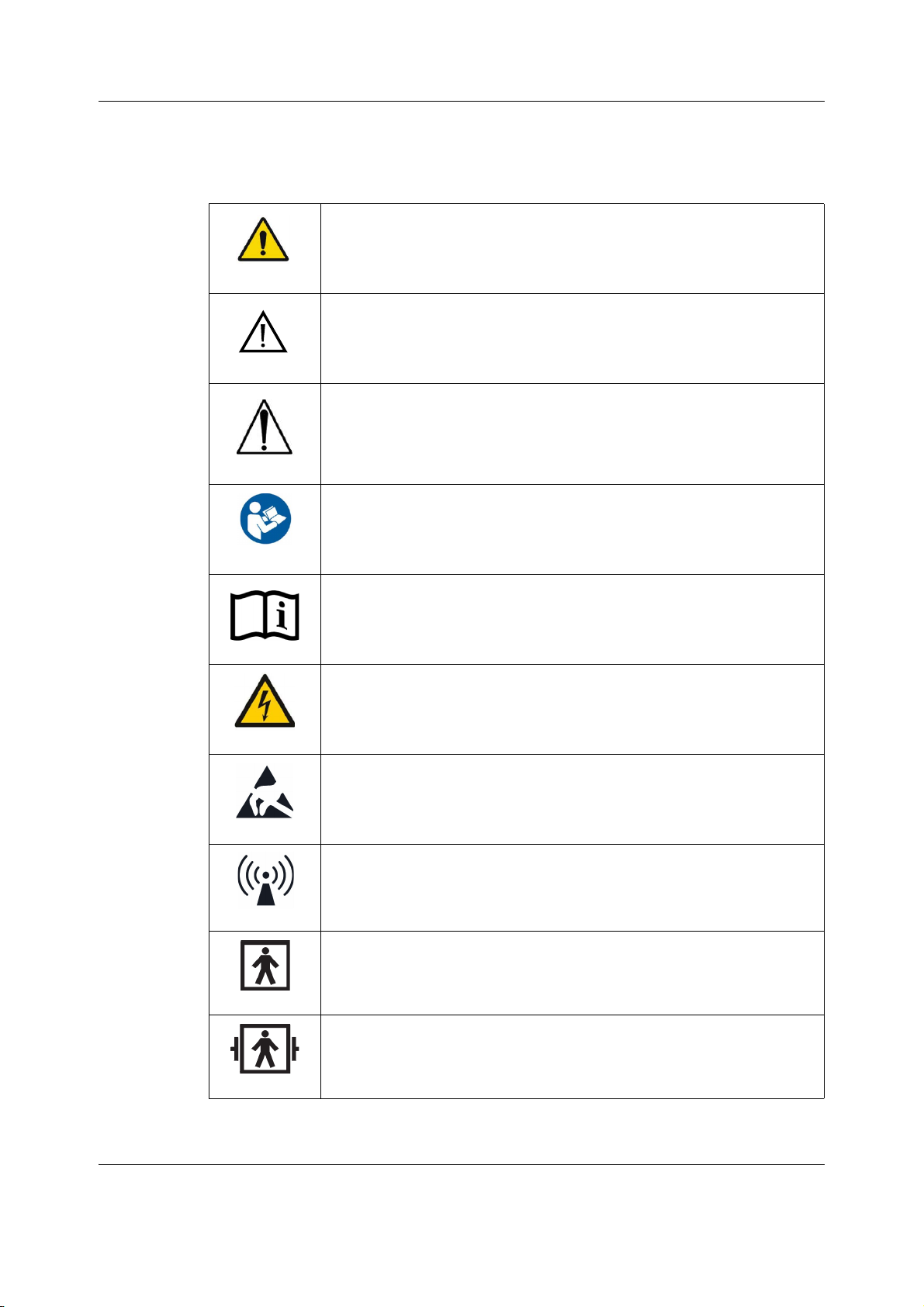
2.3 Safety symbols
NOTE: The following safety-related symbols appear on one or more of the devices.
General warning.
This symbol is identified by a yellow background, black triangular band, and
a black symbol.
General caution sign. IEC 60601-1, 2005 edition
This symbol is identified by a white background, black triangular band, and
a black symbol.
ATTENTION: Consult accompanying documents. IEC 60601-1, 1988 edition.
This symbol is identified by a white background, black triangular band, and
a black exclamation mark.
Follow instructions for use.
This symbol is identified by a blue background and a white symbol.
Consult operating instructions. / Operating instructions.
DANGER - Shock hazard. Dangerous voltage. To reduce the risk of electric
shock, do not remove cover. Refer servicing to qualified service personnel.
This symbol is identified by a yellow background, black triangular band, and
a black symbol.
Electrostatic sensitive device. Connections should not be made to this
device unless ESD precautionary procedures are followed.
Non-ionizing electromagnetic radiation. Interference may occur in the
vicinity of this device.
Type BF (IEC 60601-1) protection against electric shock. Isolated (floating)
applied part suitable for intentional external and internal application to the
patient, excluding direct cardiac application.
Type BF (IEC 60601-1) defibrillator-proof protection against electric shock.
Isolated (floating) applied part suitable for intentional external and internal
application to the patient excluding direct cardiac application.
6
2081903-001
Page 20
Safety information
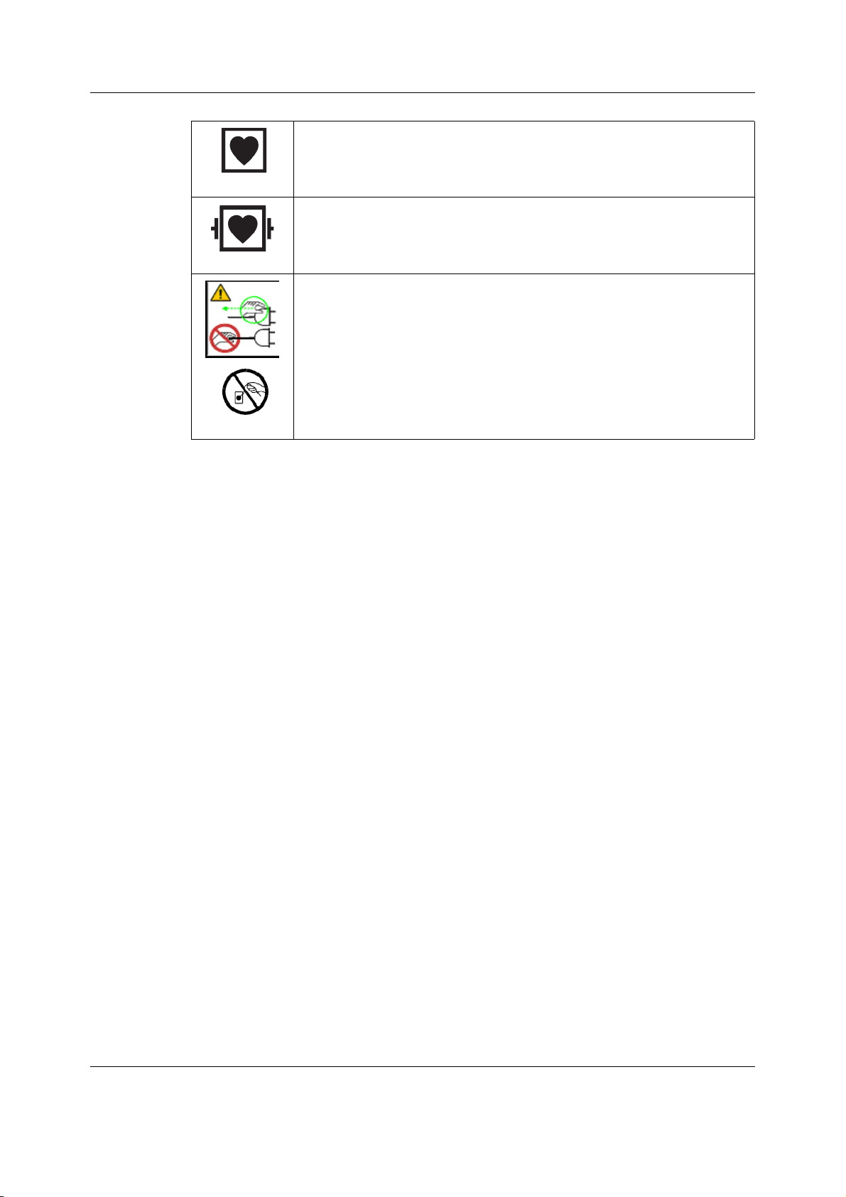
Type CF (IEC 60601-1) protection against electric shock. Isolated (floating)
applied part suitable for intentional external and internal application to the
patient, including direct cardiac application.
Type CF (IEC 60601-1) defibrillator-proof protection against electric shock.
Isolated (floating) applied part suitable for intentional external and internal
application to the patient including direct cardiac application.
Safety ground. Remove power cord from the mains source by grasping the
plug. Do not pull on the cable.
7
2081903-001
Page 21

CARESCAPE Monitor B650
For your notes:
8
2081903-001
Page 22
3 System overview
3.1 System introduction
The CARESCAPE Monitor B650 is a modular monitoring solution for multiple care areas and
intrahospital transport within a professional healthcare facility. The patient monitor offers
various hardware configurations, software options and parameter module support to expand
from basic hemodynamic operations to demanding operating room applications.
The patient monitor is backwards compatible and upgradeable for the future.
3.2 System components
The CARESCAPE Monitor B650 monitoring system components are introduced below.
3.2.1 Monitor
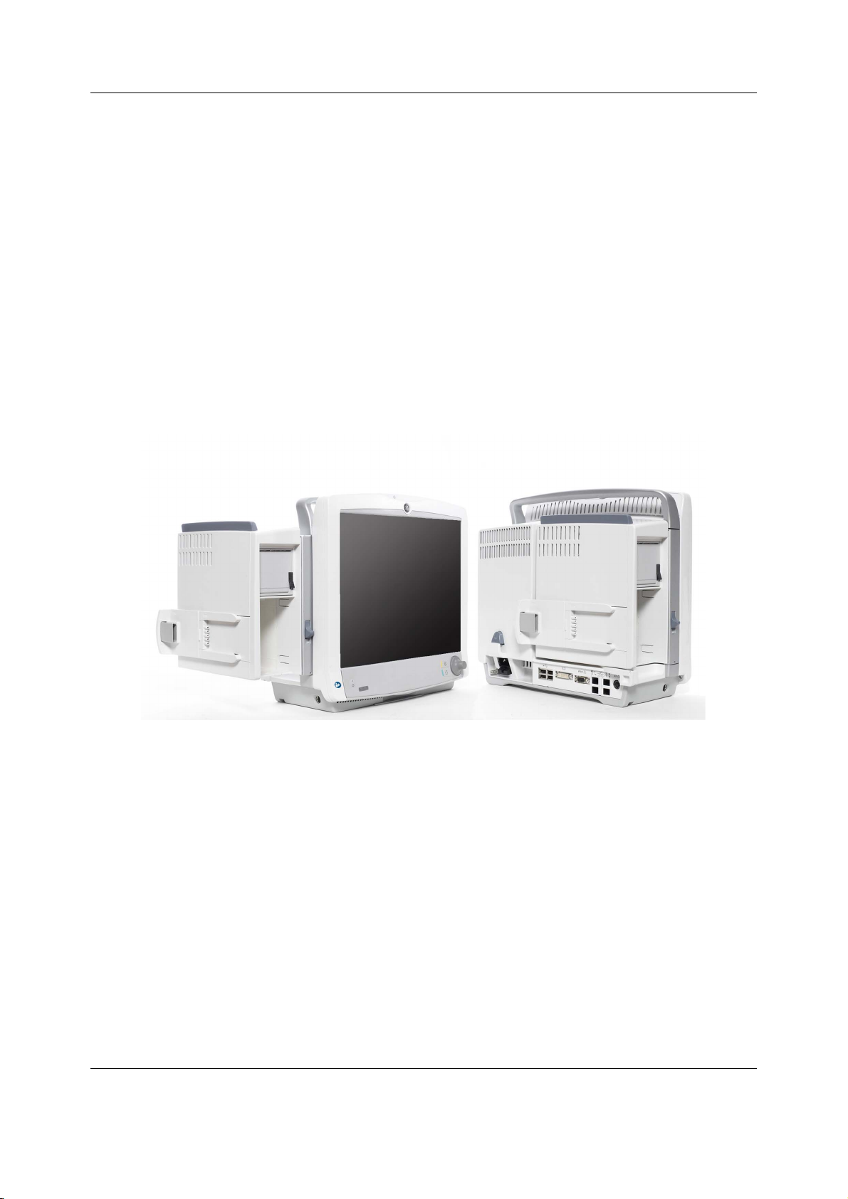
The CARESCAPE Monitor B650 consists of a main unit and a pivoting module frame.
System overview
Main unit
The main unit consists of the following subsystems: power management, CPU, display, user
interface and external interfaces.
The power management subsystem provides the operating voltages for the electronics of the
device and takes care of the battery management. It consists of an AC/DC power supply, a
DC/DC power management board and an optional lithium-ion battery.
The CPU board is the main board of the monitor. It takes care of the user input and acquisition
data processing and displays the processed information on the screen. It controls the monitor
operation and communication with the other subsystems. It also interfaces with
synchronization connector, the optional WLAN card and the speaker. The main software and
all platform and clinical settings are stored in a detachable flash memory.
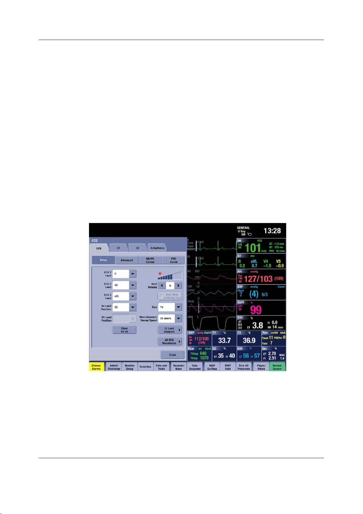
The display subsystem consists of a 15” touchscreen LCD display that has an integrated LED
backlight unit. The display controller is integrated to the CPU board.
The user interface board provides an interface between the CPU board and the keypad, Trim
Knob control, alarm light board and touchscreen sensor.
9
2081903-001
Page 23
CARESCAPE Monitor B650
There are two different configurations of the interface board. They provide connectors for
peripheral devices like USB input devices, network interfaces, a secondary clone display and
other devices.
Module frame
The monitor has a pivoting module frame that includes standard docking for the following
multiparameter hemodynamic modules: Patient Data Module (PDM) and Patient Side Module
(PSM).
The optional E-module support extends the monitoring capabilities to other hemodynamic
modules, gas measurement, brain monitoring and relaxation measurement. The optional
integrated recorder enables local printing to a thermal paper. Both options also are available
as field upgrades.
3.2.2 Software
The patient monitor is highly configurable and provides many monitoring possibilities with a
flexible software licensing model.
The monitor supports care area specific software packages for OR, PACU, ICU, ED and NICU.
Each dedicated software package provides a comprehensive feature set for the different
monitoring needs and can be further extended with the optional feature licenses.
Software license model supports trial licensing and easy field upgrades with license key
activation.
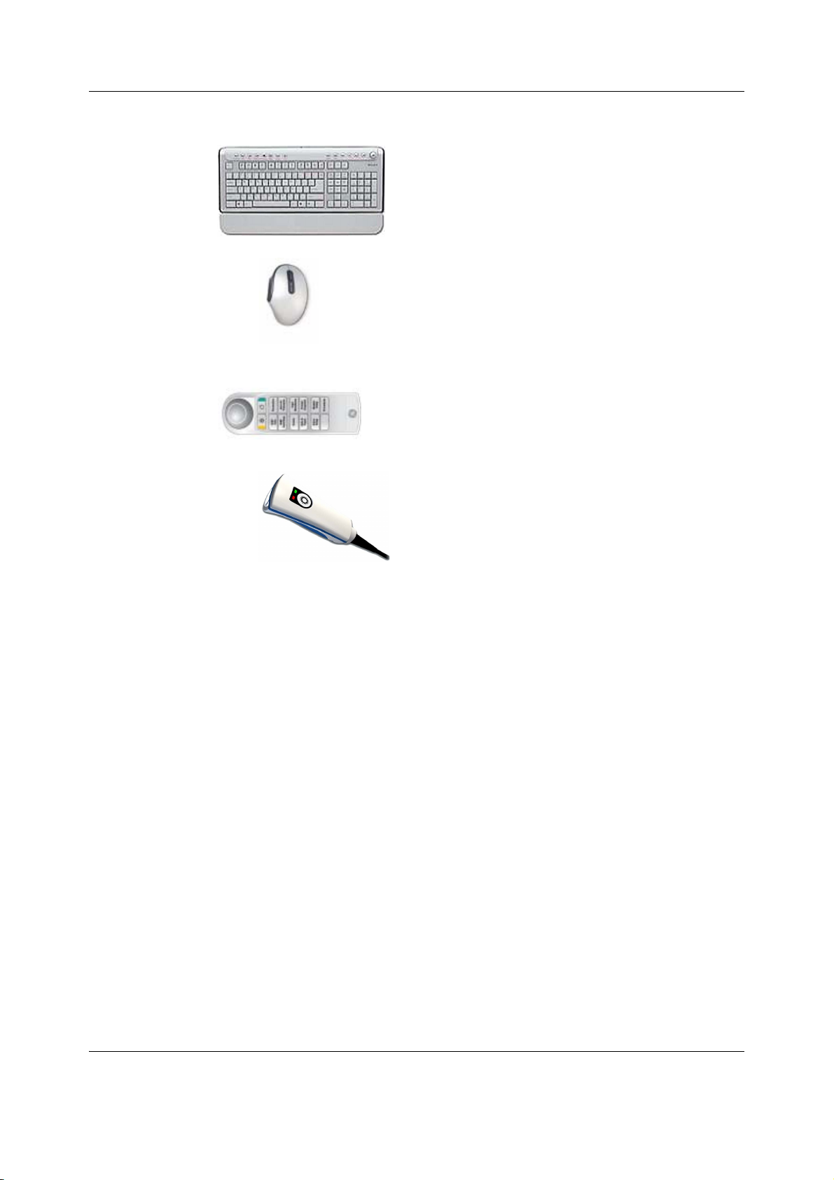
3.2.3 Input devices
You can connect several USB input devices to the patient monitor, including alphanumeric
keyboard, mouse, remote control and barcode reader.
Refer to the patient monitor’s supplemental information manual for a list of compatible USB
input devices.
10
2081903-001
Page 24
System overview
Keyboard
A washable, antibacterial keyboard is specified for
use with the monitor. It may be connected to the
monitor or display via one of the USB connectors.
The keyboard allows you to enter data without
using the touchscreen display.
Mouse
A standard mouse may be connected to the
monitor or display via one of the USB connectors.
The mouse allows you to select any on-screen
items without a Trim Knob control or a touchscreen
display.
Remote control
The remote control provides all patient monitor
controls on a portable component with a Trim Knob
control. The remote control is connected to the
patient monitor via one of the USB connectors.
Barcode reader
The barcode reader can be used to scan a
Technician ID and Patient Information from
barcodes when admitting patients.
11
2081903-001
Page 25
CARESCAPE Monitor B650
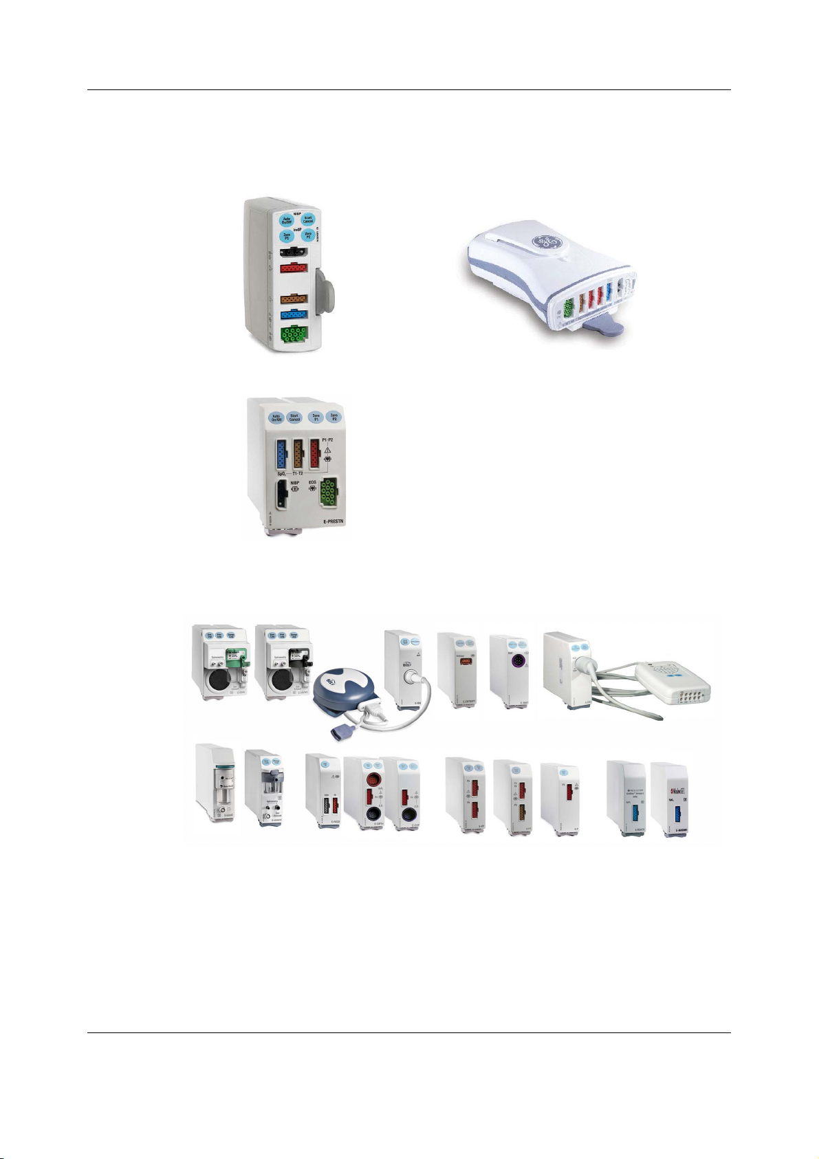
PSM
PDM
E-PRESTN
3.2.4 Acquisition modules
The patient monitor includes standard docking for the following multiparameter hemodynamic
modules: PSM and PDM.
The optional E-module slot can occupy an E-PRESTN module.
The integrated E-module slots can occupy two single-width or one double-width E-modules at
a time.
Refer to the patient monitor’s supplemental information manual for a list of compatible
acquisition devices and to the patient monitor’s user’s manual for a list of parameters each
module measures.
3.2.5 CARESCAPE Network MC or S/5 Network
The patient monitor is compatible both with the CARESCAPE Network MC and the S/5 Network
infrastructures. The optional WLAN support enables wireless network communication using
IEEE 802.11a/b/g.
12
2081903-001
Page 26
System overview
Refer to the patient monitor’s supplemental information manual for a list of compatible
CARESCAPE and S/5 Network devices.
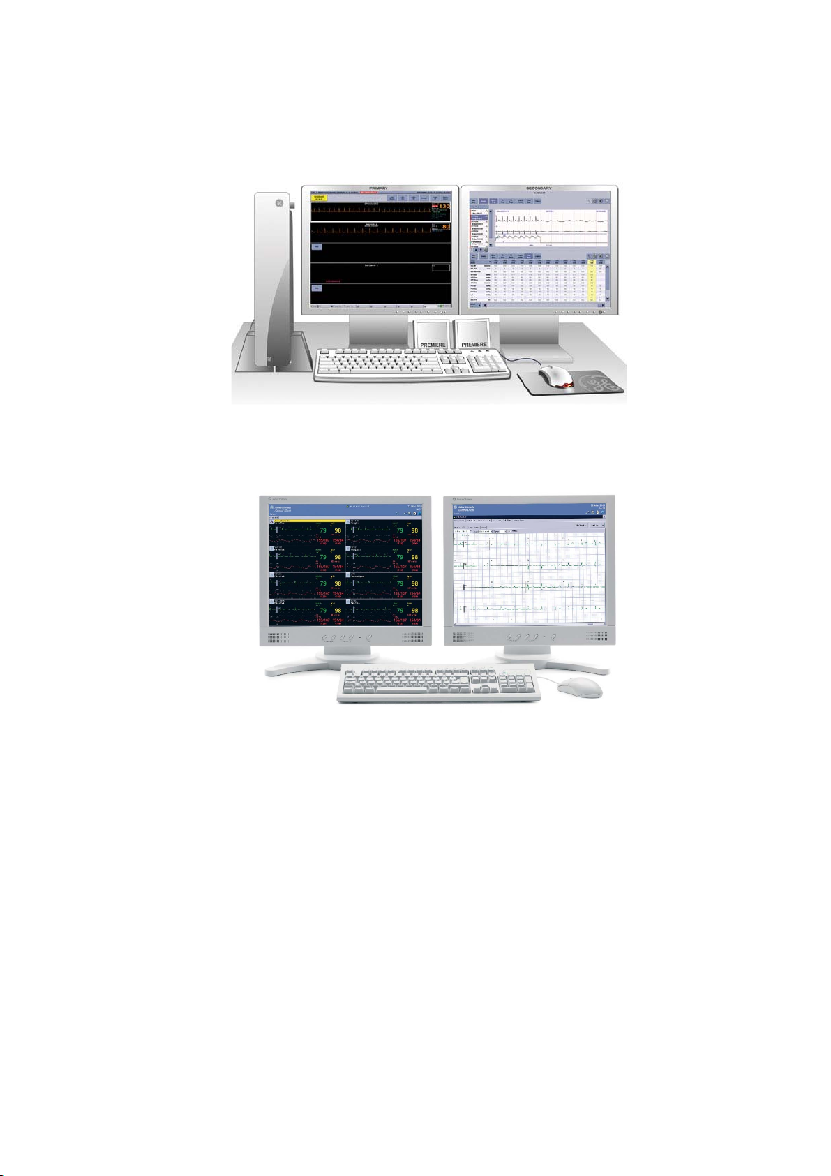
The MC Network establishes communication and allows patient data to be sent to an optional
CIC Pro Clinical Information Center (central station).
The S/5 Network establishes communication and allows patient data to be sent to an iCentral
(central station).
3.2.6 CARESCAPE Network IX
The patient monitor may be connected to the CARESCAPE Network IX.
The IX Network provides you access for example to the MUSE server for MUSE/12SL reports
and to the IX printers. It also enables centralized Webmin access for service personnel from
within the hospital and the InSite with ExC remote service connectivity to GE’s support center.
Refer to the CARESCAPE Network Configuration Guide for details on configuring the
CARESCAPE Network.
13
2081903-001
Page 27
CARESCAPE Monitor B650
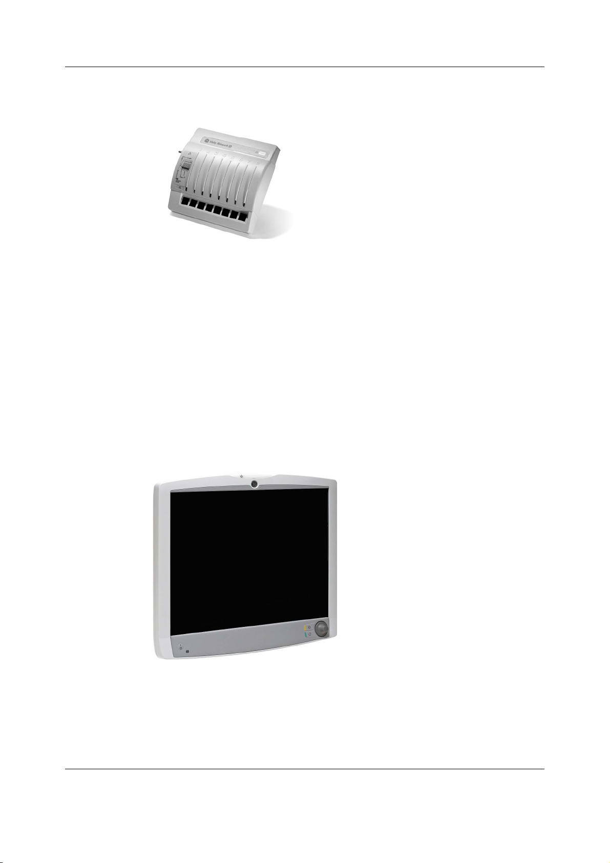
3.2.7 Unity Network ID connectivity device
The Unity Network ID connectivity device acquires digital data from up to eight peripheral
bedside devices (not necessarily manufactured by GE), processes this data and transmits the
formatted data to the patient monitor.
The supported interfaces include anesthesia machines, ventilators, gas analyzers, continuous
cardiac output devices, pulse oximeters, transcutaneous monitors and point-of-care blood gas
monitors.
Refer to the Unity Network Interface Device (ID) Operator's Manual and the patient monitor’s
supplemental information manual for a list of compatible peripheral devices and to the patient
monitor’s user’s manual for the peripheral device parameter data displayed on the patient
monitor.
3.2.8 Secondary display
The patient monitor supports a secondary, clone display that is capable of displaying the same
image as the integrated primary display.
The secondary display is 19” touchscreen LCD with an abbreviated keypad and a Trim Knob
control. The secondary display shows visual alarms and provides connectivity to the USB input
devices.
Refer to the patient monitor’s supplemental information manual for a list of compatible
displays.
14
2081903-001
Page 28
3.2.9 Printers and recorders
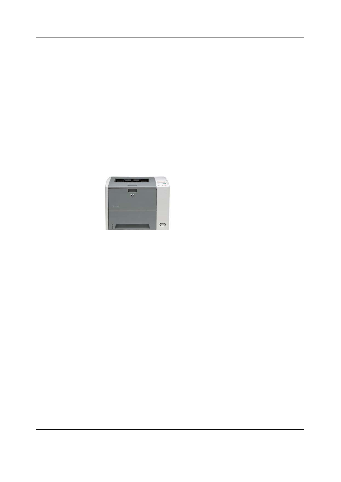
The patient monitor can print to a recorder and to a laser printer.
Refer to the patient monitor’s supplemental information manual for a list of compatible
recorders and laser printers.
Laser printers
A laser printer can print for example waveforms, graphic and numeric trends, snapshots,
events history, parameter specific printouts, stored laboratory data and calculation results and
care reports. Refer to the patient monitor’s user’s manual for more information about printing.
The patient monitor supports printing:
• to a laser printer that is connected to the patient monitor via the IX Network or directly to
the IX connector in the patient monitor.
• to a laser printer that is connected to a CIC Pro Clinical Information Center on the MC
Network.
• to a laser printer that is connected to an iCentral on the S/5 Network.
System overview
Recorders
A recorder may print text, waveforms and numeric trends.
The patient monitor supports printing:
• to an integrated, local recorder (optional).
• to a PRN 50M recorder connected to another patient monitor, or to a CIC Pro Clinical
Information Center, on the MC Network.
15
2081903-001
Page 29
CARESCAPE Monitor B650
3.2.10 Service Interface
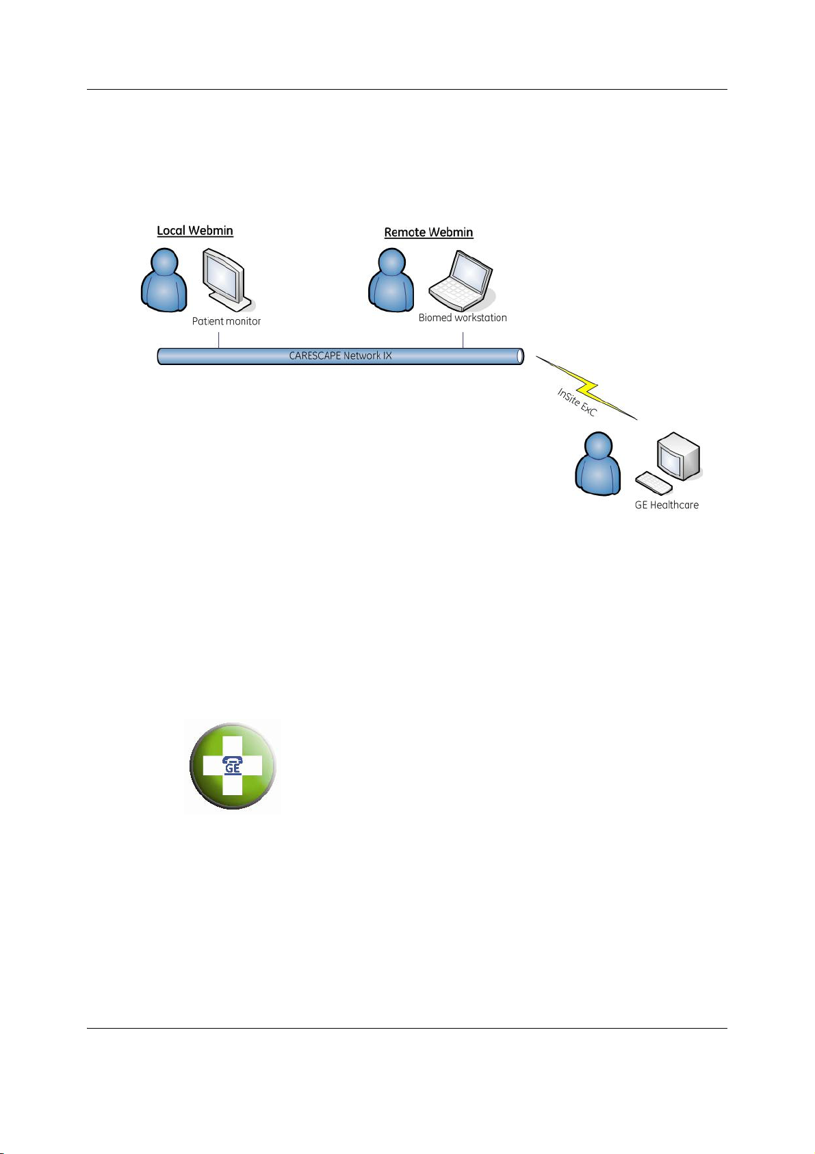
Webmin is a browser-based interface that provides service and diagnostic functions for the
patient monitor. Using a web browser, the user can connect to Webmin to configure, diagnose
and retrieve system information. The user can access Webmin either locally on the patient
monitor or remotely over the IX Network.
Local access to Webmin
The user can access Webmin locally using the integrated browser on the patient monitor.
The other way to access Webmin locally is from a configured service PC that is connected to
the patient monitor with an Ethernet crossover cable.
Remote access to Webmin
The user also can access Webmin remotely using a configured service PC over the IX Network.
InSite with ExC
InSite with ExC provides a set of software applications to manage, diagnose and track systems
at customer sites by using the Internet for secure communications between the customers’
and GE’s firewalls. InSite with ExC consists of Enterprise Server, which resides at GE’s support
center, and Remote Service Agent that resides on a system at the customer site (or on a PC
controlling the system(s) at the customer site).
16
2081903-001
Page 30
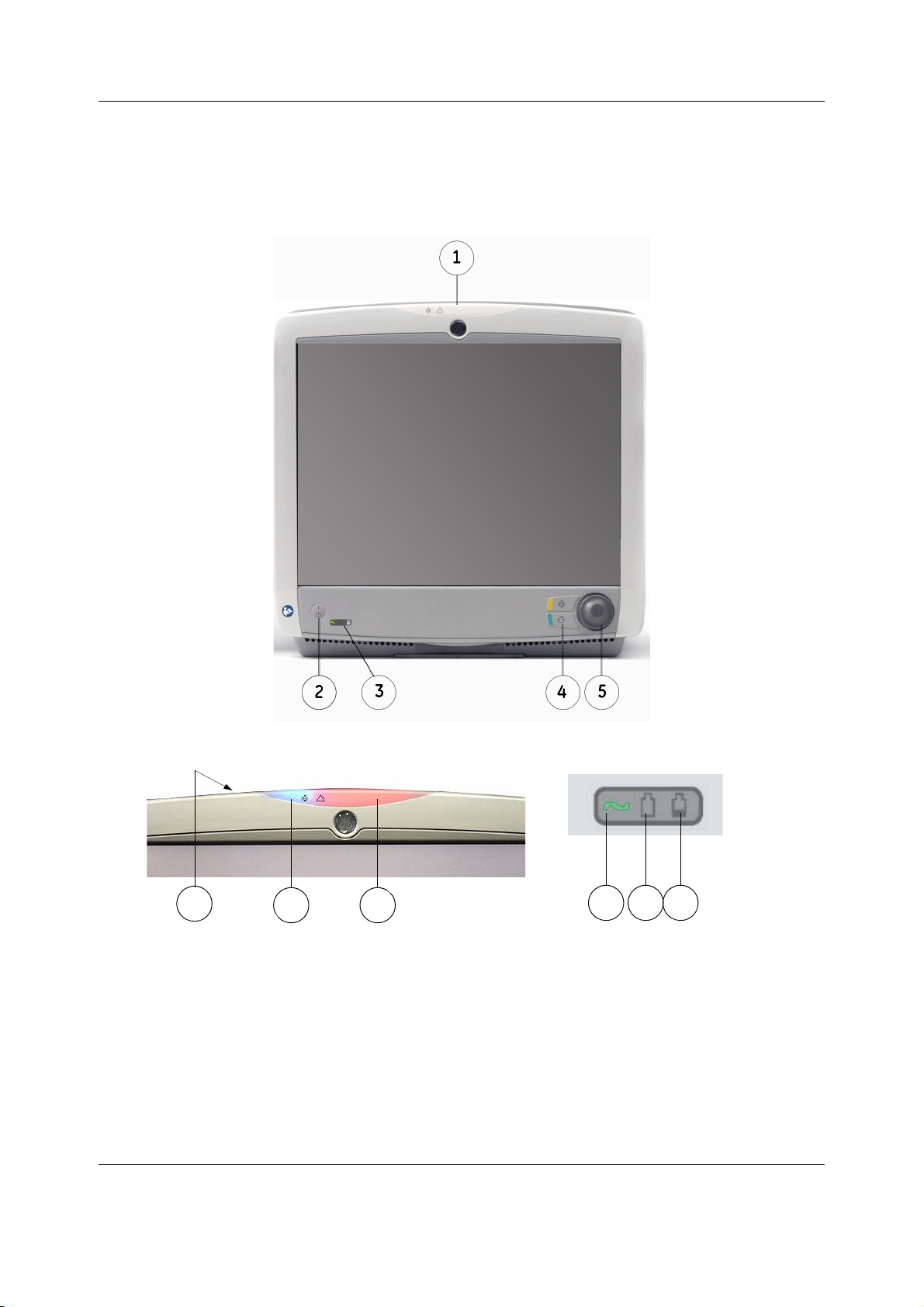
3.3 Controls and connectors
6
7
9 10 11
8
3.3.1 Front view
Display
System overview
B650 with touch screen
Alarm light Power indicators
(1) Alarm light
(2) Power on/standby button
(3) Battery power/ mains power indicators
(4) Abbreviated integrated keypad
(5) Trim Knob control
(6) Ambient light detector lens
(7) Audio alarm paused/off area (blue)
17
2081903-001
Page 31
CARESCAPE Monitor B650
(8) Alarm light area (blue, yellow, or red)
(9) Mains voltage indicator - the green LED is lit when the monitor is connected to AC mains.
(10) Battery use indicator - the green LED is lit when the monitor is operating on battery
power.
(11) Battery charging/failure indicator - the orange LED is lit when the monitor battery is
charging and flashing in case of battery failure or missing battery.
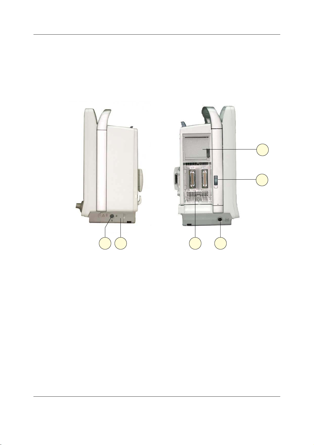
3.3.2 Side views
18
2081903-001
(1) Battery cover lock*
(2) Battery cover*
(3) Module slot* for one double-width or two single-width modules
(4) Defibrillator (ECG) and IABP synchronization (E-modules only)
(5) Release switch for the pivoting module frame
(6) Recorder*
*) optional
NOTE: The Defibrillation synchronization connector can be used only with E-(P)RE(S)TN and
E-PSM(P) modules. PDM module has its own defibrillation synchronization connector.
Page 32
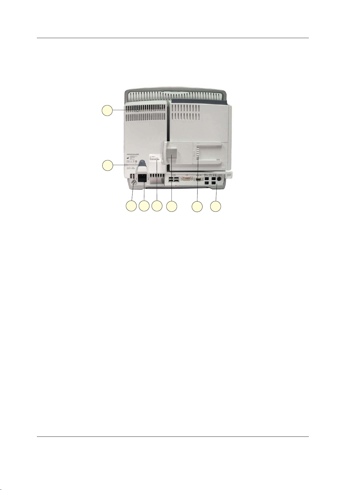
3.3.3 Rear views
System overview
(1) Power LEDs for troubleshooting
(2) Cable clamp for power cord
(3) Equipotential connector
(4) Receptacle for power cord and fuse holder
(5) Device label
(6) Slide mount with connector for PDM
(7) Slide mount with connector for PSM
(8) Advanced Interface Board or Standard Interface Board
19
2081903-001
Page 33
CARESCAPE Monitor B650
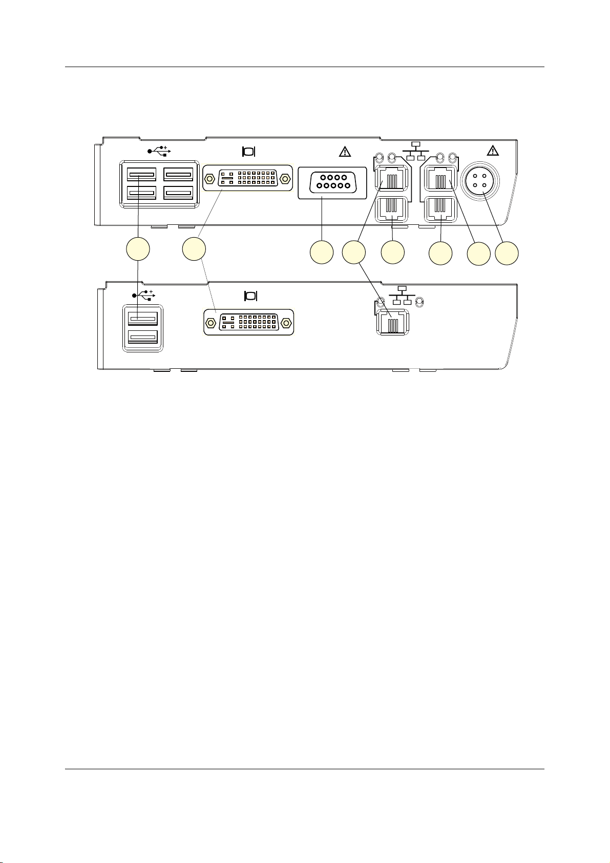
Advanced Interface Board
Standard Interface Board
Interface board connectors
0&
H3RUW
(1) USB ports (2 or 4 pcs USB 2.0 Type A connectors)
(2) DVI-I connector for a secondary display
(3) ePort connector for PDM module
(4) Network connector for the MC Network & S/5 Network
(5) Network connector for the Unity Network Interface Device (ID) connectivity device
(6) Not in use
(7) Network connector for the IX Network
(8) Remote-on connector
,'
0&
1$
,;
;
3.4 Service information
3.4.1 Service requirements
Follow the service requirements listed below.
• Refer equipment servicing to GE authorized service personnel only.
• Any unauthorized attempt to repair equipment under warranty voids that warranty.
• It is the user's responsibility to report the need for service to GE or to one of their
authorized agents.
• Failure on the part of the responsible individual, hospital, or institution using this
equipment to implement a satisfactory maintenance schedule may cause undue
equipment failure and possible health hazards.
• Regular maintenance, irrespective of usage, is essential to ensure that the equipment will
always be functional when required.
20
2081903-001
Page 34
System overview
CAUTION DISPOSAL - At the end of its service life, the product described in this manual,
as well as its accessories, must be disposed of in compliance with the
guidelines regulating the disposal of each product. If you have any questions
concerning disposal of a product, please contact GE or its representatives.
3.4.2 Equipment identification
Unique Device Identifier (UDI)
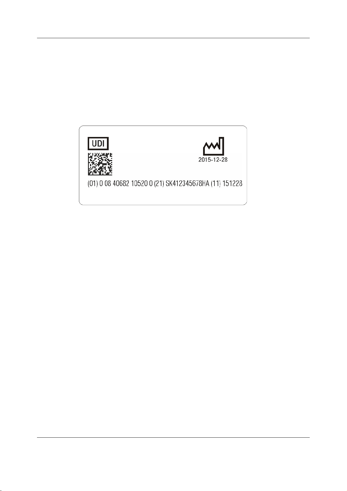
Every medical device has a unique marking for identification. The UDI marking appears on the
device labeling The characters used in the UDI marking represent specific identifiers.
In the example above:
Device identifier:
• (01) = GS1 global trade item number (GTIN) of the device.
• 1234567891234 = Global trade item number.
Production identifiers:
• (21) = GS1 application identifier for the serial number of the device.
• SK412345678HA = Serial number, where the first three characters represent Product
Code.
• (11) = GS1 application identifier for the manufacturing date of the device.
• 151228 = Manufacturing date: year-month-day (YYMMDD).
Note that for some product types the production identifier can have other elements instead of
the ones listed above:
• (10) = GS1 application identifier for the batch or lot number, followed by the batch or lot
number.
• (17) = GS1 application identifier for the expiration date of the device, followed by the
expiration date.
Device label
Every GE device has a unique serial number for identification. The serial number is written in a
device label. A sample of the information on a device label is shown below. The product code
for CARESCAPE Monitor B650-02 is SK4.
21
2081903-001
Page 35

CARESCAPE Monitor B650
3.5 Product security
The patient monitoring software incorporates an assortment of security features designed to
allow a flexible approach to safe and secure implementation, focusing on the principles of
confidentiality, integrity, and availability. These features assist you in using the system in a
manner that protects patient privacy and security in your setting, and also addresses
expectations for the environment where the system will be used.
3.5.1 Security features
Access control
Access control is the overall mechanism used to determine and enforce the following:
• Who has access
• How individuals gain access
• When access is permitted
• What information may be accessed
Other than clinical and Webmin applications, access to other subsystems (for example BIOS) is
restricted. The clinical and Webmin application interfaces have a role-based access control (for
example, biomed and clinical). A user may log into these interfaces (for example, Webmin) to
perform operations that are limited to the generic user. See the user and technical manuals for
detailed information on available features.
22
2081903-001
Authentication
Authentication is the process of proving individual identity, and is a key element in an access
control system. In the clinical and Webmin applications, there are certain features that require
user authentication. To access these features, the user must log into the clinical and Webmin
applications with a valid username and password.
Authorization
Authorization is the process of granting and revoking access to information, and is another key
element in an access control system. Although primarily an administrative process that is
driven by an organization’s policies and procedures, the patient monitor contains features that
will help implement and enforce an organization’s method.
Both clinical and Webmin applications have an authorization mechanism to provide
information to the user.
Audit
The ability to record and examine system activity is crucial to a successful information security
program, as well as a regulatory requirement in most environments. The patient monitor stores
system and Webmin access logs.
Page 36

System overview
Malicious software protection
Vigilant defense on many levels is required to keep systems free from compromise by
malicious software. Effective protection requires cooperation and partnership between GE and
our customers.
Based on the Linux Operating System, the patient monitor has a built-in firewall to allow
external communication to occur on a limited number of ports on the IX Network.
The following product features contribute to defense against malicious software:
• System integrity checking
The patient monitor performs integrity checking on the root file system to detect any
changes to the file system contents. Any modification to the root file system contents will
generate an error to the patient monitoring software application. The patient monitoring
software will then display a technical alarm to the user.
• Device design and configuration (hardening)
The patient monitor has been hardened through the restriction and removal of user
access to core operating system functionality. In addition, unneeded functionality has
been removed or restricted.
• Antivirus software
To provide seamless real-time patient monitoring, the patient monitor does not have
antivirus software.
• Security updates and patching processes
Security updates and patches cannot be applied to the CARESCAPE product without
going through GE’s vigorous software verification and validation process. Any software
update needs will be communicated by GE.
3.5.2 Security operations
Network security
GE requires that the MC port of the patient monitor be connected to a physically or virtually
dedicated CARESCAPE Network MC or S/5 Network, isolated from all other networks.
GE requires that the IX port of the patient monitor be connected to a physically or virtually
dedicated CARESCAPE Network IX with controlled connection to the organization’s general
purpose computing network. Traffic between the organization’s network and IX port of the
patient monitor must be limited to the following packet flows listed below.
Inbound
Source device Destination device Protocol Destination port Use
Any
Customer
defined
Customer
defined
DHCP server tcp 67, 68 DHCP
Packets that are part of the communication initiated by authorized devices in the
organization’s network are allowed to go out of the IX Network (reflexive).
Patient monitor
icmp N/A ping
tcp 10000 Webmin
tcp 10001 Software
transfer
23
2081903-001
Page 37

CARESCAPE Monitor B650
Outbound
Source device Destination Device Protocol Destination port Use
Patient
monitor
Any icmp N/A ping
us1-ws.service.gehealthcare.
com
us1-rd.service.gehealthcare.
com
Printer tcp 631 Printing
MUSE tcp 80 MUSE
Packets that are part of the communication initiated by the patient monitor are allowed into
the IX Network (reflexive).
tcp 443 InSite with ExC
(Web Services)
tcp 443 InSite with ExC
(Remote Tunnel)
Wireless Network Security
The patient monitor can operate both in the wired and the wireless MC Network or S/5
Network. IX Network is wired only.
Refer to the Wireless LAN Network Installation Guide and S/5 Network Installation Guide for
more information regarding the security features of the wireless MC Network and the S/5
Wireless Network, respectively.
Network Identification
The Service Set Identifier (SSID), also known as network name, identifies a particular wireless
network. The patient monitors shall be configured to use the same SSID with the access points
to enable wireless communication. It is recommended to configure access points not to
broadcast SSID to the wireless network.
The wireless MC Network shall be logically separated to its own virtual LAN with a dedicated
SSID. The S/5 Wireless Network shall have dedicated access points that are physically isolated
from all other networks.
Security (Authentication and Confidentiality)
The data transmitted on the wireless network can be secured by one of the following methods:
− WEP (64-bit) (NOTE: S/5 only)
− WEP (128-bit)
− WPA-PSK (TKIP) (NOTE: MC only)
− WPA2-PSK (AES-CCMP) (NOTE: MC Only)
3.5.3 Product change management
GE has rigorous software verification and validation processes. Any software update needs will
be communicated by GE. The patient monitoring system, including all aspects of software,
should be used as it was intended by GE.
3.5.4 Communication
For detailed product security information, go to one of the following Web addresses:
24
2081903-001
Page 38
http://www.gehealthcare.com/usen/security
http://www.gehealthcare.com/usen/security/mds2.html
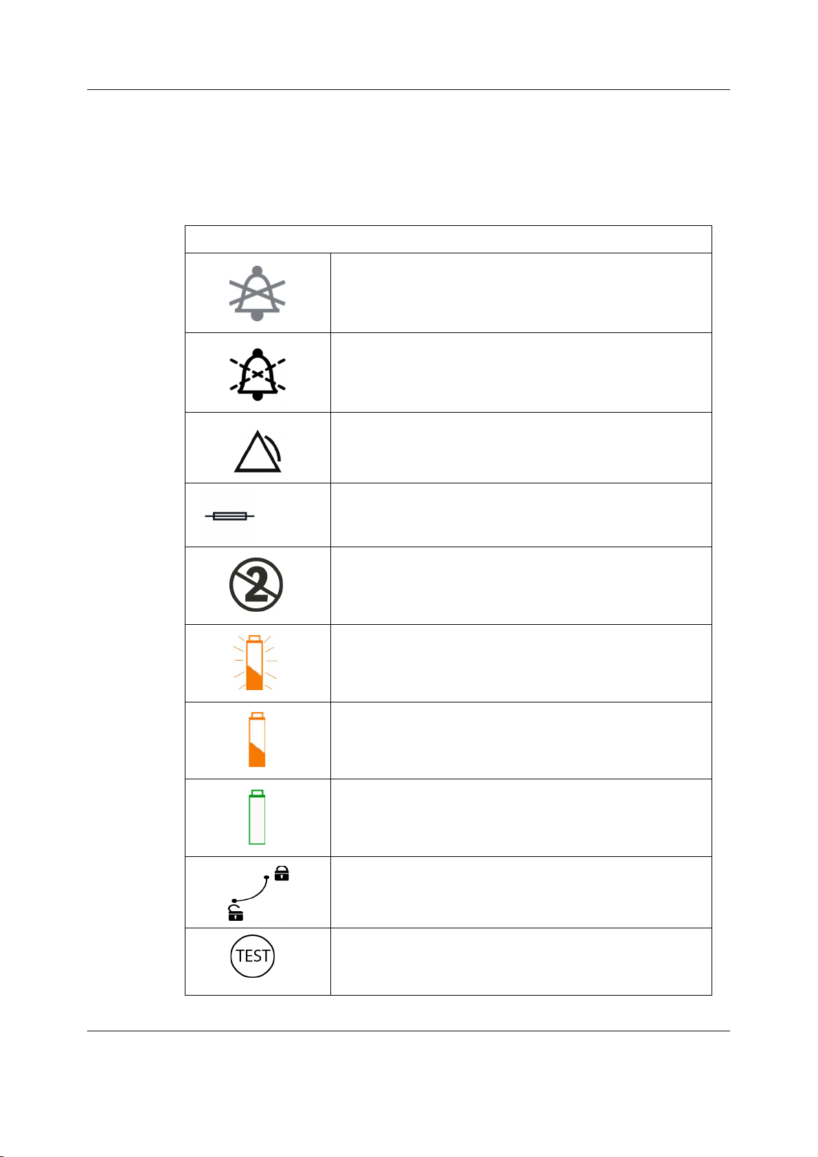
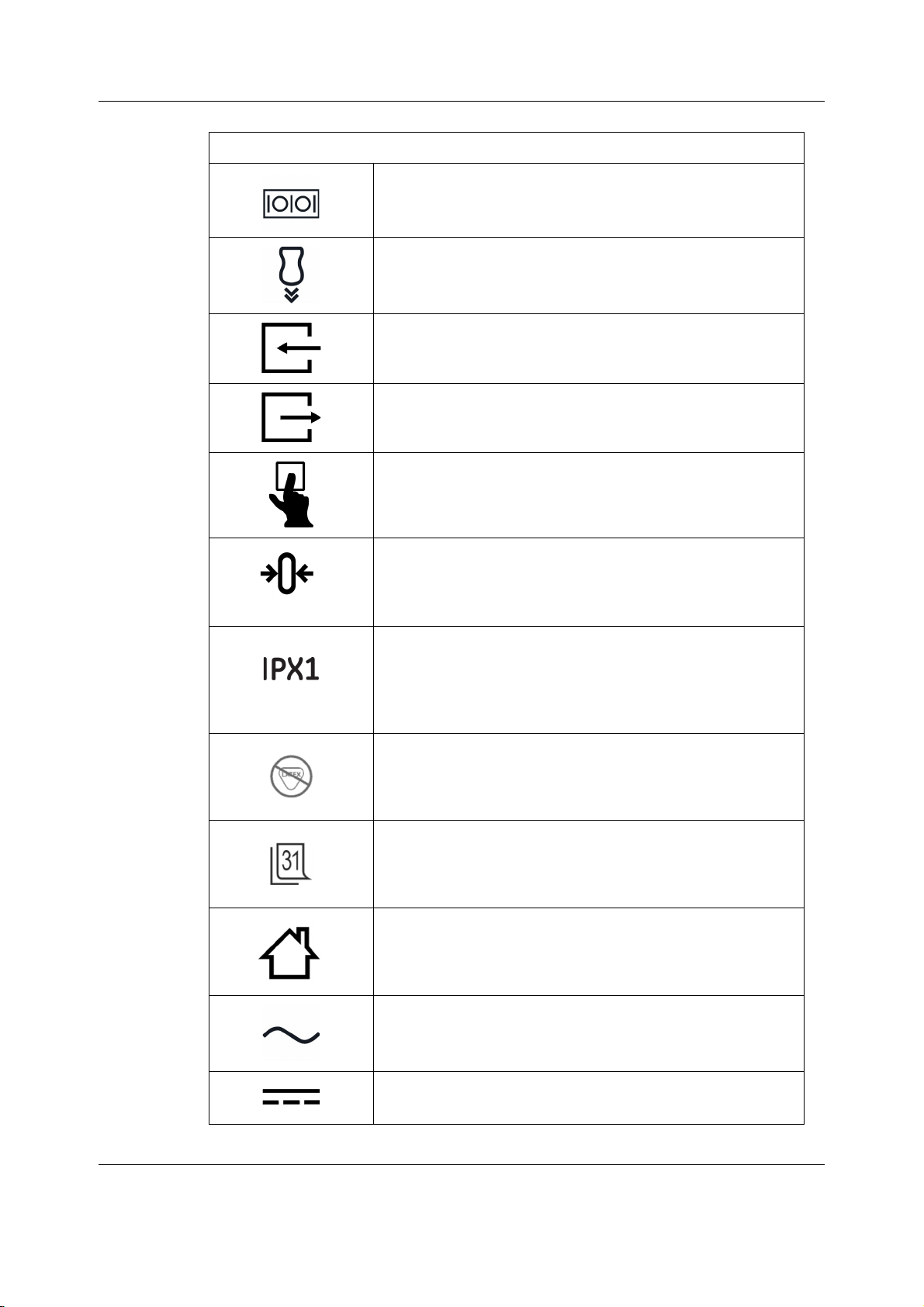
3.6 Equipment symbols
The following symbols appear on one or more of the devices.
Bell cancel. Audio off.
Audio pause. Temporary audio off.
General alarm.
System overview
Fuse. Replace with identical type and rating fuse.
Do not reuse.
Battery (monitor): The flashing orange symbol indicates that
there is a battery failure/missing battery.
Battery (monitor): The solid orange symbol indicates that the
battery is being charged.
Battery (monitor). The solid green symbol indicates that the
monitor is being used on battery power.
Battery (monitor): The battery slot cover is open/closed.
Battery (monitor): Test button on the battery to check the battery
charge level.
2081903-001
25
Page 39
CARESCAPE Monitor B650
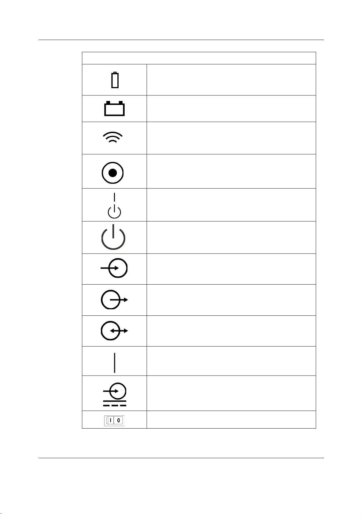
The following symbols appear on one or more of the devices.
Battery (monitor). Located on the battery slot cover.
Battery (PDM).
Communication. (PDM)
Power indicator. (PDM)
On/standby button.
Standby or power indicator.
Signal/power input.
Signal/power output.
Signal/power input/output (combined).
ON. Power connection to the mains.
Power supply connector.
26
2081903-001
Power switch.
Page 40
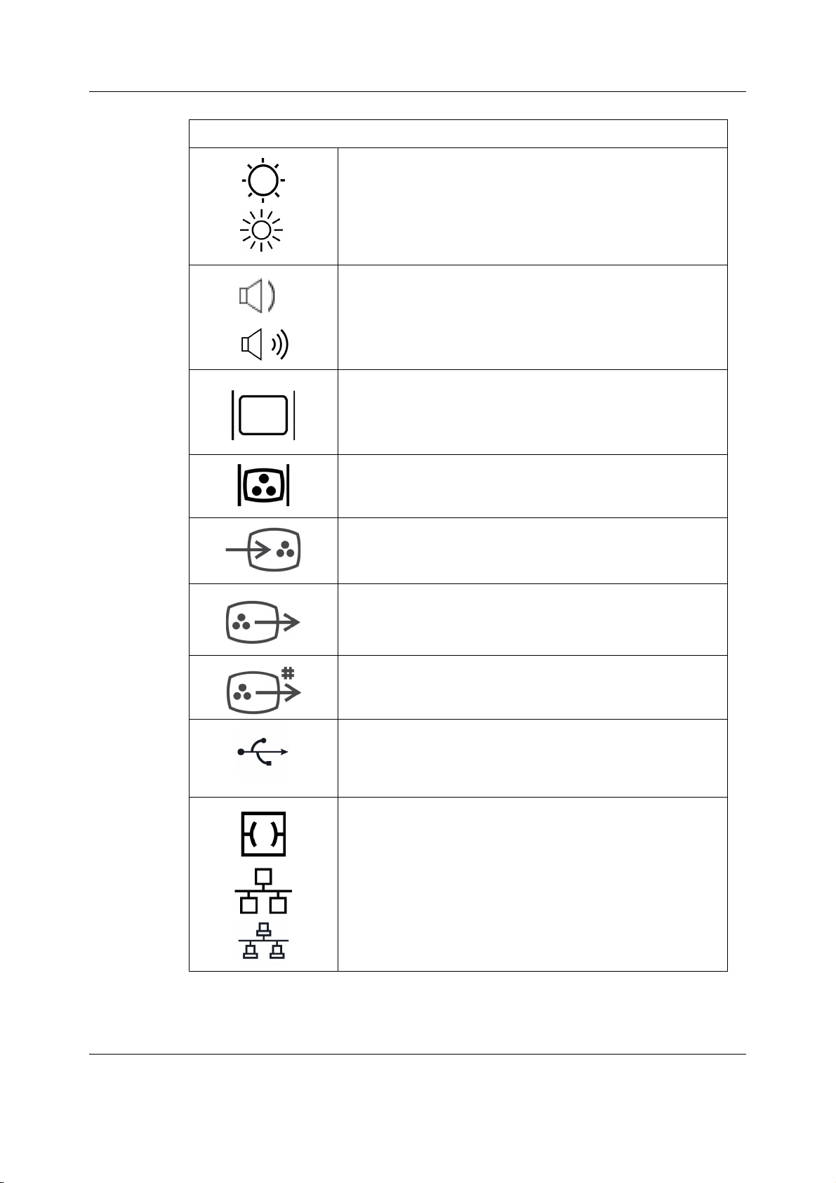
The following symbols appear on one or more of the devices.
Display brightness controls.
Display speaker volume controls.
DVI connector. Video output connector for digital or analog
source.
System overview
Color display connector port.
Color video input. Video input connector for digital or analog source.
Color video output, digital. Video output for analog source.
Color video output. Video output for digital source.
USB connector.
Ethernet connectors
27
2081903-001
Page 41
CARESCAPE Monitor B650
The following symbols appear on one or more of the devices.
Serial interface.
Tram-Net and ePort connector for PDM module, E-module frame,
Tram-Rac housing, and TRAM modules
.
Gas inlet.
Gas outlet.
Press to open.
Zero all. (PDM)
Degree of ingress protection.
Degree of protection against harmful ingress of water:
Components not marked with an IPXn code are rated as
Ordinary (no protection against fluid ingress). All other IPXn rated
components have the degree of protection per the ‘n’ rating.
Latex free.
D-lite/Pedi-lte: Add date.
Home. Return to the main display.
Alternating current.
Green symbol on the B650 and B450 monitor front panel: the
monitor is being used on mains power.
28
2081903-001
Direct current.
Page 42
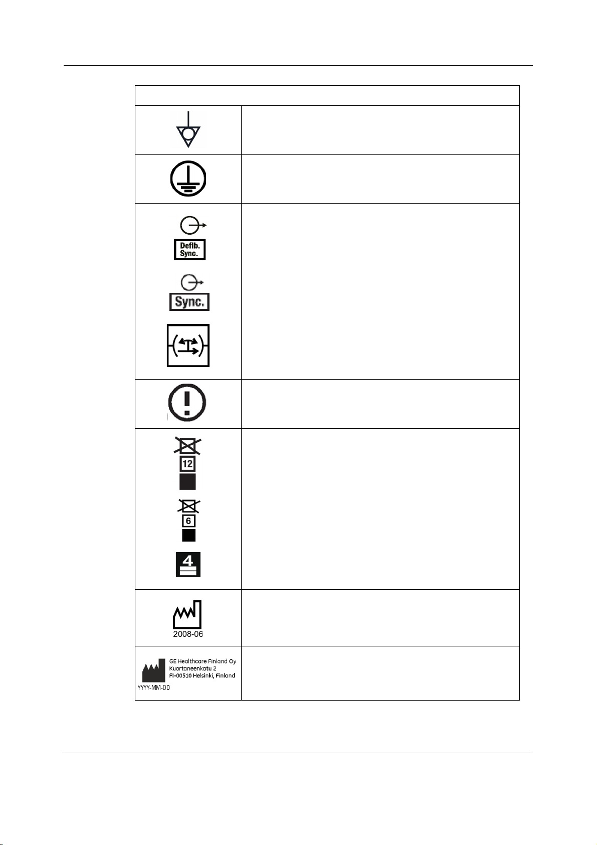
The following symbols appear on one or more of the devices.
Equipotentiality. Connect device to a potential equalization
conductor.
Protective earth ground. Connectors grounded to the AC power
source.
Defibrillator synchronization connectors.
System overview
(WLAN) Class 2 Identifier
Stacking limit by number.
Date of manufacture. This symbol indicates the date of
manufacture of this device. The first four digits identify the year
and the last two digits identify the month.
Manufacturer address and date of manufacture. The first four
digits identify the year, the following two digits identify the
month, and the last two digits identify the day.
29
2081903-001
Page 43
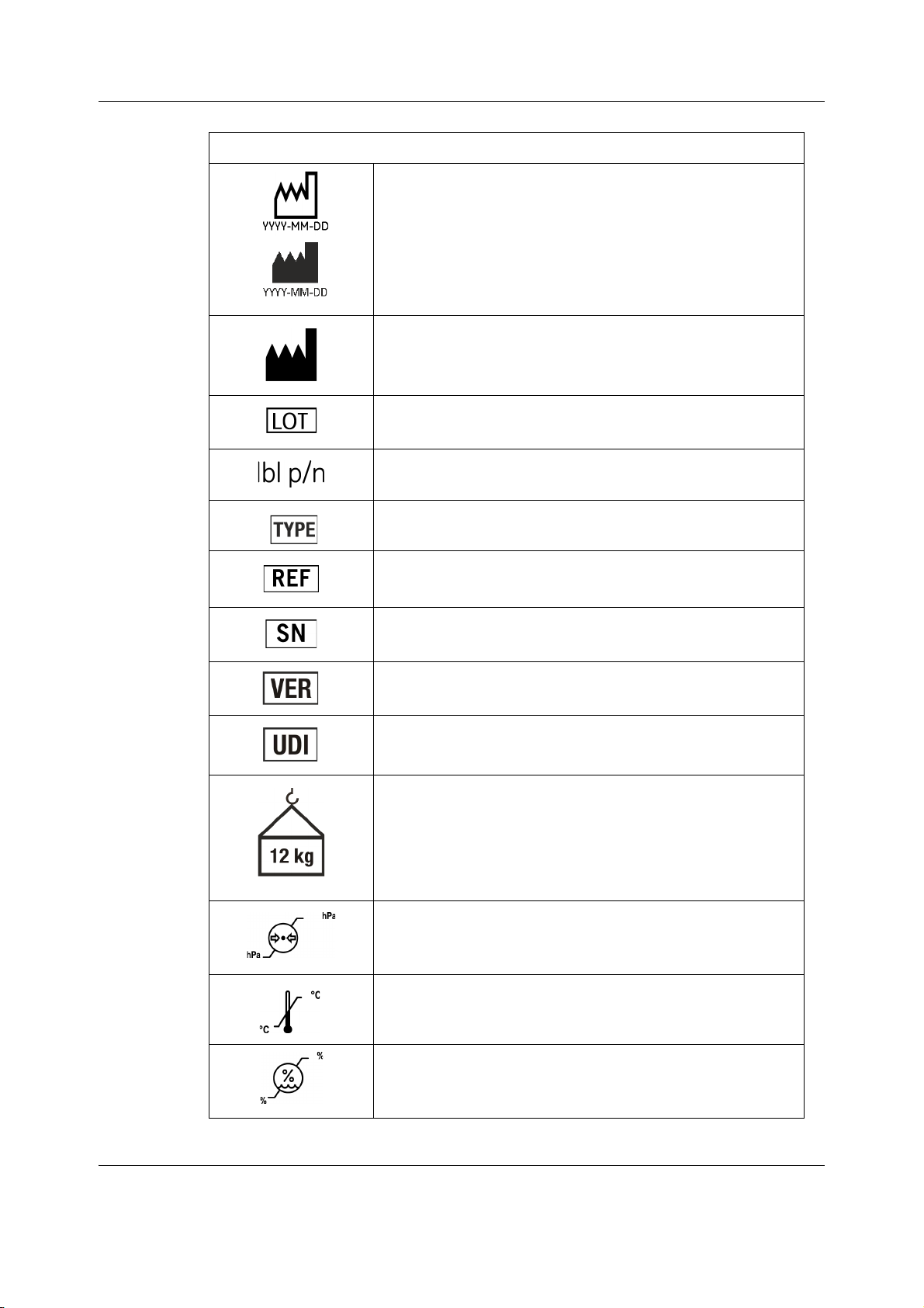
CARESCAPE Monitor B650
The following symbols appear on one or more of the devices.
Date of manufacture. This symbol indicates the date of
manufacture of this device. The first four digits identify the year,
the following two digits identify the month, and, if indicated, the
last two digits identify the day.
Manufacturer name and address.
Batch or lot number.
Abbreviation for label part number.
Identifies the device type.
Catalogue or orderable part number.
Device serial number.
Device hardware version.
Every device has a unique marking for identification. The UDI
marking appears on the device label.
Mass of typical portable RGM (respiratory gas monitor)
configuration.
The indicated mass (12 kg in this example) varies per RGM
configuration.
Atmospheric pressure limitations.
Temperature limitations.
30
2081903-001
Humidity limitations.
Page 44
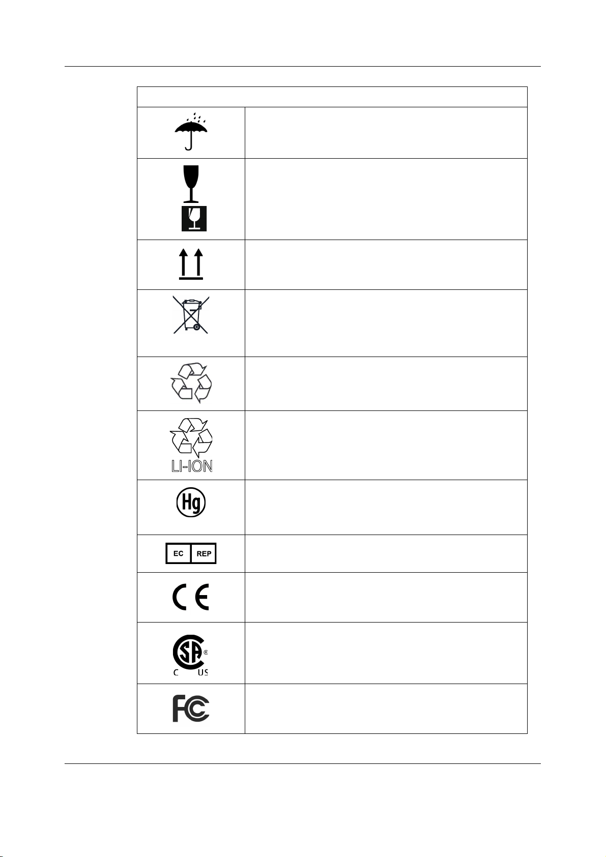
The following symbols appear on one or more of the devices.
Keep dry. Protect from rain.
Fragile. Handle with care.
This way up.
This symbol indicates that the waste of electrical and electronic
equipment must not be disposed as unsorted municipal waste
and must be collected separately. Please contact an authorized
representative of the manufacturer for information concerning
the decommissioning of your equipment.
System overview
Recycled materials or may be recycled.
Recyclable Lithium-ion.
Mercury. This product consists of devices that may contain
mercury, which must be recycled or disposed of in accordance
with local, state, or country laws. (Within this system, the
backlight lamps in the patient monitor display contain mercury.)
European authorized representative.
European Union Declaration of Conformity.
Indicates that the product is certified for both the U.S. and
Canadian markets, to the applicable U.S. and Canadian
standards.
FCC. USA only. Complies with applicable US government (Federal
Communications Commission) radio-frequency interference
regulations.
2081903-001
31
Page 45
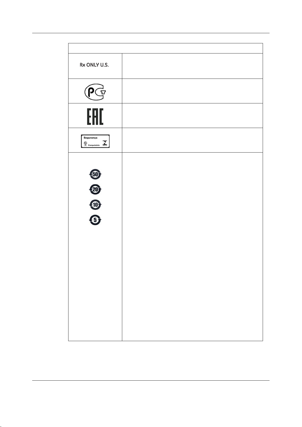
CARESCAPE Monitor B650
The following symbols appear on one or more of the devices.
CAUTION U.S. federal law restricts this device to
sale by or on the order of a physician.
Russia only. GOST-R mark.
Eurasian Economic Union countries only. Eurasian Conformity
mark. Conformity to applicable technical regulations of Customs
Union.
Brazil only. INMETRO certificate.
NOTE: The following symbols (required by China law only) are
representative of what you may see on your equipment.
The number in the symbol indicates the EFUP period in years, as
explained below. Check the symbol on your equipment for its
EFUP period.
This symbol indicates the product contains hazardous materials
in excess of the limits established by the Chinese standard
SJ/T11363-2006 Requirements for Concentration Limits for
Certain Hazardous Substances in Electronic Information
Products. The number in the symbol is the Environment-friendly
User Period (EFUP), which indicates the period during which the
toxic or hazardous substances or elements contained in
electronic information products will not leak or mutate under
normal operating conditions so that the use of such electronic
information products will not result in any severe environmental
pollution, any bodily injury or damage to any assets. The unit of
the period is “Year”.
In order to maintain the declared EFUP, the product shall be
operated normally according to the instructions and
environmental conditions as defined in the product manual, and
periodic maintenance schedules specified in Product
Maintenance Procedures shall be followed strictly.
Consumables or certain parts may have their own label with an
EFUP value less than the product. Periodic replacement of those
consumables or parts to maintain the declared EFUP shall be
done in accordance with the Product Maintenance Procedures.
This product must not be disposed of as unsorted municipal
waste, and must be collected separately and handled properly
after decommissioning.
32
2081903-001
Page 46
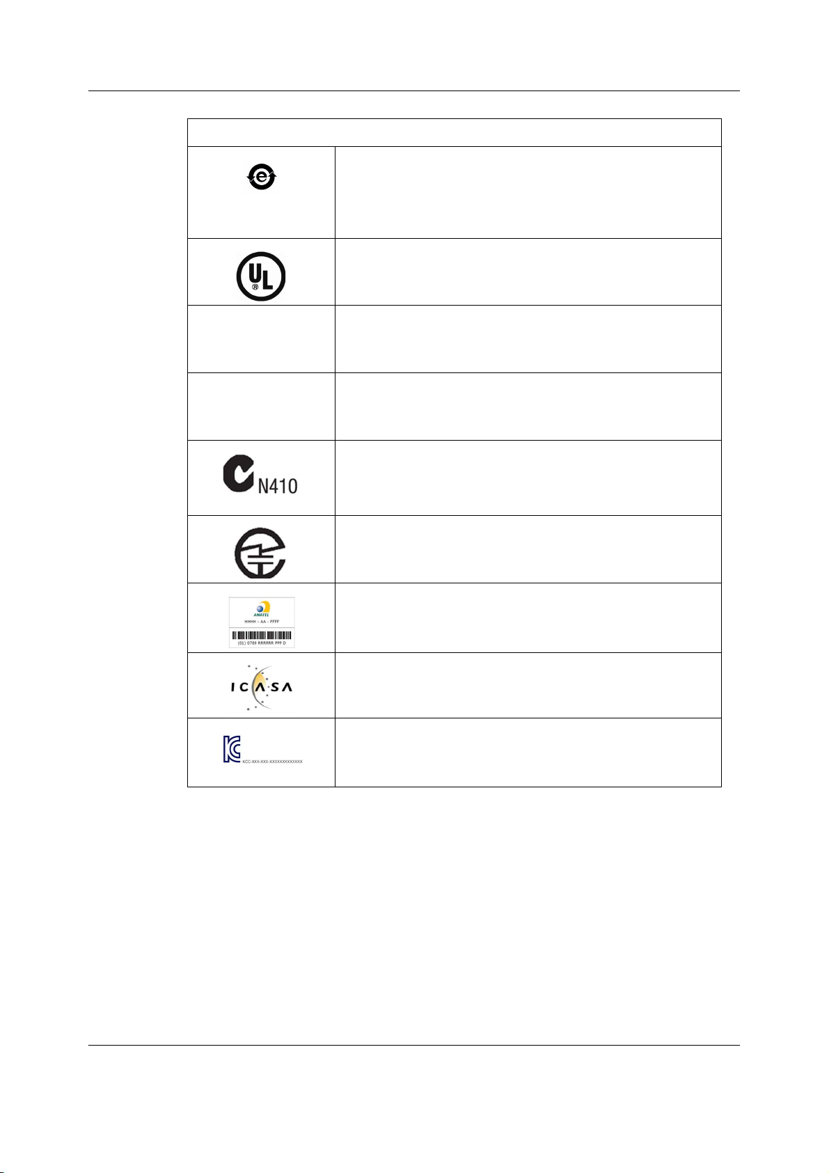
The following symbols appear on one or more of the devices.
IC
CMIIT ID
This symbol indicates that this electronic information product
does not contain any toxic or hazardous substance or elements
above the maximum concentration value established by the
Chinese standard SJ/T11363-2006, and can be recycled after
being discarded, and should not be casually discarded.
Underwriters Laboratories product certification mark.
Canada only. Industry Canada certification number indicates
that this product meets the applicable Industry Canada technical
specifications.
China only. China Ministry of Industry and Information
Technology identification number for Radio Transmission
Equipment Type Approval.
Australia only. The product complies with the applicable
Australian standard and establishes a traceable link between the
equipment and the manufacturer, importer or their agent
responsible for compliance.
System overview
Japan only. Approved under Japan TELEC requirements.
Brazil only. Approved under ANATEL (Agência Nacional de
Telecomunicações) requirements.
South Africa only. Approved under ICASA (Independent
Communications Authority of South Africa) requirements.
Korea only. Approved under KCC (Korea Communications
Commission) requirements.
33
2081903-001
Page 47
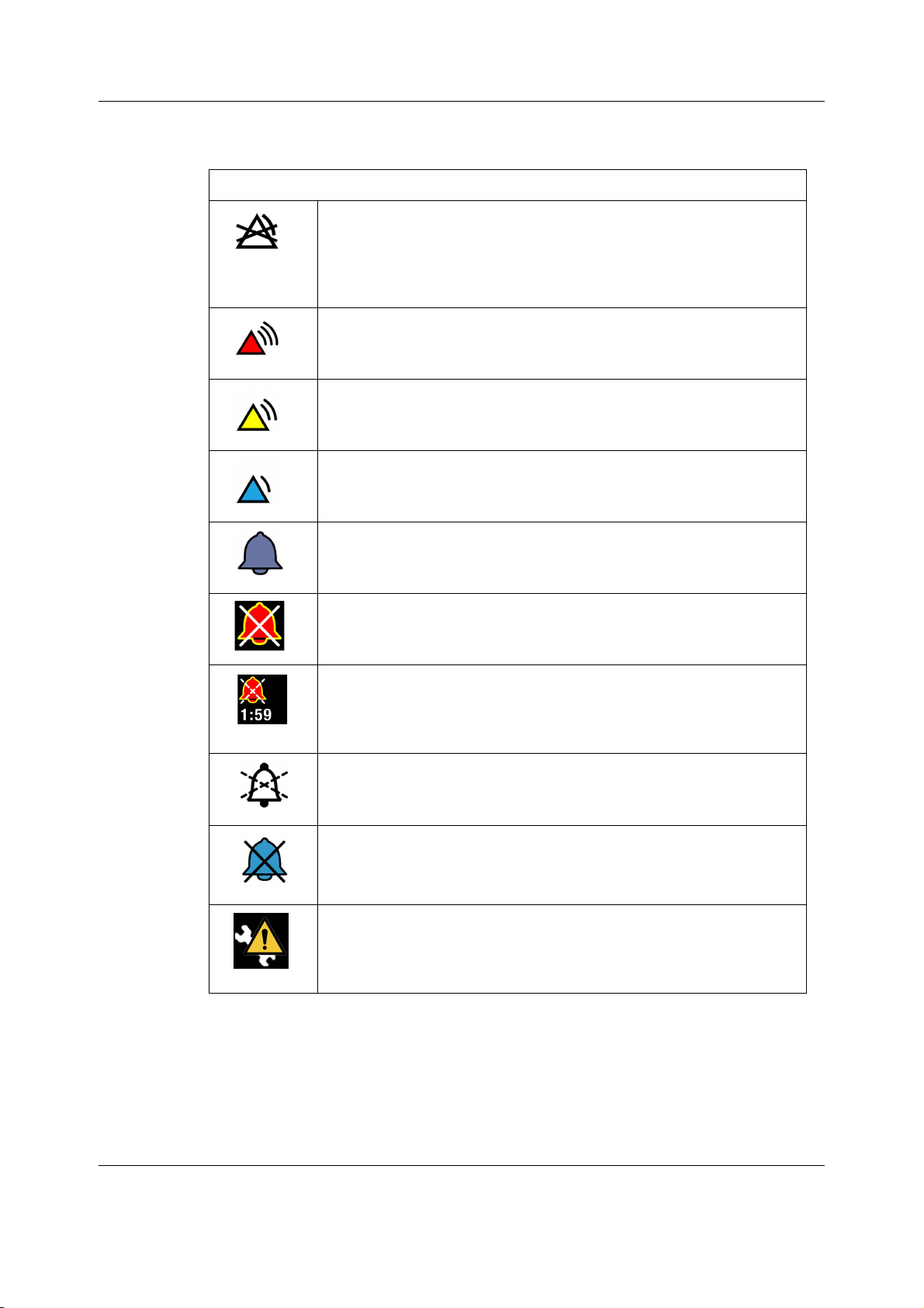
CARESCAPE Monitor B650
3.7 User interface symbols
The following symbols appear in the software user interface
Alarm off indicator. Displays in the upper right corner of the parameter
window and in the Alarms Setup menu when physiological alarms for this
parameter are turned off.
The symbol is not displayed at the central station or on a remote bedside
monitor.
Alarm priority indicator: High (red). Indicates a high priority alarm.
Alarm priority indicator: Medium (yellow). Indicates a medium priority
alarm.
Alarm priority indicator: Low (cyan). Indicates a low priority alarm.
Alarm volume icon. Adjust the minimum alarm tone volume.
Audio alarms off indicator - Displays in the upper left corner of the alarm
area when physiological audible alarms are turned off.
Audio alarms paused indicator with countdown timer - Indicates all audio
alarms are paused and the amount of time remaining for the alarm pause
period displays as a countdown timer.
Displays in the upper left corner of the screen.
Pause audio alarms - Selectable from the monitor’s main menu. Also an
indicator of a temporarily paused active audio alarm.
Low priority audio off alarm indicator, Displays in the upper left corner of
the alarm area.
Only with software version 2 host build 2.0.7 or earlier:
Configuration warning. Displays when the priority setting for HR/PR
high/low, or SpO2 low has been set to low. Check the alarm
configuration. Displays in the upper left corner of the alarm area.
34
2081903-001
Page 48
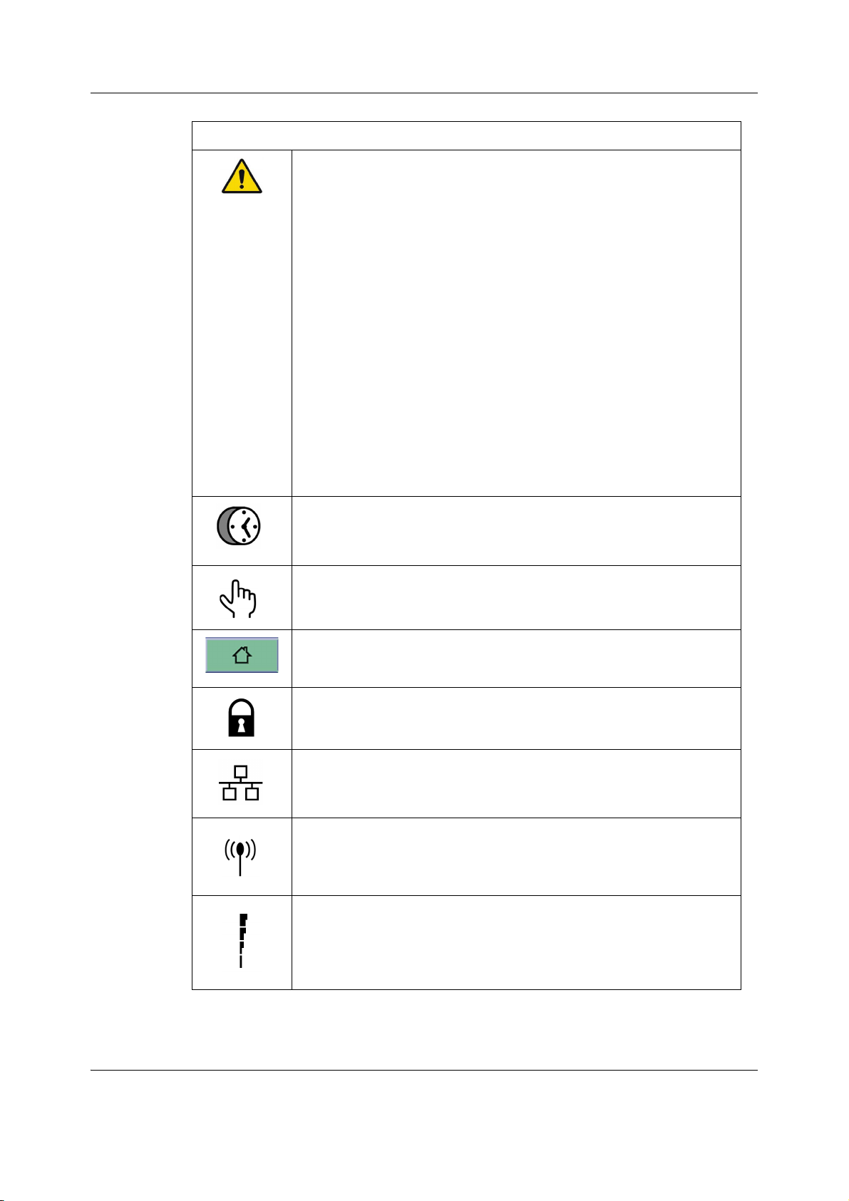
The following symbols appear in the software user interface
With software version 2 host build 2.0.7 or earlier:
General warning sign. Displays when the priority setting for HR/PR
high/low, or SpO2 low has been set to low.
Displays in the:
• Lower part of the parameter menu’s Alarms tab
• Priority column of the selected alarm in the Alarm Setup > Alarm
Priorities.
With software version 2 host build 2.0.8 or later:
General warning sign. Displays when the priority setting for Tachy/Brady
PR high/low or HR/PR high/low, or SpO2 low has been set to low, or when
the low priority volume is set to 0.
Displays in the:
• Upper left corner of the screen
• Lower part of the parameter menu’s Alarms tab
• Priority column of the selected alarm in the Alarm Setup > Alarm
Priorities.
System overview
Reminder volume icon. Adjust the volume of the tone that sounds every
two minutes when audio alarms are turned off.
Touch volume icon. Adjust the volume of the tone that sounds when a
user touches a touchscreen display.
Home icon. Close all menus/applications displayed on the patient
monitor.
Locking setting indicator. Indicates this setting is locked and cannot be
adjusted.
Network connection indicator. Indicates the patient monitor is connected
to the Local Area Network (LAN).
Network connection indicator. Indicates the monitor is connected to the
Wireless Local Area Network (WLAN).
Network (WLAN) signal strength. The number of segments corresponds to
the signal strength: four segments indicate strong signal, one segment
weak signal.
35
2081903-001
Page 49
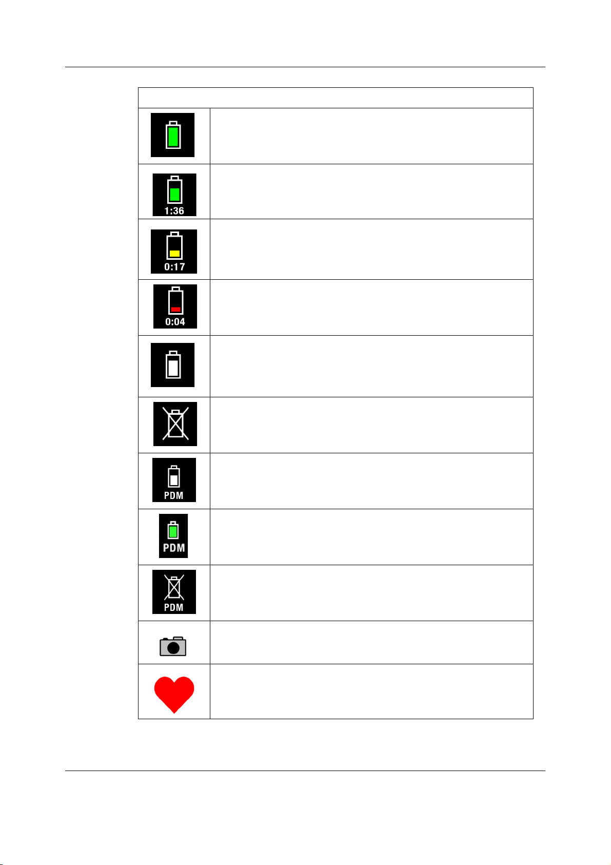
CARESCAPE Monitor B650
The following symbols appear in the software user interface
Monitor battery is full.
Monitor battery (green). The higher the charge, the bigger the green bar
within the symbol. Numbers indicate the remaining run time.
Monitor battery (yellow). This symbol and a message indicating low
battery charge appear when there is less than 20 minutes of run time left.
Monitor battery (red). This symbol and a message indicating empty
battery appear when there is less than 5 minutes of run time left.
Monitor battery is charging. There is a white running bar inside the
symbol.
Monitor battery failure indicator. Indicates a missing battery or a battery
failure.
PDM battery charging indicator. Indicates that the PDM battery is
charging.
PDM battery gauge indicator. Indicates the charge level of the battery.
PDM battery failure indicator. Indicates the battery is not available for use.
Snapshot indicator. Indicates the event has an associated snapshot.
36
2081903-001
Beat volume icon. Adjust the volume of the QRS beep tone. Also the beat
source indicator. Displays next to the selected beat source.
Page 50
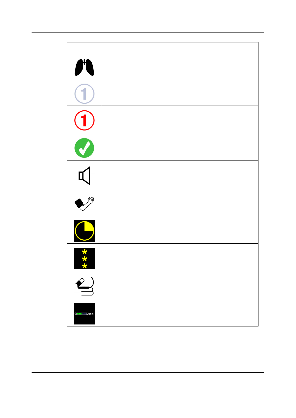
The following symbols appear in the software user interface
Respiration indicator. Indicates a breath is detected by the impedance
respiration algorithm.
BIS and Entropy sensor impedance check indicator (gray). Displays for
each sensor as the impedance check is in progress.
BIS and Entropy sensor impedance check error indicator (red). Indicates
the specified sensor failed the impedance check.
BIS and Entropy sensor impedance check passed indicator. Indicates the
specified sensor passed the impedance check.
Completed NIBP volume icon. Adjust the volume of the tone that sounds
when an NIBP measurement result is available.
System overview
Manual NIBP icon. Start a manual NIBP measurement.
Nellcor OxiMax SatSeconds indicator. Indicates the amount of time the
SpO
saturation is outside the limits before alarms are generated.
2
signal strength indicator. Indicates the signal strength, with three
SpO
2
asterisks indicating the strongest signal.
NMT Stimulus beep volume icon. Adjust the volume of the tone that
sounds when a stimulus pulse is generated.
Progress bar. Indicates the amount of time remaining until the next
automatic measurement.
37
2081903-001
Page 51

CARESCAPE Monitor B650
For your notes:
38
2081903-001
Page 52
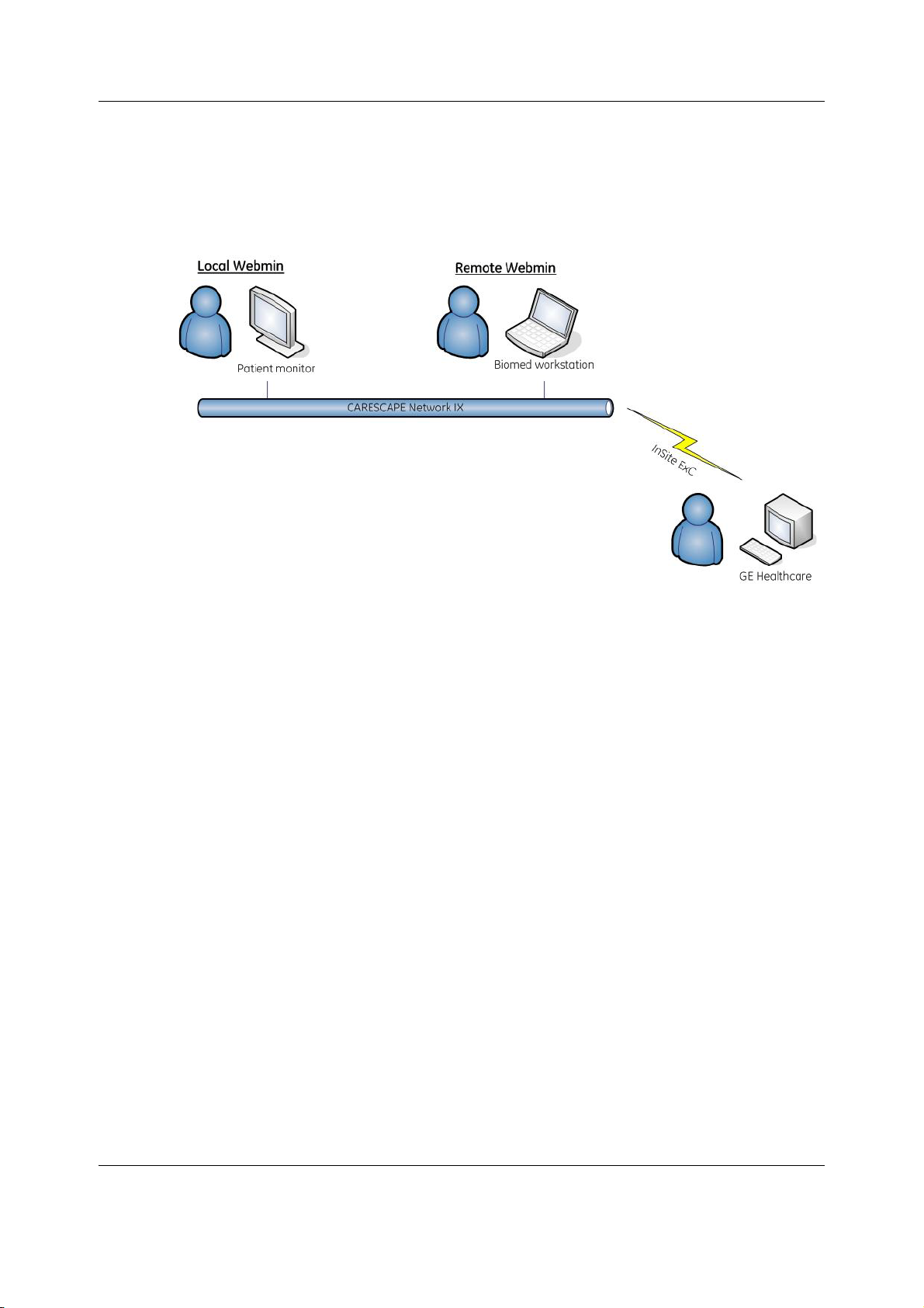
Using Webmin service interface
4 Using Webmin service interface
Webmin is a browser-based service interface that is used to configure the platform settings of
the patient monitor and to diagnose and retrieve system information for maintenance and
troubleshooting.
Local access to Webmin
You can access Webmin locally through the integrated browser on the patient monitor or from
a configured service PC that is connected to the patient monitor with an Ethernet crossover
cable. Depending on the monitor hardware configuration, the crossover cable is connected
either to the IX connector or to the MC connector.
Remote Webmin
You can access Webmin remotely from a configured service PC that is connected to the patient
monitor over the IX Network.
Requirements for service PC
• Network board with Ethernet port and TCP/IP network installed.
• Internet Explorer V6 or later.
4.1 Local access to Webmin using the integrated browser
on the patient monitor
NOTE: A USB keyboard and mouse are needed to access the integrated Webmin browser.
1. Select Monitor Setup > Service. The local browser opens and displays the Login to
Webmin dialog box.
39
2081903-001
Page 53
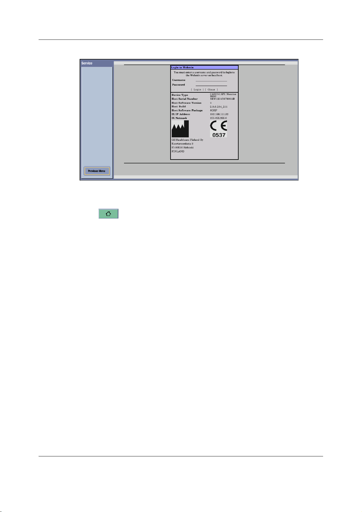
CARESCAPE Monitor B650
2. Continue to 4.5. Login to Webmin.
Closing Webmin
Select to close Webmin and return to the main display.
4.2 Local access to Webmin with a service PC connected
to the IX connector
You can access Webmin locally by connecting an Ethernet crossover cable between the
service PC and the IX connector of the patient monitor.
NOTE: This connection method is supported only if the monitor is equipped with the Advanced
Interface Board that provides both the IX and the MC connectors.
NOTE: If you disconnect the patient monitor from a live IX Network when a patient is admitted,
you will temporarily lose the services provided by the IX Network, e.g., access to the IX printers
and MUSE reports.
WARNING Non-medical equipment does not provide the same level of protection
against electrical shock. Do not touch the patient and any part of
non-medical equipment at the same time. Some examples of non-medical
equipment are laser printers and non-medical computers.
1. Connect a service PC to the IX connector on the patient monitor using a crossover cable.
2. In patient monitor, select Monitor Setup > Service. The local browser opens and displays
the Login to Webmin dialog box.
3. Record the IX IP address of the patient monitor:
IX IP address: ______________________
IX Netmask: ______________________
40
2081903-001
Page 54
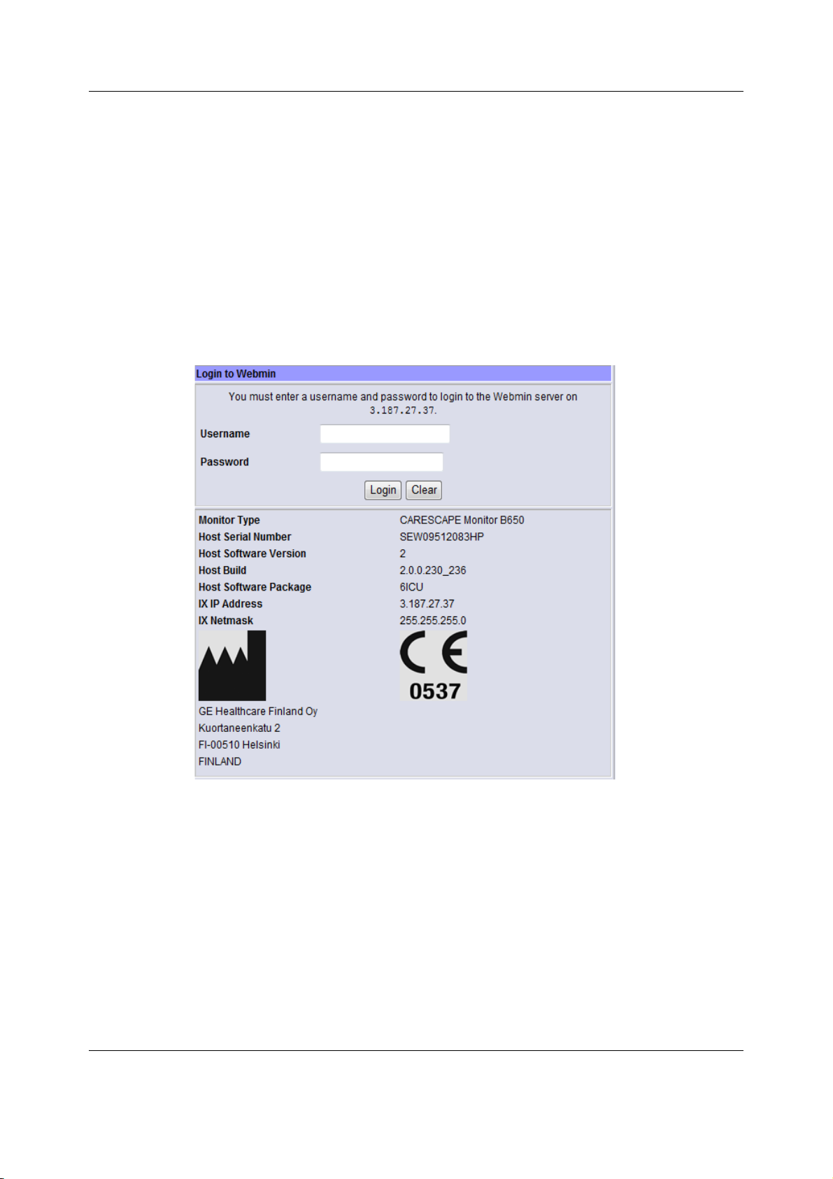
Using Webmin service interface
NOTE: If the IX IP address field is shown as 0.0.0.0., you need to configure the patient monitor’s
IX Network address first. Access Webmin using the integrated browser and configure a static IP
address for the IX Network.
4. Configure the service PC’s IP address and subnet mask to the same network segment
with the patient monitor’s IX Network setting.
NOTE: For more information on how to configure the IP address, refer to the PC’s
documentation.
5. Launch a web browser on the service PC.
6. In the Address field, type https://[IX IP address]:10000 and press Enter.
NOTE: [IX IP address] is the IX Network IP address of the patient monitor.
The Login to Webmin dialog box displays.
7. Continue to 4.5. Login to Webmin.
Closing Webmin
1. Restore the patient monitor’s original IX Network configuration and service PC’s network
settings if they were changed.
2. Disconnect the crossover cable from the patient monitor and from the service PC.
3. Reconnect the patient monitor back to the IX Network if applicable.
41
2081903-001
Page 55

CARESCAPE Monitor B650
4.3 Local access to Webmin with a service PC connected
to the MC connector
You can access Webmin locally by connecting an Ethernet crossover cable between the
service PC and the MC connector of the patient monitor.
NOTE: This connection method is available only if the monitor is equipped with the Standard
Interface Board that provides only the MC connector and the patient monitor is in a discharged
state.
NOTE: Ensure that there is no patient admitted, prior to disconnecting the monitor from a live
MC or S/5 Network.
NOTE: Normal patient monitoring is disabled in this connection method. You must exit the
maintenance mode to re-enable the normal patient monitoring mode. (Refer to “Closing
Webmin’ on page 43.)
1. Connect a service PC to the MC connector on the patient monitor using a crossover cable.
2. Select Monitor Setup > Service calibrations.
3. Log in with your biomed username and password and press Enter.
4. Record the MC IP Address shown next to the Start Maintenance Mode –menu button:
MC IP Address: ______________________
MC Netmask: ______________________
5. Select Start Maintenance Mode.
A screen saver with the text “Note: Monitor temporarily under maintenance” appears on
the screen.
6. Configure the service PC’s IP address and subnet mask to the same network segment
with the monitor’s MC Network.
NOTE: For more information on how to configure the IP address, refer to the PC’s
documentation.
7. Launch a web browser on the service PC.
8. In the Address field, type https://[MC IP address]:10000 and press Enter.
NOTE: [MC IP address] is the MC Network IP address of the patient monitor.
42
2081903-001
Page 56
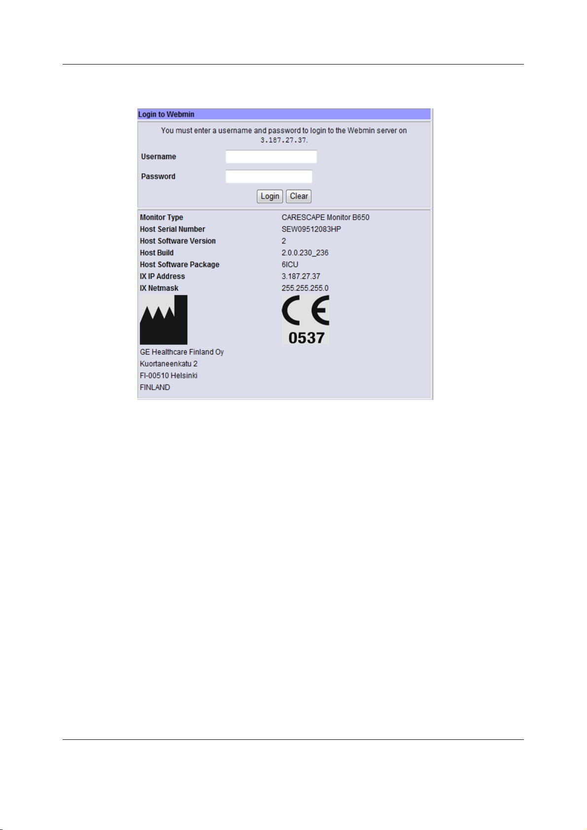
The Login to Webmin dialog box displays.
Using Webmin service interface
9. Continue to 4.5. Login to Webmin.
Closing Webmin
1. You can exit the monitor’s maintenance mode any time by pressing any keypad or
keyboard key, using the Trim Knob, using the touchscreen or clicking a mouse button. The
monitor will automatically restore the original network configuration to the S/5 or MC
Network and return to the normal monitoring mode.
2. Restore the original network settings in the service PC.
3. Disconnect the crossover cable from the monitor and from the service PC.
4. Reconnect the monitor back to the S/5 or MC Network if applicable.
4.4 Remote access to Webmin using a service PC over the
IX Network
NOTE: This connection method is supported only if the monitor is equipped with the Advanced
Interface Board that provides both the IX and the MC connectors and the monitor is connected
to a live IX Network.
1. Connect a service PC to the IX Network using a standard network cable.
2. In patient monitor, select Monitor Setup > Service. The local browser opens and displays
the Login to Webmin dialog box.
3. Record the IX IP address of the patient monitor:
IX IP address: ______________________
43
2081903-001
Page 57
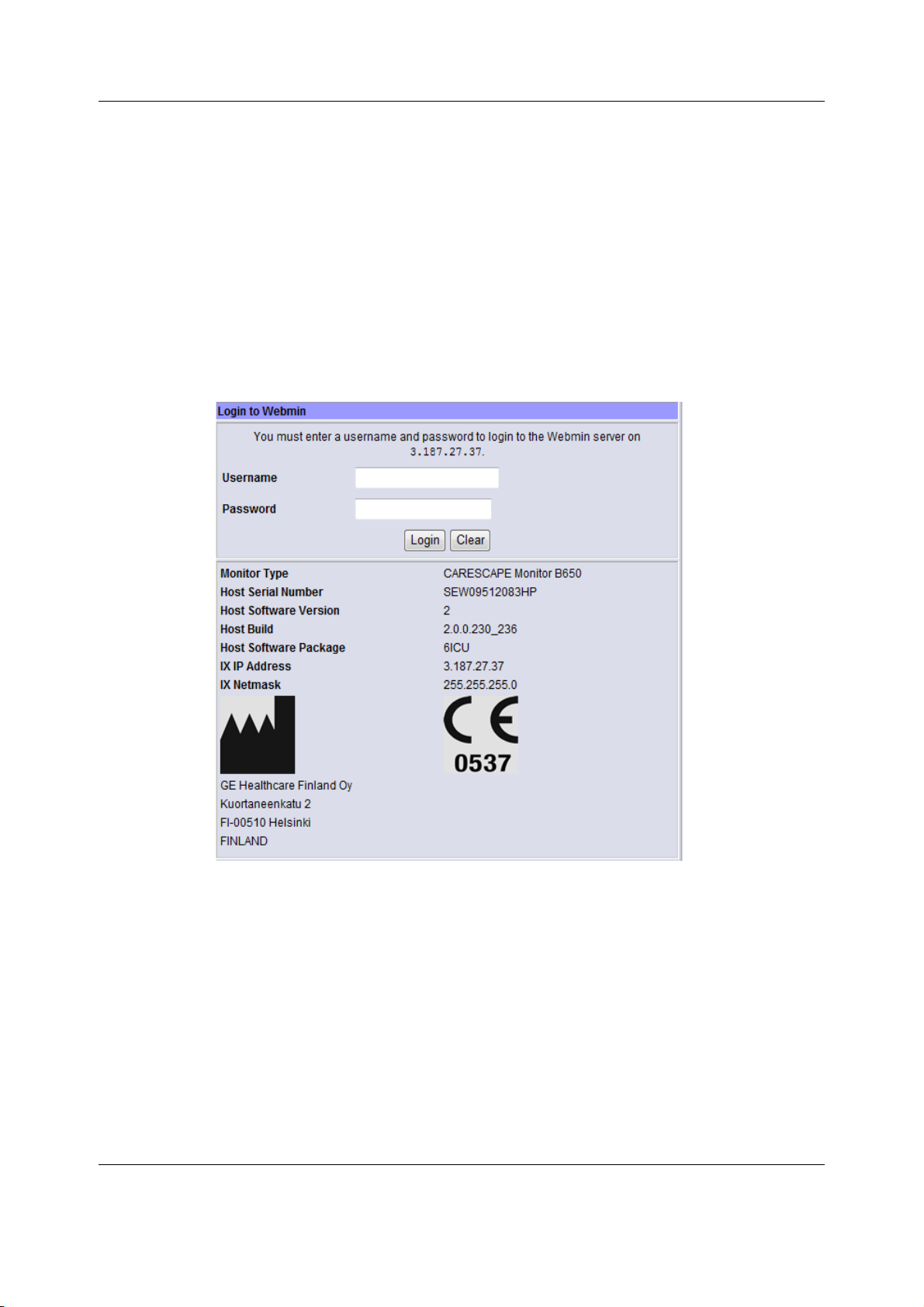
CARESCAPE Monitor B650
IX Netmask: ______________________
4. Configure the service PC’s IP address and subnet mask to the same network segment
with the patient monitor’s IX Network.
NOTE: For more information on how to configure the IP address, refer to the PC’s
documentation.
5. Launch a web browser on the service PC.
6. In the Address field, type https://[IX IP address]:10000 and press Enter.
NOTE: [IX IP address] is the IX Network IP address of the patient monitor.
The Login to Webmin dialog box displays.
7. Continue to 4.5. Login to Webmin.
Closing Webmin:
1. Restore the original network settings in the service PC.
2. Disconnect the service PC from the live IX Network.
4.5 Login to Webmin
1. In the Login to Webmin dialog box, type the username and password and select Login or
press Enter.
Username: biomed
Password: Change<space>Me
44
2081903-001
Page 58
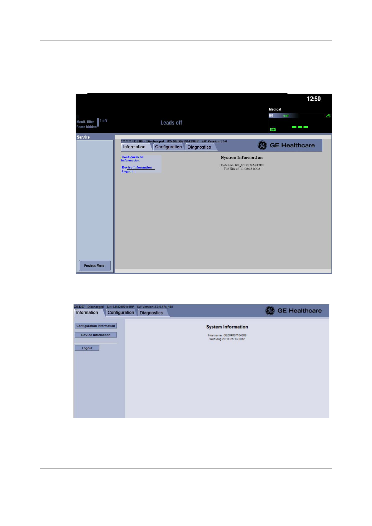
Using Webmin service interface
NOTE: Username and password are case sensitive.
NOTE: “Change Me” is the factory default password for the username “biomed”. Refer to
section 7.13. Changing passwords for details on how to change the default password.
The Webmin application opens and defaults to the Information tab.
Figure 1 Webmin user interface when accessed using the integrated browser
Figure 2 Webmin user interface when accessed using the service PC
45
2081903-001
Page 59
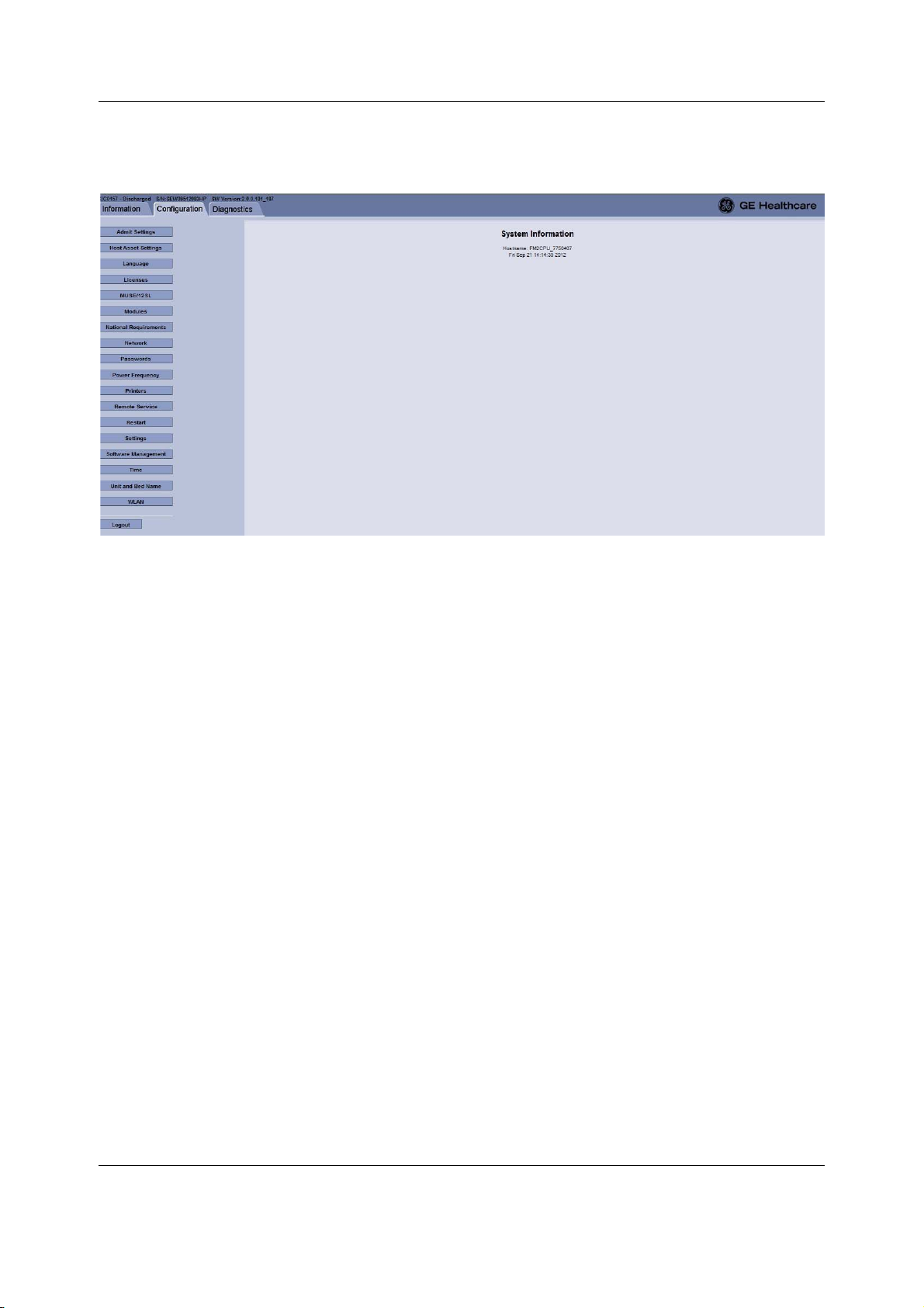
CARESCAPE Monitor B650
4.6 Webmin configuration modules
The Webmin service interface includes the following configuration modules. Select Help for
additional information related to each Webmin module.
Webmin module Use the module
Admit Settings to configure Patient ID Prefix and barcode settings.
Host Asset Settings to enter a host asset number and to view the host serial
number.
Language to select the language used in clinical user interface and
to select the keyboard locale setting for the
alphanumeric keyboard and the barcode reader.
Licenses to enable and activate a software package, to enable
and activate software features and to upload and
activate a license file.
MUSE/12SL to configure the host for sending and viewing 12SL
information.
Modules to configure some acquisition module specific settings
after corrective maintenance, or for administrative
purposes. These settings are saved to the permanent
memory of the related acquisition module and the
settings travel with the module from one patient monitor
to another.
Refer to the Module Frames and Modules Technical
Manual for detailed information how to change these
settings.
46
2081903-001
Page 60

Using Webmin service interface
Webmin module Use the module
National Requirements to activate France specific defaults for the ECG HR
adjustment range and the reminder beep behavior.
Network to select and configure the real-time network as the MC
Network (CARESCAPE Network) or S/5 Network. It also
allows the user to configure the IX Network settings.
Passwords to change the passwords for the biomed and clinical
users.
Power frequency to set the power line frequency.
Printers to configure the patient monitor to print to up to 12 laser
printers connected on the IX Network. There are
sub-modules for installing a printer, deleting a printer
and for printing a test page.
Remote Service to configure and control the Insite with Exc remote
service tool.
Restart to shutdown and restart the patient monitor
automatically via Webmin.
NOTE: The patient must be discharged in order to enable
monitor restart via Webmin.
Settings to transfer platform and/or clinical settings from one
patient monitor to another, to take backup copies of the
settings to an external device and to restore the settings
from an external device.
Software Management to update patient monitor and parameter module
software.
Time to set the date and time settings.
Unit and bed name to configure the care unit name and bed name for
patient monitors that are configured to connect to the
MC Network.
WLAN to configure the WLAN client settings for the MC
Network or S/5 Network.
47
2081903-001
Page 61
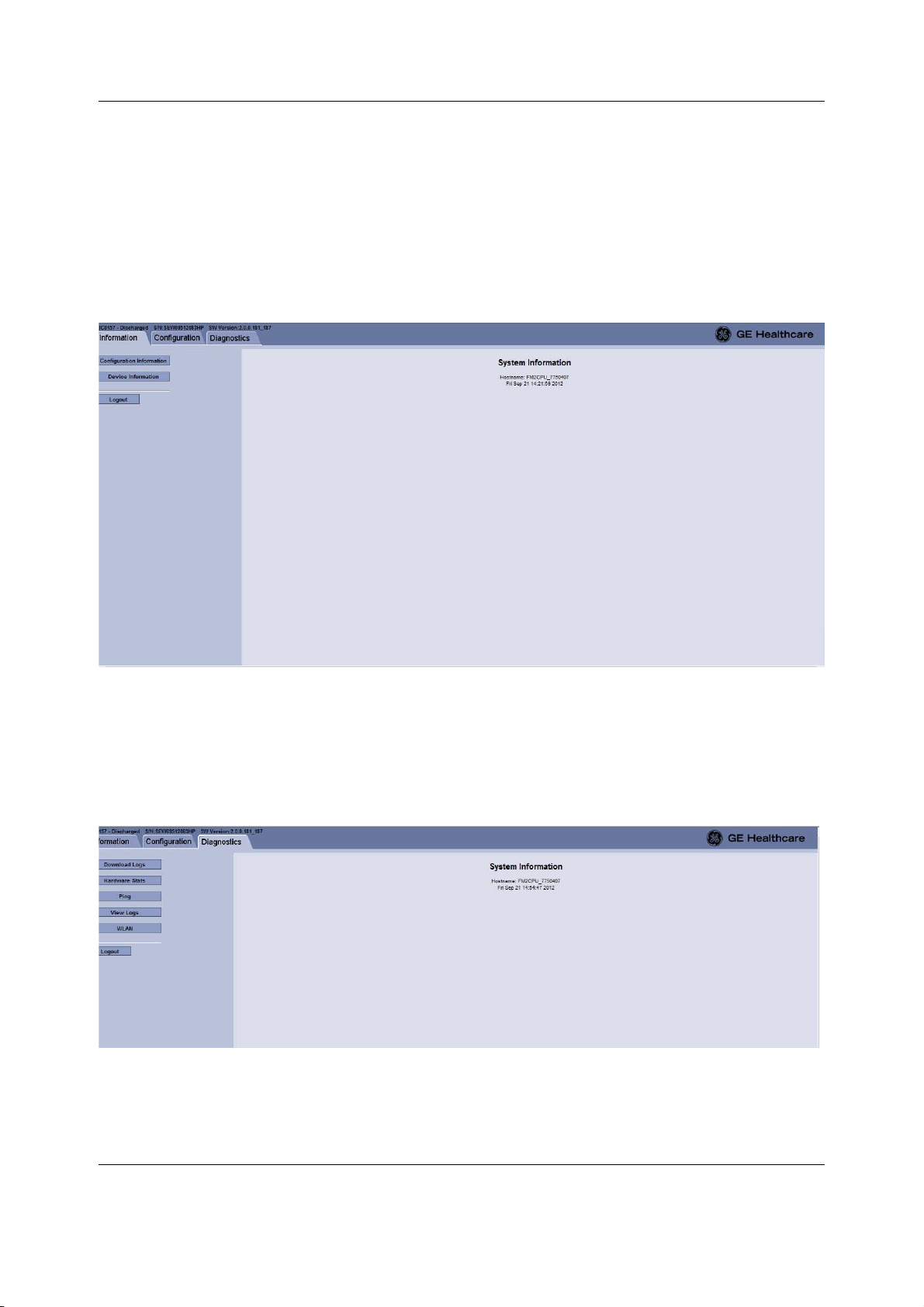
CARESCAPE Monitor B650
4.7 Webmin information modules
The Webmin information modules provide useful information about the patient monitor setup
especially for troubleshooting.
The Configuration Information module shows the current platform configuration of the patient
monitor and the connected peripheral devices.
The Device Information module shows the hardware and software information of the patient
monitor and the connected peripheral devices.
4.8 Webmin diagnostics modules
Access Webmin service interface to view hardware statistics, ping a network device, view
WLAN diagnostics and view or download log files.
The Hardware Statistics module displays several internal voltages, temperatures and power
consumption.
48
2081903-001
Page 62

Using Webmin service interface
Ping a TCP/IP network device- Use this Webmin feature to verify connectivity with a network
device on the MC Network and IX Network.
Log files - The patient monitor collects information about different system events and errors to
log files. These log files help troubleshooting problems in the patient monitor and the
connected peripheral devices.
WLAN diagnostics- Use this Webmin feature for troubleshooting WLAN related problems. This
Webmin module provides information about the WLAN driver, WLAN status and the detected
access points.
49
2081903-001
Page 63

CARESCAPE Monitor B650
For your notes:
50
2081903-001
Page 64

Pre-installation requirements
5 Pre-installation requirements
This chapter specifies the pre-installation requirements for the patient monitor.
5.1 Unpacking
1. Confirm that the packing box is undamaged. If the box is damaged, contact the shipper.
2. Open the top of the box and carefully unpack all components.
3. Confirm that all components are undamaged. If any of the components is damaged,
contact the shipper.
4. Confirm that all components are included. If any of the components is missing, contact
your GE Healthcare distributor.
WARNING EXCESSIVE LEAKAGE CURRENT - If the device has been transported or stored
outside operating temperature range allow it to stabilize back to operating
temperature range before removing it from the plastic bag.
CAUTION PACKAGING DISPOSAL - Dispose of the packaging material, observing the
applicable waste control regulations.
5.2 Compatibility check
Verify the compatibility of all system components prior to the installation of the patient
monitor.
• Refer to the patient monitor’s supplemental information manual for a list of compatible
network and bedside devices.
• Refer to the patient monitor’s supplemental information manual for a list of compatible
supplies and accessories.
• Refer to the patient monitor’s supplemental information manual and Unity Network
Interface Device (ID) Operator's Manual to see compatible peripheral devices.
WARNING BEFORE INSTALLATION - Compatibility is critical to safe and effective use of
this device. Please contact your local sales or service representative prior to
installation to verify equipment compatibility.
WARNING INTERFACING OTHER EQUIPMENT - Connect only items that are specified as
part of the system and as compatible. For more information, see the
CARESCAPE Modular Monitors Supplemental Information Manual.
WARNING Before connecting an interfacing module to the device, verify compatibility.
Verify the connectivity of device interfaces before using the equipment.
Verify the compatibility of software versions before using the equipment.
WARNING Do not use identical measurement modules or modules that map a
measurement to the same channel or parameter window. If such modules
have been connected, remove the module that has been most recently
connected. You can also remove both modules and re-connect the new
module after five seconds.
51
2081903-001
Page 65

CARESCAPE Monitor B650
WARNING The use of accessories, transducers and cables other than those specified
may result in increased emissions or decreased immunity performance of
the equipment or system.
WARNING For detailed instructions and information regarding supplies and
accessories, always refer to their own instructions for use.
5.3 Network infrastructure
Ensure that the applicable network infrastructure is in place prior to the installation of the
patient monitor.
Acquire the network configuration information from the hospital IT or the related project
documentation and installation files.
5.3.1 MC Network
• The MC Network infrastructure shall be installed according to the CARESCAPE Network
Configuration Guide.
• The installation site of the patient monitor shall have a wall jack and a network patch
cable for the MC Network.
• Refer to the sections 7.2.2. Selecting and configuring CARESCAPE Network and 7.4. Setting
unit and bed name to see the configuration information you need to have available to
configure the patient monitor to the MC Network.
5.3.2 Wireless MC Network
• The wireless MC Network infrastructure shall be installed according to the CARESCAPE
Wireless Network Configuration Guide.
• Ensure that the wireless coverage area is adequate for the installation.
• Refer to the sections 7.2.2. Selecting and configuring CARESCAPE Network, 7.2.4.
Configuring WLAN and 7.4. Setting unit and bed name to see the configuration
information you need to have available to configure the patient monitor to the wireless
MC Network.
5.3.3 S/5 Network
• The S/5 Network shall be installed according to the S/5 Network Installation Guide. Refer
to the iCentral and iCentral Client Service Manual for iCentral installation instructions.
• The installation site of the patient monitor shall have a wall jack and a network patch
cable for the S/5 Network.
• Refer to the section 7.2.3. Selecting and configuring S/5 Network to see the configuration
information you need to have available to configure the patient monitor to the wired S/5
Network.
5.3.4 S/5 Wireless Network
• The S/5 Wireless Network shall be installed according to the S/5 Network Installation
Guide. Refer to the iCentral and iCentral Client Service Manual for iCentral installation
instructions.
• Ensure that the wireless coverage area is adequate for the installation.
52
2081903-001
Page 66

• Refer to the sections 7.2.3. Selecting and configuring S/5 Network and 7.2.4. Configuring
WLAN to see the configuration information you need to have available to configure the
patient monitor to the S/5 Wireless Network.
5.3.5 IX Network
• The IX Network infrastructure shall be installed according to the CARESCAPE Network
Configuration Guide.
• The installation site of the patient monitor shall have a wall jack and a network patch
cable for the IX Network.
• Refer to the section 7.2.2. Selecting and configuring CARESCAPE Network to see the
configuration information you need to have available to configure the patient monitor to
the IX Network.
• Refer to the following sections for the information you need to have available for:
− 7.5. Configuring printers for IX printer configuration
− 7.6. Configuring MUSE/12SL
− 7.15.1. Configuring the remote service for Insite with Exc configuration.
5.4 Installing the mounting hardware
Pre-installation requirements
Ensure that all the applicable/ required mounting hardware is properly installed prior to the
installation of the patient monitor:
• Mounting hardware for the patient monitor, either for a stand-alone installation or for an
installation to an anesthesia machine or to a ventilator.
• Mounting hardware for the PSM module
• Mounting hardware for the PDM module
• Mounting hardware for the displays
• Mounting hardware for the Unity Network ID connectivity device
NOTE: Refer to the CARESCAPE Modular Monitors Mounting Solutions to identify the compatible
mounting hardware for each system component above.
WARNING Use only manufacturer specified mounts.
5.5 Unity Network ID connectivity device installation
The Unity Network ID connectivity device shall be properly installed, configured and tested
according to the Unity Network ID Connectivity Device Service Manual prior to connecting it to
the patient monitor.
Make sure that the Unity Network ID connectivity device is configured as follows:
• IP address is 192.168.253.x, where x is a number between 2 and 254.
• Netmask is 255.255.255.0
• The location of the Unity Network ID is set to a value other than the default (XXXX-XXX).
For example, BAY3|UNID3+.
Refer to the Unity Network Interface Device (ID) Service Manual for instructions on checking
and changing the IP address.
53
2081903-001
Page 67

CARESCAPE Monitor B650
5.6 Power and environmental requirements
Check the patient monitor’s supplemental information manual for power and environmental
requirements.
WARNING Operation of the monitor outside the specified performance range may
cause inaccurate results.
CAUTION Do not use or store equipment outside the specified temperature, humidity, or
altitude ranges.
Power requirements
• The installation site shall have hospital-grade grounded power outlets and power cords
for all system components.
• Verify that the power outlet is wired correctly according to the country’s electrical code
standard.
WARNING EXCESSIVE LEAKAGE CURRENT - A display or printer that is a non-medical
grade device and is used within the patient environment, must always be
powered from an additional transformer providing at least basic isolation
(isolating or separating transformer). Using without an isolating
transformer could result in unacceptable enclosure leakage currents.
Environmental requirements
• Install the patient monitor to a location that meets the specified environmental
requirements of operating temperature, humidity and atmospheric pressure.
• Set up the device in a location which affords sufficient ventilation. The ventilation
openings of the device must not be obstructed.
EMI & RFI interference:
WARNING Do not use the monitor in high electromagnetic fields (for example,
during magnetic resonance imaging).
WARNING Other equipment may interfere with the system, even if that other
equipment complies with CISPR emission requirements.
CAUTION EMC - Magnetic and electrical fields are capable of interfering with the proper
performance of the device. For this reason make sure that all external devices
operated in the vicinity of the monitor comply with the relevant EMC
requirements. X-ray equipment or MRI devices are a possible source of
interference as they may emit higher levels of electromagnetic radiation.
Changes or modifications to this device/system not expressly approved by GE
may cause EMC issues with this or other equipment. This device/system is
designed and tested to comply with applicable standards and regulations
regarding EMC and needs to be installed and put into service according to the
EMC information stated as follows: This device/system is suitable for use in all
establishments other than domestic and those directly connected to the public
low-voltage power supply network that supplies buildings used for domestic
purposes. Mains power should be that of a typical commercial or hospital
environment. Device is compliant to Class A.
54
2081903-001
Page 68

Pre-installation requirements
CAUTION Use of known RF sources, such as cell/portable phones, or other radio
frequency (RF) emitting equipment near the system may cause unexpected or
adverse operation of this device/system. Consult qualified personnel regarding
device/system configuration.
• The patient monitor should be isolated from sources of strong electromagnetic and radio
frequency interference.
NOTE: Refer to the patient monitor’s supplemental information manual for more information.
55
2081903-001
Page 69

CARESCAPE Monitor B650
For your notes:
56
2081903-001
Page 70

Hardware installation
6 Hardware installation
CAUTION LOSS OF MONITORING - Leave space for circulation of air to prevent the
monitor from overheating. The manufacturer is not responsible for damage to
equipment caused by improperly vented cabinets, improper or faulty power, or
insufficient wall strength to support equipment mounted on such walls.
WARNING The parameter modules are not able to withstand unpacked drops from a
height of 1 m without damage. If a module is dropped, please service it
before taking it back into use.
WARNING After transferring or reinstalling the monitor, always check that it is
properly connected and all parts are securely attached.
WARNING SITE REQUIREMENTS - Do not route cables or tubing in a way that they may
present a stumbling hazard.
WARNING EXPLOSION - Do not use this equipment in the presence of flammable
anesthetics, vapors or liquids.
WARNING EXCESSIVE TOUCH CURRENT - To avoid excessive patient leakage current,
do not simultaneously touch the patient and the electrical connectors
located at the rear panel of the monitor or within the module housing or
frames.
6.1 Installing a battery into the patient monitor and the
PDM module
The batteries for the patient monitor and the PDM module, if included, are shipped separately
and need to be installed and fully charged prior to taking into use.
WARNING PHYSICAL INJURY- Make sure the battery is completely inserted and the
battery door is completely closed. Falling batteries could seriously or fatally
injure neonatal or other vulnerable patients.
WARNING EXPLOSION OR FIRE -Using non-recommended batteries could result in
injury/burns to the patients or users. Only use batteries recommended or
manufactured by GE.
WARNING EXPLOSION HAZARD - Do not incinerate a battery or store at high
temperatures. Serious injury or death could result.
NOTE: Refer to section 10.4. Monitor battery maintenance in this manual for maintenance
instructions of the patient monitor battery. Refer to the Module Frames and Modules Technical
Manual for information about PDM battery maintenance.
6.1.1 Testing the battery charge
Before installing a battery, verify the battery’s state of charge. Press the green TEST button on
the battery. The number of charge level indicator LEDs that illuminate indicates the
approximate charge remaining in the battery.
− Four LEDs illuminated: 75% – 100% of full-charge capacity.
57
2081903-001
Page 71
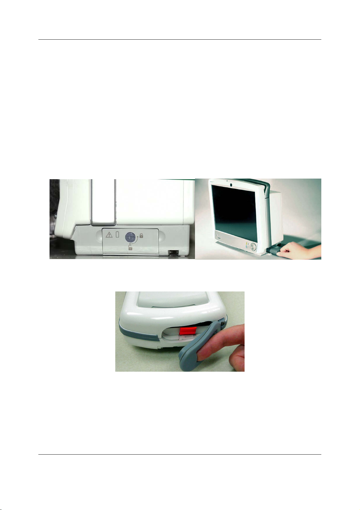
CARESCAPE Monitor B650
− Three LEDs illuminated: 50% – 74.9% of full-charge capacity.
− Two LEDs illuminated: 25% – 49.9% of full-charge capacity.
− One LED illuminated: 10% – 24.9% of full-charge capacity.
− One LED flashing: < 10% of full-charge capacity remaining.
NOTE: Before taking the patient monitor into use for the first time, the battery should be fully
charged. Keep the PDM connected to the patient monitor and the patient monitor connected to
the AC mains until the batteries are fully charged.
6.1.2 Installing the battery into the patient monitor
1. Open the battery cover by turning the battery cover lock 90 degrees clockwise.
2. Insert the battery with the test indicator side up and the connector end first all the way
into the battery slot. To remove the battery, pull it out from the cord.
3. Push the cover back up and lock it in place by turning the lock 90 degrees
counter-clockwise.
6.1.3 Installing the battery into the PDM module
1. Open the battery door by gently pulling on the battery door pull tab.
2. Pull the battery tray out of the PDM using the battery tray strap.
3. Insert the battery with the
TEST button facing up and the arrow pointing into the PDM.
58
2081903-001
Page 72
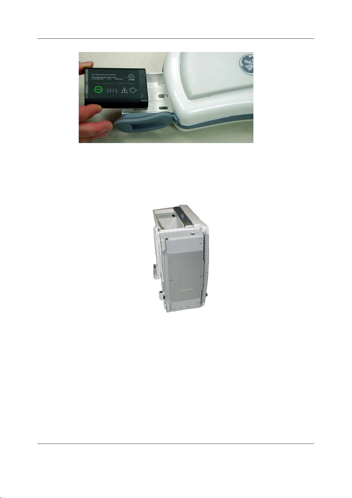
4. Press the battery door closed until it seals the battery compartment.
6.2 Mounting the patient monitor
The patient monitor has an integrated GCX mounting plate. This facilitates all mounting options
for the patient monitor. Refer to the CARESCAPE Modular Monitors Mounting Solutions to
identify the compatible mounting hardware for the patient monitor.
Hardware installation
Install the patient monitor to the mounting hardware according to the installation instructions
included with the mounting hardware.
WARNING Never install equipment above the patient.
WARNING Use only manufacturer specified mounts.
WARNING To prevent liquids from entering the monitor, do not tilt the monitor more
than +/-15 degrees.
CAUTION The device/system should not be used adjacent to, or stacked with, other
equipment. Consult qualified personnel regarding device/system configuration.
2081903-001
59
Page 73
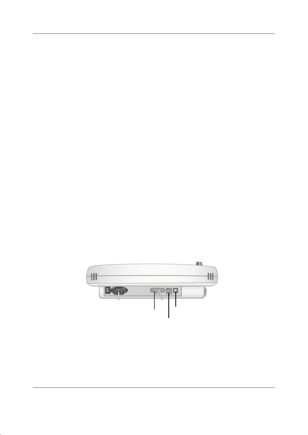
CARESCAPE Monitor B650
DVI-I connector
Type A USB ports
Type B USB port
6.3 Connecting a secondary display
The patient monitor supports one secondary, clone display.
WARNING Do not connect a monochrome display to the monitor. Visual alarm
indicators may not appear properly.
WARNING The secondary display will not sound the audible alarms.
WARNING To prevent liquids from entering the display, do not tilt the display more
than +/-15 degrees.
WARNING Use only manufacturer specified mounts.
NOTE: Refer to the patient monitor’s supplemental information manual for a list of compatible
secondary displays.
NOTE: Refer to the display's user manual for more information about the display installation.
NOTE: Ensure that the display is installed to the mounting hardware according to the
installation instructions included with the mounting hardware.
NOTE: Make sure that all cables are securely connected.
NOTE: Refer to section 7.1 for information about touchscreen calibration and display
adjustments.
NOTE: All installations should be compliant with IEC 60601-1-1 and local electrical codes.
NOTE: The patient monitor with a non-medical grade display, which is IEC 60950-rated or
equivalent, meets UL and IEC specifications if a medical grade isolation is used. If a
non-medical grade display is to be used, the configuration must meet the IEC 60601-1-1
standard. Refer to IEC 60601-1-1 for requirements if using non-medical grade displays in the
patient environment.
6.3.1 Connections to D15K and D19KT displays
The following instructions describe two methods to connect a D15K or D19KT display as a
secondary display.
A) Cable length is less than 5 meters
1. Connect one end of the DVI-D to DVI-D video cable to the DVI-I connector on the bottom
of the display and the other end to the DVI-I connector on the back of the patient monitor.
2. Connect the Type A plug of the standard USB cable to one of the downstream ports
(Type A USB port) on the back of the patient monitor.
3. Connect the Type B plug of the standard USB cable to the upstream port (Type B USB port)
on the bottom of the display.
60
2081903-001
Page 74
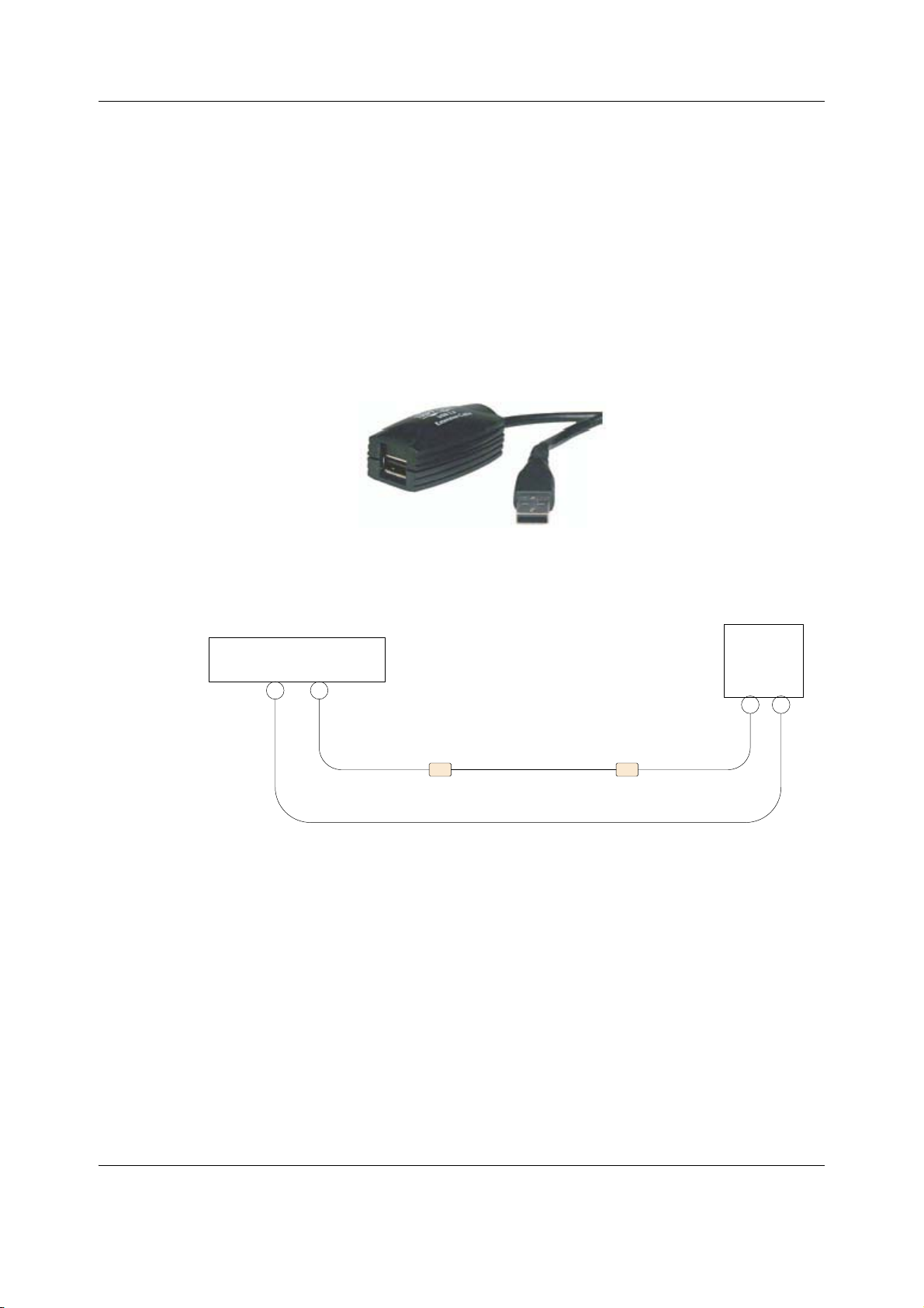
Hardware installation
Type A plug
Type A receptacle
USB extender
$WR' '9,'FRQQHFWLRQ
%WR& 86%UHPRWH86%H[WHQGHUVUHTXLUHG
&$5(6&$3(0RQLWRU%
$ %
5HPRWH
GLVSOD\
& '
'9,,FDEOHPIW
VW
86%H[WHQGHU
FDEOHPIW
QG
86%H[WHQGHU
FDEOHPIW
6WDQGDUG86%
FDEOHPIW
6LQJOHSRUW86%KXE 6LQJOHSRUW86%KXE
4. Secure the USB cables connections to the displays according to the instruction included
in the display package.
NOTE: A USB hub should not be used to connect the USB touchscreen to the patient monitor.
B) Cable length is 5 to 15 meters
If complete isolation is not required, this method will provide the most cost effective means of
extending your USB installation. This type of installation should not be used for connections to
non-medically used rooms according to IEC 60601-1-1.
Displays may be extended up to 15 meters from the patient monitor using the following cables:
− 15-meter DVI-I to DVI-I video cable (p/n 2042766-001).
− 5-meter USB extender (p/n 2042768-001).
− Standard USB-A to USB-B cable, up to 5 meters.
In the following example, two 5-meter USB extenders, plus a standard 5-meter USB cable
extend the remote display up to 15 meters from the patient monitor.
USB-connection:
1. Connect the Type A plug of the 1st USB extender to one of the downstream ports (Type A
2. Connect the Type A plug of the 2nd USB extender to the Type A receptacle on the 1st USB
3. Connect the Type A plug of the standard USB cable to the Type A receptacle on the 2nd
4. Connect the Type B plug of the standard USB cable to the upstream port (Type B USB port)
USB port) on the back of the patient monitor.
extender.
USB extender.
on the bottom of the display.
61
2081903-001
Page 75
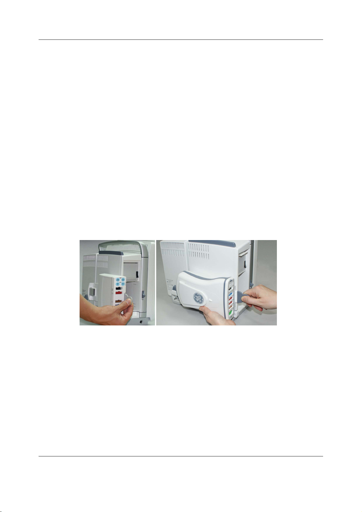
CARESCAPE Monitor B650
5. Secure the USB cables connections to the displays according to the instruction included
in the display package.
Video cable:
Connect one end of the 15-meter DVI-I to DVI-I video cable to the DVI-I connector on the
bottom of the display and the other end to the DVI-I connector on the back of the patient
monitor.
6.4 Installing parameter modules
Refer to the patient monitor’s supplemental information manual to verify compatible
parameter modules and to identify the parameter modules with identical measurements.
WARNING Ensure that the compact airway modules and CARESCAPE respiratory
modules are in vertical position when used. Tilting them may result in
erroneous readings.
6.4.1 Installing a PSM or a PDM module
You can install a PSM or a PDM module either to the patient monitor or to a remote mounting
solution.
Connecting a PSM or a PDM module to the patient monitor
1. Connect a module by aligning it with the insertion guides on the pivoting module frame.
2. Push the module into the frame until it clicks and stops.
Installing a PSM module to a pole mount:
Ensure that the Pole Mount for PSM is properly installed to an IV pole according to the
installation guide included with the mounting hardware.
WARNING PHYSICAL INJURY- Take care when mounting devices to an IV pole. If a
device is mounted too high the IV pole may become unbalanced and tip
over.
1. Connect the PSM module to the Pole Mount for PSM as instructed in the accompanying
installation guide.
2. Connect the Module Bus Adapter for PSM to the PSM connector in the patient monitor.
3. Connect the cable from the Pole Mount for PSM to the Module Bus Adapter for PSM.
62
2081903-001
Page 76
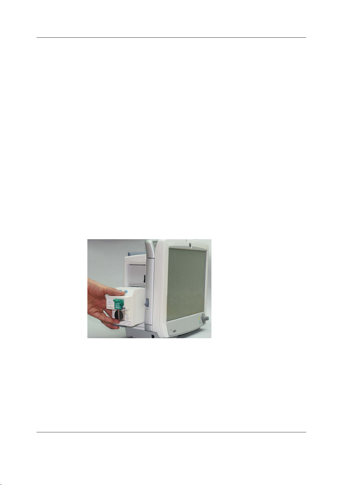
Hardware installation
Installing a PDM module to a mounting solution:
Ensure that the selected PDM mount is properly installed according to the installation
instructions included with the mounting hardware.
1. Connect the PDM module to installed mounting hardware as instructed in the
accompanying installation instructions.
2. Connect one end of the ePort cable to the PDM module ePort connector.
3. Connect the other end of the ePort cable to the ePort connector in the rear panel of the
patient monitor.
NOTE: The PDM module can be installed into a pole mount only if the monitor is equipped with
the Advanced Interface Board that provides the ePort connector.
WARNING PHYSICAL INJURY — Do not install the PDM above a patient. Make sure the
battery is completely inserted and the battery door is completely closed.
Falling batteries could seriously or fatally injure neonatal or other
vulnerable patients.
WARNING PHYSICAL INJURY — Do not install the PDM above a patient. Leaks from the
battery cells can occur under extreme conditions. The liquid is caustic to the
eyes and skin. If the liquid comes in contact with eyes or skin, flush with
clean water and seek medical attention.
Installing E-modules to the patient monitor
1. Connect a module by aligning it with the insertion guide inside the module slot.
2. Push the module into the frame until it locks.
6.5 Connecting to the mains power
WARNING Use only AC power cords recommended or manufactured by GE.
WARNING EXCESSIVE LEAKAGE CURRENT - To avoid summation of leakage currents
when interfacing the device with other equipment, the devices may only be
interconnected with each other or to parts of the system when it has been
determined by qualified biomedical personnel that there is no danger to the
patient, the operator, or the environment as a result. In those instances
where there is any element of doubt concerning the safety of the connected
2081903-001
63
Page 77

CARESCAPE Monitor B650
devices, the user must contact the manufacturers concerned (or other
informed experts) for proper use. In all cases, safe and proper operation
should be verified with the applicable manufacturer's instructions for use,
and system standards IEC60601-1-1 must be complied with.
When interfacing the device with other equipment, the devices may only be interconnected
with each other or to parts of the system when it has been determined by qualified biomedical
personnel that there is no danger to the patient, the operator, or the environment as a result.
WARNING Do not under any circumstances remove the grounding conductor from the
power plug. Always check that power cord and plug are intact and
undamaged.
WARNING POWER SUPPLY — The device must be connected to a properly installed
power outlet with protective earth contacts only. If the integrity of the
protective earth conductor is in doubt, disconnect the monitor from the
power line, and use it with the battery option, if available. All devices of a
system must be connected to the same power supply circuit. Devices which
are not connected to the same circuit must be electrically isolated when
operated.
CAUTION POWER REQUIREMENTS - Before connecting the device to the power line, check
that the voltage and frequency ratings of the power line are the same as those
indicated on the device's label. If this is not the case, do not connect the system
to the power line until you adjust the device to match the power source. In
U.S.A., if the installation of this equipment will use 240V rather than 120V, the
source must be a center-tapped, 240V, single-phase circuit. This equipment is
suitable for connection to public mains as defined in CISPR 11.
If a non-medical grade display is used as a display within the patient environment it must
always be powered from an additional transformer providing at least basic isolation.
1. Connect power cords to the mains power supply inlet and to a wall outlet on all system
components that require AC mains power input.
2. Do not power on any devices.
NOTE: Be sure that all power cords are securely connected and that they are routed through
the retaining clips or cable clamps, as applicable.
64
2081903-001
Page 78
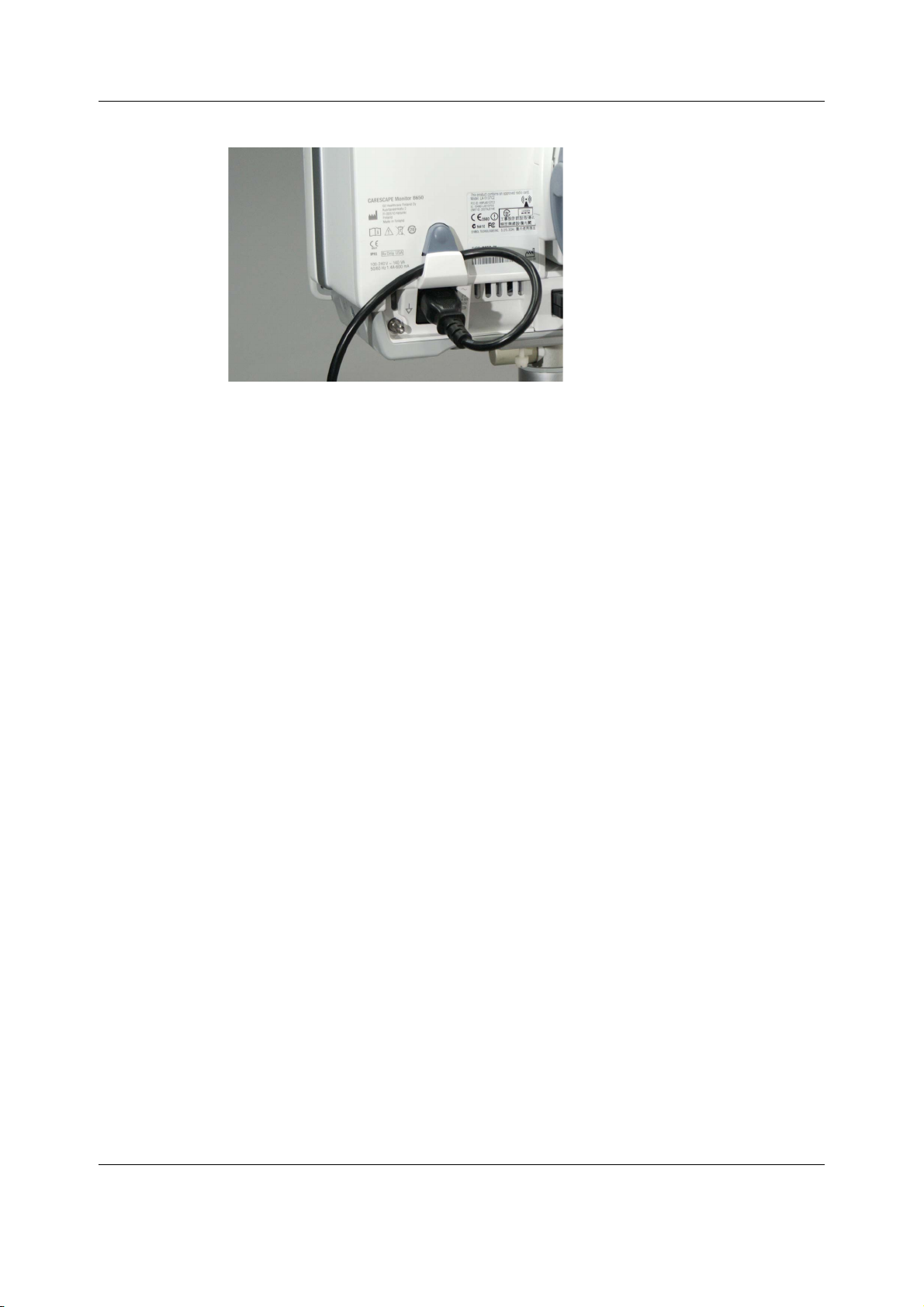
Hardware installation
6.6 Connecting to the MC Network or the S/5 Network
WARNING MISSED ALARMS - Do not use with iCentral software with Versions 5.0.3 and
earlier or with Mobile Care Server with Version 5.2 and earlier.
WARNING INCORRECT CALCULATIONS - Using the System with the Aware Gateway
software version 1.4 or earlier could result in incorrect patient height and
weight information. This could lead to incorrect drug dose calculations,
hemodynamic calculations, or oxygenation calculations. Prior to installing
the System, please contact the GE Healthcare Aware Gateway HL7
Integration Engineering Team or your GE Healthcare service representative
to verify or update your Aware Gateway configuration.
WARNING EXCESSIVE LEAKAGE CURRENT - Only devices that are specified compliant
with IEC 60950-1 or IEC 60601-1 may be connected to the Ethernet MC or IX
ports.
The patient monitor can be connected either to the wired MC Network or S/5 Network.
• Connect the MC Network or the S/5 Network patch cable to the network connector
labelled as “MC” in the rear panel of the patient monitor.
6.7 Connecting to the IX Network
• Connect the IX Network patch cable to the network connector labelled as “IX” in the rear
panel of the patient monitor.
NOTE: Connection to the IX Network is possible only if the monitor is equipped with the
Advanced Interface Board.
6.8 Connecting to a Unity Network ID connectivity device
Ensure that the Unity Network ID connectivity device is properly mounted, installed and
configured prior to connecting it to the patient monitor.
CAUTION INSTALLATION - To avoid accidental ingress of liquids, always mount the Unity
Network Interface Device (ID) in a vertical position with the connectors at the
bottom.
65
2081903-001
Page 79

CARESCAPE Monitor B650
• Connect a Unity Network ID connectivity device to the network connector labelled “ID” in
the re
ar panel of the patient monitor.
NOTE: Connection to the Unity Network ID connectivity device is possible only if the monitor is
equipped with the Advanced Interface Board.
WARNING Before connecting an interfacing module to the device, verify compatibility.
Verify the connectivity of device interfaces before using the equipment.
Verify the compatibility of software versions before using the equipment.
CAUTION The use of the wrong interface adapter may cause improper operation of the
supported peripheral device.
WARNING SINGLE PATIENT USE - All eight serial ports of the Unity Network Interface
Device (ID) must only be used on one patient.
6.9 Connecting USB devices
NOTE: The USB-connection to a D15K or D19KT secondary display reserves one of the USB
connectors in the rear panel of the patient monitor.
Connect the following devices to the USB ports in the rear panel of the patient monitor or at
the bottom of a D15K or D19KT display:
• Alphanumeric keyboard
•Mouse
•Remote control
• Barcode reader
NOTE: Always use a GE-supplied barcode reader for the CARESCAPE monitors. The barcode
reader comes pre-configured and is ready to connect. Refer to the included installation
instructions for more details.
WARNING Use only washable keyboard with at least IPX1 protection against ingress of
water.
6.10 Connecting iCollect and other data acquisition
systems
iCollect and other data acquisition systems can be connected to one of the USB connectors in
the rear panel of the patient monitor.
NOTE: Use the ATEN UC232A USB-to-serial Converter and PC serial interface cable to connect
iCollect and the other data acquisition systems to the patient monitor.
66
2081903-001
Page 80
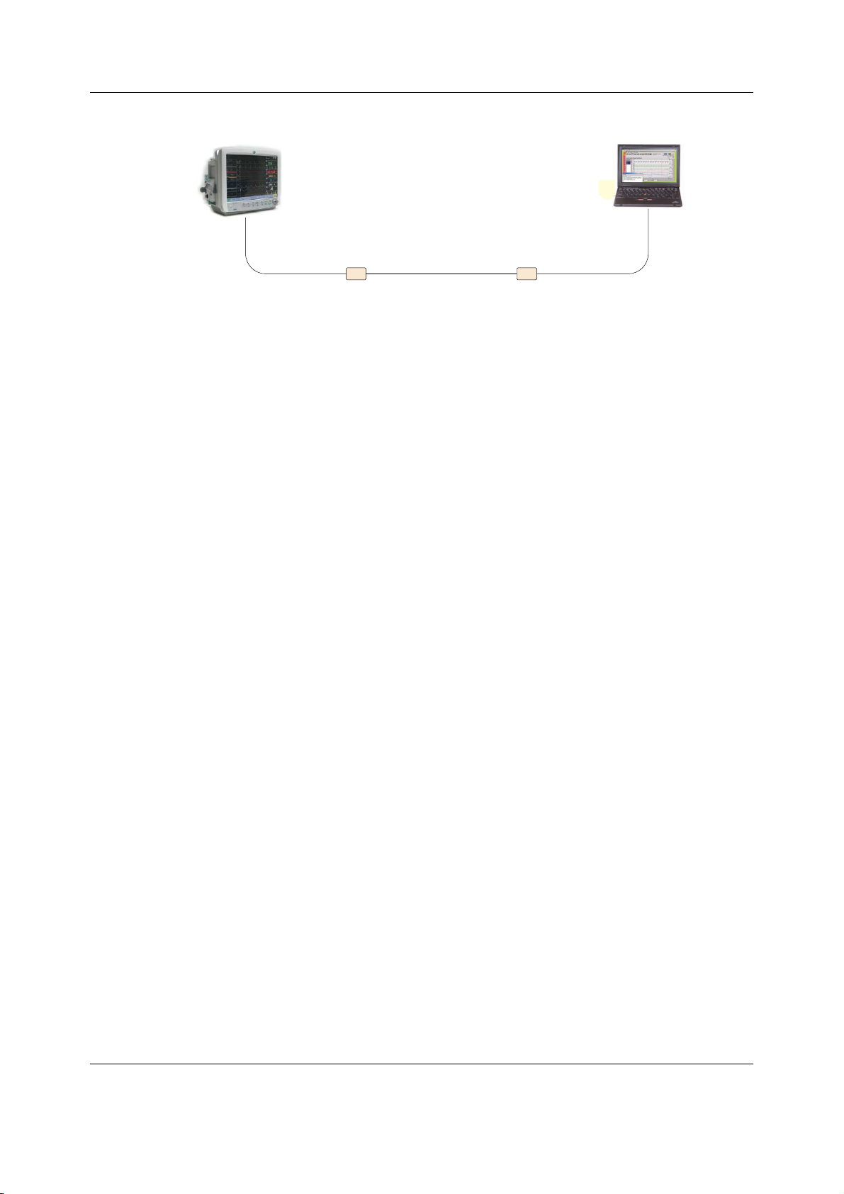
NOTE: Refer to the iCollect User's Manual for more information about the iCollect.
ϭ
Ɛƚ
h^ƚŽƐĞƌŝĂů
ĐŽŶǀĞƌƚĞƌ
WƐĞƌŝĂůŝŶƚĞƌĨĂĐĞ
ĐĂďůĞϴϴϭϭϲϳ
Ϯ
ŶĚ
h^ƚŽƐĞƌŝĂů
ĐŽŶǀĞƌƚĞƌŝĨ
ŶĞĞĚĞĚ
NOTE: Contact GE Healthcare Service to get more information about interfacing other data
acquisition systems to the patient monitor.
6.11 Connecting a remote-on cable
Remote-on connection allows you to power-up the patient monitor from the power switch of a
GE Healthcare anesthesia machine.
1. Connect the remote-on cable to the remote-on connector labelled as “X3” in the rear
panel of the patient monitor.
2. Connect the other end of the remote-on cable to the related connector in the anesthesia
machine. Refer to the related product documentation for details.
NOTE: Remote-on connection is possible only if the monitor is equipped with the Advanced
Interface Board that has the remote-on connector and if the anesthesia machine supports this
feature.
NOTE: Remote-on connection is possible only if the anesthesia machine supports this feature.
Hardware installation
NOTE: The remote on/standby function is disabled when the patient monitor is battery
powered.
6.12 Connecting a local printer to the IX connector
You can connect a local laser printer directly to the patient monitor’s IX connector with a
crossover cable.
1. Connect the Ethernet cable to the IX connector labelled as “IX” in the rear panel of the
patient monitor.
2. Connect the other end of the Ethernet crossover cable to the connector in the laser
printer.
NOTE: Connection to a local printer is possible only if the monitor is equipped with the
Advanced Interface Board that provides an IX Network connector.
NOTE: If the local printer is used within the patient environment it must always be powered
from an additional transformer providing at least basic isolation.
NOTE: Refer to the printer manual on how to install and configure the printer. The printer shall
be configured to communicate in the same subnet with the patient monitor’s IX Network
settings.
67
2081903-001
Page 81

CARESCAPE Monitor B650
WARNING EXCESSIVE LEAKAGE CURRENT - Laser printers are UL 60950/IEC 60950
certified equipment, which may not meet the leakage current requirements
of patient care equipment. This equipment must not be located in the
patient environment unless the medical system standard IEC 60601-1-1 is
followed. Do not connect a laser printer to a multiple socket outlet
supplying patient care equipment. The use of multiple socket outlet for a
system will result in an enclosure leakage current equal to the sum of all the
individual earth leakage currents of the system if there is an interruption of
the multiple socket outlet protective earth conductor.
WARNING Non-medical equipment does not provide the same level of protection
against electrical shock. Do not touch the patient and any part of
non-medical equipment at the same time. Some examples of non-medical
equipment are laser printers and non-medical computers.
68
2081903-001
Page 82

7 Configuration
The configuration of the patient monitor consists of platform configuration and clinical
configuration.
This chapter describes how to perform the platform configuration tasks needed to take the
patient monitor into use for the first time and the configuration tasks needed for administration
and maintenance thereafter.
For information on how to perform the clinical configuration, including care unit settings and
user profiles, refer to the patient monitor’s user’s manual.
7.1 Adjusting display
7.1.1 Adjusting the brightness of the integrated primary display
If needed, adjust the display brightness from the Monitor Setup > Brightness menu. Refer to
the patient monitor’s user’s manual for more information.
7.1.2 Calibrating a touchscreen
Configuration
NOTE: The touchscreen function of the integrated primary screen has been calibrated in the
factory. Re-calibration is typically needed only after replacing the uDOM or the touchscreen
sensor.
Calibrate the connected touchscreens, one by one, as follows:
1. Select Monitor Setup > Service Calibrations.
2. In the Enter Password dialog box, type the username and password and press
Username: biomed
Password: Change<space>Me
NOTE: Username and password are case sensitive.
NOTE: The factory default password for the username “biomed” is “Change Me”.
3. In the Service / Calibrations menu, select Touch Screen to calibrate the integrated
primary display or the connected secondary display.
4. The Touch calibration screen opens.
5. Touch the calibration mark or cross hair (+) in each corner of the screen, according to the
instructions shown on the screen.
7.1.3 Adjusting optional secondary display
If needed, adjust the picture on the display using the Auto Adjustment feature in the display’s
OSD menu. Refer to the display's user manual for details.
Enter.
7.2 Configuring the network
7.2.1 Configuring hostname
1. Log in to Webmin
2. Select Configuration > Network > Hostname.
The Hostname Configuration window opens.
The current hostname is shown in the Current Value column.
69
2081903-001
Page 83

CARESCAPE Monitor B650
3. Enter the new hostname in the Change Value to column.
NOTE: The hostname is a unique, 4 to 32 character long identifier of a patient monitor in
the network. Use alphanumeric characters A-Z, a-z, 0-9. The hostname may include also
characters “-” and “_”, but it can't start or end with these characters.
4. Select Save.
The hostname configuration will take effect immediately.
7.2.2 Selecting and configuring CARESCAPE Network
To select CARESCAPE Network MC for the real-time network infrastructure:
1. Log in to Webmin.
2. Select Configuration > Network > Wired Interfaces.
The current network configuration is shown in the Present Configuration table.
3. Below Select Network Type in the Network Configuration window, select the applicable
network type: CARESCAPE Network.
4. Select Next to proceed on network configuration.
NOTE: When CARESCAPE Network is selected, the S/5 Network is disabled.
The patient monitor may be configured to the MC Network, or IX Network, or both.
Network connection(s) Steps to be performed
MC Network only 5, (6) and 9
IX Network only 7, 8 and 9
Both MC and IX Network 5, (6), 7, 8 and 9
NOTE: The following IP addresses are reserved and not valid: 172.16.254.254, 172.16.255.255,
172.18.254.254, 172.18.255.255, 192.168.250.x, 192.168.252.x, 192.168.253.x, 192.168.254.1
and 192.168.254.2.
5. In the Network Configuration window below MC Network.
a. Enter a Static IP address.
b. Enter a valid Netmask level.
c. Select the applicable Speed & Duplex option.
6. If separate MC Network segments are connected together by a router, configure the
router information below the MC static route:
a. Enter Destination Address.
b. Enter Destination Netmask.
c. Enter an MC Gateway.
7. Below IX Network, select DHCP or Manual Configuration.
If Manual Configuration is selected, enter the following information in the entry fields:
a. Enter a Static IP address.
b. Enter a valid Netmask level.
c. Enter a valid Default Gateway.
d. Enter valid DNS Server addresses if applicable.
8. Select the applicable Speed & Duplex option.
9. Select Save.
70
2081903-001
Page 84

The network configurations will be saved and become active when the patient monitor is
restarted.
7.2.3 Selecting and configuring S/5 Network
To select S/5 Network for the real-time network infrastructure:
1. Log in to Webmin.
2. Select Configuration > Network > Wired Interfaces.
The current network configuration is shown in the Present Configuration table.
3. Below Select Network Type in the Network Configuration window, select the applicable
network type: S/5.
4. Select Next to proceed on network configuration.
NOTE: When S/5 Network is selected, the CARESCAPE Network is disabled.
The patient monitor may be configured to the S/5 Network, or IX Network, or both.
Network connection(s) Steps to be performed
S/5 Network only 1 and 4
IX Network only 2, 3 and 4
Configuration
Both S/5 and IX Network 1, 2, 3 and 4
1. In the Network Configuration window below S/5 Network, enter a Virtual ID.
NOTE: Valid values are within the range of 50000 to 55000, inclusive.
NOTE: The Virtual ID must be unique for each patient monitor connected to the S/5 Network.
2. Below IX Network, select DHCP or Manual Configuration.
a. Enter a Static IP address.
b. Enter a valid Netmask level.
c. Enter a valid Default Gateway.
d. Enter valid DNS Server addresses if applicable.
3. Select the applicable Speed & Duplex option.
4. Select Save.
The S/5 virtual ID change will be applied immediately. All other network configurations will be
saved and become active after the patient monitor is restarted.
7.2.4 Configuring WLAN
NOTE: The network infrastructure selection, MC Network or S/5 Network, and related
configuration shall be completed prior to configuring the WLAN settings.
NOTE: Wireless communication is supported only in CARESCAPE Network MC and S/5 Network.
CARESCAPE Network IX does not support wireless communication.
1. Log in to Webmin.
2. Select Configuration > WLAN. The current status of the WLAN radio is shown below the
Current State in the WLAN Configuration window.
3. Select Enable as a New State to enable the WLAN radio.
NOTE: If the WLAN radio is disabled, the WLAN radio is turned off.
4. Select Antenna as Enabled to enable both the internal antennas.
71
2081903-001
Page 85
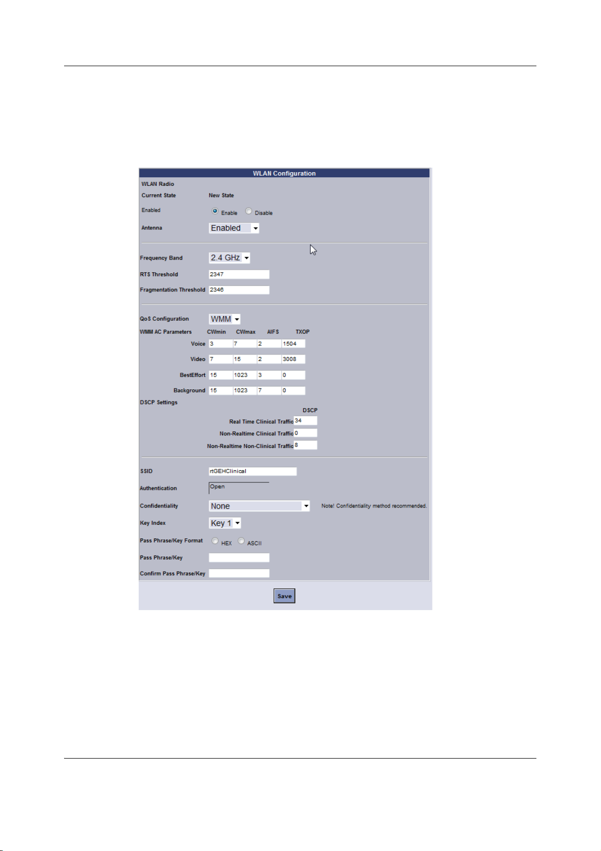
CARESCAPE Monitor B650
NOTE: Antenna diversity is a method used to assist in compensating for multipath interference.
When set to Enabled, Antenna Diversity monitors the signal from each antenna and
automatically switches to the one with the better signal.
5. Configure the appropriate WLAN settings. Note that the configurable attributes and
available values are different for MC Network and S/5 Network.
72
2081903-001
Page 86

WLAN Client Configuration
Configuration
Item Description
Frequency Band Select the frequency band to be
used with the WLAN radio:
-2.4 GHzPass
-5.1 GHz
- All Band (2.4 GHz & 5.1 GHz)
RTS Threshold Configure the RTS Threshold value. Use the default RTS Threshold value, unless
Fragmentation
Threshold
Configure the Fragmentation
Threshold value.
The WLAN radio is capable to communicate on
the following frequency bands, protocols and
data rates:
- 2.4 GHz, IEEE 802.11b, up to 11 Mbps.
- 2.4 GHz, IEEE 802.11g, up to 54 Mbps.
- 5.1 GHz, IEEE 802.11a, up to 54 Mbps.
NOTE: In the S/5 Wireless Network, the
frequency band is fixed to 2.4 GHz and it
supports 802.11b protocol only.
otherwise specified in the wireless network
design.
A valid RTS Threshold is a numeric value within
the range of 0 to 2347.
NOTE: This option is not configurable in the S/5
Wireless Network.
Fragmentation Threshold specifies the
maximum frame size a wireless device can
transmit without fragmenting the frame.
A valid Fragmentation Threshold is a numeric
value within the range of 256 to 2346.
Use the default Fragmentation Threshold value,
unless otherwise specified in the wireless
network design.
NOTE: This option is not configurable in the S/5
Wireless Network.
Comments
QoS Configuration
Select the Quality of Service (QoS)
standard used in the wireless
infrastructure to prioritize the
network traffic:
- None (no QoS in use)
- WMM (WLAN Multimedia in use)
Select QoS configuration setting as specified in
the wireless network design.
NOTE: This option is not configurable in S/5
Wireless Network.
73
2081903-001
Page 87

CARESCAPE Monitor B650
WLAN Client Configuration
Item Description
WMM AC Parameters
Configure the WMM AC Parameters
(CWmin, CWmax, AIFS, TXOP) for
each access category (voice, video,
best effort and background) if the
QoS Configuration was selected as
WMM.
Comments
WLAN Multimedia (WMM) provide basic Quality
of Service (QoS) features to IEEE802.11 networks
by prioritizing wireless network traffic according
to four Access Categories (AC) – voice, video,
best effort and background.
Use the default WMM AC parameter values,
unless otherwise specified in the wireless
network design.
Valid values:
- CWmin: 3-1023
- CWmax: 7-1023
-AIFS: 0-20
- TXOP: 0-65536 (0 for Best Effort and
Background)
NOTE: The WMM AC parameters are
configurable only if the QoS Selection was
selected as WMM.
NOTE: The DSCP settings are configurable only if
the QoS Selection was selected as WMM.
NOTE: This option is not configurable in S/5
Wireless Network.
Wireless DSCP
Settings
Configure the DSCP settings for the
following network traffic:
- Real Time Clinical Traffic
- Non-Real time Clinical Traffic
- Non-Real-time Non-Clinical
Traffic
Valid DSCP ranges:
Real Time Clinical Data 32 - 47
(Waveforms, Parameters, etc.)
Non-Real time Clinical Data 0 - 7
(Trends, Full Disclosure, Printing, etc.)
Non-Real-time Non-Clinical Data 8 - 23
(InSite, Service traffic, etc.)
DSCP (Differentiated Services Code Point)
settings provide Quality of Service (QoS) features
by prioritizing network traffic by traffic type. It
uses traffic classification by placing each data
packet into a limited number of traffic classes.
Use the default DSCP values, unless otherwise
specified in the wireless network design.
Note: For Non Real-Time Clinical Data traffic on
wireless, do not use DSCP values of 24-31. A risk
exists that Real-Time Clinical Data and Non
Real-Time Clinical Data will arrive at the same
QoS value in the wired network if proper DSCP to
DSCP mapping is not done at the wired to
wireless interface.
NOTE: This option is not configurable in the S/5
Wireless Network.
74
2081903-001
Page 88

WLAN Client Configuration
Configuration
Item Description
SSID Enter the Service Set Identifier (SSID),
also known as network name.
Confidentiality Select the Confidentiality (Data
Privacy) method to be used:
-None
- WEP (64-bit)
- WEP (128-bit)
- WPA-PSK (TKIP)
- WPA2-PSK (AES-CCMP)
Key Index Select the Key Index to be used. The Key Index of the wireless client must match
The SSID of the wireless client must match the
SSID of the wireless infrastructure.
A valid SSID includes up to 32 case-sensitive
ASCII characters, including space (ASCII decimal
32 to 126).
The confidentiality method of the wireless client
must match the confidentiality method of the
wireless infrastructure.
NOTE: The authentication method used with
WEP is Open System Authentication.
NOTE: The wireless MC Network supports only
confidentiality methods “None”, “WEP (128-bit)”,
"WPA-PSK (TKIP)" and "WPA2-PSK (AES-CCMP)"
NOTE: The S/5 Wireless Network supports only
confidentiality methods “None”, "WEP (64-bit)
and “WEP (128-bit)”.
the Key Index of the wireless infrastructure.
NOTE: The Key Index is selectable only if the
confidentiality method selected is “WEP (64-bit)”
or “WEP (128 bit)”.
Comments
Pass Phrase / Key
Format
Select the Pass Phrase / Key Format:
-ASCII
-HEX
Select the format of entering a Pass Phrase /
Key Format.
75
2081903-001
Page 89

CARESCAPE Monitor B650
WLAN Client Configuration
Item Description
Pass Phrase / Key Enter the Pass Phrase / Key for the
used confidentiality method as an
ASCII or HEX string as selected
above:
WEP (64-bit) / WEP (128-bit):
- Enter a 5/13 character long ASCII
string. The system will generate a
10/26 character hexadecimal
security key and assign it to the
currently selected Key Index.
OR
- Enter a 10/26 character long
hexadecimal (HEX) string. This
security key will be assigned for
the currently selected Key Index.
WPA-PSK (TKIP) and
WPA2-PSK (AES-CCMP)
- Enter a 8 to 63 character long
(ASCII) string
OR
- Enter a 64 character long
hexadecimal (HEX) string
Comments
The Pass Phrase / Key of the wireless client must
match the Pass Phrase / Key of the wireless
infrastructure.
A valid ASCII Pass Phrase / Key includes only
printable ASCII characters, that is space and
ASCII decimals 32 to 126. However the following
ASCII decimals are not valid: 34 (" ), 36 ($ ), 39 (' ),
92 (\ ), and 96 (` ).
A valid HEX Pass Phrase / Key may include
numeric characters 0-9 and alpha characters
A-F.
NOTE: A Pass Phrase / Key will be displayed as
10 successive asterisk (*) characters, after it has
been saved.
Confirm Pass Phrase
/ Key
6. Select Save to confirm the selections above.
If the WLAN Radio status is changed, all the WLAN configuration changes take effect on the
next monitor restart. If the WLAN Radio status is not changed, all the WLAN configuration
changes will take effect immediately.
Re-enter the Pass Phrase / Key
entered above.
7.3 Setting time and date
NOTE: In the S/5 Network, the patient monitor’s date and time is automatically synchronized
with the date and time of the iCentral it is connected to. You can set the date and time locally
only if the patient monitor is not connected to the S/5 Network and the patient monitor is in a
discharged state.
CAUTION NETWORK DEVICE TIME SYNCHRONIZATION — When adding a new device to
the CARESCAPE Network, the existing devices on the CARESCAPE Network will
synchronize to the new device’s time. To prevent potential time
synchronization issues, you should set the new device’s time to be as close as
possible to the time (within one minute or less) used by the existing GE devices
on the CARESCAPE Network.
1. Log in to Webmin.
2. Select Configuration > Time.
76
2081903-001
Page 90

3. In the Time Configuration window, in Configure Date and Time, update the following
fields as needed:
•Date
•Month
• Year
• Hour:Minute
•AM/PM
• 12/24 Hrs
4. Select Save.
The manual time configuration takes effect immediately.
7.4 Setting unit and bed name
Configure the care unit name and bed name for patient monitors that are configured to
connect to the MC Network.
NOTE: The unit name shall be set the same with all the patient monitors and CARESCAPE CIC
Pro central stations that are connected to the same care unit in the MC Network. Bed name
shall be unique to each patient monitor in the same care unit.
Configuration
NOTE: Unit and bed name selections are not available if network selection is S/5.
1. Log in to Webmin.
2. Select Configuration > Unit and Bed Name.
3. In the Unit and Bed Name Configuration window, view or set the unit name and bed
name for the device.
NOTE: Use only capital letters A - Z, numbers, dash (-), asterisk (*) and space ( ). The unit name
may be up to seven characters long and bed name up to five characters long.
4. Select Save.
The unit and bed name configuration takes effect immediately.
7.5 Configuring printers
You can configure the patient monitor to print to up to 12 laser printers connected on the IX
Network. Use the Webmin sub-modules to install or delete a printer and to print a test page.
NOTE: Ensure that you have the host name(s) or IP address(es) for all the connected IX printers
available. Configure the IX printers according to this information.
NOTE: Laser printers that are installed on central stations do not need to be configured using
Webmin. Refer to the user’s manual for details on configuring the printer.
NOTE: This Webmin module is available only if the monitor is equipped with the Advanced
Interface Board that provides both the MC and the IX Network interfaces.
NOTE: Refer to the CARESCAPE Modular Monitors Supplemental Information Manual for the list
of supported devices.
7.5.1 Installing a printer
1. Log in to Webmin.
2. Select Configuration > Printers.
3. In the Sub-Modules for Printers menu, select Install Printer.
77
2081903-001
Page 91

CARESCAPE Monitor B650
4. Below Printer Configuration Information in the Install Printer window, provide the
following information:
a. Select either the Hostname or IP Address radio button, as applicable.
b. In the Hostname or IP Address field, enter the printer Hostname or IP Address.
c. In the Printer Name field, enter the Printer Name.
d. Select Yes from the drop down list next to Test Page.
5. Select Save.
6. From the patient monitor, select Monitor Setup > Printing.
7. Select the Devices > Setup.
8. In the Printout menu, select what to print out (for example, Waveforms, Alarm
Waveforms, Numeric Trends, Reports).
9. Below Location, select the radio button next to Network.
10. From the drop down list next to Network Device, select the desired printer.
The change will take effect immediately.
7.5.2 Deleting a printer
NOTE: Before deleting a laser printer, check Monitor Setup > Printing > Devices > Status. If a
printout is assigned to the printer to be deleted, redirect the printout to another valid printer.
1. Log in to Webmin.
2. Select Configuration > Printers.
3. In the Sub-Modules for Printers menu, select Delete Printer.
4. In the Delete Printer window, select the printer to delete.
5. Select Save.
The change will take effect immediately.
7.5.3 Printing a test page
1. Log in to Webmin.
2. Select Configuration > Printers.
3. In the Sub-Modules for Printers menu, select Print Test Page.
4. In the Print Test Page window, select the printer.
5. Select Save.
7.6 Configuring MUSE/12SL
NOTE: MUSE viewing and the related configuration settings are available only if the monitor is
equipped with the Advanced Interface Board that provides both the MC and the IX Network
interfaces.
NOTE: MUSE viewing is a licensed software feature. You can configure the MUSE/12SL settings
independent of the license status, but actual viewing of MUSE reports requires that the
MuseView license is enabled.
Settings to send 12SL data
1. Log in to Webmin.
2. Select Configuration > MUSE/12SL.
3. In the MUSE/12SL window, enter the applicable information in the following fields:
78
2081903-001
Page 92

- Location ID Identifies the location ID number (within the range 0 to 599)
associated with the patient monitor for searching the MUSE
system.
- Site Number Identifies the site number (within the range 1 to 254) associated
with the patient monitor for searching the MUSE system.
4. Select Save.
These settings take effect immediately after they are submitted.
Settings to view 12SL data
1. Log in to Webmin.
2. Select Configuration > MUSE/12SL.
3. In the MUSE/12SL window, enter the following:
- MUSE Web Username Username used to authenticate with the MUSE
Web to access 12-lead reports.
- MUSE Web Password Password used to authenticate with the MUSE
Web to access 12-lead reports.
-Confirm Password The password and the confirmed password must
be the same.
Configuration
- MUSE Web URL Used to locate the MUSE Web system to access
4. Select Save.
These settings take effect immediately after they are submitted.
7.7 Admit settings
7.7.1 Patient ID prefix
The patient monitor will automatically generate a temporary, unique patient ID when a patient
with unknown ID is admitted to the patient monitor. The patient monitor will use this temporary
patient ID for all 12SL reports that are sent to MUSE until the patient is discharged from the
patient monitor, or his/her patient ID is changed. The temporary patient ID is generated from
the temporary patient ID prefix, care unit name, bed name, and current time.
The temporary patient ID prefix is a hospital defined prefix that is used as the first two
characters in a temporary patient ID to ensure its uniqueness inside the hospital.
1. Log in to Webmin.
2. Select Configuration > Admit Settings.
3. In the Sub-Modules for Admit Settings menu, select Patient ID Prefix.
4. In the Patient ID Prefix window, enter a 2-character prefix.
NOTE: Valid values are uppercase letters and numbers.
5. Select Save.
All changes take effect immediately.
12-lead reports. Enter the URL in a valid format.
79
2081903-001
Page 93

CARESCAPE Monitor B650
7.7.2 Barcode settings
Barcode settings must be configured if a barcode reader is used to input patient data to the
Admit/Discharge menu.
NOTE: Acquire detailed specification of the character-delimited or the length-delimited,
multi-field barcode that the hospital uses. This will configure the barcode parser correctly.
NOTE: Acquire sample barcodes, if possible, to verify the operation of the parser configuration.
NOTE: For details on barcode data requirements and restrictions, see section 7.7.5 Barcode
data specifications.
1. Select the parser type.
a. Log in to Webmin.
b. Select Configuration > Admit Settings.
c. In the Sub-Modules for Admit Settings window, select Barcode Settings.
d. Below Barcode Setup in the Barcode Settings window, select the applicable parser
type from the drop-down list:.
Parser type Used with this type of barcode
No Parser Simple barcode that contains one piece of
information, but no data control, so there is no
need for a parser.
Length Delimited Parser Barcode that specifies the beginning position and
length of each field on the barcode.
Character Delimited Parser Barcode that specifies a special character that
separates each field on the barcode.
2. Select Save.
If you selected No Parser, the barcode setting configuration is complete.
For a Length or Character Delimited Parser, follow the applicable instructions.
− 7.7.3 Configuring Length Delimited Parser information.
or
− 7.7.4 Configure character delimited parser information.
7.7.3 Configuring Length Delimited Parser information
Points to note
− If you configure Age, you must either select the Age Unit item or one of the age units (e.g.,
Years, Months, Weeks, Days) below Fixed Option.
− If you configure Height, you must either select the Height Unit item or one of the height
units (e.g., Feet, Inches, Meters, Centimeters, Millimeters) below Fixed Option.
− If you configure Weight, you must either select the Weight Unit item or one of the weight
units (e.g., Kilograms, Grams, Micrograms, Pounds, Ounces) below Fixed Option.
− For an example of admit/discharge configuration for a length delimited parser, see
Example of Length Delimited Parser information on page 81.
1. In the Admit/Discharge Configuration window, enter the location and length information
for each data item.
If an item is not included in the barcode, type 0 in the item’s Position and Length fields, or
leave the Position and Length fields blank.
80
2081903-001
Page 94

a. In the Position column, type the beginning position of the field in the data string
(from 1 to 300).
b. In the Length column, type the number of characters (from 1 to 99) that the field
contains.
2. For Gender Format, select Fixed or Configured.
If you select Configured:
a. Type the character that identifies Male.
b. Type the character that identifies Female.
3. Below Fixed Option, select the applicable value:
Configuration
Item Item selection in the top part of
Fixed Option selection
the screen
Height Unit Both Height and Height Unit Non-Fixed.
Height only Select value from drop down list.
Weight Unit Both Weight and Weight Unit Non-Fixed.
Weight only Select value from drop down list.
Age Unit Both Age and Age Unit Non-Fixed.
Age only Select value from drop down list.
4. Scroll to the bottom of the window, and select Save.
All changes take effect immediately.
Example of Length Delimited Parser information
In this example, the barcode contains 10 items. The following table lists the starting position
and length of each item.
Item Starting Position Length
MRN
First Name
Last Name
110
11 10
21 15
Day of Birth
Month of Birth
Year of Birth
Age
Age Unit
Gender
Height
The following sample shows the corresponding entries in the Admit/Discharge Configuration
window.
46 2
48 2
50 4
36 5
41 5
54 1
55 5
81
2081903-001
Page 95
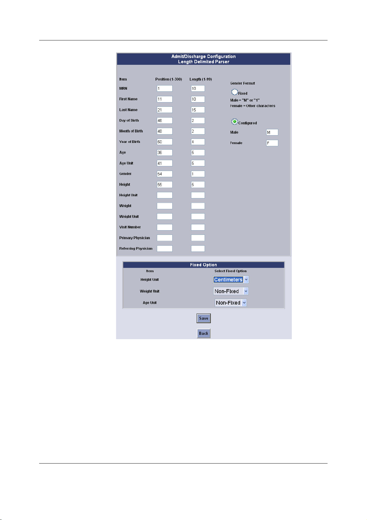
CARESCAPE Monitor B650
7.7.4 Configure character delimited parser information
Points to note
− If you configure Age, you must either select the Age Unit item or one of the age units (e.g.,
Years, Months, Weeks, Days) below Fixed Option.
− If you configure Height, you must either select the Height Unit item or one of the height
units (e.g., Feet, Inches, Meters, Centimeters, Millimeters) below Fixed Option.
− If you configure Weight, you must either select the Weight Unit item or one of the weight
units (e.g., Kilograms, Grams, Micrograms, Pounds, Ounces) below Fixed Option.
− For an example of admit/discharge configuration for a length delimited parser, see
Example of character delimited parser information entry on page 83.
82
2081903-001
Page 96

Configuration
1. In the Position column of the Admit/Discharge Configuration window, enter the
sequence number of each item included in the barcode. Use incremental numbers from 1
(the left-most field) up to 16 (the right-most field).
If an item is not included in the barcode, leave the Position field blank for the item.
2. Below Field Delimiter, in the Delimiter field, enter the special character that separates
the fields on the barcode.
NOTE: Allowed characters are ASCII characters 33-126.
NOTE: Forbidden characters are control characters (ASCII characters 0-31), the space
character (ASCII character 32), and ASCII characters 127 and above.
NOTE: If the character selected exists in any field in the barcode, it will be misinterpreted as a
field delimiter.
3. Below Gender Code, enter the codes that identify Male and Female.
4. Below Fixed Option, select the applicable value:
Item Item selection in the top
Fixed Option selection
part of the screen
Height Unit Both Height and Height Unit Non-Fixed.
Height only Select value from drop down list.
Weight Unit Both Weight and Weight Unit Non-Fixed.
Weight only Select value from drop down list.
Age Unit Both Age and Age Unit Non-Fixed.
Age only Select value from drop down list.
5. Scroll to the bottom of the window, and select Save.
All changes take effect immediately.
Example of character delimited parser information entry
In the following example, the barcode contains 12 items and uses the pound sign (#) as a
delimiter.
Item Sequence number of the item in the
barcode
MRN
First Name
4
5
Last Name
Day of Birth
Month of Birth
Year of Birth
Age
Age Unit
Gender
6
1
2
3
11
12
7
83
2081903-001
Page 97
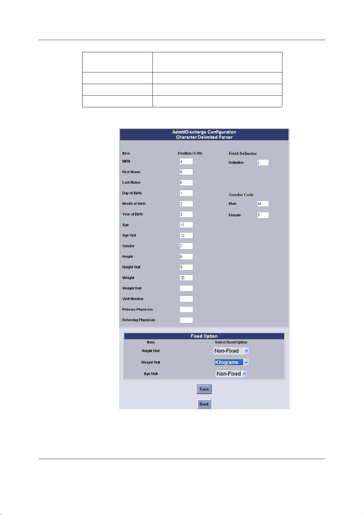
CARESCAPE Monitor B650
Item Sequence number of the item in the
barcode
Height
Height Unit
Weight
The following sample shows the corresponding entries in the Admit/Discharge Configuration
window.
8
9
10
7.7.5 Barcode data specifications
Points to note
− The maximum length of the entire barcode is 300.
84
2081903-001
Page 98

Configuration
− If the field value is longer than the maximum length indicated, the right-most characters
will be truncated when the value is displayed in the Admit/Discharge menu.
If a field contains a forbidden character, that character will be replaced with a space
when it is displayed in the Admit/Discharge menu.
Item
MRN 99 Both letters and numbers Forbidden characters are those that are not
First Name 99
Last Name 99
Day of Birth 2 1-31 If Day of Birth is present in the barcode, then
Month of Birth 2 1-12 If Month of Birth is present in the barcode,
Year of Birth 4 1880 to current year If Year of Birth is present in the barcode, then
Age 99 Numeric 9999.9999 Either a period or comma is accepted as a
Age Unit 99 A, Y, YR, YRS (years)
Maximum
length
Valid entries Comments
allowed by the patient monitor, including the
following characters:
! " # ¤ % & /( ) = ? ` @ £ $ € { [ ] } \ * ^ _ : ; | < >
Month of Birth and Year of Birth also need to
be present.
then Day of Birth and Year of Birth also need
to be present.
Day of Birth and Month of Birth also need to
be present.
decimal symbol.
MO, MOS (months)
WK, WKS (weeks)
D, DAY, DYS (days)
Gender 1 If gender is configured (not fixed), this must
be 1 character.
Height 99 Numeric 9999.9999 Either a period or comma is accepted as a
decimal symbol.
Height Unit 99 FT (feet)
IN (inches)
M (meters)
CM (centimeters)
MM (millimeters)
Weight 99 Numeric 9999.9999 Either a period or comma is accepted as a
decimal symbol.
Weight Unit 99 KG, KGS (kilograms)
G, GM, GMS (grams)
MCG (micrograms)
OZ, OZS (ounces)
LB, LBS (pounds)
Visit Number 99 Both letters and numbers Forbidden characters are those that are not
Primary Physician 99
Referring Physician 99
allowed by the patient monitor, including the
following characters:
! " # ¤ % & /( ) = ? ` @ £ $ € { [ ] } \ * ^ _ : ; | < >
85
2081903-001
Page 99

CARESCAPE Monitor B650
7.8 Setting power frequency
WARNING Incorrect power line frequency setting could adversely affect ECG and EEG
processing.
1. Log in to Webmin.
2. Select Configuration > Power Frequency.
3. In the Power Frequency window, select the applicable power line frequency.
4. Select Save.
The power frequency configuration takes effect immediately.
7.9 Selecting language and locale
Select the language used in clinical user interface and select the keyboard locale setting for the
alphanumeric keyboard and the barcode reader.
1. Log in to Webmin.
2. Select Configuration >Language.
3. In the Language window, select the patient monitor language and keyboard language:
a. Select the patient monitor language from the drop-down list and select Save.
b. Select the keyboard locale from the drop-down list and select Save.
The language takes effect after the patient monitor is restarted. The keyboard locale takes
effect immediately after it is submitted.
7.10 Selecting national requirements
Activate France specific defaults for the ECG HR adjustment range and the reminder beep
behavior.
1. Log in to Webmin.
2. Select Configuration > National Requirements.
3. In the National Requirement window, select the applicable option:
Value Description
None Select the normal defaults.
France Enable the following country specific monitoring:
- Heart Rate high alarm limit maximum 230.
- Reminder beep will sound every 2 minutes when alarms have
been silenced permanently.
4. Select Save.
The national requirements changes take effect immediately.
7.11 Configuring modules
You can configure some acquisition module specific settings. The settings are saved to the
permanent memory of the related acquisition module and the settings travel with the module
from one patient monitor to another.
These settings are pre-configured at factory, except the Assets Settings. You may need to
re-configure them after corrective maintenance, or for administration purposes.
86
2081903-001
Page 100

Configuration
Refer to the Module Frames and Modules Technical Manual for detailed information on how to
change these settings.
Webmin
sub-module
Assets Settings PDM This setting allows you to view the customer
Licensing PDM This setting allows you to manage the PDM
ECG Filter
Configuration
STP/TP/ST Settings E-PRESTN, E-PRETN,
P/PT/PP Settings E-P, E-PT & E-PP This setting allows you to configure the
7.11.1 Module asset settings
NOTE: This configuration applies only to the PDM.
NOTE: The Device Serial Number field is view only and cannot be changed.
To set the device asset number of a PDM:
1. Log in to Webmin.
2. Select Configuration > Modules.
3. In the Sub-Modules for Modules menu, select Assets Settings.
4. In the Assets Settings window, enter the user-assigned asset number for the device in
the Change Value to column.
5. Select Save.
The change will take effect immediately.
Module Description
assigned asset number of the PDM.
feature licenses.
PDM This setting allows you to temporarily
disable the ECG filter of the PDM.
This setting allows you configure the
E-RESTN, E-PSM &
E-PSMP
STP/TP/ST setting after replacing the STP
board.
P/PT/PP setting after replacing the STP
board.
7.12 Setting the host asset number
Enter a host asset number and view the host serial number.
NOTE: The Host Serial Number field is view only and cannot be changed.
To set the host asset number:
1. Log in to Webmin.
2. Select Configuration > Host Asset Settings.
3. In the Host Asset Settings window, enter the user-assigned host asset number (up to 32
ASCII characters long) in the Change Value to column.
4. Select Save.
The host asset changes take effect immediately.
7.13 Changing passwords
You can change the passwords for the biomed and clinical users.
87
2081903-001
 Loading...