

Page 1
GE Healthcare
B30 Patient Monitor
User's Guide
English
2039822-002 A (paper)
© 2009 General Electric Company.
All rights reserved.
Page 2

Page 3

B30 Patient Monitor
User's Guide
Related to software L-DICU08
0459
All specifications are subject to change without notice.
Document no. 2039822-002 A
9th January 2009
GE Medical Systems Information Technologies, Inc.
8200 West Tower Avenue
Milwaukee, WI USA
Zip: 53223
Tel: 1 414 355 5000 (outside US)
800 558 5102 (US only)
Fax: 1 414 355 3790
www.gehealthcare.com
Copyright © 2009 General Electric Company. All rights reserved.
GE Healthcare
3F Building 1, GE Technology Park
1 Huatuo Road
Shanghai PRC 201203
Tel: +86 21 3877 7888
Fax: +86 21 3877 7451
Page 4

About this guide
This User's Guide describes the features and functions offered by the
B30 monitor. Descriptions refer to the software L-DICU08.
This manual is an integral part of the product and describes its
intended use. Keep it always close to the equipment. Observance of
the manual is a prerequisite for proper product performance and
correct operation and ensures patient and operator safety.
If you are a new user of the monitor, we suggest you begin with
sections "Safety precautions", "System introduction" and "Monitoring
basics." The following conventions are used:
− Names of the hard keys on the Command Board and modules
are written in the following way:
ECG.
− Menu items are written in bold italic typeface: ECG Setup.
− Menu access is described from top to bottom. For example, the
selection of the Screen Setup menu item and the Waveform
Fields menu item would be shown as Screen Setup - Waveform
Fields.
− Messages (alarm messages, informative messages) displayed on
the screen are written inside single quotes: 'Learning.'
− When referring to different sections in this manual, section
names are enclosed in double quotes: "Cleaning and care."
− In this manual, the word "select" means choosing and
confirming.
Related documentation
−
Clinical aspects, basic methods of measurement and technical
background: B30 Patient Monitor User's Reference Manual
− Installation, technical solutions and servicing: B30 Patient
Monitor Technical Reference Manual
− Options and selections of the software: B30 Patient Monitor
Default Configuration Worksheet
− Compatible supplies and accessories: B30 Patient Monitor
Supplies and Accessories
− Other devices closely related to the monitor: iCentral User's
Reference Manual
Trademarks
Dash, Datex, Ohmeda, S/5, D-fend, D-fend+, Mini D-fend, OxyTip+,
ComBar, ComWheel, EarSat, FingerSat, FlexSat are trademarks of GE
Healthcare. All other product and company names are property of
their respective owners.
Product availability
Some of the products mentioned in this manual may not be
available in all countries. Please, consult your local representative
for the availability.
Service Lifetime
The Service lifetime of this patient monitor is 5 years. At the end of its
service lifetime, the product described in this manual, as well as its
accessories, must be disposed of in compliance with the guidelines
regulating the disposal of such products. If you have questions
concerning disposal of the product, please contact GE
representatives.
Page 5

Intended purpose (Indications for use)
The B30 patient monitor is intended for multiparameter patient
monitoring. The B30 monitor is indicated for continuous monitoring
of hemodynamic parameters (including arrhythmia and ST segment
analysis) and respiratory status and creation of limit alarms.
The B30 monitor is intended for all hospital patients and all hospital
departments including intra-hospital transport but excluding harsh
physical environment like MRI.
The Patient side module E-PSM(P)W and accessories are indicated
for monitoring of hemodynamic parameters of all hospital patients.
The hemodynamic parameters of the module comprise ECG
(including ST-Segment and arrhythmia), impedance respiration,
oscillometric NIBP (sys/dia/mean), temperature, SpO
monitoring during conditions of clinical patient motion), and invasive
blood pressure. Impedance respiration measurement is indicated for
patients ages three years and up. The NIBP measurement is
indicated for patients who weight 5kg (11 lb) or up.The E-PSM(P)W is
intended for all hospital departments including intra-hospital
transport but excluding harsh physical environment like MRI.
The extension module N-FCREC (option N-FCREC or N-FC) is
indicated for monitoring of CO
patients. CO2 measurements are indicated for patients who weight
over 5 kg (11 lb).
The B30 monitor and N-F(C)(REC) Extension Module and E-PSM(P)W
Patient Side Module are indicated for use by qualified medical
personnel only.
and respiration rate of all hospital
2
(including
2
Classifications
In accordance with IEC 60601-1:
−
Class I and internally powered equipment - the type of
protection against electric shock.
− Type BF or CF equipment. The degree of protection against
electric shock is indicated by a symbol on each parameter
module.
− Equipment is not suitable for use in the presence of a flammable
anesthetic mixture with air or with oxygen or nitrous oxide.
− Continuous operation according to the mode of operation.
− Portable Monitor
In accordance with IEC 60529:
−
IPX1 - degree of protection against harmful ingress of water.
In accordance with EU Medical Device Directive: IIb
In accordance with CISPR 11:
Group 1 Class B; see page 3 of this User's Guide.
Responsibility of the manufacturer
GE Medical Systems Information Technologies, Inc. is responsible for
the safety, reliability and performance of the equipment only if:
− Assembly, extensions, readjustments, modifications, service and
repairs are carried out by personnel authorized by GE.
− Electrical installation complies with appropriate requirements.
− The equipment is used in accordance with this User's Guide.
Page 6

Contents
Safety precautions . . . . . . . . . . . . . . . . . . . . . . . . . . . . . 1
Symbols . . . . . . . . . . . . . . . . . . . . . . . . . . . . . . . . . . . . . . . 5
System introduction . . . . . . . . . . . . . . . . . . . . . . . . . . . . 9
Monitor introduction . . . . . . . . . . . . . . . . . . . . . . . . . .11
Monitoring basics . . . . . . . . . . . . . . . . . . . . . . . . . . . . .23
Setting up the monitor before use . . . . . . . . . . . . . .25
Entering and loading patient data . . . . . . . . . . . . .31
Starting and ending . . . . . . . . . . . . . . . . . . . . . . . . . . .33
Screen setup . . . . . . . . . . . . . . . . . . . . . . . . . . . . . . . . . .35
Alarms . . . . . . . . . . . . . . . . . . . . . . . . . . . . . . . . . . . . . . . .37
Printing and recording . . . . . . . . . . . . . . . . . . . . . . . . .41
Trends . . . . . . . . . . . . . . . . . . . . . . . . . . . . . . . . . . . . . . . .45
Cleaning and care . . . . . . . . . . . . . . . . . . . . . . . . . . . . .47
ECG and ST . . . . . . . . . . . . . . . . . . . . . . . . . . . . . . . . . . .53
Pulse oximetry . . . . . . . . . . . . . . . . . . . . . . . . . . . . . . . .63
Non-invasive blood pressure (NIBP) . . . . . . . . . . . .67
Invasive blood pressure . . . . . . . . . . . . . . . . . . . . . . .71
Airway gas (CO2) . . . . . . . . . . . . . . . . . . . . . . . . . . . . . .75
Troubleshooting . . . . . . . . . . . . . . . . . . . . . . . . . . . . . . .79
Messages . . . . . . . . . . . . . . . . . . . . . . . . . . . . . . . . . . . . .81
Abbreviations . . . . . . . . . . . . . . . . . . . . . . . . . . . . . . . . .85
Performance . . . . . . . . . . . . . . . . . . . . . . . . . . . . . . . . . .91
ElectroMagnetic Compatibility . . . . . . . . . . . . . . . . .97
End User License Agreement . . . . . . . . . . . . . . . . 105
Warranty . . . . . . . . . . . . . . . . . . . . . . . . . . . . . . . . . . . 107
Impedance respiration . . . . . . . . . . . . . . . . . . . . . . . .59
Temperature . . . . . . . . . . . . . . . . . . . . . . . . . . . . . . . . . .61
i
Page 7

1
Safety precautions
These precautions refer to the entire system. Warnings and cautions specific to parts of the system can be found in the relevant section.
Warnings
A WARNING indicates a situation in which the user or
the patient may be in danger of injury or death.
• Connect only one patient to the monitor at a time.
• Do not use the monitor without manufacturer approved
mounting attached.
• Use only hospital-grade grounded power outlets and power
cord.
• To avoid the risk of electric shock, this equipment must only be
connected to a supply mains with protective earth.
• Do not use an additional multiple socket outlet or extension cord.
• After transferring or reinstalling the monitor, always check that it
is properly connected and all parts are securely attached. Pay
special attention to this in case of stacked mounting.
• If you accidentally drop the monitor or modules, have them
checked by authorized service personnel prior to clinical use.
• Vibrations during intrahospital transport may disturb SpO
impedance respiration, NIBP and InvBP measurements.
• Some equipment malfunctions may not generate a monitor
alarm. Always keep the patient under close surveillance.
• To avoid explosion hazard, do not use the monitor in presence of
flammable anesthetics.
• Do not use the monitor in high electromagnetic fields (for
example, during MRI.)
• Do not connect any external devices to the system other than
those specified.
, ECG,
2
• Do not touch the patient, table, instruments, modules or the
monitor during defibrillation.
• If the integrity of the external protective earth conductor
arrangement is in doubt, use the monitor with battery operation.
• When detaching modules, be careful not to drop them. Always
support with one hand while pulling out with the other.
• Use only approved accessories, batteries, mounts and
defibrillator-proof cables and invasive pressure transducers. For
a list of approved supplies and accessories, see the "Supplies
and Accessories" catalog delivered with the monitor. Other
cables, batteries, transducers and accessories may cause a
safety hazard, damage the equipment or the system, result in
increased emissions or decreased immunity of the equipment or
system or interfere with the measurement. Protection against
cardiac defibrillator discharge is due in part to the accessories
for pulse oximetry (SpO
(P) measurement.
• Single-use accessories are not designed to be re-used. Re-use
may cause a risk of contamination and affect the measurement
accuracy.
• Do not incinerate a battery or store at high temperatures, as it
will explode.
• The monitor or its components should not be used adjacent to or
stacked with other equipment. If adjacent or stacked use is
necessary, the monitor and its components should be observed
to verify normal operation in the configuration in which it will be
used.
• Connecting electrical equipment together or using the same
extension cord for more than one device may cause their
leakage currents to exceed the limits specified in relevant safety
), temperature (T) and invasive pressure
2
Page 8

standards. Always make sure that the combination complies
with the international safety standard IEC 60601-1-1 for medical
electrical systems and with the requirements of local authorities.
• Pins of connectors identified with the ESD warning symbol
should not be touched. Connections should not be made to
these connectors unless ESD precautionary procedures are
used. See "Safety precautions: ESD precautionary procedures" in
the"User's Reference Manual" for details.
• Other equipment may interfere with the system, even if that
other equipment complies with CISPR emission requirements.
• If liquid has accidentally entered the system or its parts,
disconnect the power cord from the power supply and have the
equipment serviced by authorized service personnel.
• If the unit fails to respond as described, do not use the monitor
until tested and repaired by authorized service personnel.
• The system is intended for use by qualified medical personnel
only.
• Before cleaning, disconnect the monitor from the power supply.
• Use only an intact power cord. Replace the power cord if it is
cracked, frayed, broken or otherwise damaged.
• Do not apply tension to the power cord otherwise the cord may
get damaged.
• The power cord may only be connected to a three-wire,
grounded, hospital grade receptacle.
• NOTE: The monitor is always internally powered when the
batteries are connected.
• The B30 is always energized by the internal batteries. A short
circuit may cause internal damage. Do not touch any exposed
wiring or conductive surface inside, this may cause an electric
shock.
• Make sure that the Pole Mount for PSMW is always used in
vertical position to prevent water from entering the E-PSM(P)W
module.
Cautions
A CAUTION indicates a situation in which the unit or
devices connected to it may be damaged.
• Before connecting the power cord to the power supply, check
that the local voltage and frequency correspond with the rating
stated on the device plate.
• Leave space for circulation of air to prevent the monitor from
overheating.
• Refresh the batteries completely every six months (see "Cleaning
and care").
• Do not store or use the monitor outside the temperature and
humidity ranges specified in the "Performance" section of this
manual.
• After replacing a battery, always make sure that you close the
battery compartment by sliding the lid back to the right until it
clicks.
• Perform regular functional testing of each of the parameters and
accessories
• The monitor display is fragile. Ensure that it is not placed near a
heat source or exposed to mechanical shocks, pressure,
moisture or direct sunlight.
• Do not immerse any part of the device in liquids or allow liquid to
enter the interior.
• Do not autoclave any part of the system with steam or sterilize
with ethylene oxide.
• Do not apply pressurized air to any outlet or tubing connected to
the monitor. Pressure may destroy sensitive elements.
• Before use, allow two minutes for warm-up and note any error
messages or deviations from normal operation.
• Do not short-circuit the battery terminals, this may produce a
very high current, which will damage the battery.
2
Page 9

3
• Do not store or transport the monitor outside the specified
temperature, pressure and humidity ranges.
Disposal
•Dispose of the whole device, parts of it, its packing material and
this manual in accordance with local environmental and waste
disposal regulations.
Points to note
• This manual is intended for clinical professionals. Clinical
professionals are expected to have a working knowledge of
medical procedures, practices, and terminology, as required for
monitoring of critically ill patients.
• Medical electrical equipment needs special precautions
regarding electromagnetic compatibility and needs to be
installed and put into service according to the electromagnetic
compatibility information provided in the "Technical Reference
Manual" by qualified personnel.
• Portable and mobile RF communications equipment can affect
the medical electrical equipment.
• The allowed cables, transducers, accessories and mounts for the
system are listed in the "Supplies and Accessories" catalog.
• The equipment is suitable for use in the presence of
electrosurgery. Please notice the possible limitations in the
parameter sections and in the "Performance" section.
• Service and repairs are allowed for authorized service personnel
only.
• CISPR 11 classification: Group 1, Class B:
− Group 1 contains all ISM (Industrial, scientific and medical)
equipment in which there is intentionally generated and/or
used conductively coupled radio-frequency energy which is
necessary for the internal functioning of the equipment itself.
− Class B equipment is suitable for use in domestic
establishments and in establishments directly connected to
a low voltage power supply network which supplies buildings
used for domestic purposes.
Page 10

For your notes:
4
Page 11
Symbols
5
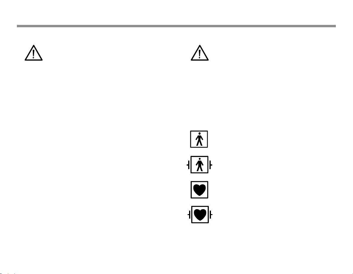
− Attention, consult accompanying documents.
− On the modules or frames indicates that
modules with identical measurements should
not be used in the same monitor. If such
modules have been inserted, remove the
module that has been most recently connected.
You can also remove both modules and reconnect the new module after five second.
− On the E-PSM(P)W module indicates that
protection against cardiac defibrillator
discharge is due in part to the accessories for
pulse oximetry (SpO2), temperature (T) and
invasive pressure (P) measurement.
− On the N-FC(REC) module indicates that airway
gases should be calibrated every six months in
normal use and every two months in continuous
use.
− On top of the monitor beside the battery cover:
Use manufacturer recommended batteries only.
Follow the regional regulations for disposal.
− On the rear panel this symbol indicates the
following warnings and cautions:
−Electric shock hazard. Do not open the cover or
the back. Refer servicing to qualified
personnel.
−For continued protection against fire hazard,
replace the fuse only with one of the same
type and rating.
−Disconnect from the power supply before
servicing.
−Do not touch the monitor during defibrillation.
−Do not use the monitor without manufacturer
approved mounting attached.
Type BF (IEC 60601-1) protection against electric
shock
Type BF (IEC 60601-1) defibrillator-proof protection
against electric shock
Type CF (IEC 60601-1) protection against electric
shock
Type CF (IEC 60601-1) defibrillator-proof protection
against electric shock
Page 12
When displayed in the upper left corner of the
screen, indicates that the alarms are silenced. When
displayed in the menu or digit fields, indicates that
the alarm source has been turned off or alarm does
not meet the alarm-specific activation criteria.
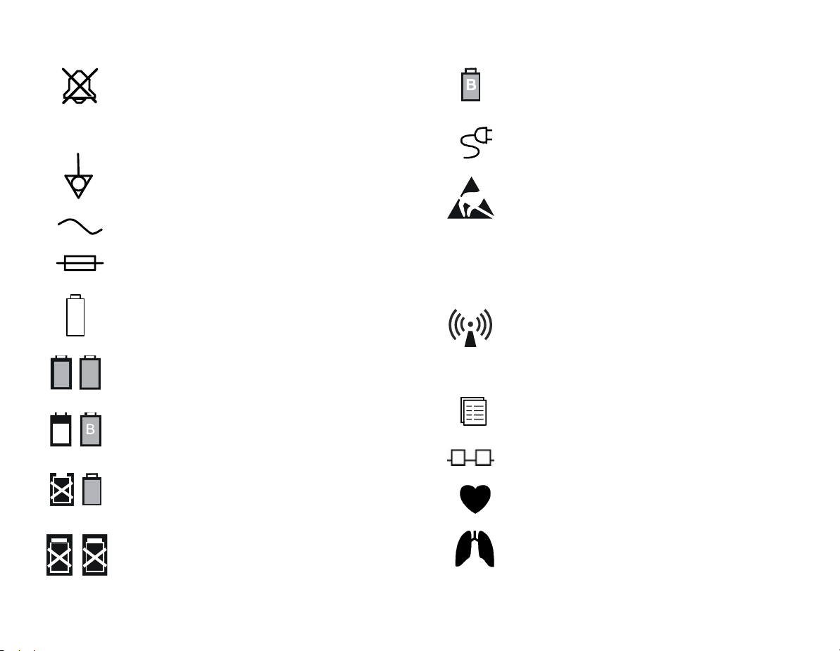
Equipotentiality. Monitor can be connected to
potential equalization conductor.
Alternating current
Fuse. Replace the fuse only with one of the same
type and rating.
In the front panel: battery.
B
A
B
Battery operation and remaining capacity. The
height of the green bar indicates the charging level.
Battery (A) charging (white bar)
SN,S/N Serial number
Battery (A) missing
In the front panel: mains/external DC power
ESD warning symbol for electrostatic sensitive
devices. Pins of connectors identified with the ESD
warning symbol should not be touched.
Connections should not be made to these
connectors unless ESD precautionary procedures
are used. See "Safety precautions: ESD
precautionary procedures" in the "User's Reference
Manual" for details.
Symbol for non-ionizing electromagnetic radiation.
Interference may occur in the vicinity of equipment
marked with this symbol.
Submenu. Selecting a menu item with this symbol
opens a new menu.
The monitor is connected to Network.
B
Battery (A) failure
Both batteries failed
A blinking heart next to the heart rate or pulse rate
value indicates the beats detected.
A lung next to the respiration rate value indicates
that respiration rate is calculated from the
impedance respiration measurement.
6
Page 13

Date of manufacture
This symbol indicates that the waste of electrical
and electronic equipment must not be disposed as
unsorted municipal waste and must be collected
separately. Please, contact an authorized
representative of the manufacturer for information
concerning the decommissioning of your
equipment.
The separate collection symbol is affixed to a
battery, or its packaging, to advise you that the
battery must be recycled or disposed of in
accordance with local or country laws. To minimize
potential effects on the environment and human
health, it is important that all marked batteries that
you remove from the product are properly recycled
or disposed. For information on how the battery
may be safely removed from the device, please
consult the service manual or equipment
instructions. Information on the potential effects on
the environment and human health of the
substances used in batteries is available at this url:
http://www.gehealthcare.com/euen/weeerecycling/index.html
7
This product consists of devices that may contain
mercury, which must be recycled or disposed of in
accordance with local, state, or country laws.
(Within this system, the backlight lamps in the
monitor display contain mercury.)
Page 14

For your notes:
8
Page 15

System introduction
(1)
B30 monitor with modules
(2) Printer
(3) Other monitors in the network
NOTE: You cannot view other monitors on the
B30 monitor with L-DICU08 software.
NOTE: The monitor display is fragile. Ensure that it is not
placed near a heat source or exposed to mechanical shocks,
pressure, moisture, or direct sunlight.
NOTE: Your system may not include all these components.
Consult your local representative for the available
components.
9
1
3
2
Optional components
Optional components for the B30 monitor are:
• Patient Side Modules E-PSMW and E-PSMPW
• Extension Modules N-FREC, N-FCREC and N-FC
For details regarding modules, see section "Measurement modules."
The monitor provides places for one E-PSM(P)W and/or one N-Fx
module.
Alarms
If the monitor is connected to the network, the alarm limits can also
be changed using the Central if this feature has been enabled in the
Central configuration.
If the monitor is connected to the network, the bedside alarms can
also be silenced using the Central if this feature has been enabled in
the Central configuration.
For more information on alarms, see “Alarms“ on page 37.
Page 16

WARNING: Connect only one patient to the monitor at
a time.
WARNING: Never install the monitor so that it is
above the patient.
WARNING: After transferring or reinstalling the
monitor, always check that it is properly connected
and all parts are securely attached. Pay special
attention to this in case of stacked mounting.
WARNING: Do not use the monitor without
manufacturer approved mounting attached.
WARNING: Always make sure that the audio alarm
volume level is adequate in your care environment.
WARNING: Before starting to use the system, ensure
that the whole combination complies with the
international standard IEC 60601-1-1 and the
requirements of the local authorities. Do not connect
any external devices to the system other than those
specified.
10
Page 17
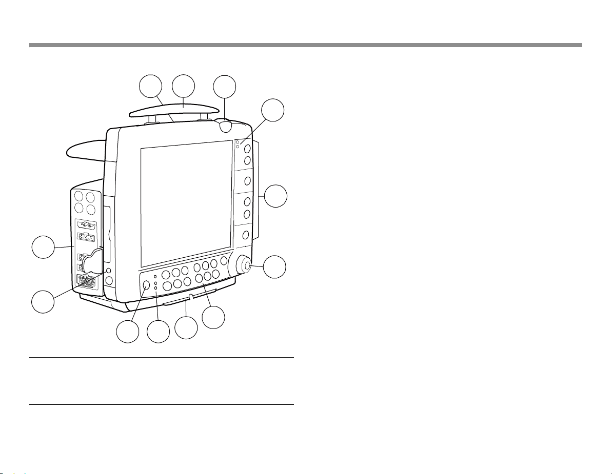
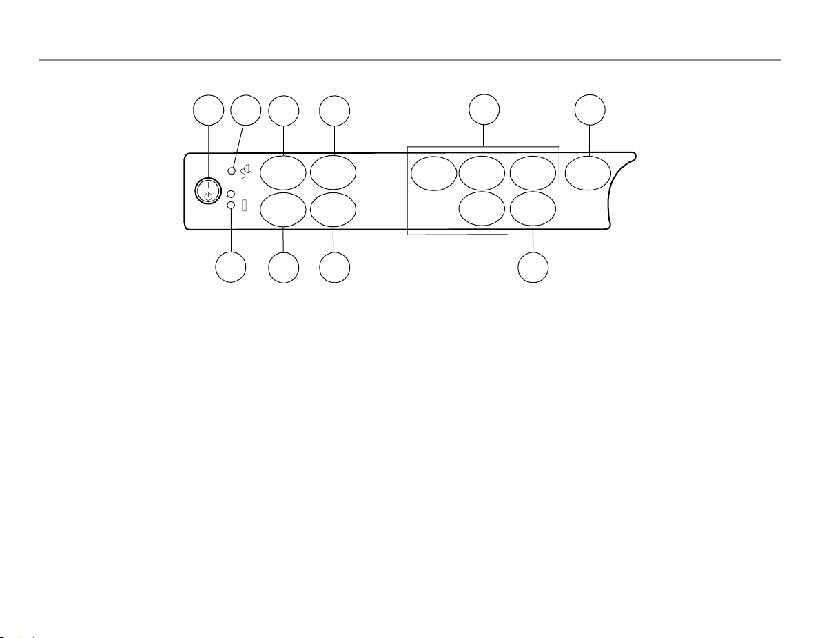
Monitor introduction
1
12
11
10
9
11
2
3
(1) Battery compartment, see below
(2) Transportation handle
(3) Alarm light, see page 39
4
(4) Alarm LEDs, see page 37
(5) Side panel keys, see page 14
(6) The ComWheel
(7) Command Board keys, see page 13
(8) Guide rail for GCX mounting
(9) Mains power and battery LEDs, see page 15
(10) ON/standby key
(11) Defibrillator & IABP synchronization connector (marked with X5)
5
(12) Measurement modules, see page 19
6
7
8
WARNING: If you accidentally drop the monitor or
modules, have them checked by authorized service
personnel prior to clinical use.
Page 18
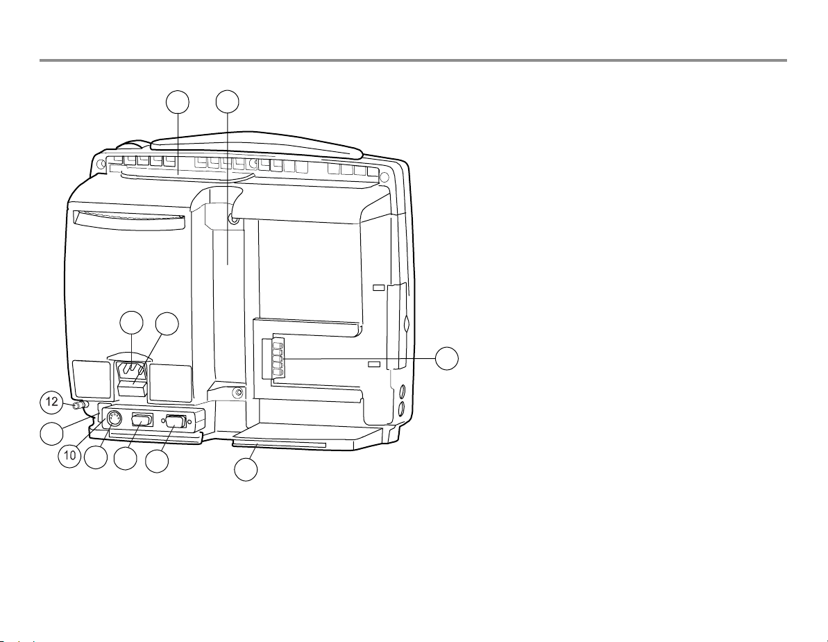
Rear panel connections
11
1
5
6
9
8
7
2
4
(1) Battery compartment
(2) Slot for infusion pole mount
(3) Module connector (marked with X4)
(4) Guide rail for GCX mounting
(5) Receptacle for power cord
(6) Fuse holder
(7) Serial port (marked with X9)
(8) Network ID connector (marked with X8)
(9) Connector for future use (marked with X7)
(10) Accessory: multi I/O adapter (with connectors 7 - 9
above)
(11) Network connector
(12) Equipotential connector
3
12
Page 19
Command Board keys
13
1
10
2
Admit/
Discharge
Monitor
Setup
9
43
Pt.Data
& Trends
Print/
Record
8
(1) ON/standby key
(2) Mains power ON (lit) or OFF (dark): indicates mains or external DC
power
(3) For admitting or discharging a patient; for selecting user modes
(4) For viewing trends and alarm history
(5) For activating parameter specific menus. NOTE: All modules do
not measure all of these parameters. For more information, see
page 19
6
Normal
Screen
ECG
5
NIBP
Airway
Gas
Invasive
Pressures
Others
7
(6) For returning the Normal Screen view to the screen
(7) For activating pulse oximetry, impedance respiration and
temperature setup menus
(8) For printing and recording different trends and waveforms
(9) For setting up the monitor and for activating the Help menu
(10) Battery operation LEDs, see page 15
Page 20
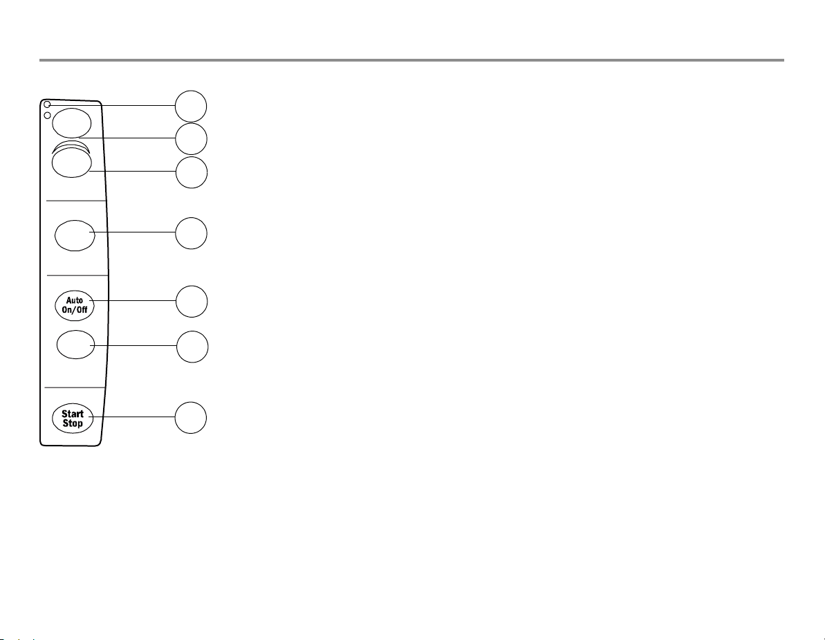
Side panel keys
r
Silence
Alarms
Alarms
Setup
Invasive Pressu
Zero
ALL
NIBP
Alarm LED indicators: see page 37
1
For silencing the alarms, see page 40
2
For activating the Alarms Setup menu
3
For zeroing the invasive pressure channels, see page 71
4
NOTE: Functional with the E-PSMP module only.
For starting the NIBP autocycling, see page 68
5
Start
Cancel
Recorder
6
For starting or stopping the NIBP manual cycling, see page 68
For starting or stopping local recording, see page 41
7
NOTE: Functional with the N-FREC and N-FCREC modules only.
14
Page 21
Batteries
The B30 monitor allow to use two lithium-ion batteries at most,
located in the battery compartment. They can be charged
separately, and screen symbols and monitor frame LEDs indicate
their charging level and possible failure, see table on the right. You
can also check the battery status through
Setup.
If you wish to have the battery charge visible at all times, select it in
one of the digit fields: Monitor Setup - Screen Setup - Digit Fields -
Battery. You can now see how much charging time is left for each
battery separately both in numbers and as symbols, and the total
charging time in numbers.
Monitor Setup - Battery
15
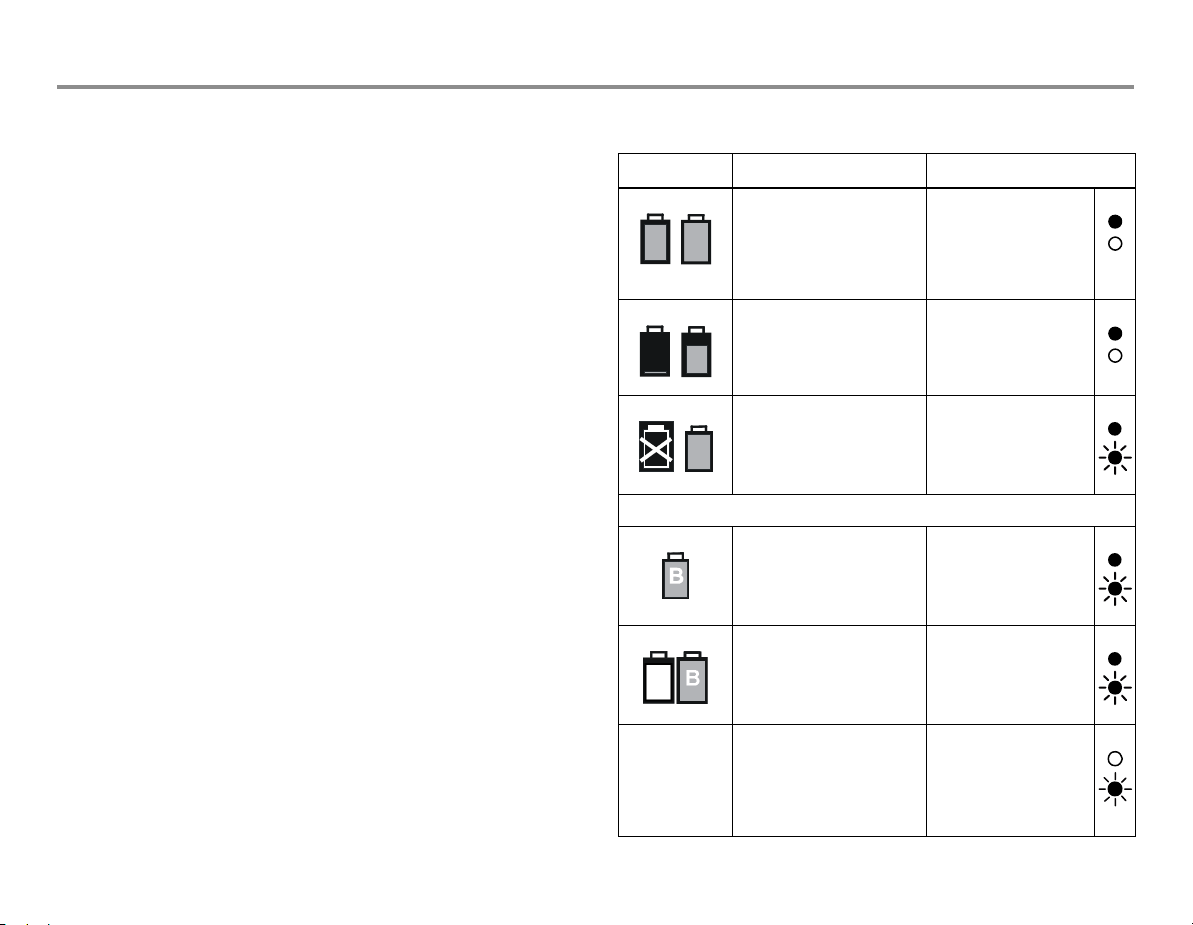
Battery indicators
Screen Explanation Front panel battery LEDs
Monitor is battery
powered. Batteries are
B
A
B
A
fully charged; the size of
the green bar indicates the
charging level.
Monitor is battery
powered. Battery A is
B
empty, battery B charge is
ok.
Green lit
Orange dark
Green lit
Orange dark
NOTE: Always use the B30 monitor with battery inserted. Otherwise
all trend data and temporary settings are lost if the power cable is
detached from the mains.
NOTE: When the monitor is battery powered, the green battery LED
is on. When the monitor is mains powered, the green mains LED is
on. See also sections "Conditioning the batteries" and "Messages."
NOTE: When useable batteries are installed, if the monitor loses AC
power, it automatically switches to battery power without
interruption of operation.
Monitor is battery
powered. Battery A failure,
battery B is full.
B
NOTE: If both batteries fail, the green battery LED is dark.
Monitor is battery
powered. Battery A
missing, battery B is full.
Monitor is mains powered.
Battery A is being charged
(white bar), battery B is
already charged.
no symbol Monitor is mains powered.
'No battery backup'
message on screen.
Batteries have failed or
they are not inserted.
Green lit
Orange flashing
Green lit
Orange flashing
Green lit
Orange flashing
Green dark
Orange flashing
Page 22
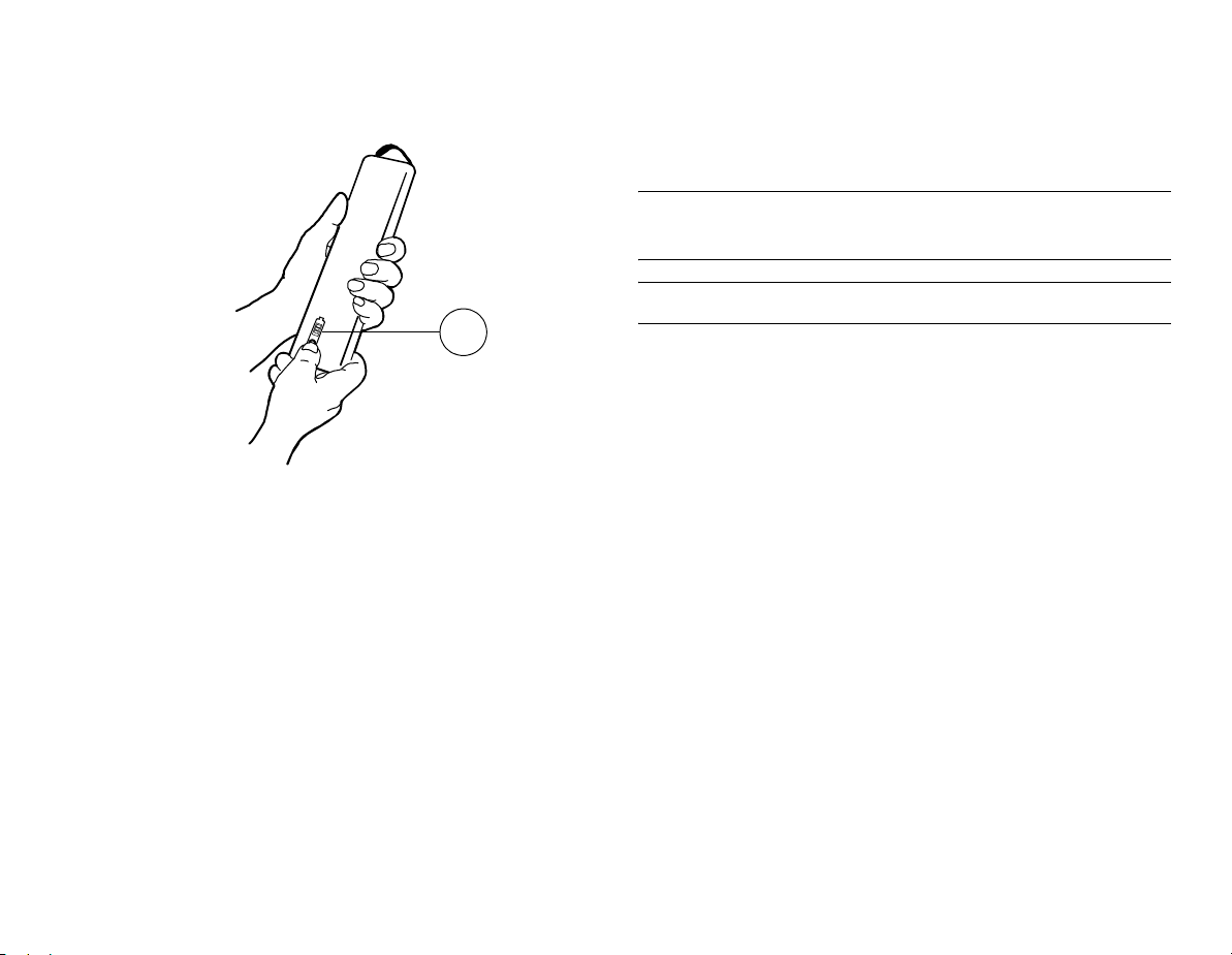
Checking the battery charge when the monitor is turned
off
1
When the monitor is turned off, you can check the battery charging
level by pressing the test button on the battery as indicated in the
drawing. The charging indicator bar (1) lights up and the number of
lit segments indicates the charging level.
WARNING: Do not incinerate a battery or store at
high temperatures, as it will explod
CAUTION: Do not dismantle the battery.
16
Page 23
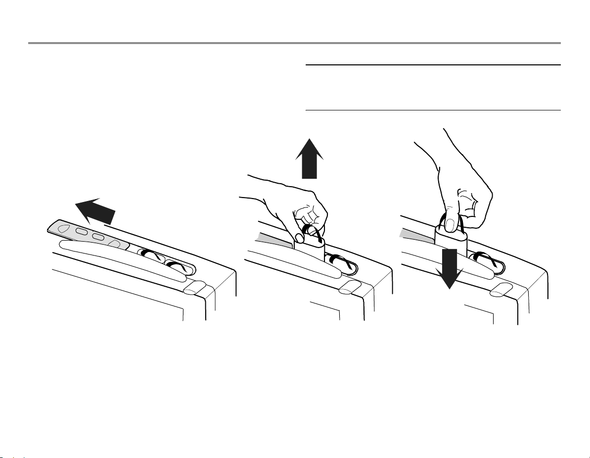
Replacing the batteries
Battery capacity indicators in the upper right corner of the screen
tell you when you should replace a battery, and which one is out of
charge, missing or not working, see above. You can replace one
battery at a time.
A
B
17
CAUTION: After replacing a battery, always make sure
to close the battery compartment by sliding the lid back
to the right until it clicks.
(1) Open the lid of the battery compartment
located behind the transportation handle
by sliding it to the left.
(2) Lift up the battery you want to change.
Check the indicators and messages on
screen to make sure that you change the
battery with lower charge.
(3) Push in the new battery. Make sure that
the charging indicator is facing forward
and push the battery down all the way.
Check the monitor indicators, see above.
Page 24

For your notes:
18
Page 25
19
Measurement modules
There are five modules for the B30 monitor: hemodynamic Patient
Side Modules E-PSMW and E-PSMPW, and the B30 monitor specific
Extension Modules N-FREC, N-FCREC and N-FC.
You can use simultaneously either one E-PSM(P)W module or one
N-Fx module or one of each. See the following pictures and
explanations for module features.
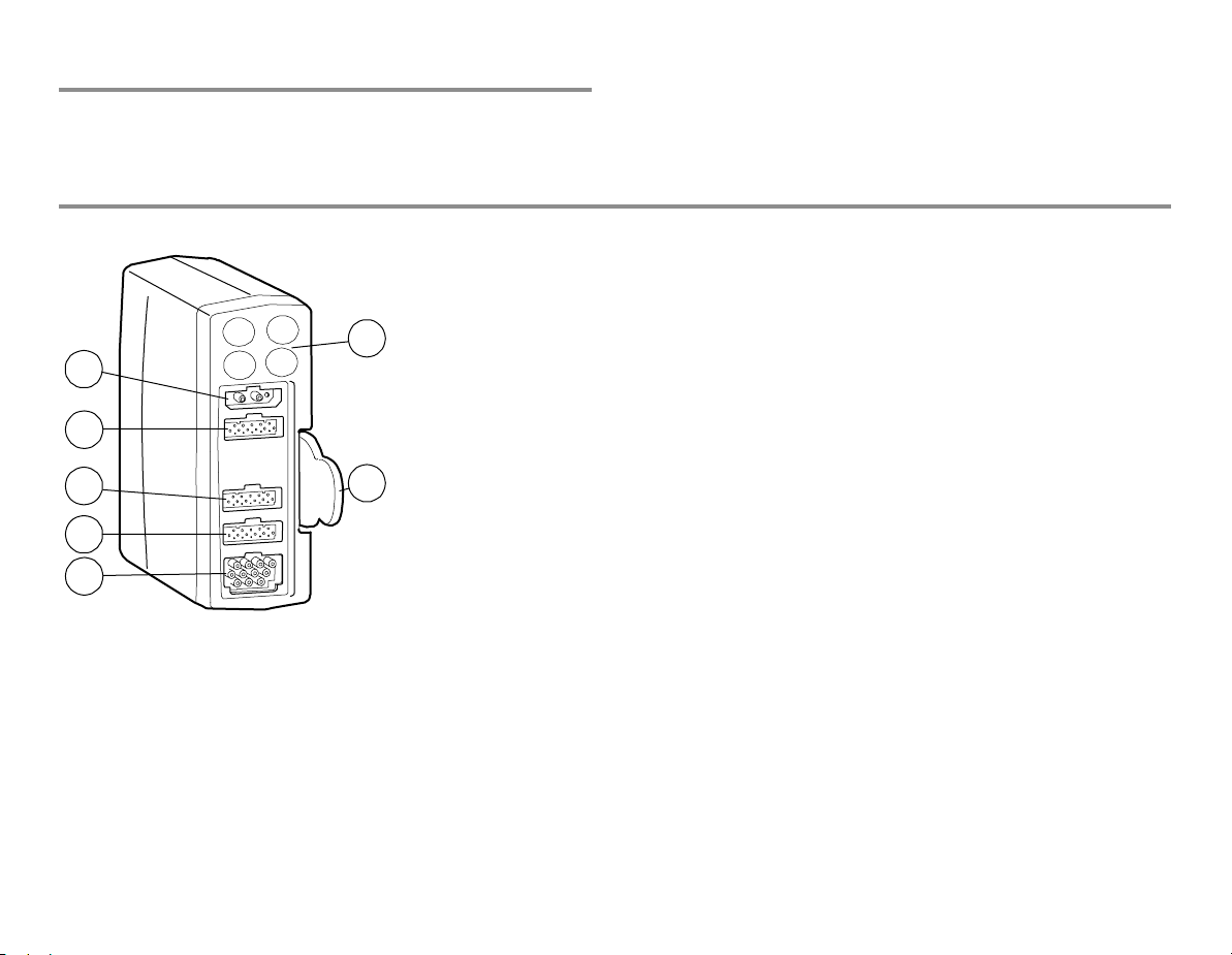
Patient Side Modules E-PSMW and E-PSMPW (in the drawing)
(1) Module keys, see below
(2) NIBP connector
(3) InvBP connector in the E-PSMPW only: 2-channel
1
2
3
4
7
5
6
(4) Temperature connector: 2-channel measurement
(5) SpO
(6) ECG (3/5) and impedance respiration connector
(7) Tab for removing the module
measurement
connector
2
Page 26

Module keys Module versions
The Patient Side Modules have the following measurement
Auto
On/Off
Auto On/Off: for starting or stopping the
NIBP automatic cycling, see page 68
capabilities:
E-PSMW:
− Non-invasive blood pressure
Start
Cancel
Start Cancel: for starting or stopping the
NIBP manual cycling, see page 68
− Temperatures
− Pulse oximetry
− ECG and impedance respiration
Zero P1
Zero P2
In E-PSMP only:
Zero P1: for zeroing pressure channel P1
Zero P2: for zeroing pressure channel P2
E-PSMPW (in the drawing above):
− Non-invasive blood pressure
− Invasive blood pressures
− Temperatures
− Pulse oximetry
− ECG and impedance respiration
20
Page 27
21
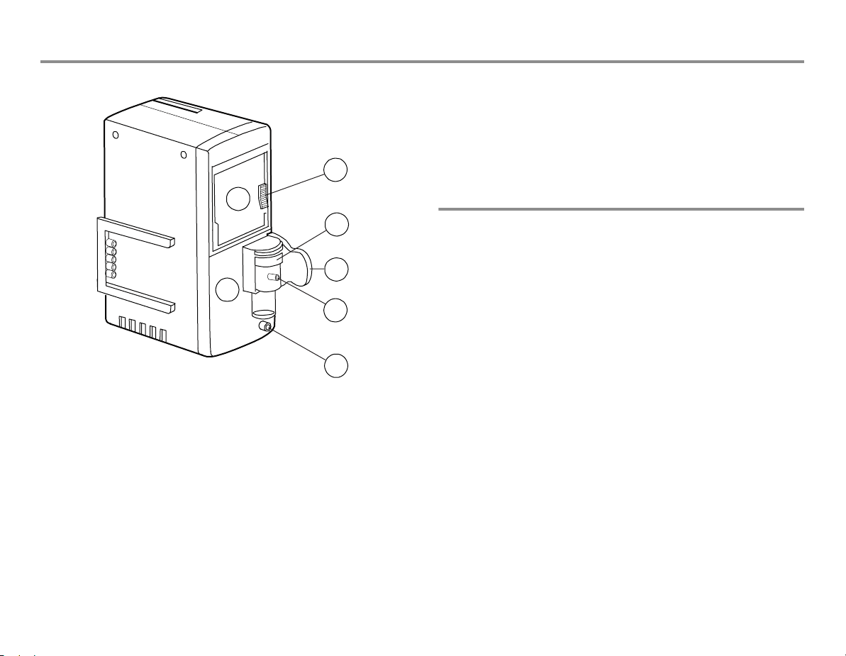
Extension Modules N-FREC, N-FCREC (in the drawing) and N-FC
(1) Recorder, in N-FREC and N-FCREC
(2) Paper compartment lever
(3) CO
(4) Water trap
2
1
4
5
3
6
7
(5) Tab for removing the module
(6) Sample gas inlet
(7) Gas outlet
Module versions
The Extension Modules have the following measurement capabilities
and features:
N-FREC:
− Built-in strip chart recorder for local recording
N-FCREC (in the drawing):
− Built-in strip chart recorder
− CO
N-FC:
− CO
measurement, in N-FCREC and N-FC
2
measurement
2
measurement
2
Page 28
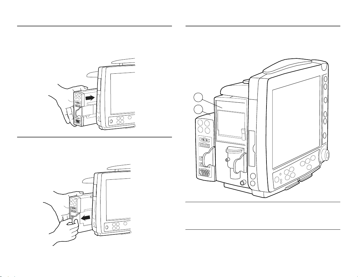
Inserting a module
1. Align the module with the insertion guides. E-PSM(P)W and N-Fx
modules are all inserted the same way.
2. Push the module into the monitor frame until it clicks:
Removing a module
1. Pull the module outwards using the tab. Make sure not to drop it
when it comes out.
Using two modules
To install an E-PSM(P)W and an N-Fx module:
1. Insert the N-Fx module first as explained in "Inserting a module."
2. Attach the E-PSM(P)W to the N-Fx.
1
2
WARNING: When detaching modules, be careful not
to drop them. Always support with one hand while
pulling out with the other.
22
Page 29

Monitoring basics
23
Navigating in menus
A menu is a list of functions or commands. To display a menu, press
one of the hard keys. Selections in the menus are made with the
ComWheel. For example, to change the ECG display:
•Press the ECG key to open the function menu.
• Turn the ComWheel to select the desired function in the menu.
• Push the ComWheel to open a submenu or an adjustment
window.
• Push the ComWheel to confirm the selection.
Using modes
The B30 monitor has six user modes. These user modes are
predefined combinations of settings. They determine, for example,
what is displayed on the screen and in trends and what the alarm
limits are. In other words, by choosing a specific mode you get
suitable settings on the screen without having to choose all features
one by one.
Modes can be hospital specific. The monitor starts in start-up mode,
which is one of the user modes chosen during configuration. The
default modes are STEP-DOWN, ED, PACU, CCU, NEURO and
PEDIATRIC. For more information about the default user modes, see
the "Default Configuration Worksheet" delivered with the monitor.
For more information about the installation settings and user
modes, see the "User's Reference Manual."
Page 30

For your notes:
24
Page 31

Setting up the monitor before use
Before starting to use the monitor, check the monitor installation
settings and what is configured in different user modes, and make
the necessary changes. The user modes can be hospital-specific.
Default modes are STEP-DOWN, ED, PACU, CCU, NEURO and
PEDIATRIC. For more information about the factory default user
modes, see the "Default Configuration Worksheet" For more
information about the installation settings and user modes, see the
"User's Reference Manual."
25
Passwords
NOTE: If you want to make changes that require a password, we
recommend you contact the system administrator.
• The default password for entering the Install/Service menu is
16 4 34.
• The default password for entering the Save Modes menu is
13 20 31.
Setting time and date
NOTE: If the monitor is connected to the Central, it follows the
Central's time settings and the Time and Date menu is not available.
NOTE: You cannot change the monitor's time settings after the
patient has been admitted.
1. Press
2. Turn and push the ComWheel to set the time and date.
Monitor Setup and select Time and Date
Battery setup
Through this menu, you can check the battery status:
1. Press the
2. Select Battery Setup. Battery information is now available.
Monitor Setup key.
Page 32

Changing the monitor installation settings
The monitor installation settings are the same in all user modes. The
changes are preserved until changed again. Press Monitor Setup,
enter the password and select Install/Service - Installation.
Units
Change units for height, weight and blood pressure.
You can change temperature units through
and CO
permanent.
units through Airway Gas - CO2 Setup. The changes are
2
Others - Temp Setup
Alarm options
Show Limits: Select YES to show alarm limits in digit fields.
Show Audio ON/OFF: Select YES to enable alarm silencing. Selecting
NO (default) disables silencing options in the Audio ON/OFF menu in
Alarms Setup.
NOTE: The Show Audio ON/OFF setting should be changed only by
the system administrator.
Alarm Light Select NO to disable the alarm light.
Latching Alarms: Select YES to keep alarm messages on screen until
Silence Alarms key is pressed.
Reminder Volume: Adjust volume of audible alarm reminder tone.
Alarm Tones: Select ISO 9703-2 standard tones or general tones.
Printer
ECG Printout Type: Select 2x6-25, 2x6-50 or 3x4-25.
Printer Connection: Select printer connection (default: None).
Paper Size: Select A4 or Letter.
NOTE: Network printer only.
Monitor settings
Parameter Settings: Set CO2 humidity compensation.
26
Page 33

27
Changing the user modes
NOTE: If you want to make changes in user modes, we recommend
you contact the person responsible for the configuration. When new
settings are saved, they should be marked in the "Default
Configuration Worksheet" See below for instructions on how to
change the modes permanently.
1. Select the user mode you wish to change through Admit/
Discharge
2. Make necessary changes (sweep speeds, parameter colors,
report contents, Normal Screen layout, screen setup, trendsetc.).
To change a parameter setup, press a parameter key and go to
the setup menu. For instructions, see relevant parameter
sections. To change alarm limits and volume, press the Alarms
Setup
3. Confirm changes through
Save Modes - Save. You can save the changes also in other
modes. If you do not save the changes in the modes, they are
temporary and valid only until you discharge a patienor change
the mode or until more than 15 minutes has elapsed from the
turn-off of the monitor. Entering Save Modes requires a
password, see "Passwords" above.
- Select Mode.
side panel key. For instructions, see "Alarms."
Monitor Setup - Install/Service -
Changing the startup mode
1. Select Monitor Setup - Install/Service - Save Modes.
2. Select Startup Mode - 1, 2, 3, 4, 5 or 6.
Renaming a mode
1. Select Monitor Setup - Install/Service - Save Modes.
2. Select the mode, select Name and give a new name.
Loading modes
1. Select Monitor Setup - Install/Service - Save Modes.
2. Select Load Modes and load to/from network.
Page 34

Changing the waveform sweep speeds
1. Select Monitor Setup - Sweep Speeds.
2. Select the parameters and adjust the values. Slow waveforms
show the amplitude changes better.
Changing the parameter colors
To change colors for parameter waveforms, digits and trends:
1. Select
2. Select Colors.
3. Select colors for parameters.
Monitor Setup - Install/Service.
Changing the recorder settings
1. Press Print/Record.
2. Select Record Waveforms and select the recorded waveforms,
delay, paper speed and length, and select if you wish to record
waveforms on alarms.
3. Select Record Trends and set the numerical trend resolution and
trend type and select the graphical trend recorded in upper and
lower field.
Changing the printer settings
1. Press Print/Record.
2. Select Print Graphical.
3. Select the pages to print and how many hours to print on one
page.
Changing the Normal Screen layout
1. Press Monitor Setup.
2. Select Screen Setup:
• Waveform Fields: Select the displayed waveforms.
• Digit Fields: Change the contents of a field or turn it off.
• Split Screen: Select what you wish to display with the
waveforms (Trend or None).
• Minitrend Length: Select the length of the minitrend. NOTE:
Minitrend is displayed if you choose the Split Screen option
Trend.
Changing the display brightness
1. Press Monitor Setup.
2. Select Display brightness.
3. Select from 10 to 100 %.
28
Page 35

29
Setting the default trend
You can select graphical or numerical trends to be displayed by
default.
1. Press Monitor Setup and select Install/Service.
2. Select Trends.
3. Select Default Trend and Graph or Num.
Configuring trend pages
To select the parameters that are displayed on the graphical trend
pages:
1. Press
2. Select Trends - Graphical Trends.
3. Select the graphical trend page you want to change.
4. Select parameters for fields.
Monitor Setup and select Install/Service.
Setting trend lengths and scales
Press Pt.Data & Trends:
•Select Trends - Graphical - Time Scale and select the trend
length.
•Select Trends - Graphical - Trend Scales and adjust the
scales.
Page 36

For your notes:
30
Page 37

Entering and loading patient data
31
Entering patient data
When you admit a patient, you must enter all relevant data:
1. Press the
2. Enter patient data by pushing and turning the ComWheel.
Admit/Discharge and select Admit Patient.
Loading patient data
If the patient has already been admitted on the same monitor, press
Admit/Discharge and select:
•Contin. Previous
Select this to load the most recent patient trends from the monitor
memory when less than 15 minutes has elapsed from the turn-off.
NOTE: This selection is available if the patient case is already
admitted on this monitor.
Saving data
The monitor continuously saves patient data, such as trends. Saving
is activated once the patient is admitted. The monitor saves
automatically:
− In the monitor memory the most recent patient data up to 72
hours if the network is not in use.
− In the network the most recent patient data up to 72 hours from
2 to 90 days depending on the configuration.
Page 38

For your notes:
32
Page 39

Starting and ending
33
Preparations
NOTE: Before using the monitor for the first time with batteries,
charge the batteries to their full capacity (charging time 2 hours per
battery pack).
1. Plug in the measurement modules.
2. Turn on the monitor from the ON/standby key. The monitor
performs a self-test to ensure correct functioning.
3. If necessary, change the user mode: Press the
Discharge
Modes are preconfigured but if desired, they can be changed.
Changing the modes is described briefly in "Screen setup."
NOTE: Changing the mode also changes settings, such as the alarm
limits. For details, see the "Default Configuration Worksheet"
The monitor automatically reconfigures the display when modules
are inserted. Reconfiguration of the display may take up to five
seconds.
key and select Select Mode.
Admit/
WARNING: Connect only one patient to the monitor at
a time.
WARNING: Always make sure that necessary alarm
limits are active and set according to the patient's
clinical condition when you start monitoring.
Starting monitoring
1. Prepare the patient connections according to the setup picture
in the measurement section. Use only approved supplies and
accessories, see the "Supplies and Accessories" catalog. The
alarms and parameter settings become active.
2. If necessary, adjust the waveform and digit fields; see "Screen
setup."
3. Zero invasive pressure lines; see "Invasive blood pressure."
4. Check the alarm limits; press the
Change them, if necessary; see "Alarms."
5. Start the measurement according to the instructions in the
measurement section.
6. Enter or load patient data by pressing the Admit/Discharge
key; see "Entering and loading patient data."
The patient admission happens through Admit Patient selection or
automatically when the monitor receives a patient's vital signs.
Always observe the monitor and the patient carefully during startup periods and when inserting modules.
Alarms Setup side panel key.
Page 40

Ending monitoring
1. Print necessary data: press the Print/Record key.
2. Wait until the printing is finished. Then clear the patient data and
return the settings, including alarm limits, to their defaults
through Admit/Discharge - Discharge - YES
3. Turn off the monitor from the ON/standby key if the monitor will
not be used.
4. Clean the monitor according to the instructions.
Automatic discharge of the patient
The monitor discharges a patient automatically after 24 hours when
vital signs for some parameters (ECG, Art, NIBP, SpO
(with N-FCREC and N-FC)) are not available. When this happens, all
trend data will be cleared and alarm limits set to default values.
, Resp and CO2
2
34
Page 41

Screen setup
35
Modifying the screen temporarily
•Press the Monitor Setup key and select Screen Setup.
• Change the waveform and digit field measurements, split screen
option, minitrend length and sweep speeds.
• To make other setup changes, such as scale changes, press a
parameter key and select its setup menu. For example, press the
ECG key and select ECG Setup.
Changes are valid until the monitor is turned off (+15 minutes) or
until you discharge the patient from the monitor. Only time and date
settings are stored permanently.
Modifying the screen permanently
You can make permanent changes in the screen setup. This is
described briefly in section “Setting up the monitor before use." For
information on default configuration, refer to the "Default
Configuration Worksheet"
Changing the split screen contents
You can split the Normal Screen page into two parts. The other half
of the split screen shows trend data.
1. Press the
2. Select Screen Setup.
3. Select Split Screen and choose from the options.
• Trend shows minitrends beside waveforms.
• None shows no split screen.
Monitor Setup key.
Page 42

Changing waveform and digit fields
Up to six waveforms and four digit fields can be displayed
simultaneously.
1. Press the Monitor Setup key.
2. Select Screen Setup.
3. Select Waveform Fields or Digit Fields.
Note that:
− Waveforms are always evenly spread to fill the entire waveform
area. When 3 or fewer waveforms are configured on the screen,
they are displayed in an enlarged format.
− Selecting Combine Pressures displays invasive pressures in the
same waveform field with the same zero line, but with individual
scales.
− If 5-lead ECG is measured, up to three different ECG leads can be
displayed simultaneously in different fields.
36
Page 43

Alarms
37
Enabling the alarms
To enable the alarms, connect patient cables. If the alarm source is
selected, the alarms are operative also when the measurement is
not displayed (except the impedance respiration measurement
alarms).
WARNING: Always make sure that necessary alarm
limits are active and set according to the patient's
clinical condition when you start monitoring. A
potential hazard can exist if different default alarm
settings are used for the same or similar equipment
in any single area.
CAUTION: Setting alarm limits to extreme values may
render the alarm system useless
Alarm indications
When the monitor is turned on, you will hear a beep: this tells you
that the alarm audio signal is working. Also, the alarm LED indicators
light up for a few seconds. To check them, see "Cleaning and care:
Functioning of the alarms." You can also check the functioning of the
audio signal and alarm light through Alarms Setup - Alarm
Volume or Alarm Light.
When an alarm becomes active, messages appear in the order of
priority. The alarming measurement value flashes (except for low
priority alarms) and the color indicates the alarm category; see the
table below. In some cases, there may be a message on the screen
giving more detailed information. An audible alarm is also triggered,
and the alarm LEDs on the monitor side panel indicate the alarm
level. If enabled, also the alarm light flashes red or yellow according
to alarm levels, see below.
NOTE: If the monitor is connected to the network, it also sends
alarms to the Central.
Page 44

Alarm categories
The priority depends primarily on the cause and alarm duration. The priority increasing with the duration and according to the physiological
significance.
Visual Meaning Tone pattern (selected
when the system is
Side panel LED
indicators
Alarm light (if
enabled)
configured)
Red For life threatening situations: HIGH
PRIORITY ALARM
Yellow For serious but not life threatening
problems: MEDIUM PRIORITY
ALARM
White Advisory: LOW PRIORITY ALARM Single beep - yellow LED lit dark
Adjusting limits
1. Press the Alarms Setup side panel key and select Adjust
Limits.
2. Highlight the measurement.
3. Push the ComWheel to open an adjustment window.
4. Turn the ComWheel to change limits and accept them by
pushing it. Move between selections by turning the ComWheel.
NOTE: If the monitor is connected to the network, the alarm limits
can also be changed using the Central if this feature has been
enabled in the Central configuration.
Triple + double beep every 5
seconds or continuous beep
--- -- 5 --- --/ -----
Triple beep every 19 seconds or
double beep every 5 seconds
--- 19 --- / -- 5 -- 5 --
Adjusting volume
1. Press the Alarms Setup side panel key.
2. Select Alarm Volume and adjust.
WARNING: Always make sure that the audio alarm
volume level is adequate in your care environment.
red LED flashing flashing red
yellow LED flashing flashing yellow
38
Page 45

39
Alarm light
The B30 monitor has an alarm light, located in the upper right corner
of the monitor frame, see page 11. The alarm light can be enabled
(default) or disabled through Monitor Setup - Install/Service Installation - Alarm Options - Alarm Light When enabled, it flashes
red (high priority) or yellow (medium priority) according to the
currently active highest priority alarm.
To adjust the brightness of the light:
1. Press the
2. Select Alarm Light and adjust with the ComWheel. During
adjustment the red light is on to help you determine a suitable
brightness level.
Alarms Setup key.
Alarm activation
To enable the alarms, connect patient cables. If the alarm source is
selected, the alarms are active also when the measurement is not
displayed (except the impedance respiration alarms). When an
alarm becomes active, messages appear in order of priority. See
default settings presented in the "Default Configuration Worksheet."
NOTE: Limit alarms are active after one minute from turning on the
monitor or after discharging the patient.
Individual alarms have their own specific requirements before they
become active, for example:
− Apnea requires five breaths to be activated.
− Invasive pressures need to be within alarm limits for 20 seconds
after zeroing.
Changing source
For NIBP, P1 and P2 (with E-PSMPW), you can select which measured
values trigger the alarm. One or several alarm sources may be
active at a time.
1. Press the
Limits.
2. Select the measurement.
3. If the highlight is in the adjustment window, push the ComWheel
until you get to the menu selections.
4. Select the desired alarm source ON.
Alarms Setup side panel key and select Adjust
Showing alarm history
1. Press the Pt.Data & Trends key.
2. Select Alarm History A list of the last 20 alarms is displayed.
Page 46

Silencing audible alarms temporarily
To silence alarms for two minutes, press the Silence Alarms side
panel key. To silence them for five minutes, press the key for more
than five seconds.
If the alarms are not active when you press the
side panel key, they are pre-silenced for two or five minutes.
During silencing, all new alarms for the same reason and all alarms
for a different reason are indicated visually.
To silence the individual alarm that is currently active, press the
Silence Alarms
Silence Alarms side panel key twice. This does not pre-silence the
upcoming alarms.
NOTE: If the monitor is connected to the network and the network
connection is lost, the silenced alarms are reactivated and the
volume level is automatically set to 7.
Reactivating silenced alarms
•Press the Silence Alarms side panel key during the silencing
period.
The alarm sounds of new alarms are activated. Silenced alarms are
active after a two-minute period. Apnea alarm is activated after
three breaths.
Silencing audible alarms permanently
1. Press the Alarms Setup side panel key and select Audio ON/
OFF. If this option is not selectable, see “Alarm options.”
2. Select Silence Apnea, Silence ECG, Silence Apn&ECG or Silence
ALL.
If an active alarm is silenced, the monitor gives a reminder beep
every two minutes. By default, silencing alarms is set unselectable
and can only be activated through the Installation menu. For more
information, see "Setting up the monitor before use" or the "User's
Reference Manual."
Reactivating alarms
•In Alarms Setup menu, select Audio ON/OFF and select Activate
Alarms.
NOTE: If the monitor is connected to the network, the bedside alarms
can also be silenced using the Central if this feature has been
enabled in the Central configuration.
WARNING: When the alarms are silenced, observe the
patient frequently.
40
Page 47

Printing and recording
You need
− Laser printer for printouts (PCL5 compatible, min. 2Mb memory)
NOTE: Network printer only.
− Optional N-FREC or N-FCREC module for recording
− Thermal paper for the recorder
NOTE: Before you start printing, check that the printer is operational.
NOTE: Recordings on thermal paper may be destroyed when
exposed to light, heat, alcohol, etc. Take a photocopy for your
archives.
41
Side panel key
Use the side panel key to start and stop recording immediately.
Starts and stops recording
Page 48

Printing with a laser printer
Selecting a printer
1. Press the Print/Record key.
2. Select Printer Connection.
3. Select the printer from the list.
Printing graphical trends
To print graphical trends:
1. Press the
2. Select Print Graphical.
3. Select the page(s) to print.
4. Select Print Graphs.
Print/Record key.
Printing currently displayed screen contents
You can print currently displayed trend data.
To print trend data:
•Press the
• Trends - Graphical/Numerical - Print Page
Pt.Data & Trends key and select:
42
Page 49

43
Recording with the recorder
NOTE: You need the N-FREC or N-FCREC module with the built-in
recorder.
Recording numerical trends
You can record the current values of measured parameters.
1. Press the
2. Select Record Trends - Record Numerical.
3. You can stop recording by selecting Stop Numerical.
Print/Record key.
Selecting the format for the recorded numerical trends
You can select the format for the recorded numerical trend to be
either Num. (vertical) or Tab. (horizontal):
1. Press the
2. Select Record Trends - Num Trend Type and Num. or Tab.
Print/Record key.
Recording graphical trends
1. Press the Print/Record key.
2. Select Record Trends - Record Graphical.
3. You can stop recording by selecting Stop Graphical.
Trends are recorded for the time period that corresponds to the time
scale of the graphical trends.
To choose the time scale:
1. Press the
2. Select Trends.
3. Select Time Scale - 20 '/1 h/2 h/4 h/6 h/8 h/10 h/12 h/24 h/36 h/
48 h/72 h.
To select the parameters for the graphical trends:
1. Press the Print/Record key.
2. Select Record Trends.
3. Select Graphic. Trend 1 or Graphic. Trend 2.
4. Select the parameter.
Pt.Data & Trends key.
Page 50

Recording on alarms
1. Press the Print/Record key.
2. Select Record Waveforms.
3. Select Start on Alarms - YES.
Recording is activated when the following alarms reach the red level:
Asystole, Tachy/Brady, Art high/Art low, V Fib, V Tachy.
Art and ECG1 waveforms are recorded. Selections are
preconfigured.
Recording waveforms
You can record three waveforms to a local recorder, and two to four
waveforms to a network recorder:
1. Press the Print/Record key.
2. Select Record Waveforms - Record to Local. If the monitor is
connected to the network, you can also use the network
recorder by selecting Record to Net. The network recorder uses
the settings of the Central.
3. Stop recording by selecting Stop Waveforms.
Changing the paper speed
To see the waveforms more clearly or more generally, change the
paper speed:
1. Press the Print/Record key.
2. Select Record Waveforms - Paper Speed.
To select other waveforms for recording, press the
key.
44
Print/Record
Page 51

Trends
Trends view
(1) Measurement trend field
(2) Real time ECG
(3) Numerical value of a measurement at the trend cursor point
(4) Time and marker field
(5) Trend page number
45
Symbols
Trend bar: the gap shows the blood pressure mean
value
NIBP trend bar
Indicator of change -for example, ST relearning or
zeroing of an invasive blood pressure channel/
changing a label
Page 52

Viewing graphical trends
1. Press the Pt.Data & Trends key.
2. Select Trends - Graphical.
• To see more parameters, select Scroll Pages and scroll with
the ComWheel.
• To see more data, select Cursor and scroll the page left and
right with the ComWheel.
Viewing numerical trends
1. Press the Pt.Data & Trends key.
2. Select Trends - Numerical.
• To see more pages, select Scroll Pages and scroll with the
ComWheel.
• To see more data, select Cursor and scroll the page up and
down with the ComWheel.
Graphical trends contain four trend pages each having up to six
preconfigured fields with different parameters. Five fields can be
displayed, and six fields can be printed. Real-time ECG waveform is
always displayed at the top of each page.
The graphical trend time scale varies from 20 minutes to 72 hours
and the resolution from 10 seconds to one minute. With the 20
minute trend length, the displayed time period is 30 minutes and the
resolution 10 seconds. With trend lengths from one to 72 hours, the
displayed time period is 72 hours and the resolution is one minute.
For HR, ST, PVC, SpO
select the scale in the Trend Scales menu.
and temperature measurements you can
2
Numerical trends contain four pages with the maximum of 72 hours
of trend data. Real-time ECG waveform is displayed at the top of
each page.
Erasing trends
1. Press the Admit/Discharge key.
2. Select Discharge.
If the monitor has been turned off from the ON/standby key but the
patient has not been discharged, the trend data will be stored in the
memory for 15 minutes.
46
Page 53

Cleaning and care
47
Daily and between patients
• Wipe the monitor and module surfaces.
• Wipe the ECG trunk cable, NIBP cuff and cables and SpO2
sensors. Avoid excessive use of liquids.
• Change or sterilize all airway and invasive patient accessories.
• Clean, disinfect or sterilize reusable temperature probes.
• Empty the water trap.
• Check that the accessories, cables and monitor parts are clean
and intact.
Every two months
• Change the water trap.
Every six months
• Refresh the batteries, see below.
• Perform gas calibration, see below.
Permitted detergents
−
Mild hospital detergents
Permitted disinfectants
−
Ethanol
− Isopropyl alcohol
− Chlorite compounds
− Glutaraldehyde
Points to note:
−
Do not use hypochlorite, acetone-, phenol- or ammonia based
cleaners.
− Do not autoclave the device or its parts.
− Do not immerse any part of the device in liquids or allow liquid to
enter the interior.
− Do not apply pressurized air to any outlet or tubing connected to
the monitor.
For details about cleaning, disinfecting and sterilizing the reusable
accessories, see the instructions for use in the accessory package or
the "Supplies and Accessories" catalog. Do not reuse single-use
disposable accessories.
WARNING: If liquid has accidentally entered the
system or its parts, disconnect the power cord from
the power supply and have the equipment serviced
by authorized service personnel.
CAUTION: Do not use hypoclorite, ammonia-, phenol-, or
acetone based cleaners. These cleaners may damage
the monitor surface
.
Page 54

Before cleaning
1. Turn off the monitor from the ON/standby key.
2. Disconnect the power cord.
After cleaning
1. Let dry completely.
2. Reconnect the power cord and turn on the monitor.
More comprehensive checking
See the "Technical Reference Manual."
Pulse oximetry sensors
The GE Healthcare pulse oximetry sensors are latex-free. Take
possible patient allergies into account also when selecting the
cleaning agent.
1. Detach the sensor from the patient and the monitor.
2. Wipe the sensor with mild detergent solution. Allow it to dry
completely before use.
Sensor can be disinfected with chlorite compounds.
The sensors may be sterilized using an ethylene oxide mixture at 50
to 60 °C/ 120 to 140 °F.
NOTE: After ethylene oxide sterilization, sensors must be well
aerated in a ventilated place.
WARNING: A damaged sensor or a sensor soaked in
liquid may cause burns during electrosurgery.
48
Page 55

49
Water trap in the N-FCREC and N-FC modules
• Empty the container whenever half full.
• Change the water trap every two months and when the text
'Replace D-Fend' appears.
• The water trap cartridge is disposable. Do not wash or reuse the
cartridge.
WARNING: After cleaning, ensure that every part of
the system is dry before reconnecting it to the power
supply.
CAUTION: Do not disinfect or open the water trap
cartridge. Do not touch the water trap membrane. The
hydrophobic membrane is damaged if any cleaning is
attempted other than rinsing with water.
Conditioning the batteries
Condition batteries regularly to maintain their useful life. This is best
done on an external charger. Condition a battery every six months
or when the message 'Replace Battery A' or 'Replace Battery B'
appears on the screen. Always observe the messages and symbols
on the screen to see the battery status. You can also check the
status through
information, see "Replacing the batteries", "Symbols" and
"Messages."
Detailed instructions for refreshing the batteries can be found in the
“User's Reference Manual.”
Monitor Setup - Battery Setup. For more
Power interruption
NOTE: Always use the monitor with batteries inserted. Otherwise all
trend data and temporary settings are lost if the power cable is
detached from the mains.
If the monitor is turned off, trend data and the latest user-made
settings remain in the monitor memory for 15 minutes even if the
mains power is interrupted. If not, contact service personnel. After 15
minutes, trend data is lost and the monitor returns to the user
default settings (startup mode).
Changing fuses
1. Remove the power cord if used.
2. Remove the fuse holder by pushing the locking pin and pulling
the holder gently out.
3. If a fuse is blown, replace it with a fuse of the correct type and
rating.
Page 56

Regular checks
When you start monitoring, check that:
• The module is firmly in place.
• Accessories are intact and properly connected.
• You have selected desired parameters to be displayed in the
digit and waveform fields.
ECG and impedance respiration
• Check that the message 'Leads off' disappears and waveforms
are displayed when the cable is connected to the patient.
Pulse oximetry
• Check that the red light is lit in the sensor.
• Check that the SpO2 value is displayed and the message
'SpO2 probe off' disappears when the sensor is connected to the
patient.
Temperature
• Check that the temperature value is displayed when the probe is
connected to the patient.
InvBP
• Check that the monitor recognizes cable connections (activates
the display) for all the pressure channels used and the pressure
values are shown.
• Make sure that all transducers are zeroed correctly.
NIBP
• Ensure that you are using correct cuff size and have selected
correct inflation limits. For children and when using hoses
without identification, the inflation limit must be set manually.
• Check that the cuff hose detection works properly.
• Check that the pressure values are displayed.
• Start the Venous Stasis mode and check that the pump is not
restarting during the measurement. If it does, the cuff may be
leaking.
Airway gas (CO2)
• Check that the water trap is empty.
• Occlude the sampling line and check that the 'Sample line
blocked' message appears within 30 seconds and gas
waveforms are showing zero at the same time.
50
Page 57

51
Functioning of the alarms
• Set a parameter value outside the alarm limits. For example,
connect the SpO2 sensor and adjust the SpO2 High limit under
the measured SpO
priority according to sequence given in the "Alarm categories"
table on page 38.
• Check that the yellow and red LEDs function as indicated in the
table.
• Check that the alarm light functions if it is enabled.
NOTE: Although SpO
often OFF by default, it is easy to use for alarm checking.
If the monitor does not work as described, refer to "Troubleshooting".
values. The alarms go from low to high
2
may not be the best example because it is
2
Safety checks for software
The GE Healthcare software design controls include performance of
a risk analysis using methods consistent with ISO 14971 Medical
devices - Application of risk management to medical devices.
The monitor software employs watchdog timers, self-monitoring
activities (memory, communication and sensor checks and so on),
and power-on self-diagnostics (for example, memory checksums).
For example, for SpO
sensor and, if excessive sensor current is detected, the message
‘SpO2 faulty probe’ is displayed both in the SpO
the monitor message field, and the old SpO
the display.
the software continuously monitors the SpO2
2
number field and
2
data is removed from
2
Page 58

Calibrating
NOTE: % is used for CO2 regardless of selected units.
NOTE: See the "Supplies and Accessories" catalog for correct
regulator and gas.
NOTE: Ensure that the calibration gas and regulator are functioning
properly before calibration. Perform annual maintenance on the
regulator as required.
NOTE: Use only specified GE Healthcare calibration gas sampling
line; wrong line length or diameter can cause incorrect calibration.
See the "Supplies and Accessories" catalog.
NOTE: Do not wash or disinfect calibration gas sampling lines.
Starting the calibration
1. Turn on the power. Let the monitor warm up for 30 minutes.
2. Attach a regulator to the calibration gas container.
Calibrating airway gases
Follow the recommended calibration intervals (every six months in
normal use and every two months in continuous use) to ensure that
the measurement accuracy remains within specifications.
1. Attach a new sampling line to the water trap. Connect the other
end of the sampling line to the regulator on the gas container.
2. Press the
3. Wait until the texts 'Zero OK' and then 'Feed gas' appear on the
screen, open the regulator and start feeding gas. Push the
ComWheel and continue feeding gas until the text 'Adjust' is
displayed.
4. Check that the displayed gas values match the values on the
calibration gas container. Adjust with the ComWheel if
necessary.
NOTE: Calibrate the N-FCREC or N-FC module with calibration gas
755580 only and set the O
Airway Gas key and select Gas Calibration.
concentration to 20%.
2
Calibration check for temperature, NIBP and invasive blood pressures
Calibration check for temperature, NIBP and invasive blood
pressures should be performed at least once a year by qualified
service personnel as a part of the Planned Maintenance, see the
"Technical Reference Manual."
52
Page 59

ECG and ST
You need
(1) E-PSMW or E-PSMPW module with ECG measurement capability
(2) Multi-Link 5-lead ECG trunk cable, or 3-lead ECG cable with
integrated leadwires
(3) 3 or 5 leadwire set
ECG electrodes (pre-gelled electrodes are recommended). Check the
expiration date.
LEAD I
L
E
A
D
I
I
F=GREEN (IEC)
LL=RED (AAMI)
L=YELLOW (IEC)
LA=BLACK (AAMI)
L/LAR/RA
I
I
I
D
A
E
L
F/ LL
R=RED (IEC)
RA=WHITE (AAMI)
1
53
NOTE: For a comprehensive list of accessories, see the "Supplies and
Accessories" catalog.
NOTE: Keep the ECG cable, lead set and module connectors dry.
Avoid excessive use of liquids when cleaning cables and connectors.
NOTE: In 5-lead ECG, place the 5th electrode (C/V) in one of the six
places indicated, and select the corresponding V lead label.
R=RED (IEC)
RA=WHITE (AAMI)
N=BLACK (IEC)
RL=GREEN (AAMI)
L=YELLOW (IEC)
LA=BLACK (AAMI)
C=WHITE (IEC)
V=BROWN (AAMI)
F=GREEN (IEC)
LL=RED (AAMI)
R
A
2
R
L
R
L
R
A
I
L
I
A
I
L
L
L
A
I
I
I
3
Page 60

WARNING: Vibrations during intrahospital transport
may disturb ECG measurement.
Connecting ECG leadwire sets to ECG trunk cables
• For 3-lead ECG, use the Multi-Link 3-lead ECG cable with
integrated leadwires or connect a 3 leadwire set to the Multi-Link
3- or 5-lead ECG trunk cable.
• For 5-lead ECG, connect a 5 leadwire set to the Multi-Link 5-lead
ECG cable.
WARNING: Make sure that the leadwire set clips or
snaps do not touch any electrically conductive
material including earth.
Preparing the patient and applying the electrodes
1. Prepare the skin properly to ensure optimal signal quality:
• Shave any hair from the electrode sites.
• Gently rub the skin surface to increase capillary blood flow
and remove dead skin cells and oil.
• Clean the skin using a mild soap and water solution.
• Dry the skin completely before applying the electrodes.
2. Apply the electrodes (see figures and instructions above). Avoid
bones close to the skin, obvious layers of fat and major muscles.
Selecting the ECG filter
1. Press the ECG key.
2. Select ECG Setup - Filter:
STfilt filters high-frequency artifacts but catches slow ST
changes.
Monit filters high-frequency artifacts and slow ST changes.
Diagn catches high-frequency changes and slow ST changes.
54
Page 61

55
Selecting the number of electrodes for 5-lead ECG
1. Press the ECG key.
2. Select ECG Setup.
3. Select 5-lead Cable - 3elect or 5elect.
Selecting the user leads
1. Press the ECG key.
2. Select a lead for ECG1 Lead, ECG2 Lead or ECG3 Lead.
With 3-lead ECG, you can select only one user lead (ECG1 Lead).
With 5-lead ECG, you can select three user leads.
Selecting a label for V Lead
With 5-lead ECG, one V lead is measured according to the placement
of the V lead electrode.
To select a label for the lead:
1. Press the
2. Select ECG Setup - V Lead.
ECG key.
Selecting how to view ECG waveforms
• To set the number of ECG waveforms in Normal Screen, press
Monitor Setup and select Screen Setup - Waveform Fields.
With 3-lead ECG, one lead, and with 5-lead ECG, up to three
leads can be viewed at the same time.
• To cascade a lead, press ECG and select ECG2 Lead/ECG3 Lead
- Casc.
• To increase ECG amplitude, press
• To change the waveform sweep speed:
Speeds. Select Hemodynamics and adjust the value.
NOTE: The module input circuits are protected against the effects of
electrosurgery and defibrillation. However, the ECG waveform on the
monitor screen may be disturbed during electrosurgery.
ECG and select ECG Size.
Monitor Setup - Sweep
Displaying ECG grid
To view the ECG waveforms over gridlines on the screen:
1. Press the ECG key and select ECG Setup.
2. Select Grid - ON. To view without gridlines, select OFF.
Changing the HR source
1. Press the ECG key.
2. Select ECG Setup - HR Source.
• AUTO selects the first available of ECG, Art, ABP and Pleth.
Page 62

Beat sound volume
To adjust the beat sound volume of the monitor:
1. Press the
2. Select ECG Setup.
3. Select Beat Sound Volume.
4. Adjust the volume from 0 to 10. If you select 0, there is no audible
sound.
ECG key.
WARNING: The impedance respiration measurement
may cause rate changes in Minute Ventilation Rate
Responsive Pacemakers. Set the pacemaker rate
responsive mode off or turn off the impedance
respiration measurement on the monitor.
Selecting what to display with HR
You can select what is displayed with heart rate:
1. Press the
2. Select ECG Setup.
3. Select Display with HR - PR/PVC/None.
ECG key.
Monitoring pacemaker patients
1. Press the ECG key.
2. Select ECG Setup - Pacemaker and select one of the following:
• Show = Pacemaker spike is displayed on ECG.
• Sensit = Sensitive pacemaker detection; spike displayed on
ECG.
• Hide = Pacemaker spike is not displayed on ECG.
NOTE: If the patient has an atrial pacer, ST calculations can be
performed if the pacer does not coincide with the ISO point's
adjustment range.
NOTE: Pacemaker detector may not operate correctly during the use
of high-frequency (HF) surgical equipment. The disturbance of HF
surgical equipment typically causes false positive pacer detection.
WARNING: When using the electrosurgery unit,
ensure proper contact of the ESU return electrode to
the patient to avoid possible burns at monitor
measurement sites.
WARNING: Do not rely entirely upon rate meter
alarms when monitoring patients with pacemakers.
The monitor may count the pacemaker pulses as
heartbeats. In this case, asystole and ventricular
fibrillation may go undetected. Always keep these
patients under close surveillance and monitor their
vital signs carefully.
56
Page 63

Arrhythmia monitoring
NOTE: With the L-DICU08 software only severe analysis is available.
It detects asystole, bradycardia, tachycardia, ventricular fibrillation
and ventricular tachycardia.
Setting arrhythmia alarm priority
1. Press the ECG key.
2. Select ECG Alarms - Arrh. Alarms - Adjust.
3. Select Red (high priority), Yellow (medium priority) or White (low
priority) with the ComWheel. NOTE: You can only set the priority
for V Tachy alarm.
4. Select Exit o confirm the changes and return to menu.
NOTE: Alarm priorities can also be set using the Central if the Central
configuration allows it.
Starting relearning manually
When the patient's ECG pattern changes considerably, the monitor
should start relearning a new ECG pattern.
You can start relearning manually through
ECG - Relearn - Start.
57
Selecting leads for the arrhythmia analysis
When measuring 5-lead ECG, you can affect the selection of the two
ECG leads used for detecting beats and ventricular fibrillation. The
selection of user leads (ECG1, ECG2, ECG3) on the monitor affects the
leads used for detection. The first lead used for detection is lead I or
II. The algorithm uses the lead appearing first in user leads. The
second lead used for detection is one of the precordial leads (V1 V6). The algorithm uses the precordial lead appearing first in the user
leads.
To change the user lead:
1. Press the
2. Select a lead for ECG1 Lead, ECG2 Lead, ECG3 Lead.
The monitor starts relearning the new ECG pattern automatically.
NOTE: With a 3 leadwire trunk cable, the algorithm uses the only one
available lead ECG1 Lead, which is I, II or III, depending on the
selected user lead.
ECG key.
Page 64

Detecting arrhythmia alarms
NOTE: Arrhythmia alarms are just for reference, but not for diagnose. A physician must analyze the arrhythmia information in conjunction with
other clinical findings.
NOTE: Asystole alarm will sound when HR reaches zero.
For details about detection performance and test results of the arrhythmia algorithm testing, please refer to "User's Reference Manual: ECG."
Alarm Criteria
Asystole Cardiac arrest, no QRS complexes for five seconds
Bradycardia HR below the HR alarm limit
Tachycardia HR over the HR alarm limit
Ventricular fibrillation Fibrillatory waveform caused by ventricular fibrillation
Ventricular tachycardia Five or more consecutive PVCs and rate of successive beats over 100 bpm
Monitoring ST
The monitor analyzes ST for all measured leads and gives ST trends
separately for each lead. The ST analysis starts automatically after
the leads have been connected and the QRS detection has started.
ST can be viewed as digits and trends. For details about detection
performance and test results of ST segment measurement algorithm
testing, see the "User's Reference Manual: ECG."
NOTE: ST segment changes may also be affected by such factors as
some drugs or metabolic and conduction disturbances.
NOTE: The significance of the ST segment changes needs to be
determined by a physician.
Setting the measurement points
Automatic setting of measurement points
The ST algorithm automatically searches for the J and ISO points.
The distance between the ST and J point is set according to the
heart rate:
• If the heart rate is less than 120 bpm, the ST point is set at
J + 80 ms.
• If the heart rate is more than 120 bpm, the ST point is set at
J + 60 ms.
Adjusting measurement points manually
You can also set the J, ISO and ST points manually. If any of these is
manually set, the other two are set at their current values.
1. Press the ECG key and select Adjust ST.
2. Adjust the points by selecting Set ISO point, Set J point or ST
point (where the value is the delay between J-point and ST-point
in milliseconds).
58
Page 65

Impedance respiration
59
You need
Use the same setup as in the ECG measurement, see "ECG and ST."
Starting
1. Select respiration to a waveform or digit field, otherwise
respiration data is not included in trends and no alarms are
activated.
2. Turn on the measurement:
•Press the
• Select Measurement - ON.
NOTE: Impedance respiration measurement is intended for patients
over three years old.
Others key and select Resp Setup.
Improving waveform readability
1. Press the Others key and select Resp Setup.
2. Select Size and adjust the waveform size.
Correcting the respiration number
Normally, the AUTO detection limit is recommended. However, if the
respirations are particularly weak or affected by artifacts, they may
not be included in the respiration rate. To ensure the correct
respiration number, adjust detection limits closer to each other:
1. Press the Others key.
2. Select Resp Setup - Detection Limit.
3. Adjust the limits.
Page 66

WARNING: Vibrations during intrahospital transport
may disturb impedance respiration measurement.
WARNING: Make sure that the leadwire set clips or
snaps do not touch any electrically conductive
material including earth.
WARNING: This device is not an apnea monitor
system intended to alarm primarily upon the
cessation of breathing. In central apnea it indicates
an alarm after a pre-determined time since the last
breath detection. Do not attempt to use it for
detecting obstructive or mixed apneas, since
respiration movements and impedance variations
may continue in these cases.
WARNING: When using the electrosurgery unit,
ensure proper contact of the ESU return electrode to
the patient to avoid burns at measurement sites.
WARNING: The impedance respiration measurement
may cause rate changes in Minute Ventilation Rate
Responsive Pacemakers. Set the pacemaker rate
responsive mode off or turn off the impedance
respiration measurement on the monitor.
WARNING: The impedance respiration measurement
is inherently very sensitive as it measures very small
physiologic signals (changes of impedance of the
patient's chest area). Conducted RF current above 1
Vrms may cause erroneous measurements at various
frequencies, for example interference with the signal/
waveform leading to respiration rate readings
inconsistent with the patient's true respiration rate. If
you notice this, use another form of respiration
monitoring. For further information, see the
"Technical Reference Manual."
60
Page 67

Temperature
You need
(1) E-PSMW or E-PSMPW module
(2) Adapter cable for temperature probes
(3) Reusable temperature probe
(4) Adapter cable for disposable temperature probes
(5) Disposable temperature probe
1
61
NOTE: Use only GE Healthcare temperature probes or defibrillatorproof YSI 400 series probes.
NOTE: For a comprehensive list of accessories, see the "Supplies and
Accessories" catalog.
3
3
2
5
4
Page 68

Changing temperature label
Combining different temperatures
1. Press the Others key.
2. Select Temp Setup - T1 Label or T2 Label.
Changing temperature units
You can select the temperature units to be either degrees Celsius or
degrees Fahrenheit:
1. Press the
2. Select Temp Setup.
3. Select Unit and then °C or °F with the ComWheel.
Others key.
The monitor displays the difference between different temperatures
if they are displayed in the same digit field.
For example, to display T2 - T1:
1. Press the
2. Select Screen Setup.
3. Select Digit Fields.
4. Select T1+T2 to one of the lower fields.
Monitor Setup key.
62
Page 69

Pulse oximetry
You need
(1) E-PSMW or E-PSMPW module
(2) OxyTip+ interconnect cable
1
63
NOTE: For a comprehensive list of accessories, see the "Supplies and
Accessories" catalog.
NOTE: For each SpO2 accessory, refer to the instructions for use in
the accessory package for patient weight limits.
OXY-E-UN
OXY-SE-3
OXY-F-UN
2
OXY-W-UN
OXY-AP
OXY-AF
Page 70

Applying sensors
• Use dry and clean sensors only.
• Clean the application site. Remove nail polish, artificial
fingernails, earrings etc.
• Clip long fingernails.
• Attach the sensor cable to the wrist or bedclothes to prevent the
cable and sensor from moving.
NOTE: GE Healthcare sensors are latex-free. Refer to the introduction
of each type of probes, to make sure the materials with which
patient or any other person may come into contact.
Displaying pulse rate
The heart rate can originate from various sources. Displaying the
pulse rate measured with pulse oximetry:
1. Press the Others key.
2. Select SpO2 Setup.
3. Select HR Source - Pleth.
Adjusting SpO2 settings
You can adjust the volume of the beat sound, the waveform scaling
and response averaging time:
1. Press the Others key.
2. Select SpO2 Setup.
3. Select Beat Sound Volume, Pleth Scale or SpO2 Response.
Measurement limitations
−
The pulse oximeter cannot distinguish between oxyhemoglobin
and dyshemoglobins, for example, met- or carboxyhemoglobins.
− Poor perfusion may affect the accuracy of measurement when
using the ear probe.
− To avoid erroneous readings, do not use a blood pressure cuff or
arterial blood pressure measurement device in the same limb as
the sensor.
64
Page 71

65
WARNING: Allow sensor and cable to dry completely
after cleaning. Moisture and dirt on the connector
can affect the measurement accuracy.
WARNING: Vibrations during intrahospital transport
may disturb SpO2 measurement.
WARNING: Check the measuring site every four hours
(more frequently if the perfusion is poor). Routinely
check to ensure adequate circulation distal to the
sensor site.
WARNING: To prevent erroneous readings, do not use
physically damaged sensors, cables or modules.
Discard a damaged sensor or cable immediately.
Never repair a damaged sensor or cable; never use a
sensor or cable repaired by others. A damaged
sensor or a sensor soaked in liquid may cause burns
during electrosurgery.
WARNING: Inaccurate SpO2 data can result if a sensor
is past its useful life. Therefore, re-evaluate the
measurement periodically by performing additional
assessment of the patient and equipment, including
consideration of use of alternate monitoring methods
such as direct measurement of arterial
oxyhemoglobin saturation (SaO2).
WARNING: Conditions that may cause inaccurate
readings and impact alarms include interfering
substances, excessive ambient light, electrical
interference, ventricular septal defects (VSD),
excessive motion, low perfusion, low signal strength,
incorrect sensor placement, poor sensor fit, and/or
movement of the sensor on the patient.
Page 72

For your notes:
66
Page 73

Non-invasive blood pressure (NIBP)
You need
(1) E-PSMW or E-PSMPW module
(2) Cuff hose
(3) Cuff of correct size
Place the arrow (4) over the brachial artery. Check that the index line
(5) falls within the range markings on the cuff and wrap the cuff
around the upper arm.
67
NOTE: For a comprehensive list of accessories, see the "Supplies and
Accessories" catalog.
WARNING: Vibrations during intrahospital transport
may disturb NIBP measurement.
WARNING: Non-invasive blood pressure
measurement is intended for patients weighing over
5 kg (11 lb).
3
1
2
5
4
Page 74

Starting
Note that the measurement unit may be mmHg or kPa. The unit is
selected during configuration through
Service - Installation - Units.
The monitor automatically sets inflation limit for adults to Adult
according to the hose used. For children and when using hoses
without identification, the inflation limit must be set manually. To do
this:
1. Connect the cuff hose to the NIBP connector.
2. Press the NIBP key.
3. Select NIBP Setup - Inflation Limits.
NOTE: When using hoses without identification, the monitor goes
to this selection automatically when you try to start the NIBP
measurement using one of the procedures described in the
following. With these hoses, AUTO option is not available.
4. Select the limit with the ComWheel. For children, select Child.
and for infants, select Infant.
The Monitor beeps once to signal the completion of the
determination and values are posted in Digit Fields.
Monitor Setup - Install/
To produce a single measurement
•Press the Start Cancel side panel or module key, or
press the
NIBP key and select Start Manual.
To measure automatically after set intervals
•Press the Auto On/Off side panel or module key, or
press the
The possible intervals for autocycling are 1, 2.5, 3, 5, 10, 15, 30 or 60
minutes, 2 or 4 hours.
•Press the NIBP key and select Cycle Time
• Select teh alternative with the ComWheel.
NIBP key and select Start Cycling.
To measure continuously for five minutes
•Press the NIBP key and select Start STAT.
68
Page 75

69
During measurement
• Observe the cuffed limb frequently. Measurement may impair
blood circulation. Intervals below 10 minutes and STAT
measurements are not recommended for extended periods of
time.
• Make sure that tubes are not bent, pressed or stretched.
Measurement may be impaired.
• Blood pressure values may be affected by a change in the
patient's position.
When 30 minutes has passed from the latest NIBP measurement,
the numeric value digits turn gray. When 245 minutes has passed
from the latest NIBP measurement, the gray numeric value digits are
replaced by a dashed line.
NOTE: The presence of some arrhythmias during NIBP measurement
may increase the time required for the measurement. For details
about the test results of the functioning of the NIBP measurement in
the presence of arrhythmias, see "User's Reference Manual: NIBP."
Stopping
To release the cuff pressure before the measurement is finished:
•Press the
press the
Start Cancel side panel or module key, or
NIBP key and select Stop XX.
Setting cycling intervals
1. Press the NIBP key.
2. Select Cycle Time.
3. Select the interval time from the list with the ComWheel.
Page 76

Using NIBP cuff for venous stasis
1. Press the NIBP key.
2. Select Start Ven.Stasis.
Inflation limit Maximum venous stasis inflation limit Venous stasis time
Infant 145±5 mmHg (19.3 ±0.7 kPa) 40±5 mmHg (5.3 ±0.7 kPa) 1 minute
Child 200±10 mmHg (26.7 ±1.3 kPa) 60±5 mmHg (8.0 ±0.7 kPa) 2 minutes
Adult 280±10 mmHg (37.3 ±1.3 kPa) 80±5 mmHg (10.7 ±0.7 kPa) 2 minutes
Venous stasis pressure may be lower than the values above if the
patient has low blood pressure. The venous stasis pressure adapts
to the measured mean pressure being the same as mean pressure
but always at least the following:
Infant 20 ± 5 mmHg (2.7 ±0.7 kPa)
Child 30 ± 5 mmHg (4.0 ±0.7 kPa)
Adult 40 ± 5 mmHg (5.3 ±0.7 kPa)
WARNING: The monitor sets the inflation pressure
automatically according to the previous
measurement. Discharge the patient from the
monitor to reset the inflation limit before measuring
a new patient.
WARNING: If Luer lock connectors are used in the
construction of tubing, there is a possibility that they
might be inadvertently connectd to intravascular
fluid systems, allowing air to be pumped in to a blood
vessel.
70
Page 77

Invasive blood pressure
You need
(1) E-PSMPW module with InvBP measurement capability
(2) Heparinized fluid bag with pressure infusor
(3) Flushing set
(4) Disposable catheter
(5) Transducer
(6) Adapter cable for the InvBP transducer
(7) Adapter cable for dual InvBP measurement
2
71
You can monitor up to two pressure channels with the E-PSMPW
module by using a dual cable. Note that the measurement unit may
be mmHg or kPa. The unit is selected during configuration through
Monitor Setup - Install/Service - Installation - Units.
NOTE: For a comprehensive list of sensors and accessories, see the
"Supplies and Accessories" catalog.
4
5
3
1
7
6
Page 78

Starting
1. For the setup, prepare the transducer kit according to the
manufacturer's instructions.
2. Ensure that there is no air in the line.
3. Zero the transducer by opening it to air, pressing the Zero ALL
side panel key or the
selecting Zero Pressures - Zero ALL. You can zero one channel
at a time with the module keys
channel.
NOTE: Selecting Zero ALL does not zero ICP. Zero it separately.
NOTE: The transducer is always leveled to the mid right atrium.
Zero the transducer and pressures whenever the patient’s
position is changed.
4. Open the line to the patient.
NOTE: Invasive pressures need to be zeroed after reconnecting the
pressure transducer or cable, and whenever patient's position is
changed. If any channel has not been zeroed, the message 'InvBP's
not zeroed' appears. The invasive pressure alarms advance to
medium and high priority levels regardless of the zeroing.
Invasive Pressures monitor key and
Zero P1 and Zero P2. Zero each
Labeling channels
The label of the pressure channel sets its display scale, color, filter,
alarm source and alarm limits. The label descriptions are
preconfigured.
To change the label:
1. Press the
2. Select P1 Setup - Label. For factory default descriptions, see
next page.
Invasive Pressures key.
72
Page 79

73
Factory default descriptions
The channels have the following factory default descriptions:
LABEL P1, Art, ABP P2, CVP RAP, LAP ICP PA RVP
Scale
mmHg/kPa 200/30 20/3 20/3 20/3 60/8 60/8
Color Red Blue White White Yellow White
Alarm source Sys Off Off Off Off Off
Digit format S/D Mean Mean CPP S/D S/D
Filter (Hz) 2299999
Response Normal Normal Normal Normal Normal Normal
Combinining pressures
All invasive pressure waveforms can be displayed together so that
they use an area of two normal waveforms, or so that all are
combined in the same field with the same zero line.
1. Press the Monitor Setup key.
2. Select Screen Setup.
3. Select Waveform Fields.
• To combine all pressure waveforms in one field, select
Combine Pressures and YES.
Determining pressure values visually
By moving the horizontal cursor across the pressure waveform, you
can get accurate pressure values at selected points. This may be
useful, for example, if the patient's breathing pattern is irregular. The
cursor is not available for pressures shown with a combined scale.
1. Press the Invasive Pressures key.
2. Select P1 Setup - P1 Cursor.
3. Move the cursor up or down by turning the ComWheel. Every
time the cursor is moved, the time (hours and minutes) and
pressure values appear on the screen. This way you can keep
track of the changes made.
4. You can remove the cursor by selecting Remove Cursor. Note
that if the cursor is not removed, it remains visible on the Normal
Screen.
Page 80

WARNING: Vibrations during intrahospital transport
may disturb InvBP measurement.
WARNING: All invasive procedures involve risks to the
patient. Use aseptic technique. Follow catheter
manufacturer's instructions.
WARNING: Make sure that no part of the patient
connections touches any electrically conductive
material including earth.
WARNING: When using the electrosurgery unit,
ensure proper contact of the ESU return electrode to
the patient to avoid burns at monitor measurement
sites.
WARNING: Use only defibrillator proof transducers
and cables.
WARNING: Mechanical shock to the invasive blood
pressure transducer may cause severe shifts in zero
balance and calibration, and cause erroneous
readings.
74
Page 81

Airway gas (CO2)
75
You need
−
N-FCREC or N-FC module with CO2 measurement capability
− Gas sampling line
− Airway adapter with sampling line connector
− Water trap
You get
Carbon dioxide measurement: EtCO2, FiCO2, capnogram, respiratory
rate
NOTE: For a comprehensive list of accessories, see the "Supplies and
Accessories" catalog.
Page 82

Starting
• Make sure that the water trap container is empty and properly
attached.
WARNING: Handle the water trap and its contents as
you would any body fluid. Infectious hazard may be
present.
• Connect the gas sampling line to the airway adapter and to the
module. Check that the connections are tight.
• Turn on the monitor. The monitor performs a self-check.
• Before connecting the patient, wait until the message
'Calibrating gas sensor' disappears.
• Position the adapter with the sampling port upwards. This
prevents any condensed water from entering the sampling line.
• If N-FCREC or N-FC is used with O
than 40%, make sure that FiO2 Level and N2O Level are set
accordingly in
N2O compensation.
Airway Gas - CO2 Setup to enable O
During monitoring
• Empty the water trap container when half full.
• Disconnect the airway adapter during nebulization of
medications.
NOTE: When the measured CO
measurement range, the numeric value is gray.
NOTE: Leak in sampling system will cause too low EtCO
and/or N2O contents higher
2
and/or
2
value is outside the specified
2
value.
2
Waveform scaling
If EtCO2 is above 6% or the difference between FiO2 and EtO2 is
above 6%, change the scale for capnogram:
1. Press the
2. Select CO2 Setup.
3. Select Scale.
Airway Gas key.
Changing the units
You can use %, kPa or mmHg as the CO2 measurement units. The
units can be changed in the CO2 Setup menu:
1. Press the
2. Select CO2 Setup - Unit.
3. Choose the option.
Airway Gas key.
Points to note
−
Do not return the sample gas to the patient circuit.
− All accessories including the water trap are for single use only.
− Calibrate the airway gas module every six months in normal use
and every two months in continuous use, see "Cleaning and
care."
Disposal of gases
Connect the exhaust port of the N-FCREC/N-FC to an anaesthetic
gas scavenging system. Or follow local hospital’s regulations.
76
Page 83

WARNING: Always test the airway adapter for a tight
connection and proper operation before attaching it
to the patient.
CAUTION: Do not apply pressurized air to any outlet or
tubing connected to the moniotr, Pressure may destroy
sensitive elements.
CAUTION: Remove the airway sampling line from the
patient’s airway while nebulized medications are being
delivered.
77
Page 84

For your notes:
78
Page 85

79
Troubleshooting
NOTE: Always check the patient’s condition first in problematic situations or if an alarm is triggered. See also “Messages.” Also note that if the
measurement or function does not appear on the screen, check module connections.
Airway gases
Values are too low:
• Check the sampling line and connectors for leakage.
Arrhythmia
Extra arrhythmias are detected.
• Start relearning manually through ECG - Relearn.
Extra Ventricular Fibrillations are detected:
• Check the patient.
• Check that the amplitude signals are sufficient:
Leads I and II: Select the one with the largest amplitude to
ECG 1.
After selecting the leads, start relearning manually.
Batteries
Battery operation time is markedly shortened:
• Condition the batteries, see “Conditioning the batteries” and
the “User's Reference Manual.”
ECG
ECG signal is noisy or no QRS is detected:
• Ensure that the patient is not shivering.
• Select the correct ECG filter through ECG - ECG Setup -
Filter.
• Check the electrode quality and positioning. Do not place
them on body hair, bones close to skin, layers of fat and
major muscles. Pre-gelled electrodes are recommended.
• Change the ECG lead.
• Remove the ECG cable from the module and reinsert it.
Impedance respiration
Measurement fails:
• Check the electrode quality and positioning.
• Adjust the detection limits. During ventilator supported
breathing, the respiration calculation may count only
ventilator-produced inspirations and expirations.
• Remove other electrical devices from the vicinity of the
respiration measurement as they may cause interference.
Invasive pressures
Readings seem unstable:
• Make sure that there are no air bubbles in the transducer
system: Flush and zero.
• Place the transducer on the patient’s mid-heart level and
zero.
Page 86

Monitor
The monitor does not start:
• Check that the batteries are inserted and sufficiently
charged, see page 17.
• Check that the power cord is properly connected.
• Check the fuses and replace them if necessary, see
“Cleaning and care.”
Measurements
The measured values are not displayed:
• Check that you have selected the desired parameter to a
waveform or digit field, see “Screen setup.”
You cannot perform a measurement or a function.
• Check that the measurement module is properly installed.
• Remove the module and reinstall it.
Non-invasive blood pressure
Measurement does not work or values seem unstable:
• Check that cuff tubings are not bent, stretched, compressed
or loose.
• When using hoses without identification, make sure that you
have selected the inflation limits in the NIBP Setup menu, see
“Non-invasive blood pressure (NIBP).”
• Prevent motion artifacts.
• Use cuffs of correct size.
Pulse oximetry
signal is poor:
SpO
2
• Check the sensor and sensor positioning.
• Change the SpO2 Response (averaging time) to Normal.
• Note that skin pigment causes differences.
• Make sure that the patient is not moving.
Printing
Printing is not possible:
• Check the printer setting through Print/Record - Printer
Connection.
• Check that the printer is connected to the network.
• Check the network cable.
Recording
Recording is not possible:
• Connect an N-FREC or N-FCREC module.
• Check the Central recorder if you are recording through
network.
Temperature
Measurement fails:
• Check that you are using a correct probe.
• Try another probe.
80
Page 87

81
Messages
Always check the patient first. If any problem or message persists, contact qualified service personnel.
Messages are listed here in alphabetical order.
• Air leakage
− NIBP: Check all connections and test tightness using Venous
Stasis.
• Alarms acknowledged from Central
− If required, turn on the alarms through Alarms Setup -
Audio ON/OFF - Activate Alarms.
•Alarm setup changed from Central
− Check the alarm limits and the arrhythmia alarm priorities,
see “Alarms” and “ECG and ST.”
• Alarms silenced from Central
− If required, turn on the bedside alarms through Alarms
Setup
- Audio ON/OFF - Activate Alarms.
•Apnea
− Check the patient status.
− Check the ventilator and breathing circuit.
• Apnea deactivated
− The message will disappear after the monitor detects three
breaths.
•Artifacts
− Calm the patient since patient movements, shivering, deep
breathing, arrhythmia or irregular beats may cause some
measurements to fail.
− If applicable, start a new measurement.
• Asystole
− Check the patient status.
− Check the electrodes.
•Battery low
− Replace the battery, see “Replacing the batteries”, or
connect the monitor to power outlet.
•Brady
− Check the patient status.
• Calibr.error
− Gases: Perform a new calibration.
• Check D-Fend
− Check that the water trap is properly attached to the
module.
•Check NIBP
− Check the patient status.
− Check the measurement setup.
− Check the cuff.
Page 88

•Check SpO2 probe
− SpO
• Check sample gas out
: Check the sensor and connections.
2
− Gases: Remove blockage from the sample gas outlet.
• Identical modules
− You are trying to use two or more E-PSM(P)W modules or two
or more N-Fx modules at the same time. You can only use
one E-PSM(P)W and/or one N-Fx module at a time. Remove
extra modules.
• Condition Battery A, Condition Battery B
− Condition the battery according to the instructions of the
external charger.
• Cuff loose
− NIBP: Check cuff and hose.
• Cuff occlusion
− NIBP: Check tubes and hose.
• Cuff overpressure
− NIBP: Check cuff, hose and tubes.
− Restart measurement.
• EEPROM error or EPROM error
− Contact authorized service personnel.
• Faulty ECG cable
− Change the ECG cable and the lead set. Change the ECG
module if the module connector is wet. Keep the connectors
dry. Avoid excessive use of liquids when cleaning the cables
and connectors.
• Gas measurements removed
− Reconnect the N-FREC or N-FCREC module if you want to
restart the CO2 measurement.
• Infl. limits! Check setup
− NIBP: Check cuff and inflation limits.
• InvBP's not zeroed
− Zero the channel indicated or zero both channels.
•Lead changed
− ECG: The monitor automatically switches the ECG1
waveform selection to a measurable ECG Lead (I, II, III, aVR,
aVL, aVF or V5) if the current ECG1 waveform is not
measurable. Note that the ECG waveform changes
according to the lead it is measured from. Check the lead.
•Leads off
− ECG: Reconnect the disconnected trunk cable, electrode or
leadwire. Change the trunk cable, leadset and module.
• Network down: xxx (xxx = network name)
− Check the network cable.
− Check the Central.
•NIBP manual
− Check NIBP setup and restart autocycling.
82
Page 89

83
• No battery backup
− Replace the batteries, see “Replacing the batteries.”
•Noise
− ECG: Check the patient status. Check the electrodes.
•No xx Transducer
− InvBP: Connect the transducer or the cable.
• No SpO2 probe
− Check connection between the SpO
•No SpO2 pulse
sensor and module.
2
− Try other measuring sites.
• Printer error
− Printer is not working properly. Check that thenetwork
printer is operational.
• Printing...
− Printing onnetwork printer has been started. Please wait until
the printing is finished.
• Printing ready
− Monitor has completed sending printing data to the printer.
Please wait until the printing is finished.
• Poor signal
− SpO
•RAM error
: Change the measuring site.
2
− Contact authorized service personnel.
• Recorder module removed
− Reconnect the N-FREC or N-FCREC module if you need a
recorder.
• Replace Battery A, Replace Battery B
− Replace the battery as soon as possible, see “Replacing the
batteries.”
•Replace D-Fend
− Gases: Replace the water trap.
• Sample line blocked
− Gases: Change the sampling line and water trap.
• Select inflation limits
− NIBP: You are using a hose without an automatic
identification. Select appropriate inflation limits. NOTE: AUTO
option is not available for these hoses.
•Sensor INOP
− Gases: Contact authorized service personnel.
• SpO2 probe off
− Check connection between sensor and patient.
− Replace the sensor.
•SRAM error
− Contact authorized service personnel.
•Tachy
− Check the patient status.
Page 90

• Temperature error
− Contact authorized service personnel.
• Unable to measure Dia
− Check the patient status.
− Check the NIBP cuff placement.
− Perform a new NIBP measurement.
• Weak pulsation
− Check the patient status.
− Check the NIBP cuff position and attachment.
− Check that the cuff is not damaged.
•x-Lead off
− ECG: Check the leadwires and their connections.
• Unable to measure Sys
− Check the patient status.
− Check the inflation limits.
− Perform a new NIBP measurement.
• Unstable zero pressure
− Calm the patient and retry.
• xxx high/low (xxx = measurement parameter)
− Check the patient status.
− Adjust the alarm limits.
• xx measurement(s) removed
− Reconnect the E-PSM(P) module if you want to restart the
measurement.
• Zero error
− Gases: Repeat the calibration procedure.
84
Page 91

Abbreviations
/min beats per minute, breaths per minute
°C Celsius degree
°F Fahrenheit degree
µg microgram
Aalveolar
A arm (describing location)
aarterial
a/AO2 arterio-alveolar PO
AA anesthetic agent
AaDO2 alveolo-arterial oxygen difference
AAMI Association for the Advancement of Medical
Instrumentation
ABG arterial blood gases
ABP arterial pressure
ADU Anesthesia Delivery Unit
AEP auditory evoked potential
AirW airway temperature
Alpha, Al alpha frequency band
AM Anesthesia Monitor
Amp amplitude
Ant. anterior
APN apnea
Arrh. arrhythmia
Art arterial pressure
ASY asystole
ATMP atmospheric pressure
ATPD atmospheric/ambient temperature and pressure,
dry gas
ATPS ambient temperature and pressure, saturated
gas
aw airway
AV atrioventricular
aVF left foot augmented lead
Avg. average
aVL left arm augmented lead
aVR right arm augmented lead
Axil axillatory temperature
ratio
2
85
BAEP brainstem auditory evoked potential
Bal balance gas
bar 1 atmosphere
Beta, BE beta frequency band
Bigem. bigeminy
BIS bispectral index
Blad bladder temperature
Blood blood temperature (C.O. measurement)
Body body temperature
BP blood pressure
Brady bradycardia
BSA body surface area
BSR burst suppression ratio
B-TO-B beat-to-beat
BTPS body temperature and pressure, saturated gas
c calculated/derived value
Cchest
C(a-v)O2 arteriovenous oxygen content difference
C.I. cardiac index
C.O. cardiac output
cal. calibration
Calc calculated/derived value
Calcs calculations
CAM Compact Anesthesia Monitor
CaO2 arterial oxygen content
Casc. cascaded (ECG)
cc cubic centimeter
CCCM Compact Critical Care Monitor
CCM Critical Care Monitor
CCO continuous cardiac output
CcO2 capillary oxygen content
CCU cardiac (coronary) care unit
CEL Celsius degree
CISPR International Special Committee on Radio
Interference
CFI Cardiac Function Index
cmH2O centimeter of water
Page 92

CMRR common mode rejection ratio
CO carbon monoxide
CO2 carbon dioxide
COHb carboxyhemoglobin
Compl compliance
Cont. continuous
Contrl controlled ventilation
Core core temperature
Count count of responses
CPB cardiopulmonary bypass
CPP cerebral perfusion pressure
CSA compressed spectral array
CT computer tomography
CvO2 (mixed) venous oxygen content
CVP central venous pressure
d day
dB decibel
DBS double burst stimulation (NMT)
DEL delete
Delta, De delta frequency band
depr. depression
Des desflurane
Dia diastolic pressure
Diagn diagnostic (ECG filter)
DIFF difference
DIS S/5 Device Interfacing Solution
DO2 oxygen delivery
DO2I oxygen delivery index
DSC digital signal converter
Dyn. dynamic
eestimated
ECG electrocardiogram
ECG1 first ECG waveform (top)
ECG1/r real-time ECG
ECG2 second ECG waveform
ECG3 third ECG waveform
ED emergency department
EDV end-diastolic volume
EDVI end-diastolic volume index
EE energy expenditure (kcal/24h)
EEG electroencephalogram
EEG1 first EEG waveform
EEG2 second EEG waveform
EEG3 third EEG waveform
EEG4 fourth EEG waveform
EEMG evoked electromyogram
EEtot total energy expenditure
elect electrode
elev. elevation
EMC electromagnetic compatibility
EMG electromyogram
Enf enflurane
Entr entropy
EP evoked potential
ESD electrostatic discharge
Eso esophageal temperature
ESV end-systolic volume
ESVI end-systolic volume index
ET, Et end-tidal concentration
EtAA end-tidal anesthetic agent
EtBal end-tidal balance gas
EtCO2 end-tidal carbon dioxide
EtN2O end-tidal nitrous oxide
EtO2 end-tidal oxygen
ET-tube, ETT endotracheal tube
EVLW extravascular lung water
EVLWI extravascular lung water index
exp expiratory
F foot (describing location)
FAH Fahrenheit degree
FEMG frontal electromyogram
FFT fast Fourier transform
FI Fi fraction of inspired gas
FiAA fraction of inspired anesthetic agent
Fib fibrillation
FiBal fraction of inspired balance gas
FiCO2 fraction of inspired carbon dioxide
FiN2 fraction of inspired N
FiN2O fraction of inspired nitrous oxide
2
86
Page 93

87
FiO2 fraction of inspired oxygen
Flow airway gas flow
Freq. frequent
ft foot, feet
FVloop flow volume loop
GGauss
ggram
Graph. graphical
GEDI global enddiastolic volume index
GEDV global enddiastolic volume
GEF global ejection fraction
H hand (describing location)
hhour
Hal halothane
Hb hemoglobin
Hbtot total hemoglobin
HCO3- bicarbonate
Hemo Calcs hemodynamic calculations
Hemo hemodynamic
HHb reduced hemoglobin
HME heat and moisture exchanger
HMEF heat and moisture exchanger with filter
hPa hectopascal
HR dif heart rate difference
HR heart rate
ht height
HW hardware
Hz hertz
I:E inspiratory-expiratory ratio
IABP intra-aortic balloon pump
IC inspiratory capacity
ICP intracranial pressure
ICU intensive care unit
ID identification
IEC International Electrotechnical Comission
Imped. impedance; impedance respiration
in inch
Inf. inferior
Infl. inflation (limit)
insp inspiratory
Inv. invasive
InvBP invasive blood pressure
Irreg. irregular
ISM Industrial, Scientific and Medical
ISO International Standards Organisation
Iso isoflurane
ITBV intrathoracic blood volume
IVR idioventricular rhythm
Jjoule
Kkelvin
kcal kilocalorie
kJ kilojoule
kPa kilopascal
L left (describing location)
L leg (describing location)
L, l liter
l/min liters/minute
Lab laboratory
LAN local area network
LAP left atrial pressure
Lat. lateral
lb pound
LCD liquid crystal display
LCW left cardiac work
LED light emitting diode
LVEDP left ventricular end diastolic pressure
LVEDV left ventricular end diastolic volume
LVSW left ventricular stroke work
LVSWI left ventricular stroke work index
MAC minimum alveolar concentration
Max maximum
mbar millibar
mcg microgram
mean mean blood pressure
mEq milliequivalent
Page 94

MetHb methemoglobin
MF median frequency
mg milligram
Min minimum
min minute
ml milliliter
MLAEP middle-latency auditory evoked potential
mmHg millimeters of mercury
mol mole
Monit monitoring (ECG filter)
MRI magnetic resonance imaging
Mult. multiple
Multif. PVCs multifocal PVCs
MV minute volume
MVexp expired minute volume (l/min)
MVexp(BTPS) expired minute volume in BTPS conditions
MVexp(STPD) expired minute volume in STPD conditions
MVinsp inspired minute volume (l/min)
MVspont spontaneous minute volume
Myo myocardiac temperature
Nneutral
N2 nitrogen
N2O nitrous oxide
Na sodium
Naso nasopharyngeal temperature
Neo neonate
Net network
Ni-Cd nickel-cadmium
NIBP non-invasive blood pressure
NiMH nickel-metal hydride
NMT neuromuscular transmission
NO nitric oxide
NTPD normal temperature and pressure, dry gas
Num. numerical
O2 oxygen
O2ER oxygen extraction ratio
O2Hb oxygenated hemoglobin
OR operation room
Oxy oxygenation
Oxy. Calcs oxygenation calculations
P partial pressure
Ppressure
P(BTPS) pressure in BTPS conditions
P(g-a)CO2 difference between gastrointestinal carbon
dioxide and arterial blood carbon dioxide
concentration
P(g-ET)CO2 difference between gastrointestinal carbon
dioxide and end tidal carbon dioxide
concentration
P(STPD) pressure in STPD conditions
P1..6 invasive pressure channel identification on
module
PA pulmonary arterial pressure
PA pulmonary artery
Pa Pascal (unit of pressure)
Paced paced beats
PaCO2 partial pressure of carbon dioxide in the arteries
PAO2 partial pressure of oxygen in the alveoli
PaO2 partial pressure of oxygen in the arteries
PAOP pulmonary artery occlusion pressure
Paw airway pressure
Pbaro barometric pressure
PCWP pulmonary capillary wedge pressure
PE polyethylene
Pedi pediatric
PEEP positive end-expiratory pressure
PEEPe extrinsic positive end expiratory pressure
PEEPe+i total positive end expiratory pressure (ICU)
PEEPe+PEEPi total positive end expiratory pressure (ICU)
PEEPi intrinsic positive end expiratory pressure
PEEPtot total positive end expiratory pressure
(anesthesia)
PgCO2 gastrointestinal carbon dioxide concentration
pH pH
pHa arterial pH
pHi intramucosal pH
pHv (mixed) venous pH
PIC patient interface cable
88
Page 95

89
Pleth plethysmographic pulse waveform
PM non-capt. pacemaker non-capturing
PM non-funct. pacemaker non-functioning
PM pacemaker
Pmax maximum pressure
Pmean mean pressure
Pmin minimum pressure
Ppeak peak pressure
Pplat plateau (pause) pressure
PR pulse rate
Prev previous
psi pounds per square per inch
pt patient
PTC post tetanic count (NMT)
pts patients
PVC polyvinylchloride
PVC premature ventricular contraction
PVloop pressure volume loop
PvO2 partial pressure of oxygen in (mixed) venous
blood
PVR pulmonary vascular resistance
PVRI pulmonary vascular resistance index
Px standard pressure label, x being 1, 2, 3, 4, 5, or 6
QRS QRS complex
Qs/Qt venous admixture
R right (describing location)
RAP right atrial pressure
Raw airway resistance
RCW right cardiac work
RCWI right cardiac work index
RE response entropy
Rect rectal temperature
REF right ventricular ejection fraction
ref. reference
Resp Rate respiration rate (total) (measured)
Resp respiration rate (total) (set)
RF radio frequency
RMS average (root mean square) power
Room room temperature
RQ respiratory quotient
RR respiration rate (total) (measured)
rtm rhythm
RV residual volume
RVEDV right ventricular end-diastolic volume
RVESV right ventricular end-systolic volume
RVP right ventricular pressure
RVSW right ventricular stroke work
RVSWI right ventricular stroke work index
ssecond
SA sinoatrial
SaO2 arterial oxygen saturation
S.A.R. Specific Absorption Rate
SD standard deviation
SE state entropy
SEF spectral edge frequency
SEMG spontaneous electromyogram
Sev sevoflurane
SI stroke index
Skin skin temperature
SN, S/N serial number
Spiro patient spirometry
SpO2 oxygen saturation
Spont spontaneous breathing
SQI signal quality index
SR sinus rhythm
SR suppression ratio
SSEP somatosensory evoked potentials
ST single twitch (NMT)
ST ST segment of electrocardiograph
STAT continuous NIBP cuff inflation for five minutes
stat static
STBY standby
STfilt ST filter (ECG)
STPD standard temperature and pressure, dry gas
Surf surface temperature
SW software
SV stroke volume
SVC supraventricular contraction
SVI stroke volume index
Page 96

SvO2 (mixed) venous oxygen saturation
SVR systemic vascular resistance
SVRI systemic vascular resistance index
SVV stroke volume variation
Sys systolic pressure
Ttesla
T corr. temperature correction
T inj. injectate temperature
T temperature
t time (min)
T(BTPS) temperature in BTPS conditions
T1% first stimulus as % of the reference value (NMT)
T1..4 temperature channel identification on module
Tab. tabular
Tachy tachycardia
Tbl, Tblood blood temperature
Temp temperature
Theta, Th theta frequency band
TOF train of four (NMT)
TOF% ratio of the 4th to the 1st response (NMT)
Trigem. trigeminy
TV tidal volume
TVexp expired tidal volume (ml)
TVinsp inspired tidal volume (ml)
Tx temperature label, x being 1, 2, 3, r 4 or one of the
other label choices
Tymp tympanic temperature
V Fib ventricular fibrillation
V Run ventricular run
V Tachy ventricular tachycardia
vvenous
Vventricular
Vvolume
V/Q ventilation/perfusion ratio
V0.5 volume expired during the first 0.5 seconds
V1.0 volume expired during the first second
VA alveolar ventilation
VC vital capacity
VCO2 carbon dioxide production
Vd dead space
Vd/Vt dead space ventilation
Vent. Calcs ventilation calculations
VO2 oxygen consumption
VO2calc calculated oxygen consumption*
VO2I oxygen consumption index
VO2Icalc calculated oxygen consumption index*
Vol volume
WLAN wireless local area network
wt weight
Xextreme
yr year
yrs years
* with Fick equation
90
Page 97

Performance
WARNING: Operation of the monitor outside the
specified values may cause inaccurate results.
NOTE: Information in this section may be especially useful to
clinicians.
B30 Patient Monitor
Any fluctuations within the specified limits do not affect the
performance.
Power supply
Rated voltages and
frequencies: 100 to 240 V 50/60 Hz
Allowed voltage fluctuations: ±10%
Max. power consumption: 150 VA
Battery operation
Batteries: Exchangeable lithium-ion,
2 pcs max.
Charging time: 2 hours per battery pack
Operation time: Up to 4.5 hours
Environmental conditions
Operating temperature:
normal operation: +5 to +40°C (41 to 104°F)
while charging batteries: +5 to +35°C (41 to 95°F)
Storage and transport
temperature: -20 to +60°C (-4 to 140°F)
Relative humidity: 10 to 90% noncondensing,
in airway 0 to 100% condensing
Atmospheric pressure: 670 to 1060 mbar
(500 to 800 mmHg)
91
Alarm behavior
The maximum alarm delay
of the alarm at the monitor
signal output to network: <5 seconds
If the alarm mode is latched, the technical alarms are latched as
well. This does not comply with the NIBP (IEC 60601-2-30) and
invasive pressure (IEC 60601-2-34) standard requirements.
Silencing alarms for 5 minutes does not comply with the SpO
9919) standard requirements.
N-FREC, N-FCREC
Power consumption: 3 W
Recorder type: Thermal array
Print resolution:
Vertical 8 dots/mm (200 dots/inch)
Horizontal 24 dots/mm (600 dots/inch) at a
speed of 25 mm/s and slower
Paper width: 50 mm, printing width 48 mm
Waveforms: Selectable 1, 2, or 3 waveforms
Print speed: 1, 6.25, 12.5, 25 mm/s
(ISO
2
Page 98

Defibrillator & IABP synchronization connector
Analog output
ECG (Pin 8):
From first user lead (ECG1)
Gain: 1 V/mV ±10%
Delay: < 15 ms
DC offset: ±100 mV max.
Frequency response: 0.05 Hz to 40 Hz
Invasive blood pressure (Pin 7):
From pressure labeled ‘Art’ or P1
Gain: 10 mV/mmHg ±2%
Delay: < 35 ms‘
DC offset: ±20 mV max.
Frequency response: DC to 30 Hz
The pacemaker pulses have been replaced with 2 ms ± 20% fixed
digital pulses at the ECG analog output.
A device that fulfils the requirements of the IEC 60601-1 standard
can be connected to the defibrillator & IABP synchronization
connector. There are no other limitations, because the signals of the
connector are galvanically isolated from patient applied part of the
ECG and invasive blood pressre measurements.
Synchronization pulse (Pin 1)
Pulse width: 10 ms positive pulse
Delay: < 35 ms (R-wave peak to leading edge
of pulse)
Amplitude: CMOS compatible
3.5 V min. at 1 mA sourcing
0.5 V max. at 5 mA sinking
Output impedance: 50 ohm
Current limit: 10 mA
Hemodynamic modules E-PSMW, E-PSMPW
ECG1
Filter modes:
With 50 Hz power supply frequency:
monitoring filter 0.5 to 30 Hz
ST filter 0.05 to 30Hz
diagnostic filter 0.05 to 150 Hz
With 60 Hz power supply frequency:
monitoring filter 0.5 to 40 Hz
ST filter 0.05 to 40 Hz
diagnostic filter 0.05 to 150 Hz
QRS minimum detection level:
Minimum level 0.5 mV with duration between 40 and 120 ms.
Defibrillation protection: 5000 V, 360 J
Recovery time: <5 s according to
Heart rate:
Measurement range: 30 to 250 bpm
Measurement accuracy: ±5 % or ±5 bpm, whichever is greater
Displays average of 10-second median values
Display update time: 1 s
Maximum response time of heart rate meter to change in heart rate:
Response time 80 to 120 bpm: 6.9 s
Response time 80 to 40 bpm: 8.2 s
Maximum Tall T wave amplitude that does not disturb the heart rate
calculation time: >1.4 mV
Input Impedance: > 2.5 mΩ
2
1 The isolation barrier capacitance in the module has been minimized to reduce the hazard of burns in the event of a defect in the ESU return electrode
connection.
2 When the heart rate (HR changes rapidly, the averaging is restarted.
92
Page 99

The heart rate calculation operates with irregular rhythms of IEC
60601-2-27 6.8.2 bb 4 , the heart rate after a 20 second stabilization
period is:
Figure 101 A1): 80 bpm
Figure 101 A2): 59 bpm
Figure 101 A3): 122 bpm
Figure 101 A4): 117 bpm
Pacemaker pulse detection:
detection level: 2 to 700 mV
pulse duration: 0.5 to 2 ms
Pacer pulse rejection of fast ECG signals: 2.0 V/s
Pacemaker detector may not operate correctly during the use of
high-frequency (HF) surgical equipment. The disturbances of HF
surgical equipment typically cause false positive pacer detection.
Direct current for leads-off detection through an active patient
electrode: <30 nA
Direct current for leads-off detection
through a reference electrode:<120 nA
The normalized respiration sensing current between RA (R) and LL (F)
or RA (R) and LA (L) or LA (L) and LL (L): <5.0 µA
Frequency of respiration
sensing current: 31.25 kHz
Minimizing the effects of the line isolation monitor transients:
Crystal controlled oscillator used as the operating frequency
source of the patient isolation power supply.
The average time and time range ( ) to alarm (VFib or VTachy) for
tachycardia waveform are as follows (IEC60601-2-27 6.8.2.bb.6):
Figure 101 B1 halved amplitude:9.9 s (8.4 to 11.5 s)
Figure 101 B1 normal amplitude:7.1 s (5.8 to 8.2 s)
Figure 101 B1 doubled amplitude:4.4 s (4.2 to 4.6 s)
Figure 101 B2 halved amplitude: 7.0 s (6.1 to 7.5 s)
Figure 101 B2 normal amplitude:5.8 s (4.5 to 7.4 s)
Figure 101 B2 doubled amplitude:6.1 s (5.1 to 7.0 s)
A clinician should always confirm the rhythm from the ECG
waveform.
93
Direct cardiac application:
The display area reserved for the ECG measurement in the
monitoring system screen may not be adequate for displaying the
complete ECG amplitude when measuring ECG direct from the
surface of the heart. Clipping of the signal can be reduced by
adjusting the size of the signal on the screen (for example, from the
default 1.0 to 0.2) in the ECG menu.
Impedance respiration
Respiration range: 4 to 120 resp/min
Accuracy: ± 5% or ±5 resp/min, whichever is
greater
Alarm limits range: 4 to 80 resp/min
The conducted RF immunity of the respiration measurement has
been tested with 1 Vrms. The radiated RF immunity of the respiration
measurement has been tested with 1 V/m. The impedance
respiration measurement technology has been optimized so that
the measurement is not sensitive to electrosurgery equipment
which is commonly used in the intended environment for the
impedance respiration measurement.
NOTE: Impedance respiration measurement is intended for patients
over three years old.
Invasive blood pressure (E-PSMPW)
1
Measurement range: -40 to 320 mmHg (-5.3 to 42.7 kPa)
Measurement accuracy: ±5% or ±2 mmHg, whichever is
greater
Pulse rate:
Measurement range: 30 to 250 bpm
Accuracy: ±5% or ±5 bpm, whichever is greater
Transducer sensitivity: 5 µV/V/mmHg
1 The isolation barrier capacitance in the module has been minimized to reduce the hazard of burns in the event of a defect in the ESU return electrode
connection
Page 100

NIBP
Blood pressure measurement range:
adult 25 to 260 mmHg (3.3 to 34.7 kPa)
child 25 to 190 mmHg (3.3 to 25.3 kPa)
infant 15 to 140 mmHg (2.0 to 18.7 kPa)
Pulse rate range accepted: 30 to 250 bpm
Cuff pressure
measurement range: -15 to + 350 mmHg (-2.0 to 46.7 kPa)
Typical measuring time:
adult Less than 30 s
infant Less than 25 s
Overall system accuracy: Meets or exceeds SP10-2002 AAMI
standards.
NOTE: The cuff pressure measurement range is equal to cuff
nominal and cuff indication ranges.
The ESU does not cause a burn hazard through the NIBP cuff,
because there is no electrical connection between the cuff and the
NIBP measuring electronics.
NOTE: NIBP measurement is intended for patients weighing over
5 kg (11 lb).
1
Temperature
2
Measurement range: 10 to 45°C (50 to 113°F)
Measurement accuracy: ±0.1°C
Digital display resolution: 0.1°C at 25 to 45°C with resuable
probles
Digital display averaging: median of 5 samples
Probe type: Use only GE Healthcare temperature
probes or defibrillator-proof YSI 400
series probes.
Temperature self-check: at start-up and then every 10 minutes
Time constant of temperature probes:
Reusable skin temperature probe: 3 s
Reusable adult central temperature probe: 6 s
Reusable pediatric central temperature probe: 4 s
Disposable skin temperature probe: 3 to 6 s
Disposable central temperature probe, 12F: 5 to 8 s
Disposable central temperature probe, 9F: 5 to 8 s
Esophageal stethoscope with temperature probe, 9F: 15 s
Esophageal stethoscope with temperature probe, 12F: 16s
Esophageal stethoscope with temperature probe, 18F
Esophageal stethoscope with temperature probe, 24F
3
: 23 s
3
: 32 s
1 According to SP10-2002 AAMI 4.4.5.2.B, Intra-arterial method as the reference standard, mean difference of the test system and the comparison system shall
be ± 5 mmHg or less with standard deviation of 8 mmHg or less
2 The isolation barrier capacitance in the module has been minimized to reduce the hazard of burns in the event of a defect in the ESU return electrode
connection.
3 Response time of the probe exceeds 150 seconds.
94
 Loading...