

Page 1
ZONELINE
VERTICAL AIR CONDITIONERS
AZ95 SINGLE PACKAGED VERTICAL UNITS
ENGINEERING DATA MANUAL
®
UltimateV10
I
TM
Page 2
ZONELINE
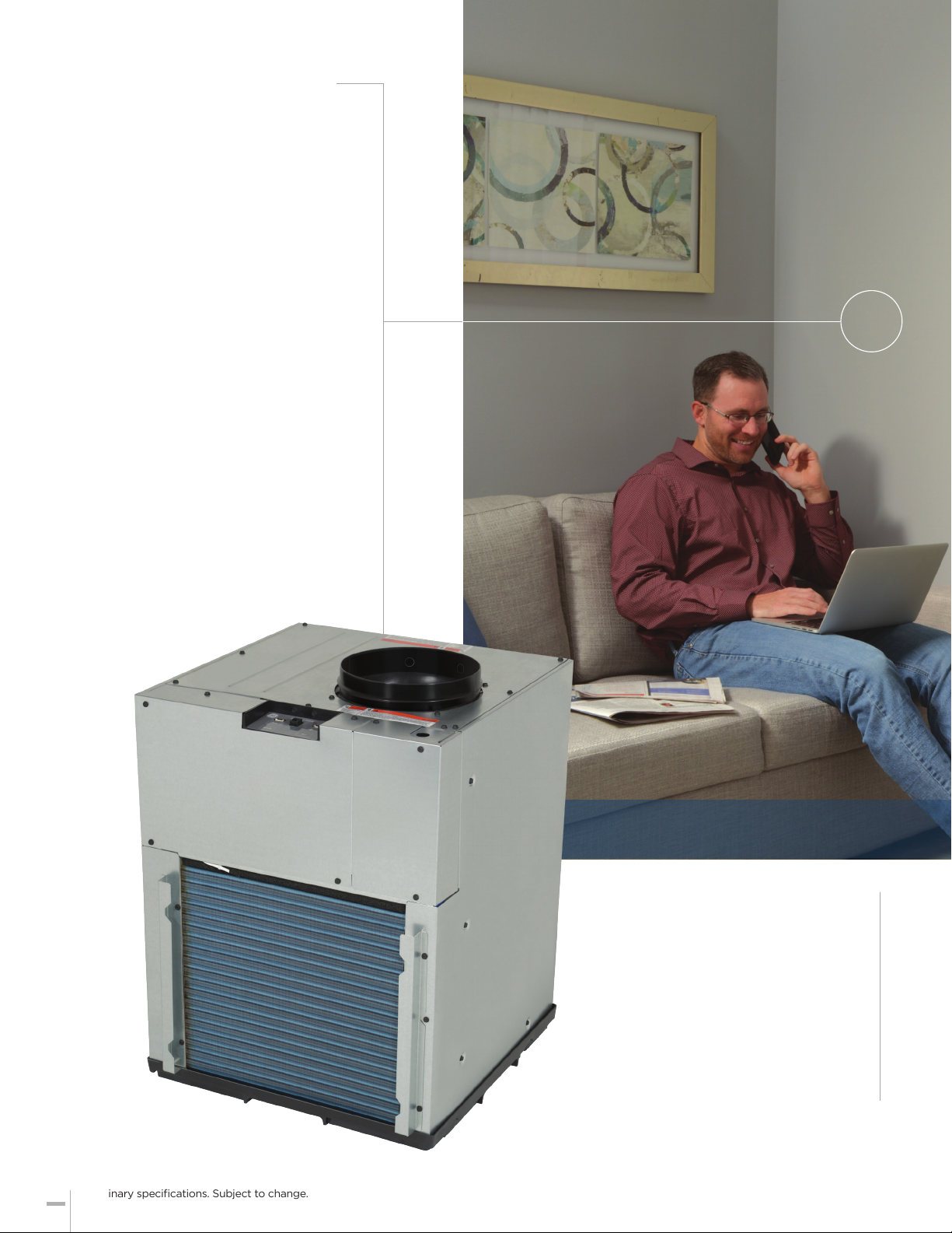
GE Appliances changes the industry
standard for Vertical Air Conditioners.
The Zoneline UltimateV10 Vertical AC
is designed with 10 exclusive features
and innovations that make ownership
simple, ecient and easy!
We provide the ultimate owner experience
by solving design challenges that
others miss.
®
UltimateV10
I
TM
THE ULTIMATE OWNER EXPERIENCE
Preliminary specifications. Subject to change.
2
EXPLORE THE 10 EXCLUSIVE FEATURES
1
Insta-Platform™ *
One-piece design fully
integrates with the wall
plenum and aligns for a
tight seal. Eliminates need
for a customized platform
construction on site
2
Self-Contained
Drainage System*
Easy installation allows
for simple chassis removal
while leaving plumbing
completely intact
Page 3

Fast-Connect Plumbing*
3 5 7 9
Thoughtful design enables
platform build and rough
plumbing completed in
only minutes
Quick-Install Plenum
4 6 8
Plenum is easily installed
from the interior of
building, without the
need for exterior
building access**
Self-Aligning,
Lock-in-Place System
Perfect fit and mistake
proof when the chassis
is placed on the platform
Onboard Diagnostics
Electronic controls give
clear and fast diagnostics
data and fault codes,
for quick and easy
notifications
Reverse Cycle Defrost
Exclusive technology
increases eciency,
enabling the unit to run in
heat pump mode longer
Anti-Corrosion Design
Exclusive rust-proof
basepan and bulkhead
provide another level of
corrosion protection
10
* RAVDPLAT, platform with drain must be ordered separately
**Caulking requires exterior access
Ultra-quiet
Delivers quiet cooling
power with a smooth sound
for a good night’s sleep
SmartHQTM WiFi
Capability
An optional WiFi module
gives property managers
the ability to oversee units,
increasing productivity
and enhancing guests’
experience
Preliminary specifications. Subject to change.
3
Page 4
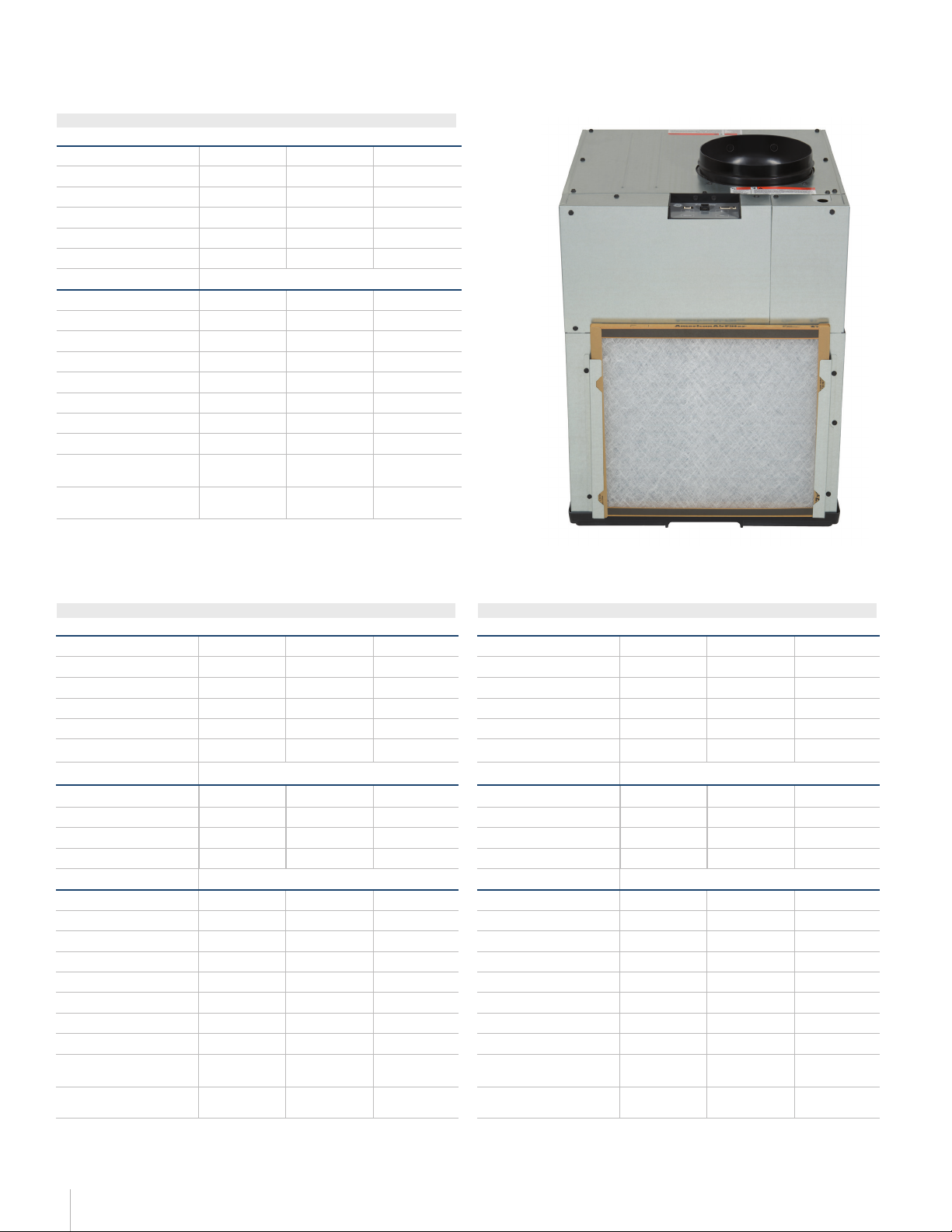
VERTICAL AIR CONDITIONER SPECIFICATIONS
AZ95 SERIES - 230/208V MODELS*
COOLING WITH ELECTRIC HEAT SPECIFICATIONS
AZ95E09DACFeatures AZ95E12DAC AZ95E18DAC
Cooling BTU 9200 11500 17200
EER (Minimum) 11.5 12.1 11.2
Cooling Power (W) 795 940 1520
Cooling Current (A) 3.6 4.3 7. 3
Sensible Heat Ratio (SHR) 74% 73% 70%**
Dehum (Pints per Hour) 2.2 2.8 4.7**
Other
Refrigerant R-410A R-410A R-410A
CFM @ 0.1 ESP (med fan) 408 408 468
CFM @ 0.1 ESP (low fan) 305 356 408
Product Width (in) 23 5/8 23 5/8 23 5/8
Product Depth (in) 24 1/8 24 1/8 24 1/8
Product Height (in) 31 7/8 31 7/8 31 7/8
Product Weight net (lbs) 119 127 141
Packaged Weight gross (lbs) 132 140 154
Clearances for Front Install
(min.)
Clearances for Side Install
(min.)
Note: Preliminary data subject to change
*230V Performance Data Listed
**18K Dehum Rate and SHR data acquired using medium fan speed. All other models
show low fan speed data.
AZ95 SERIES - 230/208V* AZ95 SERIES - 265V
HEAT PUMP WITH BACKUP ELECTRIC HEAT SPECIFICATIONS HEAT PUMP WITH BACKUP ELECTRIC HEAT SPECIFICATIONS
Cooling BTU 8900 11300 17000
EER (Minimum) 11.1 11.8 11.1
Cooling Power (W) 800 955 1525
Cooling Current (A) 3.7 4.5 7.1
Sensible Heat Ratio (SHR) 76% 75% 71%**
Dehum (Pints per Hour) 1.9 2.5 4.4**
Heat Pump
Heating BTU 8500 10500 15800
COP (Minimum) 3.3 3.5 3.3
Heating Power (W) 735 870 1400
Heating Current (A) 3.5 4.3 6.6
Other
Refrigerant R-410A R-410A R-410A
CFM @ 0.1 ESP (med fan) 408 417 468
CFM @ 0.1 ESP (low fan) 305 376 408
Product Width (in) 23 5/8 23 5/8 23 5/8
Product Depth (in) 24 1/8 24 1/8 24 1/8
Product Height (in) 31 7/8 31 7/8 31 7/8
Product Weight net (lbs) 122 128 142
Packaged Weight gross (lbs) 135 141 155
Clearances for Front Install
(min.)
Clearances for Side Install
(min.)
Note: Preliminary data subject to change.
*230V Performance Data Listed
**18K Dehum Rate and SHR data acquired using medium fan speed. All other
models show low fan speed data.
4
3" on all sides 3" on all sides 3" on all sides
5" on front,
3" on sides
AZ95H09DAC AZ95H09EACFeatures FeaturesAZ95H12DAC AZ95H12EACAZ95H18DAC AZ95H18EAC
5" on front,
3" on sides
5" on front,
3" on sides
Cooling BTU 8700 11400 17100
EER (Minimum) 11.0 11.0 11.0
Cooling Power (W) 775 925 1560
Cooling Current (A) 3.0 4.0 6.3
Sensible Heat Ratio (SHR) 75% 76% 75%**
Dehum (Pints per Hour) 1.9 2.5 4.4**
Heat Pump
Heating BTU 8000 10500 15900
COP (Minimum) 3.3 3.3 3.3
Heating Power (W) 660 865 1435
Heating Current (A) 2.8 3.7 5.9
Other
Refrigerant R-410A R-410A R-410A
CFM @ 0.1 ESP (med fan) 408 417 468
CFM @ 0.1 ESP (low fan) 305 376 408
Product Width (in) 23 5/8 23 5/8 23 5/8
Product Depth (in) 24 1/8 24 1/8 24 1/8
Product Height (in) 31 7/8 31 7/8 31 7/8
Product Weight net (lbs) 122 128 142
Packaged Weight gross (lbs) 135 141 155
3" on all sides 3" on all sides 3" on all sides
5" on front,
3" on sides
5" on front,
3" on sides
5" on front,
3" on sides
Clearances for Front Install
(min.)
Clearances for Side Install
(min.)
Note: Preliminary data subject to change.
**18K Dehum Rate and SHR data acquired using medium fan speed. All other
models show low fan speed data.
3" on all sides 3" on all sides 3" on all sides
5" on front,
3" on sides
5" on front,
3" on sides
5" on front,
3" on sides
Page 5
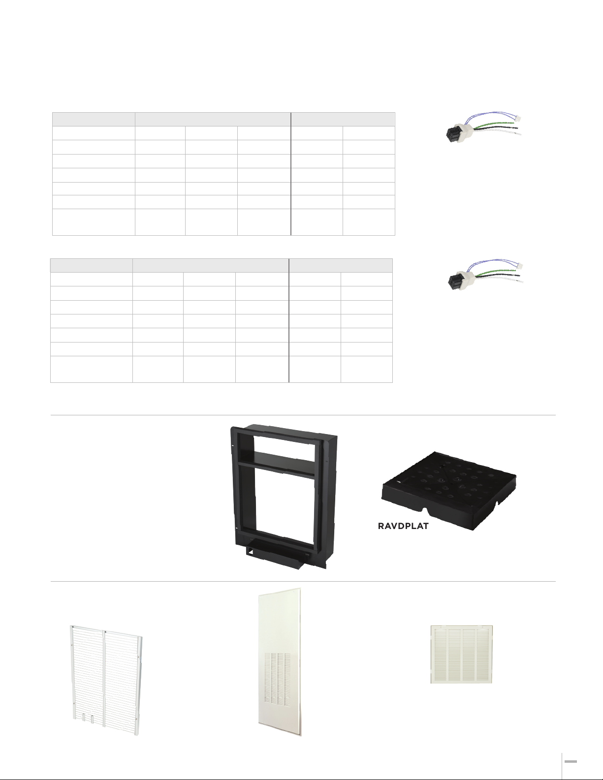
ACCESSORIES
ESSENTIAL ACCESSORIES
Zoneline Vertical Air Conditioners require a set of essential accessories for proper operation. Once you have selected the
size of unit needed, next you’ll need to consider the following:
POWER CONNECTIONS- All AZ95 Zoneline Vertical units must be direct connected
POWER CONNECTION REQUIREMENTS (RESISTANCE HEAT)
230/208 VOLT 9,000/12,000 BTUh 18,000 BTUh
POWER CONNECTION KIT
Heater BTUh 8360/6838 11770/9629 17060/13952 11770/9629 17060/13952
Total Watts 2568/2122 3568/2940 5118/4207 3568/2940 5118/4207
Heater Watts 2450/2004 3450/2822 5000/4089 3450/2822 5000/4089
Total Heating Amps 10.7/9.6 15/13.6 21.7/19.7 15/13.6 21.7/19.7
MCA
Recommend Protective
Device (MOCP)
265 VOLT 9,000/12,000 BTUh
POWER CONNECTION KIT
Heater BTUh 8360 11770 17060 11770 17060
Total Watts 2568 3568 5118 3568 5118
Heater Watts 2450 3450 5000 3450 5000
Total Heating Amps 9.2 13 18.9 13 18.9
MCA 15 20 30 20 30
Recommend Protective
Device (MOCP)
RAK315D RAK320D RAK330D RAK320D RAK330D
15
15 amp
time-delay
fuse or breaker
POWER CONNECTION REQUIREMENTS (RESISTANCE HEAT)
RAK515D RAK520D RAK530D RAK520D RAK530D
15 amp
time-delay
fuse or breaker
20 30 20
20 amp
time-delay
fuse or breaker
20 amp
time-delay
fuse or breaker
30 amp
time-delay
fuse or breaker
30 amp
time-delay
fuse or breaker
20 amp
time-delay
fuse or breaker
18,000 BTUh
20 amp
time-delay
fuse or breaker
30
30 amp
time-delay
fuse or breaker
30 amp
time-delay
fuse or breaker
RAK3 15D/320D/330D
RAK320D shown
230/208-VOLT UNIVERSAL
DIRECT CONNECT
POWER SUPPLY KIT
RAK515D/520D/530D
RAK520D shown
265-VOLT UNIVERSAL
DIRECT CONNECT
POWER SUPPLY KIT
The correct kit for the installation is determined by the voltage and breaker size of the
electrical circuit
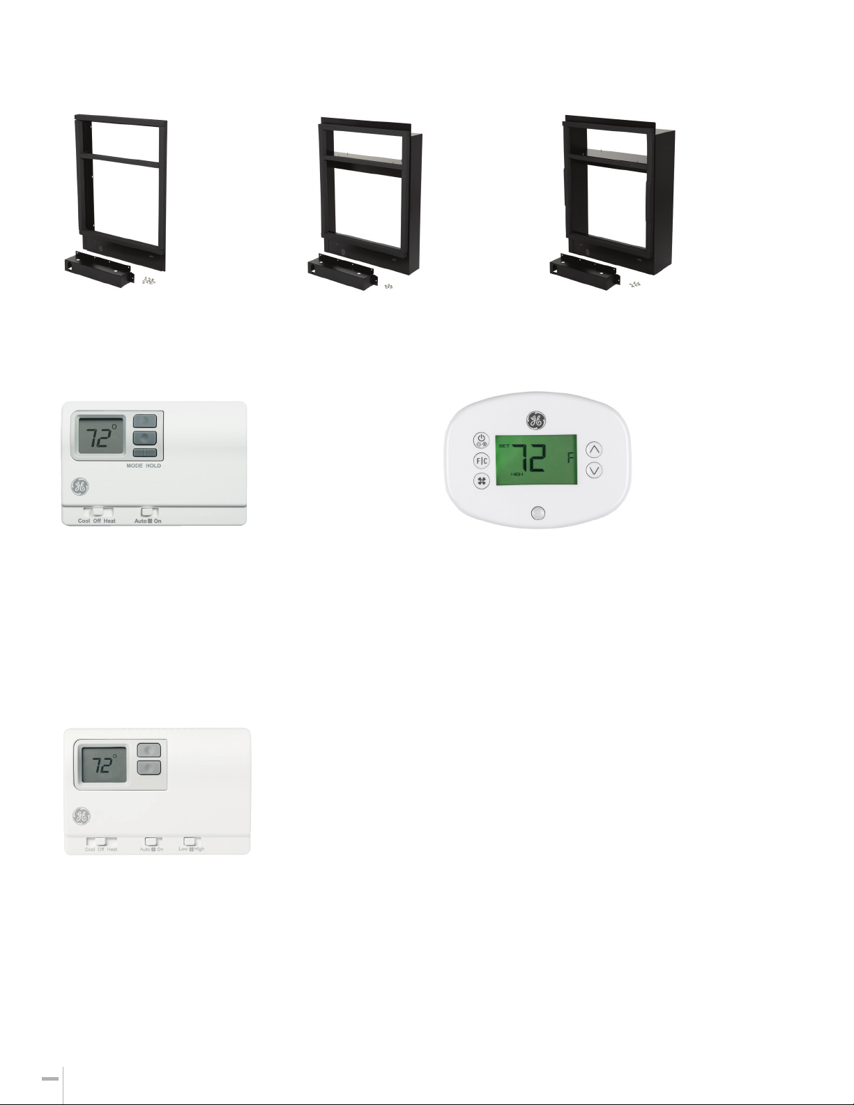
TELESCOPING WALL PLENUM
AND DRAIN PLATFORM
• Available in black
RAVWPT15
Telescoping plenum for
RAVDPLAT
Drain Platform
wall depths 8"-15"
Wall Cut out: 24” x 32”
EXTERIOR GRILLE AND INTERIOR
ACCESS PANELS
ARCHITECTURAL
LOUVER
RAVAL 3
Aluminum
Outdoor Grille
RAVRG4
Access Panel with
Return Air Grille
Cut out:
28-1/8” W x 55-7/8” H
RAVRG2
Return Air Grille
Cut out:
20-3/8” W x 20-3/8” H
Preliminary specifications. Subject to change.
5
Page 6
ACCESSORIES (continued)
PLENUM ADAPTERS
RAVTRANS2
Plenum adapter
to transition from
existing AZ75/
AZ85 wall plenum
to AZ95 unit
RAVTRANS3
Plenum adapter
to transition
from existing
AZ90/AZ91
shallow plenum
(RAVWPT8) to
AZ95 unit
REMOTE THERMOSTATS
All Zoneline Vertical units are compatible with GE Appliances’ wall-mounted remote thermostats.
RAK149P2
HEAT PUMP DIGITAL PROGRAMMABLE
REMOTE THERMOSTAT
• 24V AC digital remote wall thermostat
• Programmable for 7-day or 5+2-day programs
• Requires 5-wire (resistance heat) or 6-wire
(heat pump) hookup
• Works with single-stage cooling and
single-stage or two-stage heating
systems
RAK180W1
ENERGY MANAGEMENT OCCUPANCY
SENSING WIRED/WIRELESS THERMOSTAT
• 2-wire power connection available (all other
signals wireless)
• Thermostat (shown) & control card
(mounts on top of unit) included
• Control card works off 24 Volt AC signal
from unit
• Works with single-stage cooling and
single-stage or two-stage heating systems
with proper set up. Default is two stage
heating and B type heat pump
• Extra 24V output may be programmed to
control other room systems such as lighting,
vents, etc.
RAVTRANS4
Plenum adapter
to transition
from existing
AZ90/AZ91
deep plenum
(RAVWPT14)
to AZ95 unit
RAK149F2
HEAT PUMP DIGITAL TWO FAN SPEED
THERMOSTAT
• Two fan speeds
• 24V AC digital remote wall thermostat
• Requires 6-wire (resistance heat) or
7-wire (heat pump) hookup
• Works with single-stage cooling and
Preliminary specifications. Subject to change.
6
Page 7
ZONELINE UltimateV1 0 AI R
CONDITIONER
SYSTEM FEATURES
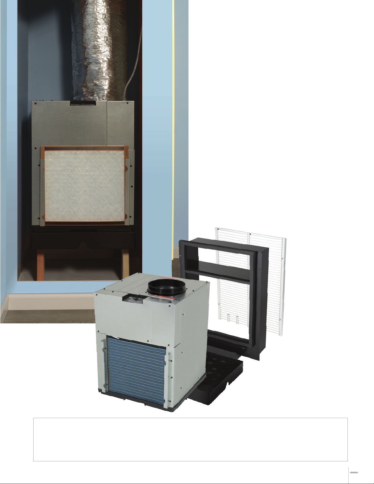
The Zoneline UltimateV10 Single Packaged Vertical air
conditioner is designed with features and innovations
making it the ideal unit to own.
• Excellent efficiency and dehumidification
• Permanently lubricated fan motors
• Standard size air filter (18” x 20” x 1”) included
• Central desk control capability
• HI and LOW fan speeds controlled by remote thermostat
• Corrosion protection treatment standard
• Slinger ring condensate removal
• Indoor frost control
• Automatic compressor random restart
• Compressor restart delay
• Electronic control diagnostics/Service Models
• Warranty (including both parts and labor)
• Boost Heat
• Freeze/Heat Sentinel
• Auxiliary Control Settings
SYSTEM ESSENTIAL
COMPONENTS
• Drain Platform
(RAVDPLAT)
• Wall plenum
• Exterior grille
• Chassis
• Drain connections
• Remote thermostat
• Return air grille
• Ductwork
(field supplied)
• Supply register
(field supplied)
• Access panel
or door
• Platform Legs
(field supplied)
IMPORTANT NOTICE
Equipment used as a primary source for heating or cooling is an integral part of the building in which it is installed.
Proper application is essential for satisfactory performance over a wide range of operating conditions. It is strongly
recommended that a professional engineer determine proper application.
If this unit is a replacement unit, its specifications and performance may differ from those of the unit it is replacing.
For that reason, we again strongly recommend that a professional engineer determine proper application.
Preliminary specifications. Subject to change.
7
Page 8
FEATURES & BENEFITS
EXCELLENT EFFICIENCY
AND DEHUMIDIFICATION
GE Appliances recognizes the importance of energy
efficiency and dehumidification in an air conditioning
system and uses EER (Energy Efficiency Rating) as
the required means of reporting the relative cooling
efficiency of the unit.
The measurement of the efficiency of the heat pump
output, when compared to electric resistance heat,
is called the Coefficient of Performance (COP). The
GE Zoneline single packaged vertical heat pump has
outstanding COP ratings. This number provides a basis
not only for comparing the heat pump output to electric
resistance heat, but also the ability to directly compare
heat pumps within the same range of capacity to
one another.
PERMANENTLY LUBRICATED FAN MOTORS
The Zoneline Vertical chassis has two permanently
lubricated, totally enclosed fan motors. The motors are
permanently lubricated to reduce maintenance, and
totally enclosed to keep dirt and water out of the
motor windings.
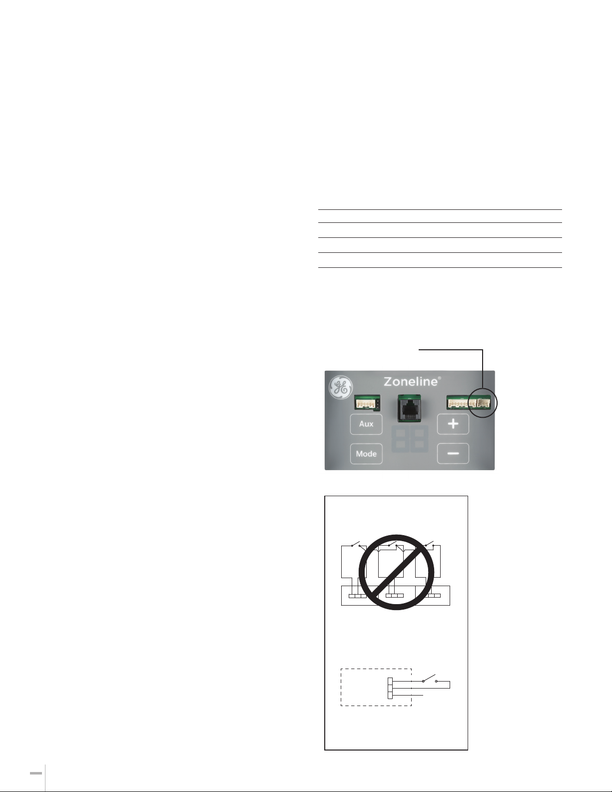
CENTRAL DESK CONTROL (CDC)
AZ95 units are compatible with simple on/off 2-wire
Central Desk Control (CDC) systems. The unit utilizes a
3 pin port to interface such a system. This requires the
separate purchase of the RAKCDC connector accessory.
The most common installation of this type of system is a
switch mounted at the registration desk; and, upon guest
check-in, the switch is activated to allow the air conditioner
to operate.
Likewise, when the guest checks out, the device is switched
to the “OFF” setting so the unit will not operate when the
room is not rented.
In some resort areas, this feature is usually used with a
normally open switch connected to sliding glass doors,
and opening the doors causes a contact to close, turning
the air conditioner off. This prevents the unit from running
and wasting energy with the sliding glass door open.
IMPORTANT CDC NOTES:
1. The unit requires the use of a normally open switch.
Closing the circuit shuts off the system.
2. Both wires comprising the circuit must connect to the
CDC terminals on the unit and to the controlling switch.
Do not use a common buss (at the unit or at the switch
panel) in the wiring.
3. A 24-volt transformer is contained within the Zoneline
Vertical Unit. No external voltage may be applied to
the unit through the CDC terminals.
4. Minimum wire size for CDC wiring:
WIRE SIZE # AWG MAXIMUM ALLOWABLE LENGTH
#22 600 Ft.
#20 900 Ft.
#18 1,500 Ft.
#16 2,000 Ft.
5. Freeze Sentinel and Heat Sentinel still remain
operational when the unit is connected to a
CDC system.
CDC PORT LOCATION
RAKCDC PORT
EXAMPLE OF COMMON BUSING
RAKCDC
NOT PERMITTED
CDC Typical Wiring
Preliminary specifications. Subject to change.
8
INCORRECT COMMON BUSING
NORMALLY OPEN SWITCH=
UNIT OPERATIONAL
FIELD SUPPLIED
CDC SWITCH
RAKCDC
CONNECTOR
(sold separately)
(Wiring from RAKCDC connector to
field devices is field supplied)
POWER RED
CDC BLUE
E. FAN YELLOW
TYPICAL WIRING
Page 9
FEATURES & BENEFITS
TRANSFER FAN INTERFACE
The advantage of the Zoneline Vertical chassis product
is the ability to duct air to other rooms. If it is desired to
move air into a space where there is no ducting, a 24 VAC
connector (RAKCDC) is available to operate a relay that
controls a wall mounted fan that transfers air from one
room to another. With this, the wall mounted fan would
turn on whenever the indoor fan of the unit operates.
While the 24-volt control signal comes from the
Zoneline® Vertical chassis, the electrical power for the
operation of the transfer fan itself is NOT provided by
the Zoneline Vertical chassis.
Transfer fans and their controlling relays, power and wiring
are field supplied.
2-SPEED INDOOR FAN MOTOR
FOR SELECTABLE HIGH AND LOW SPEEDS
Since the Zoneline Vertical chassis discharge air may be
routed through duct work for air distribution into one or
more rooms, the units are equipped with a 2-speed fan
that provides greater air movement to compensate for
the additional duct length. GE Appliances recommends
an HVAC engineer be consulted to determine the best
fan speed for the application.
Higher CFMs tend to increase the operating sound level,
both from fan noise and from the air noise in the duct.
Higher CFMs also reduce the dehumidification rate of
the unit, while lower CFMs provide quieter operation
and better dehumidification. However, if the CFMs are
not high enough to adequately move the air through
the duct system, the unit will not be able to provide
a comfortable room.
If the Zoneline Vertical chassis is connected to a wall
thermostat without the ability to provide two fan speeds,
the fan speed will be determined by connecting the wire
controlling the fan to the low speed fan terminal or the
high speed fan terminal on the unit.
CORROSION PROTECTION
TREATMENT—STANDARD
All Z
oneline Vertical chassis
protected against damage from
seacoast area corrosion. Components
that are in contact with the salt air have
special coatings or are made of noncorroding materials to help withstand
the corrosive effects of the environment.
This protection includes the use of
totally enclosed outdoor fan motors with
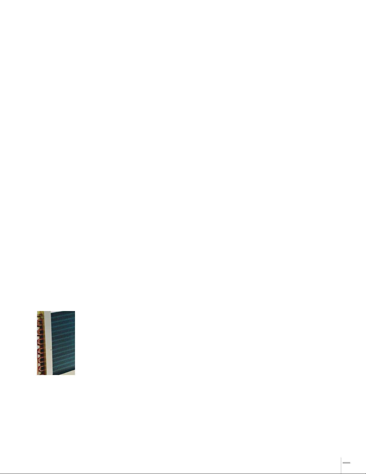
painted casings and a special coating on the outdoor coil
to extend the life of the unit in a coastal environment.
The base pan is made of durable non-corrosive plastic.
are
INDOOR COIL FROST CONTROL
Under certain operating conditions, frost can form on
the indoor coil of an air conditioner, reducing air flow
and cooling. In order to prevent frost from forming, the
Zoneline Vertical chassis has an automatic frost control
on the indoor coil. When frost begins to form on the coil,
the compressor stops while the indoor fan continues to
run, until the coil temperature increases and the frost
dissipates.
At that time, the compressor resumes operation and
cooling continues. The indoor fan remains running during
the time the compressor is off to help warm the coil with
room temperature air.
AUTOMATIC COMPRESSOR RANDOM RESTART
In the event of a power interruption, all compressors
attempting to restart immediately when power is
restored can result in a power surge that can cause
another power failure. The microprocessor in the
Zoneline Vertical chassis has a random restart logic
system that prevents all compressors from restarting
at the same instant.
COMPRESSOR RESTART DELAY
Zoneline Vertical units are designed to provide
a minimum of three minutes of compressor off time
to allow refrigerant pressures to equalize before
attempting to restart. Attempting to restart against
a high head pressure shortens compressor and
overload protector life.
The units are also designed to provide a minimum of
three minutes of compressor run time to prevent short
cycling from disturbing the room occupant.
FREEZE SENTINEL
• Detects low room temperature and turns heater to
help protect against damage caused by freezing
room temperatures.
• The electric heater turns on at 41o F and warms the
room up to 46o F and shuts off.
• Freeze Sentinel may by turned off via the
auxilliary control.
HEAT SENTINEL
The property owner may choose to activate the Heat
Sentinel feature on the Zoneline unit. If the Heat Sentinel
is activated and room temperature reaches 85o F
(even when the unit is in the “OFF” mode), the unit will
automatically start the air conditioning operation and will
shut off when the room temperature reaches 80o F.
This will help dehumidify the air and lower high
temperatures so the guest will not be entering an
extremely hot room.
SLINGER RING CONDENSATE REMOVAL
Condensate water removed from the indoor air is
dispersed into the air stream by the outdoor fan slinger
ring and deposited on the hot outdoor coil. The water
helps cool the refrigerant in the outdoor coil and
increases the efficiency of the air conditioner, while
reducing the condensate draining from the unit.
Preliminary specifications. Subject to change.
9
Page 10

FEATURES & BENEFITS
HEAT PUMP OPERATION
Heat pumps save money compared to electric
resistance heat, but if the unit cannot provide room
occupant comfort, the savings may be of questionable
benefit. GE Appliances has years of experience with
designing Zoneline heat pumps to solve the problem
of guest complaints.
The heat pump unit uses a two-stage heat/one-stage
cooling thermostat. Stage one, heat pump operation,
will operate as specified by the remote thermostat being
used as long as outdoor conditions will allow. If the
remote thermostat asks for heat pump heating outside
of unit heat pump operating conditions, the heating
request will be met by utilizing back-up resistance heat.
The Z
oneline Vertical chassis
will operate in efficient heat
pump mode down to a 25°F outdoor temperature.
At temperatures below this, the unit will automatically
switch to electric heat.
The resistance heater and the heat pump do not operate
simultaneously.
HEAT PUMP LOGIC
The chart below indicates the standard heating source
of the AZ95 series heat pump models under various
outdoor conditions. The unit is designed to provide heat
pump saving without sacrificing room comfort.
Heat Setting Configuration
All Electric
Heat Mode
(Aux Mode 8)
OFF
OFF
ON
*Simultaneous supplemental heat (Boost Heat): 1.0kW @ 230V & 265V;
0.8kW @ 208V
Heat Boost
Mode
(Aux Mode 9)
OFF
ON
OFF/ON
Full Resistance
Full Resistance
Full Resistance
Outdoor Temperature
Above 85oF
Heat
Heat
Heat
Between 85oF
and 25oF
Heat Pump
Heat Pump +
Supplemental
Heater*
Full Resistance
Heat
Below 25oF
Full Resistance
Heat
Full Resistance
Heat
Full Resistance
Heat
QUICK HEAT RECOVERY
Unit software will provide electric resistance heating as
the first heat cycle following the unit having been set to
either off or cool on the remote thermostat. This ensures
occupant comfort by quickly reaching the desired
setpoint temperature. All subsequent heating cycles will
follow heat staging as dictated by the remote thermostat
if required outdoor temperature conditions are met.
Quick heat recovery is not influenced by heat pump logic.
HEAT PUMP DEFROST
Zoneline heat pumps utilize a reverse-cycle, demanddefrost system to extend heat pump operation and
increase savings from extended operation. The
microprocessor determines the need for defrosting from
criteria based on continuous compressor running time,
outdoor air temperature and outdoor coil temperature.
When defrosting is required, the unit reverses the flow of
refrigerant to direct the hot gas into the outdoor coil to
melt the frost buildup.
Before and after the reverse-cycle defrost, the unit shuts
off the compressor to allow the refrigerant pressures to
equalize through the system. During these periods of
pressure equalization, the full resistance heat capacity
of the unit is activated to help ensure room comfort
conditions during the defrost cycle. The unit remains in
the defrost cycle for a minimum of three minutes and
up to a maximum of nine minutes. The defrost cycle
terminates when the outdoor coil reaches a temperature
of 68o F or the maximum time has been reached.
BOOST HEAT
The AZ95 series offers a Boost Heat option feature that
utilizes partial supplemental resistance heat at the same
time as the heat pump operation. The boost heat feature
changes stage one heating (heat pump) to be heat pump
with partial resistance heat. Stage two heating stays as
full resistance heat.
NOTE: Heat Pump and full resistance heat shall never be
on at the same time.
ELECTRONIC CONTROL DIAGNOSTICS/
SERVICE MODE
The Zoneline Vertical system continuously monitors the
unit operation and in some cases the unit may take action
and shut down until conditions are corrected.
The electronic control will store/provide Error Codes
to aid in diagnosis and correction to get the unit up
and running quickly.
In addition to error codes, the unit is equipped with
Service Modes that allow for independent testing of unit
functionality. This allows for fan, heat, cool operations
among other checks to be “forced” without signals from
the remote thermostat or unit temperature sensors. This
is a valuable tool that helps pinpoint operational problems
and also helps distinguish unit malfunction from problems
caused by remote thermostat.
See the product Use & Care/Mini-Manual for specifics on
Error Codes, Service Modes, and how to use the system.
Preliminary specifications. Subject to change.
10
Page 11
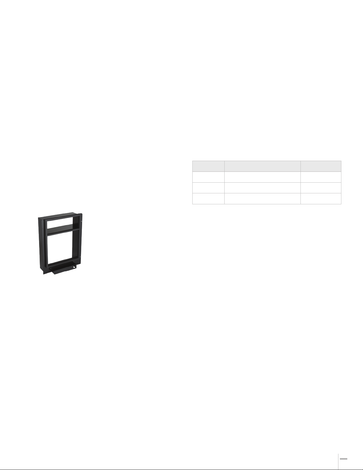
COMPONENTS & INSTALLATION
Each Zoneline single packaged vertical unit requires
a drain platform, wall plenum, exterior grille, unit, remote
thermostat, filter and a return air grille, ductwork and
supply registers.
The drain platform legs, ductwork and supply registers
are field supplied. Each of the other components is
ordered separately. The drain platform, wall plenum and
exterior grille are specifically designed to interface with
the GE Appliances Zoneline Vertical chassis and must be
purchased from the same source as the unit. Custom
exterior grilles may be used but must comply with the
requirements shown on page 12.
The remote thermostat and the return air grille are
offered as accessories by GE Appliances, but may be
purchased from a source other than GE Appliances.
If a non-GE Appliances thermostat is being used,
it should meet the general thermostat requirements
mentioned on page 14. Any custom return air grille
being used should offer a louvered area as large as the
GE Appliance offering or larger.
WALL PLENUM
Since the unit itself does not install in the wall opening,
the use of a plenum is necessary to contain and separate
the outdoor air paths. The plenum must be able to
hold water in the bottom without
leaking into the wall cavity. It also
must have a “splitter” to separate
the outdoor air paths and prevent
the discharge air from being drawn
back into the unit.
The wall plenum is the first
component to be installed.
GE Appliances model RAVWPT15
is available for use with wall
thicknesses of 8” to 15.”
The plenum is to be installed square and level in the
opening and secured to the wall construction with
screws or nails in the sides located a minimum of 2" up
from the bottom of the plenum. No nails or screws may
be used in the bottom or top of the plenum to prevent
water entering the wall cavity.
The plenum is not load bearing, so a proper header
needs to be installed above the plenum the same as
over any window opening in the wall. If the building
construction is brick, concrete block or other non selfsupporting material, a lintel must be installed over the
plenum opening. The plenum must be caulked to the
wall, both to the outdoor wall face and to the interior
wall, along all four sides to prevent air and water
infiltration.
WALL PLENUM MODELS:
RAVWPT15-For installations with walls 8” to 15” thick.
REPLACEMENT OF OLDER GE VERTICAL
PRODUCT
When replacing a previous model GE Appliances Vertical
Unit with a new AZ95 series vertical air conditioner, one
of three transition plenums must be used.
Differences in chassis designs between the prior
models and AZ95 series require careful installation and
planning. Changes in drain exit locations, drain routing,
electrical connections, platform height, conditioned air
duct location and additional space requirements for
installation of a transition kit are all items that need to
be considered when replacing a prior model with an
AZ95 series unit.
The selection of the appropriate transition kit is based
on the original wall plenum being used. If a RAVTRANS
kit is already being used to transition an original wall
plenum to an AZ90/91 series, it will need to be removed
and a RAVTRANS2 kit will need to be installed prior
to installing an AZ95 series unit. Please reference the
following chart to determine which transition kit is
needed. Before starting the conversion, be sure there
is adequate closet space to meet the manufacturers
recommend minimum clearance requirements.
Transition Kit
Model
RAVTRANS2
RAVTRANS3
RAVTRANS4
NOTE: For AZ90/91 model replacement, make sure no
existing RAVTRANS kit is being used. If so, discard and use
RAVTRANS2
AZ75/85 Series (used a beige color plenum)
AZ90/91 Series RAVWPT14 plenum ONLY
Transition From
AZ90/91 Series RAVWPT8 plenum ONLY
(black, 5.5”-8” deep)
(black, 8”-14” deep)
Additional Closet
Clearance For Kit
1.5”
N/A
N/A
DRAIN PLATFORM
The AZ95 Series requires the use of a separate drain
platform accessory (RAVDPLAT). This accessory
supports the chassis and positions it properly to seal to
the wall plenum. Secondly, it serves as the drain pan for
the chassis with connections for both a primary and
secondary drain. This innovative accessory saves time
and money by eliminating the need for field fabricated
support platforms. It also greatly simplifies chassis
removal from the closet because the plumbing
connections are made to the platform as opposed to the
chassis itself.
The drain platform height is determined based on the
position of the RAVWPT15 wall plenum. The bottom
edge of the drain platform is flush with the bottom edge
of the wall plenum. Technically, the bottom edge could
be set to floor level, but that would likely make
connecting to a building drain system difficult. In most
installations, it will be desired to raise the platform
several inches off the floor. This can easily be done using
2”x4” lumber cut to length and positioned in the
integrated support pockets of the RAVDPLAT. Only two
support legs are needed as the exterior side is supported
by the wall plenum.
The primary drain can be directed out either side or the
front of the drain platform through sidewall notches in
the platform. If the platform is elevated for drainpipe
clearance below, the primary drain can run any direction
desired. The secondary drain is to be piped through the
wall plenum to the exterior of the building.
For further detail, please see the RAVDPLAT Installation
Instructions.
Preliminary specifications. Subject to change.
11
Page 12
COMPONENTS & INSTALLATION
STANDARD SIZE AIR FILTER
A number of filters, providing varying degrees of
filtering efficiency, are available on the market today.
GE Appliances has designed the Zoneline Vertical
chassis to accommodate a number of filter placement
options. The filter provided with the unit is a standard
size 18" W x 20" H x 1" D filter.
The unit must not be operated without a filter in place,
even during construction.
GE Appliances provides three filter placement options
for design and installation flexibility. Filter brackets are
provided on the front of the Zoneline vertical unit chassis
(18" x 20" x 1"), which allows for the filter to be directly
mounted to the unit.
An access panel, accessory model number RAVRG4,
for the closet enclosure is the second filter placement
option (20”x24”x1 to 2”). The access panel requires a
cutout in the unit closet enclosure wall and provides
access to the unit for servicing and removal. The access
panel should be located in the wall such that the
centerline of the access panel matches the centerline
of the chassis. The bottom of the access panel should
be at least 1" below the top edge of the drain platform
to allow for easy removal of the Zoneline Vertical Unit.
The third filter placement option is incorporated in a
return air grille-RAVRG2. A 20” x 20” x 1” filter fits inside
the grille. The RAVRG2 can be installed in a solid closet
access door or in a closet side wall. A 20 3/8” x 20 3/8”
cutout in the closet wall or door is required to install
this option.
A different size filter may also be used in a field-supplied
frame installed in a return air grille mounted in the closet
enclosure door or wall.
Only one filter is to be used in the installation.
Multiple filters will reduce the air flow and affect unit
performance. A clean filter is essential to efficient unit
operation.
The filter should be checked at least every 30 days and
replaced if dirty.
EXTERIOR GRILLE
The architectural louver exterior grille
is mounted to the exterior of the
plenum and held in place with four
screws inserted from inside enclosure
closet. The grille is designed specifically
for use with the Zoneline Vertical
chassis, and the use of any other grille
must be approved by GE Appliances
Air Conditioning Applications
Engineering.
Small or minor obstacles, such as poles or small shrubs,
should be a minimum of two feet away (radius in all
directions). Larger obstructions, such as a solid fence/
wall and heat generating sources, like a condensing unit,
should be kept away a minimum distance of six feet.
EXTERIOR ARCHITECTURAL TREATMENTS AND
SPECIAL OUTDOOR GRILLES
The architectural design of a building may dictate the
use of special or oversized louvers for aesthetic reasons.
Louvers other than standard Zoneline exterior grilles
may be used on the Zoneline unit, however, these special
louvers, or any special exterior architectural treatments of
the building facade that may restrict the free circulation
of condenser airflow, should be referred to GE Appliances
Application Engineering for evaluation and approval. The
following guidelines should be followed in selecting
a louver:
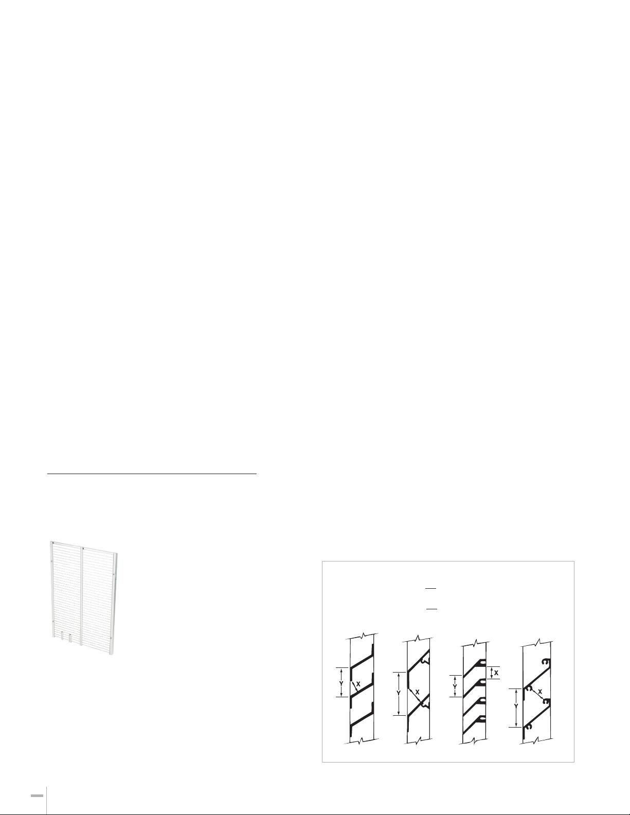
1. The louver must have a minimum of 65% free area.
ASHRAE defines "free area" as the minimum area of
the opening in an air inlet or outlet through which air
can pass. Percent (%) free area equals the X dimension
divided by the Y dimension. (See examples below).
2. The louver should be attached to the wall case in
a manner that will prevent recirculation of condenser
discharge air into the air inlet. If the louver is not
attached directly to the wall case, a field-supplied
splitter or gasket is required between the chassis
and the louver to prevent recirculation.
It is important that the above criteria be followed since
a louver that is too restrictive or allows recirculation will
reduce the unit’s capacity and efficiency, increase the
electrical current draw, cause intermittent operation
due to the compressor overload protector shutting the
compressor off, and cause failure of the compressor
overload protector and shorten compressor life. Using
the unit with a grille that is too restrictive or allows
recirculation may constitute improper installation and will
void the unit's warranty. Since the Zoneline unit complies
with Underwriters Laboratories® requirements, it may be
necessary to send a full size sample louver section to an
independent lab to be tested with the Zoneline unit.
SAMPLE CALCULATIONS
Free Area (%) =
F.A. % =
x
x 100 x = 1" y = 1.5"
y
1
x 100 = 66.7%
1.5
OUTDOOR CLEARANCES
Since the GE Zoneline Vertical chassis is an air exchange
system, it is critical that the exterior grille, which provides
both intake and exhaust, not be covered or impeded
in anyway.
Preliminary specifications. Subject to change.
12
Page 13
COMPONENTS & INSTALLATION
UNIT AND INSTALLATION NOTES
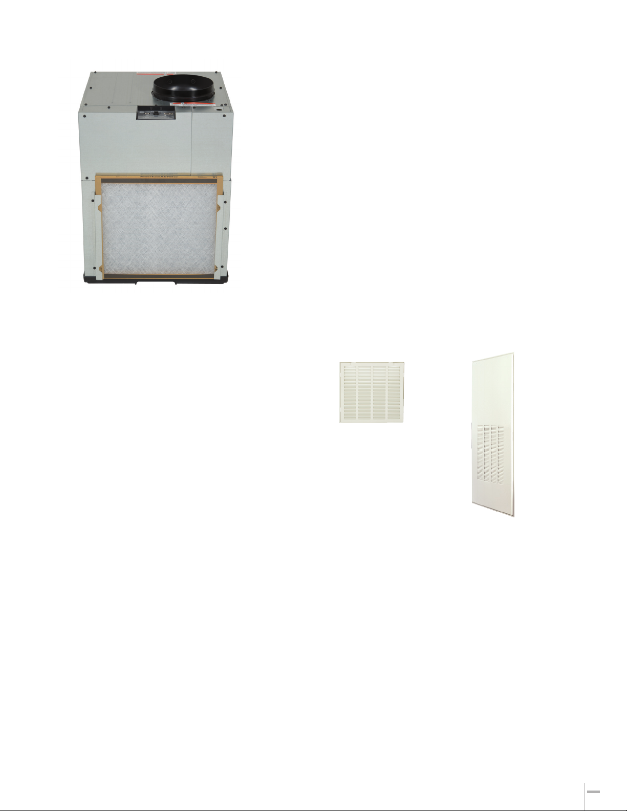
The unit is a one-piece package system that fits
directly into a closet enclosure. Once the drain platform
(RAVDPLAT) has been installed, the chassis can be
positioned on the drain platform and pushed towards
the exterior wall. The chassis will drop down slightly
into the platform, securing it in place and engaging
the gasket on the wall plenum (RAVWPT15). Power,
thermostat, and duct connections can then be made.
A 10" diameter flange on the top of the unit is used to
connect to field-supplied, insulated, flexible or rigid
transition duct with an adjustable ring clamp.
Flexible duct may be used for transitions only. Rigid
duct must be used for 90-degree bends and tees.
Do not use flexible duct for unsupported runs of five
feet or more.
RETURN AIR GRILLE, ACCESS PANEL
OR LOUVERED CLOSET DOOR
The return air from the room to the unit may enter the
closet through one of four ways.
A louvered door may be installed on the closet to allow
return air to enter. When a louvered door is used, the
filter would be installed in the filter bracket on the front
panel of the unit.
A wall-mounted access panel may be used instead of a
louvered door. The return air is through the access panel,
model RAVRG4, which requires a 28 1/8" W x 55 7/8" H
cutout in the wall, and there is a filter bracket behind the
grille louvers.
A return air grille, model RAVRG2, may also be used
and is designed to be installed in a 20-3/8" by 20-3/8"
cutout in a flush closet door or closet sidewall. In
this installation, a filter can fit into the bracket in the
RAVRG2.
A field-supplied return air grille, with a minimum
dimension of 20" W x 20" H, may be used if mounted
in a cutout in the door or wall. When employing this
method for return air, the filter is installed in the bracket
mounted on the unit.
RAVRG2 RAVRG4
POWER CONNECTION KIT
All AZ95 Series Vertical Units are equipped with
universal heaters that are capable of different heater
outputs. Heater output is determined by which unique
direct connect power kit is being used. This increases
the flexibility of a chassis where various heating
requirements may need to be met at a site. This power
connection is the only means of supplying power to the
AZ95 chassis. Please reference the chart on page 5 to
determine the appropriate power connection kit for
your project.
Preliminary specifications. Subject to change.
13
Page 14
COMPONENTS & INSTALLATION
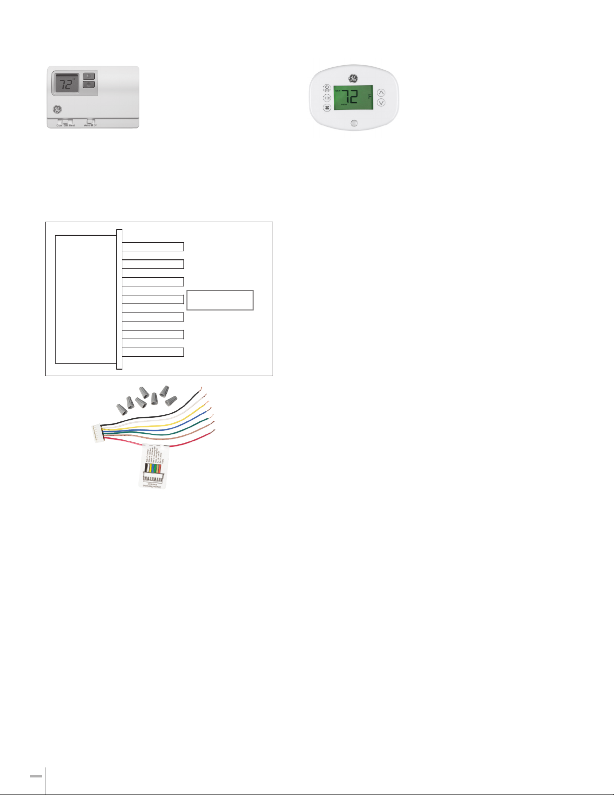
Black -C- Common
White -W- AUXHeat
Yellow -Y-Compressor
Blue -not used
on AZ45 Series
Green -GH- HighFan
Tan -GL- LowFan
Red -R- 24VAC
REMOTE THERMOSTAT
Z
oneline Vertical units
controlled by a wall-mounted
thermostat. GE Appliances offers
a complete line of thermostats to
interface with the units, or most
24-VAC thermostats may be used.
Low voltage wiring connections are made to the 8 pin
harness included with each unit. This harness allows for
a single point thermostat connection to simplify chassis
removal and reinstallation. See diagram below for terminal
designations.
THERMOSTAT WIRING DIAGRAM
Black-C-Common
White-W-AUXHeat
Yellow-Y-Compressor
BLUE-Not used on
AZ95E models
Green-GH-HighFan
Tan-GL-LowFan
Red-R-24VAC
Thermostat Harness
If a non-GE Appliances thermostat is used, the
compatibility of the thermostat with the unit is the
responsibility of the installer. The unit has an integral
transformer, and no external voltage or transformer
may be used.
Maximum wiring length and wire size: AWG 18 up to 66
feet—AWG 20 up to 66 feet; AWG 24 up to 40 feet.
are
ENERGY MANAGEMENT
RAK180W1 universal thermostat
that provides occupancy sensing
energy management.
The thermostat works on single-stage or two-stage
heating systems and operates on a DC or AC signal.
The energy management setup can work on a room by
room basis or it can be upgraded with a network controller
for full site management.
Power to the thermostat can be via batteries or a two-wire
connection from the Zoneline Vertical chassis. Command
control signals are all conducted via wireless communication.
For proper wireless communication, the transmitter control
card must be located on top of the Zoneline Vertical chassis
and NOT inside the metal cover.
GE Appliances also oers the
DUCTWORK & SUPPLY REGISTERS—
FIELD SUPPLIED
Ductwork and supply registers are mentioned here as
System Essential Components, because they are necessary
to complete the installation. These components are field
supplied per the HVAC engineer’s design.
ELECTRICAL INFORMATION—GENERAL
Zoneline Single Packaged Vertical Air Conditioners are
to be connected to a single-phase 60 hertz power. Units
with the voltage designator “D” in the 8th character of the
model number may be operated on either nominal 230-volt
or 208-volt power. Units with the voltage designator “E” in
the 8th character of the model number are to be operated
on nominal 265-volt power (A.K.A. 277-volt power). For all
installations, feeder, sub-feeder, branch circuit and electrical
protective devices must conform to all local codes. In the
absence of a local code, the National Electrical Code should
be followed.
Each unit should be installed on a single branch circuit.
More than one unit per branch circuit is not recommended.
All wiring, must conform to local electrical regulations and
codes. When in doubt, consult the National Electrical Code.
Preliminary specifications. Subject to change.
14
Page 15
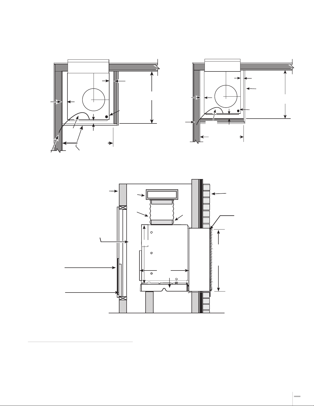
TYPICAL UTILITY CLOSET AND DIMENSIONS (FOR REFERENCE ONLY)
3”
minimum
clearance
Top View
Thermostat
Connection
FRONT INSTALL
Architectural Louver
10”
Duct
13½”
7.16”
Unit
Front
3” minimum
minimum
29 ⅝”
Door/access panel return air grille
Note: It is recommended to leave additional
space around the unit to ease installation
and access for service.
3” minimum
clearance
Electrical
Connection
27 ¾”
minimum
Side View
Top View
3”
minimum
clearance
Thermostat
Connection
SIDE INSTALL
Architectural Louver
10”
Duct
13½”
7.16”
Unit
5” minimum
Front
clearance
minimum
29 ⅝”
3” minimum
clearance
Door/access
panel
29 ¾”
minimum
Electrical
Connection
Inside wall
NOITALLATSNI TNORF •
– 3" minimum clearance from
front of case and 3” minimum
from two sides.
NOITALLATSNI EDIS •
– 5” minimum clearance from
front of case, 3” minimum from
access side and 3” minimum
from non access side.
Option 1
Return air grille
RAVRG2*
(used with field
supplied closet door)
Option 2
Access panel with
return air grille
RAVRG4*
*All variations beginning with this model number
Rigid
ductwork
Flexible or
rigid duct
30”
Drain fittings
Air
discharge
outlet
Unit
Filter bracket
241/8”
3
Secure
Drain Platform
Outside wall
Field supplied
flashing
Wall
plenum
Plenum
cutout
32” H
Exterior/Outside
x 24” W
⁄4”
AVAILABLE ACCESSORIES
• Drain Platform-RAVDPLAT
• Architectural Louver—RAVAL3
• Wall Plenum—RAVWPT15—telescopes from 8” to 15”
• Access Panel with Return Air Grille—RAVRG4
• Return Air Grille—RAVRG2
• Wall Thermostat
Preliminary specifications. Subject to change.
15
Page 16
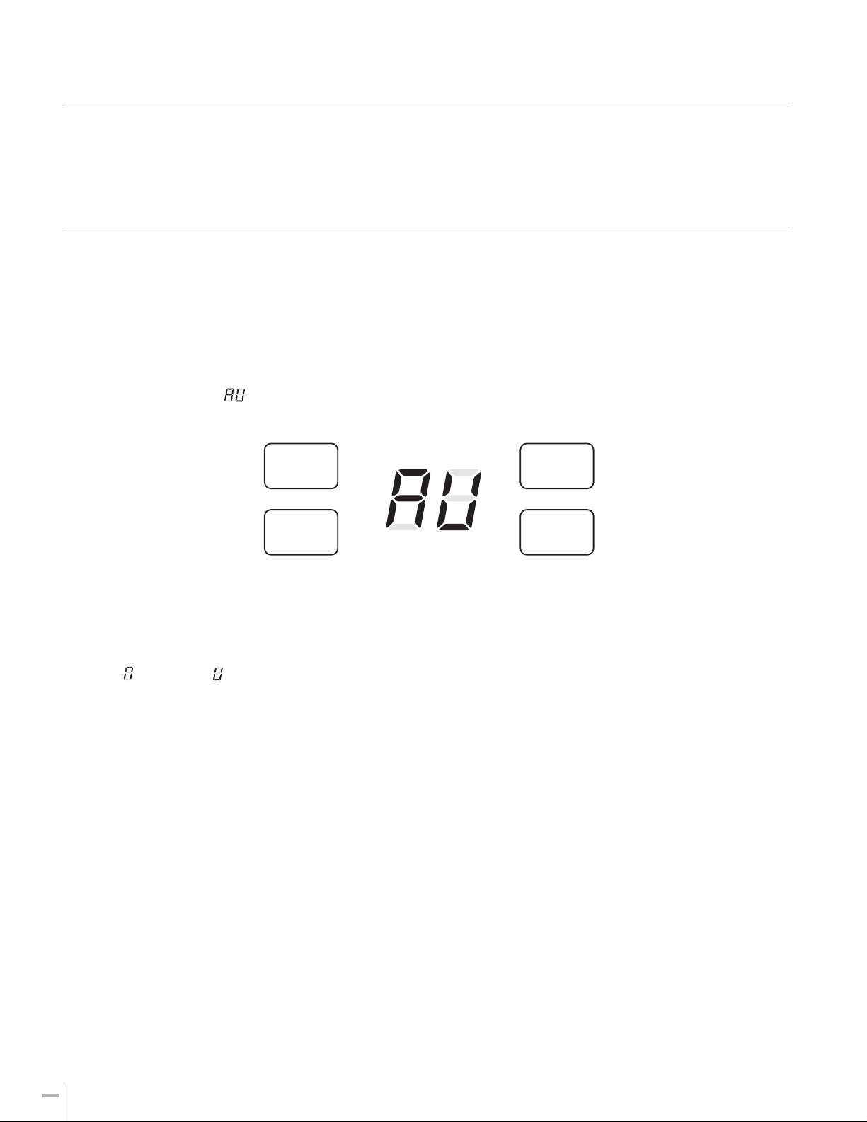
AUXILIARY CONTROLS
SETTING THE AUXILIARY CONTROL
Auxiliary Controls-Aux Set Button
The electronic control for the unit comes preset from the factory to control the unit how “most” customers would
prefer the unit to operate. The presets (called modes or functions) can be modified to accommodate for differences
in installation parameters or personal preferences on how the unit should operate and perform.
If the owner modifies the auxiliary controls it is then the owner that is responsible for ensuring the auxiliary controls
are set to the desired function.
Modes of the Auxiliary Control
Mode 1 – Not Applicable
Mode 2 – Not Applicable
Mode 3 – Freeze Sentinel/Heat Sentinel
Mode 4 – Constant ON Fan
Mode 5 – Not Applicable
To change operating or set up parameters the control must be in AUX Mode. With power applied to the unit, press the
AUX SET button until the “ “ appears on the display.
The display will look like this when entering the AUX Mode :
Aux
Set
Mode 6 – Not Applicable
Mode 7 – Fan Boost Mode
Mode 8 – All Electric Heat (AZ95H only)
Mode 9 – Heat Boost (AZ95H only)
+
Mode
Auxiliary Set Mode
While in AUX Mode, press the MODE button to scroll through the dierent modes. Continue the press the
MODE button until the number corresponding to the mode to be modified is showing in the first digit of the display.
Once the correct number is displayed, use the +/- buttons to change the second digit of the display for that mode
to either “ “ for On OR “ “ for O depending on the desired function.
When the selection for a given mode is complete press the MODE button to continue setting other auxiliary control
functions OR press the AUX SET button to confirm the selection and exit AUX SET mode.
–
Preliminary specifications. Subject to change.
16
Page 17
AUXILIARY CONTROLS
SETTING THE AUXILIARY CONTROL
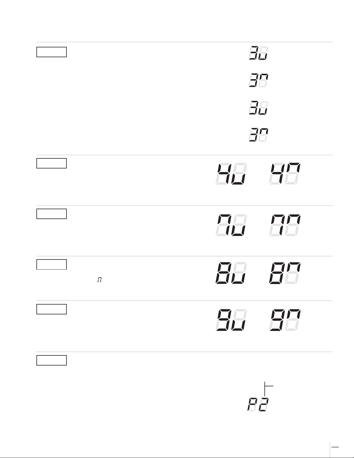
Mode 3
With power to the unit and Freeze Sentinel activated,
the unit automatically provides heat without user interface.
This prevents potential plumbing damage by turning the
heater and indoor fan ON at 41o F and then OFF once the
room temperature reaches 46o F.
When Heat Sentinel is activated, the unit automatically
provides cooling without user interface. This prevents an
excessively hot room by turning the air conditioner ON
at 85o F and then OFF once the room temperature
reaches 80o F.
In the default setting for Mode 3, Heat Sentinel is o,
Freeze Sentinel is on.
NOTE: Note: Heat Sentinel is the 2nd instance of mode 3.
Mode 4
With Constant Fan Activated, the indoor fan will run
continuously as long as there is power to the unit.
This will override any fan commands provided by the
remote thermostat.
The default setting for Mode 4 is OFF.
Mode 7
This setting is used when the unit is installed with more
restrictive ductwork where additional airflow is needed.
See airflow table located in the Owner's Manual.
This increases the fan speed to ensure proper circulation.
The default setting for Mode 7 is OFF.
Freeze Sentinel/Heat Sentinel
Constant ON Fan
Fan Boost Mode
Freeze Sentinel OFF
Freeze Sentinel ON
Heat Sentinel OFF
Heat Sentinel ON
Constant
Fan OFF
Fan Boost
Mode OFF
Constant
Fan ON
Fan Boost
Mode ON
Mode 8
This electric heat option functions only on the AZ95 model.
When this option is ON “ ,” heat pump operation is locked
out, causing the unit to provide only electric resistance heat.
The default setting for Mode 8 is OFF.
Mode 9
When Heat Boost is ON and outside temperatures are
between 25o F and 46o F, supplementary electric heat to
the heat pump operation to help maintain a consistent,
comfortable room temperature.
The default setting for Mode 9 is OFF.
Mode P
This setting is used to configure the unit when the circuit
board is replaced.
The first time the unit is powered after a service board is
installed, the unit will automatically enter this mode. The UI
will read “P1.” Press the “+” pad until the number matches
the engineering revision as shown. The engineering revision
is the last number in the model number. Press “Aux” to save
and exit.
The engineering revision may be adjusted after the first
power cycle using AUX SET. Press MODE until “P” appears
in the first digit, and follow the steps described above.
All-Electric Heat (AZ95H only)
Heat Boost (AZ95H only)
Engineering Revision Setup
Fan Boost
Mode OFF
Fan Boost
Mode OFF
Nomenclature Example
AZ95E09DACK2
Preliminary specifications. Subject to change.
Fan Boost
Mode ON
Fan Boost
Mode ON
Engineering Revision
17
Page 18
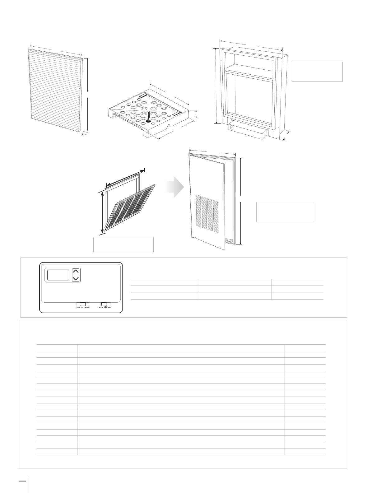
ACCESSORIES
″
29-3/8″
″
1-1/4″
32-5/8
″
23-3/4″
ARCHITECTURAL
LOUVER
RAVAL3
RAVDPLAT
Drain Platform
31-3/4
RETURN AIR GRILLE
RAVRG2
Filter size: 20" x 20" Field supplied
22-1/2"
22-1/2"
23-31/32″
24-35/64″
OR
3-5/8
26-1/2″
Cutout
Dimensions:
24" W x 32" H
″
WALL PLENUM
RAVWPT15
Telescopes
from 8” to 15”
8″- 15″
ACCESS PANEL WITH
RETURN AIR GRILLE
RAVRG4
Filter size: 20" x 24" x 1 or 2”
Field supplied
57-3/8
Cutout
Dimensions:
28-1/8" W x 55-7/8" H
COMPLETE ACCESSORY LIST
KIT NUMBER DESCRIPTION
RAK149F2
RAK149P2
RAK180W1
RAVAL3
RAVRG2
RAVRG4
RAVWPT15
RAVTRANS2
RAVTRANS3
RAVTRANS4
RAK315D
RAK320D
RAK330D
RAK515D
RAK520D
RAK530D
RAVDPLAT
Digital Two-Fan Speed Thermostat
Digital Programmable Thermostat
Energy Management Occupancy Sensing Wired/Wireless Thermostat
Exterior Grille
Return Air Grille for Flush Door
Access Panel with Return Air
Wall Plenum for walls 8” to 15” thick
Transition plenum to adapt existing AZ75/85 wall plenums to AZ95 series
Transition plenum to adapt existing 8” deep (RAVWPT8) AZ9 0/91 plenum to AZ95 series
Transition plenum to adapt existing 14” deep (R AVWPT 14) AZ90/91 plenum to A Z95 series
230/208-Volt Direct Connect Power Supply Kit, 2.45/2 kW heat
230/208-Volt Direct Connect Power Supply Kit, 3.45/2.82 kW heat
230/208-Volt Direct Connect Power Supply Kit, 5/4.08 kW heat
265-Volt Universal Direct Connect Power Supply Kit, 2.45 kW heat
265-Volt Universal Direct Connect Power Supply Kit, 3.45 kW heat
265-Volt Universal Direct Connect Power Supply Kit, 5 kW heat
Drain Platform
Cutout Dimensions:
20-3/8" W x 20-3/8" H
WALL THERMOSTAT
Programmable RAK149P25-wire (AZ95E), 6-wire (AZ95H)
Two speed fan RAK149F26-wire (AZ95E), 7-wire (AZ95H)
Energy Management RAK180W12-wire/wireless
Check the thermostat instructions for correct wiring and installation requirements.
MODEL TYPE KIT NUMBERCOMMUNICATION
FOR ADDITIONAL
INFORMATION
REFER TO PAGES
6
6
6
5
5
5
5
6
6
6
5
5
5
5
5
5
5
Preliminary specifications. Subject to change.
18
Page 19

SPECIFICATIONS
The following are suggested specifications for the AZ95
Series single packaged vertical units:
The contractor shall furnish single packaged vertical units
of the sizes and capacities shown on the schedule or in
the specifications. The units shall be located as shown
on the drawings and each shall consist of a chassis,
appropriately sized wall plenum, outdoor grille, remote
wall thermostat, drain platform, and closet access panel
or door.
Units shall be listed by ETL and shall be GE Appliances
Vertical Zoneline models or equal. Unit dimensions shall
not exceed 23-5/8"W x 24-1/8"L x 31 7/8" H.
CHASSIS
The Zoneline UltimateV10 Vertical chassis shall be
the standard product of the manufacturer and shall
be shipped in protective cartons to prevent damage.
Cartons shall be appropriately marked with factory
wording sufficient to warn handlers against dropping,
improper stacking, upending or rolling.
The chassis shall be slide-in type, ready to operate
after installation.
The chassis shall be protected against the harmful
effects of airborne chemicals and saltwater corrosion.
The chassis shall have a hermetically sealed refrigerant
system with an external vibration isolated rotary
compressor. Indoor coils shall have copper tubing
with aluminum fins. Outdoor coils shall have copper
tubing with aluminum fins treated to resist the effects
of airborne chemicals and salt-water corrosion. All
refrigerant coil fins will have the necessary enhancements
to achieve EER and COP ratings of the unit. Refrigerant
system metering shall be done with capillaries.
Airflow system shall consist of one permanently
lubricated fan motor for the outdoor side and a separate
permanently lubricated two-speed motor for the indoor
blower.
Outdoor fan shall be multi-blade axial-flow design made
of non-corrosive material. Indoor fan shall be blower type
to optimize airflow and minimize air noise. All motors on
the exterior side of the weather barrier shall be painted
and enclosed to reduce the effects of moisture and
corrosion.
Units will have a positive cooling condensate disposal
system. The disposal system shall have a slinger ring on
the outdoor fan to dispose of condensate water and to
assist in cooling the outdoor coil.
Heat pump models shall be equipped with a temperature
activated valve to allow condensate water generated
during defrost cycles to drain into the specified
drain system.
Unit indoor and outdoor airflows must match the
capacity of the coils for efficient heat transfer and meet
latent and sensible heat requirements. Water blow-off
shall not occur on the indoor coil.
Unit shall have a sensor to prevent indoor coil freeze up.
WALL PLENUM
Wall plenums shall be constructed of heavy gauge, zinc
coated, phosphated steel with a baked-on enamel finish.
Plenums shall be installed through the exterior wall where
shown on the plans and shall be of correct depth to allow
sealing to exterior and interior walls.
EXTERIOR GRILLES
Each unit shall be equipped with a standard exterior
grille that has been designed to allow operation in high
ambient conditions.
Special exterior grilles or custom louver sections supplied
by others will conform to minimum free area
requirements and shall be submitted to independent labs,
if requested, for feasibility and air flow characteristics.
ELECTRICAL
Units shall be designed to operate on 230/208
or 265-volts, 60 Hz, single-phase power.
Units shall have means of electrical connection listed by
Underwriters Laboratories and compatible with the units'
required voltage and ampacity in conformance with
National Electrical Code (NEC) and all local codes.
FEATU RES
Unit must be compatible with 2-wire Central Desk
Control systems.
Units must be compatible with Electronic Class-2 remote
wall thermostats.
Unit shall be equipped with Freeze Sentinel to
automatically activate the electric heaters (at 41°F)
and appropriate fan motors to warm and circulate
indoor air (to 46°F) to prevent damage due to freezing
temperatures. Freeze Sentinel shall operate when unit is
connected to a powered electrical circuit.
Unit shall be equipped with Heat Sentinel to
automatically provide cooling at 85o F to prevent an
excessively hot room. Once the room temperature
reaches 80o F, the air conditioner will turn off. When
activated, Heat Sentinel shall operate when unit is
connected to a power electrical circuit.
Preliminary specifications. Subject to change.
19
Page 20
GE APPLIANCES VERTICAL ZONELINE HEAT PUMPS ADDITIONAL
SPECIFICATIONS
Heat pump unit shall automatically switch from heat
pump operation to electric resistance heat when it
is unable to provide sufficient heat to maintain room
temperature or when the outdoor temperature is
25o F or less.
In the event of a compressor failure during heat pump
operation, the unit shall automatically switch to electric
resistance heat to maintain selected room temperature
regardless of outdoor temperatures.
Unit shall have an indoor coil temperature sensor to
protect the compressor when the outdoor temperatures
are too high for heat pump operation.
ADDITIONAL SPECIFICATIONS SERVICE
Submit complete information with bid covering service
availability, to whom service on units will be assigned,
complete address and phone number, including phone
number of emergency service personnel.
STARTUP, ADJUST, DEMONSTRATE
Contractor shall be responsible for the initial starting
of units, adjustments thereto, cleaning, etc., to place the
units in required operating condition. Contractor shall
demonstrate to the owner, or his representative, the
operation of units for both summer and winter functions.
ZONELINE SINGLE PACKAGED VERTICAL UNIT NOMENCLATURE
The Vertical Zoneline chassis is identified by a model number defining the type of unit, cooling capacity, electrical
information and optional features included on the unit. When specifying or ordering the Zoneline chassis, use of this
nomenclature will ensure receiving the correct unit.
AZ95H12DAC
Zoneline
Chassis series
95=heat pump single
packaged vertical unit
Unit type
H= heat pump with electric
resistance heat
E=cooling with electric
resistance heat
Nominal cooling capacity
09=9,000 BTUh cooling
12=12,000 BTUh cooling
18=18,000 BTUh cooling
Voltage/Phase/Frequency
D= 230/208 Volt, single
phase, 60 Hz
E= 265 Volt, single phase,
60 Hz
Universal power
connection
Special features
C=Corrosion treated
Preliminary specifications are subject to change
20
Page 21

ZONELINE WARRANTY
Proof of original purchase date is needed to obtain
service under warranty. For service in the U.S., call
1-844-GE4-PTAC (1-844-434-7822). In Canada,
contact your local distributor.
WHAT IS COVERED
LIMITED ONE-YEAR WARRANTY
For one year from date of original purchase, we will
provide, free of charge, parts and service labor on site
to repair or replace any part of the Zoneline unit that
fails because of a manufacturing defect.
LIMITED ADDITIONAL FOUR-YEAR SEALED
REFRIGERATING SYSTEM WARRANTY
For four years from the date of original purchase, we
will provide, free of charge, parts and on site service
labor to repair or replace any part of the sealed
refrigerating system (the compressor, condenser,
evaporator and all connecting tubing) that fails
because of a manufacturing defect.
LIMITED 2ND THROUGH 5TH YEAR PARTS
WARRANTY
For the second through the fifth year from date
of original purchase, GE Appliances will provide, free
of charge, parts that fail as a result of a manufacturing
defect. Parts covered are fan motors, switches, heater,
heater protectors, compressor overload, solenoids, circuit
boards, auxiliary controls, thermistors, frost controls,
capacitors, varistors and indoor blower bearing. This is
a limited parts-only warranty, and does not include labor
or transportation to and from the service shop.
WHAT IS NOT COVERED
• Service trips to your site to teach you how to use
the product.
• Improper installation.
If you have an installation problem, or if the air
conditioner is of improper cooling capacity for the
intended use, contact your dealer or installer. You
are responsible for providing adequate electrical
connecting facilities.
• Replacement of fuses or resetting of circuit breakers.
• In commercial locations, labor necessary to move the
unit to a location where it is accessible for service by
an individual technician.
• Failure of the product resulting from modifications to
the product or due to unreasonable use including failure
to provide reasonable and necessary maintenance.
• Failure or damage resulting from corrosion due to
installation in an environment containing corrosive
chemicals.
• Failure or damage resulting from corrosion due to
installation in a coastal environment, except for models
treated with special factory-applied anti-corrosion
protection as designated in the model number.
• Damage to product caused by improper power supply
voltage, accident, fire, floods or acts of God.
• Incidental or consequential damage to personal
property caused by possible defects with this air
conditioner.
WARRANTOR: GE APPLIANCES.
LOUISVILLE, KY 40225
This warranty is extended to the original purchaser and
any succeeding owner for products purchased for use
within the USA and Canada. In Alaska, the warranty
excludes the cost of shipping or service calls to your site.
Some states do not allow the exclusion or limitation of
incidental or consequential damages. This warranty gives
you specific legal rights, and you may also have other
rights which vary from state to state. To know what your
legal rights are in your state, consult your local or state
consumer affairs office or your state’s Attorney General.
Equipment used as a primary source for heating or cooling is an integral part of the building in which it is installed. Proper application is
essential for satisfactory performance over a wide range of operating conditions. It is strongly recommended that a professional engineer
determine proper application. If this unit is a replacement unit, its specifications and performance may differ from those of the unit it is
replacing. For that reason, we again strongly recommend that a professional engineer determine proper application.
GE Appliances has a policy of continuous improvement on its products and reserves the right to change materials and specifications
without notice.
Preliminary specifications are subject to change
21
Page 22

Preliminary specifications. Subject to change.
22
Page 23

Preliminary specifications. Subject to change.
23
Page 24

GE is a trademark of the General Electric Company.
Manufactured under trademark license.
Copyright ©2020 GE Appliances. All rights reserved.
Zoneline, UltimateV10 and other names are trademarks
or registered trademarks of GE Appliances in the United
States and other countries.
Appliance Park
Louisville, KY 40225
geappliances.com
zoneline.com I 888.231.2548
OTGEA20621
 Loading...