

GE AZ85W18DACM2, AZ85H18EACM2, AZ85H18DACM3, AZ85H18DACM2, AZ85E18EACM2 Owner’s Manual
...
GEAppliances.com
Safety Instructions ........... 2
O1
@
®I
N
U
0
0_
Operating Instructions
Controls--Dip Switches ......... 3-5
Controls--Terminal
Connections ................... 6, 7
On/Off Switch .................... 8
Ventilation Control ............... 8
Care and Cleaning
Air Filters ........................ 9
Base Pan ........................ 9
Exhaust Coils..................... 9
Installation Instructions
Preparation ..................... 10
Electrical Supply .............. 11-13
Installing the Zoneline ........ 14-21
Servicing ........................ 22
Troubleshooting Tips ....... 25
Normal Operating Sounds....... 24
Consumer Support
Consumer Support ...... Back Cover
Warranty ....................... 27
Cool Only, Heat/Cool and
Heat Pump Hodels
8500 Series
Write the model and serial numbers
here:
Model #
!
Serial #
You can find them on a label on the front
case panel.
Printed in China TINSEA612JBRZ 49-7639-1 03-12 GE
IMPORTANT SAFETY INFORMATION.
READ ALL INSTRUCTIONS BEFORE USING.
A WARNING!
Riskof electric shock. Can cause injury or death. For your safety, the information in this manual
must be followed to minimize the risk of fire, electric shock or personal injury.
SAFETYPRECAUTIONS
[]
This Zoneline must be properly installed
in accordance with the Installation
Instructions before it is used.
See the Installation Instructions
in the back of this manual.
[]
Replace immediately all electric service
cords that have become frayed or
otherwise damaged. A damaged power
supply cord must be replaced with
a new power supply cord obtained
from the manufacturer and not repaired.
Do not use a cord that shows cracks
or abrasion damage along its length
or at either the plug or connector end.
[]
Product must be operated with
the electrical plug supplied with the
product. Do not replace the electrical
plug supplied with the product.
[]
If the receptacle does not match the plug,
the receptacle must be changed out by
a qualified electrician.
[] Unplug or disconnect the Zoneline
at the fuse box or circuit breaker before
making any repairs.
NOTE: We strongly recommend that
any servicing be performed by a qualified
individual.
[] All air conditioners contain refrigerants,
which under federal law must be
removed prior to product disposal.
If you are getting rid of an old product
with refrigerants, check with the
company handling disposal about
what to do.
[]These R410A Air Conditioner Systems
require contractors and technicians to
use tools, equipment and safety standards
approved for use with this refrigerant.
DO NOT use equipment certified for R22
refrigerant only.
READAND FOLLOW THISSAFETYINFORMATION CAREFULLY.
SAVE THESE INSTRUCTIONS
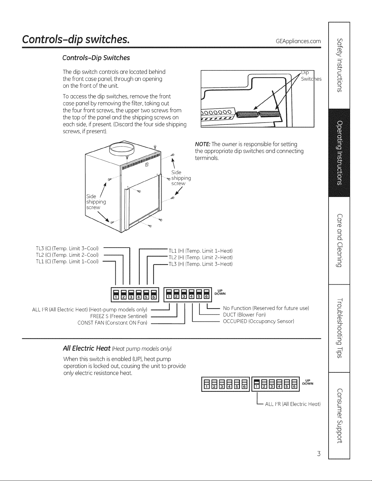
Controls-dip switches. GEAppliances.com
Controls-Dip Switches
Thedip switch controls are located behind
the front case panel,through an opening
on the front of the unit.
Toaccessthe dip switches, remove the front
case panel by removing the filter, taking out
the four front screws, the upper two screws from
the top of the panel and the shipping screws on
each side, if present. (Discard the four side shipping
screws,if present).
NOTE:Theowner is responsiblefor setting
the appropriate dip switches and connecting
terminals.
Side
---._shipping
screw
,/
TL3 (C)(Temp. Limit 3-Cool)
TL2 (C)(Temp. Limit 2-Cool)
TL! (C)(Temp. Limit !-Cool)
ALL 12R(All Electric Heat)(Heat-pump models only)
FREEZ S (Freeze Sentinel)
CONST FAN (Constant ON Fan)
All Electric Heut (Heat pump models only)
When this switch isenabled (UP),heat pump
operation is locked out, causing the unit to provide
only electric resistance heat.
fL! (H)(Temp. Limit !-Heat)
_TL2 (H)(Temp. Limit 2-Heat)
_TL3 (H)(Temp. Limit 3-Heat)
OCCUPIED(OccupancySensor)
(BBBBBBiImBBBBBIooO °
hALL FR(AllElectricHeat)
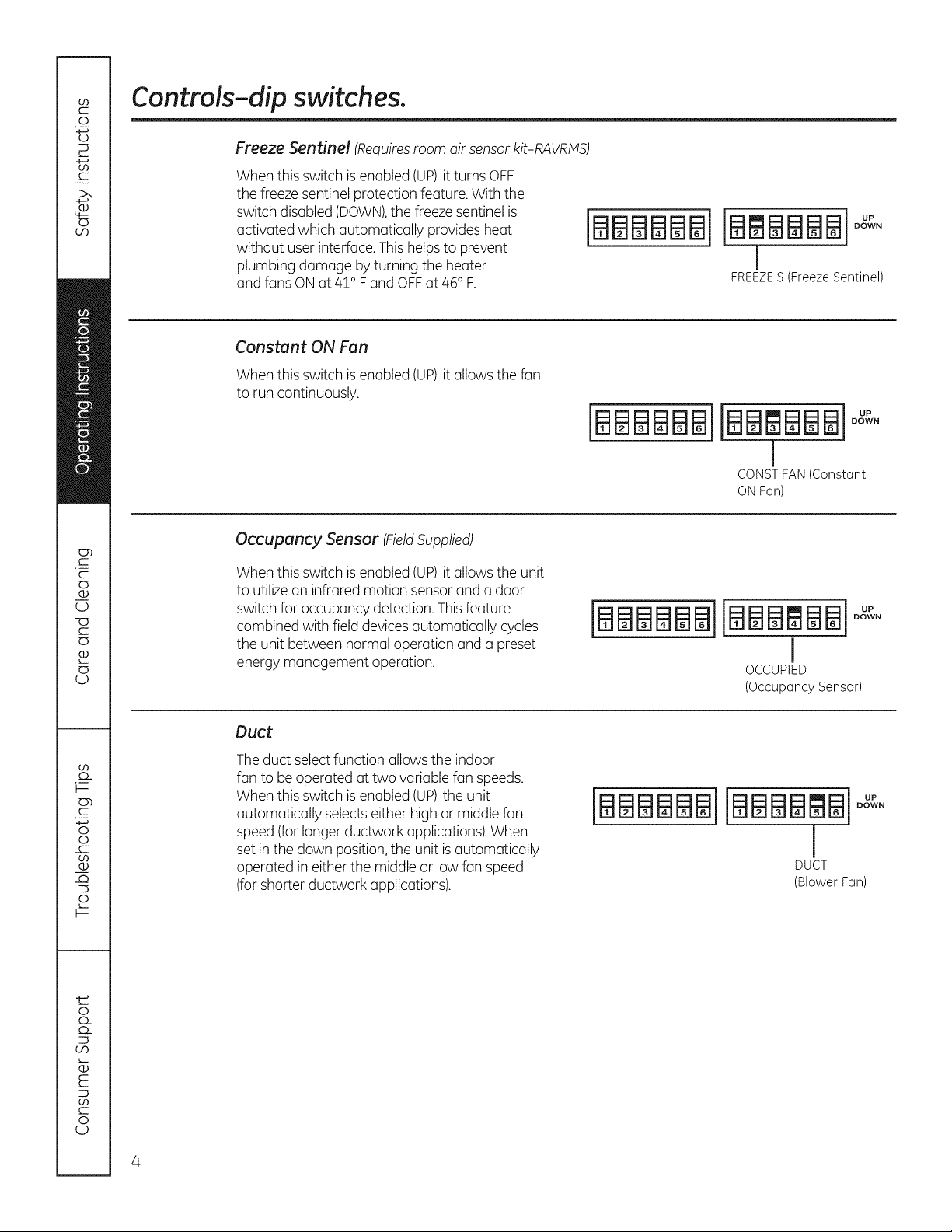
Controls-dip switches.
Freeze Sentinel (Requiresroom air sensor kit-RAVRPtS)
When this switch isenabled (UP),itturns OFF
the freeze sentinel protection feature. With the
switch disabled (DOWN),the freeze sentinel is
activated which automatically provides heat
without userinterface. Thishelpsto prevent
plumbing damage by turning the heater
and fans ON at 4! ° F and OFF at 46° F.
Constant ON Fan
When this switch isenabled (UP),it allowsthe fan
to run continuously.
Occupancy Sensor (FieldSupplied)
[BBBBBBI
IBBBBBBI°°L_°
I
FREEZES (Freeze Sentinel)
IBBBBBBIIBB BBBI
J
CONST FAN (Constant
ONFan)
When this switch isenabled (UP),it allowsthe unit
to utilize an infrared motion sensor and a door
switch for occupancy detection. Thisfeature
combined with field devicesautomatically cycles
the unit between normal operation and a preset
energy management operation.
Duct
Theduct select function allows the indoor
fan to be operated at two variable fan speeds.
When this switch isenabled (UP),the unit
automatically selectseither high or middle fan
speed (forlonger ductwork applications).When
set in the down position,the unit isautomatically
operated in either the middle or low fan speed
(forshorter ductwork applications).
iBBBBBBiiBBBmBBI
I
OCCUPIED
(OccupancySensor)
iBBBBBBiiBBBBBBioo_o
J
DUCT
(BlowerFan)
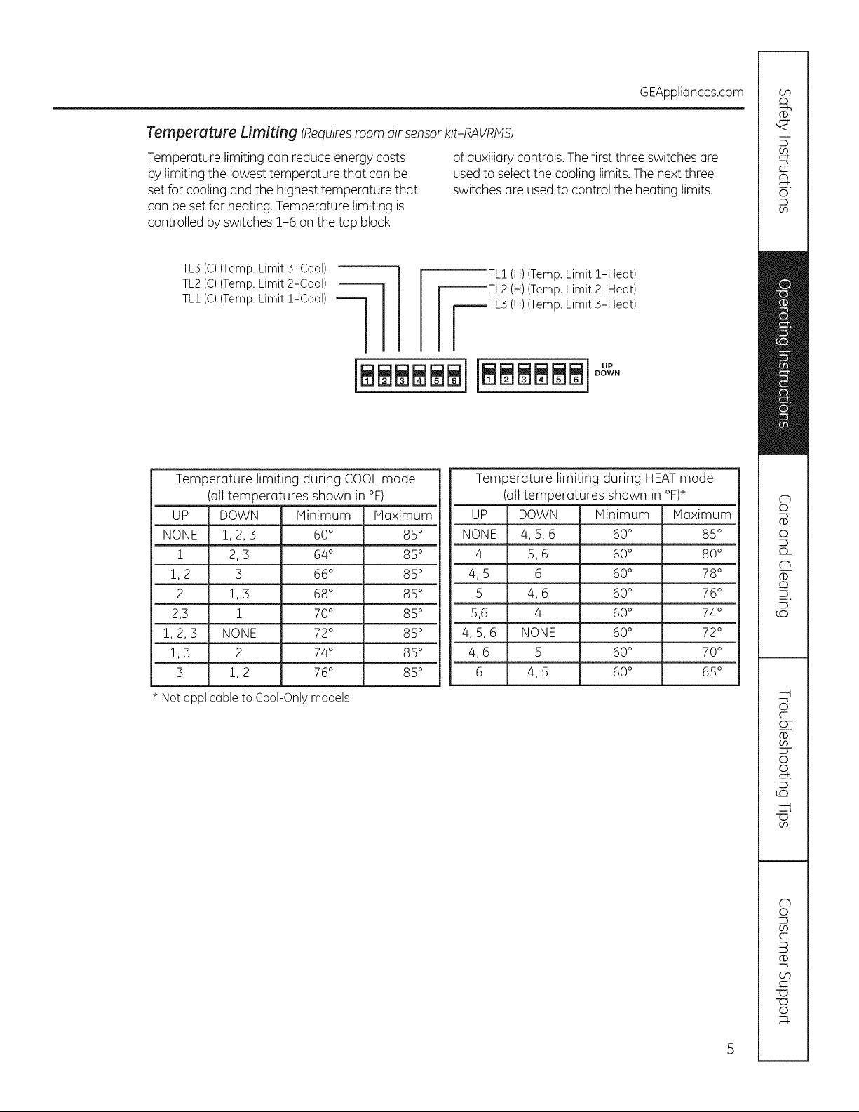
Temperature Limiting (Requiresroom air sensorkit-RAVRMS)
Temperature limiting can reduce energy costs
by limiting the lowest temperature that can be
set for cooling and the highest temperature that
of auxiliary controls, Thefirst three switches are
usedto select the cooling limits.Thenext three
switches are used to control the heating limits.
can be set for heating. Temperature limiting is
controlled by switches 1-6 on the top block
GEAppliances.com
TL3(C)(Temp. Limit S-Cool)
TL2(C)(Temp. Limit 2-Cool)
TL! (C)(Temp. Limit Z-Cool)
Temperature limiting during COOL mode
(all temperatures shown in °F)
UP DOWN Minimum Maximum
NONE !, 2, 3 60 ° 85 °
! 2, 3 64° 85°
1, 2 3 66 ° 85 °
2 !, 3 68 ° 85 °
2,3 ! 70 ° 85 °
1, 2, 3 NONE 72° 85 °
!, 3 2 74 ° 85 °
3 1, 2 76° 85 °
[L! (H)(Temp. Limit !-Heat)
_TL2 (H)(Temp. Limit 2-Heot)
_TL3 (H)(Temp. Limit 3-Heot)
Temperature limiting during HEAT mode
(all temperatures shown in °F)*
UP DOWN Minimum Maximum
NONE 4, 5, 6 60° 85 °
4 5, 6 60° 80 °
4, 5 6 60° 78 °
5 4, 6 60° 76 °
5,6 4 60 ° 74 °
4, 5, 6 NONE 60° 72 °
4, 6 5 60° 70 °
6 4, 5 60° 65 °
* Not opplicable to Cool-Only models
5
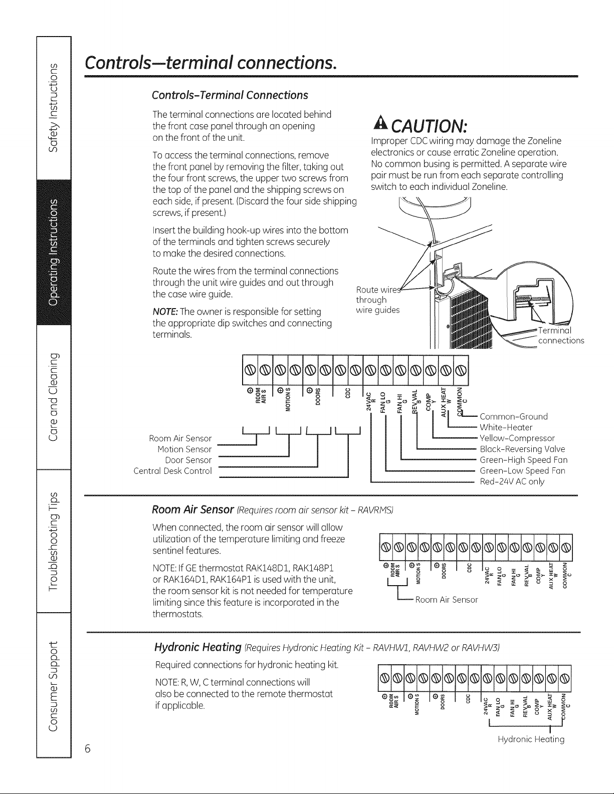
Controls-terminal connections.
Controls-Terminal Connections
Theterminal connections are located behind
the front case panel through an opening
on the front of the unit.
Toaccessthe terminal connections, remove
the front panel by removing the filter, taking out
the four front screws, the upper two screws from
the top of the panel and the shipping screws on
each side,if present.(Discardthe four sideshipping
screws,if present.)
Insertthe building hook-up wires into the bottom
of the terminals and tighten screws securely
to make the desired connections.
Routethe wires from the terminal connections
through the unit wire guides and out through
the case wire guide.
NOTE:Theowner isresponsible for setting
the appropriate dip switches and connecting
terminals.
A CAUTION:
Improper CDCwiring may damage the Zoneline
electronics or cause erratic Zoneline operation.
Nocommon busing ispermitted. Aseparate wire
pair must be run from each separate controlling
switch to each individual Zoneline.
through
wire guides
connections
e-_l n le_ I _ Io s _ _ _ _ _
_:< g o X'_zo zo >+, ,_+'
_ "< "< _ _Common-Ground
Room Air Sensor
Motion Sensor
Door Sensor
Central Desk Control
Room Air Sensor (Requiresroom air sensorkit - RAVRMS)
When connected, the room air sensor will allow
utilization of the temperature limiting and freeze
sentinel features.
NOTE:If GEthermostat RAK148D1,RAK148P1
or RAK164D1,RAK164P1is used with the unit,
the room sensor kit isnot needed for temperature
limiting since this feature isincorporated in the
thermostats.
Hydronic Heating (RequiresHydronicHeating Kit - RAVHWff,RAVHW2or RAVHW3)
Requiredconnections for hydronic heating kit.
NOTE:R,W,Cterminal connections will
alsobe connected to the remote thermostat
ifapplicable.
ommIo+ I++ I _ Io =+ _ +
L_+ _ "< "< #: u _ 8
RoomAir Sensor
O+:le+ e+ + _ o, + >_+ + o_
+_ + o +ii,=+.+°++°_+_+._+=++
White-Heater
Yellow-Compressor
Black-Reversing Valve
Green-High Speed Fan
Green-Low Speed Fan
Red-24V AC only
L '! r
HydronicHeating
t
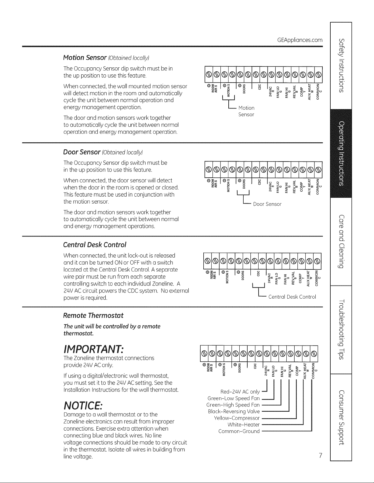
Notion Sensor (Obtainedlocally)
TheOccupancy Sensor dip switch must be in
the up position to usethis feature.
When connected, the wall mounted motion sensor
will detect motion in the room and automatically
cyclethe unit between normal operation and
energy management operation.
Thedoor and motion sensors work together
to automatically cyclethe unit between normal
operation and energy management operation.
Door Sensor (Obtainedlocally)
TheOccupancy Sensor dip switch must be
in the up position to use this feature.
When connected, the door sensorwill detect
when the door in the room is opened or closed.
Thisfeature must beused in conjunction with
the motion sensor.
Thedoor and motion sensors work together
to automatically cyclethe unit between normal
and energy management operations.
GEAppliances.com
L_ _ ,,< ,,<_ o _ o
Notion
Sensor
e+;le m le o I _ I_ s _ _ _ _ +
+"°9_ oorfol+°
Central Desk Control
When connected, the unit lock-out is released
and it can be turned ONor OFFwith a switch
located at the Central DeskControl.A separate
wire pair must be run from each separate
controlling switch to each individual Zoneline. A
24VACcircuit powers the CDCsystem. Noexternal
power isrequired.
Remote Thermostat
Theunit will be controlled by u remote
thermostat.
IMPORTANT:
TheZoneline thermostat connections
provide 24V AConly.
If using a digital/electronic wall thermostat,
you must set it to the 24VACsetting. Seethe
Installation Instructions for the wall thermostat.
NOTICE:
Damage to a wall thermostat or to the
Zonelineelectronics can result from improper
connections. Exerciseextra attention when
connecting blue and black wires. No line
voltage connections should be made to any circuit
in the thermostat. Isolate all wires in building from
line voltage.
B®®d+®®®®®®®®®®
e_;Io+ le ° I _ I_ s _ d _ _ o_
"" _ g L_ _e::r aii::k _ itlol °
emile+ Io_ I _ Io _ _ +
= _ ,,< ,,< ore°_ o
I I
Red-24VAConlyJ I
Green-LowSpeedFan
Green-HighSpeedFan
Black-ReversingValve
Yellow-Compressor
White-Heater
Common-Ground
__J
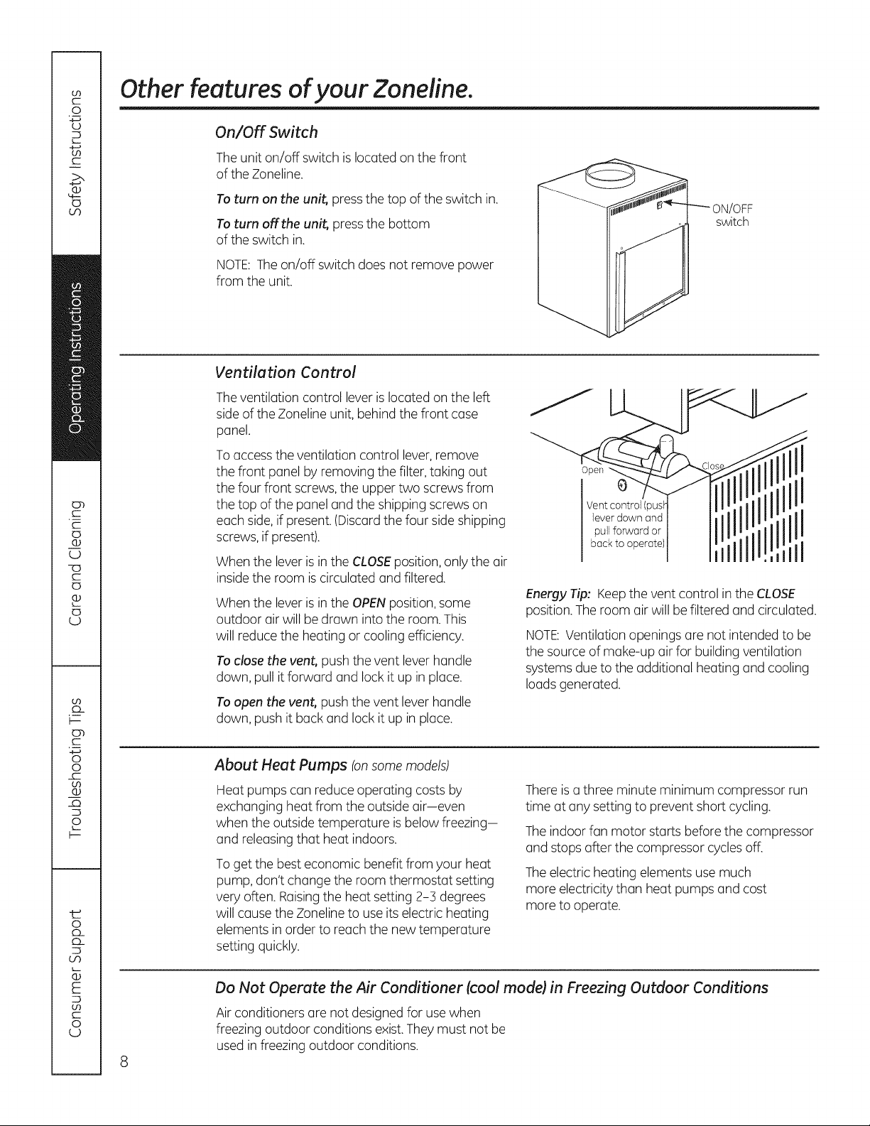
Other features ofyour Zoneline.
On/Off Switch
Theunit on/off switch islocated on the front
of the Zoneline.
Toturn on the unit, pressthe top of the switch in.
Toturn off the unit, pressthe bottom
of the switch in.
NOTE:The on/off switch does not remove power
from the unit.
Ventiletion Control
Theventilation control lever is located on the left
sideof the Zoneline unit, behind the front case
panel.
Toaccessthe ventilation control lever,remove
the front panel by removing the filter, taking out
the four front screws, the upper two screws from
the top of the panel and the shipping screws on
each side,if present.(Discardthe four side shipping
screws,if present).
When the leverisin the CLOSEposition,only the air
insidethe room iscirculated and filtered.
When the leverisin the OPENposition,some
outdoor air will be drawn into the room. This
will reduce the heating or cooling efficiency.
Toclose the vent, push the vent lever handle
down, pull it forward and lock it up in place.
Toopen the vent, push the vent lever handle
down, push it back and lock it up in place.
ON/OFF
switch
Open
g
Vent control (push
lever down and
pull forward or
back to operate)
Energy Tip: Keepthe vent control in the CLOSE
position.The room air will be filtered and circulated.
NOTE:Ventilation openings are not intended to be
the source of make-up air for buildingventilation
systems due to the additional heating and cooling
loadsgenerated.
I
I
I
About Heet Pumps (onsome models)
Heat pumps can reduce operating costs by
exchanging heat from the outside air-even
when the outside temperature is below freezing-
and releasing that heat indoors.
Toget the best economic benefit from your heat
pump, don't change the room thermostat setting
very often. Raisingthe heat setting 2-3 degrees
will cause the Zoneline to use its electric heating
elements in order to reachthe new temperature
setting quickly.
Do Not Operate the Air Conditioner (cool mode) in Freezing Outdoor Conditions
Air conditioners are not designed for usewhen
freezing outdoor conditions exist.Theymust not be
used in freezing outdoor conditions.
There isa three minute minimum compressor run
time at any setting to prevent short cycling.
The indoor fan motor starts before the compressor
and stops after the compressor cyclesoff.
Theelectric heating elements use much
more electricity than heat pumps and cost
more to operate.
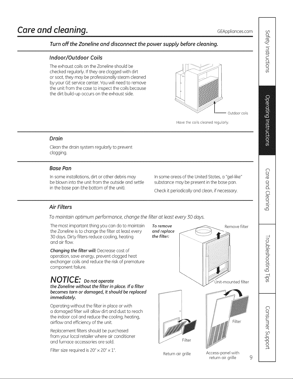
Care and cleaning. GEAppliances.com
Turn off the Zoneline and disconnect the power supply before cleaning.
Indoor/Outdoor Coils
Theexhaust coils on the Zonelineshould be
checked regularly. If they are clogged with dirt
or soot, they may be professionally steam cleaned
byyour GEservicecenter.Youwill need to remove
the unit from the case to inspectthe coils because
the dirt build-up occurs on the exhaust side.
-- Outdoor coils
Have the coils cleaned regularly.
Drain
Cleanthe drain system regularly to prevent
clogging.
Base Pan
In some installations, dirt or other debris may
be blown into the unit from the outside and settle
in the base pan (the bottom of the unit).
Air Filters
To maintain optimum performance, change the filter at least every 50 days.
Themost important thing you can do to maintain
the Zonelineisto change the filter at least every
30 days. Dirty filters reduce cooling, heating
and air flow.
Changing the filter will'.Decreasecost of
operation, saveenergy, prevent clogged heat
exchanger coils and reduce the risk of premature
component failure.
Insome areas of the United States,a "gel-like"
substance may be present in the base pan.
Checkit periodically and clean, if necessary.
Toremove
and replace
the filter:
NOTICE: Do notoperate
the Zoneline without the filter in place. Ifa filter
becomes torn or damaged, it should be replaced
immediately.
Operating without the filter inplace or with
a damaged filter will allow dirt and dust to reach
the indoor coil and reduce the cooling, heating,
airflow and efficiency of the unit.
Remove filter
filter
Filter
Replacement filters should be purchased
from your local retailer where air conditioner
and furnace accessoriesare sold.
Filtersize required is20" x 20" x 1".
Filter
Return air grille Access-panel with
return air grille 9
 Loading...