

GE AZ75W18DACM1, AZ75W12DACM1, AZ75W09DACM1 Owner’s Manual
o_
Safety Instructions ........... 2
Operating It_truc¢ions
Controls--Dip Swit( hes ...... 3-5
Comrols--T_ rminaI
Comle( tions .............. 6, 7
On/Off Swit( h ............... 8
\\ milation Control ........... 8
Care and Cleaning
Air Fihers ................... 9
Base Pan ................... 9
Exhaust Coils ................ 9
Installation Instructions
Ele(trk al Supply ......... 11-13
Installing the Zoneline .... |4-91
Preparation ................ 10
Servicing .................. 22
ge.com
Heal/Cool and
Heal Pum/_ Models
7500 Series
Troubleshooting _l_ps ....... 93
Normal ()p_ rating Sounds .... 24
Consumer Support
Consum(r Support . . .Back Cover
Product R(gistration ...... 25, 26
Wa rra_l _v .................. 27
Write the model and serial
numbers here:
Model #
Serial #
Find these numbers on a label
on the flont case pmlel.
TINSEA469JBRZ 49-7561 10-06JR
IMPORTANTSAFETYINFORMATION.
READALLINSTRUCTIONSBEFOREUSING.
WARNING!
Foryour safe_ the information in this manual must be followed to minimize the risk of fire, electric
shock, or to prevent property damage, personal injury, or loss of life.
_l I S
..,.__ SAFETYPRECAUTIONS
_,/_ • This Zoneline m s be prop _ ?
installed in a<<ordan(e with the
Installation [nsUuctions betbt-_ it is
used. See the Installation Instructions
in the back of this manual.
R_ place imm(diat(ly all (lectric service
cords thal have becom( IF,fled or
odmrwise damag< d. A damag(d pow(r
supply (ord must be replaced with a
new pow<r supply coi*t obtained from
the manuf_ictm'er and not repaired.
Do no{ use a cord dmt shows ctvlcks or
abrasion damage along its length or at
(ith( r _1_ plug or col'me(tot (rid.
• Unplug or discmme(t tile Zoneline at
the fi_se box or circuit break( r betore
making any repairs.
NOTE: W_ strongly recommend dmt any
s<rvi_ ing be p_ rfbrm_ d l>y a qualified
individual.
• All air conditioners contain refl'igerants,
which trader fi_,deral law must be
removed prior to product disposal. If
you are ge{ting rid of an old produ({
with refi-igerants, che(k with the
company handling disposal about what
to do.
_Qf'_'.; READANDFOLLOWTHISSAFETYINFORMATIONCAREFULLY.
I _U'\_ SAVETHESEINSTRUCTIONS
2
Controls-dipswitches. o.oom
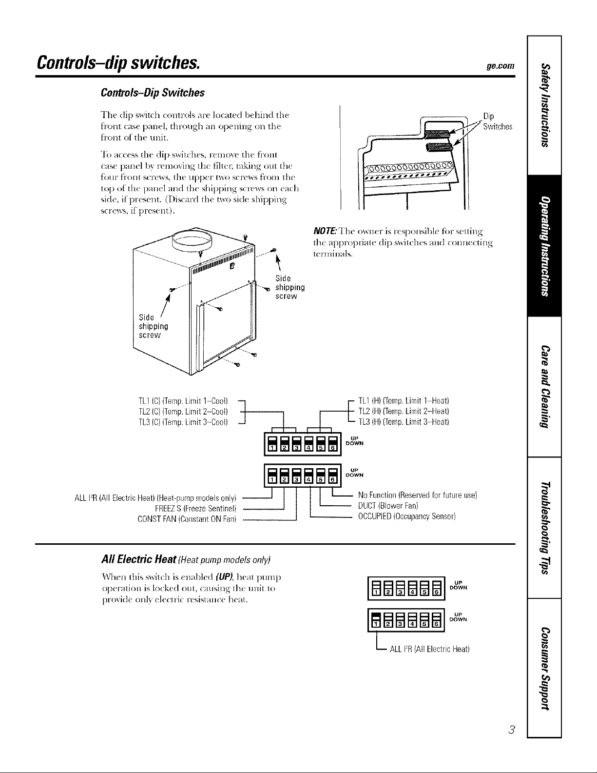
Controls-DipSwitches
Tim di 1)_wixch cc,nlrols are localed l:,ehind th_
fronl case panel, through an opening on lh(
front of the trait.
"1\__mcess tile dip switch(s, rcmovc tile fl-ont
case panel by r_moving tile fihe_; raking out tile
tk_ur h-ont screws the upper two screws from the
top ot th( panel und the shipping screws on euda
side, il present. (Disc_wd the two sid( shipping
screws, if present).
NOT£"The owzler is responsil)le f_)l-settin
the appropriate dip switches and connecxing
terminals.
Side
shipping
screw
TL1(C)(Temp.Limit1-Cool)
TL2(C)(Temp.Limit2-Cool)
TL3(C)(Temp.Limit3-Cool)
ALLFR(All ElectricHeat)(Heat_pumpmodelsonly) --
FREEZS(FreezeSentinel)
CONSTFAN(ConstantONFan)
_1 ,--L-_ ,-.b. _- •
All Electric Heat (Heatpumpmodels onl V)
Wh(n this switch is (nabl(d (UP), h(at pump
op(ration is lo(k(d out, (ausing the unit 1o
proxid( only ekctri( resismn(( h(at.
F TL1(H)(Temp.Limit1-Heat)
I I I I I I
$$$$$$ 0.
DOWN
TL2(H)(Temp.Limit2-Heat)
TL3(H)(TempLimit3-Heat)
BSma$$ °°
LBBBBB
ALL12R(All ElectricHeat)
DOWN
3
Controls-dipswitches.
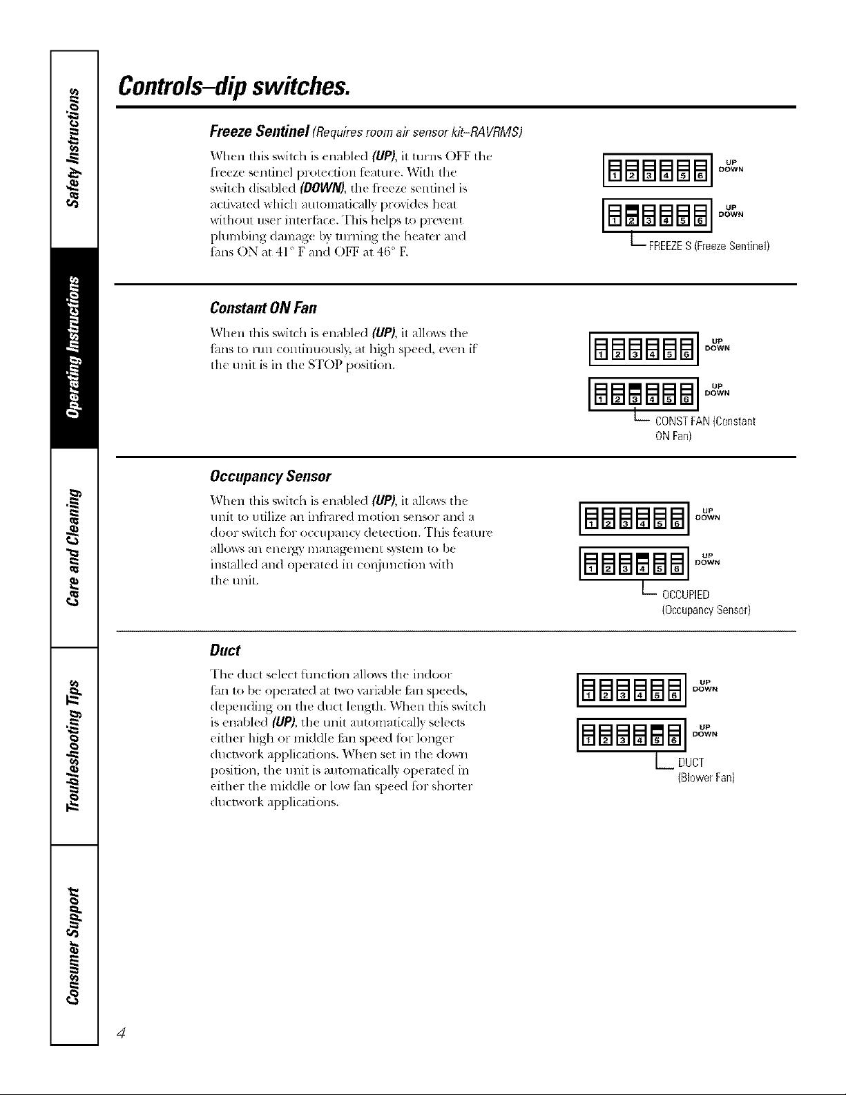
Freeze Sentinel (Requiresroomair sensorkit-RAVRMS)
When this _wilda is enabled (UP), it ulrns OFF the
fl-eeze sentinel protection tbature. With the
switch disabled (DOWN), the fl-eeze sentinel is
actiu/ted which automatically provides heat
without us(r intertbce. This helps to [)revent
pluml)ing damag_ by turning the hearer and
thns ON at 41 ° F and O1_ at 46' E
ConstantONFan
When this switd_ is un_d_h'd (UP), it a]low_ tll_'
_hns to lun continuously, at high speed, even if
tile unit is ill tile STOP position.
Occupancy Sensor
When this _witdl is enabled (liP), it allo_s the
unit to utilize an infl-ared motion sensor and a
door ,;witch fbr o( cupanQ" detection. This fi,aturc
allows an enel_" management _,yamm to be
installed and operated in COiljunction with
the trait.
IBEaBBBBI
[#lmBm8l ]°"
L FREEZES(FreezeSentinel)
[mmmmm °"
BSglSB8
L_ CONSTFAN(Constant
ONFan}
DOWN
DOWN
DOWN
DOWN
[B88#188]OXeN
B88glS8
L OCCUPIED
DOWN
(OccupancySensor}
Duct
The <luct select fimction allows th< indoor
_hn to be operamd at lWO v_lriabl_ tm speeds,
d{ pending on the ducl length. When this switch
is enabled (UP), the unit mltomalically selects
either high or middle tm speed fi_r longer
ducp, vork applications. When set ill llle down
position, th_ u nit is mltomatically operated in
either th_ mkldle or low tim sp_ed lot short_ r
dtlclwork applications.
4
BBBBBB °"
DOWN
DOWN
L DUCT
(BlowerFan)
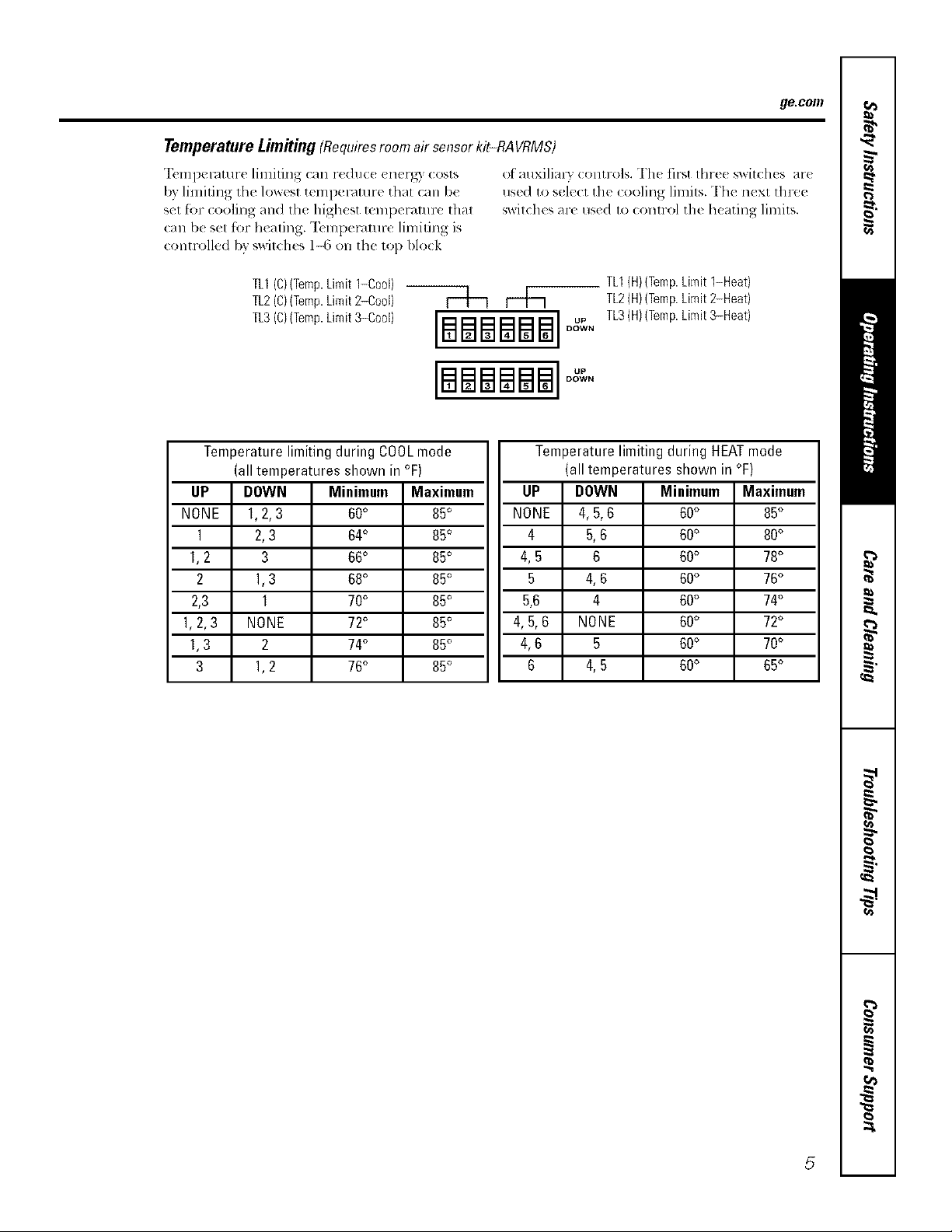
TemperatureLimitiug(Requiresroom airsensor kit-RAVRMS)
"12,mperamre limiting can reduc((nerg) costs
by limiting tile lowest temperature that can be
set for cooling and the highest mml)eramre that
call b( set for heating. "Ik'mperamre limiting is
controlled bv v_vitches 1-6 on the top block
of auxilialw contr,,4s. The fit-,tthre( switches are
use(1 to sol(c1 tilt (ooling lilnits. Th( n(xt tln-ee
sx_itches are used to (ontrol the heating limits.
ge.com
TL1(C)(Temp.Limit1-0oo0
TL2(C)(Temp.Limit2-Cool) |
TL3(C,(Temp.Limit3-Coo0 [[_]_] u.
Temperature limiting during COOLmode
I
NONE
1.2,3
(all temperatures shown in °F)
UP
1,2
2,3
1,3
DOWN
1,2,3
1
2
3
2,3
3
1,3
1
NONE
2
1,2
Minimum Maximum
60° 85°
64° 85°
66° 85°
68° 85°
70° 85°
72° 85°
74° 85°
76° 85°
DOWN
[BSBSBS]°°
I
NONE
4.5.6
DO_v'VN
Temperature limiting during HEATmode
(all temperatures shown in °F)
UP
4
4,5
5
5.6
4,6
6
DOWN
4,5.6
5.6
4,6
NONE
4.5
TL1(H}(Temp.Limit 1-Heat)
TL2(H)(Temp.Limit2-Heat)
TL3(H)(Temp.Limit3-Heat)
Minimmn
60°
60°
6
4
5
60°
60°
60°
60°
60°
60°
Maximum
85°
80°
78°
76°
74°
72°
70°
65°
5
Controls--terminal connections.
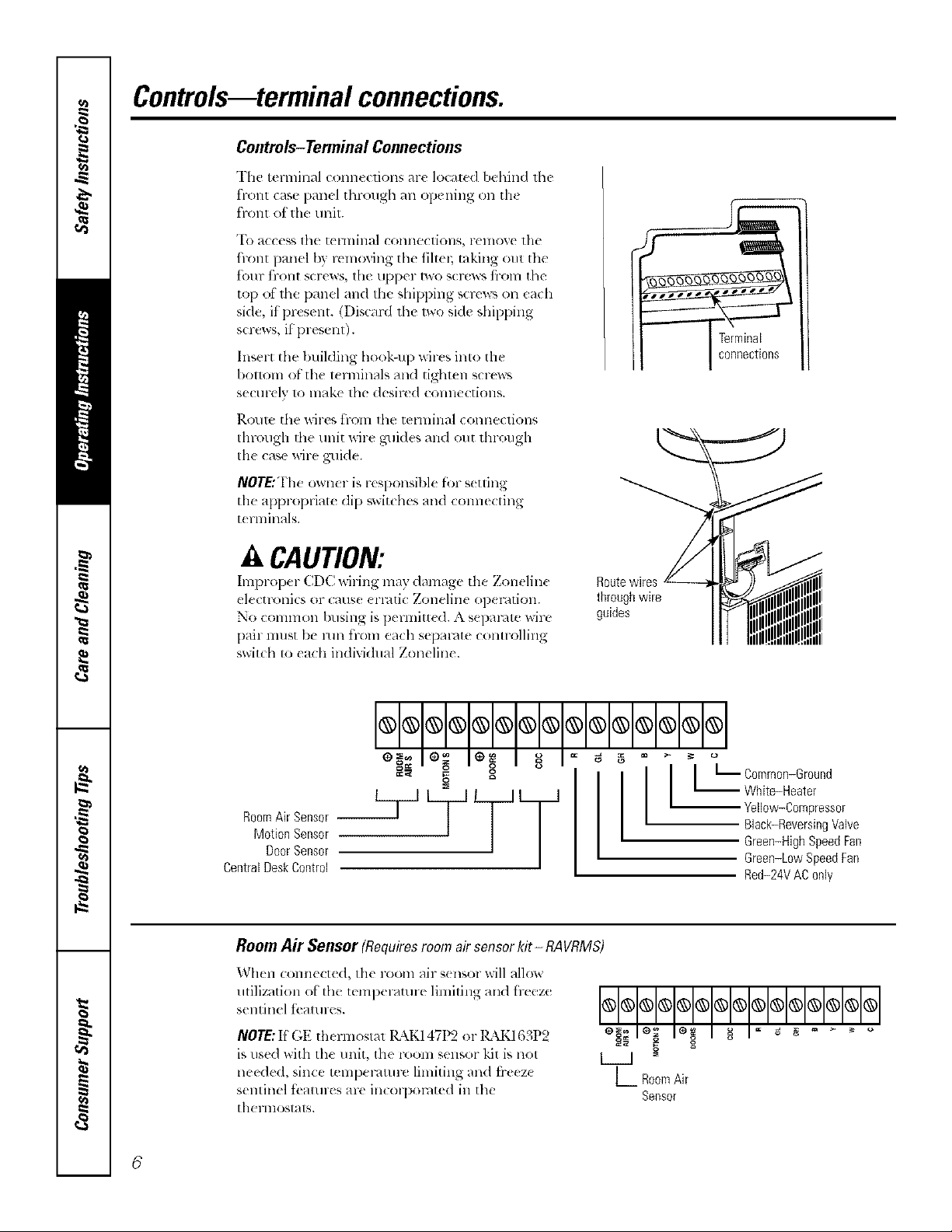
Controls-Terminal Connections
The terminal conn,(lions ar( locate<l behind lh{
t"1-O111 (2_tS{_ }}{/ll_._l [hl'oll_h _111 op( llillg (Ill 111(
front of the unit.
"I() access lhe tel lnillal COlllleCtiOllS, l-ellvY, e tlle
hont panel by removing tile tiltm; taking out tile
t()lll" tl'llll[ screws, tile tipper two screws t}-oln tile
top of the panel and tile shipping scrcw_ on each
side, if present. (Discard th{ lwo side shipping
screws, if present).
Insert the building he,ok-up wilxs inlo the
I)ollo111 o[ tile 1_ rnlinals and tighl_ n s_rews
sectll-t Iv 1o lnake lhe desired COllllecti(_llS.
l_.Ol/le the wil-es tFOlll lll(f tel'lnille.l ( Olllle(liOllS
Ihrough d_e unit Mre guides and out through
Ill{ case wire guide.
NOTE:The owner is r{ Sl)Onsibl( fbr s{ uing
the appropriat( dip swit(hes and coral{ cting
t{ rlninals.
A CAUTION:
Improper CDC wit ing may damage the Zonelin{ Route wires
electronics or (aus{ {rl-4ti( Zoneline op{ l-ntion, through wire
No common busing is pem_itt{ (1. A separ4te wire guides
pair must be mn ti-_an each separate controlling
switch to each individual Zoneline.
I I
== g g
Motion Sensor
DoorSensor
CentralDeskControl
Room Air Sensor (Requiresroom airsensorkit - RAVRMS)
When corn1{ ct_d, th{ room air s{ nsor will allow
utilization ot the t{ ml){ laturt limiting aim lr_eze
s{ntin{l t( all II(:s.
NOTE:If GE thermostat 14\K147t)2 or lgkK163P2
is used with the unit, the room sensor kit is not
needed, since tempel-4tm-e limiting and ti-e{ z{
sentinel tbatures are in(olpol-4ted in the
therlllOStats.
g
OOOOOOOOOOOOOOO
L RoomAir
-- White-Heater
I t L Common-Ground
Seesor
Yellow-Compressor
Black-ReversingValve
Green-High Speed Fan
Green-LowSpeedFae
Red-24VAC0nly
6
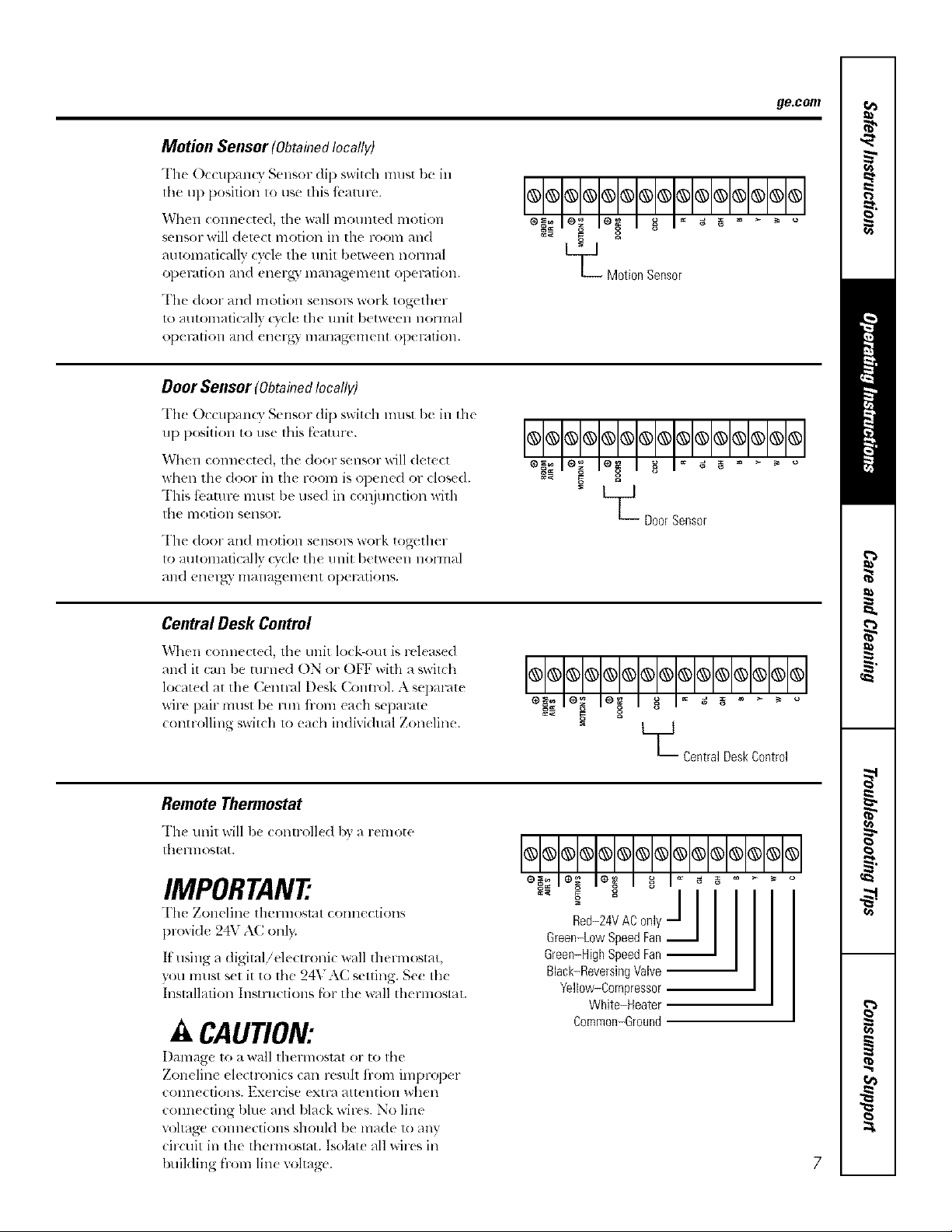
Motion Sensor(ObtahTedlocally)
The Occupan( 3 Sensor di1) switch must be in
lhe up position to use this fi..amre.
When connected, tile wall mounted motion
sensor will detect motion in lhe room and
aulomaticallv cycle th( unil I)etween noHnal
ol)el_dtiOll alld ell( 1-_,3' lllall_t_t_ell]( 111 Ol)eF_?tiOll,
The door and motion sensols work together
u) automatically c}cle the unit b(tween normal
ol)el_/tiOll alld (llerg) lllallag(,lllellt ol)el'dtiOll.
Door Sensor (ObtahTedlocally)
Th_ OccupanQ" Sensor (lip switch must be in tile
up position to use this fbaulre.
When connected, the door sensor will delect
when th( door in tile room is opened or closed.
This tbamre lnusl be use(1 ill col_junetion witll
tile 11]o1]Oll SellSOE
The door and motion sensolY, work together
to automatically cycle the unit between nolmal
_tll(l ellel_)" ill_lllagel_lellt ol)el-_ltiOllS.
ge.com
L_ Motion Sensor
OO@OO®OOOOOOO@O
- L__ DoorSensor
Central Desk Control
When connected, the unit lock-out is released
and il can be turned ON or OFF with a swilch
locat(d at the Cenn-al Desk Colm-ol. A separate
wire pair mtlst be mn iiom each sepalam
controlling switch 1o each individual Zoneline.
Remote Thermostat
The unit will be (ontr_lled by _lremote
theHnosl_t.
IMPORTANT
The Zonelin( thermostat connections
provide 24V A(onl).
It tlSillg a digitalielectroni( wall thel-lllostat,
you must s(t it to the 24VAC setting. Se( the
Installation Instructions l;ar th( _ll thermostat.
A CAUTION:
Damage to a wall lhermostal or to tile
Zoneline electronics can resuh ii-om improper
COlllleCliOllS. Exercise extl-a attention whell
connecting bhle and black wir(s. No line
u)ltage connections should be made u_ any
circuit in the thermostat. Isolate all wires ill
building from line voltage'.
_Central DeskControl
@@@@@@@@@@@@@@@
Black-ReversingVNve
Yellow-Compressor
White-Heater
Common-Ground
7
Otherfeatures ofyourZoneline.
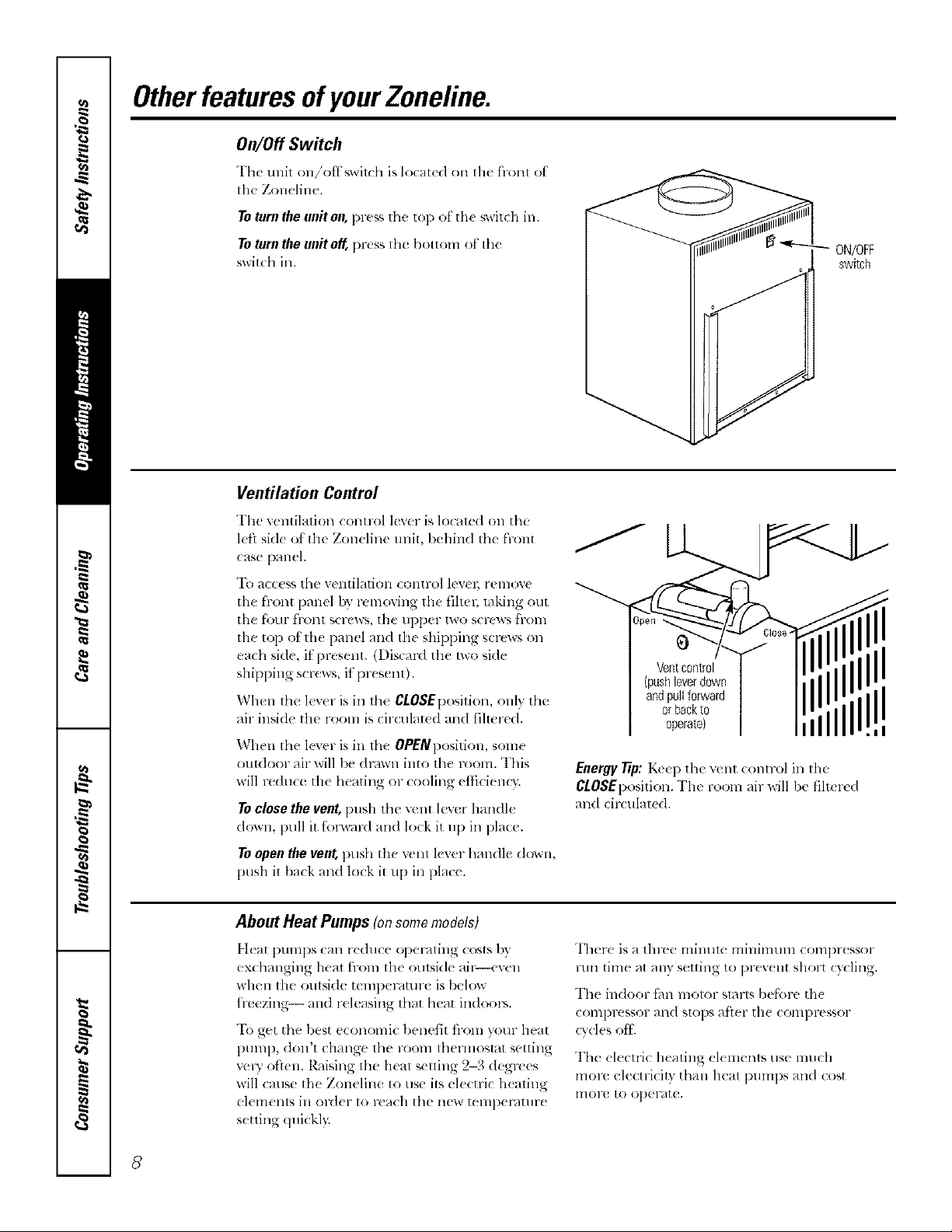
On/Off Switch
Thc unit on/'otf_,wil(h is located on Ill(' front ot
tile Zon( line.
Toturntheuniton,pre_sthe top ot the swit( h in.
ToturntheunitoK l)r(ssthe bottom ot the
switchin.
Ventilation Control
The retaliation conuol lever is localed on the
l(fl sid( of tile Zoneline unit, behind the front
case panel.
To access the ventilation control levm; remove
the front panel by removing the filtel; raking out
the four front screws, the upper two screws fl-om
the top of the panel and the shipl)ing screws on
each side, it present. (Discard the Iwohide
shipping scl*:ws, it present).
When the lever is in the CLOSEposition, onh the
air inside the rooln is circulat_ d and filmred.
When the lever is in the OPENposition, some
outdoor air will lye drown into the room. This
will reduce the heating or cooling etficiem3:
Toclosethevent,[)ush tim vent lever handle
down, pull it t;nl_vard an(I lock it up ill place.
Toopen the vent, push the vent lever handle down,
push it/)ack and lock it u l) ill place.
ON/OFF
Ventcontrol
(push[everdown
andpullforward
orbackto
operatel
Energy Tip: K_e l) the vent COlltr()l ill the
CLOSEl)osition. The room air will be filt_ rtd
and circulated.
switch
II
=i
About Heat Pumps (onsomemodels)
Ileal pumps can reduce opel-,iting costs by
exchanging heat from tile oulside ail_-even
when tile outside temperature is/)elow
h>ezing-- and r(leasing that heat indoors.
"Ik)get the best economic 1)enetit fi-om your heat
Dt]ml), (lon't change the room thelmoslat setting
vcWoften. R_dsing lhe heat selling 2-3 degrees
will cruise tile Zoneline 1o use its electric h(ating
elements in ord(r to reach tile new tempemtmx
s(tting (luickl):
Ther( is a tlm'e minum milfinmln coml)r(ssor
run time at any setting to pr(v(nt short cycling.
The indoor t;m motor slarts belknx, th(
coml)res*or and slops atier tile compressor
cvcl(s eli.
The (lecuic heating elemenls use much
molv electricity than heat l)UmpS and cost
lnoru to oper4te.
8
Careandcleaning, gecom
Turn the Zoneliue off and disconnect the power supply before cleaning.
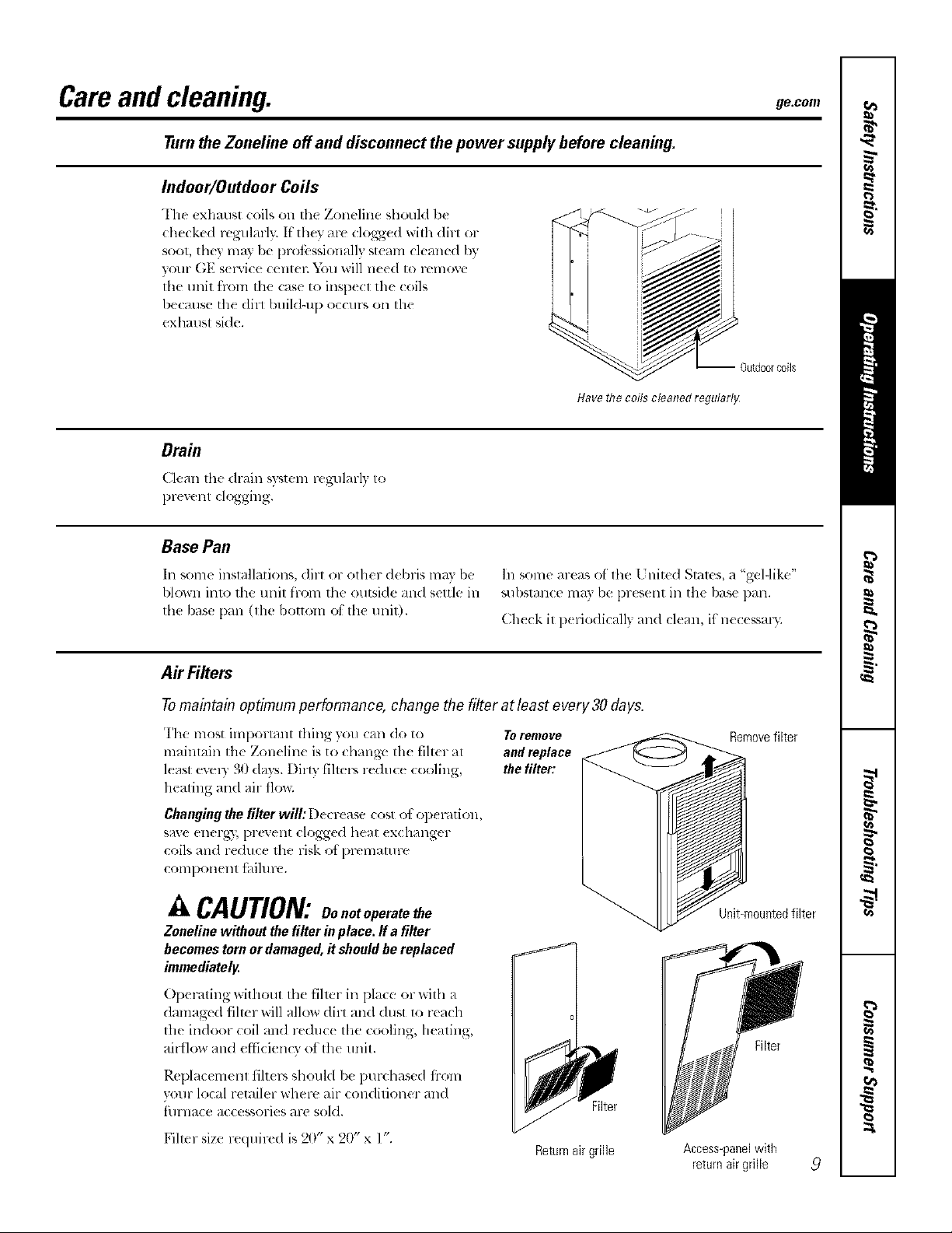
Indoor/Outdoor Coils
The exhaust (:oilson the Zoneline should be
checked regularly. If'they are clogged will_ dirl or
soot, they may l)e prot;._ssionall} steam cleaned by
your GE s(iMce (:ent_ l:D)u will need to remoxe
lhe unit h-ore the case to inspecl the coils
because the dirl buildqlp occurs on the
exhaust side.
-- Outdoorcoils
Have the coils cleaned regularlg
Drain
Clt'ma fl_edrain w_tem re_ulm-ly to
prexent clogging.
Base Pan
In some installations, dirt or olher debris may be
blown into the unit from the outside and settle in
fl_e base l)an 0he bottom of the unit).
In some areas of ll_e 17hired Stares, a "gel-like"
substance may be l)resent in the base pan.
Check it periodically and clean, if"necessal);
AirFilters
Tomaintain optimum performance, change the filter at least every 30 days.
The most important thing you can do to Toremove
maintain the Zoneline is to changt, the filter at and replace
least ev(qy 30 days. Dim fihers reduce cooling, the filter:
heating and air flo_;
Changing the filter will: [)(crease cost el el:){ration,
save energy, prevent clogged heat ex( hanger
coils and reduce the risk ot l)rematu re
coral)orient tbihlre.
A CAUTION:Oo.o,operatethe
Zonelinewithoutthefilterinplace,ffa filter
becomestornordamaged,itshouldbe replaced
immediately.
Operating without the filmr in place or with a
damagv(I filmr will allow dirt an(I dust to reach
the indoor coil an(I re(hlc( the cooling, heating,
airflow and efticien O of the unit.
Removefilter
Unit-mountedfilter
Filter
Rel)lacemenl tilt(rs should b( l)urchased fi-om
vour local retailer where air conditioner and
filrnace accessories are sold.
Fihcr size required is 20" x 20" x l".
Filter
Returnair grille
Access-panelwith
returnair grille
9
 Loading...