

Page 1
0
Safety Instructions ........... 2
Operating Instructions
Air Direction ................ 4
Auxiliary Controls .......... 5-9
Controls .................... 3
Vent Control ................ 4
Care and Cleaning
Air Filters .................. ] ]
Base Pan .................. ] 0
Outdoor Coils .............. l 0
Room Cabinet and Case ...... l 0
Ventilation Fiher . ........... l0
Installation Instru_tions
Electrical Supply ......... 14-16
Installing the Zoneline .... 17, 18
Preparation ................ 12
Replacing an Existing Unit? . . .13
Troubleshooting Tips .... 19, 20
Normal Operating Sounds .... 20
ge.com
Heat Pump Modal 5800
Espar_ol
For a Spanish version of this
manual, visit our _A/ebsite at
g'e.coIl/.
Para consultar una version en
espaflol de este manual de
instrucciones, visite nuestro
sitio de internet ge.com.
Francaise
For a French version of this
manual, visit our _'ebsite at
ge.com.
Pour une version flanqaise de
ce manuel d'utilisafion, veuillez
visiter notre site web ;3l'adresse
ge.com.
©
Consumer Support
Consumer Support . . .Back Cover
Product Registration ...... 21, 22
*¢\hrranty .................. 23
Write the model and serial
numbers here:
Model #
Serial #
Find these numbers on a label
behind the room cabinet on the
base pan.
TINSEA472JBRZ 49-7537-1 01-06 Jfl
Page 2
IMPORTANTSAFETYINFORMATION.
READALLINSTRUCTIONSBEFOREUSING.
_4,WARNING!
Foryour safe_ the information in this manual must be followed to minimize the risk of fire or
explosion, electric shock, or to prevent property damage, personal injury, or loss of life.
_\ "_ SAFETYPRECAUtiONS
fy_ • This Zoneline llltlst be properly
installed in accordance with tile
Installation Instructions before it is
used. See the Installation Instructions
in tile back of this manual.
• Replace immediately all electric service
cords that have become flayed or
otherwise damaged. A damaged power
supply cord must be replaced with a
new power supply cord obtained flom
the mamffacturer and not repaired.
Do not use a cord that shows cracks
or abrasion damage along its length or
at either tile plug or connector end.
• Unplug or disconnect tile Zoneline at
tile fllse box or circuit breaker before
making any repairs.
NOTE:W:e strongly recommend that any
smwicing be performed by a qualified
individual.
Replacing an existing unff?
For details, see the Instalk_tion
Instructions in this manual.
READANDFOLLOWTHISSAFETYINFORMATIONCAREFULLY.
SAVETHESEINSTRUCTIONS
2
Page 3
Aboutthe controlsonyourZoneline. ge.com
= =
_m HIGH
I;_-I:_-ll- 0w
m_ AUTO
TEMP FAR
TEMPCONTROL
@
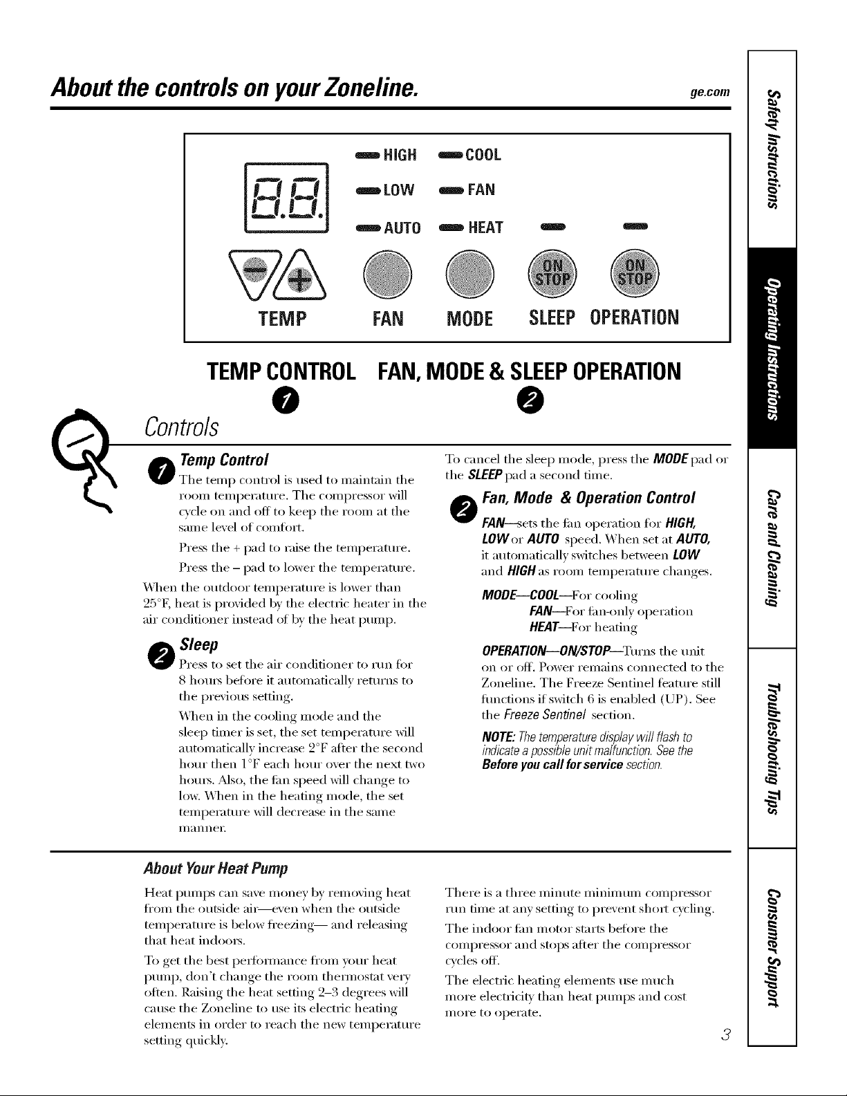
TempControl
The temp control is used to maintain the
I'OOIIl teillpei'attli'e. The coiili)i'essoi" will
cycle on and off to keep the room at the
same level of corot)ft.
Press the + pad to raise the temperature.
Press tile - pad to lower tile temperatm'e.
_,_]/en tile outdoor temi)eratm'e is lower than
25°E heat is provided b)' tile electric heater in tile
air conditioner instead ot by tile heat pump.
Sleep
Press to set the air conditioner to run fi)r
8 l/om_ boil)re it automatically returns to
tile I)revious setting.
_A]/en in tile cooling mode and tile
sleep timer is set, tile set temperatm'e will
automatically increase 2°F after tile second
hour then 1 °F each hour over tile next two
hom_. Also, tile em speed will change to
low. \._l/en in the heating mode, the set
temperatm'e will decrease in tile same
iilannei i
FAN,MODE& SLEEPOPERATION
_nCOOL
_nFAN
"=="HEAT
I !
MODE SLEEPOPERATION
@
To cancel the sleep mode, press the MODEpad or
the SLEEPpad a second tiine.
Fan, Mode & Operation Control
@
FAN--s'ets tile tim operation fin" HIGH,
LOWer AUTO speed. When set at AUTO,
it automatically switches between LOW
and HIGH as room temperature changes.
MODE--COOL--For cooling
FAN--For fim-onl_ operation
HEAT--For heating
OPERATION--ON/STOP--Turnstile unit
on oi" olC[. Power I'eIl/}lins connected to tile
Zoneline. Tile Freeze Sentinel teatm'e still
flmctions if switch 6 is enabled (UP). See
tile Freeze Sentinel section.
NOTE: Thetemperaturedisplaywill flash to
indicatea possibleunit malfunction.Seethe
Before you call for service section.
About YourHeatPump
Heat I)umps can save money by removing heat
fl'om tile outside air----even when tile outside
temi)erature is below fl'eezing-- and releasing
that heat indom_.
To get tile best i)e_tommnce fl'om your heat
i)ump, don't change tile room them/ostat ve_ T
often. Raising the heat setting 2-3 degrees will
cause the Zoneline to use its electric heating
elements in order to reach tile new temperatm'e
setting quickly:
There is a three minute minimum compressor
run time at any setting to prevent shmt cycling.
Tile indoor tim motor starts befln'e tile
COIlll)I'essoI" and stops aJ[teI" tile COIl/l)I'essoI"
cycles off'.
The electric heating elements use much
more electfidtv than heat i)umps and cost
II/OI'e to operate.
3
Page 4
OtherfeaturesyourZoneline mayhave.
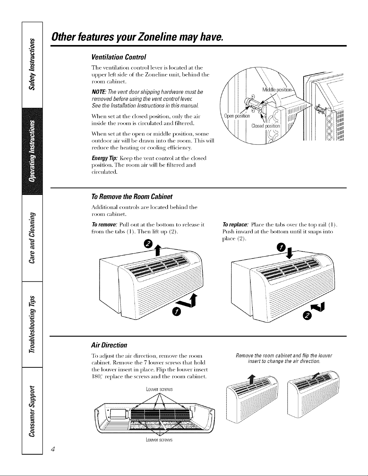
Ventilation Control
The xentilation control lexer is located at the
upper left side of the Zoneline unit, behind the
I'OOIll cabinet,
NOTE:Thevent doorshippinghardware mustbe
removedbeforeusing thevent control lever
See theInstallationInstructionsin this manual.
_,_q_en set at the closed position, onE' the air
inside the room is circulated and filtered.
\,_]_en set at the open or middle position, some
outdoor air will be drawn into the room. This will
reduce the heating or cooling efficiency:
Energy Tip: Kee I) the vent control at the closed
position. The room air will be filtered and
circulated.
ToRemovethe RoomCabinet
Additional controls are located behind the
I'OOIl] cabinet.
To remove: Pull out at the bottom to release it
fl'om the tabs (l). Then lift up (2).
Middlepo_
To replace: Place the tabs oxer the top rail ( l ).
Push imvard at the bottom tmtil it snaps into
place (2).
Air Direction
To a_!iust the air direction, remove the room
cabinet. Remove the 7 louver screws that hold
the louver insert in place. Flip the louver insert
180_ replace the screws and the room cabinet.
Louverscrews
Louverscrews
4
Removethe room cabinet and flip the louver
insert to change the air direction.
Page 5
Auxiliary ControlsonyourZoneline. ge.com
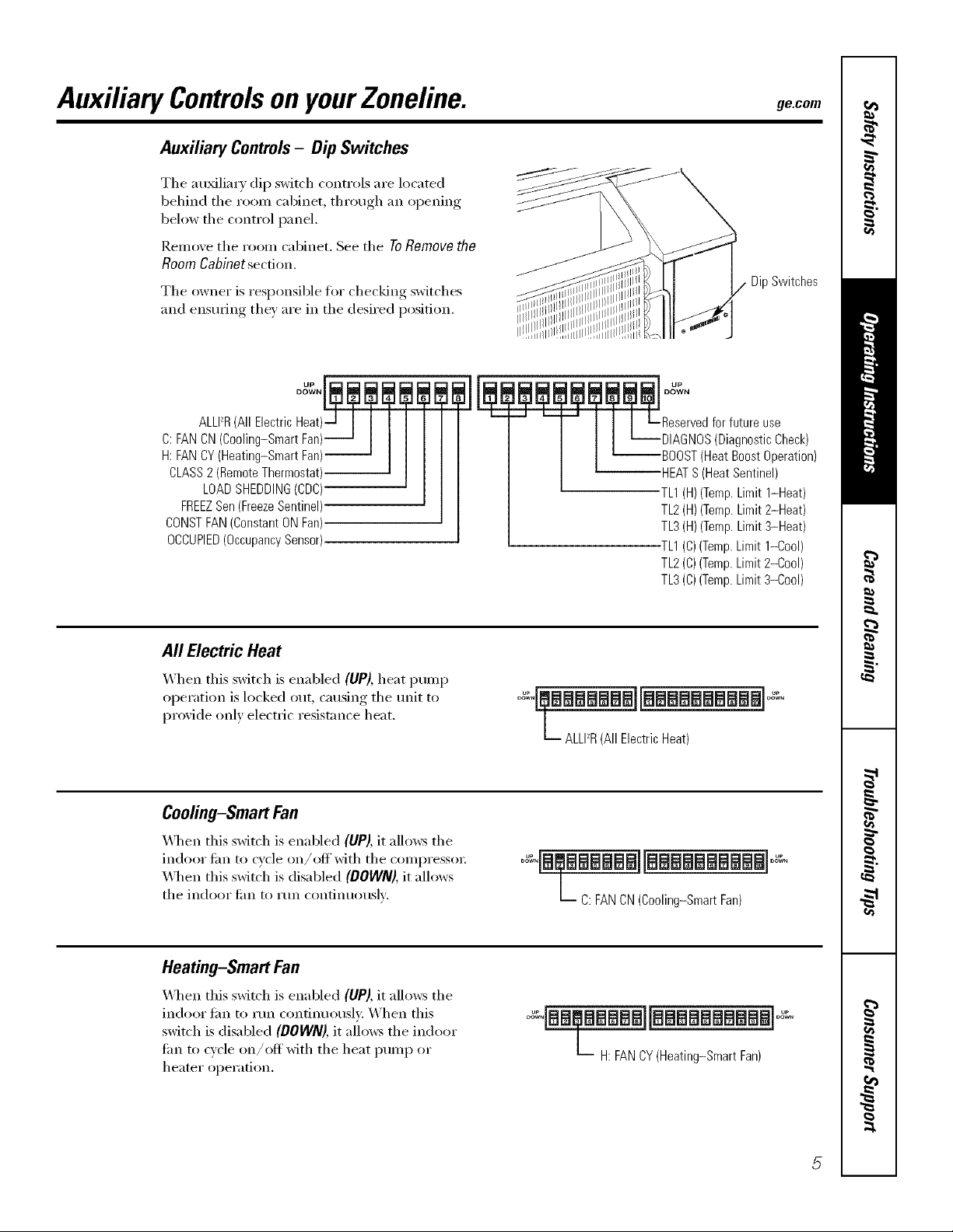
Auxiliary Controls- Dip Switches
The au_lim y dip switch controls are located
behind tile room cabinet, through an opening
below the control panel.
Remove tile room cabinet. See tile ToRemovethe
Room Cabinet secdon.
Tile owner is responsible for checking switches
and ensucing tile)' are in tile desired position.
DOWN
UP
DipSwitches
C:FANCN(Cooling-SmartFan)
H:FANCY(Heating-SmartFan)
CLASS2(RemoteThermostat)
LOADSHEDDING(CDC)
FREEZSen(FreezeSentinel)
CONSTFAN(ConstantONFan)
OCCUPIED(OccupancySensor)
I1I
All Electric Heat
X._hen this switch is enabled (liP), heat pump
operation is locked out, causing tile unit to
proxide only electric resistance heat.
Cooling-Smart Fan
_._]/en this switch is enabled (UP), it allo_vs tile
indoor tim to cycle on/offwith tile compresso_:
X&]/en this switch is disabled (DOWN),it allows
tile indooi" tilil to Illn contintlOtlslv;
DIAGNOS(DiagnosticCheck)
BOOST(HeatBoostOperation)
HEATS(HeatSentinel)
TL1(H)(Temp.Limit 1-Heat)
TL2(H)(Temp.Limit2-Heat)
TL3(H)(Temp.Limit3-Heat)
TL1(C)(Temp.Limit1-Cool)
TL2(C)(Temp.Limit2-Cool)
TL3(C)(Temp.Limit3-Cool)
0 ;,!¢mmmmmmmlimmmmmmmmam]o,+°
L ALLPR(All ElectricHeat)
0o+,+"mUamammmmlImmmmmammmm]o_o
L C: FANCN(Cooling-Smart Fan)
Heating-Smart Fan
_._l/en this switch is enabled (UP), it allows tile
indoor tim to run continuously. When this
switch is disabled (DOWN), it allows tile indoor
tim to cycle on/off with tile heat pump or
heater oper;ition.
mmmmmiimmmmmmmmm+i
L H: FANCY(Heating-SmartFan)
Page 6
Auxiliary controlsonyourZoneline.
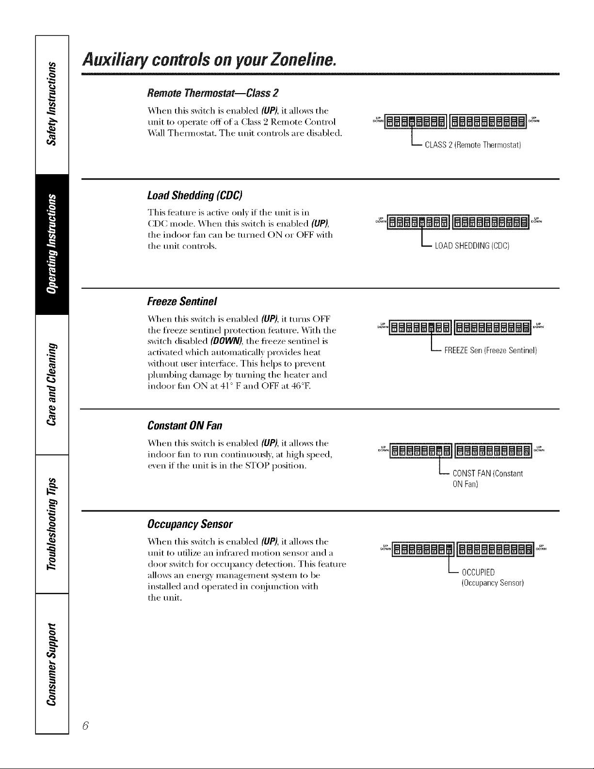
Remote Thermostat--Class 2
_4q_en this switch is enabled (UP), it allows the
unit to operate off of a Class 9 Remote Control
Wall Them_ostat. The unit controls are disabled.
LoadShedding(CDC)
This teatm'e is active onE' if the refit isin
CDC mode. When this switch is enabled (liP),
the indoor tim can be turned ON or OFF with
the tmit controls.
FreezeSentinel
\&l_en this switch is enabled (UP), it turns OFF
the fl'eeze sentinel protection featuI'e. With the
switch disabled (DOWN), the freeze sentinel is
acfi\_ted which automatically provides heat
without user inte_ti_ce. This helps to prevent
plumbing damage by turning the heater and
indoor tim ON at 41° F and OFF at 46°K
L CLASS2 (Remote Thermostat)
L LOAD SHEDDING(CDC)
L FREEZESen (FreezeSentinel)
Constant ON Fan
X_q_en this switch is enabled (UP), it allows the
indoor tim to rim confinuousl_, at high speed,
exen if the trait is in the STOP position.
OccupancySensor
_l_en this switch is enabled (UP), it allows the
unit to utilize an infl'ared motion sensor and a
door switch fin" occupancy detection. This timtm'e
allo_:s an energy' management system to be
installed and operated in coqitmcfion with
the tmit.
L CONST FAN (Constant
ONFan)
L OCCUPIED
(Occupancy Sensor)
Page 7
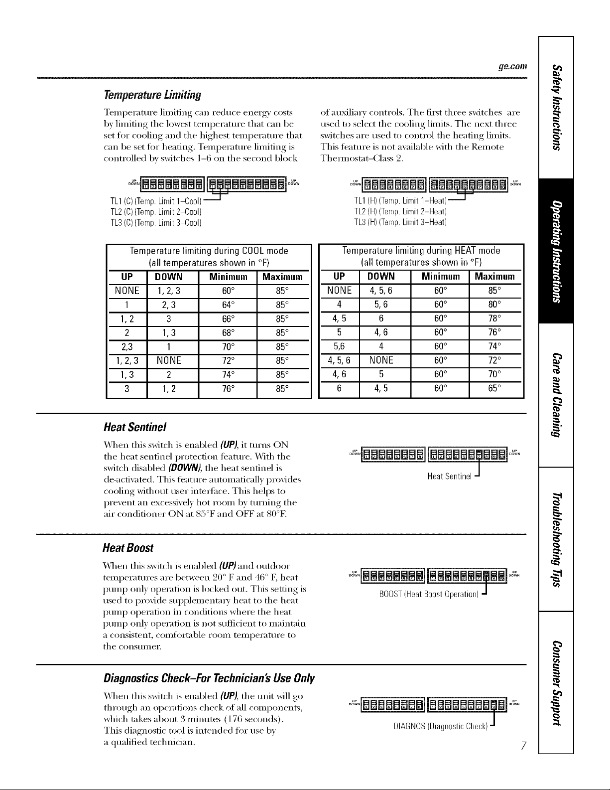
Temperature Limiting
Temperature limiting can reduce energy' costs
by limiting the lowest temperature that can be
set fl)r cooling and the highest temI)erature that
can be set fin" heating. Temperature limiting is
controlled by switches 1-6 on the second block
TL1(C)(Temp.Limit1-Cool)___.1"
TL2(C)(Temp.Limit2-Cool)
TL3(C)(Temp.Limit3-Cool)
ge.com
of au_lia_ y controls. Tile fit_t three switches are
used to select the cooling limits, The next three
switches are used to control tile heating limits,
This teature is not available with tile Remote
Them_ostat-Class 2.
0oqaelelee e ele j! mW alo ,
TL1(H)(Temp.Limit1-Heat)_
TL2(H)(Temp.Limit2-Heat)
TL3(H)(Temp.Limit3-Heat)
Temperaturelimiting during COOLmode
(all temperatures shown in °F)
UP DOWN Minimum Maximum
NONE 1,2, 3 60° 85°
1 2,3 64° 85°
1,2 3 66° 85°
2 1,3 68° 85°
2,3 1 70° 85°
1,2, 3 NONE 72° 85°
1,3 2 74° 85°
3 1,2 76° 85°
Heat Sentinel
_,_]/eil this switch is enabled (UP), it turns ON
tile heat sentinel protection feature. _,_]tl/tile
switch disabled (DOWN), tile heat sentinel is
de-actiwated. This teature automatically provides
cooling without user interlhce. This helps to
prevent an excessively hot room by turning tile
air conditioner ON at 85°F and OFF at 80°E
Temperature limiting during HEATmode
(all temperatures shown in °F)
UP DOWN Minimum Maximum
NONE 4,5, 6 60° 85°
4 5,6 60° 80°
4, 5 6 60° 78°
5 4,6 60° 76°
5,6 4 60° 74°
4,5, 6 NONE 60° 72°
4, 6 5 60° 70°
6 4, 5 60° 65°
oqaaaaaaaaliaaaaaa @l ,
HeatSentinelJ
Heat Boost
_,_q/en this switch is enabled (UP) and outdoor
temperatures are between 20 ° F and 46 ° F, heat
pump only operation is locked out. This setting is
used to provide SUl)l)lementm T heat to tile heat
pump operation in conditions where tile heat
pump only operation is not sufficient to maintain
a consistent, coi/ltOrtable i'ooi/l telill)ei'attli'e to
tile ('onstllllei;
DiagnosticsCheck-For Technician'sUseOnly
_,_q/en this switch is enabled (UP), tile refit will go
through an operations check of all components,
which takes about 3 I//intltes (176 seconds).
This diagnostic tool is intended fin" rise bv
a qualified technician.
.....o.[aaaaaaaallaaaaaaa al
BOOST(HeatBoostOperation)-]
DIAGNOS(DiagnosticCheck)J
Page 8
Auxiliary controlsonyourZoneline.
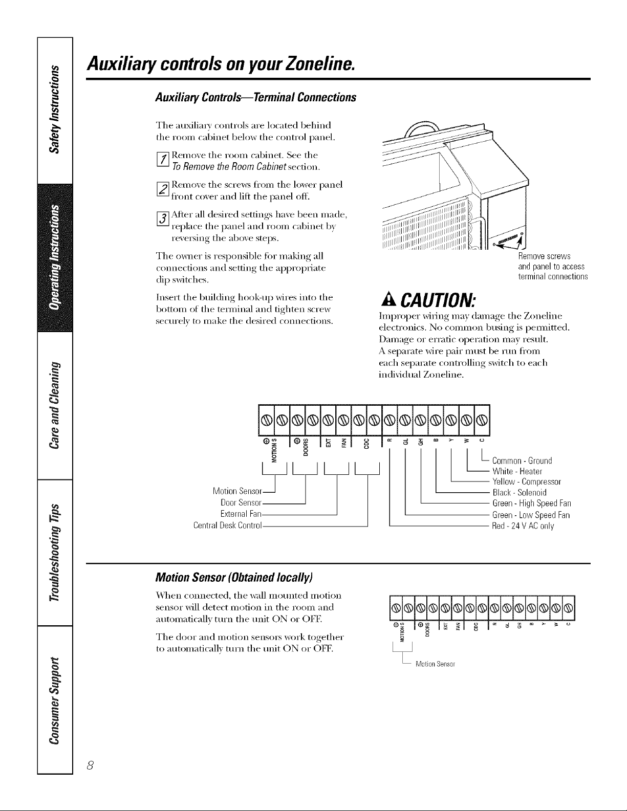
Auxiliary Controls--Terminal Connections
The au_lia_ T controls are located behind
the roon/cabinet below the control panel.
_] I_emove the room cabinet. See the
ToRemove the Room Cabinet secdon.
[_ Remoxe the screws fl'om the lower panel
fl'ont coxer and lift the panel off.
_]/Sdier all desired settings ha_e been made,
replace the panel and room cabinet b,x
reve_ing the above steps.
The owner is responsible fi)r making all
connections and setting the appropriate
dip switches.
Insert the building hook-up wires into the
b(>tt(>m (>_ the temdnal and tighten screw
secm'elv to make the desired connect.ions.
Remove screws
and panel to access
terminal connections
A CAUTION:
Improper wiring may damage the Zoneline
electronics. No common busing is pemfitted.
Damage or erratic operation may result.
A separate wire pair must be mn fl'om
each separate controlling switch to each
individual Zoneline.
o
Door Sensor
Motion Sensor_-] L_ L_ L_
External Fan
Central Desk Control
o
Motion Sensor(Obtainedlocally)
_,_]_en connected, the wall motmted motion
sensor will detect inofion in the room and
automatically mrn the trait ON or OFF.
The door and motion sensm_ work together
to ;mtomaticallv turn the trait ON or OET.
o
I L common- Ground
White - Heater
-- Yellow - Compressor
Black- Solenoid
Green - High Speed Fan
Green- Low Speed Fan
Red- 24 V AC only
o
Motion Sensor
8
Page 9

Door Sensor (Obtained locally)
_]/en connected, tile door sensor will detect
when tile door in tile i'OOill w;is opened or
closed. This teatm'e must be used in coI_junction
with tile motion sensor:
Tile door and i/lotion sensoi3 work together
to autonmticallx tm'n tile refit ON or OFE
External Fan(Obtainedlocally)
X4]/en connected, an auxiliary or external tim
can be controlled with tile indoor tim motor
on the Zoneline, Com_ections provide 94 V AC
to energize a remote relay, turning on the
external tim.
Central Desk Control
ge.com
_ leo IS _l o_ I _ _ _ ° _ _ °
g g
_DoorSensor
_ ExternalFan
X_]/en com_ected, tile refit can be turned ON
or OFF with a switch located at tile Central
Control Panel. A separate wire pair inust be
run fi'om each separate controlling switch to
each individual Zoneline.
Remote Thermostat
X_q/en connected, tile refit _fill be controlled
bv a i'elllote thermostat.
NOTE'The number 4 dip switch must be in tile
enabled (UP) position to activate tile remote
them_ostat, (See the installation instructions
supplied with tile remote them_ostat).
IMPORTAN7?
Tile Zoneline them_ostat connections
provide 24 V AC only
If using a digital/electronic wall them_ostat,
you must set it to tile 24 V AC setting.
See tile Installation Instructions for tile
wall them_ostat.
hi®®®®®®®l®l®l®l®J;;l®
g
_CentraIDeskControi
**q;H;l*lq;I.Iq.lq
z m
Red 24VAConly
o
Green-LowSpeedFan
Green HighSpeedFan
Black-Solenoid
Yellow Compressor
White- Heater
CommonGround
CAUTION:
Damage to a wall them/ostat or to tile
Zoneline electronics can result fi'om improper
connections. Special care must be used in
cmmecting blue and black wires. No line w)ltage
connections should be made t() any circuit.
Isolate all wires in building fl'om line w)ltage.
Page 10

Careand cleaning.
Room Cabinet and Case
Turn the Zoneline otI and disconnect the
power supply:
OutdoorCoils
The coils on the outdoor side of the Zoneline
should be checked regularly. If they are clogged
with dirt or soot, they may be protessionally
steam cleaned, a service a\_filable through your
GE se_Mce outlet. You will need to remove the
unit to inspect the coils because the dirt
build-u I) occm5 on the inside.
To clean, use water and a mild detergent.
Do not use bleach or abrasives. Some commercial
cleane_ may damage the plastic parts.
Coils
Grille
Cleat?the outside coils regularly.
Base Pan
In some installations, dirt or other debris may be
blown into the unit fl'om the outside and settle in
the base pan (the bottom of the unit).
Ventilation Filter
If the ventdoor isopen,clean the ventfilter twice a year
or as required
TurntheZonehbeoff beforecleaning
Toremove the ventfilter:
• Remove the room cabinet. See the ToRemove
the Room Cabinet section.
• Rem_we the four scre_vs securing the unit
flanges to the case.
• Slide the unit from the wall case.
• Grasp the vent filter tab and pull the filmr Otlt
by sliding it to the right.
In some areas ot the United States a 'ijell-like"
substance may be seen in the base pan.
Check it periodically and clean, if necessar}:
Toclean the vent filter:
• Run water through the filter fi'om the
back side.
• D_y thoroughly before replacing.
Page 11

Tomaintain optimum performance, clean the filters at least every 30 days.
Air Filters
m_
Toremove the air filters:
ge.com
2Air filters
Pullup
Dirly filter--Needs cleanflTg Clogged filter--Greatly
reduces cooling, heating
and airflow.
Turnthe Zoneline offbefore cleaning.
The most important thing you can do to
maintain the Zoneline is to clean the filter
at least every 30 days. Clogged filte_ reduce
cooling, heating and air flow.
Keeping these filters clean will:
• Decrease ('()st of operation.
• Save energy:
• Prevent clogged heat exchanger coils.
• Reduce the risk of prematm'e component
fifilm'e.
Toclean the air filters:
• Vacuum off' the heavv soil.
•Rtm water through the filte_.
• Dry thoroughly befi)re replacing.
Toreplace the air filters:
Pushdown
CAUtiON: Oonot operatethe
Zonelinewithout the filters inplace. Ira filter
becomestorn or damagedit shouldbe replaced
immediately.
Operating without the filte_s in place or with
damaged filte_ will allow dirt and dust to reach
the indoor coil and reduce the cooling, heating,
airflow and efficiency of the refit.
Replacement filte_ are awfilable fl'om yore"
salesperson, GE (leale_; GE Service and Parts
Center or authorized Customer Care '_se_'icers.
11
Page 12

Installation
Zoneline Air
Instructions
Conditioners
I Ouestions?Call800.GE.CARES(800.432.2737)orVisitour Website at: ge.com I
BEFORE YOU BEGIN
Read these instructions completely and carefully.
• IMPORTANT - S_,,ethese
instructions for local inspector's use.
• IMPORTANT - Obse,,e_,.
governing codes and ordinances.
• Note to Installer _ Be sure to leave these
instructions with the owner.
• Note to Owner _ Keep these instructions tor
flmu'e reference.
• Proper installation is the responsibility of the
installer.
• Product thilure due to improper installation is not
covered trader the _'arrantv.
TOOLS YOU WILL NEED
Phillipsscrewdriver
IMPORTANT ELECTRICAL
SAFETY-READ CAREFULLY
CAUTION:
• Follow the National Electrical Code (NEC) or local
codes and ordinances.
• For personal safety, this Zoneline must be properly
grounded.
• Protective devices (fuses or circuit breakers)
acceptable for Zoneline installations are specified
on the nameplate of each unit.
• Do not use an extension cord with this unit.
• Aluminum building wiring may present special
problems--consult a qualified electrician.
• When the unit is in the STOP position there is still
voltage to the electrical controls.
• Discmmect the power to the unit before
servicing by:
1 Removing the power cord (if it has one) from
the wall receptacle.
OR
2 Removing the branch circuit fuses or turning
the circuit breakers off at the panel.
ZONELINE COMPONENTS
Exteriorgrille/Ic
Wall
* Shipped with flTe Zoneline unit
_ Check the "Essential Elements" list on flTe unit
bmcabinet *
12
Page 13

Installation Instructions
REPLACING AN EXISTING UNIT?
Checkthe "Essential
Elements"labelfor
importantinformation.
Use the correct wall case
This unit is designed to be installed in a GE plastic or
insulated metal wall case. This minimizes condensation
from fimning on the room side of the case.
If the current wall case is not insulated, you can reduce
the possibili b' of condensation fimning 1)yinst;flling
insulation kit ILM(901 I,, a\:filable where you purchased
the unit.
Use the correct outdoor grille
You should use the outdoor grilles shown on the
"Essential Elements" label on the top of the unit.
• If an existing grille is not replaced, capaci_' and
efficiency will be reduced and the unit may tail to
operam propedy or fifil prematurely: A deflector kit,
I_K40, may be used with grilles that were not designed
fin" w>ur new GE Zonelines. The ]_M(40 contains air
cleflectots and gaskets that mount to the trait m direct
the hot exhaust air away fl'om the air intake to allow
the unit to flmction properl> The grille inust have
a 65% minimum fl'ee area.
• Any vertical deflectors in the existing rear grille should
be reilloved to decrease condenser air recirctllation
which can cause the trait to "short-cycle" and lead
to pi'ei/latui'e COll/ponent Jilihlre.
13
Page 14

Installation Instructions
230/208 VOLT ELECTRICAL SUPPLY
HOW TO CONNECT
1 Remove the reran cabinet.
2 Connect to electrical power.
3 See the special instructions below fin" applicable
supply voltages.
4 Reinstall the room cabinet.
A power supply kit must be used to supply power to fl_e
Zoneline trait. The apl)ropfiate kit is detemfined by the
voltage, the means of electrical connection and the
amperage of the branch circuit.
Power supply kit
C(mnecfions of 208 or 230 volt circuits may be with a
power SUl)pl ) kit or a jtmction box kit.
All wiring, including installation of tile receptacle,
must be in accordance with the NEC and local codes,
ordinances and regulations. I,ocal codes may require
the use of an arc tault or leakage current detection
device on the power cord. Be stu'e to select the
correct cord fin" wmr installation.
Power cords may include an arc fault interruption or
a leakage current detection interruption device. A
test mad reset button is provided on the plug case or
the inline case. The device should be tested on a
periodic basis by first pressing the TEST button and
then the RESET button. If the TEST button does
not trip or if the RESET button will not stay engaged,
discontinue use of the Zonelhae and contact a
qualified service technician.
COllllectioll.
Order Kit RAK4002B for 230/208 xolt direct I
IF USING AN ELECTRICAL
SUBBASE
230/208 xolt models ma) be installed using one of
the fi)llowing electrical subbases:
Branch Circuit and Proper GE
UnitAmperage Bating Subbase Kit
15 ]L_IL204D 15P
20 ]L_IL204D20P
30 RAIZ,204D30 P*
*Not approved {i)r use ou, 7000 BTU models.
Electrical subbases provide an enclosm'e tot direct
cmmection or enclosed receptacles. The subbase kit
includes the power cord.
I
I
© © @
Tandem Perpendicular Large Tandem
15Amp. 20Amp. 30Amp.
230/208volt receptacle configuration.
Branch Circuit and Proper GE Power Cord
UnitAmperage Bating with LCDIDevice
15 RA1(3153
20 1_I(24203
30 ],L&K3303*
':Not approxed tor use on 7000 BTU models.
The instructions provided with the selected subbase kit
must be carefifllv tollowed. It is the responsibility of the
installer to ensm'e tile connection of components is
done in accordance with these instructions and all
electrical codes.
14
Page 15

Installation Instructions
265 VOLT ELECTRICAL SUPPLY
/k WARNING:
Connection of this 265 V AC product to a branch circuit
MUST be done b) direct connection in accordance with
the Natkmal Electric (;()de, Plugging this unit into a
building mounted exposed receptacle is not permitted
b) code,
These models must be installed using the appropriate
GE power suppl} kit ti)r the branch circuit amperage
and the electrical resistance hearer wattage desired,
See the POWER CONNECTION (;HART in these
Installation Instructions. One of the tbllowing
installation methods must be used:
A Elecu'ical subbase kits are available to provide a flexible
enclosm'e for direct c(mnecfion,
Branch Circuit and Proper GE Power
UnitAmperage Rating Subbase Kit SupplyKit
15 ILM4204E 15 ILM(5172
20 ILM4204E20 1,LM(5202
30 I,LM4204E30 1LM(5302
The instructions pr_Mded wifll the selected subba_ kit must
be cm'efld b ti)llo_d, It is the responsibilit) of the installer
to ensIlre the connection of colrll)onents is done in
accordance with these instructions and all elecu'ical codes,
B For direct c(mnecdon to branch circuit wi_Jng inside the
provkted j unction box without using a subbase kit, cut
the cord, strip the wire ends and c(mnect as fi)llo_:s,
[] REMOVE JUNCTION BOX
1 Remove thejmlction box cover by taking out the
fl'ont Ibm" screws.
2 Remove thejmlction box by taking out the top rear
screwy. Note how the tab on the lower right corner
of the j unction box serves to hold the side in place.
This will hel I) when the box is being reinstalled.
The cord will be coiled up inside the junction box,
[] CUT AND STRIP THE CORDSET
1 Remove the cordset from the power supply kit.
Measure 6" down the cord fl'om where it emerges
fl'om the back of the nylon plastic connector
and cut the cord through at tiffs point.
2 Carefifllv remove 3" of the cordset insulation
so as to expose the three insulated wires.
3 Strip 3/4" of the insulation away at the end
of each of the three wires (I,1, Neutral and
Grotmd). Plug the connector fidlv into place
in the trait mating connector. Be sure the
locking robs at the sides are engaged.
3/4"
NOTE: Order Kit RAK4002(_'\ to enable a quick
disconnect inside tim jtmction box.
I
[] ATTACH CONDUIT
1 Lrse the rotmd knockout at tim bottom of tim
junction box to attach conduit coming fl'om tim
branch circuit. Remove tim knockout, attach tim
conduit and bring wires into tbejtmction box.
I,eave 6" of wire fl'ee at the end oI the conduit
to allow connections to be II/ade.
.o.-"
_-"_
I
ff
box cover
Junction-
box
_¢"" ;--j'" <---Conduit
If a filse and fllseholder are to be used, the
knockout at the top of the box is fi_r mortaring
a Buss Fusel_oldet; Be sure the filse and filseholder
are of the same rating as the branch circuit.
I,eadwires at the fllse can be either soldered in place
or am_ched using UiAisted 1/4" temale (receptacle)
ci'ilil l) connectoi3.
15
Page 16

Installation Instructions
265 VOLT ELECTRICAL SUPPLY
[] REINSTALL JUNCTION BOX
• Reinstall the junction box by engaging the tab at the
lo_vr rea_; aligning the screw hole at the top and
driving the one screw tmfil sectlre. Be stlre that all
wire leads are inside the box and not pinched
between the box and the unit. The green insulated
grotmd wire fl'om the unit MUST be connected to
the branch circuit ground wire.
Make all wire connections by using appropriate
UIAisted electrical connectcn_ and techniques
(black to black, whim to white and green to green).
POWER CONNECTION CHART
230/208 Volt
Power
Supply Kits
RAK3153
RAK3203
RAK3303*
Wall Plug
Configuration
T;111 d elll
Perpendicular
i,arge Tandem
[] REINSTALL JUNCTION
BOX COVER
1 Careflfllv rock all wires and
connections back inside the
.junction box. Be sure there
are i1o loose COllllectiolis oI"
stray tminsulated wires
exposed.
2 Place the junction box cover
in place. Replace the two
sci'ews reliloved earlier alld
tighmn secmelv:
3 Discard the unused portion of the plug and
the cordset.
Circuit Protective Device
20 Amp Tilne Dela_ Fuse or Breaker
I 15 Amp Time Delay Fuse or Breaker
30 Amp Tilne Delay Fuse or Breaker
Heater Wattage
@ 230/208 Volts
2.55/2.09 KW
3.45/2.82 KW
5.00/4.10 KW
265 Volt
Power
Supply Kits
RAK5172
RAK5202
RAK5302*
* Not recommended for use on 7000 BTUH units.
Wall Plug
Configuration
Does Not Apply
Does Not Apply
Does Not Apply
20 Alnp Time Delax Fuse or Breaker
I 15 Amp Time Delax Fuse or Breaker
30 Amp Tilne Delay Fuse or Breaker
Heater Wattage
Circuit Protective Device @ 265 Volts
2.:7: K\,V
3.45 KW
5.0 KW
16
Page 17

Installation Instructions
INSTALLING THE ZONELINE
[] INSTALL THE WALL CASE AND
EXTERIOR GRILLE
1 The l_kg71 series or ILkg77 _;_11 case must be
properly installed per instructions packed with
the case,
2 Remove tile corrugated stiffener and tile outdoor
protective panel. Use the slit in the outdoor panel
as a handhold and push out.
Pro
panel
Stiffenel
3 Install the exterior grille fl'om the room side
fi_llowing instructions packed with the grill.
[] PREPARE THE ROOM CABINET
1 (_arefull_ remoxe shiplfing tripe if'there is am fl'om
the room cabinet and _ent do(n:
Shipping
tape
2 Remoxe the shipping screw/clamp from the ",ent
do(n; if present.
/
Removeshipping
screwandclamp
/ if present
Insulated Wall Case
This unit is designed to be inst;dled in a
GE plastic or an insulated steel wall case. This
minimizes condensation fl'om fimning on the
room side oI the case.
The I_Lkg71 series wall cases are insulated. Insulation
kit ILM(901 I, is available fin" rise with IL_B77 or
existing uninsulated wall cases when needed.
NOTE: For installation with a subbase, see the
instructions packed with that kit.
3 Remo_e tile room cabinet b) pulling it out at tile
bottom to release it (1), then lift it up to clear the
rail alow,_ the trait top (2).
17
Page 18

Installation Instructions
[] iNSTALL THE UNiT iNTO THE
WALL CASE
Slide the unit into the wall case and secure with ibm"
scre_s through the unit flange holes.
NOTE: There are several extra holes in the unit side
flanges for installation in wall cases other than GE.
To avoid damaging the flange insulation, the installer
should use an awl or other shmp tool to puncture the
insulation in the appropriate holes heft)re installing
the attachment screws,
[] REPLACE THE ROOM CABINET
Reinstall the room cabinet by hooking the top oxer
the rail ahmg the unit top (l), then I)ushing, it in at
the bottom (2).
18
Page 19

Before YouCall ForService... gecom
Troubleshooting -tips
Problem Possible Causes What ToDo
Zoneline does The refit is * Make sure tile Zoneline plug is pushed completely
notstart unplugged, into tile outlet.
The fuse is blown/circuit * (_he(k tile house fllse/circuit breaker box and replace
breaker is tripped, tile filse or reset tile breaker:
The unit is waiting for • This is nomlal, Tile Zoneline will start again after
the compressor overload it resets,
protector to reset.
Power failure.
• There is an autoulatic delay stair teature that Inay not
allow tile trait to start, after power is restored and tile
trait is tin'ned back on, fin" approximately 30 seconds.
• There is a protective time delay (up to 3 minutes) to
prevent tripping ot tile compressor overload. For this
reason, the unit may not start nom/al heating or cooling
fi)r 3 ininutes after it is turned back on.
The current interrupter
device is tripped.
• Press tile RESETbutton located on tile power cord plug
or tile box near tile pltlg.
• If the RESETbutton will not stay engaged, discontinue ttse
of the Zoneline and contact a qtalified sexaice technician.
Zoneline does not cool
or heat as it should
Indoor airflow
is restricted.
Outdoor airflow is
restricted or recirculated.
The temp control may
not be set high enough.
The air filter is dirty.
The room may have
been hot or cold.
Outdoor air is
entering the room.
• Make sure there are no curtains, blinds or flu'niture
bh)cking tile fl'ont ot tile Zoneline.
• Make stu'e tile rear grille is not restricted. This can cause
tile unit to cycle off due to tile compressor overload.
• Outdoor grille umst have a ulininmlu of (35% fl'ee area.
Non-GE grilles inay be too restlJctive fi)r proper
perfi)i_n/ance. (]onsult your salespei_on fi)I" assistance.
• Turn the control to a lower or higher setting.
NOTE: The temperature/imlter may be/imlting the temperature range.
• Clean tile filter at least evely 30 da)s.
See tile OporatiRg hTstructions section.
• When tile Zoneline is fiI_t turned on you need to
allow tiule tor tile I'OOUI 10 COO1 down oi" l_';llIlÀ tlI),
• Set tile vent control to tile C/OSEposition.
Burning odorat the start Dust is on the surface • This can cause a "burning" odor at tile beginning of
of heating operation of the heating element, tile heating operation. This odor should quickly lade.
The air is not always The heat pmnp is not • This is nomlal. The heat pump will produce wmm air
cool or hot during producing hot air. but not as hot as air produced when tile highei_cost
operation electric heat is used.
The fan switch may be
set at continuous fan
• This causes tile tim to blow roou/ temperature air
even when the compressor or heater cycles off.
The continuous air movement provides better
overall temperattu'e control.
19
Page 20

Before YouCall ForService...
Troubleshooting -tips
Problem Possible Causes What To Do
The air does not feel The heat pump alone * Use tile Electric Heat Option. This turns off tile
warm enough during produces air that feels heat l)mnl _ and warms with electric heat only.
heating operation cooler thm_ desired. NOTE: Use of this option Wl//result In increased energy
consumption.
Temperaturedisplay The compressor may
flashes have failed.
Thingsthatare normal
Normal Operating Sounds
PING! POP!
"CLICK"
DRIP
6
• Set tile mode control to STOP and then restart tile
unit. If tile flashing light reappears within 30 minutes,
call fin" service.
You may hear a pinging noise caused by water being
picked up and thrown against the condenser on
rainy da):s or when the humidi U is high. This design
teatm'e helps remove moisture and improve
efficiency.
Ybu max hear relax_ click when tile controls cxcle
on and off or are a(!iusted to change the room
temperature.
X&_aterwill collect in tile base pan dtwing high
humidit_ or on raim days. Tile water may oxertlow
and drip fl'om tile outdo(>r side of tile refit.
2O
WHIR./
COMPRESSOR
PROTECTION
Tile indoor tim runs continuously when tile refit is
operating in tile cooling mode, unless tile lira switch
behind tile room cabinet is set at tim cycle (up).
This will cause tile tim to cycle on and off with tile
compress(n: You may also hear a t_lll noise stop
and stm*.
_m may notice a few minutes delay in starting if you
try to restmX the Zoneline too soon after turning it
off or if you a(!iust the themaostat right atter the
compressor has shut off. This is due to a built-in
restart protector fl)r tile compressor that causes
a S-minute delay:
Dm'ing tile deti'ost cycle, both indoor and outdoor
rims stop and tile compressor will operate in tile
cooling illode to i'eil/ove ti'ost J[i'Oiil tile O/lt(looI" coil.
_Mter defi'ost, tile trait will restart in electric heat to
quickly warm tile room to tile desired comfort level.
To protect tile compressor and prevent short
cycling, tile refit is designed to rtm fi)r a minimum
of 3 n/inutes, alter tile compressor starts at am'
themaostat setting.
Page 21

Please place in envelope and mail to:
General Electric Company
Warranty Registration Department
P.O. Box 32150
Louisville, KY 40232-2150
,_ Ct/t here
21
Page 22

Consumer Product Ownership Registration
Deal Customer:
Thank you for purchasing our product and thank you for placing your confidence in us.
_A/eare proud to haxe you as a customer'.
Follow these three steps to protect your
Complete mid mail
your Constuner
Product Owuership
Registration today.
t lave the t)cacc o/
mind of kin)wing we
can contact you in
th( tmlikely (wnt o]
a sa/_'ty modi/i_ ation.
new appliance investment:
:\llcr mailing the
registration below,
store this doclllnCllt
in a sale' place. It
COlltains ill{_)rlIlatJOll
you will m'cd should
_r_)_ require service.
Our service number is
800.GE.( 2\I(ES
(800.432.2737).
Model Number Serial Number
I I I I I I
Important: If you did not get a registration card with your
product, detach and return the form below to
ensure that your product is registered, or register
online at ge.com.
{_{_}t(t VO/IF Owner's
Mamlal careful\.
It will help you
operate your new
appliance properly.
, I
,_.- Cul ll_r<
Consumer Product Ownership Registration
Model Number Serial Number
M*: Ms. M_s. Mi__,
Fir"l I I Lasll
Name I I I I I I I I I Nanle I I I I I I
S[rc(!l [
Addr<ss I I I I I I I I I I I I I I I I I I I I I I I I
#I I I I I I I I I _l.a,,\,l, lre.'
lhie Placed
_.l.l,.rl ,, II,, II , , ,
22
Monlh
GE Consumer & Industrial
Appliances
General Electric Compan U
Louisville, K¥/40225
ge.com
* Please provide your e-mail address to receive, via e-lnail, discounts, special otlbrs and other
important communications fl-om GE Appliances ((;EA).
Check here if you do not want to r(_ceiv(_communications from (;EA's caretilllv sd(_cte(1
parmer_,.
FAIl: RE T() C()MPI ETE AN[) RETI RN TttlS CARD DOES NOT DIMINIStt 5X)I R
B: \RI( \N'IY RIGt fFS.
For information about GEA's privacy and data usage policy, go to ge.com and click on
"Prixacy Poll(3" or call 800.626.2224.
I I I I I I
I
I
I
I
Page 23

Zoneline Warranty.
All warranty service provided by our Factory Service Centers,
or an authorized Customer Care®technician. Toschedule service,
on-line, 24hours a day, vis# us at go.cam, or call 800.GE.CARES
(800.432.2737).Forservice in Canada,call 1.800.361.3400.Pleasehave
serial number and model number available when calling for service.
ForThe PeriodOf"
OneYear
Fromthedate ofthe
originalpurchase
Five Years
Fromthedate ofthe
originalpurchase
Five Years
Fromthedate ofthe
originalpurchase
GEWill Replace:
Anypart o_ the Zoneline which filils due to a de,oct in materials or worl<mauship. Dining this
limited one-year warranty, GE will also provide, free of charge, all labor and related service to
replace the de_bctive part.
Any part of the sealed refrigerating system (the compressoi; condense1; e_q_or_Jtor and all
connecting robing) which fidls due to a detbct in materials or workmanship. During this
four-year limited additional warranq, (;E will also provide, free of charge, all labor and
rel;lted service to tel)lace the detective p;Ht.
For the second through the fifth yearfl-om the date at original purchase, GE will replace
certain parts that tidl due to a defect in materials or worl<31mnship. Pm_s co\_red are _im
motol_, switches, them_ostats, heateL heater protecto1% compressor overload, solenoids,
drcuit boards, au_liary controls, thennisto*_, fi'ost controls, ]CR primp, capacito_, vafisto,_
and indoor blower beating. Dm-ing this font-year limited additional warranty, you will be
responsible for any labor or on-site service costs.
What GE Will Not Cover:
• Service trips to your site to teach you how to use
the product,
• Improper installation, delivery or maJntenazace.
If you have ml h_tallation problem, or if the air
conditioner is of hnproper cooling capacity for the
intended use, contact your dealer or installer. You are
responsible for providing adequate electrical
comlecth_g facilities.
• In commercial locations, labor necessary to move the
refit to a location where it is accessible for service by ma
individual teclnficim_.
• Failure or dmnage resulth_g from corrosion due to
installation in ml enviromnent containing corrosive
chemicals.
• Replacement of fuses or resetting of circuit breakers.
Staple your receipt here.
Proofof the original purchase
date is needed to obtain service
under the warrantg
• FaJhtre of the product resulting from modifications
to the product or due to tmreasonable use, including
failure to provide reasonable and necessary maintenance.
• FaJhtre or dmnage resulting from corrosion due to
installation in a coastal enviro_maent, except for models
treated with special factory-applied m_ti-corrosion
protection as designated in the model number.
• Damage to product caused by improper power supply
voltage, accident, f'tre, floods or acts of God.
• Incidental or consequential damage to personal
property caused by possible defects with this air
conditioner.
• Damage caused after delivery.
• Product not accessible to provide required service.
EXCLUSIONOFIMPLIED WARRANTIES--Your sole and exclusive remedy is product repair asprovided in this Limited
Warranty.Any implied warranties, inelodiug the implied warranties of merchantability orfituess fora particular purpose,
are limited to one year or the shortestperiod allowed by law.
This warranty is extended to the original purchaser and any succeeding owner for products purchased for use
within the USA and Canada. If the product is located in an area where service by a GEAuthorized Servicer is
not available, you may be responsible for a trip charge or you may be required to bring the product to an
Authorized GE Service location for service. In Alaska, the warranty excludes the cost of shipping or service
calls to your site.
Some states or provinces do not aflow the exclusion or limitation of incidental or consequential damages. This
warranty gives you specific legal rights, and you may also have other rights which vary from state to state or
province to province. Toknow what your legal rights are, consult your local, state or provincial consumer
affairs office or your state's Attorney General.
Warrantor: General Electric Company. Louisville, KY 40225
23
Page 24

ConsumerSupport.
Have a question or need assistance _dth )ore" appliance? Tr} the GE Appliances _v\ebsite 24 hem's a day,
gEAppliancesWebsite go.corn
' am da_ of the ?ear[ For greater convenience and thster serxice, you can now download Ox_,ner's Manuals,
eider parts, catalogs, or even schedule service on-line. You can also "_sk Ore" Team of Expesqts ......
}osIr qtlestions, alld S(} I//51ch I/lore,_
ScheduleService
Expex_ (;E repair service is onl) one step awe} fl'om }our doo_: Get on-line and schedule xour service at
xour, convenience 24 hom_ an} de} of the }ear! 05" call 8(/0.(;E.CARES (800A32.2737) during nom_al
BsIsilIess hosIl'S.
go.corn
RealLifeDesignStudio go.corn
(;E supports the l_)nives_al Design concept--products, services and enviromnents that can be used by
people of all ages, sizes and capabilities. We recognize the need to design %r a wide range of ph}_sical and
mental abilities and impaim_ents. For details of GE's ljnives_al Design applications, including kitchen
design ideas %r people with disabilities, check out ore" Website today. For the hearing impaired, please call
800.TDD.GEAC (800.833A322).
ExtendedWarranties go.corn
Pro'chase a GE extended warrant} and learn about special discotmts that are available while xom', warrant}
is still in effect. YOu can pro'chase it on-line an}time, or call S .626.2224 during mmnal business hours.
(;E Consumer Home Services will still be there after ?our warrant} expires.
PartsandAccessories
00 "_ __
go.corn
Individuals qualified to secdce their own appliances can have parts 05"accessories sent directly to their
homes (VISA, MasterCaid and Discover cards are accepted). Order on-line today, 24 hem's eve D' day 05"
by phone at 800.626.2002 during mmnal business hom_.
Instructions contained in this manual coverprocedures to be performed by any user. Other servicing generally
should he referred to qualified service personnel. Caution must be exercised, since improper servicing may cause
unsafe operation.
ContactUs
If you are not satisfied with the service you receive fl'om GE, contact us on 5_ur Website with all the details
including your phone numbel; or write to: General Managel; Customer Relations
GE Appliances, Appliance Park
I,ouisvi]le, KY 40225
Register your new appliance on-line--at your convenience! Timel} prodtlct registration xdll allow for
enhanced commtmication and prompt ser'dce under the temps of }our ",_arranty, should the need arise.
l RegisterYourAppliance
YOu ma_ also mail in the pre-pfinted registration card included in the l)acldng, material.
go.corn
go.corn
Printed in China
 Loading...