

Page 1
www.GEAppfiances.com
Safety Instructions ........... 2
Operating Instructions
Air Direction ................ 4
Auxiliary Controls .......... 5-9
Controls ................... <'
Vent Control ................ 4
Care and Cleaning
Air Filters .................. 11
Base Pan .................. 10
Outdoor Coils .............. 10
Room Cabinet and Case ...... 10
Heat P_m_[J Modal _500
0
©
Installation Instruotions
Electrical Supply' ......... 14-16
Installing the Zoneline .... 17, 18
Preparation ................ 12
Replacing an Existing Unit? . . .13
Troubleshooting Tips ....... 19
Normal Operating Sounds .... 20
Consumer Support
Consumer Support . . .Back Cover
Product Registration ...... 21,22
V\hrranty .................. 23
Write the model and serial
numbers here:
Model #
Serial #
Find these numbers on a label
behind the room cabinet on the
base pan.
4g-7416-1 JR 06-01
Page 2
IMPORTANTSAFETYINFORMAtiON.
READALLINSTRUCtiONSBEFOREUSING.
A WARNING!
For your safe_ the information in this manual must be followed to minimize the risk of fire or
explosion, electric shock, or to prevent property damage, personal injury, or loss of life.
_\ "_j____SAFETYPRECAUTIONS
_y_ • This Zoneline must be properly
installed ira accordance with tile
Installation Instructions before it is
used. See the Installation Instructions
ira tile back of this manual.
• hnmediately repair or replace all
electric service cords that have become
frayed or otherwise damaged.
• Unplug or disconnect tim Zoneline at
tile filse box or circuit breaker before
making any repairs.
NOTE: ¼:e strongly recommend that any
servicing be performed by a qualified
individual.
READANDFOLLOWTHISSAFETYINFORMAtiONCAREFULLY.
SAVETHESEINSTRUCtiONS
Replacing an existing un#?
For details, see the Installation
Instructions ira this manual.
2
Page 3
Aboutthe controlsonyourZoneline. ._.GE4..lia.ces.com
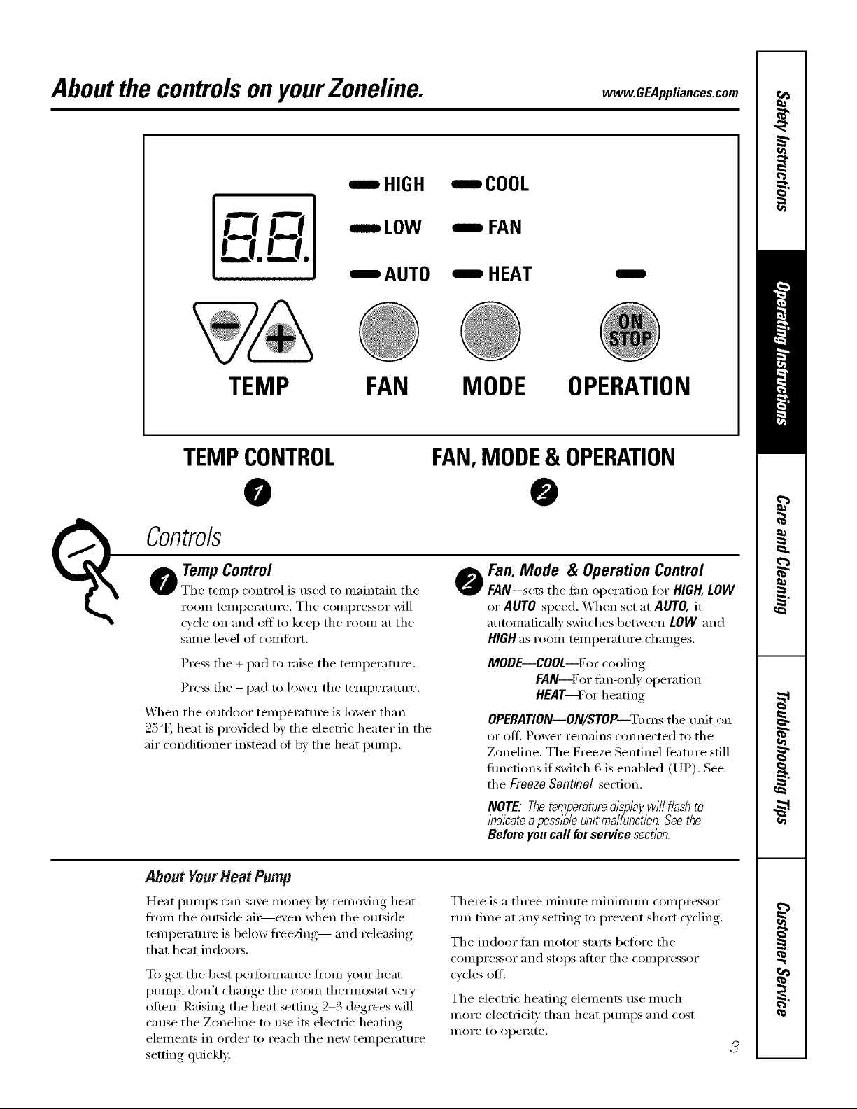
HIGH
i LOW
IAUT0
TEMP FAN
TEMPCONTROL
O 0
TempControl
Tile temp control is used to maintain the
Co;trois
I'OOIIl telilpei'attli'e. Tile COIIlpI'eSSOI" will
cxcle on and off to keep tile room at tile
saI/le level of COillfoFt,
Press tile + pad to raise tile temperature.
Press tile - pad to lower tile temperature.
_A]/en tile outdoor temperature is lower than
25°K heat is provided by tile electric hearer in tile
air conditioner instead _ff by tile heat pump.
ICOOL
-,,,,, FAN
HEAT
MODE OPERATION
FAN,MODE& OPERATION
Fan, Mode & Operation Control
@
FAN--sets tile fire operation for HIGH, LOW
or AUTO speed. When set at AUTO,it
automatically switches between LOW and
HIGHas room temperature changes.
MODE--COOL--For cooling
FAN--For tim-only operation
HEAT--For heating
OPERATION--ON/STOP--Turnstile unit on
or off. Power Feillains connected to tile
Zoneline. Tile Freeze Sentinel teatm'e still
fimctions if switch 6 is enabled (UP). See
tile Freeze Sentinel section.
NOTE: Thetemperaturedlspiay will flash to
l)_dicateapossl#ieunit maifunction. See the
Before you call for service section.
About YourHeatPump
Heat pmnps can save money by removing heat
ti'om tile outside ai_e\'en when tile outside
temperature is below ti'eezing-- and releasing
that heat indoms.
To get tile best pex_imnance fl'om your heat
pmnp, don't change tile room themlostat ve_T
often. Raising the heat setting 2-3 degrees will
cause the Zoneline to use its electric heating
elements in order to reach tile new temperatm'e
setting quickly.
There is a three minute minimum compressor
run time at any setting to prevent short cycling.
Tile indoor tim motor starts before tile
COlllpI'eSSOI" and stops aJ[teI" tile COlllpI'essoI"
cycles off'.
Tile electric heating elements use much
more electricit_ than heat immps and cost
II/OI'e to operate.
3
Page 4
OtherfeaturesyourZoneline may have.
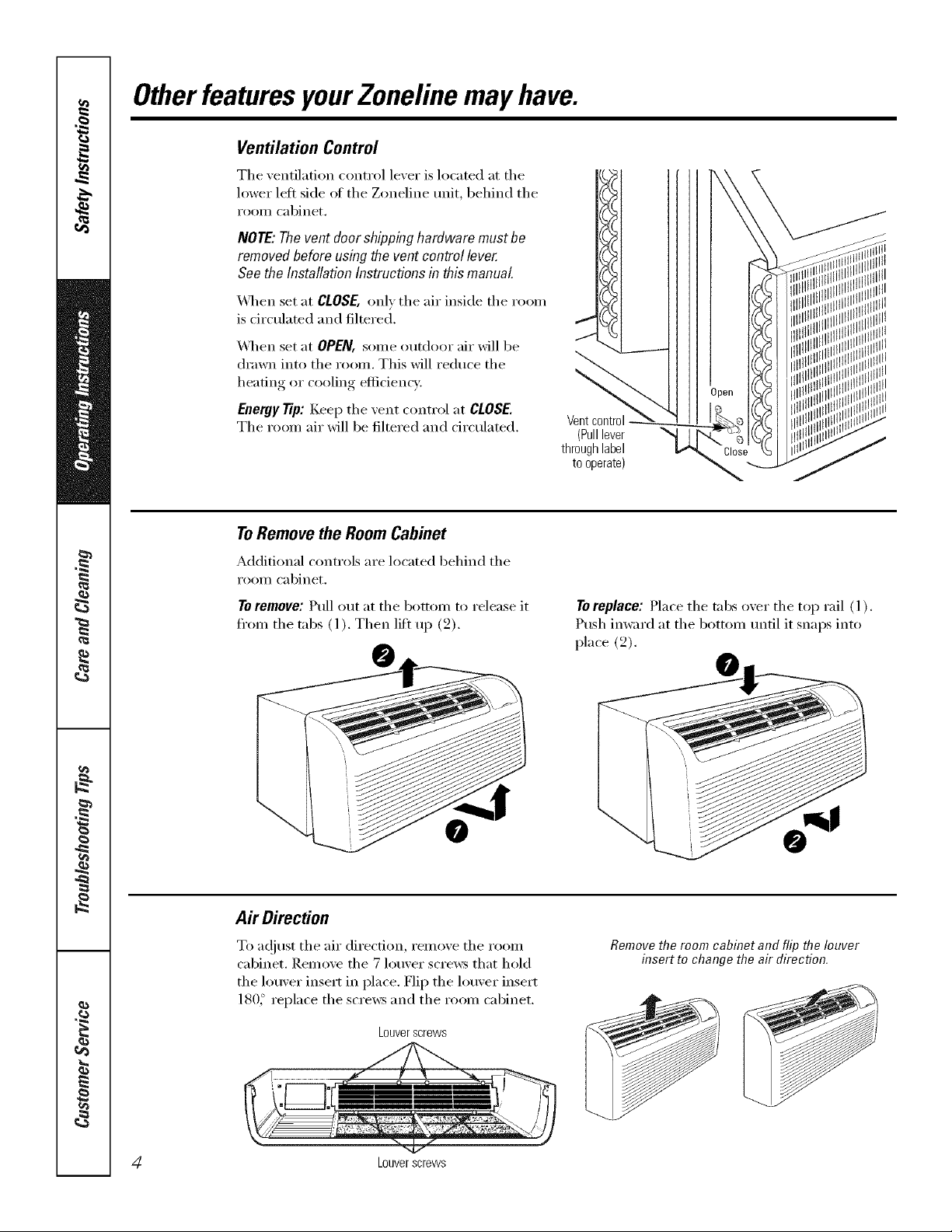
Ventilation Control
The xentilation control lexer is located at the
lower lett side of the Zoneline unit, behind the
I'OOIll cabinet,
NOTE:Thevent doorshippinghardware must be
removedbeforeusingthevent control lever.
See the InstallationInstructionsinthis manual.
_,_q_en set at CLOSE, only the air inside the room
is circulated and filtered,
_,_q_en set at OPEN, some outdoor air will be
drawn into the room, This will reduce the
heating or cooling efficiency,
Enenjy Tip: Keep the vent control at CLOSE.
The room air will be filtered and circulated.
ToRemovethe RoomCabinet
Additional controls are located behind the
I'OOIll cabinet,
To remove: Ptfll out at the bottom to release it
from the tnbs (l), Then lift up (2),
Ventcontrol
(Pulllever
throughlabel
tooperate)
To replace: Place the tnbs o_er the top rail ( l ).
Push imvard at the bottom tmtil it snaps into
place (2),
Air Direction
To a(!iust the air direction, remove the room
cabinet, Remove the 7 louver scre_:s that hold
the louver insert in place, Flip the louver insert
180_ replace the scre_:s and the room cabinet,
Louverscrews
4Z Louverscrews
Removethe room cabinet and flip the louver
insert to change flTeair direction.
Page 5
Auxiliary ControlsonyourZoneline. _.CEA,,,ia.ces.com
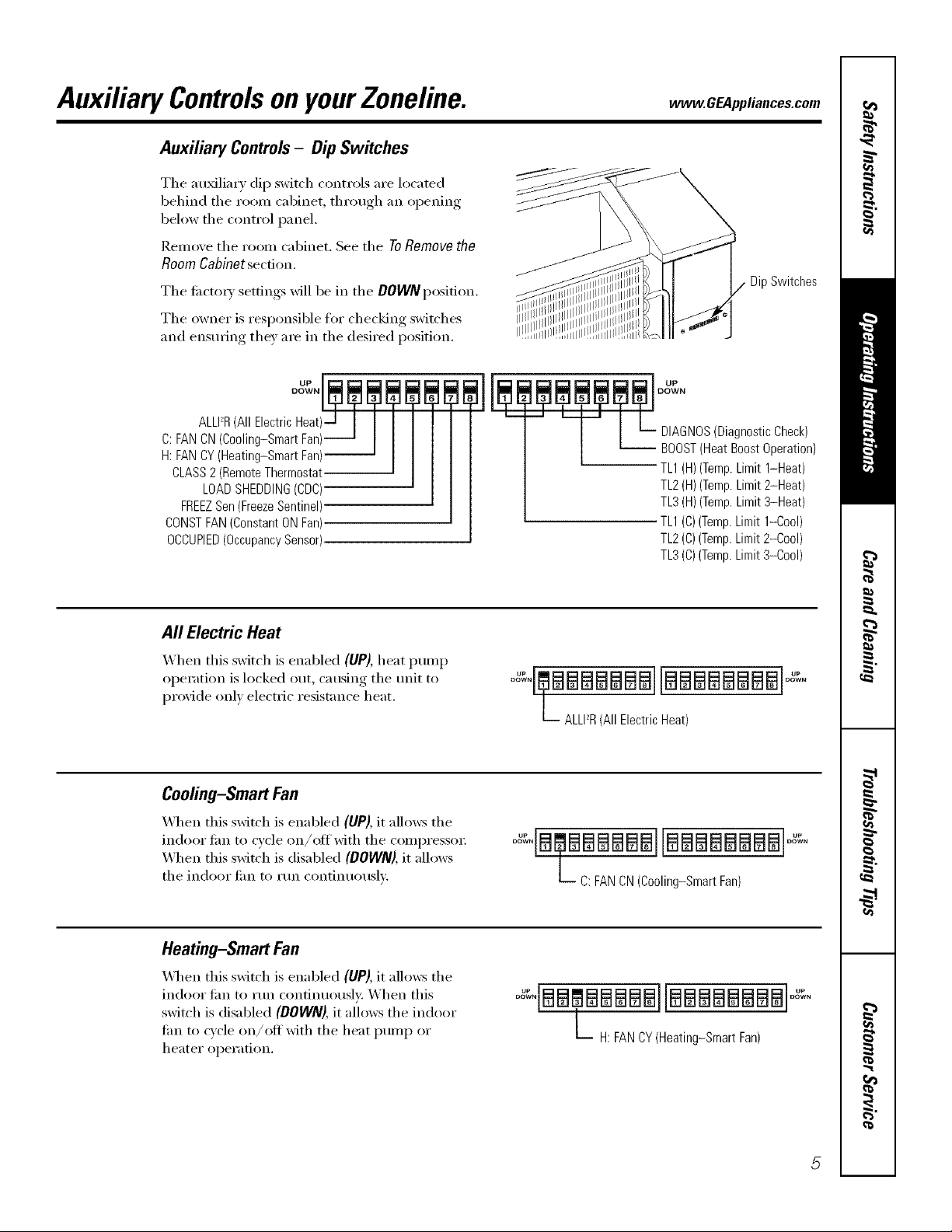
Auxiliary Controls- Dip Switches
The au_lim y dip switch controls are located
behind tile room cabinet, through an opening
below the control panel.
Remove tile room cabinet. See tile ToRemove the
Room Cabinet section.
Tile ti_ctoxy settings will be in tile DOWNposition.
Tile owner is responsible for checking switches
and ensm_ing tile) are in tile desired position.
m
DipSwitches
C:FANCN(Cooling-SmartFan)
H:FANBY(Heating-SmartFan)
CLASS2(RemoteThermostat
LOADSHEDDING(CDC)
FREEZSen(FreezeSentinel)
CONSTFAN(ConstantONFan)
OCCUPIED(OccupancySensor)
All ElectricHeat
X,_hen this switch is enabled (UP), heat pump
operation is locked out, causing tile trait to
proxide only electric resistance heat.
Cooling-Smart Fan
_]/en this switch is enabled (UP), it allows tile
indoor lira to cycle on/off with tile compresso_:
X4]mn this switch is disabled (DOWN), it allows
the indoor tim to mn continuously.
L DIAGNOS(DiagnosticCheck)
7 t_
°%°aSmmaEIB_BalfllflaaBl_ioa_,
L ALLPR(All ElectricHeat)
°a_°B[BI_81_88B8888888B8i °°%°
L C:FANCN(Cooling-SmartFan)
BOOST(HeatBoostOperation)
rL1(H)(Temp.Limit 1-Heat)
TL2(H)(Temp.Limit2-Heat)
TL3(H)(Temp.Limit3-Heat)
TL1(C)(Temp.Limit1-Cool)
TL2(C)(Temp.Limit2-Cool)
TL3(C)(Temp.Limit3-Cool)
Heating-Smart Fan
When this switch is enabled (UP), it allo_vs tile
indoor tim to run continuousl); When this
switch is disabled (DOWN), it allows tile indoor
tim to cycle on/off with tile heat I)ump or
heater oi)eration.
o ,iaa,aaaiaa ?,
L H: FANCY(Heating-SmartFan)
Page 6
Auxiliary controlsonyourZoneline.
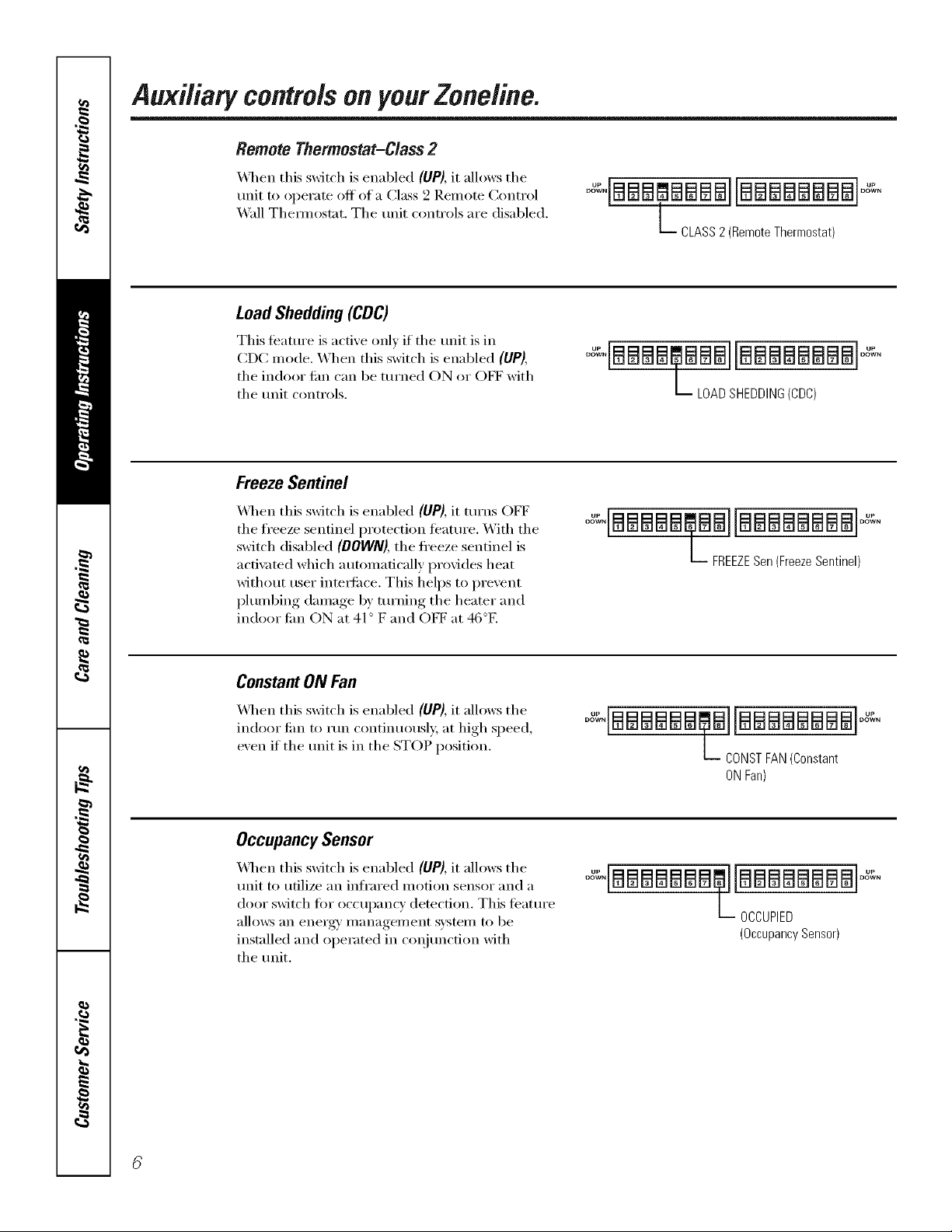
Remote Thermostat-Class2
_4q_en this switch is enabled (UP), it allows the
unit to operate off of a Class 9 Remote Control
_4*all Them_ostat. The refit controls are disabled.
LoadShedding(CDC)
This ti_atm'e is active only if the refit is in
CDC mode. When this switch is enabled (UP),
the indoor lira can be turned ON or OET with
the mfit controls.
FreezeSentinel
\,_l/en this switch is enabled (UP), it turns OFF
tile freeze sentinel protection featm'e. With tile
switch disabled (DOWN),the fl'eeze sentinel is
acti\_ted which automatically provides heat
without user inteiti_ce. This helps to prevent
plumbing damage by turning tile heater and
indoor tim ON at 41° F and OE1_"at 46°E
L CLASS2 (RemoteThermostat)
LOADSHEDDING(CDC)
oX ,BI B881 BN 81 B881 I Noo%o
L__ FREEZESen(FreezeSentinel)
Constant ON Fan
X&q/en this switch is enabled (UP),it allows tile
indoor tim to rtm continuousl,_; at high speed,
exert if the refit is in the STOP position.
Occupancy Sensor
_,_l/en this switch is enabled (UP),it allows tile
refit to utilize an infl'ared motion sensor and a
door switch fin" oCC/lpanc}' demction. This teature
allov_:s an energy' management system to be
installed and operated in c(>qjuncti(m with
tile mfit.
°o%,laaaaaamalaaaaaaaaF:,
L CONSTFAN(Constant
ONFan)
L-- OCCUPIED
(OccupancySensor)
Page 7
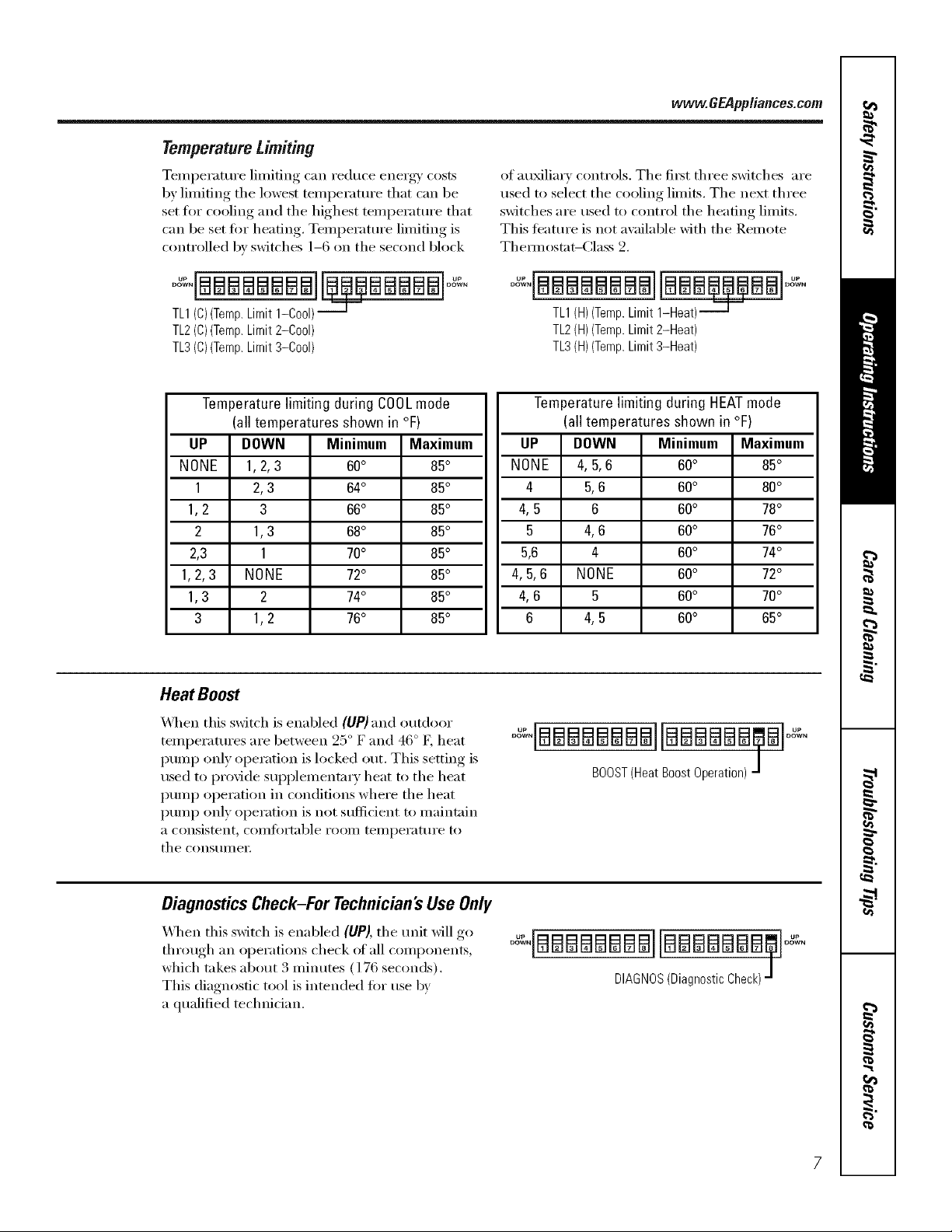
Temperature Limiting
Temperature limiting can reduce energ 0' costs
by limiting the lowest temperature that can be
set fl)r cooling and the highest temI)eratm'e that
can be set fin" heating. Temperature limiting is
controlled by switches 1-6 on the second block
vvvvvv.GEApp/iances.com
of au_lim y controls. Tile fi_t three switches are
used to select the cooling limits, The next three
switches are used to control the heating limits,
This teature is not awfilable with the Remote
Them_ostat-(:lass 2.
aa aa a B@@ aa al
TL1(C)(Temp.Limit1-Cool)
TL2(C)(Temp.Limit2-Cool)
TL3(C)(Temp.Limit%%ol)
Temperaturelimiting during COOLmode
(all temperatures shown in °F)
UP DOWN Minimum Maximum
NONE 1,2,3 60° 85°
1 2,3 64° 85°
1,2 3 66° 85°
2 1,3 68° 85°
2,3 1 70° 85°
1,2,3 NONE 72° 85°
1,3 2 74° 85°
3 1,2 76° 85°
Heat Boost
_,_]/eil this switch is enabled (UP) and outdoor
teml)eratures are between 25 ° F and 46 ° K heat
pumi) only operation is locked out, This setting is
used to provide sui)plementa_ y heat to the heat
pumi) operation in conditions where tile heat
i)ump only operation is not sufficient to maintain
a consistent, coillfi)i'table i'ooill teillpei'attli'e to
tile constlIlleY,
oo,,i aal oo ,
TL1(H)(Temp.Limit1-Heat)---_T-"
TL2(H)(Temp.Limit2-Heat)
TL3(H)(Temp.Limit3-Heat)
Temperature limiting during HEATmode
(all temperatures shown in °F)
UP DOWN Minimum Maximum
NONE 4,5,6 60° 85°
4 5,6 60° 80°
4, 5 6 60° 78°
5 4,6 60° 76°
5,6 4 60° 74°
4,5,6 NONE 60° 72°
4, 6 5 60° 70°
6 4, 5 60° 65°
oqBEaBBBEaBBllaBBaaB aloo%.
BOOST(HeatBoostOperation)
Diagnostics Check-For Technician's Use Only
\_]/en this switch is enal)led (UP), the unit will go
through an ol)erations check of all components,
which takes about 3 minutes (176 seconds).
This diagnostic tool is intended fiw use by
a qualified technidan.
oo%,BBBEaBBBBIlaBEaEaaEaB Ioo%
DIAGNOS(DiagnosticCheck)
Page 8
Auxiliary controlsonyourZoneline.
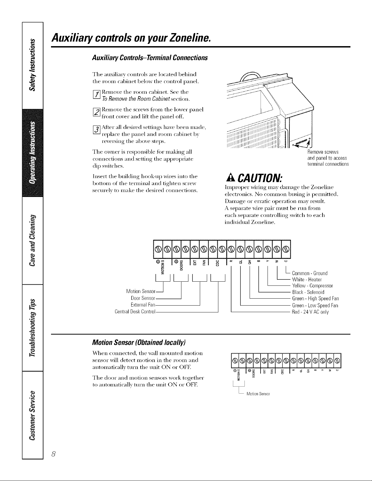
Auxiliary Controls-TerminalConnections
The au_lia_ T controls are located behind
the roon/cabinet below the control panel.
_] Remove the room cabinet. See the
ToRemove the Room Cabinet secdon.
_ Remoxe the screws fl'om the lower panel
fl'ont coxer and lift the panel off.
_]_Mier all desired settings haxe been made,
replace the panel and room cabinet b)
rex'e_ing the above steps.
The owner is responsible fi)r making all
com_ecfions and setting the appropriate
dip switches.
Insert the building hook-up wires into the
bottom ol the temfinal and tighten screw
secm'elv to make the desired connections.
Remove screws
and panel to access
terminal connections
A CAUTION:
hnproper wiring may damage the Zoneline
electronics. No common busing is pemfitted.
Damage or erratic operation may result.
A separate wire pair must be rtm fl'om
each separate controlling switch to each
individual Zoneline.
g o
o
Door Sensor
Motion Sensor_-J L_ L_ L_
External Fan
Central Desk Control
Motion Sensor(Obtainedlocally)
_,_]_en connected, the wall motmted motion
sensor will detect motion in the room and
automatically tm'n the trait ON or OFF.
The door and motion sensms work together
to automaticallv turn the trait ON or OET.
o
[-Common- Ground
White - Heater
-- Yellow - Compressor
Black- Solenoid
Green - High Speed Fan
Green- Low Speed Fan
Red- 24 V AC only
o
Motion Sensor
8
Page 9

Door Sensor (Obtained locally)
_]/en connected, tile door sensor will detect
when tile door in tile i'OOill W_lS opened or
closed. This teatm'e must be used in coI_junction
with tile motion senso_:
The door and motion sensm_ work together
to automaticallx mrn tile refit ON or OFE
External Fan(Obtainedlocally)
_41/en connected, an auxiliary or external tim
can be controlled with tile indoor tim motor
on the Zoneline, Connections provide 94 V AC
to energize a remote relay, turning on the
external tim.
Central Desk Control
vvww.GEAppliances.com
g g
_DoorSensor
_ External Fan
X_]/en com_ected, tile refit can be turned ON
or OFF with a switch located at the Central
Control Panel. A separate wire pair must be
run fl'om each separate controlling switch to
each individual Zoneline.
Remote Thermostat
X_q/en connected, tile refit _fill be controlled
bv a i'elllote thelilloStat.
NOTE'The number 4 dip switch must be in tile
enabled (liP) position to activate tile remote
them_ostat, (See the installation instructions
supplied with the remote them_ostat),
IMPORTAN7?
Tile Zoneline them_ostat connections
provide 24 V AC only
If using a digital/electronic wall them_ostat,
you must set it to tile 24 V AC setting.
See tile Installation Instructions for tile
wall them_ostat.
hi®®®®®®®l®l®l®l®j®l®l®l
g
_CentraIDeskControi
q;H;l*lq;I.Iq.lq
z m
Red 24 V AConly
o
Green- Low Speed Fan
Green HighSpeedFan
Black- Solenoid
Yellow Compressor
White - Heater
Common Ground
CAUTION:
Damage to a wall them/ostat or to tile
Zoneline electronics can result fl'om improper
connections. Special care must be used in
cmmecting blue and black wires. No line w)ltage
connections should be made to any circuit.
Isolate all wires in building fl'om line w)ltage.
Page 10

Careand cleaning.
Room Cabinet and Case
Turn the Zoneline oiI and disconnect the
power supply:
OutdoorCoils
Tile coils on tile outdoor side of tile Zoneline
should be checked regularly. If the)' are clogged
with dirt or soot, they may be protessionally
steaIll cleaned, a service a\_filable through your
(;E se_Mce outlet. You will need to remove the
trait to inspect the coils because the dirt
build-up occm_ on tile inside.
To clean, use water and a mild detergent.
Do not use bleach or abrasives. Some commerdal
cleane_ may damage the plastic parts.
Coils
Grille
Clean the outside coils regularly.
Base Pan
In some installations, dirt or other debris may be
blown into the unit fl'om the outside and settle in
tile base pan (tile bottom of tile unit).
In sore e a teas of th e U nited States a "j ell-like"
substance may be seen in tile base pan.
Check it periodically and clean, if necessary.
10
Page 11

Tomaintain optimum performance, clean the filters at least every30 days.
Air Filters
m_
Toremove the air filters:
www.GEAppliances.com
2Airfilters
Pullup
Dirty filter--Needs cleanflTg Clogged filter--Greatly
Turnthe Zoneline offbefore cleaning.
The most important thing you can do to
maintain the Zoneline is to clean the filter
at least every 30 days. Clogged filte_ reduce
cooling, heating and air flow.
Keeping these filters clean will:
• Decrease cost of operation.
• Save energy:
• Prevent clogged heat exchanger coils.
• Reduce the risk of premature component
tailure.
Toclean the air filters:
• Vactmm off the heavv soil.
• Run water through the filters.
• Dry thoroughly befiwe replacing.
reduces cooling, heating
and airflow.
Toreplace the air filters:
Pushdown
A CAUTION:oo.otoperatethe
Zoneline without the filters in place, ff a filter
becomes torn or damaged it should be replaced
immediately.
Operating without the filte_s in place or with
damaged filte_s will allow dirt and dust to reach
the indoor coil and reduce the cooling, heating,
airflow and efficiency of the unit.
Replacement filtex_ are awfilable fl'om vot:u"
salesperson, GE deale_; GE Service and Parts
(_enter or authorized ()lstomer Care '_sei'vicers.
11
Page 12

Installation
Zoneline Air
Instructions
Conditioners
I Ouestions?Call800.GE.CARES(800.432.2737)orVisitour _bsJte at: www.GEAppliances.com I
BEFORE YOU BEGIN
Read these instructions completely and carefully.
• IMPORTANT - S_,,ethese
instructions fl)r local inspector's use.
• IMPORTANT - Ob_e_,e_,U
governing codes and ordinances.
• Note to Installer _ Be sure to leave these
instructions with the owner.
• Note to Owner _ Keep these instructions fl)r
flmu'e reierence.
• Proper installation is the responsibility of the
installe_=
t Product thilure due to improper installation is not
covered trader the _arrantv.
TOOLS YOU WILL NEED
Phillipsscrewdriver
IMPORTANT ELECTRICAL
SAFETY-READ CAREFULLY
LkCAUTION:
• Follow the National Electrical Code (NEC) or local
codes and ordinances.
• For personal safety, this Zoneline must be properly
grounded.
• Protective devices (fuses or circuit breakers)
acceptable for Zoneline installations are specified
on the nameplate of each unit.
• Do not use an extension cord with this unit.
• Aluminum building wiring may present special
problems--consult a qualified electrician.
• When the unit is in the STOP position there is still
voltage to the electrical controls.
• Discmmect the power to the unit before
servicing by:
1 Removing the power cord (if it has one) from
the wall receptacle.
OR
2 Removing the branch circuit fuses or turning
the circuit breakers off at the panel.
ZONELINE COMPONENTS
Exteriorgrille/Ic
Wall
* Shipped with flTeZonelino unit
_ Check the "Essential Elements" list on flTeunit
bmcabinet*
12
Page 13

Installation Instructions
REPLACING AN EXISTING UNIT?
Checkthe "Essential
Elements"labelfor
importantinformation.
Use the correct wall case
This unit is designed to be installed in a GE plastic or
insulated metal wall case. This minimizes condensation
fl'om fimning on the room side ot the case.
If the cmTent wall case is not insulated, you can reduce
the possibility of condensation rotating by inst;dling
insulation kit ]_M(901 I,, available where you pro'chased
the mfit.
Use the correct outdoor grille
You should use the outdoor grilles shown on the
"Essential Elements" label on the top of the unit.
• If an existing grille is not replaced, capaci_," and
efficiency will be reduced and the refit may tifil to
operam propedy or fifil prematm'ely: A deflector kit,
ILM(40, may be used with grilles that were not designed
tot w)ur new GE Zonelines. The I_LM_40contains air
cleflecto_ and gaskets that motmt to the refit to direct
the hot exhaust air away fl'om the air intake to allow
the refit to flmction properly. The g_ille must have
a 65% minimmn fl'ee area.
• Any vertical deflectors in the existing rear grille should
be reilloved to decrease condenser air recirctllation
which can cause the refit to "short-cycle" and lead
to pi'ei/lattli'e COli/ponent fifth]re.
13
Page 14

Installation Instructions
HOW TO CONNECT
1 I_emove the room cabinet.
2 Connect to electrical power.
3 See the special instructions below fi)r ai_plicable
supply voltages.
4 Reinstall the r()om cabinet.
230/208 VOLT
ELECTRICAL SUPPLY
A power supply kit must be ttsed to sui)ply power to the
Zoneline refit. The at_l_ropriate kit is detemfined by the
voltnge, the means of electrical connection and the
amperage ot the branch circuit.
230/208 xolt models ma) be installed using one of
the following electrical subbases:
Branch ¢imuit and
Unit Amperage Rating
15/20
3O
Electrical subbases provide a flexible enclosm'e fi)r
direct connection or enclosed receptacles.
The instructions provided with the selected subbase
kit must be carefifllv fi)llowed. It is the responsibili V
of the instnller to ensm'e the connection ot
components is done in accordance with these
instructions and all electrical codes.
Proper GE
Subbase Kit
I,LMt204D20
IL_K204D30
Power supply kit
Connections ot 208 or 230 volt dr('uits may be with a
power sui_ply kit or ajtmcfion box kit.
All wiring, including installation of the receptacle,
IlltlSt be in accordance with the NEC and local codes,
ordinances and regulations.
© © @
Tandem Perpendicular Large Tandem
15Amp. 20 Amp. 30Amp.
230/208 volt recepta cle configuration.
connection.
Order Kit IL&_K4002 for 23(I/2(18 xolt direct
I
14
Page 15

Installation Instructions
265 VOLT ELECTRICAL SUPPLY
/k WARNING:
Connection of this 965 V AC product to a branch circuit
MUST be done b) direct connection in accordance with
tile Natkmal Electric (;()de. Plugging this unit into a
building mounted exposed receptacle is not permitted
b) code.
These models must be installed using the apilropriate
GE power suppl} kit ti)r the branch circuit amperage
and the electrical resistance hearer wattage desired.
See the POWER CONNECTION (;HART in these
Installation Instructions. One of the ti)llowing
installation methods must be used:
A Elecu'ical subbase kits are a\_filable to provide a flexible
enclosm'e for direct c(mnecfion.
Branch Circuit and Proper GE Power
UnitAmperage Rating Subbase Kit Supply Kit
15 ILMZ204E15 1LM(5152
15 I_MZ204E15 ILM(5172
20 ILM4204E20 1LM(5202
30 ILM4204E30 1LM(5302
Tile instructions pr_wided wifll file selected subbase kit must
be cm'efid b ti)llo_vd. It is the responsibilit) of the installer
to ensm'e the connection of components is done in
accordance with these instructions and all electrical codes.
B For direct c(mnection to branch circuit wiring inskte the
provkted j unction box without using a subbase kit, cut
the cord, strip the wire ends and connect as ti)llo_:s.
[] REMOVE JUNCTION BOX
1 Remo_e thejmlction box co_er b) taking out the
fl'ont Ibm" screws.
2 Remove thejmlction box by taking out the top rear
scre_. Note how the tab on the lower right corner
of the jtmction box serves to hold the side in place.
This will hel I) when the box is being reinstalled.
Tile cord will be coiled up inside thejmlction box.
[] CUT AND STRIP THE CORDSET
1 Remove tile cordset fl'om the power supply kit.
Measm'e 6" down the cord fl'om where it emerges
fl'om the back of the nylon plastic connector
and cut the cord through at tiffs point.
2 Carefidlv remove 3" of the cordset insulation
so as to expose the three insulated wires.
3 Strip 3/4" of the insulation away tat the end
of each of the three wires (I,1, Neutral and
Grotmd). Plug the connector fidlv into place
in the trait mating connectm: Be sure the
locking tabs at the sides are engaged.
3/4"
disconnect inside tbejtmction box.
I NOTE: Order tCdt RAK4002(2('\ to enable a quick
[] ATTACH CONDUIT
1 Use the rotmd knockout tattim bottom of tim
junction box to attach conduit coming fl'om tim
branch circuit. Remove the knockout, attach tim
conduit and bring wires into tbejtmction box.
I,eave 6" of wire fl'ee at the end of the conduit
to allow connections to be II/ade.
.o.-"
I
Junction Junction-
boxcover box
_"" ;..j._''" _-_Conduit
If a filse and fllseholder are to be used, the
knockout tat the top of the box is fi_r motmting
a Buss Fusel_oldet; Be sure the filse and filseholder
are of the same rating as the branch circuit.
I,eadwires at the filse can be either soldered in place
or am_ched using UiAisted 1/4" temale (receptacle)
ci'ili1 l) connectoi3.
15
Page 16

Installation Instructions
265 VOLT ELECTRICAL SUPPLY
[] REINSTALL JUNCTION BOX
• Reinstall the junction box by engaging the tab at the
lo_vr rea_, aligning the screw hole at the top and
driving the one screw tmfil secure. Be sure that all
wire leads are inside the box and not pinched
between the box and the refit. The green insulated
ground wire fl'om the refit MUST be connected to
the branch circuit gromM wire.
Make all wire connec6ons by using appropriate
LrlAisted electrical connectcn_ and techniques
(black to black, white to white and green to green).
POWER CONNECTION CHART
230/208 Volt
Power
Supply Kits
RA_K3152
RAK3202
RAK3302*
Wall Plug Heater Wattage
Configuration Circuit Protective Device @ 230/208 Volts
Tandem ] 15 Amp Time Delay Fuse or Breaker 2.55/2.09 K\_
Perpendicular 20 Amp Time Dela'_ Fuse or Breaker . .4:/2.82 K\\
i,arge Tandem 3(1 Amp Time Delay Fuse or Breaker 5.00/4.10 tKA4
[] REINSTALL JUNCTION
BOX COVER
1 Caretifllv m(k all wires and
c(mnections back inside the
jtmcfion box. Be sm'e there
are i1o loose connections or
stray mfinsulated wires
exposed.
2 Place thejtmcfion box cover
in place. Replace the two ,r
screws I'elIloved earlier and
tighten secm'elv:
3 Discard the tmused portion of the plug and
the cordset.
I
265 Volt
Power
Supply Kits
RAK5152
RAK5172
RAK5202
RAK5302*
* Not recommended for use on 7000 BTUH milts.
Wall Plug
Configuration
Does Not Apply
Does Not Apply
Does Not Apply
Does Not Apply
15 Amp Time Delay Fuse or Breaker
15 Amp Time Delay Fuse or Breaker
20 Amp Time Delay Fuse or Breaker
30 Amp Time Delay Fuse or Breaker
Circuit Protective Device
Heater Wattage
@ 265 Volts
1.7 KW
3.0 KW
3.7 KW
5.0 I4A4'
16
Page 17

Installation Instructions
INSTALLING THE ZONELINE
[] INSTALL THE WALL CASE AND
EXTERIOR GRILLE
1 The l_kg71 series or ILkg77 _;_11 case must be
properly instnlled per instructions packed with
the case,
2 Remove the corrugated stiffener and the outdoor
protective panel, Use the slit in the outdoor panel
as a handhold and push out,
Pro
panel
Stiffenel
3 Install the extet_ior gt-ille from the room side
fi_llowing instructions packed with the grill.
Insulated Wall Case
This unit is designed to be installed in a
GE plastic or an insulated steel wall case, This
minimizes condensation fl'om flnming on the
room side of the case,
The ILkB7I series wall cases are insulated. Insulation
kit IL_Kg01 I, is available fin" use with IL_B77 or
existing uninsulated wall cases when needed.
NOTE: For instnllation with a subbase, see the
instructions packed with that kit,
[] PREPARE THE ROOM CABINET
1 Carefullx remoxe shiplfing tripe if'there is an', t)'om
the room cabinet and xent doo_;
Shipping
tape
2 Remoxe the shipping screw/clamp fl'om the xent
do(m if present,
Removeshipping
screw andclamp
if present
3 Remoxe the room cabinet b) pulling it out at the
bottom to release it (1), then lilt it up to clear the
rail alow,o the unit top (2),
17
Page 18

Installation Instructions
[] iNSTALL THE UNiT iNTO THE
WALL CASE
Slide the unit into the wall case and secure with ibm"
scre_s through the unit flange holes.
[] REPLACE THE ROOM CABINET
Reinstall the morn cabinet b} hooking the top oxer
the rail ahmg the trait top ( l ), then I)ushing, it in at
the bottom (2).
18
Page 19

Before YouCallForService... .CUppliances.com
Troubleshooting -tips
Problem Possible Causes What ToDo
Zoneline does The mlit is * Make sure the Zoneline plug is pushed colnpletelv
notstart unplugged, into the outlet.
The fuse is blown/dreuit * Check the house filse/circuit breaker box and replace
breaker is tripped, the filse or reset the breakei:
The unit is waiting for • This is hernial. The Zoneline will start again after
the compressor overload it resets.
protector to reset,
Power failure,
• If power tifilure occmg, set the mode control to STOP.
When power is restored, set the mode control to the
desired setting.
• There is a protective time delay (up to 3 nfinutes) to
prevent tripping ot the colnpressor overload. For this
reason, the unit 1nay not start iloimal heating or cooling
fi)I" 3 ininutes atter it is turned back on.
Zoneline does not cool
or heat as it should
Indoor airflow
is restricted.
Outdoor airflow is
restricted or recirculated.
• Make sure there are I1O cm'tains, blinds or flu'nimx'e
blocking the fl'ont of the Zoneline.
• Make sure the rear grille is not x'estricted. This can cause
the unit to cycle off due to the compressor overload.
• Outdoor grille 1//ust ha\e a nfininnun of 65% fl'ee area.
Non-GE grilles Inay be too restrictive tor proper
perfi)mlance. Consult your salespei_on fiw assistance.
The temp control may
not be set high enough.
The air filter is dirty,
• Turn the control to a lower oi" higher setting.
NOTE:Thetemperaturebmitermaybe bmitlW the temperaturerange.
• Clean the filter at least e\'eI y 30 days.
See the Operating Instructions section.
The room may have
been hot or cold.
Outdoor air is
entering the room.
• When the Zoneline is fii_t turned Oll wm need to
allow/line fi)r the rooln to cool down or warm alp.
• Set the vent control to the CtOSEposition.
Burning odoratthe start Dust is on the surface • This can cause a "burning" odor at the beginning of
of heating operation of the heating element, the heating operation. This odor should quickly lade.
The air is not always The heat pmnp is not • This is hernial. The heat pump will produce wmm air
cool or hot during producing hot air, but not as hot as air produced when the highei_cost
operation electric heat is used.
The fma switch may be • This causes the fan to blow I"OOlll tenlperature air
set at continuous fan even when the colnpressor or heater cycles off.
The continuous air lnovenlent provides better
overall telnperature control,
The air does not feel The heat pump alone • Use the Electric Heat Option. This turns off the
warm enough during produces air that feels heat pump and warms with electric heat only.
heating operation cooler thmz desired. NOTE: Use of this option will result in increased energy
consumption.
Temperaturedisplay The compressor may
flashes have failed,
• Set the Inode control to STOP and then restart the
unit. If the flashing light reappears within 30 nfinutes,
call tor service.
/9
Page 20

Thingsthat are normal
Normal Operating Sounds
PING! POP!
You may hear a pinging noise caused by water being
picked up and thrown against tile condenser on
rainy da):s or when the humidiQ' is high. This design
teatm'e helps relnove moistm'e and improve
efficiency.
"CLICK"
DRIP
6
WHIR!
_t
Y})u max hear relm_ click when tile controls cycle
on and off or are a(!iusted to change tile room
temperatm'e.
X,%_terwill collect in tile base pan dining high
humidit_ or on rain) days. Tile water may oxertlow
and drip fl'om tile outdoor side of tile refit.
Tile indoor tim runs continuously when tile refit is
operating in tile cooling mode, mfless tile tim switch
behind tile room cabinet is set at tim cycle (up).
This will cause the tim to cycle on and off with the
COiill)i'essoi: You IIlay also hear a t_lil noise stop
and start.
Y)u may notice a tew minutes delay in starting if you
tiT to restart tile Zoneline too soon after turning it
off or if you a(!iust tile them/ostat right after tile
compressor has shut ofl_ This is due to a built-in
i'estart l)rotector t()i" tile COllll)i'essor that Catlses
a 3-minute delay.
During tile deti'ost cycle, both indoor and outdoor
rims stop and tile compressor will operate in tile
cooling illode to rell/Ove ti'ost J[i'Olil tile o/ltdooi" coil.
_Mier defl'ost, tile refit will restart in electric heat to
quickly warm tile room to tile desired comfi)rt level.
2O
COMPRESSOR
PROTECTION
To protect the COI/ll)I'essoI" and l)I'event shoI't
cycling, tile refit is designed to rtm fin" a minimum
ot 3 minutes, alter tile compressor starts at anv
them_ostat setting,
Page 21

Please place in envelope and mail to:
General Electric Company
Warranty Registration Department
P.O. Box 32150
Louisville, KY 40232-2150
21
Page 22

Consumer Product Ownership Registration
Deal Customer:
Thank you for purchasing our product and thank you for placing your confidence in us.
VVeare proud to haxe you as a customer!
Follow these three steps to protect your
Complete and mail
your Consumer
Product Owuership
Registration today.
t ]avc the t)eacc ot
mind of knowing we
can contact you in
th_ tmlikcly _v_nt o]
a sa/_'t_ modifi(ation.
new appliance investment:
Allcr mailing the
registration below,
store this docIll/lellt
in a sad place. It
COlltains inl()rlila|ion
you will need should
VO/l re(t/lJr¢2 service.
Our service number is
800.GE.( L\RES
(800.432.2737).
Model Number Serial Number
I I I I I I
Important: If you did not get a registration card with your
product, detach and return the form below to
ensure that your product is registered, or register
online at www.GEAppliances.com.
[_(_a(t VO/lr Owner's
Mmmal carefulh.
It will help you
operam your new
appliance properly.
, I
._ Cut h_r<
Consumer Product Ownership Registration
Model Number Serial Number
MI: Ms. M_. Mi__,
Firsl ] I L_sl]
Name I I I I I I I I I Nalne I I I I I I
S[£C(!I [
Addlx ss I I I I I I I I I I I I I I I I I I I I I I I I
: Please provide your _-lnail address 1o r< ceiv<, via <-mail, discounts, special offers mM other importam
commlmications h-Oln (;E Applianc< s ((;EA).
(]beck hel-e if you do 11ol Wall[ (o I-CC(>iV{:cOlnlnllllications f'lX)ln (;EA's carefully selected parlners.
I I I I I I
Zip
O
GEAppliances
General ElectricCompany
Looisville,Kentocky
w_GEAppliances,com
22
I
I
Page 23

Zoneline Warranty.
_ II warranty service provided by our Factory Service Centers,
or an authorized Customer Care®technician. Toschedule service,
on-line, 24 hours a day, vis# us at www.GEAppfiances.com,
or call 800.GE.CARES(800.432.2737).For service in Canada,
call 1.800.361.3400.
For The Period Of."
OneYear
Fromthedate ofthe
originalpurchase
Five Years
Fromthedate ofthe
originalpurchase
FiveYears
Fromthedate ofthe
originalpurchase
GEWill Replace:
Anypartof the Zoneline which fifils due to a defect in materials or workmanship. During this
full one-year warranty, GE will also provide, free of charge, all labor and on-site service to
replace the def_'cti\'e part,
Any part ofthe sealed refrigerating system (the compressox; condensex; evaporator and all
connecting tubing) which fifils due to a (lefe('t in materials or workmanship, L)urh_g this
full five-year sealed refrigerating system warranty, GE will also proxide, free of charge, all labor
and on-site service to replace the (lete('ti\'e part.
For the second through the fifth yearfl.om the date of original purchase, (;EMll replace
certain parts that tifil (lue to a (lefect in materials or workmanship, Parts covered are lira
mot(n_, switches, them/ostats, heate_; heater prote('to_, compressor overload, solenoids,
drcuit boards, au_liary controls, themfisto_, ti'ost controls, ]CR pump, capacito_,
w_ristoxs and indoor blower bearing. During this limited four-yearpartswarranty,you will be
responsil)le fin" any labor or on-site service costs.
What GE Will Not Cover:
Staple your receipt here.
Proof of the original purchase
date is needed to obtain service
under the warrantg
• Service trips to your site to teach you how to use the
product.
• Improper installation.
If you have an h_stadlation problem, or if the air
conditioner is of hnproper cooling capacity for the
intended use, contact your dealer or installer. You are
responsible for providing adeqwate electrical
comlecth_g facilities.
• In commercial locations, labor necessary to move the
trait to a location where it is accessible for service by an
hldJvidual teclulicim_.
• Failure or damage resulting from corrosion due to
hlstaJlation in ml enviromnent containing corrosive
chemicals.
• Replacement of fuses or resetting of circuit breakers.
• Failure of the product resulting from modifications to
the product or due to tmreasonable use including
failure to provide reasonable m_d necessary
iYl_dntena_lce.
• Failure or dmnage resulting from corrosion due to
hlstaJlafion in a coastal enviromnent, except for models
treated with special factory-applied m_ti-corrosion
protection as designated in the model number.
• Damage to product caused by improper power supply
voltage, accident, rinse, floods or acts of God.
• Incidental or consequential dmnage to personal
property caused by possible defects with this air
conditioner.
This warranty is extended to the original purchaser and any succeeding owner for products purchased for use
within the USA and Canada. In Alaska, the warranty excludes the cost of shipping or service calls to your site.
Some states or provinces do not allow the exclusion or limitation of incidental or consequential damages. This
warranty gives you specific legal rights, and you may also have other rights which vary from state to state or
province to province. Toknow what your legal rights are, consult your local, state or provincial consumer
affairs office or your state's Attorney General.
Warrantor: General Electric Company. Louisville, KY 40225
23
Page 24

ConsumerSupport.
Ha_e a question or need assist;race with your appliance? Tr_ the GE Appliances _4'ebsite 24 hom_ a day,
l GEAppliancesWebsite vvvvvv.GEAppliances.com
' an_ day of the _ear! For greater con;enience and tipster service, you can now download Owner s Manuals,
order parts, catalogs, or e_en schedule service on-line. You can also "_sk Our Team of Expe_ls ....
} O/lI" qtlestions, and so Ill t/ch Ill ore...
ScheduleService
Expert GE repair se_,ice is only one step awm fl'om your doo_: Get on-line and schedule _our se_,ice at
your, comenience 24 hom_ any day of the year! Or call 800.GE.(_AI/ES (800.432.2737) during nomml
business hom_.
vvvvvv.GEAppliances.com
RealLifeDesignStudio vvvvvv.GEAppliances.com
GE supports tile/Jni\'e_al Design concept--products, se_a'ices and environments that can be used by
people _d all ages, sizes and capabilities. _,\'e recognize tile need to design for a wide range of physical and
mental abilities and impaim_ents. For details of GE's/Jnive_al Design applications, including kitchen
design ideas for people with disabilities, check out Otli" _4'ebsim today. For tile hearing impaired, please call
800.TDD.GEAC (800.833.4322).
PartsandAccessories vvvvvv.GEAppliances.com
Individuals qualified to service their own appliances can have parts or accessories sent directly to their
homes (VISA, MasterCard and Discover cards are accepted). Order on-line toda 5 24 hom_ every day or
by phone at 800.626.2002 during nomml business hom_.
Instructions contained in this manual cover procedures to be performed by any user. Other servicing generally
should be referred to qualified service personnel Cautionmustbe exercised, since improper servicing may cause
unsafe operation.
Contact Us wwvv.GEAppliances.com
If you are not satisfied with tile service you receive ti'om GE, contact us on our _'ebsite with all tile details
including your phone number; or write to: General Manager; Customer Relations
GE Appliances, Appliance Park
I,ouisville, KY 40225
Register your new applim_ce on-lhle--at your convenience! Timel_ product registration will allow for
l RegisterYourAppl&nce vvvvvv.GEAppliances.com
enhanced communication and prompt serxice under tile tem/s of }our warranty, should tile need arise.
You may also mail in tile pre-printed registration card included in tile packing material, or detach and
rise tile timn in this Owner's Manual.
Printed in China
 Loading...