

Page 1
@
@
www.GEAppfiances.com
Sa]bty Instructions. .......... '2
Operating h_iructions
Aft Di _ectkm ................ 4
AuxiliaIw C(mtIols .......... 5-9
Con tIols .................... 3
To Remove the Room Cabi_et . .4
Ve_t C(mtrol ................ 4
Care and Cleaning
Air Filters .................. t 1
Base Pan .................. 1()
Outdo(n Coils .............. t0
Room Cabh_et a_d Case ...... 10
Ve_t Filter . ................ t0
Installation Instructions
Electrical Supply ......... t4-17
InstalliI_g the Zoneli_e .... 18, 19
Optional Drain Kit .......... 20
Preparation ................ 12
Replacii_g ai_ E×isti_g Ui_it? . . .t3
Troubleshooting Tips .... 21, 22
Noimal Operath_g Som_ds .... 23
Heat/Cool Model 2800
Heat Pum]a Model 3800
Espa_ol
For a Spanish version of this
manual, visit our _Yebsite at
w_vw.GEAppliances.com.
Para consultar una version ell
espafio] de este manual de
instrucciones, visite nuestro
sitio de internet
w_a,w.GEAppliances.com.
Fran_aise
For a French version of this
manual, visit our VCebsite at
w_a,w.GEAppliances.com.
Pour une version flanqaise de
ce manuel d'utilisation, veuillez
visiter notre site web fi ]'adresse
w,a,w.GEAppliances.com.
0
Consumer Support
Consumer Support . . .Back Co_er
Product RegistratioI_ ...... 25, 26
XA_na_ tv . ................. 27
Write the model and serial
numbers here:
Model #
Serial #
Find these numbers on a label
behind the room cabinet on the
base pan.
TINSEA361JBRZ 49-7511
07-05JR
Page 2
IMPORTANTSAFETYINFORMATION.
READALLINSTRUCTIONSBEFOREUSING.
WARNING!
Foryour safe_ the information in this manual must be followed to minimize the risk of fire or
explosion, electric shock, or to prevent property damage, personal injury, or loss of life.
SAFETYPRECAUTIONS
This Zoneline must be properly
installed in accordance with the
Installation Instructions before it is
used. See the Installation Instructions
in the back of this manual.
• Immediately repair or replace all
electric service cords that have become
flaved or otherwise damaged.
• Unplug or disconnect the Zoneline at
the fllse box or circuit breaker before
making any repairs.
NOTE;¼:e strongly recommend that any
servicing be performed by a qualified
individual.
Replacing an existing unit?
For details, see the Installation
Instructions in this manual.
READANDFOLLOWTHISSAFETYINFORMATIONCAREFULLY.
SAVETHESEINSTRUCTIONS
2
Page 3

Aboutthe controlsonyourZoneline. .CEA..lia.ces.com
?
TEMPCONTROL
0
TempControl
The temp control is used to maintain the
Co trols
I'00111 tell/pei'att/i'e. The COlll[)i'essoi" will
c_cle on and off to kee I) the room at the
same comtort level. _,_]_en w)u tm'n the
knob to COOLER(blue), the indoor air
will become cooler. Tm'n the knob to
WARMER (red) and the indoor air will
becollle wa illlei i
3800Series only
_,_]_en the outdoor temperatm'e is lower
than 20°E heat is provided b)' the electric
heater in the air conditioner instead of bv
the heat I)ump.
MODECONTROL
@
Mode Control
HIGH COOLand LOW COOLpr_Mde cooling
with different tim speeds.
HIGHHEATand tOW HE4Tprovide heating
with different tim speeds.
LOWFAN or HIGH FAN provides air
circulation and filtering without cooling
or heating.
NOTE:If youmove the switch from acool orheat
setting to STOPorto a fan setting, the unit hasan
automatic3-minute delaybefore a//owlbg the
compressortorestart in thecool or heatmode.
About YourHeat Pump (3800 Series only)
Heat pmnps can save money by removing heat
fl'om the outside air----even when the outside
temperature is below freezing--and releasing
that heat indom_.
To get the best pet_kmnance flxm_ ):ore" heat
l)ump, don't change the room them_ostat ve_y
otten. Raising the heat setting 2-3 degrees will
cause the Zoneline to use its electric heating
elements in order to reach the new temperatm'e
setting quickly.
There is a three mimlte minimum compressor
run time at any setting to prevent short cycling.
The indoor tim motor sta_*s befl)re the
COllll)I'essoI" and stops aJ[teI" the coI/ll)I'essoI"
cycles off.
The electric heating elements use much
more electricit_ than heat l)mnps and cost
II/OI'e to ol)erate.
3
Page 4

Otherfeaturesof yourZoneline.
Ventilation Control
The xentilation control lexer is located at the
upper lett side of the Zoneline unit, behind
the room cabinet.
_,_q_en set at the closed position, onE' the air
inside the room is circulated and filtered.
X,_]_en set at the open position, some outdoor
air will be drawn into the room. This will
reduce the heating or cooling efficiency.
Energy Tip: Kee I) the vent control at the closed
position. The room air will be filtered and
circulated.
NOTE:Twoshippingscrewsmustberemovedfromthe
ventdoorbeforeuse.Seethe/nstal/afionInstructions
in thebackofthismanual
ToRemovethe RoomCabinet
Additional controls are located 1)ehind the
I'OOIll cabinet.
To remove:Pull out at the bottom to release it
fl'om the tabs (l). Then lift up (_2).
Open
position
Vent
control Closed
(shownin position
middle
position)
To replace: Place the tabs oxer the top rail ( l ).
Push imvard at the bottom tmtil it snaps into
place (2).
Air Direction
To a(!just the air direction, remove the room
cabinet. Remove the 7 louver screws that hold
the louver insert in place. Flip the louver insert
180°, replace the screws and the room cabinet.
Louverscrews
Louverscrews
4
Removethe room cabinet and flip the louver
insert to change the air direction.
Page 5
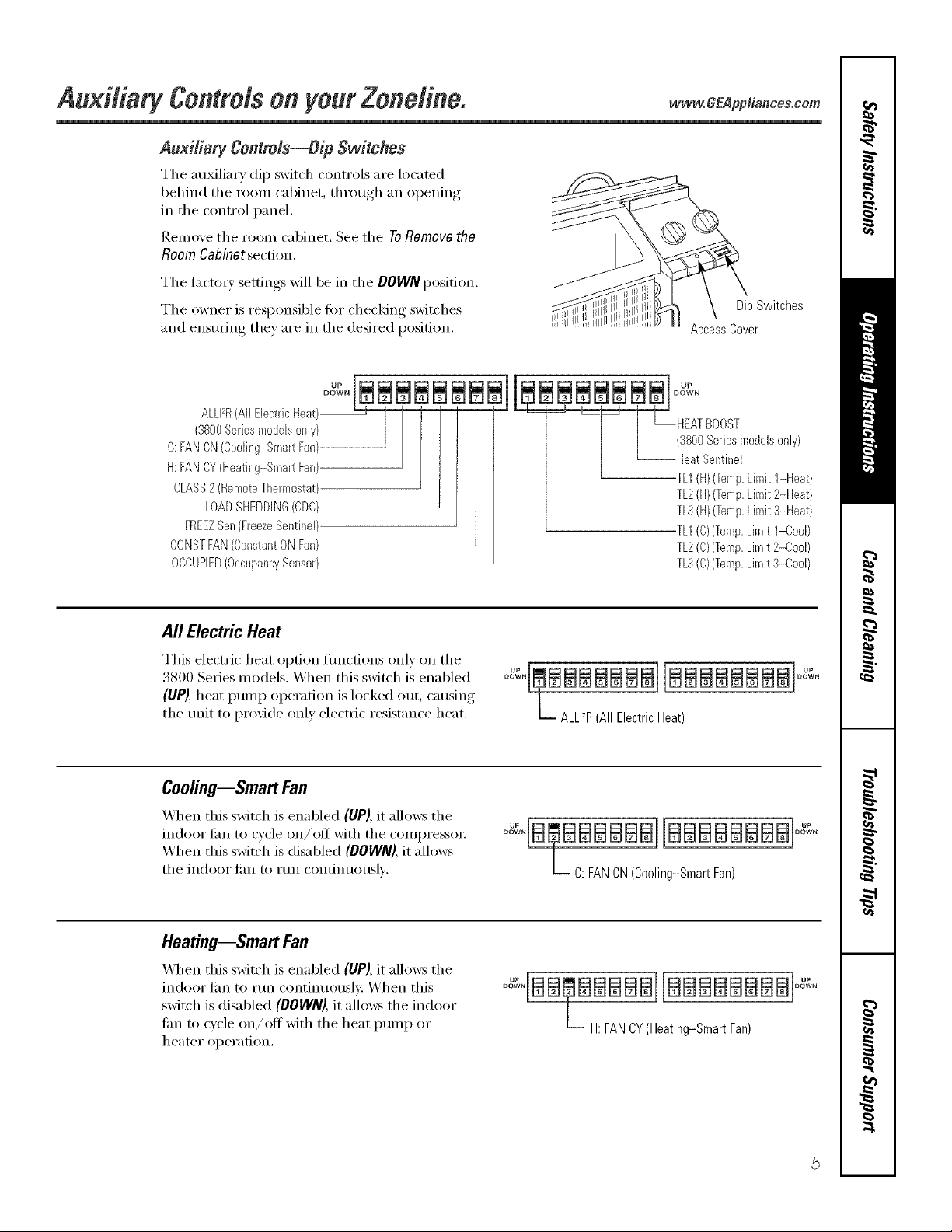
AuxiliarFContrMs--DipSwitches
The au_liary dip switch controls are located
behind the room cabinet, through an opening
in the control panel.
Remove the room cabinet. See the ToRemovethe
RoomCabinetsection.
The ti_cto_) settings will be in the DOWNposition.
The owner is responsible tor checking switches
and ensuring the) are in the desired position.
uP
ALLFR(All Electric Heat)--
(3800Series models only}
C: FAN CN(Coo%g-Smart Fan}
H: FAN CY(Heating-Smart Fan)
CLASS2 (RemoteThermostat)
LOADSHEDDING(CDQ
FREEZSen (FreezeSentinel}
CONSTFAN(Constant ON Fan)
OCCUPIED(OccupancySensor)
DipSwitches
AccessCover
DUwPN
HEATBOOST
(3%0 Series modelsonly}
Heat Sentinel
TL1(H)(Temp.Limit 1-Heat)
TL2(kl)(Temp.Limit 2-kleat)
TL3(HI (Temp.Limit 3-Heat)
TL1CO)(Temp.Limit I-Cool)
TL2(C)(Temp,Limit 2-Cool/
TL3(C/(Temp,Limit 3-Cool/
All Electric Heat
This electric heat option flmcfions only on the
3800 Series models. _._en this switch is enabled
(UP), heat pump operation is locked out, causing
the unit to provide only electric resistance heat.
Cooling--Smart Fan
_,_l_en this switch is enabled (UP), it allows the
indoor tim to cycle on/offwith the compressor:
\,_l/en this switch is disabled (DOWN),it allows
the indoor Jilil [0 I'Un contintlo/ISlV.
Heating--Smart Fan
When dds swkch is enabled (UP), k allo_s d_e
indoor tim to run continuousl): When this
switch is disabled (DOWN), it allows the indoor
tim to cycle on/off with the heat pump or
heater opei';ition.
° "L, BBBBBBBI[BBBBBBBBI° "
L ALLFR (All Electric Heat)
o qa BBaBBaJjaaBBaaBa]o ,,
L C: FAN CN (Cooling-Smart Fan)
BBBBBBBB]
OH: FAN CY (Heating-SmartFan)
Page 6
AuMtiary contrMs on your Zone#he.
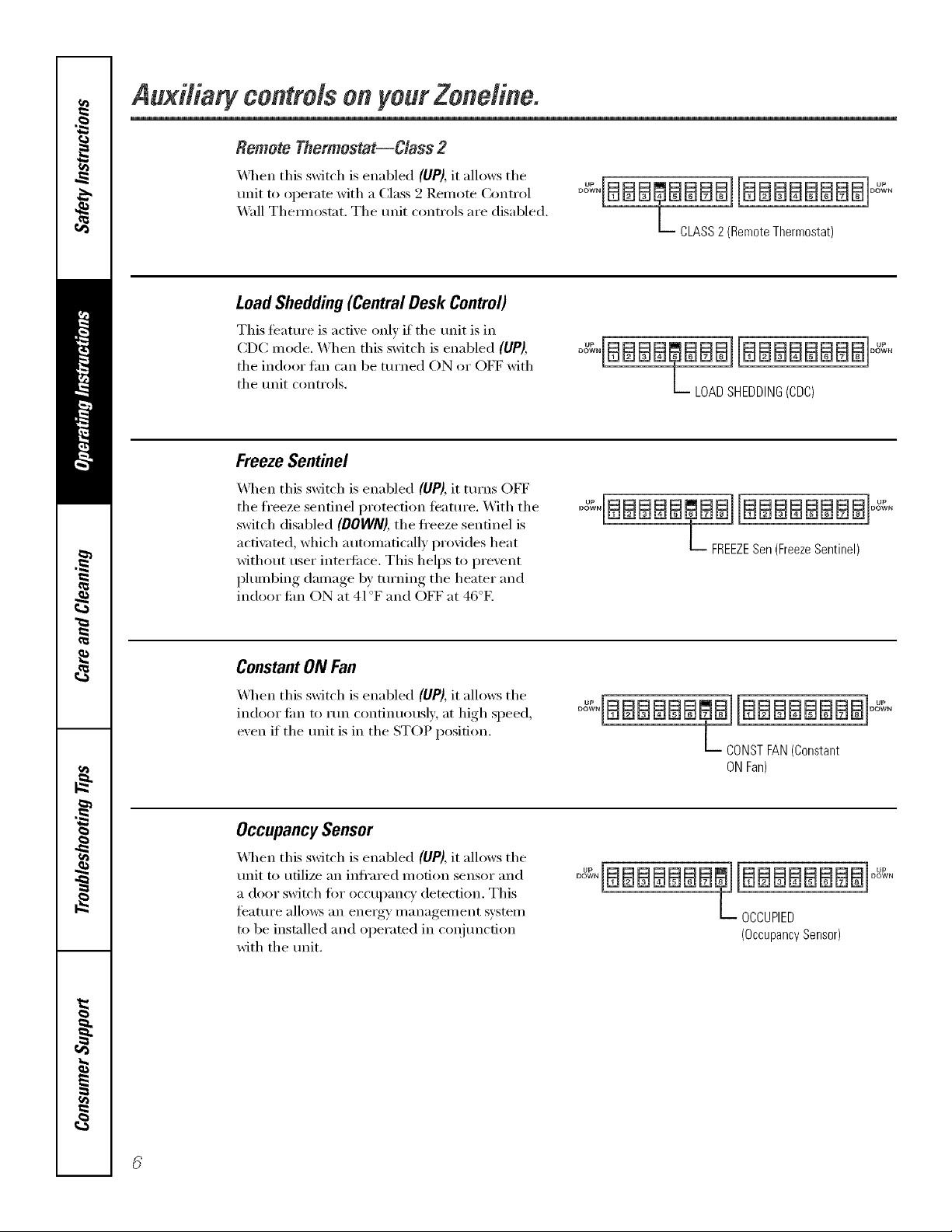
Remote Thermostat--Class 2
_._q_en this switch is enabled (liP), it allows the
unit to operate with a Class 2 Remote Control
Wall Them_ostat. The unit controls are disabled.
LoadShedding(CentralDesk Control)
This feattu'e is active only if the unit is in
CDC mode. When this switch is enabled (UP),
the indoor tim can be turned ON or OFF with
the unit controls.
Freeze Sentinel
_._l_en this switch is enabled (UP), it turns OFF
the fl'eeze sentinel protection ieature. With the
switch disabled (DOWN),the fl'eeze sentinel is
acti\_ted, which automatically provides heat
without user inte_ti_ce. This helps to prevent
plumbing damage by turning the heater and
indoor tim ON at 41°F and OFF at 46°E
°"qBBB@BBBBBBBBBBBB1°"_"
L CLASS2 (Remote Thermostat)
°"_°BBBB@BBBBBBBBBBB°"_°
L LOAD SHEDDING(CDC)
°_°IBBBBB@BBIBBBBBBBB °_°
L FREEZESen(FreezeSentinel)
Constant ON Fan
_q_en this switch is enabled (UP), it allows the
indoor tim to run continuously at high speed,
exen if the unit is in the STOP position.
OccupancySensor
xAl_en this switch is enabled (UP),it allows the
unit to utilize an infl'ared motion sensor and
a door switch tot occupancy detection. This
tbature allo_vs an energy nmnagelnent system
to be installed and ope_wted in coqiunction
with the tmit,
L CONSTFAN(Constant
ONFan)
"_BBBBBBBB
OCCUPIED
(OccupancySensor)
Page 7
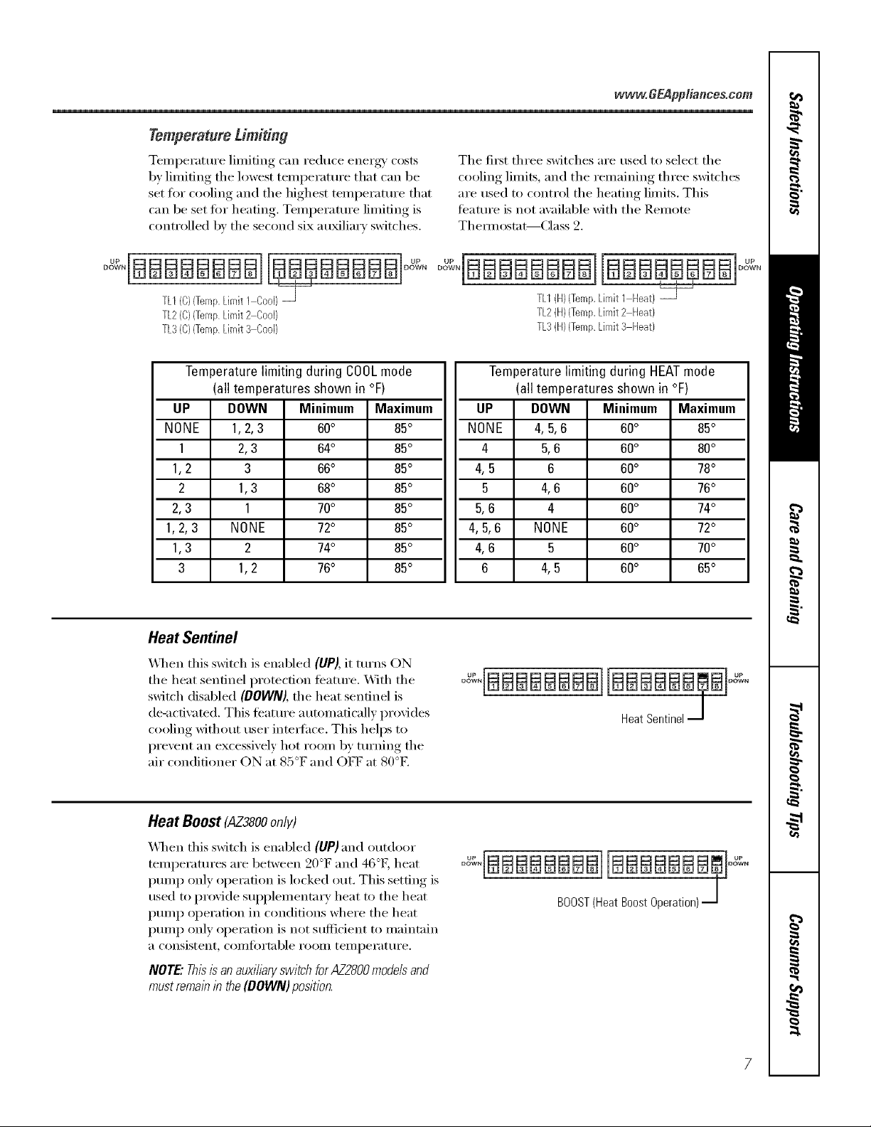
Temperature Limiting
TemI)erature limiting can reduce energy/costs
by limiting the lowest temperatm'e that can be
set for cooling and the highest temperatm'e that
can be set fi)r heating. Temperature limiting is
controlled by the second six auMliarv switches.
TL2(C)(TempLimit2 CooJ)
TL3(C}(TempLimit 3 Cool}
ww'w.GEApp#ences.com
The fit_t three switches are used to select the
cooling limits, and the remaining three switches
are used to control the heating limits. This
teatm'e is not available with the Remote
Them_ost;_t--Class 2.
TLI{H){Temp,LimitI [-[eat)
TL2{H}{Temp,Limit2 [-[eat)
TL3(H)(TempLimit3 Heat)
Temperature limiting during COOLmode
(all temperatures shown in °F)
UP DOWN Minimum Maximum
NONE 1,2,3 60° 85°
1 2,3 64° 85°
1,2 3 66° 85°
2 1,3 68° 85°
2,3 1 70° 85°
1,2,3 NONE 72° 85°
1,3 2 74° 85°
3 1,2 76° 85°
Heat Sentinel
X&l_en this switch is enabled (UP), it turns ON
the heat sentinel protection ti_atm'e. _]th the
switch disabled (DOWN), the heat sentinel is
de-activated. This teatm'e automatically provides
cooling without user intedhce. This helps to
prevent an excessively hot room by turning the
air conditioner ON at 85°F and OFF at 80°E
Temperature limiting during HEATmode
(all temperatures shown in °F)
UP DOWN Minimum Maximum
NONE 4, 5,6 60° 85°
4 5,6 60° 80°
4,5 6 60° 78°
5 4,6 60° 76°
5,6 4 60° 74°
4,5,6 NONE 60° 72°
4,6 5 60° 70°
6 4,5 60° 65°
o 'IBBBBBBBBBBm.BIo "
HeatSentinelJ
Heat Boost (AZ38OOonly)
When this switch is enabled (UP) and outdoor
temperatures are between 20°F and 46°[h heat
pmnp only operation is locked out. This setting is
used to provide sui)plementary heat to the heat
pmnp operation in conditions where the heat
pmnp only operation is not sufficient to maintain
a consistent_ coi//t()rtable i'ooiil [eii/l)ei'_lt/li'e.
NOTE."Thisis an auxiibry switch for AZ2800mode# and
mustremab b the (BOWN) position.
° :'IBBBBBBBBI[BBBBBBBm]o :"
BOOST(HeatBoostOperation)J
Page 8
Auxiliary controlsonyourZoneline.
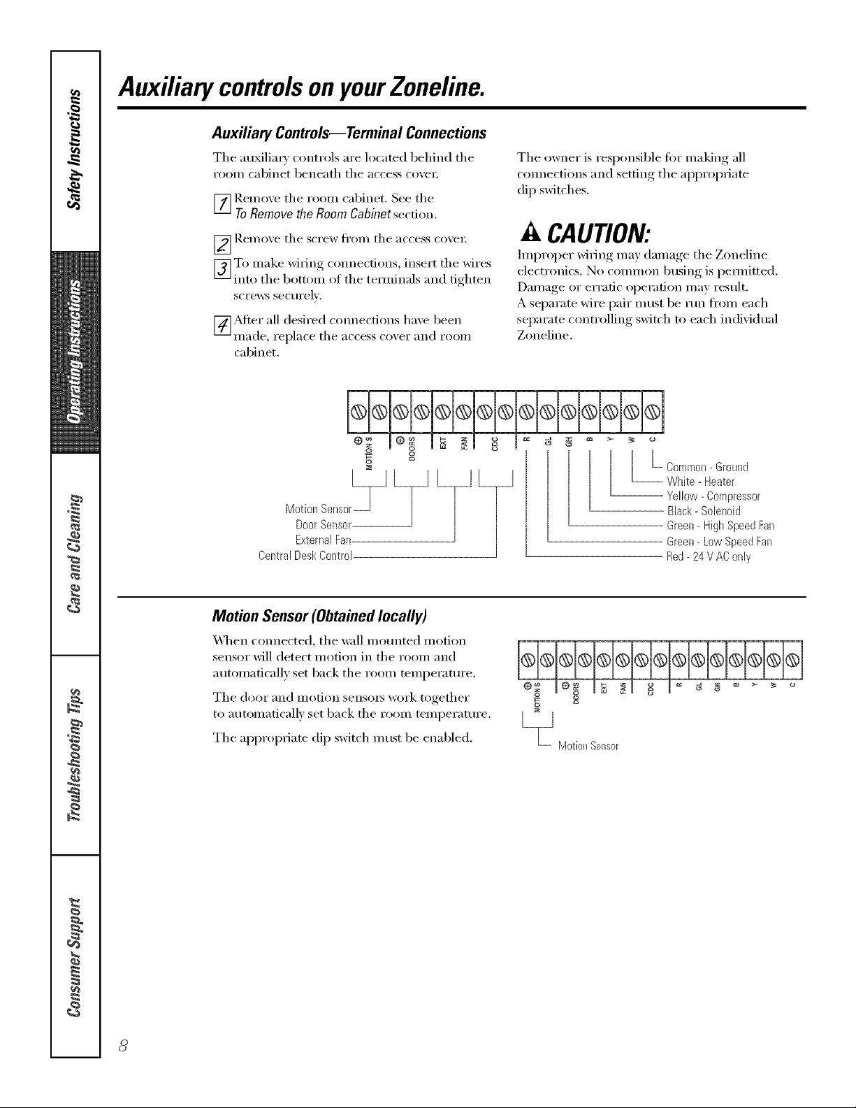
Auxiliaq Controls--Terminal Connections
Tile auMlia_ controls are located behind tile
rooiil cabinet beneath tile access coxei;
_] Remoxe tile room cabinet, See tile
ToRemovethe RoomCabinetsection.
_ Rei/loxe tile S(TeW tl'OIll tile }l('('ess ('o_ei;
[_]To make wi_ing c(mnecfions, inse_L tile wires
into tile bottom of tile tem_inals and tighten
screws sectlrelx,
[_Mter all desired connections have been
Illade, replace tile access coxer }lIl(l rooi/l
cabinet.
The owner is responsible fi)r making all
c(mnections and setting tile appropriate
dip switches.
A CAUTION:
Improper wi_ing may damage tile Zoneline
electronics. No common busing is pem_itted.
Damage or erratic operation may restflt.
A separate wire pair must be run fl'om each
separate controlling switch to each individual
Zoneline,
S
Door Sensor
External Fan
Central Desk Control
Motion Sensor(Obtainedlocally)
_41/en c(mnected, tile wall mounted motion
sensor will detect motion in tile room and
automatically set back tile room temperattu'e.
The door and motion sensors work together
to automatically set back tile room temperature.
Tile appropriate dip switch m list be enabled.
L_ Motiel_Sensor
L Common- Ground
-- White - Heater
Yellow - Compressor
Black - Solenoid
Green- High Speed Fan
Green- Low Speed Fan
Red- 24 V AC only
g I = g g
ca
Page 9
Door Sensor (Obtained locally)
_]/en connected, tile door sensor will detect
when tile door in tile i'OOill w;is opened or
closed. This teature nmst be used in coi_junction
with tile motion senso_:
Tile door and i/lotion sensoi3 work together
to automaticall_ set back tile room temperature.
%
External Fan(Obtainedlocally)
_4]/en connected, an auxiliary or external tim
can be controlled with tile indoor tim motor
on tile Zoneline. Com_ections provide 94 V AC
to energize a remora rela 5 turning on tile
external tim. g
Central Desk Control
m
S
L_ DoerSensor
www.GEAppliances.com
[__1
"L ExternalFan
_&l/en com_ected, tile refit can be turned ON
or OFF with a switch located at tile Central
Control Panel. A separate wire pair nlust be
rtm fl'om each separate controlling switch to
each individual Zoneline.
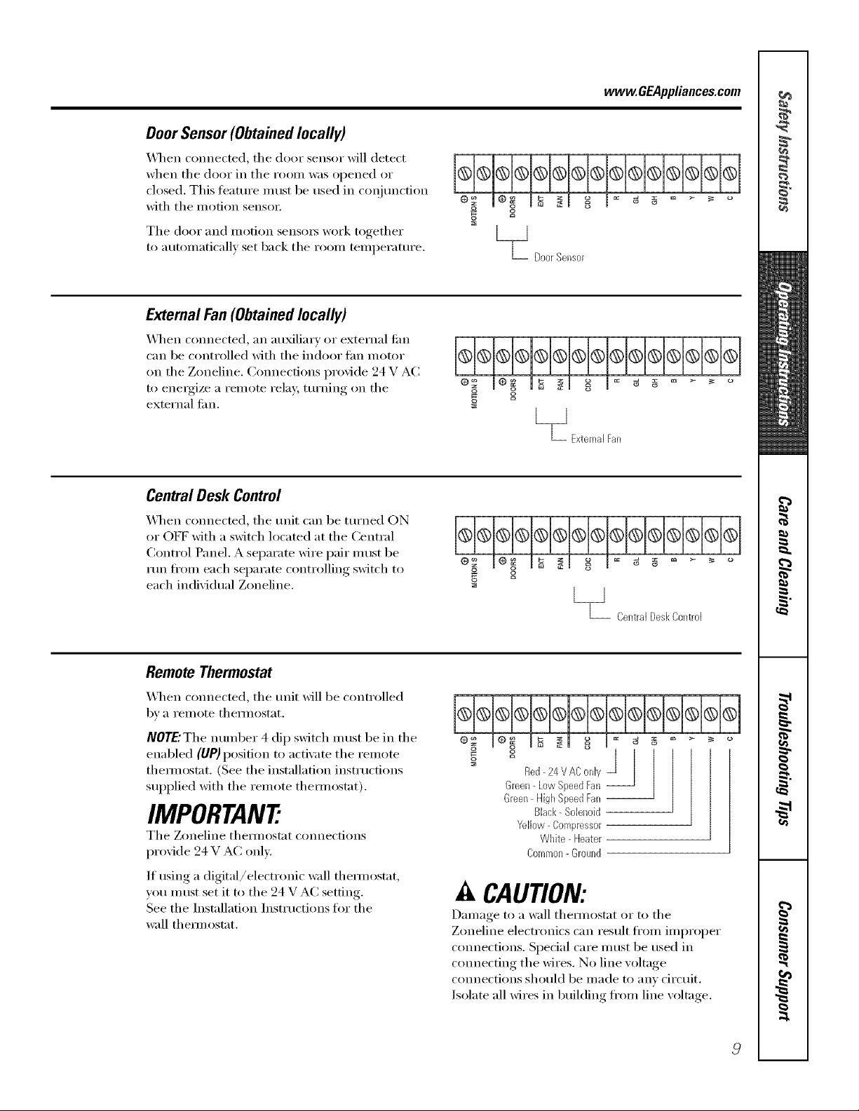
Remote Thermostat
X_q/en connected, tile trait _fill be controlled
bv a i'eillote thermostat.
NOTE'The number 4 dip switch must be in tile
enabled (UP) position to activate tile remote
themlostat, (See the installation instructions
supplied with tile remote themlostat).
IMPORTANT:
Tile Zoneline them/ostat connections
provide 24 V AC only.
If using a digital/electronic wall themlostat,
you must set it to tile 24 V AC setting.
See tile Installation Instructions fin" tile
wall them/ostat.
[__J
_- CentralDeskCol_troJ
Red- 24 V AConly
Green-Low SpeedFan --
Green HighSpeedFan--
Black- Sobnoid
Yellow Compressor
White- bleater
Common-Ground
J
A CAUTION:
Damage to a wall themlostat or m tile
Zoneline electronics can result fl'om improper
com_ections. Special care nlust be used in
cmmecting the wires. No line voltage
connections should be made to anv circuit.
Isolate all wires in building ti'om line voltage.
Page 10

Careand cleaning.
Room Cabinet and Case
Turn tile Zoneline off and disconnect tile
power supply:
OutdoorCoils
Tile coils on tile outdoor side of tile Zoneline
should be checked regularly. If tile)' are clogged
with dirt or soot, they may be protessionally
steam cleaned, a service a\_dlable through your
GE se_Mce outlet. You will need to remove the
unit to inspect tile coils because tile dirt
buildup occm_ on tile inside.
To clean, use water and a mild detergent.
Do not use bleach or abrasives. Some commercial
cleane_ may damage tile plastic parts.
Coils
Grille
Clean the outside coils regularly.
Base Pan
In some installations, dirt or other debris may be
blown into tile unit fl'om tile outside and settle in
tile base pan (tile bottom of tile trait).
Ventilation Filter
If the ventdoor isopen,dean the ventfiiter twice a year
or as require_
TurntheZoneiibeoff before cieaning.
Toremove the vent filter:
• Remove tile room cabinet. See tile ToRemove
the Room Cabinet section.
• ReIllOve tile tk)/li" S(i'e_:s se('tli'ing tile tlIlit
flanges to the case.
• Slide tile trait fl'om tile wall case.
• Grasp tile vent filter tab and pull tile filter ()tit
by sliding it to the right.
In some areas ot tile United States, a "gelqike" or
"slime-like" substance may be seen in tile base pan.
Check it periodically and clean, if necessmT:
Toclean the ventfilter:
• Run water through tile filter ti'om tile
back side.
• D_y thoroughly betore replacing.
10
Page 11

Tomaintain optimum performance, clean the filters at least every 30 days.
Air Filters
To remove the air filters:
www.GEAppliances.com
2Air filters
Puii
Dirty filter--Needs cleanflTg Clogged filter--Greatly
Turn the Zoneline off before cleaning.
The most iml)ortant thing you can do to
maintain the Zoneline is to clean the filter
at least every 30 days. (;logged filte_ reduce
cooling, heating and air flow.
Keeping these filters clean will:
• Decrease cost of operation.
• Sa;'e energy:
• Prevent clogged heat exchanger coils.
• Reduce the risk of prematm'e component
fifilm'e.
To clean the air filters:
• Vacuum off' the heavv soil.
•Rtm water through the filte_ ti'om the
back side.
reduces cooling, heating
andairflow.
• D_T thoroughly heft)re replacing.
/VOTE:Theair filte_ are interchangeable
and will fit in either the right or left side.
Toreplace the air filters:
Pushdown
_IL CAUtiON: Donot operatethe
Zonelinewithout the filters inplace.Ira filter
becomestorn or damaged,it should bereplaced
immediately.
Operating without the filte_s in place or with
damaged filte_ will allow dirt and dust to reach
the indoor coil and reduce the cooling, heating,
airflow and efficiency of the refit.
Replacement filtex_ are awfilable fl'om yore"
salesperson, GE deale_; GE Service and Parts
Center or authorized Customer Care '_se_'icers.
//
Page 12

Installation
Zoneline Air
Instructions
Conditioners
Questions?Call 800.GE.CARES(800.432.2737)orVisitour Website at: www.GEAppliances.com I
BEFORE YOU BEGIN
Read these instructions completely and carefully.
• IMPORTANT - S_,,ethese
instI uctions for h)cal inspector's use.
• IMPORTANT - Obse_,'e_,.
governing codes and ordinances,
• Note to Installer - Be sure to leave these
instluctions with the owner.
• Note to Owner - Keep these instructions tor
fllture reii_rence.
" Proper installation is the responsibili W of the
installer,
• Product taihu'e due to improper installation is not
covered trader the _'arrantv.
TOOLS YOU WILL NEED
Phillipsscrewdriver
IMPORTANT ELECTRICAL
SAFETY--READ CAREFULLY
_k CAUTION:
• Follow the National Electrical Code (NEC) or local
codes and ordinances.
• For personal safety, this Zoneline must be properly
grounded.
• Protective devices (fuses or circuit breakers)
acceptable for Zoneline installations are specified
on the nameplate of each unit.
• Do not use m_ extension cord with this refit.
Aluminum building wiring may present special
problems--consult a qualified electricim_.
When the unit is in the OFF position, there is
still voltage to the electrical controls.
Discmmect the power to the unit before
servicing by:
1 Removing the power cord (if it has one) from
the wall receptacle.
OR
2 Removing the branch circuit fuses or turning
the circuit breakers off at the panel.
ZONELINE COMPONENTS
Exteriorgrille/louver**J
Wallcase**_--}
Shipped with the Zoneline unit
Checkthe "Essential Elements" list on the unit
m cabinet*
F Zoneline unit
-Power supplykit....
12
Page 13

Installation Instructions
REPLACING AN EXISTING UNIT?
Check the "Essential
Elements" label for
importantinformation.
Use the correct wall case
This unit is designed to be installed in a GE plastic or
insulated metal wall case. This mininfizes condensation
from limning on the room side of the case.
If the current wall case is not insulated, you can reduce
the possibility of condensation limning by installing
insulation kit ]_Kg01 i,, a\_filable where you pmvhased
the unit.
NOT[:: There are several extra holes in the refit side
flanges fin" installation in _:dl cases other than GE.
To avoid damaging the flange insulation, the inst;dler
should use an awl or other shaq) tool to imncmre the
insulation in the appropriate holes befln'e installing
the attachment scre_vs.
Replacing a ducted unit
New ducted installation:
If this unit is to be installed in a new ducted application
using a duct adapter kit, the kit must be installed before
the refit is placed in the wall case. The installation
instructions are packed with the kit.
plate
Existing ducted installation:
Replacement of an existing ducted refit may require
different components. Request this infimnation ti'om
w)ur sales representative.
• Replacing 230/208 volt milts:
See page 14,
• Replacing 265 volt milts:
See pages 15 and 16.
Use the correct outdoor grille
You should use the outdoor grilles shown on the
"Essential Elements" label on the top of the unit.
• ]fan eMsting grille is not replaced, capaci D' and
eflidencv will be reduced and the refit may tail to
operate properly or tifil prematm'ely. A deflector kit,
I_L_K40, may be used with grilles that were not
designed fin" yore" new GE Zonelines. The ILM(40
contains air deflectms and gaskets that motmt to the
refit to direct the hot exhaust air away fi'om the air
intake to allow the refit to fimction properly. The
grille must have a 65% minimum fl'ee area.
• Any vertical detlectms in the existing rear grille should
be removed to decrease condenser air recirculation
that can cause the unit to "short-cycle" and lead
to pi'eli/attli'e COlilponent fifilure.
Use the correct power cord
I,ocal codes may require the use of arc thult or
leakage current detection devices on 230/208 volt
installations.
13
Page 14

Installation Instructions
230/208 VOLT ELECTRICAL SUPPLY
HOW TO CONNECT
1 Remove the room cabinet.
2 Connect to electrical power.
3 See the special instHmtions below fin" applicable
suI)ply voltages.
4 Reinstall the room cabinet.
A power supply kit must be used to supply power to fl_e
Zoneline unit. The apl)ropfiate kit is dete_nined by the
voltage, the means of electt_ical connection and the
amperage of the branch circuit.
Power supply kit
Connections of 208 or 230 volt circuits may be with a
power sui)pl ) kit or ajunction box kit.
All wiring, including installation of the receptacle,
must be in accordance with the NEC and local codes,
ordinances and regulations. I,ocal codes may require
the use of an arc tault or leakage current detection
device on the power cord. Be sure to select the
correct cord fin" wmr installation.
Power cords may include an arc fault interruption or
a leakage current detection interruption device, A
test and reset button is provided on the plug case or
the inline case, The device should be tested on a
periodic basis by first pressing the TEST button and
then the RESET button, If the TEST button does
not trip or if the RESET button will not stay engaged,
discontinue use of the Zonelh_e and contact a
qualified service teclmician,
Order Kit RAK4002A for 230/208 _olt direct
connection,
I
IF USING AN ELECTRICAL
SUBBASE
230/208 xolt models ma) be installed using one of
the fi_llowing electrical subbases:
Branch Circuit and Proper GE
UnitAmperage Bating Subbase Kit
15 ]L_K204D15P
20 ]L_K204D20P
30 ]_IZ,204D30P *
*Not approved tbr use on 7000 BTU models.
Electrical subbases provide an enclosure fin +direct
connection or enclosed receptacles. The subbase kit
includes the power cord.
I
© © @
Tandem Perpendicular Large Tandem
15Amp. 20Amp. 30Amp.
230/208volt receptacle configuration.
Branch Circuit and Proper GE Power Cord
UnitAmperage Bating with LCDI Device
15 RA1(3153
20 ]L_I(3203
30 1_&K3303'::
':Nol approxed tor use on 7000 BTU models.
The instructions provided with the selected subbase kit
must be carefifllv tollowed. It is the resi)onsibilit'y of the
installer to ensure the connection of components is
done in accordance with these instructions and all
electrical codes.
14
Page 15

Installation Instructions
265 VOLT ELECTRICAL SUPPLY
/k WARNING:
Connection of this 265 V AC product to a branch circuit
MUST be done b) direct connection in accordance with
the National Electrical Code. Plugging this unit into a
building mounted exposed receptacle is not permitted
b) code.
These models must be installed using the ai)propriate
GE power supi)l } kit tor the branch circuit amperage
and the electrical resistance heater wattage desired.
Use the POWER CONNECTION CHART on page 17
to determine the correct kit required. One of the
following installation methods (A or B) must be used.
HOW TO CONNECT
1 Remove the room cabinet.
2 Connect to electrical power,
3 See the special instructions below fi}r applicable
supply voltages.
4 Reinstall the room cabinet.
A. FOR SUBBASE INSTALLATION
Electrical subbase kits are a_ailable to provide a flexible
enclosure fi)r direct connection,
Branch Circuit and Proper GE Power
UnitAmperage Rating Subbase Kit Supply Kit
15 ILM4204E 15 ILM(5172
20 IL_K204E20 1L_I(5202
30 IL_K204E30 1L_I(5302
The instructions pr{Mded wifll the selected subba_ kit must
be cm'efid b tbllo_vvd. It is the responsibilit) of the installer
to ensure the connection of COlnponents is done in
accordance with these insu'ucfions and all elecu'ical codes.
[] REMOVE JUNCTION BOX
1 Remo_e tbe.jm_ction box cover b) removing the
l-roi]t two screws.
2 Remo_e tbejm_ction box by removing the top and
bottom rear screws. Note bow the tabs on the lower
left side of the jm_ction box se,we to bold the side in
place. This wi!l help when the box is being reinsm!led.
Unitconnector
Junction Junction
boxcover box
[] CUT AND STRIP THE CORDSET
1 I-_,emove the cordset ti'om the power supply kit.
Measure G" down the cord fl'om where it elnerges
fix)in the back of the nylon plastic connector
and cut the cord througl] at this point,
2 Careflfllv relnove 3" of the cordset insulation
so as to expose the three insulated wires.
3 Strip 3/4" of the insulation away at the end
of each of the three wires (i.1, Neutral and
Ground). Plug the connector fldlv into place
in the unit mating connector. Be sure the
locking tabs at the sides are engaged.
3/4"
B. FOR DIRECT CONNECT
INSTALLATION
If an electrical subbase is not used, direct connection t()
branch circuit wiring inside the provided junction box must
be done in accordance with the following steps.
15
NOTE: Order Kit RAK4002(A,_ to enable a quick I
disconnect inside the junction box.
I
I
I
Page 16

Installation Instructions
265 VOLT ELECTRICAL SUPPLY
[] ATTACH CONDUIT
1 Use the round knockout at the botton/of the
junction box to attach conduit coming from the
branch circuit. Remove the knockout, attach the
conduit and bring wires into the junction box.
i,eave 6" of wire flee at the end of the conduit
to allow connections to be iilade.
C0nduit
2 If a fllse and fllseholder are to be used, the
knockout at the top of the box is tor mounting
a Buss Fuseholde_: Be sure the fllse and fllseholder
are of the same rating as the branch circuit.
I,eadwires at the fl/se can be either soldered in
place or ammhed using UIAisted 1/4" female
(receptacle) crimp connector5.
[] REINSTALL JUNCTION BOX
• Reinstall the junction box by engaging the left tabs
on the lower right ta(e oI the unit, aligning the
screw holes at the top and bottom and drMng the
two screws until secme. Be sure that all wire leads
are inside the box and not pinched between the box
and the unit. The green insulated ground wire from
the unit MUSTbe connected to the branch circuit
ground Mre.
Make all wire connections by using al_l_ropriate
/_)IAisted electrical connectoi_ and techniques
(black to black, white to white and green t() green).
[] REINSTALL JUNCTION
BOX COVER
1 Careflflly rock all wires and connecti(ms back inside
the junction box. Be sure there are no loose
connections or stray uninsulated wires exposed.
2 Place the junction box cover in place. Replace the
two sci'e_:s removed earlier and tighten securely.
16
3 Discard the unused portion of the plug and
the cordset.
Page 17

Installation Instructions
POWER CONNECTION CHART
230/208 Volt
Power Supply Kits
with Leakage
Current Detection
Device
RAK3153
RAK3203
RAK3303*
265 Volt
Power
Supply Kits
RAK5 ]72
RAK5202
RAK5302*
*Not approxed for use on 7000 BTU models.
T_I I1 d eI/l
Perpendicular
I,arge Tandem
Wall Plug
Configuration
Does Not Apply
Does Not Apply
Does Not Apply
Heater Wattage
Circuit Protective Device
20 Amp Time Dela'_ Fuse or Breaker
15 Amp Time Delay Fuse or Breaker
30 Amp Time Delay Fuse or Breaker
(O)230/208 Volts
Heater Wattage
Circuit Protective Device @ 265 Volts
20 Amp Time Dela'_ Fuse or Breaker
I 15 Amp Time Dela'_ Fuse or Breaker
30 Amp Time Delay Fuse or Breaker
2,55/2.09 K\,\
35
• .4:/2.82 K_A
5.00/4.10 K\_
2.a: K_4
3.45 K_4
5.0 K\4
17
Page 18

mnstamiation mnstructions
INSTALLING THE ZONELINE
[] iNSTALL THE WALL CASE AND
EXTERIOR GRILLE
The RAB71 series or RAB77 wall case must be
properl} im_stalled per im_st_l_ctio_s packed with
the case.
* Remove the corrugated stif[e_er m_d tl]e ol_tdoor
protective pam_el. [ !se the slit im_the ol_tdoor pm_el
as a ham_dhold amid push out.
Pro
panel
Stiffenel
* h]staH the exteiJor grille h'om the I"ooF_) side
followim_g im_st_l_ctio_s packed with the g_tille.
Insulated Wall Case
This m_it is designed to be im_sta]led im_a GE plastic
or am_im_sulated stee] wall case_ This mil]imizes
coildemlsatiol? f}'om fk)rmimlg oral the room side of
the case.
The IL£B71 series wail cases are im_suIated, h_suL_tiom_
kit RAI;S)01I, is available fiw i_se with RAB77 or
existim_g m_im_su]ated wall cases whem_ m_eeded.
NOTE: For i_sta]latio_ with a subbase or duct adapte_;
see the i_st_uctio_s packed with those ]<its.
[] PREPARE THE UNIT
• Carefully remove shipping tape and loam shipping
blocks from the room cabinet, compressor and
vent doo_: There may be multiple blocks and pieces
ot shipping tape that need to be rein(wed.
Shippingtape
(Locationsmayvary)
• Remove the room cabinet by pulling it out at the
bottom to release it (1), then lift it up to clear the
rail along the unit top (2).
O
O
• If vent door is to be operational, remove shipping
screws ti'om the ti'ont side of the xent doo_; if present.
18
Removetwo
shippingscrews
Page 19

Installation Instructions
[] iNSTALL THE UNiT iNTO THE
WALL CASE
Slide the m_it im_to the wail case a_]d secm'e with fi_m"
ScI'ev/s tbml_gh the m_it flm_ge boles.
NOT]?:: There are several extra holes in the refit side
flanges for installation in wall cases other than GE.
To avoid damaging the flange insulation, the installer
should use an awl or other shaq) tool m puncture the
insulation in the appmp_iate holes before installing
the attachment scrm_:s.
[] REPLACE THE ROOM CABINET
Reinstall the room cabinet b_ hooking the top (:,'_er
the rail ahmg the unit top (l), then I)ushing, it in at
the bottom (2).
19
Page 20

Installation Instructions
OPTIONAL--DRAIN KIT INSTALLATION
Dry Air 25 Series models are designed to improve dehumidification by 25%. Since more moisture will be removed from
the air, there is a greater possibility that water will drip from the wall case thml with a standm'd unit. To prevent this water
from dripping onto external building walls, we recommend the use of RAD10 Drain Kit.
External Drain
See the Installation Instructions
in the RADIO kit.
Alternate:
6"long, 1/2" O.D. straight
coppertube
/
Internal Drain
See the Installation Instructions
in the RAD 10 kit.
Squaredraini_oles
""e "_e_,_ Type"A" screwformetalcaseor
1/2" O.D.draintube t _I" _'"_
Neoprenespongegasket /
Steelmountingplate
Type"B"screwfor moldedcase
Squaredrainholes
Neoprenespongegasket /
Steelmountingplate
"" _'-_ _ql-_ Type"A" screwfor metalcaseor
Type"B"screwfor moldedcase
2O
Page 21

TrOubleshooting -tips
Save time and money! Review the charts on the following
ages first and you may not need to call for service.
Problem Possible Causes What To Do
Zoneline does The mlit is * Make sure tile Zoneline plug is pushed coml)letely
notstart unplugged, into tile outlet.
The power cord is not * Rem_we tile room cabinet and make sure that tile
firmly attached, vellow connector on tile end ot tile power cord is
fimdy engaged.
The fuse is blown/drcuit * Check the house fllse/drcuit breaker box and replace
breaker is tripped, the fllse or reset the breakeI:
The refit is waiting for • This is nomml. Tile Zoneline will start again after
the compressor overload it resets.
protector to reset.
Power failure.
• If power tifihu'e occtu_, set tile mode control to STOP.
"_._hen power is restored, set tile mode control to tile
desired setting.
• There is a protective time delay (up to 3 minutes) to
prevent trii)ping ot tile compressor overload. For this
reason, tile unit may not start noi_nal heating or cooling
tor 3 ininutes alier it is turned back oil.
The current interrupter
device is tripped.
• Press the RESETbutton located on tile power cord plug
or tile box near tile plug.
• If tile RESETbutton Mll not stay engaged, discontinue ttse
of the Zoneline and contact a q/alified seiMce technician.
Zonetine does not cool Indoor airflow • Make sure there are no curtains, blinds or flu'niture
or heat as it should is restricted, blocking tile ti'ont of tile Zoneline.
Outdoor airflow is
restricted or recirculated.
• Make sure tile rear grille is not restricted. This can
cause tile unit to cycle off due to tile colni)ressor
ox erload protector.
• Outdoor grille must have a minimum of 65% flee area.
Non-GE grilles ma x be too restrictixe fin" proper
i)erfimnance. Consult }our salespei_on fin" assistance.
The temp control may • Turn tile control to a lower or higher setting.
not be set properly. NOTE:Thetemperaturebmitermaybe bruitingthetemperaturerange.
The air filter is dirty. • Clean tile filter at least eveIT 30 days.
See tile Operating Instructions section.
The room may have • When the Zoneline is fii_t turned on you need to
been hot or cold. allow tilne tor tile rooln to cool down or WalIn up.
Outdoor air is • Set tile vent control to tile closed position.
entering the room.
Burning odor at the start
of heating operation
Dust is on the surface
of the heating element.
• This can cause a "burning" odor at tile be,tinning of
tile heatino_ oi)eration. This odor should quickly fade.
21
Page 22

BeforeFoucall forservice...
Problem Possible Cagses What To Do
The air is get alwaFe rI_e heat pump is not * This is mmrmaL The heat plm/p will pro&we warm air
operation electric heat Js ilsed.
The fan switches may be
set at cmadrmous fan.
0
This callses the _im to blow room temperatm'e air
evem/ _he_/ the compressor or heater cmles oft.
The co_/ti m/Ilolls ai r m ovem ON/t provides better
overall temperat_lre com/trol ]m/ the cool mode.
There is om/eswitch for coo]im/g am] o_/e switch
for h eati m/g.
The air does not feel
warm enough during
heating operation
The unit is net The fan dip switch may • See the Auxifiary Controls sectiom
blowing out air be set to CYCLE.
The electric heating
feature does net work
The heat pump alone
produces air that feels
cooler than desired.
The power cord is not
firmly attached.
[Ise the Electric Heat ()ptio_/. This mrm/s off the
heat pinup am_ warms with electric heat (m]y_
NOTE: Use of this option wi// resu/t in increased energy
ooilsuFi)pt/of}.
® Remove the room cabim/et am] make sure that the
_ellow co]/m/ector oil tile e]/d of tile power cord is
22
Page 23

Normal Operating Sounds
PING! POP!
' ] /
" @
_'ol_ may heal" a ph]gin_ noise camed by water beh_g
picked I_l) _md through agah_st the tom,denser om_
x_im' days or whe_ the lmmiditv is high. This design
featm'e helps _'emo_ e mo]stm'e amid h_l)_o_ e
"CLICK"
DRIP
6
WHIRl.
k_u ma', hear ]'ela',s click when the controls c_cle
tempemtm'e.
_k'ate]" wi]] collect im_the base [xm (]m'im_ high
h _m_ idi r_ _)r <_n n_i _ _ da_s. Th e water m a_ _we ]'f](_w
a_/d d]'ip f}'om the outdoo]" side of the m/it.
The i_door fire m_s contin_omlv when the m_it is
open]ti_g 1_ the cooli_g mode, m_less the fire s_itch
behh_d the room cabh_et is set at {ira cycle (_[_)_
This wfl] came the {ira to c;de o_ and of_ ruth the
CO]_p_'essoE k'ol_, m_ :_]so ]_ea_" _ {h_ _oise StOp
a_d start.
Yo_ may _otice a fk-w mhmtes de]a_ ]_ starth_g ]fyo_
try to restart the Zo_e]h_e too soon a_ter tm'_h_g it
oft o]" Kvo_ a(!]mt the them_ostat right after the
compressor has s]mt <fiE, This is (h_e to a b_]Ir-i_
restart protector {br the compressor that cruises
a 3-mhmte de]ax
Dmi_g the de{i'ost cycle, both i_door a_d o_tdoor
fires stop a_d the compressor will operate i_ the
cooh_g mode to remove {_'ost from the olltdoor coil.
Alter de{rest, the m]it will restart i_ electric heat to
([_]C]_]7 _r_'_ the room to the desired comtbrt ]eve].
COMPRESSOR
PROTECTION
To protect the compressor a_(]! pre_ ent short
c) c]i_g, the m_it is designed to m_ tbra
o{ B m ]_ii tes a{te r th e corn press or s tarts at a_v
thermostat setth_g.
23
Page 24

Notes,
24
Page 25

Hease phce in envdope and mall to:
GeneralElectric Company
_ran_ Re_stra_on Department
P.O.Box 32150
LouisviUe, KY 40232o2150
25
Page 26

Consumer Product Ownership Registration
Dear Customer:
Thank you for purchasing our product and thank you for placing your confidence in us.
_A/eare proud to ha_e you as a customer!
Follow these three steps to protect your new appliance investment:
Complete mid mail
your Consmner
Product Owuerslfip
Registration today.
t]a_e the peace o/
mind of kin)wing we
can contact you ill
th( unlikely (v(_lt of
a sa/_q_ modification.
AJler mailing tile
registration below,
store this dOCtll//ellt
in a salt, place. It
contains intbrmation
you will need should
you require service.
Our service nmnber is
800.GE.(L\RES
(800.432.2737).
Model Number Serial Number
I I I I I I
Important: If you did not get a registration card with your
product, detach and return the form below to
ensure that your product is registered, or register
online at www.GEAppliances.com.
Consumer Product Ownership Reg
[_tJa(t VO/IF Ownel?'S
Mamml carefulh.
It will help you
operam your new
appliance properly.
, I
._,,,.- Cm h_r<
Serial Number
I,,,,,, , , , , , I I ,
M_: Ms. M*>,. Mix_,
Fi>tl I Lasll
Nmm I I I I I I I I I Name I I I I I I I I I I I I
_11-_. (!1 I
Add r,. ';s I I I I I I I I I I I I I I I I I I I I I I I I
Apt. # I I
Ciw I
l )ale Placed
hi Use ]l]
Monlh
I I I I I I I EqnailAddress*
I I I I I I I I I I
l, l>l, I ,arl, i
0
GEAppl&neos
GE Co_momer & htdIJstrhd
toIJisvilto, I@tltttcky
ww_ 6EApp#_xlces cam
Model Number
I I I I I
, , I
Pholl(
NI/llll)(!r I
* Please provide your e-mail address to receive, via e-mail, discounts, special ottk,p, and other important
communications froln GE Appliances (GEA).
Check here if you do not want to receive commtmications ti-om GEA's careflflly selected partners.
FAII.I RE T() C()MPI.ETE AND RE'F[ RN TttIS CARD DOES NOT DIMINISII Y( )l R
x,_L\RRANTY RIGIH'S.
For intormation about GEA's prixacy and data usage polio?; go to ,,,,avw.GEAppliances.com and click
on 'Prixacv Policy" or call 800.626.2224.
State I , l ,:o_le
Zip I
26
I
I
Page 27

Zoneline Warranty.
All warranty service provided by our Factory Service Centers,
or an authorized Customer Care®technician. Toschedule service,
on-line, 24hours a day, vis# us at www.GEAppliances.com,
or call 800.GE.CARES(800.432.2737).For service in Canada,
call 1.800.361.3400.
For The Period Of."
OneYear
Fromthedate of the
originalpurchase
Five Years
From the date of the
original purchase
FiveYears
Fromthedate of the
originalpurchase
Staple your receipt here.
Proofof the original purchase
date is needed to obtain service
under the warrantg
GEWill Replace:
Anypart of the Zoneline which tifils due to a defbct in materials or workmanship, During this
full one-year warranty, GE will also provide, free of charge, all labor and on-site service to
replace the defecti\'e part,
Any part of the sealed refrigerating system (the compressox; con(lensex; ex;q)orator and all
connecting tubing) which fails due to a (lefe('t in materials or workananship. During this
full five-year sealed refrigerating system warranty, GE will also provide, free of charge, all lal)or
and on-site service to replace the (letecti\'e part,
For the second through Me fifth yearfi.om the date of original pro'chase, GE will replace
certainpartsthat lift] due to a defi_ct in materials or worlunanship. Parts covered are lira
mot(n_, switches, thermostats, heater, heater prote('to_, compressor overload, solenoids,
drcuit boards, au_lia_ y controls, themfisto_s, fl'ost controls, 1(3 ). pump, capadto_s,
vafism_ and indoor blower beating. During this limited four-yearparts warranty, you will
be responsible tin" any labor or on-site service costs.
What GE Will Not Cover:
• Service trips to your site to teach you how to use
the product.
• Improper installation, delivery or ma2mtenaa_ce.
If you have ml h_staJlation problem, or if the air
conditioner is of hnproper cooling capacity for the
intended use, contact your dealer or installer. You axe
responsible for providing adeqwate electrical
commcth_g facilities.
• In commercial locations, labor necessary to move the
unit to a location where it is accessible for service by an
hldJvidual tecluficim_.
• Failure or damage resulting from corrosion due to
hlstallation in ml enviromnent containing corrosive
chemicals.
• Replacement of fuses or resetting of circuit breakers.
This warranty is extended to the original purchaser and any succeeding owner for products purchased for use
within the USA and Canada. In Alaska, the warranty excludes the cost of shipping or service calls to your site.
Some states or provinces do not allow the exclusion or limitation of incidental or consequential damages. This
warranty gives you specific legal rights, and you may also have other rights which vary from state to state or
province to province. To know what your legal rights are, consult your local, state or provincial consumer
affairs office or your state's Attorney General.
• Failure of the product resulting from modifications
to the product or due to tmreasonable use, including
failure to provide reasonable mad necessary
maJlltenaJlce.
• FaJhtre or dmnage resuith_g from corrosion due to
hlstaJlation ha a coastal enviro_maent, except for models
treated with special factory-applied mati-corrosion
protection as designated in the model number.
• Damage to product caused by improper power supply
voltage, accident, fire, floods or acts of God.
• Incidental or consequential damage to personal
property caused by possible defects with this air
conditioner.
• Damage caused after delivery.
Warrantor: General Electric Company. Louisville, KY 40225
27
Page 28

ConsumerSupport.
Haxe a question or need assistance with your appliance? Try tile (;E Appliances _4'ebsite 24 hotu_ a day
"IgEAppliancesWebsite www.GEAppliances.com
any day of tile xear'. For greater comenience and faster service, you can now download Owner's Manuals,
order parts, catalogs, or exert schedule serxice on-line. You can also "_&skOur Team f Expert.
V(X/XX" qtxestions, and so Illuch iilox'e...
O " S i.
ScheduleService
Expert GE repair sexs,ice is onl) one step away fl'om xour doox: Get on-line and schedule your service at
_{xur, conxenience 24 h{xux_ any elm of tile year! Or call 800.GE.CARES (800.432.2737) dudng n{mnal
business houx_.
www.GEAppliances.com
RealLifeDesignStudio www.GEAppliances.com
GE supports tile Uni\'ex_al Design concept--products, services and environments that can be used by
people ot all ages, sizes and capabilities. We recognize the need to design fin" a wide range of physical and
mental abilities and impaimmnts. For details of GE's Univex_al Design applications, including kitchen
design ideas t0r people with disabilities, check out our Website today. Fox" the hearing impaired, please call
800.TDD.GEAC (800.833.4322).
PartsandAccessories www.GEAppliances.com
Individuals qualified to service their own appliances can have parts or accessories sent directly to their
homes (VISA, MasterCard and Discover cards are accepted). Order on-line today, 24 l/otu_ evex'v day or
by phone at 800.626.2002 during nomml business hom_.
Instructions contained in this manual cover procedures to be performed by any user. Other servicing generally
should be referred to qualified service personnel Cautionmust be exercised, since improper servicing may cause
unsafe operation.
ContactUs www.GEAppliances.com
If'you are not satisfied with tile service you receive from GE, contact us on our _.Vebsite with all tile details
including your phone numbex; or write to: General Managex; Customer Relations
GE Appliances, Appliance Park
I,ouisville, KY 40225
Register your new applim_ce on-lble---at your convenience! Timel) product registration will allow for
"l RegisterYourAppliance www.GEAppliances.com
enhanced communication and prompt service under tile terms of_our warranty should tile need arise.
j You may also mail in tile pre-pxinted registration card included in tile packing material, or detach and
use the timn in this Owner's Manual.
Printed in China
 Loading...