

Page 1
©
www.GEAppfiances.com
Safety Instructions ........... 2
Operating Instructions
Air Direction ................ 4
Auxiliary' Controls .......... 5-9
Controls .................... 3
Vent Control ................ 4
Care and Cleaning
Air Filters .................. ] ]
Base Pan .................. ] 0
Outdoor Coils .............. ] 0
Room Cabinet and Case ...... ] 0
Installation Instructions
Electrical Supply ......... ] 4-16
Installing the Zoneline .... 17, 18
Optional Drain Kit .......... 19
Preparation ................ 12
Replacing an Existing Unit? . . .l 3
Heat/Cool Model 2500
Heat Pum[J Modal _500
©
Troubleshooting Tips ....... 20
Normal Operating Sounds .... 21
Consumer Support
Consumer Support . . .Back Cover
Product Registration ...... 25, 26
*A,_rranty .................. 27
Write the model and serial
numbers here:
®
Model #
Serial #
Find these numbers on a label
behind the room cabinet on the
base pan.
49-7415-2 JR 06-01
Page 2
IMPORTANTSAFETYINFORMAtiON.
READALLINSTRUCtiONSBEFOREUSING.
A WARNING!
Foryour safe_ the information in this manual must be followed to minimize the risk of fire or
explosion, electric shock, or to pre vent property damage, personal injury, or loss of life.
_\ "_j____SAFETYPRECAUTIONS
_y_ • This Zoneline must be properly
installed in accordance with the
Installation Instructions before it is
used. See the Installation Instructions
in tile back of this manual.
• hnmediately repair or replace all
electric service cords that have become
frayed or otherwise damaged.
• Unplug or disconnect the Zoneline at
tile fllse box or circuit breaker before
making any repairs.
NOTE: ¼:e strongly recommend that any
servicing be performed by a qualified
individual.
READANDFOLLOWTHISSAFETYINFORMAtiONCAREFULLY.
SAVETHESEINSTRUCtiONS
Replacing an existing un#?
For details, see the Installation
Instructions in this manual.
2
Page 3
Aboutthe controlsonyourZoneline. _.GEA..li..ces.com
LOW
FAN
STOP°° °'_2."
AUTOA _f_ t_ 'A AUTO
HEAT"! I I yCOOL
HIGHAll I I IIA HIGH
HEATw_,. COOL
MODECONTROL
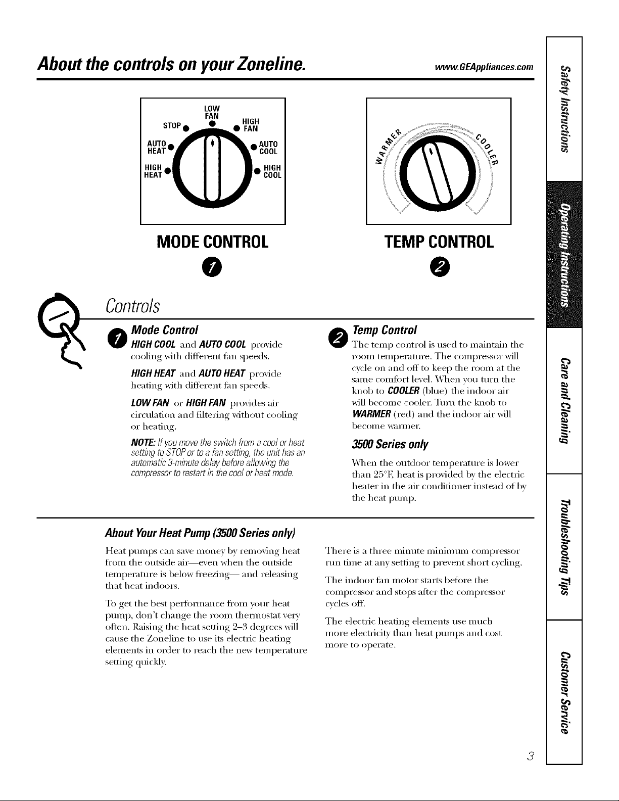
Mode Control
(_ Co_trols
HIGH COOL and AUTO COOL proxide
cooling with different fire speeds.
HIGH HEAT and AUTO HEAT proxide
heating with different tim speeds.
LOWFAN or HIGH FAN provides air
circulation and filtering without cooling
or heating.
NOTE: Ifyoumove theswitch froma coolor heat
setting to STOPor to a fan settlhg the unit has an
automatic3-minute delaybeforea//owlhg the
compressorto restart inthe cool orheat mode.
About YourHeatPump(3500Seriesonly)
Heat pmnps can save money by removing heat
fl'om the outside ai_e\'en when the outside
temperature is below fl'eezing-- and releasing
that heat indom_.
To get the best pex_ommnce flxm_ ):our heat
pump, don't change the room them_ostat ve_y
otten. Raising the heat setting 2-3 degrees will
cause the Zoneline to use its electric heating
elements in order to reach the new temperatm'e
setting quickly:
@
TEMPCONTROL
@
TempControl
@
The temp control is used to maintain the
room temperature, The compressor will
cycle on and off to kee I) the room at the
same comfort level, When w)u tm'n the
knob to COOLER(blue) the indoor air
will become coole_: Tm'n the knob to
WARMER (red) and the indoor air will
become wa iillei:
3500 Series only
_]_en the outdoor temperatm'e is lower
than 25°E heat is provided by the electric
heater in the air con(litioner instead of by
the heat pump.
There is a three miimte minimum compressor
run time at any setting to prevent short cycling.
The indoor tim motor starts befl)re the
COllll)I'essoI" [lIl(l stops atter the coi/ll)i'essoi"
cycles off'.
The electric heating elements use much
more electricity than heat pmnps and cost
illOi'e to operate.
3
Page 4
OtherfeaturesyourZoneline mayhave.
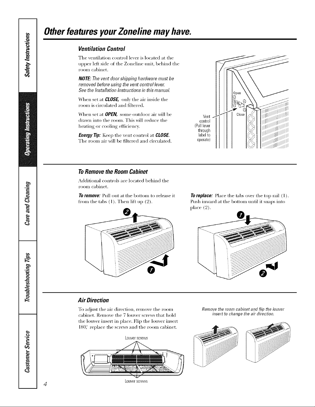
Ventilation Control
The xentilation control lexer is located at the
upper left side of the Zoneline unit, behind the
I'OOIll cabinet,
NOTE:Thevent doorshippinghardwaremustbe
removedbeforeusingthe ventcontrollever.
See theInstallationInstructionsinthismanual.
X,_q_en set at CLOSE, OlflV the air inside the
room is circulated and filtered.
_,_q_en set at OPEN, some outdoor air will be
drawn into the room, This will reduce the
heating or cooling efficiency,
Eaergy Tip: Keep the vent control at CLOSE.
The room air will be filtered and circulated,
ToRemovethe RoomCabinet
Additional controls are located behind the
I'OOIll cabinet,
Te remeve: Pull out at the bottom to release it
fl'om the tabs (1). Then lift up (2).
Vent
control
(Pulllever
through
labelto
operate)
To replace: Place the tabs o_er the top rail ( l ).
Push imvard at the bottom tmtil it snaps into
place (2).
Air Direction
To a(!iust the air direction, remove the room
cabinet. Renlove the 7 louver screws that hold
the louver insert in place. Flip the louver insert
180_ replace the screws and the room cabinet.
Louverscrews
4 Louverscrews
Removethe room cabinet and flip the louver
insert to change the air direction.
Page 5
Auxiliary Controls onyourZoneline. .cEAp ,ia,oos.oom
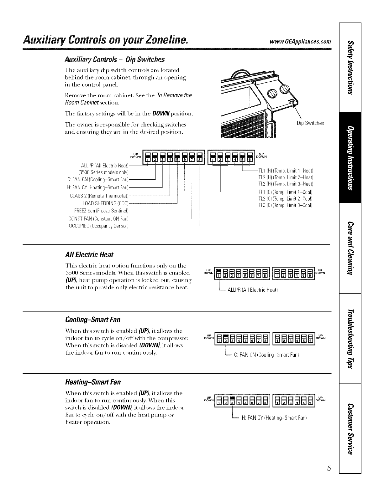
Auxiliary Controls- Dip Switches
The au_liary dip switch controls are located
behind the room cabinet, through an opening
in the control panel.
Remove the room cabinet. See the ToRemovethe
RoomCabinetsection,
The ti_ctox) settings will be in the DOWNposition.
The owner is responsible for checking switches
and ensuring the) are in the desired position.
DipSwitches
ALLFR(All Electric Heat)--
(3500Series models only)
C:FAN CN(Cooling-Smart Fan)
H:FAN CY(Heating-Smart Fan)
CLASS2 (RemoteThermostat)
LOADSHEDDING(CDC)
FREEZSen(FreezeSentinel)
CONSTFAN(Constant ON Fan)
OCCUPIED(OccupancySensor)
All ElectricHeat
This electric heat option flmcfions only on the
3500 Series models. X,_hen this switch is enabled
(UP), heat ptunp operation is locked out, causin,*,
the unit to provide only electric resistance heat.
Cooling-Smart Fan
_._]_en this switch is enabled (UP), it allows the
indoor lira to cycle on/off with the compressor
_._]_en this switch is disabled (DOWN),it allows
the indoor lira to run continuously.
J_og_N
TL2(H)(Temp.Limit 2-Heat)
T '_[_--TL1 (H)(Temp.Limit 1-Heat)
TL3(H)(Temp.Limit 3-Heat)
TL1(C)(Temp.Limit 1-Cool)
TL2(C)(Temp.Limit 2-Cool)
TL3(C)(Temp.Limit 3-Cool)
°°"'EmBBBBBBB][BBBBBB]° "
L ALLI_R(All Electric Heat)
oo : aaaaBailaaaaaaloo':
L C: FAN CN (Cooling-Smart Fan)
Heating-Smart Fan
\,_l_en this switch is enabled (UP), it allows the
indoor tim to run confinuousl); When this
switch is disabled (DOWN),it allows the indoor
lira to cycle on/off with the heat pump or
heater oper;ition.
° :'[BBCBBBBB]IBBBBBBI
L H: FANCY(Heating-Smart Fan)
Page 6
Auxi/iaq controlsonyourZoneline.
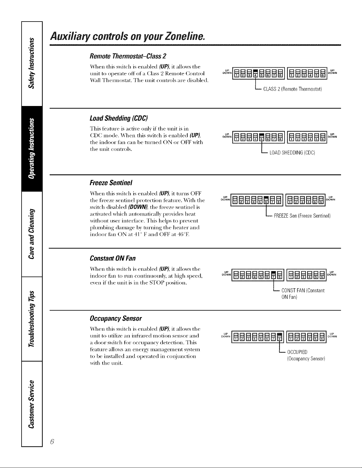
Remote Thermostat-Class 2
_4q_en this switch is enabled (UP), it allows the
unit to operate off of a Class 2 Remote Control
_4*all Them_ostat. The trait controls are disabled.
LoadShedding(CDC)
This teatm'e is active only if the trait is in
CDC mode. When this switch is enabled (UP),
the indoor Lm can be turned ON or OFF with
the Imit controls.
FreezeSentinel
\41_en this switch is enabled (UP), it turns OFF
the freeze sentinel protection teatm'e. _\]th the
switch disabled (DOWN), the fl'eeze sentinel is
acti\med which automatically provides heat
without user intet_tilce. This helps to prevent
plumbing damage by tm'ning the heater and
indoor Jim ON at 41° F and OFF at 46°E
°_IBBB_,BBBBIIBBBBBBI°_
b CLASS2(RemoteThermostat)
°o'-'°IBBBBaB ]IBBBBBB]°o°-'°
L LOADSHEDDING(CDC)
°°"'IBBBBB BBIIBBBBBB]°o""
L FREEZESen(FreezeSentinel)
Constant ON Fan
X&q_enthis switch is enabled (UP), it allows the
indoor tim to mn continuously, at high speed,
exert if the trait is in the STOP position.
Occupancy Sensor
_,_l_en this switch is enabled (UP), it allows the
Imit to utilize an infi'ared motion sensor and
a door switch fin" occupancy detection. This
teatm'e allo_vs an energai management system
to be installed and operated in coqim_ction
with the tmit.
°_°IBBBBBB_,BI[BBBBBB°_"°
b DONST FAN(Constant
ON Fan)
0o_,BBBBBBB@J[BBBBBB °_°
L OCCUPIED
(OccupancySensor)
Page 7
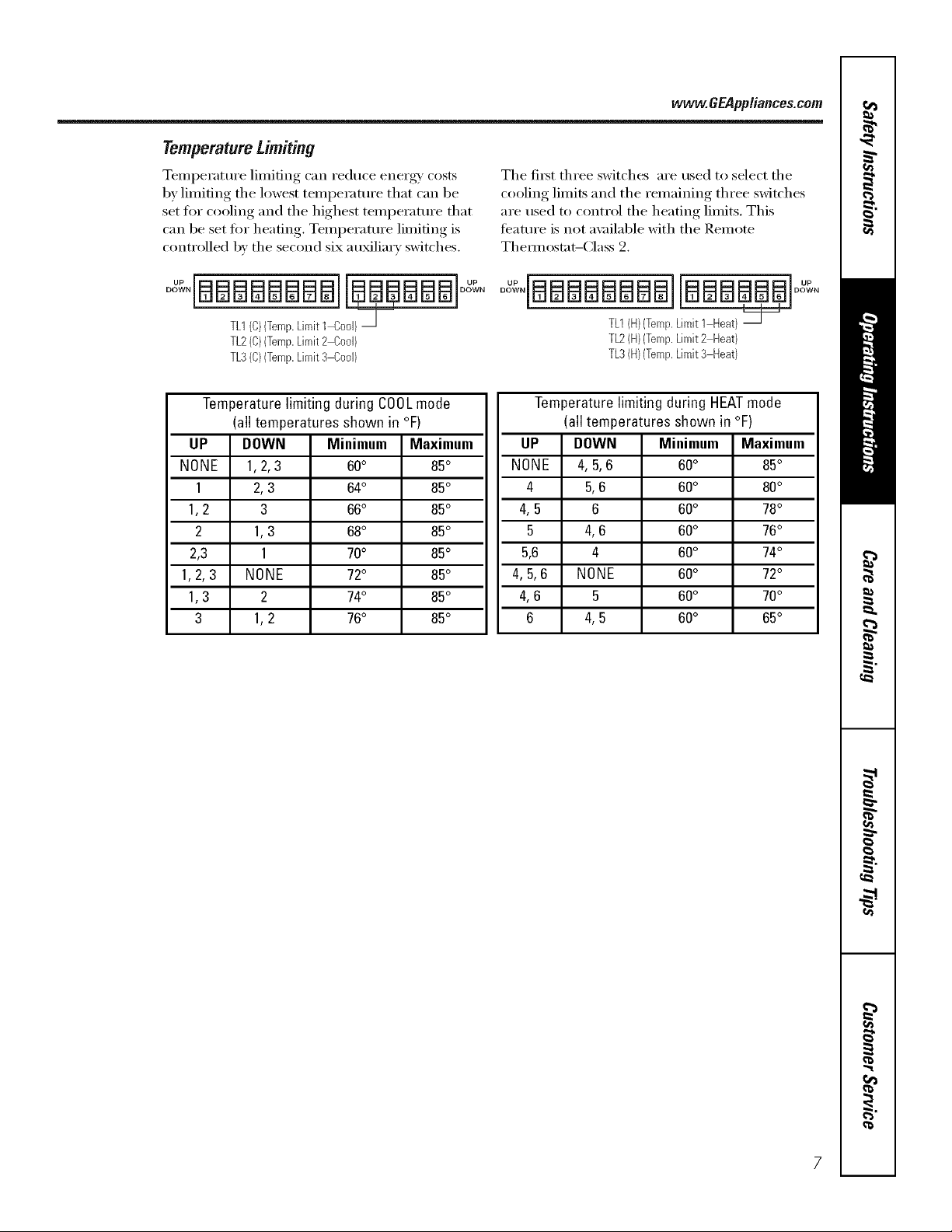
Temperature Limiting
Temperature limiting can reduce enex%_' costs
by limiting the lowest temperature that can be
set fl)r cooling and the highest temperature that
can be set fin" heating, Temperature limiting is
controlled by the second six au_liarv switches,
TL1(C)(Temp.Limit1 Cool)_
TL2(C)(Temp.Limit2 Cool)
TL3(C)(Temp.Limit3 Cool)
www.GEPppliances.com
The fit_t three switches are used to select the
cooling limits and the remaining three switches
are used to control the heating limits, This
teature is not a\_filal)le with the Remote
Them_ostat-Class 2.
o .iaBaaaaaailaaBa a]oo .
TL1(H)(Temp.Limit 1 Heat)
TL2(H)(Temp.Limit2 Heat)
TL3(H)(Temp.Limit3 Heat)
Temperature limiting during COOLmode
(all temperatures shown in °F)
UP DOWN Minimum Maximum
NONE 1,2, 3 60° 85°
1 2,3 64° 85°
1,2 3 66° 85°
2 1,3 68° 85°
2,3 1 70° 85°
1,2,3 NONE 72° 85°
1,3 2 74° 85°
3 1,2 76° 85°
Temperature limiting during HEATmode
(all temperatures shown in °F)
UP DOWN Minimum Maximum
NONE 4, 5,6 60° 85°
4 5,6 60° 80°
4,5 6 60° 78°
5 4,6 60° 76°
5,6 4 60° 74°
4,5,6 NONE 60° 72°
4,6 5 60° 70°
6 4,5 60° 65°
Page 8
Auxiliary controlsonyourZoneline.
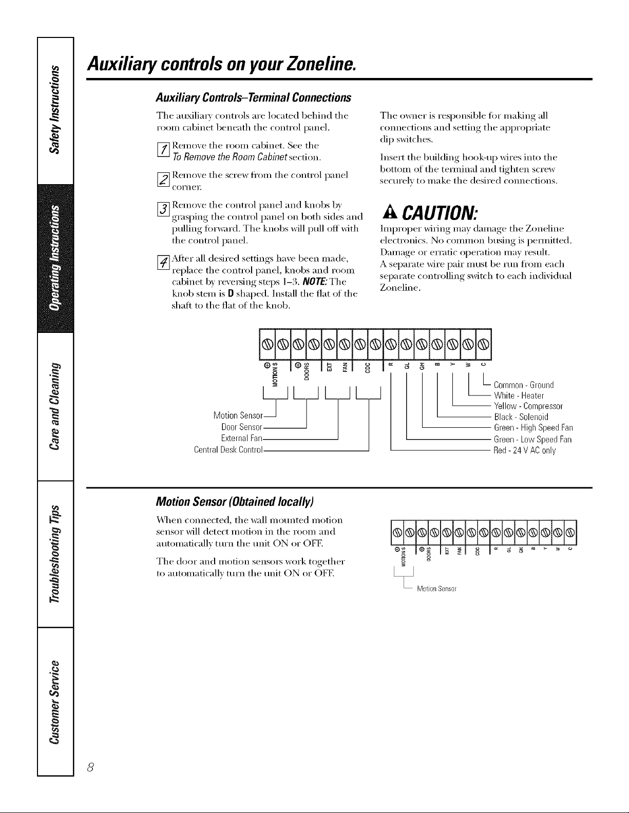
Auxiliary Controls-TerminalConnections
Tile ml_li_' cont_'ols _'e loc_ted behind tile
_'oom cabinet bene_th the cont_'ol p_mel.
_] Remo_,e the _'oom c_binet. See the
ToRemovethe RoomCabinetsection.
[_gem o_e the sc_'ew ti'om the c'ont_'ol p_nel
Coi'nei;
The owne_" is _'esponsible fi_" m_king _11
com_ections _md setting tile _l)l)rOl)_i_te
dip switches.
lnse_'t tile building hook-/_p wi_'es into tile
bottom of the teH_/in_l _md tighten sct'ew
sectu'elv to m_ke tile desi_'ed com_ecfions.
[_] Remoxe tile cont_'ol p_mel _md knobs b)'
grasping the cont_'ol pm_el on both sides _md
pulling fi)_'w;_'d. The knobs will pull off with
the cont_'ol p_mel.
[_Mte_" _ll desi_'ed settings l/_ve been m_de,
_'epl_ce tile cont_'ol pm_el, knobs m_d _'oom
cabinet b)' _'e\'e_ing steps 1-3. NOTEJThe
knob stem is O sh_ped. Inst:_ll the fl_t _ff the
slip,it to the fl_t of the knob.
og
g g
o
Door Sensor
MotionSensor_J L_ L L_
External Fan
Central Desk Control
Motion Sensor(Obtained locally)
_,_q/en com_ecte(1, tile w_ll motmted motion
sensor" will detect motion in the _'oom _md
mm_m_fic_llv ttu'n tile trait ON o_" OFE
Tile (loot [lIl(1 i/lotion sensoi3 wol'k togethei"
to m_tom_atic_allv ttu'n tile trait ON or OFE
CAUTION:
Improper" M_ing m_y clam_ge tile Zoneline
elect_'onics. No common busing is pem_itted.
D_m/_ge o_"er_'_tic oi)e_'_fion m_y _'esult.
A sei)__m wi_'e i)_i_"i/ltlst be mn fl'om e_cl/
sei)_'_te cont,'oiling swit('h to e_cl/in(lividt_l
Zoneline.
L-common- Ground
White - Heater
-- Yellow- Compressor
Black- Solenoid
Green - High Speed Fan
Green- Low Speed Fan
Red- 24 V AConly
@_@@@@@@@@@@@@---1
eo__ le_ I_ _1 o_ i _ _ _ ....
Motion Sensor
8
Page 9
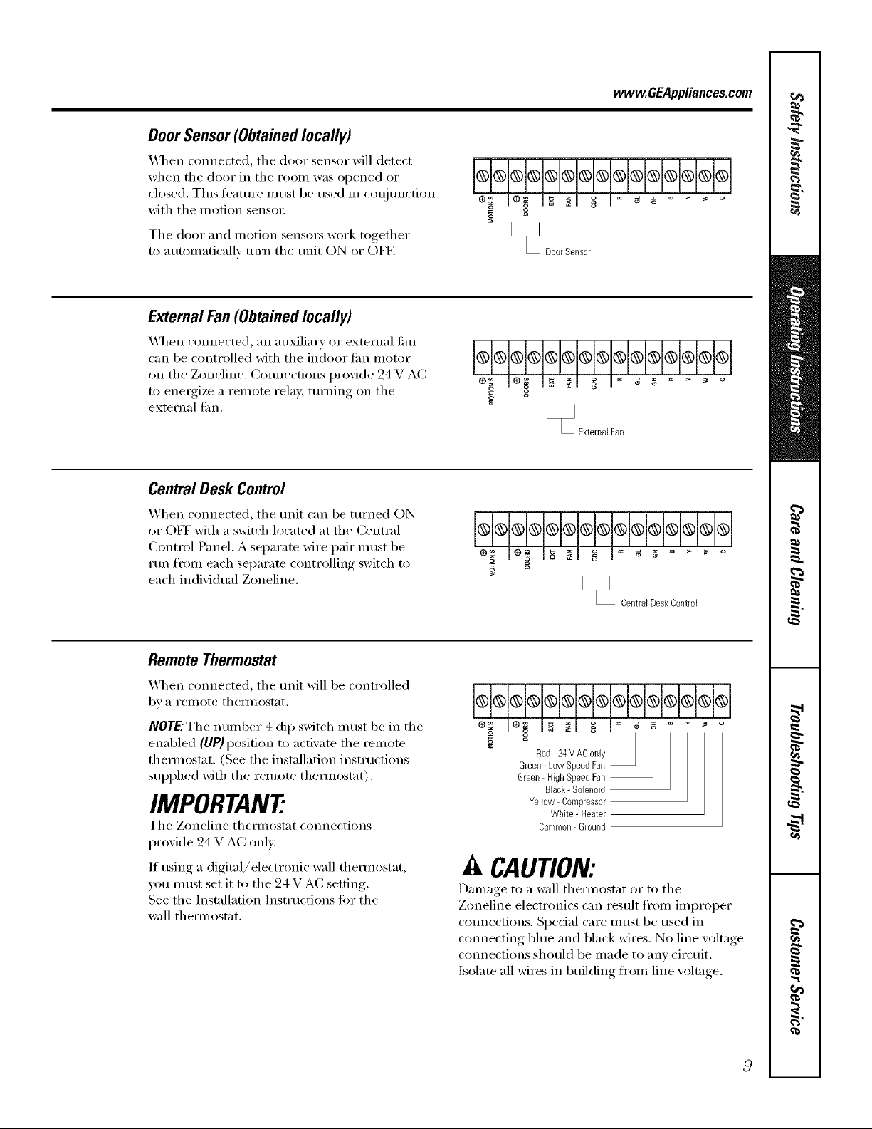
Door Sensor (Obtained locally)
_]/en connected, tile door sensor will detect
when tile door in tile i'OOill W_lS opened or
closed. This teatm'e must be used in coI_junction
with tile motion senso_:
The door and motion sensm_ work together
to automaticallx mrn tile refit ON or OFE
External Fan(Obtainedlocally)
_41/en connected, an auxiliary or external tim
can be controlled with tile indoor tim motor
on the Zoneline, Connections provide 94 V AC
to energize a remote relay, turning on tile
external tim.
Central Desk Control
vvww.GEAppliances.com
@@@@@@@@@@@@@@
2
" DoorSensor
g
[_ ExternalFan
X_l/en com_ected, tile refit can be turned ON
or OFF with a switch located at the Central
Control Panel. A separate wire pair must be
run fl'om each separate controlling switch to
each individual Zoneline.
Remote Thermostat
X_q/en connected, tile refit _fill be controlled
bv a i'elllote thelillostat.
NOTE'The number 4 dip switch must be in tile
enabled (liP)position to acti\'ate tile relnote
them_ostat, (See the installation instructions
supplied with the remote them_ostat),
IMPORTANT
Tile Zoneline them_ostat connections
provide 24 V AC onE'.
If using a digital/electronic wall them_ostat,
you must set it to tile 24 V AC setting.
See tile Installation Instructions for tile
wall them_ostat.
@
[_ CentralDeskControl
Red 24VAC only
Green- Low SpeedFan
Green High SpeedFan
Black- Solenoid
Yellow Compressor
White - Heater
Caermon Ground
A CAUTION:
Damage to a wall them/ostat or to tile
Zoneline electronics can result fl'om improper
connections. Special care must be used in
cmmecting blue and black wires. No line w)ltage
connections should be made to any circuit.
Isolate all wires in building fl'om line w)ltage.
Page 10

Careand cleaning.
Room Cabinet and Case
Turn the Zoneline oiI and disconnect the
power supply:
OutdoorCoils
Tile coils on tile outdoor side of tile Zoneline
should be checked regularly. If the)' are clogged
with dirt or soot, they may be protessionally
steaIll cleaned, a service a\_filable through your
(;E se_Mce outlet. You will need to remove the
trait to inspect the coils because the dirt
build-up occm_ on tile inside.
To clean, use water and a mild detergent.
Do not use bleach or abrasives. Some commerdal
cleane_ may damage the plastic parts.
Coils
Grille
Clean the outside coils regularly.
Base Pan
In some installations, dirt or other debris may be
blown into the unit fl'om the outside and settle in
tile base pan (tile bottom of tile unit).
In sore e a teas of th e U nited States a "jell-like"
substance may be seen in tile base pan.
Check it periodically and clean, if necessary.
10
Page 11

Tomaintain optimum performance, clean the filters at least every30 days.
Air Filters
D_
To remove the air filters:
vvww.GEAppliances.com
2Airfilters
Pullup
Dirty filter--Needs cleanflTg Clogged filter--Greatly
reduces cooling, heating
andairflow.
TurntheZoneline offbeforecleaning.
The most importnnt thing you can do to
maintain the Zoneline is to clean the filter
at least every 30 days. Clogged filte_ reduce
cooling, heating and air flow.
Keeping these filters clean will:
• Decrease cost of operation.
• Save energy:
• Prevent clogged heat exchanger coils.
• Reduce the risk of prematm'e component
fifilm'e.
To clean the air filters:
• Vacumn off the heavv soil.
• Rtm water through the filte_.
• D_T thoroughly befiwe replacing.
Toreplace the air filters:
Pushdown
A CAUTION:oo.otoperatethe
Zoneline without the filters in place, ff a filter
becomes torn or damaged it should be replaced
immediately.
Operating without the filte_ in place or with
damaged filte_ will allow dirt and dust to reach
the in-door coil and reduce the cooling, heating,
airflow and efficiency of the unit.
Replacement filte_ are available fl'om vom"
salesperson, GE deale_; GE Service and Parts
(_enter or authoYized (_ustomer Cai'e '_sei'vicei_.
11
Page 12

Installation
Zoneline Air
Instructions
Conditioners
I Ouestions?Call800.GE.CARES(800.432.2737)orVisitour _bsJte at: www.GEAppliances.com I
BEFORE YOU BEGIN
Read these instructions completely mid carefully.
• IMPORTANT - S.,e_hese
inst_ uctions tin" local inspector's use.
•IMPORTANT - Obse,,e..
governing codes and ordinances.
• Note to Installer _ Be sure to leave these
instructions with the owner.
• Note to Owner _ Keep these instructions tot
fllture reterence.
• Proper installation is the responsibility of the
installer.
" Product failure due to improper installation is not
covered under the _'arrantv.
TOOLS YOU WILL NEED
Phillipsscrewdriver
IMPORTANT ELECTRICAL
SAFETY-READ CAREFULLY
_k CAUTION:
• Follow the National Electrical Code (NEC) or local
codes and ordinances.
• For personal safety, this Zoneline must be properly
grounded.
• Protective devices (fuses or circuit breakers)
acceptable for Zoneline installations axe specified
on the nameplate of each refit.
• Do not use an extension cord with this unit.
Aluminum building wiring may present special
problems--consult a qualified electrician.
When the unit is in the STOP position there is still
voltage to the electrical controls.
Discmmect the power to the refit before
servicing by:
1 Removing the power cord (if it has one) from
the wall receptacle.
OR
2 Removing the branch circuit fuses or turning
the circuit breakers off at the panel.
ZONELINE COMPONENTS
Exteriorgrille/IouveP*J
Wallcase_f--}
ShippedwiththeZonelineunit
Checkthe "EssentialElements"listontheunit
rn cabinet*
--- Zonelineunit
12
Page 13

Installation Instructions
REPLACING AN EXISTING UNIT?
Checkthe "Essential
Elements"labelfor
importantinformation.
Use the correct wall case
This unit is designed to be installed in a GE plastic or
insulated metal wall case. This minimizes condensation
fl'om fimning on the room side ot the case.
If the cmTent wall case is not insulated, you can reduce
the possibility of condensation tomfing by inst;flling
insulation kit ]_Kg01 I,, available where you pro'chased
the mfit.
Use the correct outdoor grille
You should use the outdoor grilles shown on the
"Essential Elements" label on the top of the unit.
• If an existing grille is not replaced, capacit)' and
efficiency will be reduced and the refit may tifil to
operam propedy or fifil prematm'ely: A deflector kit,
]_&K40, nlay be used with grilles that were not
designed t0r )'ore" new GE Zonelines. The RAK40
contains air deflectms and gaskets that mount to the
refit to direct the hot exhaust air away fl'om the air
intake to allow the refit to flmction properly. The
grille must have a 65% minimmn fl'ee area.
• Any vertical deflecto_ in the existing rear grille should
be rellloved to decrease condenser air recirctllation
which can cause the refit to "short-cycle" and lead
to pi'ei/lattli'e COli/ponent filihu'e.
Replacing a ducted unit
New ducted installation:
If this refit is to be installed in a new ducted application
using a duct adapter kit, the kit must be installed befi)re
the refit is placed in the wall case. The installation
instructions are packed with the kit.
plate
Existhag ducted installation:
Replacement of an existing ducted refit may require
difli_rent components. Request this inl0mmtion ti'om
w)ur sales representative.
• Replacing 230/208 volt milts:
See page 14.
• Replach_g 265 volt milts:
See pages 15 and 16.
13
Page 14

Installation Instructions
HOW TO CONNECT
1 I_emove the room cabinet.
2 Connect to electrical power,
3 See the special instructions below fi)r ai)plicable
supply voltages.
4 Reinstall the r()om cabinet.
230/208 VOLT
ELECTRICAL SUPPLY
All wiring, including installation of the receptacle,
must be in accordance with the NEC and local codes,
ordinances and regulations.
This trait is equipped with a line cord ti)r ai)i)ropriate
amperage wall receptacle, See below,
© © @
Tandem Perpendicular Large Tandem
15Amp. 20 Amp. 30Amp.
230/208 xolt models ma) be installed using one of
the following electrical subbases:
Branch Circuit and
Unit Amperage Bating
15/20
3O
Electrical subbases provide a flexible enclosm'e fi)r
direct connection or enclosed receptacles.
The instructions provided with the selected subbase
kit must be careflfllv fi)llowed. It is the resl)onsibili V
of the instnller to ensm'e the connection ot
components is done in accordance with these
instructions and all electrical codes.
Proper GE
Subbase Kit
I,LM,L204D20
]L_K204D30
230/208 volt recepta cle configuration.
direct connection.
I Order Kit ]L_K4002A for 230/208 _olt
I
14
Page 15

Installation Instructions
265 VOLT ELECTRICAL SUPPLY
A WARNING:
Connection of this 265 V AC product to a branch
circuit MUST be done by direct cmmection in
accordance with the National Electric Code.
Plugging this trait into a building motmted
exposed receptacle is not pemfitted by code.
These models must be installed using one of the
following methods:
A Electrical subbase kits are a\_filable to ixxwide a
flexible enclosm'e fin" direct com]ection.
Branch Circuit and Proper GE
UnitAmperage Rating Subbase Kit
15 1_I(204E 15
20 ILMq204E20
30 ILMq204E30
The instructions provided with the selected subbase
kit must be careflflk fi)llowed. It is the responsibility
ot the installer to ensure the connection of
components is done in accordance with these
instructions and all electrical codes.
[] REMOVE JUNCTION BOX
1 Remoxe the junction box coxer b) taking out the
froilt two screws.
Remove thejm]ction box by taking out the top
and bottom rear screws. Note how the tabs on
the lower left side of thejm]ction box serve to
hold the side in place. This will hel I) when the
box is being reinstalled. The cord will be coiled
up inside thejtmction box.
Junction
boxcover
J
Junction box
B For direct cmmecfion to branch circuit wiring inside
the providedjm]ction box without using a subbase
kit, cut the cord, strip the wire ends and connect
as tbll_>_vs.
[] CUT AND STRIP THE CORDSET
1 Measm'e 6" down the cord ti'om the strain reliet
securing the cord to the trait and cut the cord
through at this point.
2 Carefully split the cord insulation at the center
t0r 2" so as to separate into three insulated wires.
Be careflfl not to cut through the center green
grotmd wire insulation.
3 Strip 3/4" of the insulation away at the end
of each of the three wires (I,1, Neutral and
(;rotmd). The Neutral wire is identified by
molded rib along its entire length. The 1,1
(Hot) wire insulation is smooth.
.... .ULL.(moldedrib)_ _ _E-
blratn "--'J'_fL_l _ I I
re "ef _ -- =-'_,_'iGr°und. wire
Neutralwire_ x 3/4"
_.._._--.._ "-'_/-- El wtre
I_<_2_> " (smooth)
15
Page 16

Installation Instructions
265 VOLT ELECTRICAL SUPPLY
disconnect inside the junction box.
I NOTE: (-)rder Kit RAK4002C_4 to enable a quick
[] ATTACH CONDUIT
1 Use the round knockout at the botton_ of the
junction box to attach conduit coming fl'om the
branch circuit. Remove the knockout, attach the
conduit and bring wires into the junction box.
I,eave 6" of wire ti'ee at the end of the conduit
to allow connections to be made.
[] MAKE WIRING CONNECTIONS
I
1 Make all wire connections by using appropriate
UL-lismd electrical connecto_ and mchniques
(black to black, white to white and green to green).
2 Careflfllv tuck all wires and connections back inside
thejtmcfion box. Be sure there are no loose
connections oi" sti'av uninsulated wires exposed.
3 Place the junction box cover in place. Replace the
two scre_vs removed earlier and tighten securely:
4 Discard the unused portion ot the plug and
the cordset.
2 If a fllse and fllseholder are to be used, the knockout
at the top of the box is for mounting a Buss
Fuseholde_: Be sure the fl,se and fllseholder are of the
same rating as the branch drcuit. I,eadwires at the
fllse can be either soldered in place or attached using
UIAisted 1/4" female (receptacle) crimp connecto_.
[] REINSTALL JUNCTION BOX
• Reinstall the junction box by engaging the left tabs
on the lower _ight ti_ce of the unit, aligning the
screw holes at the top and bottom and d6ving the
two screws until secure. Be sure that all wire leads
are inside the box and not pinched between the box
and the unit.
The identified (ribbed) Neutral wire of the cordset
MUST be connected to the white Neutral wire of
the branch circuit. The green insulated gromM wire
ti'om the unit MUST be connected to the branch
circuit ground wire.
16
Page 17

Installation instructions
INSTALLING THE ZONELINE
[] iNSTALL THE WALL CASE AND
EXTERIOR GRILLE
Tile I_B71 series or I_B77 wall case must be
properly installed per instructions packed with
tile case,
* P.emo\ e tile corrugated stiftener and tile outdoor
protective panel. Llse tile slit ill tile otltdooF panel
as a handhold and push out.
Pro
panel
Stiffenel
* Install the exterior grille from the room side
folio*ring instructions packed *dth tile grill.
Insulated Wall Case
This trait is designed to be installed in a GE plastic
or an instflated steel wall case. This minimizes
condensation fi'Ol// ik)ll//ing oil tile I'OOI// side of
tile case.
Tile ILkB7I series wall cases are insulated. Insulation
ldt IgM{.901 I, is a_:dlable fiw use with lgkg77 o*
existing uninsulated wall cases when needed.
NOTE: For installation with a subbase or duct adaptec
see tile instructions packed with those ldts.
[] PREPARE THE ROOM CABINET
• Careflflly remo_e shippii_g tape, if there is an,v, ti'Oln
tile i'OOill cabinet and lent dooE
Sh
tape
• Relnoxe tile shippii_g screw/clamp fl'Oln tile top of
tile lent dooi; if present.
Removeshipping
screwandclamp
if present
• Remoxe tile room cabinet by pulling it out at tile
bottom to release it (1), then lift it up to clear tile
rail ahmg the trait top (2).
@
17
Page 18

Installation Instructions
[] iNSTALL THE UNiT iNTO THE
WALL CASE
Slide the unit into the wall case and secure with ibm"
scre_s through the unit flange holes.
[] REPLACE THE ROOM CABINET
Reinstall the roon_ cabinet by hooking the top oxer
the rail ahmg the unit top ( l ), then I)ushing, it in at
the bottom (2).
18
Page 19

Installation Instructions
OPTIONAL- DRAIN KIT INSTALLATION
Dry Air 2500 Series models axe designed to improve dehumidification by 25%. Since more moisture will be removed from
the air, there is a greater possibility that water will drip from the wall case than with a stm_dard unit. To prevent this water
from dripping onto external building walls, we recommend the use of RADIO Drain Kit.
External Drain
See the Installation ]nst_twtions
in the RADIO kit.
Alternate:
6"long, 1/2" O.D. straight
coppertube
/
Internal Drain
See the Installation ]nstrtwtions
in the ILA_D 10 kit
Squaredrainholes
"_ "_ _l-_ Type"A" screwformetalcaseor
1/2" O.D.draintube _ _[ T._
Neoprenespongegasket t
Steelmountingplate
Type"B"screwformoldedcase
Squaredrainholes
Neoprenespongegasket /
Steelmountingplate
"_ "_ _-_Type "A" screwfor metalcaseor
Type"B"screwformoldedcase
19
Page 20

Before YouCallForService...
TrOubleshooting tips
Save time and money! Review the charts on the following
ages first and you may not need to call for service.
Problem Possible Causes What To Do
Zoneline does The refit is * Make sure the Zoneline plug is pushed completely
not start unplugged, into the outlet.
The fuse is blown/drcuit * (_he('k the house fllse/circuit breaker box and replace
breaker is tripped, the fllse or reset the breaker:
The refit is waiting for • This is nomml. The Zoneline will start again after
the compressor overload it resets.
protector to reset.
Power failure.
• If power tailure occm_, set the mode control to STOP.
\_]_en power is restored, set the mode control to the
desired setting.
• There is a protective time delay (up to 3 minutes) to
prevent tripping of the compressor ove_toad. For this
reason, the unit may not start nomml heating or cooling
tot 3 minums after it is turned back on.
Zoneline does not cool Indoor airflow • Make sure there are no curtains, blinds or flu'niture
orheatas it should is restricted, blocking the ti'ont oI the Zoneline.
Outdoor airflow is
restricted or recireulated.
The temp control may • Turn the control to a lower or higher settin ,
not be set high enough. NOTE:Thetemperaturellmitermaybe llmitlW thetemperaturerange.
The air Fdter is dirty. • Clean the filter at least every 30 da):s.
The room may have • \,_]_en the Zoneline is fi_t turned on vou need to
been hot or cold. allow [iu/e tor the I'OOUl to COO1 down oi" _v;IY/l/ Ill).
Outdoor air is • Set the vent control to the CLOSE position.
entering the room,
Burning odoratthe start Dust is on the surface • This can cause a "burning" odor at the beginning of
ofheating operation of the heating element, the heating operation. This odor should quickly lade.
The air is notalwags The heat pump is not • This is nomml. The heat i)ump will produce w:mn air
cool or hot during producing hot air. but not as hot as air produced when the highe>cost
operation electric heat is used.
The fan switch may be • This causes the fan to blow room teml)erature air
set at continuous fan even when the compressor or heater cvcles off.
• Make sure the rear grille is not restricted. This can cause
the unit to cycle off due to the compressor overload.
• Outdoor grille must have a minimum ot 65% fl'ee area.
Non-GE grilles may be too restrictive fi)r proper
pe_timnance. Consult your salesperson fiw assistance.
See the Operating Instructions section.
The continuous air movement provides better
overall temperattu'e control.
Thea# doesnotfeel
warm enoughduring
heating operation
2O
The heat pump alone
produces air that feels
cooler than desired.
• Use the Electric Heat Option. This turns off the
heat pure I) and wam_s with electric heat only.
NOTE: Use of this option will result in increased energy
consumption.
Page 21

Thingsthatare normal www.GEAppliances.com
Normal Operating Sounds
You may hear a pinging noise caused by water being
pI N G! POP'
picked up and thrown against the condenser on
rainy days or when the lmmidiQ' is high. This design
ti_attu'e helps remove moisture and improve
efficiency.
"CLICK"
DRIP
6
WHIR!
You may hear reims click when the controls cxcle
on and off or are a(!justed to change the room
temperature.
X,%_terwill collect in the base pan during high
humidit_ or on rainy dins. The water may oxerflow
and drip fl'om the outdoor side of the unit.
The indoor lira runs continuously when the unit is
operating in the cooling mode, unless the thn switch
behind the room cabinet is set at thn cycle (up).
This will cause the tim to cycle on and off with the
COIIII)I'eSsoY. rOll Ill}IV }IIso hear a tim noise stop
and start.
You may notice a t_'w minutes delay in starting if you
try to restart the Zoneline too soon atter turning it
ott or if you at!just the them/ostat right after the
compressor has shut off. This is due to a built-in
restart protect())" tot the compressor that causes
a S-minute delay.
The comi)ressor shuts off during, the defl'ost cycle.
Full resistance heat comes on dufino the deti'ost
cycle to II/}liIl[_liIl I'OOIIl COIII][()I'[.
COMPRESSOR
PROTECTION
To protect the compressor and prevent short
c)'cling, the unit is designed to run lot a minimum
of 3 minutes, atter the compressor starts at any
them/ostat setting.
21
Page 22

cs_
€_
cs_
NOteS_
€_
r_
22
Page 23

Notes,
23
C_
Page 24

cs_
€_
cs_
NOteS_
€_
r_
24
Page 25

Please place in envelope and mail to:
General Electric Company
Warranty Registration Department
P.O. Box 32150
Louisville, KY 40232-2150
25
Page 26

Consumer Product Ownership Registration
Deal Customer:
Thank you for purchasing our product and thank you for placing your confidence in us.
VFe are proud to ha_e you as a customer'.
Follow these three steps to protect your new appliance investment:
Complete and llla_
your Consumer
Product Ownership
Registration today.
t]a_c the pca(c el
mind of knowing we
C_tI/ CO11taCt VO/I ill
th( unlikely (x<nt of
a sa/;vtv modi/ication.
Mlcr mailing the
registration below,
store this dOC[ll//(ql[
in a satb place. It
contains intbrmation
you will need should
you require scrvi(c.
Our scrvi( c nmnbcr is
800.(;E.CA I,II_;S
(800.432.2737).
Model Number Serial Number
I I I I I I
Important: If you did not get a registration card with your
product, detach and return the form below to
ensure that your product is registered, or register
online at www.GEAppliances.com.
Consumer Product Ownership Registration
[_C_t(t VO/IF Owncr's
Mamml carefully.
It will hel t) you
ot)cram your new
at)t)liamc t)rot)crly.
, I
._ Cut h(r(
Model Number Serial Number
MI: [ Ms. M*>,.[ Mix_,
Fir_,l I I L_Sll
Name I I I I I I I I I Nain(! I I I I I I I I I I I I
Sl 1-( (!1 I
Addr( ss I I I I I I I I I I I I I I I I I I I I I I I I
A,_.#I, , , , , , , I E-lnailAddress*
Zip I
1)ue Pla(ed
Monlh
* F'l( asc F' _ v ( ( y 1 - (- a a( ( -css to r( ceiv(, via (-mail, discounts, special offers mM other importam
(ommuni(ations h-Oln GE Applian((s ((;1L",.).
Ch((k h(r( if you do not v,ant to re(( ire (olnmuni(ations from (;EA's ( arefully sele(ted parm( rs.
_.m,..-I,, I-I,, I-I
0
GEAppliances
General E/ectric Compally
Looisville, Kentocky
w_GEAppliances,com
26
I
I
Page 27

Zoneline Warranty.
_ II warranty service provided by our Factory Service Centers,
or an authorized Customer Care®technician. Toschedule service,
on-line, 24 hours a day, vis# us at www.GEAppfiances.com,
or call 800.GE.CARES(800.432.2737).For service in Canada,
call 1.800.361.3400.
For The Period Of."
OneYear
Fromthedate of the
originalpurchase
Five Years
Fromthedate of the
originalpurchase
FiveYears
Fromthedate of the
originalpurchase
GEWill Replace:
Anypartof the Zoneline which fifils due to a defect in materials or workmanship. During this
full one-year warranty, GE will also provide, free of charge, all labor and on-site service to
replace the def_'cti\'e part.
Any part ofthe sealed refrigerating system (the compressox; condensex; evaporator and all
connecting tubing) which fifils due to a (lefe('t in materials or workmanship, L)urh_g this
full five-year sealed refrigerating system warranty, GE will also proxide, free ofcharge, all labor
and on-site service to replace the (lete('ti\'e part.
For the second through the fifth yearfl.om the date of original purchase, (;EMll replace
certainpartsthat tifil (lue to a def_'ct in materials or worlunanship. Parts covered are tim
mot(n_, switches, them/ostats, heate_; heater protecto_, compressor overload, solenoids,
drcuit boards, au_liary controls, themfisto_5, fl'ost controls, ]CR i)ump, capacito_,
w_ristoxs and indoor blower bearing. During this limited four-yearpartswarranty,you will be
responsil)le fin" any labor or on-site service costs.
What GE Will Not Cover:
Staple your receipt here.
Proofof the original purchase
date is needed to obtain service
under the warrantg
• Service trips to your site to teach you how to use the
product.
• Improper installation.
If you have an h_stadlation problem, or if the air
conditioner is of hnproper cooling capacity for the
intended use, contact your dealer or installer. You are
responsible for providing adeqwate electrical
comlecth_g facilities.
• In commercial locations, labor necessary to move the
trait to a location where it is accessible for service by an
hldJvidual teclulicim_.
• Failure or damage resulting from corrosion due to
hlstaJlation in ml enviromnent containing corrosive
chemicals.
• Replacement of fuses or resetting of circuit breakers.
• Failure of the product resulting from modifications to
the product or due to tmreasonable use including
failure to provide reasonable m_d necessary
iYl_dntena_lce.
• Failure or dmnage resulting from corrosion due to
hlstaJlafion in a coastal enviromnent, except for models
treated with special factory-applied m_ti-corrosion
protection as designated in the model number.
• Damage to product caused by improper power supply
voltage, accident, rinse, floods or acts of God.
• Incidental or consequential dmnage to personal
property caused by possible defects with this air
conditioner.
This warranty is extended to the original purchaser and any succeeding owner for products purchased for use
within the USA and Canada. In Alaska, the warranty excludes the cost of shipping or service calls to your site.
Some states or provinces do not allow the exclusion or limitation of incidental or consequential damages. This
warranty gives you specific legal rights, and you may also have other rights which vary from state to state or
province to province. Toknow what your legal rights are, consult your local, state or provincial consumer
affairs office or your state's Attorney General.
Warrantor: General Electric Company. Louisville, KY 40225
27
Page 28

ConsumerSupport.
Ha_e a question or need assist;race with your appliance? Tr_ the GE Appliances _4'ebsite 24 hom_ a day,
l GEAppliancesWebsite vvvvvv.GEAppliances.com
' an_ day of the _ear! For greater con;enience and tipster service, you can now download Owner s Manuals,
order parts, catalogs, or e_en schedule service on-line. You can also "_sk Our Team of Expe_ls ....
} O/lI" qtlestions, and so Ill t/ch Ill ore...
ScheduleService
Expert GE repair se_,ice is only one step awm fl'om your doo_: Get on-line and schedule _our se_,ice at
your, comenience 24 hom_ any day of the year! Or call 800.GE.(_AI/ES (800.432.2737) during nomml
business hom_.
vvvvvv.GEAppliances.com
RealLifeDesignStudio vvvvvv.GEAppliances.com
GE supports tile/Jni\'e_al Design concept--products, se_a'ices and environments that can be used by
people _d all ages, sizes and capabilities. _,\'e recognize tile need to design for a wide range of physical and
mental abilities and impaim_ents. For details of GE's/Jnive_al Design applications, including kitchen
design ideas for people with disabilities, check out Otli" _4'ebsim today. For tile hearing impaired, please call
800.TDD.GEAC (800.833.4322).
PartsandAccessories vvvvvv.GEAppliances.com
Individuals qualified to service their own appliances can have parts or accessories sent directly to their
homes (VISA, MasterCard and Discover cards are accepted). Order on-line toda 5 24 hom_ every day or
by phone at 800.626.2002 during nomml business hom_.
Instructions contained in this manual cover procedures tobe performed by any user. Other servicing generally
should be referred to qualified service personnel Cautionmust be exercised, since improper servicing may cause
unsafe operation.
Contact Us wwvv.GEAppliances.com
If you are not satisfied with tile service you receive ti'om GE, contact us on our _'ebsite with all tile details
including your phone number; or write to: General Manager; Customer Relations
GE Appliances, Appliance Park
I,ouisville, KY 40225
Register your new applim_ce on-lhle--at your convenience! Timel_ product registration will allow for
l RegisterYourAppl&nce vvvvvv.GEAppliances.com
enhanced communication and prompt serxice under tile tem/s of }our warranty, should tile need arise.
You may also mail in tile pre-printed registration card included in tile packing material, or detach and
rise tile timn in this Owner's Manual.
Printed in China
 Loading...