

GE AZ35H07E4DM1, AZ35H07E3DM1, AZ35H07D3DM1, AZ35H07D2DM1 Owner’s Manual
©
www.GEAppfiances.com
Safety Instructions ........... 2
Operating Instructions
Air Direction ................ 4
Auxiliary' Controls .......... 5-9
Controls .................... 3
Vent Control ................ 4
Care and Cleaning
Air Filters .................. ] ]
Base Pan .................. ] 0
Outdoor Coils .............. ] 0
Room Cabinet and Case ...... ] 0
Installation Instructions
Electrical Supply ......... ] 4-16
Installing the Zoneline .... 17, 18
Optional Drain Kit .......... 19
Preparation ................ 12
Replacing an Existing Unit? . . .l 3
Heat/Cool Model 2500
Heat Pum[J Modal _500
©
Troubleshooting Tips ....... 20
Normal Operating Sounds .... 21
Consumer Support
Consumer Support . . .Back Cover
Product Registration ...... 25, 26
*A,_rranty .................. 27
Write the model and serial
numbers here:
®
Model #
Serial #
Find these numbers on a label
behind the room cabinet on the
base pan.
49-7415-2 JR 06-01
IMPORTANTSAFETYINFORMAtiON.
READALLINSTRUCtiONSBEFOREUSING.
A WARNING!
Foryour safe_ the information in this manual must be followed to minimize the risk of fire or
explosion, electric shock, or to pre vent property damage, personal injury, or loss of life.
_\ "_j____SAFETYPRECAUTIONS
_y_ • This Zoneline must be properly
installed in accordance with the
Installation Instructions before it is
used. See the Installation Instructions
in tile back of this manual.
• hnmediately repair or replace all
electric service cords that have become
frayed or otherwise damaged.
• Unplug or disconnect the Zoneline at
tile fllse box or circuit breaker before
making any repairs.
NOTE: ¼:e strongly recommend that any
servicing be performed by a qualified
individual.
READANDFOLLOWTHISSAFETYINFORMAtiONCAREFULLY.
SAVETHESEINSTRUCtiONS
Replacing an existing un#?
For details, see the Installation
Instructions in this manual.
2
Aboutthe controlsonyourZoneline. _.GEA..li..ces.com
LOW
FAN
STOP°° °'_2."
AUTOA _f_ t_ 'A AUTO
HEAT"! I I yCOOL
HIGHAll I I IIA HIGH
HEATw_,. COOL
MODECONTROL
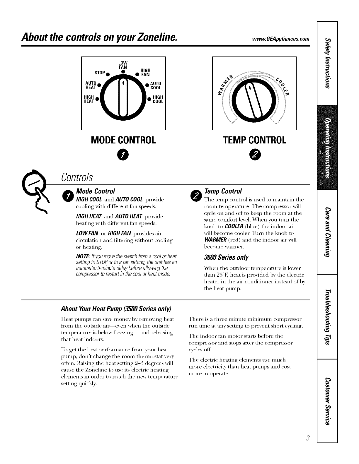
Mode Control
(_ Co_trols
HIGH COOL and AUTO COOL proxide
cooling with different fire speeds.
HIGH HEAT and AUTO HEAT proxide
heating with different tim speeds.
LOWFAN or HIGH FAN provides air
circulation and filtering without cooling
or heating.
NOTE: Ifyoumove theswitch froma coolor heat
setting to STOPor to a fan settlhg the unit has an
automatic3-minute delaybeforea//owlhg the
compressorto restart inthe cool orheat mode.
About YourHeatPump(3500Seriesonly)
Heat pmnps can save money by removing heat
fl'om the outside ai_e\'en when the outside
temperature is below fl'eezing-- and releasing
that heat indom_.
To get the best pex_ommnce flxm_ ):our heat
pump, don't change the room them_ostat ve_y
otten. Raising the heat setting 2-3 degrees will
cause the Zoneline to use its electric heating
elements in order to reach the new temperatm'e
setting quickly:
@
TEMPCONTROL
@
TempControl
@
The temp control is used to maintain the
room temperature, The compressor will
cycle on and off to kee I) the room at the
same comfort level, When w)u tm'n the
knob to COOLER(blue) the indoor air
will become coole_: Tm'n the knob to
WARMER (red) and the indoor air will
become wa iillei:
3500 Series only
_]_en the outdoor temperatm'e is lower
than 25°E heat is provided by the electric
heater in the air con(litioner instead of by
the heat pump.
There is a three miimte minimum compressor
run time at any setting to prevent short cycling.
The indoor tim motor starts befl)re the
COllll)I'essoI" [lIl(l stops atter the coi/ll)i'essoi"
cycles off'.
The electric heating elements use much
more electricity than heat pmnps and cost
illOi'e to operate.
3
OtherfeaturesyourZoneline mayhave.
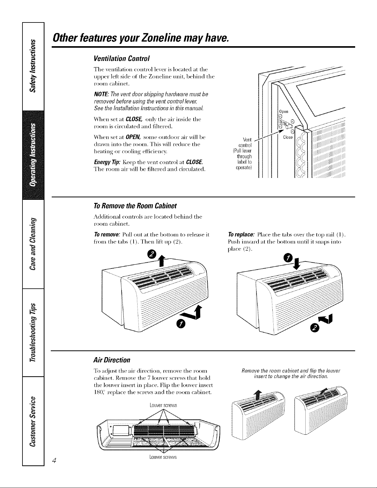
Ventilation Control
The xentilation control lexer is located at the
upper left side of the Zoneline unit, behind the
I'OOIll cabinet,
NOTE:Thevent doorshippinghardwaremustbe
removedbeforeusingthe ventcontrollever.
See theInstallationInstructionsinthismanual.
X,_q_en set at CLOSE, OlflV the air inside the
room is circulated and filtered.
_,_q_en set at OPEN, some outdoor air will be
drawn into the room, This will reduce the
heating or cooling efficiency,
Eaergy Tip: Keep the vent control at CLOSE.
The room air will be filtered and circulated,
ToRemovethe RoomCabinet
Additional controls are located behind the
I'OOIll cabinet,
Te remeve: Pull out at the bottom to release it
fl'om the tabs (1). Then lift up (2).
Vent
control
(Pulllever
through
labelto
operate)
To replace: Place the tabs o_er the top rail ( l ).
Push imvard at the bottom tmtil it snaps into
place (2).
Air Direction
To a(!iust the air direction, remove the room
cabinet. Renlove the 7 louver screws that hold
the louver insert in place. Flip the louver insert
180_ replace the screws and the room cabinet.
Louverscrews
4 Louverscrews
Removethe room cabinet and flip the louver
insert to change the air direction.
Auxiliary Controls onyourZoneline. .cEAp ,ia,oos.oom
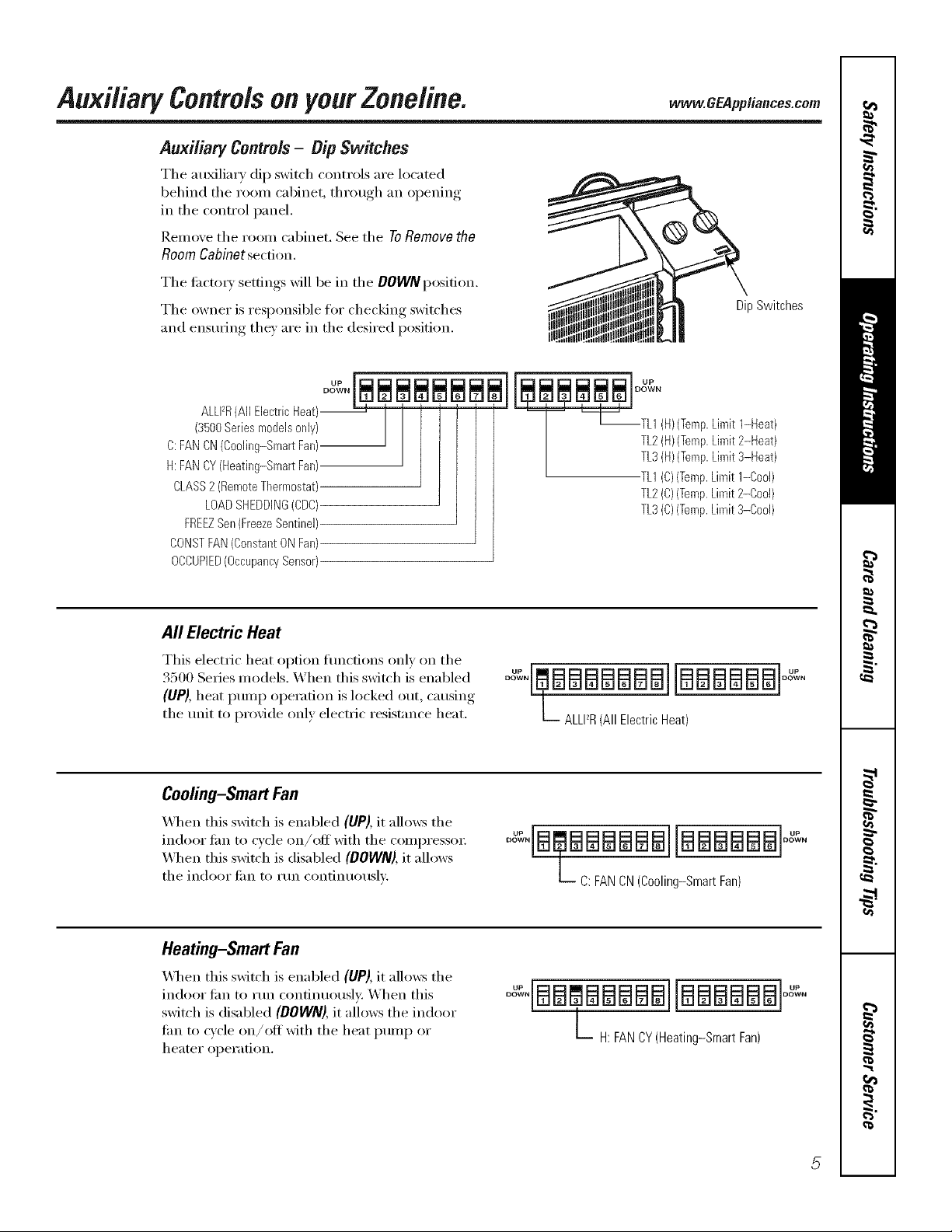
Auxiliary Controls- Dip Switches
The au_liary dip switch controls are located
behind the room cabinet, through an opening
in the control panel.
Remove the room cabinet. See the ToRemovethe
RoomCabinetsection,
The ti_ctox) settings will be in the DOWNposition.
The owner is responsible for checking switches
and ensuring the) are in the desired position.
DipSwitches
ALLFR(All Electric Heat)--
(3500Series models only)
C:FAN CN(Cooling-Smart Fan)
H:FAN CY(Heating-Smart Fan)
CLASS2 (RemoteThermostat)
LOADSHEDDING(CDC)
FREEZSen(FreezeSentinel)
CONSTFAN(Constant ON Fan)
OCCUPIED(OccupancySensor)
All ElectricHeat
This electric heat option flmcfions only on the
3500 Series models. X,_hen this switch is enabled
(UP), heat ptunp operation is locked out, causin,*,
the unit to provide only electric resistance heat.
Cooling-Smart Fan
_._]_en this switch is enabled (UP), it allows the
indoor lira to cycle on/off with the compressor
_._]_en this switch is disabled (DOWN),it allows
the indoor lira to run continuously.
J_og_N
TL2(H)(Temp.Limit 2-Heat)
T '_[_--TL1 (H)(Temp.Limit 1-Heat)
TL3(H)(Temp.Limit 3-Heat)
TL1(C)(Temp.Limit 1-Cool)
TL2(C)(Temp.Limit 2-Cool)
TL3(C)(Temp.Limit 3-Cool)
°°"'EmBBBBBBB][BBBBBB]° "
L ALLI_R(All Electric Heat)
oo : aaaaBailaaaaaaloo':
L C: FAN CN (Cooling-Smart Fan)
Heating-Smart Fan
\,_l_en this switch is enabled (UP), it allows the
indoor tim to run confinuousl); When this
switch is disabled (DOWN),it allows the indoor
lira to cycle on/off with the heat pump or
heater oper;ition.
° :'[BBCBBBBB]IBBBBBBI
L H: FANCY(Heating-Smart Fan)
Auxi/iaq controlsonyourZoneline.
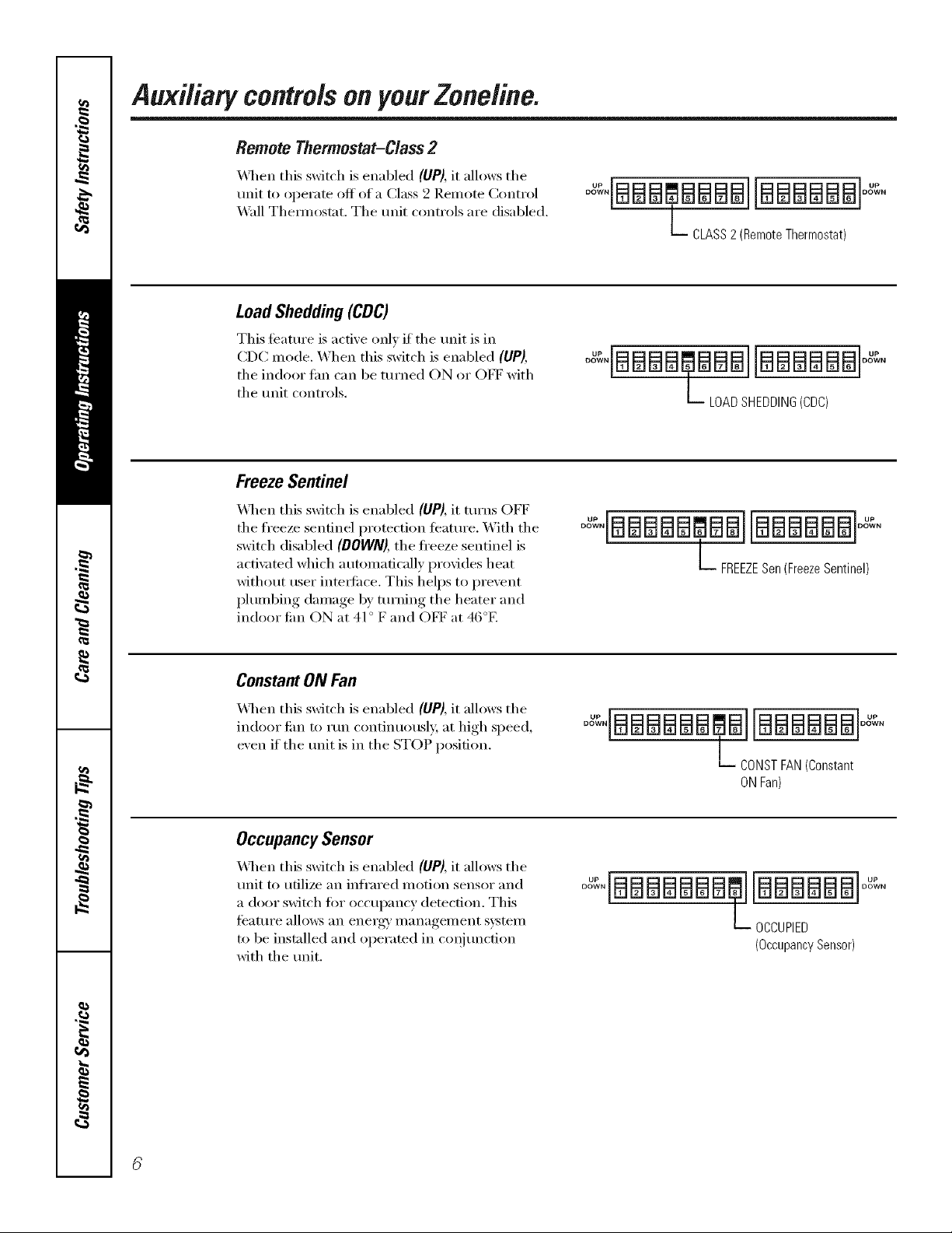
Remote Thermostat-Class 2
_4q_en this switch is enabled (UP), it allows the
unit to operate off of a Class 2 Remote Control
_4*all Them_ostat. The trait controls are disabled.
LoadShedding(CDC)
This teatm'e is active only if the trait is in
CDC mode. When this switch is enabled (UP),
the indoor Lm can be turned ON or OFF with
the Imit controls.
FreezeSentinel
\41_en this switch is enabled (UP), it turns OFF
the freeze sentinel protection teatm'e. _\]th the
switch disabled (DOWN), the fl'eeze sentinel is
acti\med which automatically provides heat
without user intet_tilce. This helps to prevent
plumbing damage by tm'ning the heater and
indoor Jim ON at 41° F and OFF at 46°E
°_IBBB_,BBBBIIBBBBBBI°_
b CLASS2(RemoteThermostat)
°o'-'°IBBBBaB ]IBBBBBB]°o°-'°
L LOADSHEDDING(CDC)
°°"'IBBBBB BBIIBBBBBB]°o""
L FREEZESen(FreezeSentinel)
Constant ON Fan
X&q_enthis switch is enabled (UP), it allows the
indoor tim to mn continuously, at high speed,
exert if the trait is in the STOP position.
Occupancy Sensor
_,_l_en this switch is enabled (UP), it allows the
Imit to utilize an infi'ared motion sensor and
a door switch fin" occupancy detection. This
teatm'e allo_vs an energai management system
to be installed and operated in coqim_ction
with the tmit.
°_°IBBBBBB_,BI[BBBBBB°_"°
b DONST FAN(Constant
ON Fan)
0o_,BBBBBBB@J[BBBBBB °_°
L OCCUPIED
(OccupancySensor)
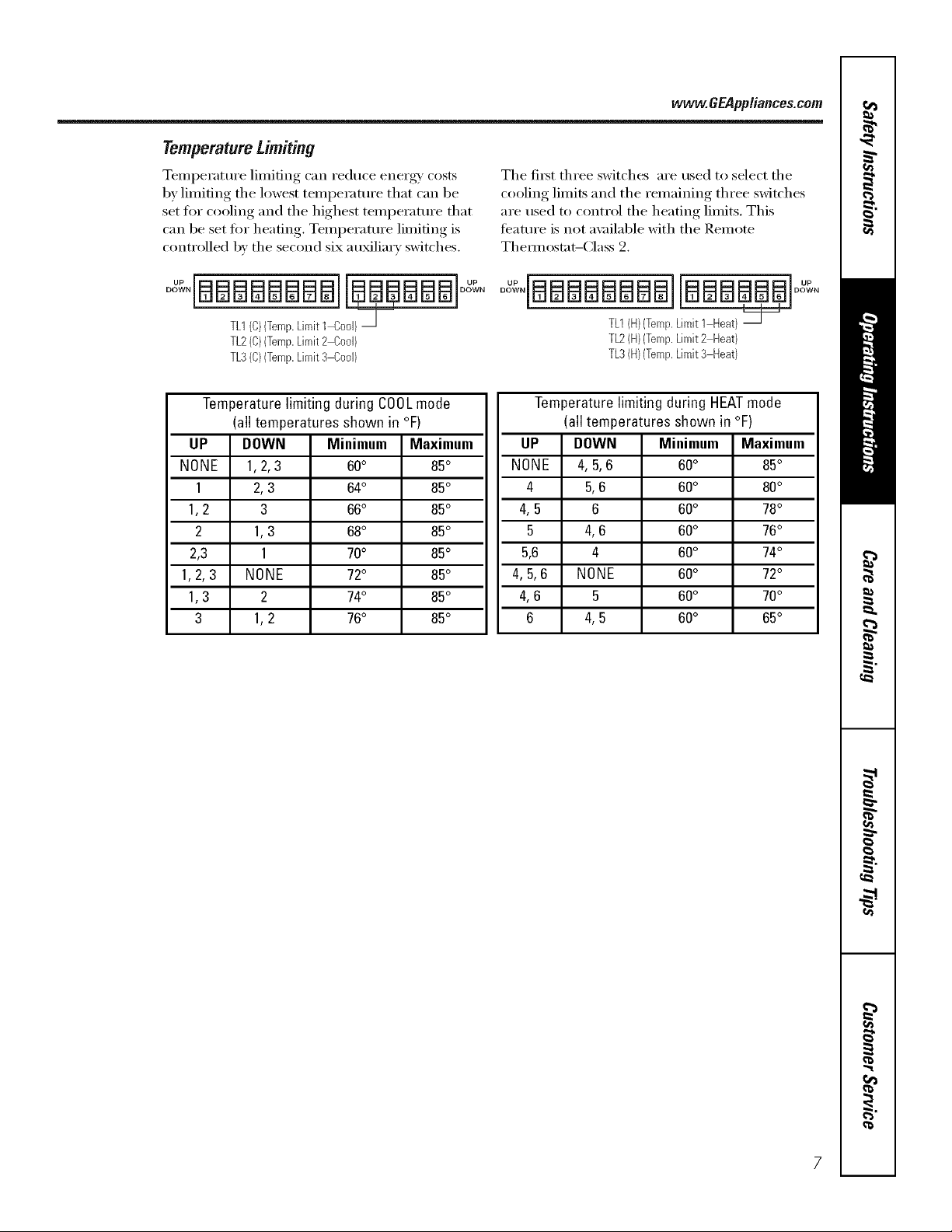
Temperature Limiting
Temperature limiting can reduce enex%_' costs
by limiting the lowest temperature that can be
set fl)r cooling and the highest temperature that
can be set fin" heating, Temperature limiting is
controlled by the second six au_liarv switches,
TL1(C)(Temp.Limit1 Cool)_
TL2(C)(Temp.Limit2 Cool)
TL3(C)(Temp.Limit3 Cool)
www.GEPppliances.com
The fit_t three switches are used to select the
cooling limits and the remaining three switches
are used to control the heating limits, This
teature is not a\_filal)le with the Remote
Them_ostat-Class 2.
o .iaBaaaaaailaaBa a]oo .
TL1(H)(Temp.Limit 1 Heat)
TL2(H)(Temp.Limit2 Heat)
TL3(H)(Temp.Limit3 Heat)
Temperature limiting during COOLmode
(all temperatures shown in °F)
UP DOWN Minimum Maximum
NONE 1,2, 3 60° 85°
1 2,3 64° 85°
1,2 3 66° 85°
2 1,3 68° 85°
2,3 1 70° 85°
1,2,3 NONE 72° 85°
1,3 2 74° 85°
3 1,2 76° 85°
Temperature limiting during HEATmode
(all temperatures shown in °F)
UP DOWN Minimum Maximum
NONE 4, 5,6 60° 85°
4 5,6 60° 80°
4,5 6 60° 78°
5 4,6 60° 76°
5,6 4 60° 74°
4,5,6 NONE 60° 72°
4,6 5 60° 70°
6 4,5 60° 65°
Auxiliary controlsonyourZoneline.
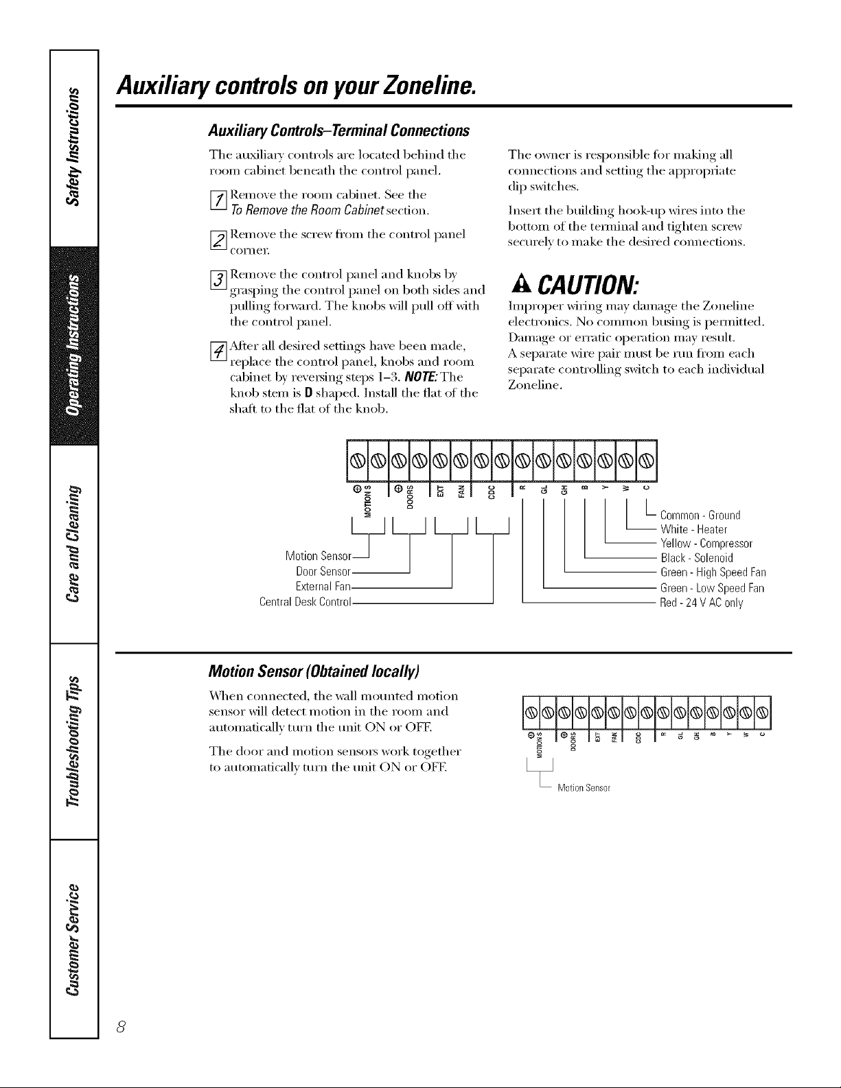
Auxiliary Controls-TerminalConnections
Tile ml_li_' cont_'ols _'e loc_ted behind tile
_'oom cabinet bene_th the cont_'ol p_mel.
_] Remo_,e the _'oom c_binet. See the
ToRemovethe RoomCabinetsection.
[_gem o_e the sc_'ew ti'om the c'ont_'ol p_nel
Coi'nei;
The owne_" is _'esponsible fi_" m_king _11
com_ections _md setting tile _l)l)rOl)_i_te
dip switches.
lnse_'t tile building hook-/_p wi_'es into tile
bottom of the teH_/in_l _md tighten sct'ew
sectu'elv to m_ke tile desi_'ed com_ecfions.
[_] Remoxe tile cont_'ol p_mel _md knobs b)'
grasping the cont_'ol pm_el on both sides _md
pulling fi)_'w;_'d. The knobs will pull off with
the cont_'ol p_mel.
[_Mte_" _ll desi_'ed settings l/_ve been m_de,
_'epl_ce tile cont_'ol pm_el, knobs m_d _'oom
cabinet b)' _'e\'e_ing steps 1-3. NOTEJThe
knob stem is O sh_ped. Inst:_ll the fl_t _ff the
slip,it to the fl_t of the knob.
og
g g
o
Door Sensor
MotionSensor_J L_ L L_
External Fan
Central Desk Control
Motion Sensor(Obtained locally)
_,_q/en com_ecte(1, tile w_ll motmted motion
sensor" will detect motion in the _'oom _md
mm_m_fic_llv ttu'n tile trait ON o_" OFE
Tile (loot [lIl(1 i/lotion sensoi3 wol'k togethei"
to m_tom_atic_allv ttu'n tile trait ON or OFE
CAUTION:
Improper" M_ing m_y clam_ge tile Zoneline
elect_'onics. No common busing is pem_itted.
D_m/_ge o_"er_'_tic oi)e_'_fion m_y _'esult.
A sei)__m wi_'e i)_i_"i/ltlst be mn fl'om e_cl/
sei)_'_te cont,'oiling swit('h to e_cl/in(lividt_l
Zoneline.
L-common- Ground
White - Heater
-- Yellow- Compressor
Black- Solenoid
Green - High Speed Fan
Green- Low Speed Fan
Red- 24 V AConly
@_@@@@@@@@@@@@---1
eo__ le_ I_ _1 o_ i _ _ _ ....
Motion Sensor
8
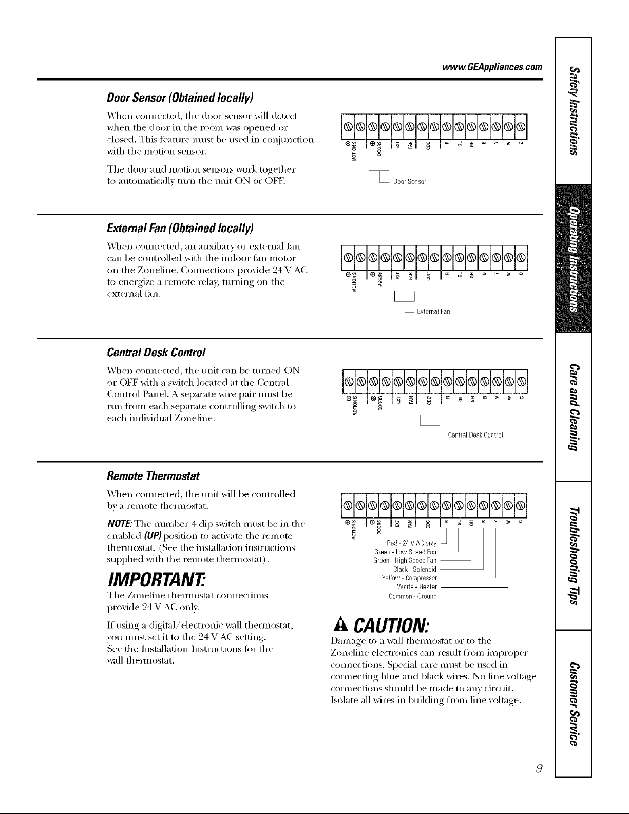
Door Sensor (Obtained locally)
_]/en connected, tile door sensor will detect
when tile door in tile i'OOill W_lS opened or
closed. This teatm'e must be used in coI_junction
with tile motion senso_:
The door and motion sensm_ work together
to automaticallx mrn tile refit ON or OFE
External Fan(Obtainedlocally)
_41/en connected, an auxiliary or external tim
can be controlled with tile indoor tim motor
on the Zoneline, Connections provide 94 V AC
to energize a remote relay, turning on tile
external tim.
Central Desk Control
vvww.GEAppliances.com
@@@@@@@@@@@@@@
2
" DoorSensor
g
[_ ExternalFan
X_l/en com_ected, tile refit can be turned ON
or OFF with a switch located at the Central
Control Panel. A separate wire pair must be
run fl'om each separate controlling switch to
each individual Zoneline.
Remote Thermostat
X_q/en connected, tile refit _fill be controlled
bv a i'elllote thelillostat.
NOTE'The number 4 dip switch must be in tile
enabled (liP)position to acti\'ate tile relnote
them_ostat, (See the installation instructions
supplied with the remote them_ostat),
IMPORTANT
Tile Zoneline them_ostat connections
provide 24 V AC onE'.
If using a digital/electronic wall them_ostat,
you must set it to tile 24 V AC setting.
See tile Installation Instructions for tile
wall them_ostat.
@
[_ CentralDeskControl
Red 24VAC only
Green- Low SpeedFan
Green High SpeedFan
Black- Solenoid
Yellow Compressor
White - Heater
Caermon Ground
A CAUTION:
Damage to a wall them/ostat or to tile
Zoneline electronics can result fl'om improper
connections. Special care must be used in
cmmecting blue and black wires. No line w)ltage
connections should be made to any circuit.
Isolate all wires in building fl'om line w)ltage.
 Loading...