

Page 1
o_
Safety Instructions ........... 2
Operating It_truc_iot_
Air [)ire_ tion ................. 4
Auxilia W (:ontrols ........... 5-9
Controls ..................... 3
+I_)Remove the Room Cabinet . .4
+x2nt Control ................. 4
ge.com
Heat/Cool Modal 2900
Heat Pump Modal 3900
Espa_ol
©
Care and Cleaning
Air Filters ................... 11
Base Pan ................... 10
()utd oor Coils ............... 10
Rooln Cabin<l and (;as<: ....... 10
Vtnt Fih<r . ................. tO
h_stallation IrL_tructions
Ele( tri(al C_onnet tim: ...... 14-17
Installing the Zoneline ..... 18, 19
()ptional Drain Kit ........... 20
Preltaration ................. 12
Replacing at: Existing Unit? . . . 13
'lroubleshooltng "lips ...... 1, 22
Normal Operating Sounds ..... 23
Consumer Support
(:onsumer Sttpport .... Bark Cover
Product Registration ...... 25, 26
Warranty ................... 27
For a Spanish version ot tiffs
manual, visit our Wcltsite at
Para consuhar tma version
_n _spaflol de este manual
d_ insmtcciones, visit<: nuestro
sitio de interne: ge.com.
Fran_ais
For a Fr< rich version of this
manual, visit our Wcltsite at
w_v.elect romenagersge.ca.
Potu un version h-am, ais de
ct matm<:l d'utilisation, w:uill<!z
visit<!:- notre sit< web _'ll'a(h-_ sse
•_vw.elec t roln ellage rsge.< a+
Writethe modelandserial
numbershere:
Model #
Serial #
Find these hum|): rs on _1label
behind th¢ room cabinet on th¢
base pan.
TINSEA530JBRZ 49-7592 02-08dR
Page 2
IMPORTANTSAFETYINFORMATION.
READALLINSTRUCTIONSBEFOREUSING.
WARNING!
Foryour safety, the information in this manual must be followed to minimize the risk of fire or
explosion, electric shock, or to prevent property damage, personal injury, or loss of life.
SAFETYPRECAUTIONS
• This Zonelin(' must be prOp(T[y
installed in a_ordanc(' with the
Installation Instructions betbr_ it is
used. See the Installation Instructions
in the back of this manual.
R< place imm( diat(ly all (le(tric service
cords tha_ have becom( h-,,yed or
otherwise damag( d. A damag( d [)(>_t_*"
supply cord must be tel)laced with a
new pow(r supply coI*l obtained ti-om
the manufhcmrer and not repaired.
Do no{ use a cord Hint shows cm(ks
or abrasion damage along its length
or at either the plug or (onnector end.
Utq)lug or disconnect the Zoneline at
the fklse box or cir(uh breaker b(fbre
making any repairs.
NOTE:We strongly r< commend that any
servking be performed b?, a qualified
itldix idual.
Replach)g an existing unit?
For details, see th(: hlsmllation
[tlStl'UCIiOI]S itl lhis manual.
",,._'_ READANDFOLLOWTHISSAFETYINFORMATIONCAREFULLY.
_ O,t.I\_ SAVETHESEINSTRUCTIONS
2
Page 3
Aboutthe controlsonyourZoneline. go.corn
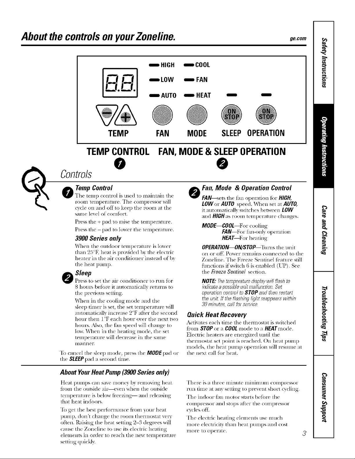
IHIGH ICOOL
r-Q r-_.,] IAOTO i HEAT
-.0w --FA.
TEMP FAN MODE
TEMPCONTROL
FAN,MODE& SLEEPOPERATION
O
| Temp Control
Gr The t_m l) conlrol is used lo maintain lhe
Controls
FOOIll lellll)el'_llllFe. The COllll)l-(SSOl-will
(7,'c1¢on and off to ke(l) lll( l-O(>ln_1[Ihe
S_/lll( level of COIII[})I-I.
Press the + pad Io caise the tempemtnr(.
Prtss the - pad to lower the temperatu re.
3900 Series only
When lbe outdoor tempel-atme is lower
thml 25"F. heat is provided by the elecuic
hearer ill the air (onditioner instead of b}
tile heat pump.
Sleep
Pr(ss t,.)s(t the air (,.)ndition( r t,.)run fbr
8 houps belbre it m_tomaticallv returns to
the pr( vi(>tB setting.
10r]lell in the cooling mode and the
sleep timer is set, the set mml)eramre will
mltomaticall} increase 2°F ati{r the second
hour then l <>17each hour (>,,'el tile next two
houps. Nso, tile fan speed will change to
low. When ill th_ heating mode, the s(t
tempecature will decrease in the stone
lnitlllleL
To canc(l th_ skep mode, press Ihe MODEpad or
file SLEEPl)adase(ond lim_.
I I
SLEEPOPERATION
@
@Fan, Mode & Operation Control
FAN---_etslhe t_m operation fi:>rHIGH,
LOWer AUTO sp_<d. When s_l al AUTO,
it automati(allv _,wil(hes between LOW
and HIGH as r(>om tenll)eratur( (hanges.
MODE--COOL.or cooling
FAN--For rim-only operation
HEAT--D)r healing
OPERATION--ON/STOP--I'ums tile unit
on or off. I)o_er remains (olmetted to the
Zoneline. The Fr_ eze Semin(l tbamre still
flmctions it s;'_itch 6 is enabled (UP). See
tile Freeze Sentinel section.
NOTE:7hetemperaturedisplaywill flashto
ladlaateapossibleunitmaltanctionSet
operationcentre/to STOPandthenrestart
theuni_/f the flashinglightreappearswithin
30mlaute&carlforservice
Quick Heat Recovery
.\ctivatcs (uch time thu thermostat is _wit(b(d
fi-om STOP or _ COOLmode lo _1HEATm<_le.
Elcctri( heatec, arc energiz(d until tilt'
themlostat set point is reached. On heat pmnp
models, tile heal pump opel'4tion will resume at
the next (:all for heat.
About YourHeat Pump(3900Series only)
Ileat i)umps can save mone) by relnoving heat
from the outside air--even when the outsi(le
leml)eF, mn-e is 1)elow fi-eezing-- and releasing
thai heat indoors.
"['_)get the best performance from }our heat
pump, don't change the room them_ostat velw
ol:tt,n. Raising the heat setting 2-3 degrees wili
cause the Zonelin( to use its electric heating
elements ill ol_(]el- 1o reach the lieN telnpel_dtllle
setting quiekl>
There is a three minute nfinimmn c()ml)ressor
mn time at any setting to l)r(,venI shol_ (3'(ling.
The indoor fan motor starts befbr( the
COIIIDIX'SSOI" all(1 slops ;J_l( r the Colnpressof
cycks oft
The electric heating el{ m{ nls use nmcb
more electricit} than heat pmnps an(I cost
lllole It) opel_ll('.
3
Page 4
OtherfeaturesofyourZoneline.
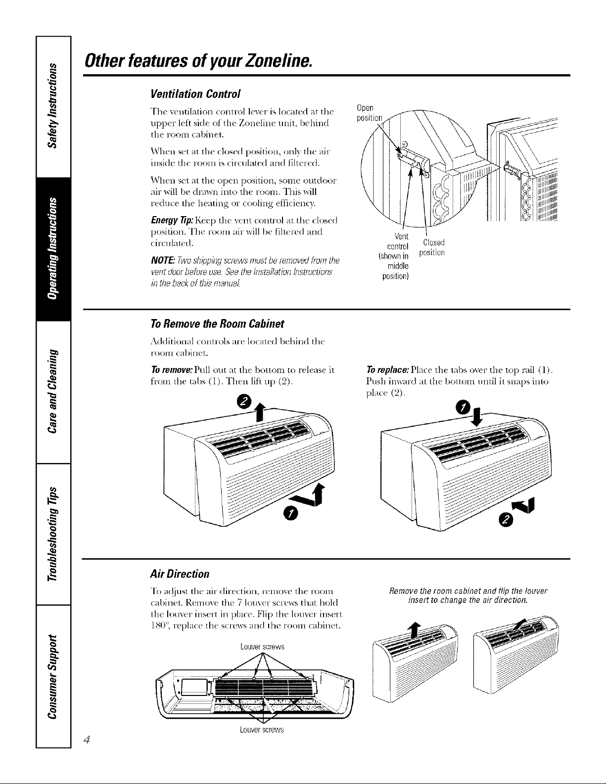
Ventilation Control
The ventilation control lever is located at the
upper left side of file Zoneline unit, behind
file room cabinet.
When set at the closed position, only the air
inside the room is circulate(1 and fihered.
When set at the open position, some outdoor
nil-will be &-mvn into the room. This will
reduc( the heating or cooling dlicien_x.
Energy 77p:Keep the vent conn-ol at the closed
position. The room air will be filmrcd and
circulated.
NOTE:Twoshippingscrewsmustberemovedfromthe
ventdoorbeforeuse Seetbefl}stallation/nstructinns
in thebackofthismanua_
ToRemove the Room Cabinet
Additionul ( ontrols arc lo(ut(d behind thu
l-OOln cabinet.
Toromove:Pull out at the bottom to rcleas( it
from the tabs (1). Then lift up (9).
Open
position
Closed
position
To replace: Pla(( th( labs ov(r tile lop rail (l).
Push imvard at the bottom umil it snaps into
[)lace (2).
Air Direction
'Ib a(!iust the air direction, remo_e the room
cabinet. R_move lhe 7 louv_r scruws that hold
Removethe room cabinet and flip the louver
insert to change the air direction.
the lomer insert in place. Flip lhe louvcr insert
180°, replace the screws and the room ca/)inet.
Louverscrews
Louverscrews
4
Page 5
Auxiliary ControlsonyourZoneline. go.corn
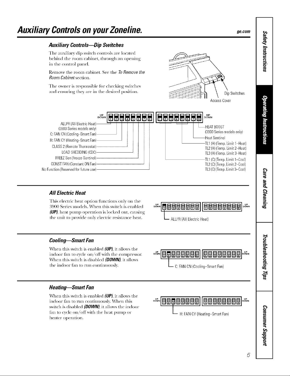
Auxiliary Controls---DipSwitches
The allxiIial T dip switch colm-ols arc located
behind tile room cal)inet, through all opening
in tile control panel.
Remove tile room cabinet. See tile To Remove the
RoomCabinets(orion.
The owner is responsible fbr checking switches
and ensuring they are in the (lesir_ d po@ion.
ALLFR(All EbctricHeat)_
(3900Seriesm0dels0nly) ] I / I
D:FANDN{CoolingSmartFan/ I I I
H:FANCY(HeatingSrnartFan) J ]
CLASS2(RemoteThermostat)
LOADSHEDDNGCDC
FREEZSen(FreezeSentinel)
CONSTFAN(ConstantONFan)
NoFunction(Reservedforfutureuse}
L;% S0d2m0de's0n','
TL2{H)(Temp.Limit2-Heat}
TL3(HI(Temp.Limit3 Heat)
TL1{C}(Temp.Limitf-Cool}
TL2(C}(Temp.Limit2-Cod}
TL3(C)(Temp.Limit,'_Cool)
DipSwitches
AccessCover
All Electric Heat
This electric heat option filnctions only on tile
39!)0 SmJes models. When this switch is enabled
(UP),heat pump operation is locked out, causing
d_e unit to provide onl3 electric resistance heat.
Cooling---SmartFan
When tills swiwh is enabled (UP), it allows flit'
indoor fhn to rs"cle on/off with the c()mpressol;
When this switch is disabk d (DOWN), it allows
th( indoor thn m mn COllfilltlOtlsl}c
Heating---Smart Fan
When this switdl is _nabkd (UP), it _lllows the
indoor I'_LIIto lun (ontinuousb,: _,Vh('n this
switch is disabled (DOWN), it allows th( indoor
fhn 1o cycle on/ofl'wilh the heat pump or
heater operation.
oqemmmmmmmllmmmmamaal
L ALLFR(AllElectricHeat)
oqEa aaaaNaNIIBaaaaaaEaloo,'o
L-- C:FANCN(Cooling-SmartFan)
oqam mmmmmllmmmmmmmml
_-- H:FANCY(Heating-SmartFan)
5
Page 6
Auxiliary controlsonyourZoneline.
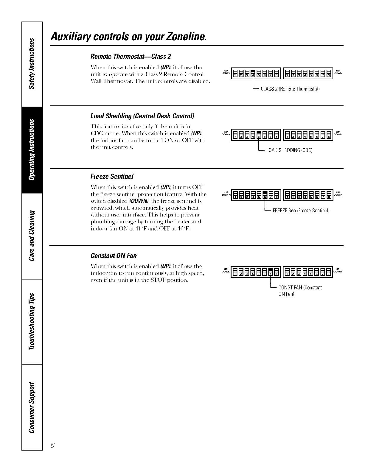
Remote Thermostat--Class 2
When this _wilch is cnabh'd (UP), it allows the
unit to opecate with a Class 2 Remote Control
Wall TheHnostat. The unit controls ar( disabled. oqBB qe qaB qllBB qB qBB qlo* ,
Load Shedding (Central Desk Control)
This fk'aturu is al tivc old 7,it the refit is ill
CDC m<xle. When this switch is <nabled (liPS,
the indoor fhn can be turned ON or OFF with
the unit controls.
FreezeSentinel
When this swilch is enabled (UP),it turns OFF
lhe f}eeze sentinel protection fi,amre. With the
switch disabled (OOWN},th_ freeze sentinel is
activated, which amomalically provides heat
without riser interi3_ e. This helps 1opruvent
plumbing damage by turning the hearer and
indoor tim ON at 41"F and OFF at 46"K
L._ CLASS2 (RemoteThermostat}
oqaaaa aaEallawaEaEaaawl° °
_- LOADSHEDDING(CDC)
oqaaaaw allaaaaaaa alo °
FREEZESen(FreezeSentinel)
Constant ON Fan
When this swit(h is enabh'd (UP), it allows tht"
indoor fhn u) lanl continuously, at high speed,
even it the unit is in the STOP p<Mtion.
L CONSTFAN(Constant
ONFan)
6
Page 7
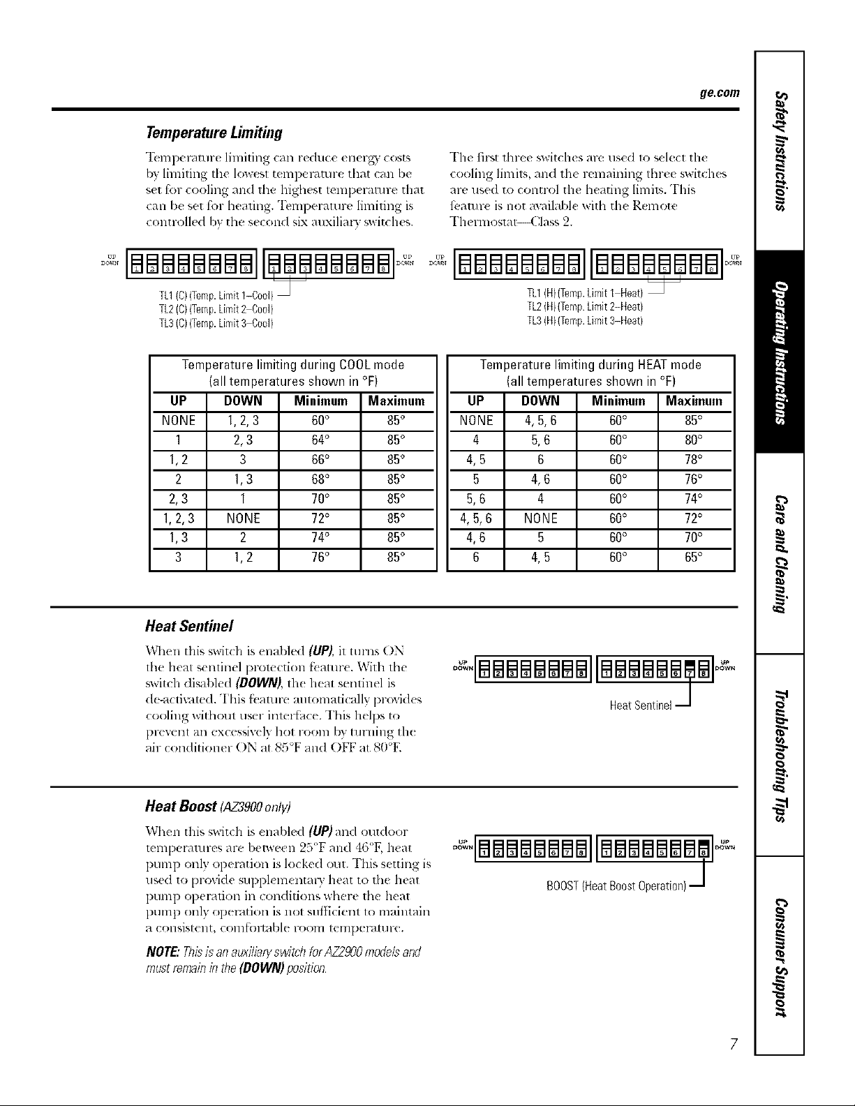
TemperatureLimiting
"Ik,mpemrnr( limiting can reduce energy" cost',
by limiting tile lowesl tempel_l.ture that {an be
set fk)l-cooling and the highest tenlpel-aru re that
can be set fbr heating. "IbmpeF4mre limiting is
controlled b) the second six auxilial y _witches.
ge.com
The first three _witches are used 1o select tile
cooling limits, and tile remaining fln-ee switches
are used to control tile heating limits. This
fbamre is not aw_ilable wilh the Remote
Thermostal Class 2.
[BB I BBBBBI
TL1(C)(Temp.Limit 1-Cool)
TL2(C)(Temp.Limit_Coo])
TL3(C)(Temp.Limit%Cool)
Temperature limiting during COOLmode
(all temperatures shown in °F)
UP DOWN Minimum
NONE 1,2,3 60°
1 2,3 64°
1,2 3 66°
2 1,3 68°
2,3 1 70°
1,2,3 NONE 72°
1,3 2 74°
3 1,2 76°
Heat Sentinel
When this switch is enabled (UP),it rams ON
lhe heat senlinel protection f_ atm-_. With tile
switch disabled (DOWN),th_ heat sentinel is
de-a_ti_lted. This f_amrc mlromati< ally provides
cooling without user inmr{hce. This helps to
pFe'_elll all excessively hot F001n by tm-ning th(
air conditioner ON at 85°F and OFF at 80°E
Maximum
65°
85°
65°
85°
85°
85°
85°
85°
IBBBaBBBBIIBBBaBBBBb
TL1(H)(Temp.Limit I Heat)
TL2(H)(TempLimit2-Heat)
TL3(H)(Temp.Limit3-Heat)
Temperature limiting during HEATmode
(all temperatures shown in °F)
UP DOWN
NONE 4,5,6
4 5,6
4,5 6
5 4,6
5,6 4
4,5,6 NONE
4,6 5
6 4,5
o qBBeaBaBallaaaaaeffalo .
Minimum
60°
60°
60°
60°
60°
60°
60°
60°
HeatSentinel
Maximum
65°
80°
78°
76°
74°
72°
70°
65°
Heat Boost (AZ3900on/)/)
When this switch is enabled (UP)and outdoor
mmperamres are between 25°F and 46<'F,heat
I)tnnp only operation is locked out. "Ellis setting is
use(] to provide supplenlental T heat to tile heat
pump opel_/fion ill conditions where tile hea*
l)unq) only opm-,ition is not sui}]cient 1o maintain
a consistent, coln_)ltable l-OOlll temperartll-e.
NOTE,"Thisisanauxiliaryawitdl forAZ2900tnodeband
mustremainb the(DOWN)podtion
7
Page 8
Auxiliary controlsonyourZoneline.
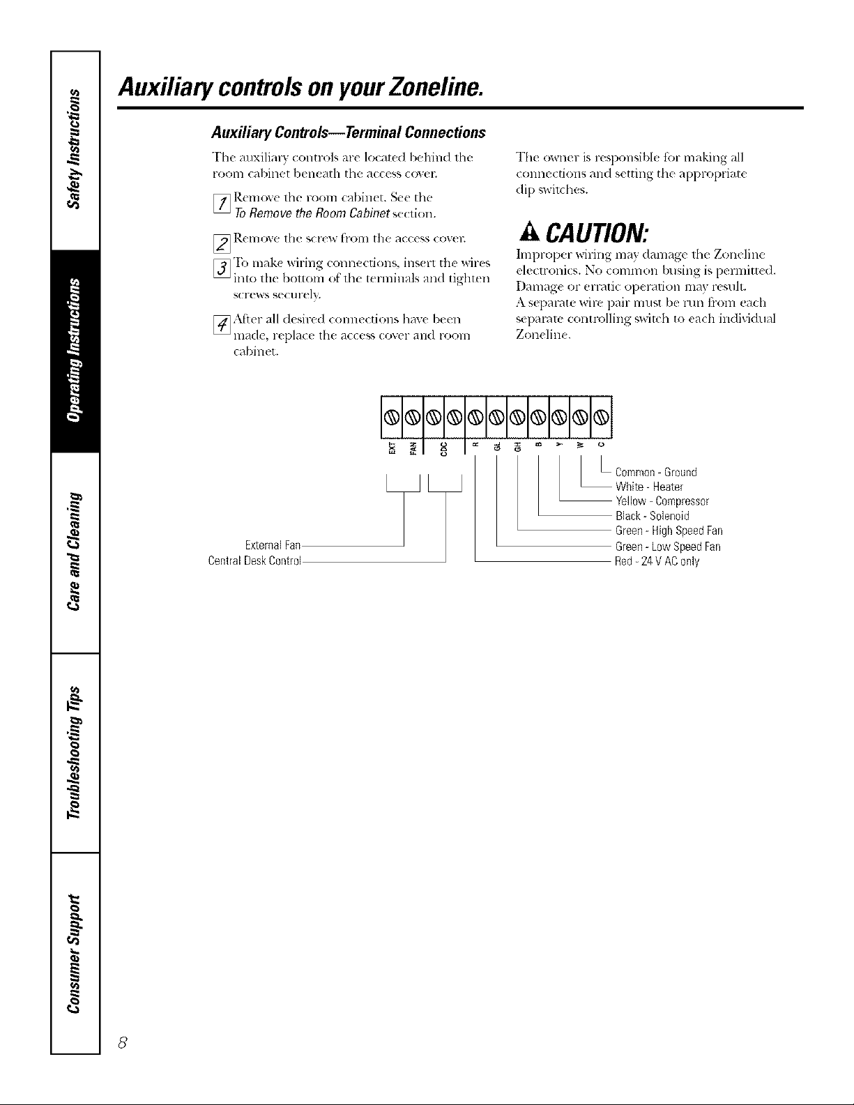
Auxiliary Controls--Terminal Connections
The auxiliary _ontrols are lo_at_d behind die
i-ooi_] cabinet ben_ ath the access (ovel;
[_ Rc move the room cabinct. See the
ToRemove the Room Cabinet section.
_]_.(lll(Ae t|l{ S(l(w[rOlll []l(t _l(((_;s (o\(111
[_'Ib mak( Mring connections, ins( rt the wires
into lh( [)ol[Olll ()f'lhe terminals aim tighten
SCI'(?'_ S S(?Cl Irely.
[_ A[ier all desired connections have been
ln_?(l(!, replace the access cover _111(Ii-(tOill
cabinet.
=__1 _ I e__ _=o
The owner is resl)onsibl_ for maldng all
connections and s(tting the al)l)rol)rial(
di l) _,wil(:hes.
A CAUTION:
hnproper wiring may damage the Zoneline
electronics. No common busing is permitt(d.
Dalllag( or erratic o])el_ttioll illay l-(*Sl/lt.
A separ, lte wire i)air must be mn ti-om each
sei)arnm controlling _,wit_h to each individual
Zoneline.
ExternalFan
CentralDeskControl
Yellow- Compressor
Black- Solenoid
Green-HighSpeedFan
Green- LowSpeedFan
Red-24 VAConly
8
Page 9
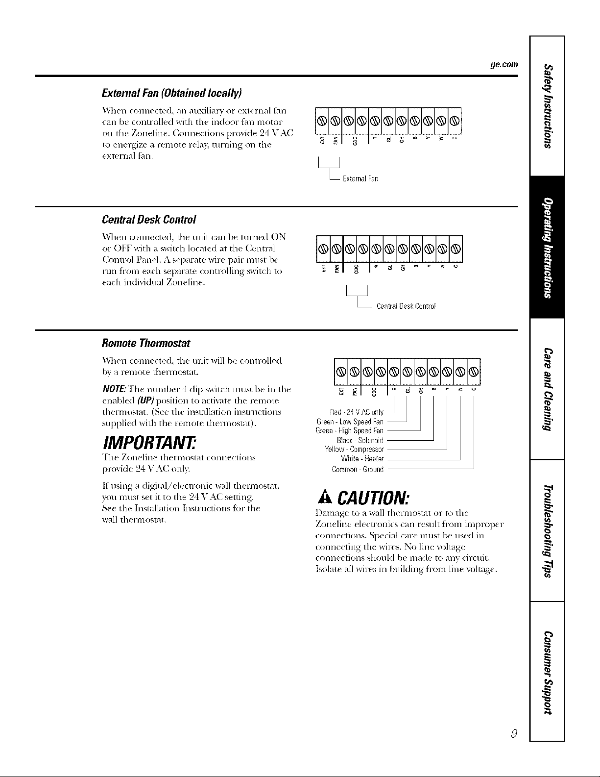
External Fan (Obtained locally)
When connected, an anxilim) or external thn
(an be controlled with the indoor fhn motor
oll the Zoneline. Connections provid( 24 V.\C
1o energize a FelllOle rt.lay, tlll'l]illg O11 the
exmrnal thn.
Central Desk Control
When (onne(ted, the unit (an be turned ON
or OFF with _lswitdl lo(ated _Jt the (_entml
Conn-ol Panel. A separate wire pail- must be
mn ti-om each separam controlling switch to
each individual Zoneline.
Remote Thermostat
ge.com
®®®®®@®®®®@
[_J ExternalFan
®®®®®@®®®®®
[_ CentralDeskControl
When (onnected, the trait will b( controlled
by a remote Ihennostat.
NOTE:The number 4 dip '_witch must be in tile
enabled (UP) position to actiw_z( the remote
thermostat. (See the inslxlllafion instructions
supplied with th( remote thel-most_lt).
IMPORTANT
The Zoll( lille Ihel-lllOS[_?I (olllle(liolls
l)rovide 24 V AC only.
If using a (/igiml/de(lroni( wall thermostat,
you musl sel it to, lhe 24 V A(] selling.
S(e the Inslallation Instructions for the
_all Ihel-D]os[_][,
®®®@®®®@®®®
Red-24VAConly
Green-LowSpeedFan
Green-HighSpeedFan
Black- Solenoid
Yellow- Compressor
White- Heater
Common- Ground
A CAUTION:
Damage to a wall flmrmostat ol- to the
Zoneline d_ ctronics can resuh t]-(tm imwoper
connections. Sp(cial c_lre nmst be used ill
connecting tile wires. No line vohage
connections should be made to any circuit.
Isolate all wires in building fiom lin( voltage.
9
Page 10

Careandcleaning.
Room Cabinet and Case
Turn the Zoneline off and distonmxt flw
power suppl3;
OutdoorCoils
The coils Oll tile outdoor side of tile Zoneline
should be checked regularl?: If they are clogged
with (lill or soot, th( T may be prot_.ssionally
steam cleaned, a smMce awfilable through your
GE sel-vice outlet. You will need to remove tile
unit to inspect the coils b(cmlse the dil_
buildu l) OCCln_ on th( inside.
Base Pan
Ill somu installations, dirt or other debris may bc
blown into the unit from th_ outside and settk ill
th_ base pan (the bottolll of the unit).
"Ii-_clean, use wamr and a mild detergenl.
Do not use bleach or abrasives. Some commercial
cleaners may damage the plastic l)arts.
Coils
Grille
Clean the outside coils redularlg
In some areas of tile L hilt d States, a "g(l-lik( " or
'slime-like" suLstmlce mm bc seen in the base [)an.
Check it peliodicall 3 and clean, if neeessal T.
Ventilation Filter
If fi_e ventdooris open,clean the vent filter twice a year
or ast_qt.?ed
TuretheZoneliae off beforecleaning
Toremove the ventfilter.
• Remove the room (id)inut. Set' the ToRemove,
the Roren Cabh?etse(tion.
• Rtqtlove the _(fll 1 SCl-exvs seCtllillg t he tl nit
flanges to the cas(.
• Slide the unit fi-om the wall case.
• Grasp the vent filter tab and pull the tilt( r out
by sliding it to the right.
Toclean the vent filter,"
• Run water flnough the fih('r from tht"
back side.
• DI? thoroughly befbru replacing.
10
Page 11

Tomaintain optimum performance, clean the filters at least every 30 days.
Air Filters
Toremovetheairfilters:
ge.com
Dirtyfgte_Needs cleanfllg Cloggedfilte_Greatly
reducescooling ileating
andairflow
Turnthe Zeneline off before cleaning.
The most important dling you cm] (Io to
maintain the Zoneline is to clean the fiher
at least (v(Iy _'0 dav_. Clogged fihers redu( e
cooling, heating _ll](t air flow.
Keeping these filters clean will:
• [)('cr_ _lsc cost of' opcn_tion.
• Save energ 3.
• Prexenl clogged heat exchangel- coils.
• Reduce tile risk of premature component
tidlure.
Toclean the a# Ftlters:
• Vat uum off dw hcaxy soil.
• Run water through tile filt_ l-sfrom th_
back side.
• DW thoroughly befbl* ruplacing.
NOTE:The ail- fillers are intel-changeable
and will tilt in either the light or left side.
Toreplace the air filters:
Pushdown
A CAUTION:Ooeutoperutethe
Zoeeliee without the filters in place, ff a filter
becomes torn or damaged, it should be replaced
immediately.
Operating x_ithotlt tile filte_s it] place or with
damage(I lille rs will allow dirt and dust to reach
th_ indoor coil and reduce the cooling, h_ afing,
airflow and eltici_ nov of the trait.
Replacement filtel_ ave available fl-om your
saleq)el-son, GE dealm, (;E Se]wice and Pal-ts
Centel- or authorized (_tlSlOlllel-(_al-e_ selwicers.
!!
Page 12

Installation
Zoneline Air
Instructions
Conditioners
I Questions? Call 800.GE.CARES (800.432.2737)or Visitour Websiteat:ge.com
BEFORE YOU BEGIN
Read these instructions completely and carefully.
• IMPORTANT - s_,,,th,_,
instl-tl(tiOllS ['or lo<al ill_,p( ClOlJS llSe.
• IMPORTANT - obs.,, _.
_OVel'llill_ (o(](!s _111(] ol-dillall{ (s.
• Note to Installer - Be sur_ to h,av_ daes_
instru(ti(ms with the: o_%:ii(1.
• Note to Owner - I-_eep th{se insu-uctions for
filmre rdi:rence.
• Propcr installation is th_ r_ sponsibility of th_
ir_stallela
• Producl t dlure due to improp_ r inslallali,.m is not
{,.r,{ r<d u nd(r th{ '_VitlT_llll)'.
TOOLS YOU WILL NEED
Phillipsscrewdriver
IMPORTANT ELECTRICAL
SAFETY--READCAREFULLY
_k CAUTION:
• Follow the National Electrical Code (NEC) or local
codes and ordinances.
• For personal safely, this Zoneline must be properly"
gromlded.
• Protective devices (fuses or circuit breakers)
acceptable for Zoneline installations m-e specified
on the nameplate of each unit.
• Do not use ml extension cord with this unit.
Alunfinum building Mring may present special
problems--consult a qualified electrician.
When the unit is in the OFF position, there is
still voltage to the electrical controls.
Disconnect the power to the unit before
servicing by':
1 Removing the power cord (if it has one) from
the wall receptacle.
OR
2 Removing the branch circuit fuses or turning
the circuit breakers off at the panel.
ZONELINE COMPONENTS
Exteriorgrille/louver
Wailcase*_--_
Shipped with the Zoneline unit
_ Checkthe "Essential Elements" liston the unit
--- Zonelineunit -Roomcabinet_
--Powersupplykit*_
12
Page 13

Installation Instructions
REPLACING AN EXISTING UNIT?
Check the "Essential
Elements" label for
impotlant information.
Use the correct wallcase
This unit is designed to be installed in a GE plasti( or
insulaled melal x_v_llcase. This minimizes condensation
Iron1 fornfing Oll the room sid( of the case.
lithe ctlrl-tqlt wall (:as( is not insulated, 7,'ou can reduce
the possibili V ot cond( llSadon tbnning by installing
insulation kit I_\Kg0IL, a_dlable whel*! you purchased
th( unit.
NOTE: There are several extra boles in tbe unit side
t]angcs tbr installation in wall cases otber than C,1L
"I'o avoid damaging tile flange insulation, the installer
should use an awl or other sharp tool to puncture tbe
insulation in the apl)ropriate holes l)etbre installing
th_ attachment screws.
Replacing a ducted unit
New ducted installation:
It tiffs trait is to bc installed in a ll('W ductcd application
using a duct adapter kit, the kit must be installed befbre
the unit is pla_ ed in the wall (:as(. The installation
instructions are packed witb the kit.
#ate
Existhlg ducted installation:
Replacement of an existing ducted unit may rcqub-e
difli..rent (onq)onent',. Request this intbHnation fl-om
_k)lll" sales l-e[)Feseiltative.
• Replacing 230/208 volt traits:
See page 14.
• Replachlg 265 volt traits:
See pages 15 and 16.
Use the correct outdoor ,grille
You should use tbe outdoor grilh's shown oll the
"Essential Elements" label on the top of lbe tlllil.
• If an existing grille is not replaced, capacit} and
et_ci( ncy will b( reduced and tbe tlllit may thil to
operate properly or t5il l)remanlrel); A deflector kit,
l_\K40, may be used with grilles that were not
designed tot your new GE Zonelines. The I_YK40
eonlains air detlector_ and gaskels that re(mat to the
unit to dirt ct the hot exbaust air away from tbe air
inmk( to allow the unit to function properl). The
grille nlust have a 65_ minimum fi'ee area.
• Any v_ rtical deflectol.-s ill the existing rear grille sh(afld
be 1-( llloved 1o decrease ColldellseF air l-t, Cilclllalioll
that can cause the unit to "short-cycle" and lead
tO l)l-elnalllre colnpoll( lit thihlre.
Use the correct power cord
Lo(al (o(Ics may rcquirc tim use of at( th!lh or
leakage current detection devices on 230/208 volt
installations.
13
Page 14

Installation Instructions
230/208 VOLT ELECTRICAL CONNECTION OPTIONS
HOW TO CONNECT
1 Remoxe the room cabinet.
2 Corm(el to electrical powel;
3 Review the following steps fin appli(able supply
voltages.
4 Reinstall the room cabin(t.
POWER CORD
CONNECTION
A power supply kit must be used 1o supply power to the
/xmeline unit. The apl_ropliam kit isdetelmined by the
xoltage, tile re(arts el electrical connection and tile
amperage of tile branch circuit.
Power supply kit
(_onneclions of 208 or 230 volt drcuils nmv be wilh a
power supply kil or ajunction box kit.
All wiring, inchlding installation of th( receptacle,
must be in accordance with the NE( and local codes,
ordinan(es and regulations. Local (odes ma 3 require
the use ot an arc fault or leakage current det(ction
device on the power cord. Be sure to select the
correct cord fk_r your installation.
Power cords may include an arc fault interruption or
a leakage current detection interruption device. A
test and reset button is provided on the plug case or
the iuline case. The device should be tested on a
periodic basis by first pressing tile TEST button and
then the RESET button. If the TEST button does
not trip or if the RESET button will not stay engaged,
discontinue use of the Zoneline and contact a
quMified service technician.
ELECTRICAL SUBBASE
CONNECTION
9 _ /9
_ 0, _(}S xoh nod(Is may b( install(d using on¢ ot
the following electrical subhases:
Branch Circuit and Proper GE
UnitAmperage Rating Subbase Kit
15 l_kIg204D 151'
20 I_YK2(}4I)20P
30 I_YK2(I4D3(IP*
*Nol approved fbt list"(m 7000 Bq_J models.
El(ctrical subbas( s l)rovid( an ( nclosure for (lir( cl
(Olllle([ioll or ( ll(los(d recel)ta(l¢s. The sul)l)as¢ kit
indu&s the pow(r (ord.
The instluctions provided with the s(lecmd subbase kit
must be carefull) tbllo_ed. It is th( responsibility ot tile
installer to ellSllre the COllllection of coIllDonellty, is
done in acco_xlance with these instructions and all
( lectrical codes.
©©@
Tandem Perpendicular LargeTandem
15Amp 20Amp. 30Amp
230/208volt receptacle configuration,
Branch Circuit and Proper GE Power Cord
UnitAmperage Rating with LCDIDevice
15 K\_lS!;
20 1_\K'_203
30 K\I_3(}3"
*No1 apprmed fi)r/ise on 7000 BTI J models.
DIRECT CONNECTION
Ord(r th( foll,.)wing Kil for 2 0/208 x )h d _(t
connection as required:
BranchCircuitand PowerSupply Power
UnitAmperageRating Accessory SupplyKit
17> l_\K4002A I_YK4157
20 ]_\K4002A 1_kK42()7
30 I_:\K40(}2A R:'vK43(}7
Skip to lh{ "MAKE EI_ECI'RIC.\[_C()NNECTION TO
TI IE,t NrI'" section.
14
Page 15

Installation Instructions
265 VOLT ELECTRICAL CONNECTION OPTIONS
_/kWARNING:
Connection ot this 265 "_ AC pr(×luct 1o a bFanch circuit
MUST be done by direct connection ill accordance with
the National Electrical C{xle. PlugT,Jng this unit into a
building mounmd exposed recepta(le is not permitted
by code.
Th{se rood{ Is must be installed using the appropriate
lIE power supply kit for the bDmch circuit amperage
and the electrical resistance heater wattage desired.
l Jse the P()XX_I_. CONNECHON CILYR.T on pag( 17
to determine the correct kit required. One o[' the
fi)llowing installation m_thods (A or B) must lie used.
A. FOR SUBBASE INSTALLATION
El{{tri{al subbas{ kits are available Ii) proxide a tlexible
ell(lost/r{ t'or(liYe(71 (Ollll((ti¢)ll.
Branch Circuit and Proper GE Power
Unit Amperage Rating Suhhase Kit Supply Kit
15 1_\K2041{ 15 R\K5172
20 I_\K204E20 RYK5202
B. FOR DIRECT CONNECT
INSTALLATION
It an eh'{ tric_ll sul}basc is not used, dire(t connection to
bl-all{ h dr{'uit wiring insid( the I)rovi{h'd jun{ lion box
nlllSt b(' (Iollc ill a( ( old;lllce with the tbllowing steps.
Order tile %llowing Kit ti}r 265 volt (lil>ct comlection
as required:
Branch Circuitand Power
UnitAmperage Rating SupplyKit
15 ]_'_KS] 57
20 1_YK5207
30 1_'d<5307
Pro({{d to t]le ' " ? 2 P ..... ( T T? *'" ( TMAKI. LII,(,IPd(,_ (,)NNLCII )N
IO IIILI NII seuo .
dis( Olllle('l inside the jt/n(lion box.
I NOTE: Or(lu Kit ]L\K4002A lo ella/)le a quick
30 I{\I_04E30 I_Y_53{}2
The instructions proxided with the selected subbase kit
lnllSt l)e careflllly tbllowed. It is the responsibility ot th_
installer 1o ells!/rt, th{ (OllllectiOll Ot COlllI)OnelllS is
done in accordance with these instl'uctions and all
electrical codes.
15
Page 16

Installation Instructions
MAKE ELECTRICAL CONNECTION TO THE UNIT
[] REMOVE JUNCTION BOX
1 Remove thejun< tion box c,,vel by removing tilt"
_]'Ollt tWO S(l-ewb.
2 Remow the junction box by removing the top and
botlom r_ar screws. Note how the tabs on the lower
left skle of the junction box sezve to hoM file side in
place. This _dll help when file bi_xis being reinslldled.
Unitconnector
Junction Junction
box cove[ box
[] CONNECT THE CORDSET
Phlg the (onm.ctor, provided in tbe Direct Conne( t
Kit, fiflly into [}lace in tile unit nlating connector:
Be sure the locking tabs at the sides are _ ngag_d.
_-C0nnector
NOTE O d K _kK40)2(5_ to _nablc a quick
dis<onn_cI inside lh_ jun<lion box.
I • _ [ ¢ 7
[] ATTACH CONDUIT
1 [se the round kn<xkout _t th_ bottom otthe
junction box 1o allach conduit coming flom tile
branch circuit. Remove the knockout, attach the
conduit and bling wi_vs into tbejmlction box.
L(ave 6" ot wire free at tile end ot tbe Colldtlil
to allow connections to be made.
2 Ita fuse and filseholder are 1o be used, tile
knockout at the top oi the box is i}._rmounting
a Bu_s Fuseholdel: Be stay tile ills( and fl/sebolder
arc oFtile same rating as tile bl-,mch circuit.
Leadwilx s at tbe fuse can be eilher sold{red in
plac_ or attached using l IAisted 1/4"ti'male
(receptacle) crimp (onne< tots. Follow local cod_ s.
[] REINSTALL JUNCTION BOX
• Reinstall tbe jlnlction box b} engaging th_ left tabs
on tile lower rigbt fhc( oF tile unit, aligning tbe
scrmv b4es at tile lop and bottom and driving tile
two screws until secure. Be sure that all wire leads
are inside the box and not pin(bed bemeen the box
and tbe t/nil. Tim green insulated ground wire h,*n
tile unit MUST be connected to the bF,mch circuit
grtmnd wire.
Make all wire connections by using appropriate
UIAisted elecuical connectol-_ and techniques
(black to black, white to whim and green to gre_n).
[] REINSTALL JUNCTION BOX COVER
1 Carefully rock all wires and connections back inside
thejuuction box. Be ,,tire there arc no loose
( Olllle( liOllS 01" stilly t/llillSllbtted wires exposed.
2 Plac_ th_ jun(tion box cover in place. Replace tbe
two screws removed earlier and tighten securel>
16
Page 17

230/208 Volt
Power Supply Kits
with Current Leakage
Detection Device
RAK3203
1_\K3303"
Installation Instructions
POWER CONNECTION CHART
Power Cord Connections
Wall Plug
Config]tration
Tandem
Perpendicular
Large "I_mdem
Direct Connections
Circuit Protective Device @ 230/208 Volts
15 Amp Time-Delay Fuse or I),r_aker
20 Amp Tim('-I)( hU Fuse or t',r(aker
30 Amp Time-I)ehly Fuse or Breaker
Heater Wattage
2.55/2.09 KW
_>.4 /2.82 KW
5.00/4.10 KW
230/208 Volt
Power Supply Kits
1_\K4157
1_\K4207
1_\K4307
265 Volt
Power Supply Kits
l_kK5172 2.55 KW
"_9 9
I_\K:__0_ 3.4:) KW
R kK53()2 :_ 5.00 KW
* Not al)f)rox_d for tF,( OIX7000 BT[It units.
Heater Wattage
(w 230/208 Volts
2.55 KW/2.09 KW
:,.4 ) KW, _.8_ K'¢,
5.00 KW!4.10 KW
Heater Wattage
@ 265 Volts
Circuit Protective Device
15 Amp Timc-Dehl} Fus_ or l',reakcr
20 Amp Timc-Deh_} Fuse or Breaker
3t) Amp "['ime-Dela} Fus_ or Breaker
Circuit Protective Device
15 Amp Tim(-Delay Fuse or t?,r(:aker
t)0_,klll[) "['im_:-Delav, Fus( or Breaker
30 A_ ) T" e-I)el_) Fuse or Break(r
17
Page 18

Installation Instructions
INSTALLING THE ZONELINE
[] INSTALL THE WALL CASE AND
EXTERIOR GRILLE
Th( 1_X3_,71s{lies or IU'd_,77 _all case must be
I)rOF.: rly inslalled l:,er inslructions pack{ d v,ith
the (as€.
• R(mox( th( cormgvlted stiff_n(r and the ,.>ut,:loor
l;_rotccti,ve pan{d+l_se the slit in th¢ outdo,.)r l)anel
as a har_dhold and push out.
panel
Stiffener
• lnslall th( {xterior grille from th( room sid{:
following illSttll( liolls packed "_ilh the grille.
Insulated Wall Case
This unit is dcsigm,d to b( instalh,d in a (;E plustic
or an insult,ted steel wall case. This mirfimizes
condensation fi-om tbHning on tile room side ot
the case.
The ILM_71series wall cases are insulated. Insulation
kit 1_YKg01Lis available tot use with 1LM_77or
existing u ninsulated wall cas(s when ne(ded.
NOTE: For inslallation with a subbase or (hlcl adapteg
see the inslmctiot'_s packed with those kils.
[] PREPARE THE UNIT
• C,m-efidlyremove shipping tape and toam shipl)ing
blocks fiom the room cabinet, compressor and
vent dool: Th(re may be nmhil)le blocks and pieces
of'shipping tap,e that need to be remove,:l.
Shippingtape
(Locationsma
• Remox( the FO01IIcal:,in,_:t by F,'_llling it oul al the
/)oltom to rel( ase il (1), lhell lili it up to el(at Ill{!
rail along Ihe tlllil top (2).
0
• If:vent door is Io be OlXrational, remoxe shiplfing
s(r(x_s fi-om lhe front sid( of the V(ll[ (loot; if'presem.
18
Removetwo
screws
Page 19

Installation Instructions
[] INSTALL THE UNIT INTO THE
WALL CASE
Slide thc unit into Ihl2 wall (as( and s{ (ur{ with t_._ur
s(r¢ws through lh( unit flang( holes.
NOTE: There arc s<_( z-hiextl-,i holes ill the trait side
flang(s t;)r installation in wall cas(s other than GE.
'I_ avoid damaging th( flange insulation, the installer
should use an awl or other sharl_ tool to puncmr( the
insul;ition in the _pprt_plialt_ hol(s bel;_re inslMling
the attachment screws.
[] REPLACE THE ROOM CABINET
Reinstall the room cabinet by hooking lh( top o_(r
ill( rail along lhe unit 1ol) (1), lh(?ll pushing it in at
[h( I)ollOlll (2).
19
Page 20

Installation Instructions
OPTIONALmDRAIN KIT INSTALLATION
Dry Air 25 Series models are desig_led to improve dehumidification by 25%. Since more moisture will be removed from
the air, there is a greater possibility- that water will drip from the wall case than with a standard unit. To prevent this water
from dripping onto external building walls, we recommend the use of RAD 10 Drain Kit.
External Drain
S_e th_ Installation Instru(tion';
in the l_'tI)l(} kit.
( o
A_temate:,
_£_g_'O.D. straight
Internal Drain
S_e lhc Installation Instrt/ctions
in thi I_X.I)10 ldt.
Squaredrainhobs
"'_" _ _,_-_Type"A"screwformetalcaseor
-. Neoprenespongegaskeit_"i _':'_'e
1/2"O.Ddraintube _ _---_,_
Neoprenespongegasket/
Steelmountingplate
Type"g"screwformoldedcase
-"-"."- --.
"-. "_..._ Steelmountingplate
""_ "_a_-_Type 'W'screwformetalcaseor
Type"B"screwfol moldedcase
20
Page 21

Beforeyoucall forservice.., ge.oo
_ roubleshooting tips
Save time and money! Review flTecharts on the following
ages first and you may not need to call for service.
Problem Possible Causes What ToDo
Zoneline does The refit is • Make sure tilt' Z()m'linc plug is pushed (omph'tel)
notstart tmplugged, into th(, oull_ t.
The power cord is not **Remove the room calfinet and make sur( that the
firnfly attached, vcllow (onne( tor on the end of the Dower tord is
ti rlnly engaged.
The fuse is blown/circtfit • Che(k the house filseicir(uit breaker 1)ox and r_pla(_
breaker is tripped, the ills( or res(t lhe br(aker.
The unit is waith ,lg for • This is normal. The Zonelinc will start again after
the compressor overload it rt, sels.
protector to reset.
Power f,-fihuce.
• If po_ (r tililure occurs, set the mode control to STOP.
Wh(n power is restored, set the mode (ontrol to the
desired setting.
• Ther( is a l)rotectiv( time (lel m (u l) to 3 min!/ms) to
l)revent tripping ot the compressor ov( rload. For this
reason, th( tlllit may 11o1start normal heating or cooling
for 3 minutes afler it is turned back on.
The current interrupter • Pres_ tile RESETbutton located Oll the power cord phlg
device is lripped, or lhe 1)ox near the [)hlg.
• If lhe RESETbutton will not stay engaged, dis(:ontimle !lSe
of the Zoneline and contact a qualitied sel-vi(e technician.
Zoneline does not cool Indoor airflow • Make sure there arc no curtains, blinds or furniture
or heat as it should is restricted. /)locking the h-()nt of"the Zondine.
Outdoor airflow is • Make sure the rear glille is not rcstricte(1. This can
restricted or recirculated, cruise tim unit to cvcle, offdue m the compressor
ox erloa(I [)rotectol_
• Outdoor grille nlust have a minimum of 65% tree area.
Non-GE grilles may be 1oo restlictive tbr proper
[)erfbrmanc(. (:onsuh }our salesperson fbr assismnc(.
The temp control may • "Iinn the control to a lower or higher setting.
not be set properly. NOTE:?7_etemperatureIimi>,rmayt)_,limiting t/?etemperaturerange
The air filter is dir_; • Clean the fiher at l(ast (V(T) 30 (lays.
See th( Operating Instructions section.
The room mayhave " When tim Zoneline is lil_,t turned on you need to
been hot or cold. allow time fbr the room to cool down or wmm Ul).
Outdoor air is • Set th( vent control to the ch_ed position.
entering the room.
Burning odorat the start Dust is on the surface • rI'his can (mist a %urning" odor at lla( I)eginning ot
of heating operation of the heating element, the heating operation. This odor should qui( kl 3 fh(le.
2!
Page 22

Beforeyoucall forservice...
Problem Possible Causes What To Do
The air is not always The heat pump is not * This is normal. The heat pUlnl) will lm_lm c warm air
cool or hot doring producing hot air. bm noI ;as hot ;asair l)rC_lu(ed _qlen the high(r_:ost
operation (le(tric heat is us(d.
The fan switches may be *' This t mlscs the thn to blo_ rooln tcnlpcraturu air
set at continuous fan. even when tile compressor or he_lter cycles off.
The <ontimlous air movement provides hetter
overall temperature control in tile cool mode.
• There is one switch tk)r cooling and one switch
tk)l h_ ating.
The air does not feel The heat pump alone • Ls( the Ele( tric If(at Option. This turns oft tile
warm enough during produces air that feels he,it pump and warms with electri( heat only.
heating operation cooler than desired. NOTE: Useof this option wifl result in increased energy
CORSUITI_t/oR
The unit is not The fan dip switch nlay • See tile Auxiliary Controls s_ ction.
blowing out air be set to CYCLE.
The electric heating The power cord is not • Renlove Ill( /'()()Ill I abint't and mnke sure their the
feature does not work firmly attached, yellow conne(tor on tile end of the power cord is
fmnly ( ngag_ d.
Temperaturedisplay The compressor may
flashes have failed.
• Set the operation control to STOP and then restart
tile unit. If th( flashing light reapp(ars within
3() minutes, tall t;,n- setwi( e.
22
Page 23

Thingsthatarenormal, go.corn
Normal Operatiug Sounds
_m ma} hear a lfinging noise cansed by water being
pI NG! POP!
picked up and thrown against the condenser on
l'diny days or when tile humidity is high. This design
tk'aturc helps remove moistnrc and improxe
_t'l]cien(>
'_.m may hear relays click when tll_ (ontrols (ycl(
"CLICK" o. o.orar ,a(!i.stedtocha,l room
tellll)( l_ltllr( ,
D t I P !_1t¢.:1" ,,ill collc( I ill Ih( [)_lS{ l)all (hlFill_ lli_h
hunlMily or on r_linvdays. The ;_al_r ma3 overflowand drip from tll< Otlldoor side t}f lh{ tlllil.
The indoor tan lllllS continuously when the unit is
WtlIB!
{q)erating in the (ooling m_Me, unless the thn sx_it<h
behind the room cabinet is set at thn Q'cle (up).
This will cruise tile thn to cycle on and olt'with the
eolnpressol; _.'Oll lll_lV also Ileal a filn Iloise sto D
and start.
COMPRESSOR
PROTECTION
You may notice a t:vwminutt s delay ill stalling if you
tr) to restart tile Zoneline too soon after turning it
offor ilyou a<{justlhe thermostal right ariel" the
compressor has shut otl This is due to a buiMn
l'_starl prolector till- the ((}lllpressol- that ( at]ses
a 3-minulc delay
I)uring the defl-ost cycle, both indoor and outdoor
filns stop and lhe compressor will opel-rite in the
cooling mode to renloxe f'rosl h-onl the outdoor coil.
After deiiost, the unit will r_slart ill electrk: heat 1o
quickly warm the roonl to the desired conlibrt lmel.
'Ib protect th_ compressor and prevenl sholl
cycling, the unit is designed to lml tot a mininnnn
of 3 mimltes after lhe compressor starts at any
themlostat setting.
23
Page 24

m
_ Notesl
m
J_
24
Page 25

Please place in envelope and mail to:
General Electric Company
Warranty Re_stration Department
P.O. Box 32150
Louisville, KY 40232-2150
25
Page 26

Consumer Product Ownership Registration
sI)_ar Cu lomer:
Thank you fl)r pur( basing our produ(t and thank }ou _br pla_ ing your confiden(e in us.
Wt are proud to have yo as a customer!
Follow these three steps to protect your new appliance investment:
and mail Miel mailing the
Product Ownershi 1)
Registration today.
Have the peace !,f
mind o[ ¸knowing we
(:all contact yotl ill
the Imlikely evenl of a
' sa_ modification,
Model Number Serial Number
IIIIIIIIIII IIIIIII
Important: If you did not get a registration card with your
product, detach and return the form below to
ensure that your product is registered, or register
online at ge.com.
in a salt" [)lace. It
C( tl/lai i/s ill [_(trl_la[](tn
you will need should
r yOtl leqtlJr(_ service.
OUr ser_c@ I/!l/l/b@r i&
800,GE,CARES
(800,432,2737),
Consumer Product Ownership Registration
I I I I I I I I I I I I I I I I I
Mt Ms Mt s Mis
I:iJ sl I Las_ I
Nanlc I I I I I I I I I Nanlc I I I I I I I I I I I I
\d(hess I I I I I I I I I I I I IIIIIIIIII
Apl # ] I I I I I I I l"-mM] Addlcss*
I
Ci,vI I I I I I I I I I I I I I S,a,,, I (:.de ! I I I
Appliances
General Electric Compang
Louisville, KY 40225
GE Consumer & Industrial
ge,com
26
Model Number Serial Number
I
>_Plea._e pro', ide yt ttll" e-i_laJl address Io i eceJve. Qa e mai], dJscotlnts, special ottCl'S and other
important ommmnicalions flora GE Appliances (GEA)
Che(k he/c it }_)u do not want to rc(:eE_ conmmnicalions flora GENs cmefillly select_ d
p_ll t I1(!1"%
EMI ,URE TO ( OMPLETE AND RET( RN THIS (:M_D DOES NOT DIMINISH YOI_R
WARRA N'IT RIGHTS.
For more infi_rmatkm about (;EAs pri_x and dam usage polio}; go to ge,com and click on
"Privat _ Polu v" ol call 801),626,2224.
Zip I
Page 27

Zoneline Warranty.
Al! warranty service provided by our Factory Service Centers,
or an authorized Customer Care_ technician. Toschedule service,
on-line, visit us at ge.com, or call 800.GECARES(800,432.2737).
Forservice in Canada, call 1.800.561.3344.Pleasehave serial number
and model number available when calling for service.
For ThePeriod Of."
One Year
Fromthedate of the
originalpurchase
FiveYears
Fromthedate of the
orighTatpurchase
Five Years
From the date of the
orighTatpurchase
What GE Will Not Cover:
Anypartof the Zoneline which thils due to a (lef_ ct in malerials or workmm_shil). During this
limited one-year warranty, (;E will ;dso prox ide, free of charge, ;dl l_d3or m_d related sczwi(e to
rcl)l_(:c tht" dt'li.*_tive part.
Anypart ofthesealedrefrigeratingsystem (the comprt sso=;condens_ l; cvaporalor and all
connecting tubing) whicl'l tidls due to a det_.(t ill materials or workmanship. During this
fear-gearlimited additional warranty, GE will also provide, free of charge, all labor alld
related s(lvic( to replace the defi.ctivc pult.
For the second through the Fifth year fi-om th_ date of original purchas(, (;E will rt plat(
certain parts that [_dl title to a (le_t'(t ill matelials or WOl&manship. Parts (overcd are tilll
lnotol%, switches, tbellnoM_l[s, heateL heater pl'olt*CtOIN, colnplessof overload, solenoids,
circuit boards, mlxilim 3 controls, thel-mistol_,, fiost (ontrols, I(R pump, capacitors, valistors
and indoor blower bealing. Dining this four-lear limited additional warranty, you will be
responsible fbr ally labor or on-site selvice costs.
Staple your receipt here.
Proof of the original purchase
date is needed to obtain service
under the warranttz
GE Will Replace:
• Service trips to your si|e to teach you how to tLse
the product.
• Improper installation, defivery or maintenance.
If you have an irLstallation problem, or if the air
conditioner is of improper cooling" capacity for the
intended rtse, contact your dealer or installer. You are
responsible for providing adequate electrical
connecting facilities.
• In commercial locatiolls, labor necessary to move the
unit to a location where it Lsaccessible for ,service hy
an individual technician.
• Failure or dmnage resulting from corrosion due to
installation in an enviromnent contahfing- corrosive
chemicals.
Warranty.Any implied warranties, including tl_eimplied warranties of merchantability or fitnessfor a particular purpose,
are limited to oneyear or the shortestperiod allowed bylaw.
I EXCLUSIONOFIMPLIED WARRANTIES--Your sole and exclusive remedy is product repair as providedin this Lirsited I
• Replacement of fu_ or resetting" of circuit breakers.
• Failm'e of the prv_duct restdting from modifications
to the product or due to unreasonable use, including
failure to provide re_tsonable and n_ maintenance.
• Failure or damage resulting, from corrosion due to
installation in a coastal envirormient, except for models
treated with special factory-applied anti-corrosion
protection as des'Lgnated hi the model number.
• Damage to product caulked by improper power supply
voltage, accident, fire, floods or acts of God.
• Incidental or co_uenfial dmnage to personal property
cautsed by possible defects Mth this air conditioner.
• Damage caused 'after delivery.
• Product not accessible to provide required service.
This warranty is extended to the original purchaser and any succeeding owner for products purchased for use
within the USA and Canada. If the product is located in an area where service by a GEAuthorized Servicer is
not available, you may be responsible for a trip charge or you may be required to bring the product to an
Authorized GE Service location for service. In Alaska, the warranty excludes the cost of shipping or service
calls to your site.
I
I
Some states or provinces do not allow the exclusion or limitation of incidental or consequential damages, This
warranty gives you specific legal rights, and you may also have other rights which vary from state to state or
province to province. Toknow what your legal rights are, consult your local, state or provincial consumer
affairs office or your state's Attorney General
Warrantor: General Electric Company. Louisville, KY 40225
27
Page 28

ConsumerSupport.
GEAppliancesWebsite
l Iave a question or need assismnc_ _dlh your apl)liance? "I)T th_ GE :\l)pliances Wel)site 24 hom_ a da3:
any day el tla_ 3ear! For greater convenience and faster selvk e, y_u <an now download ()$Vllel-'S Manuals,
ol-dl2r l)arts or ev{n schedllle service on-line.
ge.com
ScheduleService ge.com
Exl}_ rt (;E repair s_rvke is only on,_ step av,ay fiom your doon (;_1 on-lin_ and sdx dule your scrvke at
.... (800.432.2/ ;) during normal busin{ss horus.
RealLifeDesignStudio
(;E supports tim [ 7nivel-sal Design conc_ pl--prtulucts, servic(s and environm(nts that (an be used by
people of all ages, sizes and capabilities. We recognize the need to design tot a wide l-dnge of' ph}sical and
mental abilities and impainnelm,. For details of GE's Uniw rsal I)esign applications, including kitchen
design ideas tot people with disabilities, ch(ck out our Website mda}. For the bearing impaired, please call
8(t0.TDD.G1L\C (800.833.4322).
PartsandAccessories
hldividuals qualilk d to s_ _a'ic( lilt!Jr own apl)lian_ es Call have parts or accessories s(nt dir{ ctly to their
honl(s (xq&.\, Mast( rCard and Discov(r (ards are ac(x pted). Olxl( r on-line h)(lav 24 llc, urs e_.elw day or
by phone at 800.626.2(X)2 during llOlmal business bours.
Instructions contained in this manual cover procedures to be performed by any user. Other servicing generally
should be referred to qualified service personnel. Cautionmust be exercised, since improper servicing may cause
unsafe operation.
ge.com
ge.com
ContactUs
llyou are not satisfied with the selwice you receive h-ore GE, contact us on our _,Vebsite with all tbe details
including your phone numbel; or write 1o: (;eneml Managel; Customer Relations
GE .\l)plian{ es, Appliance Park
Louisville, KY 40225
RegisterYourAppliance
Register your new appliance on-line---at your convenience! Timely product registration will allow for
enhanced communication and prompt selwice lmder tile reims ot your warrm_l): sbould tbe need arise.
You may also mail in th( pre-printed regisu-dfion card inchlded in the packing material, or detach and
use th( tbm_ in tiffs Owner's Mamml.
ge.com
ge.com
Printed in China
 Loading...