

Page 1
©
Safety Instruc_tions ........... 2
Operating Instructions
Air Direction ................ 4
Auxiliary Controls .......... 5-9
Controls .................... 3
To Remo_e the Room Cabinet . .4
Vent Control ................ 4
Care and Cleaning
Air Filters .................. 11
Base Pan .................. 10
Outdoor Coils .............. 10
Room Cabinet and Case ...... 10
Vent Filter ................. 10
Installation Instruc_tions
Electrical Connection ..... 14-17
Installing the Zoneline .... 18, 19
Optional Drain Kit .......... 20
Preparation ................ 12
Replacing an Existing Unit? . . .13
Troubleshooting Tips .... 21,22
Normal Operating Sounds .... 23
ge.com
Heat/Cool Modal 2800
Heat Pump Model 3800
Espa_ol
For a Spanish version of this
manual, visit our VVebsite at
Be.com.
Para consultar una version
en espaflol de este manual
de instrucciones, visite nuestro
sitio de internet Be.com.
Fran¢aise
For a French version of this
manual, visit our V¢ebsite at
w_v.electromenagersge.ca.
Pour une version flangaise de
ce manuel d'utilisation, veuillez
visiter notre site web fi l'adresse
w_v.electromenagersge.c a.
®
Consumer Support
Consumer Support . . .Back Cover
Product Registration ...... 25, 26
V\arranty .................. 27
©
Write the model and serial
numbers here:
Model #
Serial #
Find these numbers on a label
behind the room cabinet on the
base pan.
TINSEA471JBRZ 49-7559 10-08Jfl
Page 2
IMPORTANTSAFETYINFORMATION.
READALLINSTRUCTIONSBEFOREUSING.
A WARNING!
Foryour safe_ the information in this manual must be followed to minimize the risk of fire or
explosion, electric shock, or to prevent property damage, personal injury, or loss of life.
SAFETYPRECAUTIONS
• This Zoneline l_ltlst be properly
installed in accordance with tile
Installation Instructions be%re it is
used. See the Installation Instructions
in tile back of this manual.
• Replace immediately all electric service
cords that have 1)ecome flayed o1
otherwise damaged. A damaged power
supply cord must be replaced with a
new power supply cord ol)tained flom
the mamffacturer and not repaired.
Do not use a cord that shows cracks
or al)rasion damage along its length
or at either the plug or connector end.
• Unplug or disconnect the Zoneline at
the fllse box or circuit breaker before
making any repairs.
NOTE;¼:e strongly recommend that any
servicing be performed 1)v a qualified
individual.
Replacing an existing un#?
For details, see the Installation
Instructions in this manual.
READANDFOLLOWTHISSAFETYINFORMATIONCAREFULLY.
SAVETHESEINSTRUCTIONS
2
Page 3
Aboutthe controlsonyourZoneline. ge.com
i
TEMPCONTROL
@
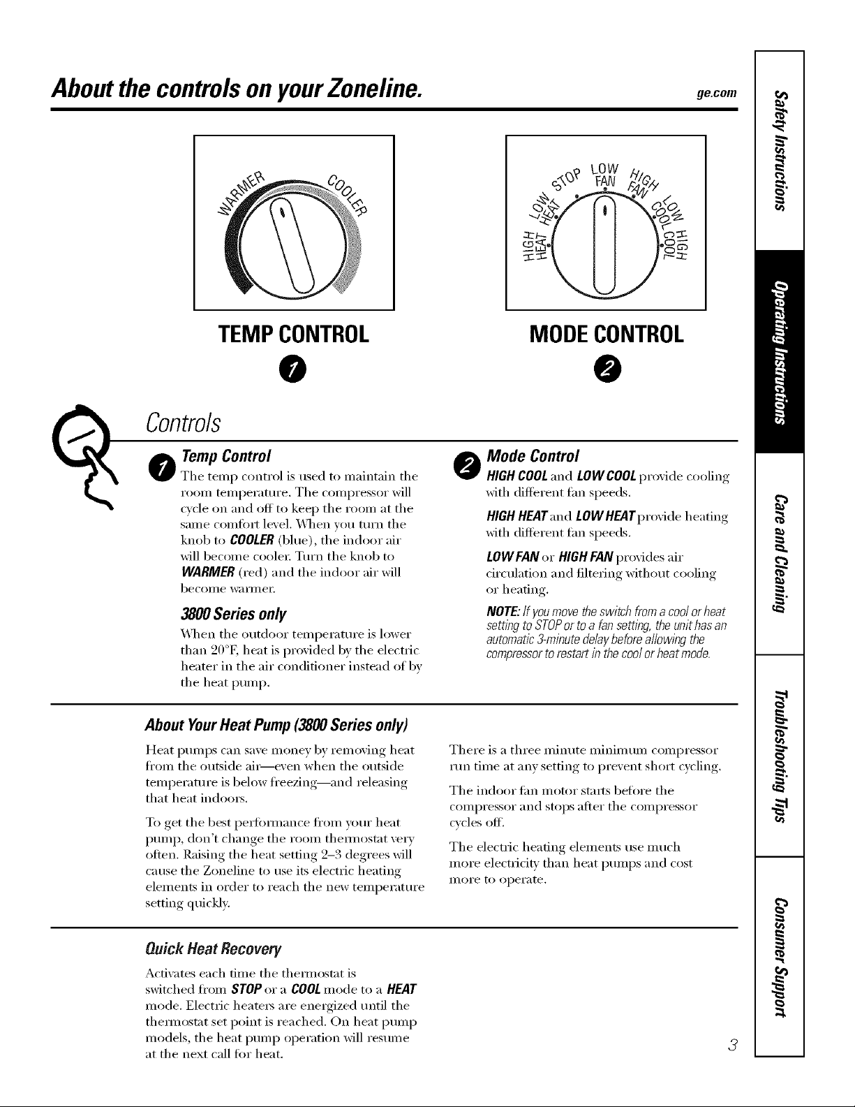
TempControl
The temp control is used to maintain the
Co trols
I'00111 telllpei'attli'e. The coi/li)i'essoi" will
c_cle on and off to kee I) the room at the
same comfort level. _]_en you tm'n the
knob to COOLER(blue), the indoor air
will become coole_: Tm'n the knob to
WARMER (red) and the indoor air will
become wai_nlei:
3900Series only
_]_en the outdoor temperatm'e is lower
than 90°E heat is provided b)' the electric
heater in the air conditioner insmad of bv
the heat I)ump.
About YourHeat Pump (3800 Series only)
Heat l)mnps can save money by removing heat
fl'om the outside ai_e\'en when the outside
temperature is below fl'eezing--and releasing
that heat indom_,
To get the best pex_bmmnce fl'om your heat
I)mnp, don't change the room them/ostat ve_T
often. Raising the heat setting 2-3 degrees will
cause the Zoneline to use its electric heating
elements in order to reach the new temperatm'e
setting quickly.
MODECONTROL
@
Mode Control
HIGH COOLand LOW COOLpr_vi(le cooling
with different tim speeds.
HIGHHEATand tOW HEATprovide heating
with different tim speeds.
LOWFAN or HIGH FAN provides air
circulation and filtering without cooling
or heating.
NOTE:If youmove the switch from a cool orheat
setting to STOPorto a fan setting, the unit hasan
automatic3-minute delaybefore a//owlbg the
compressortorestart in thecool or heat mode.
There is a three minute minimum compressor
run time at any setting to prevent short cycling.
The indoor tim motor stm*s beli)re the
compressor and stops after the compressor
cycles off.
The electric headng elements use much
more electricit_ than heat pmnps and cost
II/OI'e to operate.
Quick Heat Recovery
Activates each time the them_ostat is
switched fl'om STOP or a COOLmode U) a HEAT
mode. Electric heatex_ are energized until the
them_ostat set point is reached. On heat pump
models, the heat pump operation will resume
at the next call for heat.
3
Page 4
Otherfeaturesof yourZoneline.
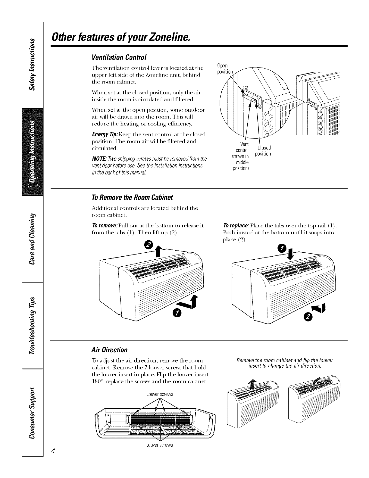
Ventilation Control
The xentilation control lexer is located at the
upper lett side of the Zoneline unit, behind
the room cabinet.
_,_q_en set at the closed position, onE' the air
inside the room is circulated and filtered.
X,_]_en set at the open position, some outdoor
air will be drawn into the room. This will
reduce the heating or cooling efficiency.
Energy Tip: Kee I) the vent control at the closed
position. The room air will be filtered and
circulated.
NOTE:Twoshiww screwsmustberemovedfromthe
ventdoorbeforeuse.Seethe/nstal/afionInstructions
in thebackofthismanual
ToRemovethe RoomCabinet
Additional controls are located behind the
I'OOIll cabinet.
To remove:Pull out at the bottom to release it
fl'om the tabs (l). Then lift up (_2).
Open
position
Vent
control Closed
(shownin position
middle
position)
To replace: Place the tabs oxer the top rail ( l ).
Push imvard at the bottom tmtil it snaps into
place (2).
Air Direction
To a(!iust the air direction, remove the room
cabinet. Remove the 7 louver screws that hold
the louver insert in place. Flip the louver insert
180°, replace the screws and the room cabinet.
Louverscrews
Louverscrews
4
Removethe room cabinet and flip the louver
insert to change the air direction.
Page 5
Auxiliary Controls onyour Zone/ine. ge.com
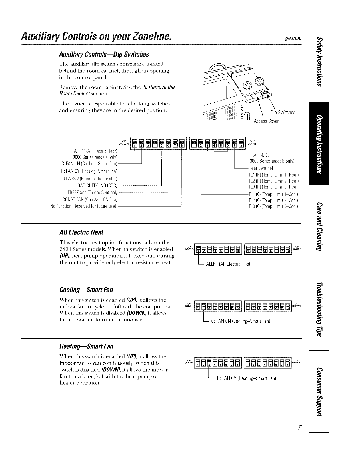
Auxiliary Controls--Dip Switches
The au_liary dip switch controls are located
behind the ro()m cabinet, through an opening
in the control panel.
Remove the room cabinet. See the To Remove the
Room Cabinet section.
The owner is responsible for checking switches
and ensuring they are in the desired position.
DipSwitches
Access Cover
ALLI2R(All Electric Heat)--
(3800Series models only)
C:FAN CN(Cooling-Smart Fan)
H:FAN CY(Heating-Smart Fan)
CLASS2(Remote Thermostat)
LOADSHEDDING(CDC)
FREEZSen (FreezeSentinel)
CONSTFAN(Constant ON Fan)
No Function(Reservedfor future use)
All Electric Heat
This electric heat option flmcfions only on the
3800 Series models. X,_q_enthis switch is enabled
(UP), heat pump operation is locked out, causiw,,
the unit to provide only electric resistance heat.
Cooling--Smart Fan
_Al_en this switch is enabled (UP), it allo_vs the
indoor lira to cycle on/offwith the compresso_:
\A]_en this switch is disabled (DOWN),it allows
the indoor tilIl to I'tln contintlOtlslv.
-- _ [--HEAT BOOST
(3800Series modelsonly)
I
--Heat Sentinel
TL1(H)(Temp.Limit 1-Heat)
TL2(H)(Temp.Limit 2-Heat)
TL3(H)(Temp.Limit 3-Heat)
TL1(C)(Temp.Limit 1-Cool)
TL2(C)(Temp.Limit 2-Cool)
TL3(C)(Temp.Limit 3-Co01)
oo%4maaaaaawl[BaaBaaaaloo%.
L ALLFR(All Electric Heat)
° "[B?BBBBBBBBBBBBB
C: FAN CN (Cooling-Smart Fan)
Heating--Smart Fan
\_l_en this switch is enabled (UP), it allo_vs the
indoor tim to run continuously. When this
switch is disabled (DOWN),it allo_:s the indoor
lira to cycle on/off with the heat pump or
heater opei'ation.
° °IBB BBBBBBBBBBBBB
L__ H: FAN CY (Heating-SmartPan)
Page 6
Auxi/iaq controlsonyourZoneline.
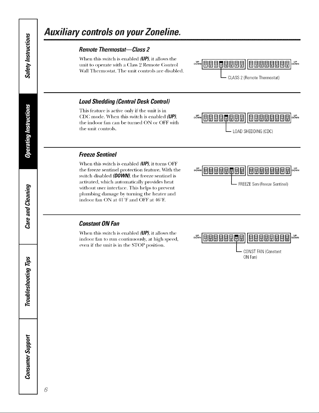
Remote Thermostat--Class 2
_._q_en this switch is enabled (UP}, it allows the
unit to operate with a Class 2 Remote Control
Wall Them_ostat. The trait controls are disabled.
LoadShedding(CentralDesk Control)
This featm'e is active only if the trait is in
CDC mode. When this switch is enabled (UP),
the indoor tim can be tin'ned ON or OFF with
the trait controls.
Freeze Sentinel
_._l_en this switch is enabled (UP), it turns OFF
the fl'eeze sentinel protection ieatm'e. With the
switch disabled (DOWN),the fl'eeze sentinel is
acti\_ted, which automatically provides heat
without user inte_ti_ce. This helps to prevent
plumbing damage by turning the heater and
indoor tim ON at 41°F and OFF at 46°E
°_'%BBBI_BBBBBBBBBBBB°_'%
L CLASS 2 (Remote Thermostat)
°_:"BBBB_BBB BBBBBBBB°_:"
L_ LOAD SHEDDING(CDC)
°_"[BBBBB@BBJBBBBBBBB °'%"
t FREEZESen(Freeze Sentinel)
Constant ON Fan
"_._q_enthis switch is enabled (UP),it allows the
indoor tim to run continuously at high speed,
exen if the trait is in the STOP position.
°_"BBBBBB@B BBBBBBBB °"%°
t DONST FAN(Constant
ON Fan)
Page 7
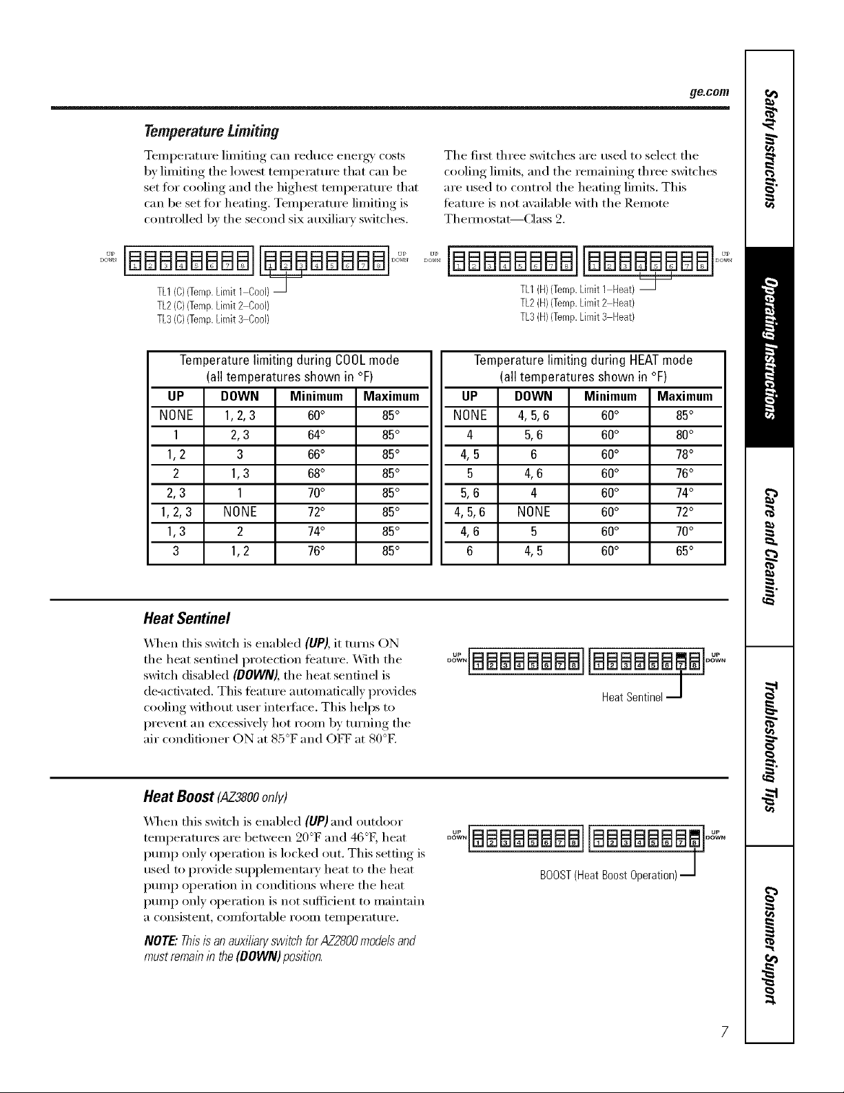
Temperature Limiting
Temperature limiting can reduce energy' costs
by limiting the lowest temperature that can be
set fl)r cooling and the highest temI)erature that
can be set fin" heating, Temperature limiting is
controlled by the second six au_liarv switches,
ge.com
The fit_t three switches are used to select tile
cooling limits, and the remaining three switches
are used to control the heating limits, This
teatm'e is not available with the Remote
Them_ostat--Class 2.
iBBBBBBBBi BBBBBBB
TL1/C)(Temp.Limit 1 Cool)"_'-
TL2(C)(Temp.Limit2 Cool)
TL3(C)(Temp.Limit3 Cool)
Temperature limiting during COOLmode
(all temperatures shown in °F)
UP DOWN Minimum Maximum
NONE 1,2,3 60° 85°
1 2,3 64° 85°
1,2 3 66° 85°
2 1,3 68° 85°
2,3 1 70° 85°
1,2,3 NONE 72° 85°
1,3 2 74° 85°
3 1,2 76° 85°
Heat Sentinel
_,_]/eil this switch is enabled (UP), it turns ON
the heat sentinel protection teatm'e. _,_]th the
switch disabled (DOWN), the heat sentinel is
de-actiw_ted. This teatm'e automatically provides
cooling without user intedhce. This helps to
prevent an excessively hot room by turning the
air conditioner ON at 85°F and OFF at 80°E
°°%iBBBBBBBBiIBBB
TL1(H)(Temp.Limit 1 Heat)
TL2(H)(Temp.Limit2 Heat)
TL3(H}(Temp.Limit3 Heat)
Temperature limiting during HEATmode
(all temperatures shown in °F)
UP DOWN Minimum Maximum
NONE 4, 5,6 60° 85°
4 5,6 60° 80°
4,5 6 60° 78°
5 4,6 60° 76°
5,6 4 60° 74°
4,5,6 NONE 60° 72°
4,6 5 60° 70°
6 4,5 60° 65°
oo%qaBBBBaBB]laaaaaaa,ale,,.
Heat Sentinel J
Heat Boost (AZ3800only)
_&]/en this switch is enabled (UP) and outdoor
teml)eratures are between 20°F and 46°E heat
pmnp only operation is locked out. This setting is
used to provide SUl)plementa_ T heat to tile heat
pmnp operation in conditions where tile heat
pmnp only operation is not sufficient to maintain
a consistent, coi//ti)rtable i'OOlil tei//l)ei'at/li'e.
NOTE."ThisisanauxilbryswitchforAZ2800modelsand
mustremabb the(DOWN)position.
BOOST(Heat Boost Operation) J
Page 8
Auxiliary controlsonyourZoneline.
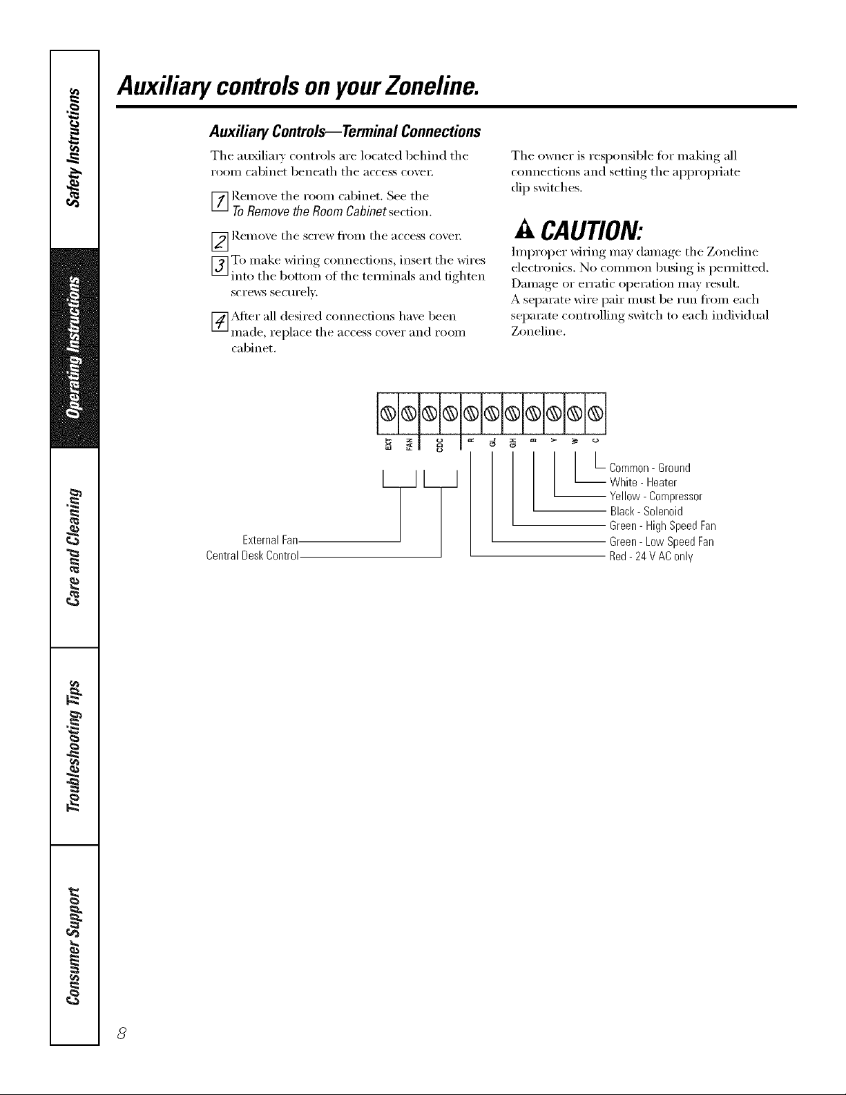
Auxiliary Controls--Terminal Connections
Tile auMlim_' controls are h)cated behind tile
rooiil cabinet beneath tile access coxei;
_] Remoxe tile room cabinet, See tile
ToRemove the Room Cabinet section.
_ Rei/loxe tile screw tl'Oill tile }l('('ess ('o_ei;
To make wiring, connections, insert tile wires
] ) ) 0 0 S o"
inU tile b( tt m f tile temfinal: and d_hten
screws securelx.
[_Mter all desired cmmections have been
Illade, replace tile access coxei" }lll(l rooi//
cabinet.
The owner is responsible fi)r making all
c(mnections and setting tile appropriate
dip switches.
A CAUTION:
hnproper wiring may damage tile Zoneline
electronics. No common busing is pemfitted.
Damage or erratic operation may result.
A separate wire pair illtlst be rtm from each
separate controlling switch to each individual
Zoneline.
ExternalFan.
CentralDeskControl
{a
aa
I L- Common-Ground
_ White - Heater
Yellow- Compressor
Black-Solenoid
Green-HighSpeedFan
Green- LowSpeedFan
Red-24 V AConly
8
Page 9
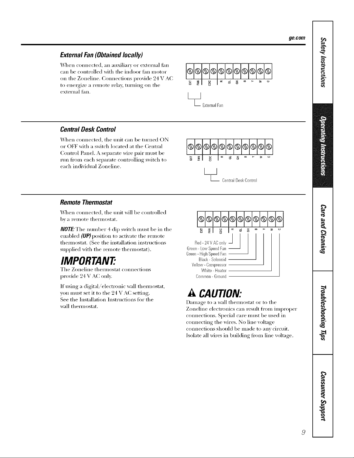
External Fan(Obtainedlocally)
_,_]/eIl connected, an auxiliary or external tim
can be controlled with the indoor tim motor
on the Zoneline. (:om_ecfions provide 24 V AC
to energize a remote relay, tm'ning on the
external tim.
Central Desk Control
_,_l_en connected, the unit can be tin'ned ON
or OFF with a switch located at the Central
Control Panel, A separate wire pair must be
run fl'om each separate controlling switch to
each individual Zoneline.
Remote Thermostat
ge.com
[__1
TIExterna] Fan
@@@@@@@@@@@
o
LmJ
L CentralDeskCentre[
_,_q_en connected, the unit _fill be controlled
b _, a i'eillote thermostat,
NOTE."The number 4 dip switch must be in the
enabled (UP) position to activate the remote
them_ostat. (See the installation instructions
supplied with the remote them_ostat).
IMPORTAN7
The Zoneline them_ostat connections
provide 24 V AC only:
If using a digital/electronic wall them/ostat,
vou must set it to the 24 V A(: setting.
See the Installation Instrtlctions for the
wall them_ostat.
o
/
Red- 24 VAC only /
Green-Low SpeedFan --
Green-HighSpeedFan --
Black- Solenoid
Yellow- Compressor
White - Heater
Common-Ground
A CAUTION:
Damage to a wall them_ostat or m the
Zoneline electronics can result fl'om improper
connections. Spedal care must be used in
com_ecting the wires. No line w)ltage
com_ections should be made to any circuit.
Isolate all wires in building fi'om line wdtage.
Page 10

Careand cleaning.
Room Cabinet and Case
Turn the Zoneline otI and disconnect the
power supply:
OutdoorCoils
The coils on the outdoor side of the Zoneline
should be checked regularly. If the)' are clogged
with dirt or soot, they may be protessionally
steanl cleaned, a service a\:filable through yore"
(;E selMce outlet. You will need to remove the
unit to inspect the coils because the dirt
buildup occm_ on the inside.
To clean, use water and a mild detergent.
Do not use bleach or abrasives. Some commercial
cleane_ may damage the plastic parts.
Coils
Grille
Cleat?the outside coils regularly.
Base Pan
In some installations, dirt or other debris may be
blown into the unit fl'om the outside and settle in
the base pan (the bottom of the unit).
Ventilation Filter
If the ventdoor isopen,clean the ventfilter twice a year
or as required
TurntheZonehbeoff beforecleaning
Toremove the vent filter:
• Remove the room cabinet. See the ToRemove
the Room Cabinet section.
• Remove the tOt:u"screws securing the unit
flanges to the case.
• Slide the unit fl'om the wall case.
• Grasp the vent filter tab and pull the filter out
by sliding it to the right.
In some areas ot the United States, a "gelqike" or
"slime-like" stlbstance ill}iV be seen in the base l);In.
Check it periodically and clean, if necessary:
Toclean the vent filter:
• P.un water through the filter fi'om the
back side.
• D_y thoroughly before replacing.
10
Page 11

Tomaintain optimum performance, clean the filters at least every 30 days.
Air Filters
m_
Toremove the air filters:
ge.com
2Air filters
Pullup
Dirly filter--Needs cleanflTg Clogged filter--Greatly
reduces cooling, heating
and airflow.
Turnthe Zoneline offbefore cleaning.
The most iml)ortant thing you can do to
maintain the Zoneline is to clean the filter
at least every 30 days. Clogged filte_3 reduce
cooling, heating and air flow.
Keeping these filters clean will:
• Decrease cost of operation.
• Save energy:
• Prevent clogged heat exchanger coils.
• Reduce the risk of prematm'e component
fifilm'e.
Toclean the air filters:
• Vacuum off' the heavv soil.
•Rtm water through the filte_s fl'om the
back side.
• D_T thoroughly befiwe replacing.
/VOTE:Theair filte_ are interchangeable
and will fit in either the right or left side.
Toreplace the air filters:
Pushdown
CAUtiON: Oonot operate the
Zonelinewithout the filters inplace.Ira filter
becomestorn or damaged,it should bereplaced
immediately.
Operating without the filte_s in place or with
damaged filte_ will allow dirt and dust to reach
the indoor coil and reduce the cooling, heating,
airflow and efficiency of the refit.
Replacement filtex_ are awfilable fl'om yore"
salesperson, GE dealer, GE Service and Parts
Center or authorized Customer Care '_sec,'icers.
11
Page 12

Installation
Zoneline Air
Instructions
Conditioners
Questions?Call 800.GE.CARES(800.432.2737)orVisitour Website at: ge.com I
BEFORE YOU BEGIN
Read these instructions completely and carefully.
• IMPORTANT - S_,,ethe_e
inst_ uctions for local inspector's use.
• IMPORTANT - Obse,,e_,,
governing codes and ordinances.
• Note to Installer - Be sure to leave these
instructions with the owner
• Note to Owner - Keep these instructions tor
fllttu'e reterence.
° Proper installation is the responsibility of the
installer,
• Product taihu'e clue to improper installation is not
covered trader the _arrantv.
TOOLS YOU WILL NEED
Phillipsscrewdriver
IMPORTANT ELECTRICAL
SAFETY--READ CAREFULLY
_k CAUTION:
• Follow the National Electrical Code (NEC) or local
codes and ordinances.
• For personal safety, this Zoneline must be properly
grounded.
• Protective devices (fuses or circuit breakers)
acceptable for Zoneline installations are specified
on the nameplate of each unit.
• Do not use m_ extension cord with this refit.
Aluminum building wiring may present special
problems--consult a qualified electricim_.
When the unit is in the OFF position, there is
still voltage to the electrical controls.
Discmmect the power to the unit before
servicing by:
1 Removing the power cord (if it has one) from
the wall receptacle.
OR
2 Removing the branch circuit fuses or turning
the circuit breakers off at the panel.
ZONELINE COMPONENTS
Exteriorgrille/louver**J
Wallcase*f--_
Shipped with the Zoneline unit
Checkthe "Essential Elements" list on the unit
m cabinet*
F Zonelineunit
-Power supplykit....
12
Page 13

Installation Instructions
REPLACING AN EXISTING UNIT?
Check the "Essential
Elements" label for
importantinformation.
Use the correct wall case
This unit is designed to be installed in a GE plastic or
insulated metal wall case. This minimizes condensation
fl'(nn fimning on the room side of the case.
If the current wall case is not insulated, you can reduce
the possibili_' of condensation fimning by installing
insulation kit I_L_K901 i,, a\:filable where you purchased
the unit.
NOTE: There are several extra holes in the unit side
flanges t0r installation in wall cases other than GE.
To avoid damaging the flange insulation, the installer
should use an awl or other shaq) tool to puncture the
insulation in the appropriate holes beiore installing
the attachment screws.
Replacing a ducted unit
New ducted installation:
If this unit is to be installed in a new ducted application
using a duct adapter kit, the kit must be installed before
the unit is placed in the wall case. The installation
instructions are packed with the kit.
plate
Existing ducted installation:
Replacement of an existing ducted unit may require
different components. Request this intimnation ti'otu
your sales representative.
• Replacing 230/208 volt turiN:
See page 14.
• Replacing 265 volt turiN:
See pages 15 and 16.
Use the correct outdoor grille
You should use the outdoor grilles shown on the
"Essential Elements" label on the top of the unit.
• If an existing grille is not replaced, capaci D' and
efficiency will be reduced and the unit tuav tail to
operate properly or tifil prematurely. A deflector kit,
I_L_K40, tua)" be used with grilles that were not
designed t0r your new GE Zonelines. The IL_K40
contains air deflect(ns and gaskets that tuount to the
unit to direct the hot exhaust air away fl'otu the air
intake to allow the unit to fltuction properly. The
grille m tlSt have a 65% minituutu fl'ee area.
• Any vertical deflectors in the existing rear grille should
be retuoved to decrease condenser air recirculation
that can cause the trait to "short-cycle" and lead
to pi'eli/attli'e COlilponent tifihu'e.
Use the correct power cord
I,ocal codes tua)' require the use of arc fault or
leakage current detection devices on 230/208 volt
installations.
13
Page 14

Installation Instructions
230/208 VOLT ELECTRICAL CONNECTION OPTIONS
HOW TO CONNECT
1 Remove the roon/ cabinet.
2 Connect to electrical power.
3 Review the following steps fi)r applicable supply
voltages.
4 Reinstall the ro()m cabinet.
POWER CORD
CONNECTION
A power supply kit must be used to supply power to fl_e
Zoneline unit. The apl)ropfiate kit is determined b)' the
voltage, the means of electrical connection and the
amperage ol the branch drcuit.
Power supply kit
Connections of 208 oi 230 xolt ciicuits max be with a
power supply kit or a junction box kit.
All wiring, including installation of the receptacle,
must be in accordance with the NEC and local codes,
ordinances and regulations, i,ocal codes may require
the use of an arc tmllt or leakage current detection
device on the power cord. Be sure to select the
correct cord ti)r your installation.
Power cords may include an arc fault interruption or
a leakage current detection interruption device. A
test mad reset button is provided on the plug case or
the inline case. The device should be tested on a
periodic basis by first pressing the TEST button and
then the RESET button. If the TEST button does
not trip or if the RESET button will not stay engaged,
discontinue use of the Zonelhae and contact a
qualified service technician.
ELECTRICAL SUBBASE
CONNECTION
230/208 xolt models ma) be installed using one of
the fi)llowing electrical subbases:
Branch Circuit and
UnitAmperage Bating
15
20
3O
*Noi approved I6r use on 7000 BTU models.
Electrical subbases provide an enclosure fi)r direct
connection or enclosed receptacles. The subbase kit
includes the power cord.
The instructions provided with the selected sul)l)ase kit
must be carefilllv t()llowed. It is the responsibiliQ' of the
installer to ensure the connection of components is
done in accordance with these instructions and all
electrical codes.
Proper GE
Subbase Kit
]L_K204D15P
],L_IC,204L)20 P
],L_K204L) 30P*
© © @
Tandem Perpendicular Large Tandem
15Amp. 20 Amp. 30Amp.
230/208volt receptacle configuration.
Branch Circuit and Proper GEPower Cord
UnitAmperage Bating with LCDIDevice
15 ]L_K3153
20 I,L_K3203
30 ]L_K3303*
':No( at)proxe(t tor use on 7000 BTU too(Ms.
DIRECT CONNECTION
Order the following Kit for 230/208 xolt direct
connection as required:
Branch Circuitand Power Supply Power
UnitAmperage Bating Accessory SupplyKit
15 IL_K4002A I_&K4157
20 IL_K4002A IL_K4207
30 I,L_K4002A I,L_K4307
Skip to the "MAKE EI,ECTlllCAI, CONNECTION TO
THE UNIT" section.
Page 15

Installation Instructions
265 VOLT ELECTRICAL CONNECTION OPTIONS
./k WARNING:
Connection of this 265 V AC product to a branch circuit
MUST be done by direct connection in accordance with
the National Electrical Code. Plugging this unit into a
building mounted exposed receptacle is not pemfitted
bv code,
These models must be installed using the appropriate
GE power supply kit tor the branch circuit amperage
and the electrical resistance heater wattage desired.
Use the PO_4'ER CONNECTION CHART on page 17
to detemfine the correct kit required, One of the
following installation methods (A or B) I//tlSt be used.
A. FOR SUBBASE INSTALLATION
Electrical subbase !dts are available to provide a flexible
enclos/li'e Ik)i" direct connection.
Branch Circuit and Proper GE Power
UnitAmperage Bating Subbase Kit SupplyKit
15 ILML204E 15 I_M(5172
20 ILML204E20 I_M(5202
B. FOR DIRECT CONNECT
INSTALLATION
If an electrical subbase is not used, direct connection to
branch circuit wiring inside the provided junction box
must be done in accordance with the tollowing steps.
Order the t011owing Kit tiw 265 volt direct connection as
required:
Branch Circuitand Power
UnitAmperage Rating SupplyKit
15 1_M(5157
20 1_I(5207
30 1_K5307
Proceed to the "MAIZE EI,ECTRICM, CONNECTION
TO THE UNIT" section.
30 IL_K204E30 ILM(5302
The instructions provided with the selected subbase kit
must be carelifllv tollowed. It is the responsibility of the
installer to ensure the connection of components is
done in accordance with these instructions and all
electrical codes.
15
Page 16

Installation Instructions
MAKE ELECTRICAL CONNECTION TO THE UNIT
[] REMOVE JUNCTION BOX
1 Remo_e the junction box cover 17}removing the
fl'ont two screws,
2 Remove thejmTction box b) removing the top and
bottom rear screws. Note how the tabs on the lower
left side of the junction box ser_v to t7o1(t the skte in
place. This will help when flTe box is being reinstalled.
Unit connector
Junction Junction
boxcover box
[] CONNECT THE CORDSET
Plug the connector, provided in the Direct Connect
ICdt,flfll) into place in the unit mating coililectot'.
Be sure the locking tabs at the sides are engaged.
C0nnector
disconnect inside tbejmTction box.
I NOTE: Order Kit RAK4002C_& to enable a quick
[] ATTACH CONDUIT
1 Use the romM knockout at the bottom of the
j mwtion box to attach conduit coming from tim
branch circuit. Remove tim knockout, attach the
conduit and bring wires into the junction box.
I,eave 6" of wire fl'ee at the end ot the conduit
to allow coiTiTectioiTs to be made,
2 If a fuse and flBebolder are to be used, the
knockout at the top of the box is tot motmting
a Buss Fuseboldet: Be sm'e the fuse and fusebolder
are of the same rating as the branch circuit.
I,eadwires at the fuse can be either soldered in
place or attached using UIAisted 1/4" timmle
(receptacle) crimp connectms.
[] REINSTALL JUNCTION BOX
• Reinstall tbe.jmTction box by engaging tim left tabs
on the lower right tace of the unit, aligning the
screw holes at the top and bottom and driving the
two screws tmtil secure. Be sure that all wire leads
are inside the box and not pinched between the box
and the refit. The green insulated ground wire from
the unit MUSTbe comTected to the branch drcuit
grotmd wire.
Make all wire comTections by using al)propriate
UIAisted electrical comTectms and techniques
I
(black to black, white to white and green to green).
L_ .....
[] REINSTALL JUNCTION BOX COVER
1 Carefully tuck all wires and comTections back inside
thejmTction box. Be sure there are 17o loose
connections or stray tminsulated wires exposed.
2 Place thejunc6on box cover in place. Replace the
two sct'e_vs removed earlier atTd figbtei7 securely.
16
Page 17

Installation Instructions
POWER CONNECTION CHART
Power Cord Connections
230/208 Volt
Power Supply Kits
with Current Leakage
Detection Device
RAK3153
RAK3203
RAK3303*
230/208 Volt Heater Wattage
Power Supply Kits @ 230/208 Volts Ch-cuit Protective Device
RAK4157 2,55 K_'/2.09 K_' 15 Amp Time-Delay Fuse or Breaker
RAK4207 3,45 KW/2.82 KW 20 Amp Time-Delay Fuse or Breaker
RAK4307 5.00 KW/4.10 I_A,V 30 Amp Time-Delay Fuse or Breaker
265 Volt Heater Wattage
Power Supply Kits @ 265 Volts Ch-cuit Protective Device
RAKS172 2.55 K_' 15 Amp Time-Delay Fuse or Breaker
RAK5202 3.45 KW 20 Amp Time-Delay Fuse or Breaker
RAK5302* 5.00 K_4' 30 Amp Time-Delay [_tlse or Breaker
* Not approved ti)r use on 7000 BTUH units.
WaUPlug
Configuration
Tandem
Perpendicular
I,arge TmMem
Circuit Protective Device @ 230/208 Volts
20 Amp Time-DelaY' Fuse or Breaker
15 Mnp Time-Delax Fuse or Breaker
30 Mnp Time-Dela_ Fuse or Breaker
Direct Connections
Heater Wattage
2.55/2.09 K\,_
• .4a/2.82 K\,_
5.00/4.10 14_
17
Page 18

installation instructions
INSTALLING THE ZONELINE
[] iNSTALL THE WALL CASE AND
EXTERIOR GRILLE
The I_B71 series or IL_B77 _<dl case must be
properl) installed per instructions packed with
tile case.
* Remoxe tile conugated stittbner and tile outdoor
protectix e panel, Llse tile slit in tile outdoor panel
as a handhokl and push out.
Pro
panel
Stiffenel
• Install the extel_ior grille from tile room side
following instructions packed with tile gl-ille.
Insulated Wall Case
This unit is designed to be installed in a GE plastic
or an insulated steel wall case. This minimizes
condesisation fix)l// iksIs//illg (511 tile 1"(5(5I// skle ot
tile case.
The ]gkg71 selJes wall cases are insulated. Insulation
kit lgM_5,)01I, is ax;filable tbr use with lgkg77 or
e_sting uninsulated wall cases when needed.
NOTE: For installation with a subbase or duct adapte_;
see the instructions packed with those kits.
[] PREPARE THE UNIT
• Carefully remove shipping tape and loam shipping
blocks fl'om tile room cabinet, compressor and
vent do(m There may be multiple blocks and pieces
ot shipping tape that need to be reinoved.
Shippingtape
(Locationsmayvary)
• Remove tile room cabinet b)pulling it out at tile
bottom to release it (l), then lift it up to clear tile
rail along tile trait top (2).
• If vent door is t(5 be operational, rem(sve shipping
screws ti'om tile fl'(mt side of tile xent d(55)_; if"present.
18
Removetwo
shippingscrews
Page 19

Installation Instructions
[] iNSTALL THE UNiT iNTO THE
WALL CASE
Slide the unit into the wall case and secure with ibm"
scre_s through the unit flange holes.
NOTE: There are several extra holes in the trait side
flanges t0r installation in wall cases other than GE.
To avoid damaging the flange insulation, the installer
should use an awl or other shmp tool to puncture the
insulation in the appropriate holes before installing
the attachment screws.
[] REPLACE THE ROOM CABINET
Reinstall the room cabinet b) hooking the top oxer
the rail ahmg the unit top (l), then I_ushing, it in at
the bottom (2).
19
Page 20

Installation Instructions
OPTIONAL--DRAIN KIT INSTALLATION
Dry Air 25 Series models are designed to improve dehumidification by 25%. Since more moisture will be removed from
the air, there is a greater possibility that water will drip from the wall case thml with a standard mlit. To prevent this water
from dripping onto external building walls, we recommend the use of RAD10 Drain Kit.
External Drain
See the Installation ]nstHwtions
in the RADIO kit.
Internal Drain
See the Installation Instructions
in the RAD 10 kit.
Squaredrainholes
"_ "_ _._ Type"A" screwfor metalcaseor
1/2" O.D.draintube / 4:_'_'" :'_'_
Neoprenespongegasket /
Steelmountingplate
Type"B"screwfor moldedcase
/
¢
Alternate:
6"long, 1/2" O.D. straight
coppertube
©
Squaredrainholes
"_ -_ _-_ Type"A" screwfor metalcaseor
Neoprenespongegasket /
Steelmountingplate
Type"B"screwfor moldedcase
2O
,I
Page 21

Beforeyou carl forservice.., ge.com
TrOubleshooting -tips
Save time and money! Review the charts on the following
ages first and you may not need to call for service.
Problem Possible Causes What To Do
Zoneline does The unit is * Make sure the Zoneline plug is pushed completely
notstart unplugged, into the outlet.
The power cord is not * Rem_we the room cabinet and make sure that the
firmly attached, yellow, connector on the end ot the power cord is
firefly engaged.
The fuse is blown/circttit • Check the house fllse/drcuit breaker box and replace
breaker is tripped, the fllse or reset the breaker:
The unit is waiting for • This is nomml. The Zoneline will start again afier
the compressor overload it resets.
protector to reset,
Power failure.
• If power fifihu'e occm_, set the m ode control to STOP.
When power is restored, set the mode control to the
desired setting.
• There is a protective time delay (up to 3 minutes) to
prevent trii)ping ot the compressor overload. For this
reason, the unit may not start nomml heating or cooling
ti)r 3 minutes al*er it is tin'ned back on.
The current interrupter
device is tripped.
Zoneline does not cool Indoor airflow • Make sure there are no curtains, blinds or flu'niture
or heat as it should is restricted, blocking the fl'ont el the Zoneline.
Outdoor airflow is
restricted or recirctdated.
The temp control may • Tm'n the control to a lower or higher setting.
not be set properly, NOTE:Thetemperaturel/mitermaybe bruitingthetemperaturerange.
The air filter is dirty. • Clean the filter at least e\'e_y 30 days.
The room may have • When the Zoneline is fi_t turned on vou need to
been hot or cold. allow time tin" the room to cool down or wama up.
Outdoor air is • Set the vent control to the closed position.
entering the room.
Burning odor at the start
of heating operation
Dust is on the surface
of the heating element.
• Press the RESETbutton located on the power cord i)lug
or the box near the plug.
• If the RESETbutton will not stay engaged, discontinue ttse
of the Zoneline and contact a qt_dified sexaice technician.
• Make sm'e the rear grille is not restricted. This can
cause the trait to cycle off due to the compressor
overload l)rotectoi:
• Outdoor grille must have a minimum of 65% fl'ee area.
Non-OE grilles may be too restrictive for i)roper
pertbmmnce. Consult p)tu" salesperson tot assistance.
See the Operating Instructions section.
• This can cause a "burning" odor at the beginning of
the heating operation. This odor should quickly fade.
21
Page 22

Beforeyoucall forservice...
Problem Possible Causes What To Do
The air is notalwags The heat pump is not * Tiffs is normal. Tile he_=t pump will produce wm'm air
cool or hot during producing hot air. but not _s hot as air produced _dlen the higher-cost
operation electric beat is used.
The fan switches may be
set at continuous fan.
O
Tiffs causes tile tim to blow room temperature air
even when the COlllpressor or he:lter cycles elf.
Tile continuous air movement provides better
overall temperature control ill tile cool mode.
There is one switch fl_r cooling and one switch
fi)r beating.
Theair doesnotfeel
warmenoughduring
heatingoperation
The unit is not The fan dip switch may * See the Auxiliary Controls section.
blowing out air be set to CYCLE.
The electric heating
feature does not work
The heat pump alone
produces air that feels
cooler than desired.
The power cord is not
firmly attached.
Use tile Electric Heat ()ption, Tiffs turns off tile
heat pmnp and warms with electric heat only,
NOTE: Uso of this option will result it) incroasod onorgy
consumption.
o Remove tile romn cabinet and make sure that tile
yellow connector on tile end of tile power cord is
firmly engaged.
22
Page 23

Things thatare normal ge.com
Normal Operating Sounds
Y/u may hear a pinging noise caused by water being
PING! POP:
' I
" @
picked up and thrown against tile condenser on
rainy da_:s or when tile humidity is high. This design
feature helps remo\ e moisture and improve
efficiency.
"CLICK"
DRIP
6
WKIB!
You may hear relays click xdlen tile controls c) cle
on and off or are a@usted to change tile roon/
temperature.
\'\Citer x_ill collect in tile base pan during high
humidi_ or on raim daxs. Tile water ma) oxelflow
and drip fl'om tile outdoor side of tile unit.
Tile indoor tim runs continuously when tile unit is
operating in tile cooling mode, unless tile fire switch
behind tile room cabinet is set at iim cycle (up).
This will cause tile tim to cycle on and off with tile
COlllpFessol2 _/()ll may also Ileal" a _itll IlOlSe stop
and start.
You may notice a few minutes delay ill starting if you
tlT to restart tile Zoneline too soon after tm'ning it
off or if you ac!iust tile thermostat fight Jilter tile
con_p_essor has shut ore This is due to a built-in
restnI_ protector fi/r tile compressor that causes
a 3-minute delay.
Dm_ing tile defl'ost cycle, both indoor and o_.ltdo(n"
rims stop and tile compressor will operate in tile
cooling mode to remove fl'ost _i'om tile outdoor coil.
_Mter defl'ost, tile unit will restart ill electric heat to
quickly warm tile room to tile desired comfort le;vl.
COMPRESSOR
PROTECTION
To protect tile compressor and prex ent short
cycling, tile unit is designed to run fi)r a minimum
(/_ _4IlIinlltes atier tile c(}l//press(lF starts at ally
thermostat setting.
23
Page 24

NOteS_
r_
24
Page 25

Please place in envelope and mail to:
General Electric Company
Warranty Registration Department
P.O. Box 32150
Louisville, KY 40232-2150
,_ Ct/t hel-e
25
Page 26

Consumer Product Ownership Registration
Deal Customer:
Thank you for purchasing our product and thank you for placing your confidence in us.
V(e are proud to hme you as a customer'.
Follow these three steps to protect your new appliance investment:
Complete and mail
yollr C oils urller
Product Ownership
Registration today.
ttavc the peace ot
mind of knowing w_
call (olltact VOll ill
the unlikely _vent of a
satbty modification.
.\tier mailing the
registration below,
store this docmnent
in a satb place. It
contains intonnation
you will need should
loll reqtlire service.
Our service number is
800.GE.CARES
(800.432.2737).
Model Number Serial Number
,,I I,,
Important: If you did not get a registration card with your
product, detach and return the form below to
ensure that your product is registered, or register
online at ge.com.
Consumer Product Ownership Registration
Read your Owner's
Manual carefifllv
It will help you
operate follr llew
appliance properly.
, I
,_,,_ Cut here
I,,,,,, , , , , , I I , , , , , ,
M*: Ms. Mrs. Miss
Firsl ] ] Last
Name I I I I I I I I I Nam_ I I I I I I I I I I I I
Stl-eet
A( _ ress I I I I I I I I I I I I I I I I I I I I I I I
Apt. # I I
City [
[)ale l)lac(_(l
In [Jst: III
Month
0
I I I I I I l E-mailAddr<ss*
I I I I I I I I I I
I)ay ] i [ "l_ar ] I ]
GE Consumer & Industrial
Appliances
General Electric Compong
Louisville, KY 40225
ge.com
Model Number Serial Number
, , I
Phone
Nt/llll)er ]
* Please provide }_mr e-lnail address to receive, via eqnail, discounts, _,pecial otlbl:, and other
important communicalions from GE Appliances ((;1_\).
Check here if _11 do not want to receive conmmnications t]-_)ln(;EA's carcfiflly selected
partner,,.
FAILURI{ TO COMPI_ETE AND RETI RN Tt tlS CARI) DOES NOT DIMINISII h_)[ 7R
W.\I_LKN'IY RIGt ITS.
For more information about G1LVs privacy and data usage polio; go to ge.com and (:lick on
"Pri_acy Poli_y" or call 800.626.2224.
Stare I I [ Code I I
,, II,, II ,
Zip ]
26
I
I
Page 27

Zoneline Warranty.
All warranty service provided by our Factory Service Centers,
or an authorized Customer Care®technician. Toschedule service,
on-line, 24 hours a day, vis# us at ge.com, or call 800.GE.CARES
(800.432.2737).Forservice in Canada, call 1.800.361.3400.Pleasehave
serial number and model number available when calling for service.
For The Period Of."
OneYear
Fromthedate of the
originalpurchase
Five Years
Fromthedate of the
originalpurchase
Five Years
Fromthedate of the
originalpurchase
GEWill Replace:
Anypart ot the Zoneline which tifils due to a detect in materials or wox'knmnship. During this
limited one-year warranty, GE will also provide, free ofcharge,all labor and related service to
replace the def_'cti\'e part,
Any part of the sealed refrigerating system (the compressox; condensex; evaporator and all
connecting robing) which fhils due to a (lefect in materials or workmanship. During this
four-year limited additional warranty, GE will also i)r(Mde, free of charge, all labor and
related service to replace the defective part.
For the second through the fifth yearfl.om the date of original purchase, GE will replace
certain parts that tifil due to a defect in materials or wor!unanship. Parts covered are tim
moto_, switches, them_osmts, heate_; heater I)rotecto_, compressor overload, solenoids,
circuit boards, au_liary controls, themfisto_, ti'ost controls, ICR pump, cal)acito_, \m_sto_
and indoor 1)lower bearing. During this four-year limited additional warranty, you will be
responsible tot }liiVlabor or on-site service costs.
What GE Will Not Cover:
Staple your receipt here.
Proofof the original purchase
date is needed to obtain service
under the warranty
• Service trips to your site to teach you how to use
the product.
• Improper installation, delivery or ma'_mtenm_ce.
If you have an h_stallation problem, or if the air
conditioner is of hnproper cooling capacity for the
intended use, contact your dealer or installer. You axe
responsible for providing adequate electrical
comiecth_g facilities.
• In commercial locations, labor necessary to move the
unit to a location where it is accessible for service by
ml hldJvidual tectuficim_.
• FaJhtre or dmnage resulting from corrosion due to
hlstaJlation in an enviromnent containing corrosive
chemicals.
Warranty.Any implied warranties, iucludiug the implied warranties of merchantability or fituess for a particular purpose,
I XCLUSION OFIMPLIED WARRANTIES--Your sole and exclusive remedy isproduct repa# as provided in this Lim#ed
are limited to one year or the shortestperiod allowed by law.
• Replacement of fuses or resetting of circuit breakers.
• Failure of the product resulting from modifications
to the product or due to tmreasouable use, including
failure to provide reasonable and necessary maintenance.
• Failure or dmnage resuith_g from corrosion due to
hlstaJlation in a coastal enviromnent, except for models
lreated with special factory-applied m_ti-corrosion
protection as designated in the model number.
• Damage to product caused by improper power supply
voltage, accident, tin'e, floods or acts of God.
• Incidental or consequential dmnage to personal property
caused by possible defects with this air conditioner.
• Damage caused after delivery.
• Product not accessible to provide required service.
This warranty is extended to the original purchaser and any succeeding owner for products purchased for use
within the USA and Canada. If the product is located in an area where service by a GEAuthorized Servicer is
not available, you may be responsible for a trip charge or you may be required to bring the product to an
Authorized GE Service location for service. In Alaska, the warranty excludes the cost of shipping or service
calls to your site.
Some states or provinces do not aflow the exclusion or limitation of incidental or consequential damages. This
warranty gives you specific legal rights, and you may also have other rights which varyfrom state to state or
province to province. Toknow what your legal rights are, consult your local, state or provincial consumer
affairs office or your state's Attorney General.
Warrantor: General Electric Company. Louisville, KY 40225
27
Page 28

ConsumerSupport.
Haxe a question or need assistance with your appliance? Try the (;E Appliances _4'ebsite 24 hom_ a day
"J gEAppliancesWebsite ge.com
any day of the xear'. For greater comenience and taster service, you can now download Owner's Manuals,
_, order parts or exen schedule ser',ice on-line.
ScheduleService
Expert (;E repair setsice is only one step away fl'om xour door Get on-line and schedule your set\ice at
your, con;enience 24 hom_ am {lax of the xear! Or ('all 800.(;E.(_ARES (800.432.2737) during nom]al
business horn's.
ge.com
RealLifeDesignStudio ge.com
GE supports the Universal Design concept--products, services and enviromnents that can be used by
people of all ages, sizes and capabilities. _\'e recognize the need to design fi)r a wide range of physical and
mental abilities and impaim_ents. For details of GE's Universal Design applications, including kitchen
design ideas tot people with disabilities, check out our X,Vebsim today. For the headng impaired, please call
800.TDD.GEAC (800.833.4322).
PartsandAccessories
Individuals qualified to service their own appliances can have parts or accessories sent directly to their
homes (VISA, MasterCard and Discover cards are accepted). Order on-line today, 24 horn's every day or
by phone at 800.626.2002 dining nomml business hom_.
Instructions contained in this manual cover procedures to be performed by any user. Other servicing generally
should be referred to qualified service personnel. Cautionmust be exercised, since improper servicing may cause
unsafe operation.
ge.com
ContactUs
If you are not satisfied with the service w)u receive fl'om GE, contact us on our X&'ebsite with all the details
including yore" phone IltlI/lbeI; or wlJte to: General Manage_; Custolner Relations
GE Appliances, Appliance Park
I,ouisville, KY 40225
Register your new applimlce on-line---at your €onvellience[ Timelx, [)rodtlct registrati(, m will allow for
, enhanced communication and prompt service under the terms of your warranty, should the need arise.
l RegisterYourApplbnce
You max also mail in the pre-pfinted registration card included in the packing material, or detach and
use the tOm_ in this Owner's Manual.
ge.com
ge.com
Printed in China
 Loading...