

Page 1
Models: AVM14 AVM22
AVM15 AVM24
AVM18
Air Conditioner
Owner’s Manual
Important Safety Information
Operating Instructions
The Controls on Your Air Conditioner
Care of Product
Installation Instructions
Important Electrical Safety
Window Installation
Through-the-Wall Installation
Helpful Information
Things That Are Normal
3
4
7
16
If Something Goes Wrong
Before You Call For Service
GE Service Numbers
Warranty
GE Answer Center
®
800.626.2000
GE Appliances
17
Page 2
Welcome
Welcome to the GE family. We’re
proud of our quality products and
we believe in dependable service.
You’ll see it in this easy-to-use
manual and you’ll hear it in the
friendly voices of our customer
service department.
Best of all, you’ll experience
these values each time you enjoy
the comfort of your air conditioner.
That’s important, because your
new air conditioner will be part of
your family for a long time.
Start Here!
Before using
your air
conditioner
Staple your receipt to the inside back
cover of this manual.
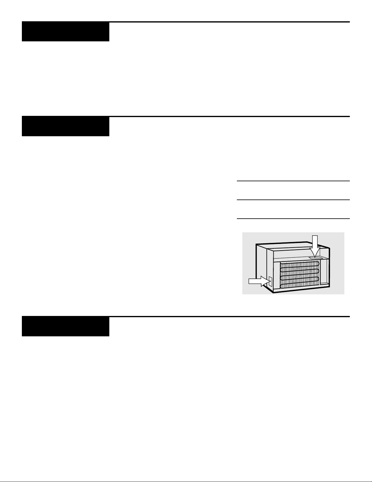
Write down the model and serial
numbers here.
on
the right side of the air discharge
area and on a label near the power
cord.
Model number
Serial number
Date of purchase
They are on a label
Need Help?
Help us
help you
800.626.2000
2
Before you call for service,
there are a few things you can
do to help us serve you better.
Read this manual.
instructions to help you use and
maintain your air conditioner
properly.
Save time and money.
section titled “If Something Goes
Wrong” before calling. This section was designed to solve common
problems you might encounter.
It contains
Check the
If you do need service, you can
relax knowing help is only a phone
call away. A list of toll-free customer
service numbers is included on the
inside back cover. Or call the
Answer Center
24 hours a day, 7 days a week.
®
at 800.626.2000,
GE
Page 3
Important Safety Information
Read all safety information before using
• This air conditioner must be
properly installed in accordance
with the Installation Instructions
before it is used.
• Repair or replace immediately
all electric service cords that have
become frayed or otherwise
damaged.
Extension Cord 115V
If an extension cord is required to
reach the nearest wall receptacle, use
only a UL-listed, 3 wire grounded,
14 gauge, 15A, 125V appliance
extension cord. For models with
nameplate ratings greater than
12 amperes do not use an extension
cord.
• Unplug your air conditioner
before making any repairs.
NOTE:
that any servicing be performed by
a qualified individual.
We strongly recommend
CAUTION:
DO NOT use an extension cord with
any of the 208/230-volt models.
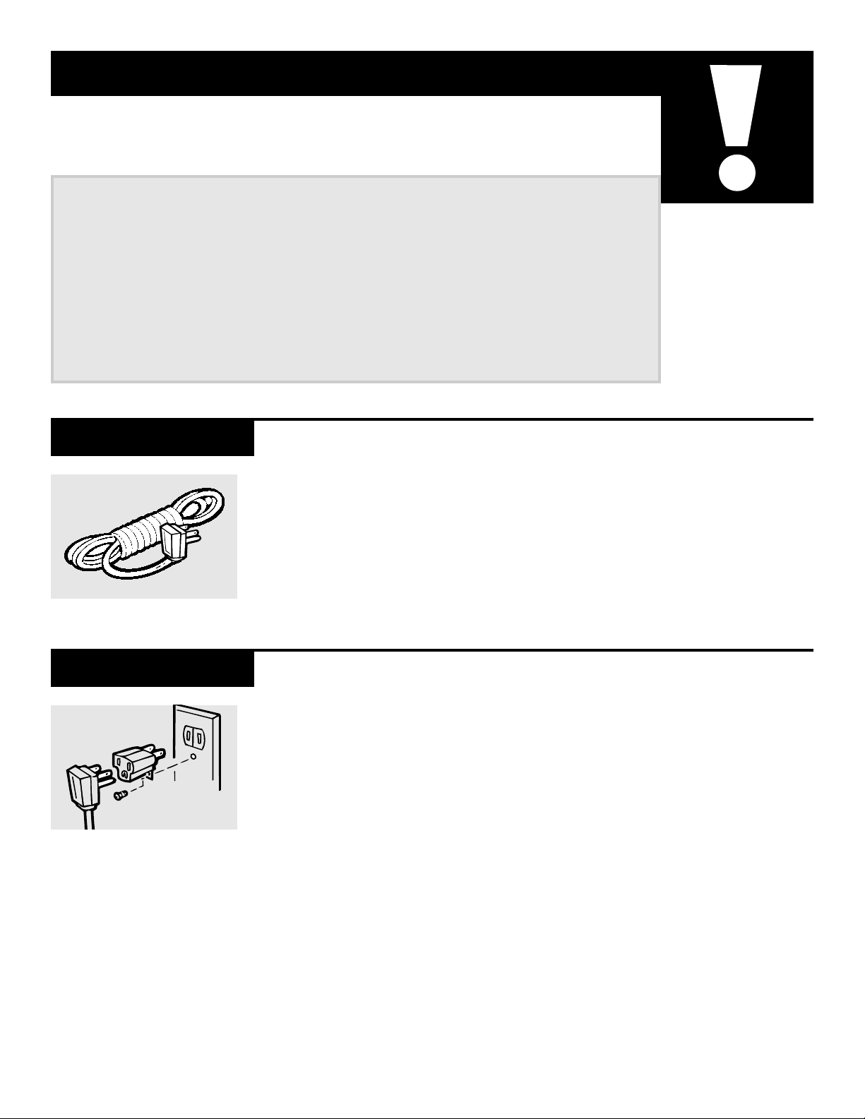
Adapter Plug 115V
Because most 2-prong outlets are
not grounded, we strongly advise
against using an adapter plug.
However, a temporary connection
may be made where local codes
permit and if the 2-prong wall outlet is properly grounded.
This is a temporary method
and is for 115-volt models
only. UL-listed adapters are
available at most hardware
stores.
When you plug the adapter in,
make sure the larger prong goes
into the larger slot to provide the
proper polarity for the power cord.
SAVE THESE INSTRUCTIONS
FOR PROPER GROUNDING:
1 Screw the adapter to the outlet,
using the outlet cover screw.
2 Ground the outlet through the house
wiring.
When disconnecting the power
cord from the adapter, hold the
adapter close to the outlet while
pulling the plug out. If this is not
done, the grounding connector is
likely to break with repeated use.
If the grounding connector breaks,
DO NOT USE
until a proper ground has again
been made.
the air conditioner
3
Page 4
The
controls
Operating Instructions
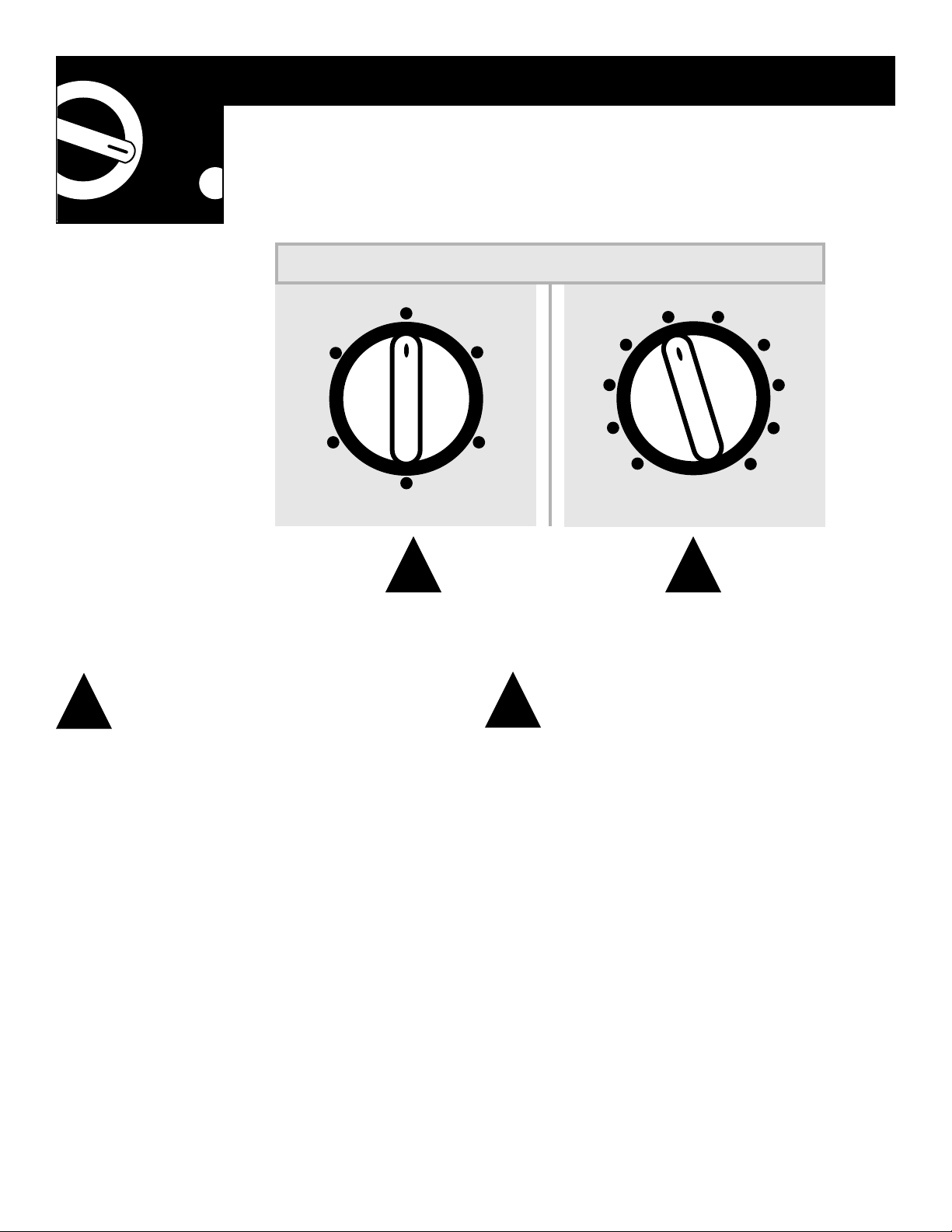
SELECTOR CONTROL THERMOSTAT CONTROL
OFF
LOW
FAN
HIGH
FAN
5
4
3
6
7
8
on your
air
LOW
COOL
HIGH
COOL
MED
COOL
2
1
conditioner
1
1
Selector Control Thermostat Control
HIGH COOL, MED COOL
cooling with different fan speeds.
HIGH FAN
and filtering without cooling.
NOTE:
and
LOW FAN
and
LOW COOL
provide air circulation
provide
2
The thermostat control is used to maintain
the room temperature. The air conditioner will
cycle on and off to keep the room at the same
level of comfort. The higher the number
selected, the cooler the indoor air will become.
2
9
10
•
If you move the switch from a cool setting to
OFF or to a fan setting, wait at least 3 minutes
before switching back to a cool setting.
•
The ENERGY SAVER SWITCH must be in the
normal position in order for high fan and low
fan to operate.
4
Page 5
Cooling Descriptions
FOR NORMAL COOLING
Select
thermostat at 5.
ON
MED COOL
ENERGY SAVER
with the
NORMAL
3 4
FOR MAXIMUM COOLING
Select
thermostat at 10.
HIGH COOL
CLOSED
OPEN
with the
FOR QUIETER & NIGHTIME COOLING
Select
thermostat at 5.
LOW COOL
with the
5
Energy Saver Vent Control Air Direction
The energy saver switch
controls the fan.
ON
—the fan and compressor
cycle on and off together. This
results in wider variations of
room temperature and humidity.
Normally used when the room is
unoccupied.
NORMAL
time, while the compressor
cycles on and off.
This switch must be set at
NORMAL
high or low fan settings (on
the selector control).
—the fan runs all the
in order to use the
43
When the vent control is set at
closed, only the air inside the
room is circulated, cooled and
filtered.
When set at open, some indoor
air will be exhausted from the
room. This will reduce the cooling effect.
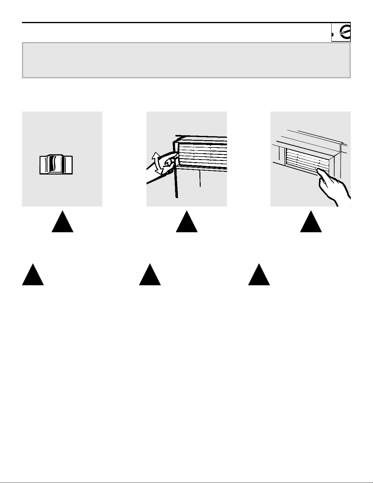
5
Two levers on each side of the
grille let you control the air
direction left or right.
Fingertip pressure on the tabs
adjusts the air direction up or
straight ahead.
DO NOT adjust the louvers down
any lower than straight out.
that is blown down will affect
the thermostat, causing the air
conditioner to turn off before
the room is cooled.
Air
5
Page 6
Operating Instructions
Care & Cleaning
Grille and Case
Outdoor Coils
Air Filter
Turn the air conditioner off and
remove the plug from the wall outlet before cleaning.
The coils on the weather side of
the air conditioner should be
checked regularly. If they are
clogged with dirt or soot they may
be professionally steam cleaned, a
service available through your GE
service outlet.
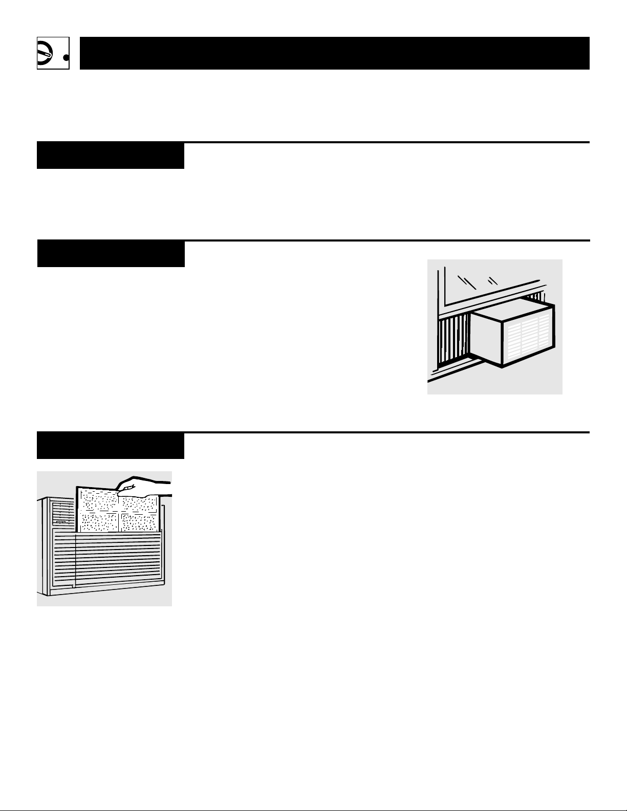
The air filter behind the front
grille should be checked and
cleaned at least every 30 days
or more often if necessary.
To remove:
filter and gently pull it up.
Lift the top of the
To clean, use water and a mild
detergent. Do not use bleach or
abrasives.
The filter can be washed in warm
soapy water. Rinse and let the filter
dry before replacing it.
CAUTION:
DO NOT operate the air conditioner
without a filter because dirt and lint
will clog it and reduce performance.
6
Page 7

Installation Instructions
Important Electrical Safety—Read Carefully
Important Notes
Electrical
Requirements
Parallel
115V., 15 Amp.
Perpendicular
230/208V., 20 Amp.
Tandem
230/208V., 15 Amp.
Large Tandem
230/208V., 30 Amp.
•
Installer: Leave these instructions
with the appliance.
•
Owner: Keep these instructions for
future use.
•
For personal safety, this air
conditioner must be properly
grounded.
•
It is important to have the wall outlet and circuit checked by a qualified electrician if there is any doubt
as to whether a proper ground
exists.
The 230/208-volt models require
their own single branch circuit supplying 230/208-volt a.c., protected
with a time delay fuse or circuit
breaker.
This is recommended for best
performance and to prevent overloading house wiring circuits,
which could cause a possible fire
hazard from overheating wires.
•
Follow national electrical codes or
local codes and ordinances.
CAUTION:
•
Do not, under any circumstances,
cut or remove the third (ground)
prong from the power cord.
•
Do not change the plug on the
power cord of this air conditioner.
•
Aluminum house wiring may
present special problems—
consult a qualified electrician.
The 115-volt models require a
115/120-volt a.c., 60 Hz grounded
outlet protected with a 15-amp
time delay fuse or circuit breaker.
The 3-prong grounding plug
minimizes the possibility of electric
shock hazard.
plan to use is only a 2-prong outlet,
it is your responsibility to have it
replaced with a properly grounded
3-prong wall outlet.
If the wall outlet you
7
Page 8

Installation Instructions
Before you begin
Parts Included
2 sliders
2 filler panels
3/8″ screws (6)
2 sill brackets
2 case side seals
5/8″ machine
screws (2)
and nuts (2)
5/8″ carriage
bolts (2)
and nuts (2)
1″ screws (6)
2 support brackets
5/8″ screws (3)
Foam top window gasket
Case
Upholstery
tacks (4)
Window
locking
bracket
Pkg. of putty
Tools Needed
8
• Blade-type screwdriver
• Ruler or tape measure
• Hammer • Knife
• Level • Scissors
• Hex driver
Page 9

Read completely then follow step-by-step
Window
Requirements
• These instructions are for a
standard double-hung window.
You will need to modify them for
other types of windows.
• The air conditioner can be
installed in a window with an
opening width as narrow as 26
but only if the left- and right-hand
side seals are not installed.
• All supporting parts should be
secured to firm wood, masonry
or metal.
• The electrical outlet must be
within reach of the power cord.
Do not use an extension cord.
5
8
18
⁄
″
263⁄4″ to 40″
3
⁄4″
Window opening dimensions
are for a standard double-hung
window.
min.
Storm Window
Requirements
1/2″ higher
than frame
Storm
window
frame
Wood
Stool
A storm window frame will not
allow the air conditioner to tilt
towards the outside and will keep it
from draining properly. To adjust
for this, attach a piece of wood to
the stool.
WOOD PIECES:
WIDTH:
LENGTH:
2″
Long enough to fit inside
the window frame.
THICKNESS:
To determine the
thickness, place a piece of wood on
the stool to make it 1/2″ higher
than the top of the storm window
frame.
Attach securely with nails or screws.
9
Page 10

Installation Instructions
Window Installation
Remove the Air Filter
and the Front Grille
Remove the Air
Conditioner from
the Case
1
Lift the top of the filter and
gently pull it up.
1
Remove one screw from each
side of the case. Keep these
ground/anti-theft screws so they
may be replaced at the end of
the installation.
2
Remove the two screws and lift
off the grille.
2
Slide the air conditioner from
the case by pulling on the bottom
lip of the air conditioner while
holding the case.
NOTE:
Remove
screws
Mark the
Centerline
10
1
Open the window.
2
Locate and mark the centerline
on the stool.
The air conditioner is very heavy.
It may require 2 or more people to
remove it from the case.
Centerline
Page 11

Install the Case in
the Window
To p
retainer
bar
Slider
Bottom tie bar
1
Place the sliders, one on each
side, into the top retainer bar.
2
Carefully place the case in the
window and align the center of
the bottom tie bar with the centerline on the window stool. Do
not release your grip on the case
until the window is in its final
position.
3
Close the window until it touches
behind the top retainer bar. Do
not close the window so tightly
that the sliders cannot move.
4
Attach the case side seals on the
outside of the case by using three
3/8″ screws on each side.
5
Secure the case through the case
track into the window stool on
each side, using two 1″screws.
Attach
side
seals
Secure
to stool
Assemble and
Attach the Sill and
Support Brackets
Sill
bracket
Carriage bolt
Support bracket
Measure and Cut
the Window Filler
Panels
“X”
Window molding
Nut
1
Loosely attach the sill brackets to
the support brackets with 5⁄8″
long carriage bolts and nuts.
2
Find the track hole that aligns
with the sill bracket on the outer
edge of the window sill. Using
the 5/8″ long machine screws
and nuts attach the support
brackets to the case track hole on
each side.
3
Attach both sill brackets to the
window sill using two 1″ long
screws, one on each side.
4
Tighten the bolts and nuts on
both sides.
1
Measure the distance “X” between
the face of the window molding
and the side of the case. Measure
both sides of the case separately.
2
Subtract 3/16″ (one groove)
from “X” to determine the
required width you need to cut
the filler panels.
Track hole
Sill
Level
When finished, use a level to make
sure the case tilts to the outside
1/4″ minimum. This prevents water
from entering the room.
3
Using a sharp knife, mark the
groove until the filler panel
becomes weak enough to break
apart.
11
Page 12

Installation Instructions
Window Installation
Install the Window
Filler Panels
Case
Leave a small space at the bottom
of the case side seal groove.
Case
Window molding
Slide the filler panel into place.
1
Insert the cut edge of the filler
panel into the case side seal
groove.
2
Push the filler panel backward
toward the window frame until it
clears the window stool.
3
Slide the filler panel out from the
air conditioner case. Make sure it
contacts the window molding.
4
Use upholstery tacks to attach
the filler panel to the face of the
window molding through the
holes provided.
5
Pull the sliders out until they
contact the face of the window
molding. Pull the window down
tightly and lock it in place with
5⁄8″ screws.
Attach through the holes on
each side of the window sash.
6
Attach the window locking
bracket with a 5⁄8″ screw.
Attach
Install the Window
Gasket
Replace the Air
Conditioner
12
1
Cut the foam top window gasket
to the window width.
2
Stuff the foam between the
glass and the window to prevent
air and insects from getting into
the room.
1
Slide the air conditioner into the
case and replace the front grille.
2
Install the two ground/anti-theft
screws removed at the beginning
of the installation.
3
Make sure the unit is
plugging into the outlet.
4
Use the putty to fill in holes or air
leaks.
OFF
before
Page 13

Through-the-Wall Installation
Important Notes
• The case may be installed
through the wall in both existing
buildings and new construction.
• Side louvers in the case must pro-
ject on the outdoor side of the
wall for proper venting of the air
conditioner.
Tools Needed
• Phillips head screwdriver
• The room side of the case must
project into the room at least 1
from the finished wall. See illustration in the Finish the Wall
Opening section.
• The case must be installed level
from side to side and with a 1/4″
minimum tilt from front to rear.
• Tin snips • Drill
1
⁄2″
Materials Needed
(obtain locally)
Prepare the Wall
Opening
Bottom rail
Measure height from the top
of the case to the bottom of
the rail. Measure the width of
the case. Add 1/8″ to each
measurement.
• Blade-type screwdriver
• Magnetic stud finder (optional)
• Concrete saw (if installing
through a masonry wall)
• 12 #10 wood screws, 1″ long
• 1 tube high grade caulking
compound
• Wooden framing studs
1
Determine the size of the
opening by adding 1/8″ to the
height and width of the case.
2
Choose the wall opening location. Be sure a power outlet is
(or will be) installed nearby.
3
Make the opening. Frame it to
support the weight of the air
conditioner.
• Handsaw • Hammer
• Level • Caulking gun
• Chisel • Tape measure
• Lintel, if required, to support
bricks or blocks above opening
• Flashing, aluminum or galva-
nized steel
4
Place metal flashing over the
bottom of the frame opening
and 1″ up on each side to reduce
the possibility of moisture entering the area between the inner
and outer wall. The flashing lip
should be 1″ wide and bent down
45°. See the illustration on the
next page.
13
Page 14

Installation Instructions
Through-the-Wall Installation
Remove the Air
Conditioner from
the Case
Install the Case in
the Wall
Finish the Wall
Opening
1
Remove the air filter and the
front grille.
2
Remove the two grounding/
anti-theft screws from either side
of the case.
1
Place the case in the wall
opening with a 1⁄4″ minimum
tilt to the outside.
2
Secure the bottom rail, case sides
and top to the wooden frame
using 1″ long #10 screws.
1
Caulk the sides and the top on
the outdoor side of the case. On
the roomside, caulk around the
bottom rail to prevent moisture
from getting through to the
interior wall.
3
Slide the air conditioner from
the case by pulling on the bottom
lip of the air conditioner while
holding the case.
For specific instructions, refer to
Window Installation Instructions.
NOTE:
Drill holes in the case sides and top,
if necessary, for proper installation.
If the frame is oversized, use shims
to prevent cabinet distortion.
2
Install wood trim molding, if
desired, on the inside wall
around the case.
14
Brick veneer
Lintel angle
(if required)
Caulking
Flashing
Caulking
Holes for #10
1″ long
wood screws
Plaster
line
Trim
molding
(if desired)
Roomside
Grounding/
anti-theft screw
Caulking
(between
bottom rail
and flashing)
1
⁄2″
1
min.
Page 15

Support Brackets
Support brackets are recommended
for walls under 5″thick. Refer to
the assembly of the support brackets in the Window Installation.
A wooden strip secured to the outside wall should be used with the
sill support brackets.
Replace the Air
Conditioner
1
Slide the air conditioner into the
case and replace the front grille.
2
Install the two ground/anti-theft
screws removed at the beginning
of the installation.
3
Make sure the unit is
plugging into the outlet.
4
Use the putty to fill in holes or air
leaks.
OFF
before
15
Page 16

Helpful Information
Things That Are Normal
Noise Explanation
You may hear a pinging noise caused by water being picked up
and thrown against the condenser on rainy days or when the
humidity is high. This design feature helps remove moisture
and improve efficiency.
PIN
G
!
"CLICK"
D R I P
WHIR!
You may hear the thermostat click when the compressor cycles
on and off.
Water will collect in the base pan during high humidity or on rainy
days. The water may overflow and drip from the outdoor side
of the unit.
The fan may run even when the compressor is not.
16
Page 17

If Something Goes Wrong
Before you call for service
Problem Possible Causes What to Do
Air Conditioner
Doesn’t Start
Air Conditioner Does
Not Cool as it Should
The air conditioner • Make sure the air conditioner plug is
is unplugged pushed completely into the outlet.
The fuse is blown/circuit • Check the house fuse/circuit breaker
breaker is tripped box and replace fuse or reset the
Airflow is restricted
The thermostat control may • Turn the knob to a higher number.
not be set high enough The highest setting provides maximum
The air filter is dirty • Clean the filter at least every 30 days.
The room may have been hot • When the air conditioner is first turned on
Cold air is escaping • Check for open furnace floor registers and
• Make sure there are no curtains, blinds
or furniture blocking the front of the
air conditioner.
cooling.
See the Care and Cleaning section.
you need to allow time for the room to
cool down.
cold air returns.
• Set the vent in the closed position.
breaker.
Air Conditioner
Freezing Up
Cooling coils have iced up • See freezing up below.
Ice blocks the air flow • Set the selector control at high fan or high
and stops the air conditioner cool with the thermostat at 1 or 2.
from cooling the room
17
Page 18

GE Service Numbers
We’ll be there!
GE Answer Center
®
800.626.2000
In-Home Repair Service
800-GE-CARES
(800-432-2737)
Whatever your question about any
GE major appliance, GE Answer
Center
available to help. Your call—and
your question—will be answered
promptly and courteously.
A GE consumer service professional
will provide expert repair service,
scheduled at a time that’s convenient for you. Many GE Consumer
Service company-operated locations offer you service today or
tomorrow, or at your convenience
(7:00 a.m. to 7:00 p.m. weekdays,
9:00 a.m. to 2:00 p.m. Saturdays).
® information service is
And you can call any time. GE
Answer Center
24 hours a day, 7 days a week.
Our factory-trained technicians
know your appliance inside and
out—so most repairs can be handled in just one visit.
® service is open
For Customers With
Special Needs
800.626.2000
18
Upon request, GE will provide
Braille controls for a variety of
GE appliances, and a brochure
to assist in planning a barrier-free
kitchen for persons with limited
mobility. To obtain these items,
free of charge, call 800.626.2000.
Consumers with impaired hearing
or speech who have access to a
TDD or a conventional teletypewriter may call 800-TDD-GEAC
(800-833-4322) to request information or service.
Page 19

Service Contracts
800-626-2224
You can have the secure feeling that GE Consumer Service will still
be there after your warranty expires.
warranty is still in effect and you’ll receive a substantial discount. With a
multiple-year contract, you’re assured of future service at today’s prices.
Purchase a GE contract while your
Parts and Accessories
800-626-2002
Further Service
Individuals qualified to service
their
own appliances can have
parts or accessories sent directly
to their home. The GE parts system
provides access to over 47,000
parts…and all GE Genuine Renewal
Parts are fully warranted. VISA,
MasterCard and Discover cards
are accepted.
We’re proud of our service and
want you to be pleased. If for some
reason you are not happy with the
service you receive, here are three
steps to follow for further help.
First,
contact the people who serviced your appliance. Explain why
you are not pleased. In most cases,
this will solve the problem.
Care and cleaning instructions contained in this manual cover procedures to be performed by any user.
Other servicing generally should be
referred to qualified service personnel. Caution must be exercised,
since improper servicing may cause
unsafe operation.
Finally,
not resolved, write:
Major Appliance Consumer
Action Program
20 North Wacker Drive
Chicago, IL 60606
if your problem is still
Next,
if you are still not pleased,
write all the details—including
your phone number—to:
Manager, Consumer Relations
GE Appliances, Appliance Park
Louisville, KY 40225
19
Page 20

AIR
CONDITIONER
WARRANTY
Staple sales slip or cancelled check here. Proof of original purchase
date is needed to obtain service under warranty.
What is Covered
What is Not
Covered
FULL ONE-YEAR WARRANTY
For one year from date of original purchase, we will provide, free of charge,
parts and service labor in your home to
repair or replace any
conditioner that fails because of
facturing defect.
FULL FIVE-YEAR WARRANTY
For five years from the date of original
purchase, we will provide, free of charge,
parts and service labor in your home to
repair or replace any part of the sealed refrig-
erating system (the compressor, condenser,
evaporator and all connecting tubing)
that fails because of a manufacturing
defect.
• Service trips to your home to teach
you how to use the product.
Read your Owner’s Manual. If you then
have any questions about
product, please contact
our Consumer Affairs office at the
address below, or call, toll free:
GE Answer Center
800.626.2000
consumer information service
• Improper installation.
If you have an installation problem, or
if the air conditioner is of improper
cooling capacity for the intended use,
contact your dealer or installer. You
responsible for providing adequate
trical connecting facilities.
part of the room air
a manu-
operating the
your dealer or
®
are
elec-
**********************************
This warranty is extended to the origi-
nal purchaser and any succeeding
owner for products purchased for use
in the 48 mainland states, Hawaii and
Washington, D.C. In Alaska the warranty
is the same except that it is LIMITED
because you must pay to ship the product to the service shop or for the service
technician’s travel costs to your home.
All warranty service will be provided by
our Factory Service Centers or by our
authorized Customer Care
during normal working hours.
Should your appliance need service,
during warranty period or beyond,
call 800-GE-CARES (800-432-2737).
• Replacement of house fuses or reset-
of circuit breakers.
ting
• In commercial locations labor neces-
sary to move the unit to a location
where it is accessible for service by an
individual technician.
• Failure of the product resulting from
modifications to the product or due
to unreasonable use including failure
to provide reasonable and necessary
maintenance.
Failure due to corrosion on models not
•
corrosion-protected.
•
Damage to product caused by improper power supply voltage, accident,
floods or acts of God.
servicers
®
fire,
WARRANTOR IS NOT RESPONSIBLE FOR CONSEQUENTIAL DAMAGES.
Some states do not allow the exclusion or limitation of incidental or consequential damages, so the above limitation
or exclusion may not apply to you. This warranty gives you specific legal rights, and you may also have other rights
which vary from state to state. To know what your legal rights are in your state, consult your local or state consumer
affairs office or your state’s Attorney General.
Warrantor: General Electric Company If further help is needed concerning this warranty, write:
Manager—Consumer Affairs, GE Appliances, Louisville, KY 40225
Part No. 23-11-2009N-001
Pub. No. 49-7334
9-95 CG
Printed in the United States
AVM14 AVM22
AVM15 AVM24
AVM18
 Loading...