

Page 1
Revision 1.0 (06/2007) • Part number AS610RF_v1-0_multilingual
www.gesecurity.eu
•
Copyright © 2007 GE Security B.V. All rights reserved
AS610RF Radio self-powered siren,
bi-directional with lithium batteries
Installation Instructions
NL
Installation Instructions
Introduction
The AS610RF system from GE Security is a wireless siren with a
transceiver unit and lithium batteries. In this document the
various components are referred to as:
AS610RF Wireless siren
AS610RF-TR Transceiver unit
BS60 Lithium battery pack
General description
The AS610RF self-powered siren is an external wireless bi-directional
siren. It requires the standalone transceiver unit AS610RF-TR, setup in
any configuration. The siren runs on a lithium battery pack of 2 size “D”
3.6 V lithium batteries.
The AS610RF siren
The siren is protected against the removal of its cover and against
being removed from the wall. It has an internal metal cover. It can
receive signals from the AS610RF-TR card control for alarm activation
and system status. It can also transmit to the control panel the
supervision signal, battery voltage control, and tamper information.
The AS610RF-TR transceiver unit
The transceiver unit consists of 2 control inputs for alarm, 2 inputs for
signalling the on/off status of the control panel, and the P1 button
which when pressed continuously transmits the code to be memorized
on the sirens.
The receiving section of the transceiver unit consists of a display, 4
LED indicators, 2 open collector outputs, 1 relay output (NC) and the
P2 button.
The display shows the siren (1 to 8) that has indicated a problem. If
there is more than one siren with an event, the display starts to cycle,
displaying the number of the siren for 2 seconds, while the 3 LEDs
show the type of event that was received.
The 3 surface-mounted LEDs (DL1, DL2 and DL3) show which type of
event is present at the sirens: tamper (DL1), no supervision (DL2) and
low battery (DL3). The tamper LED is reset upon activation of the
On/Off inputs on T3 or T4. The other two LEDs are reset when the
battery power or radio transmission is restored.
The red LED (DL4) collects all the signals from the LEDs DL1, DL2 and
DL3.
Button P2 is used to access programming, memorize siren codes, and
exit programming.
DIP switches in the wireless siren
Use the DIP switches to set the independent alarm time, change the
type of siren modulation, bypass or enable the sound signal linked to
the On/Off input, set the sound level on 2 levels, and bypass or enable
the optic signal linked to the On/Off input.
DIP1 DIP2 Siren time Flashing time
OFF OFF
30 s 30 s
ON OFF
60 s 30 s
OFF ON
90 s 90 s
ON ON
90 s 300 s
DIP3 DIP4 Siren modulation
OFF OFF
High frequency sweep: min.
2600 Hz to max. 3600 Hz
ON OFF
Low frequency sweep: min.
1400 Hz to max. 2000 Hz
OFF ON
High frequency double tone:
min. 2600 Hz to max. 3600 Hz
ON ON
Low frequency double tone:
min. 1400 Hz to max. 2000 Hz
DIP5 Sound signal (BEEP) at each arm/disarm of the system
ARM system: 3 beeps
DISARM system: 1 long beep
OFF
Bypassed
ON
Enabled
DIP6 Optical signal (FLASHING) at each arm/disarm of the
system
ARM system: 3 flashes
DISARM system: 1 long flash
OFF
Bypassed
ON
Enabled
DIP7 Beep intensity
OFF
Low
ON
High
DIP8
Not used
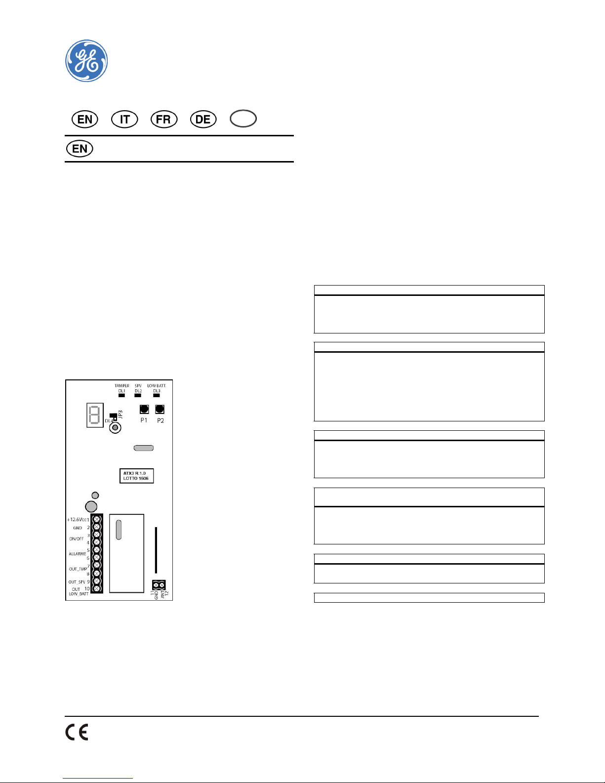
Terminal board in the transceiver unit
Terminal no. 1 Positive power supply 12.6 VDC
Terminal no. 2 Negative power supply GND
Terminal no.3 ON/OFF input for negative signals (0 V equals
control panel ARM)
Terminal no.4 ON/OFF input for positive signals (12 V equals
control panel ARM)
Terminal no.5 ALARM input for negative signals
Page 2

2
Terminal no.6 ALARM input for positive signals
Terminal no.7 TAMPER (relay NC 100 mA)
Terminal no.8 TAMPER (relay NC 100 mA)
Terminal no.9 SUPERVISION output max 30 mA
Terminal no.10 LOW BATTERY output max 30 mA
Terminal no.11 GND
Terminal no.12 Antenna output
Inputs and outputs on the transceiver unit
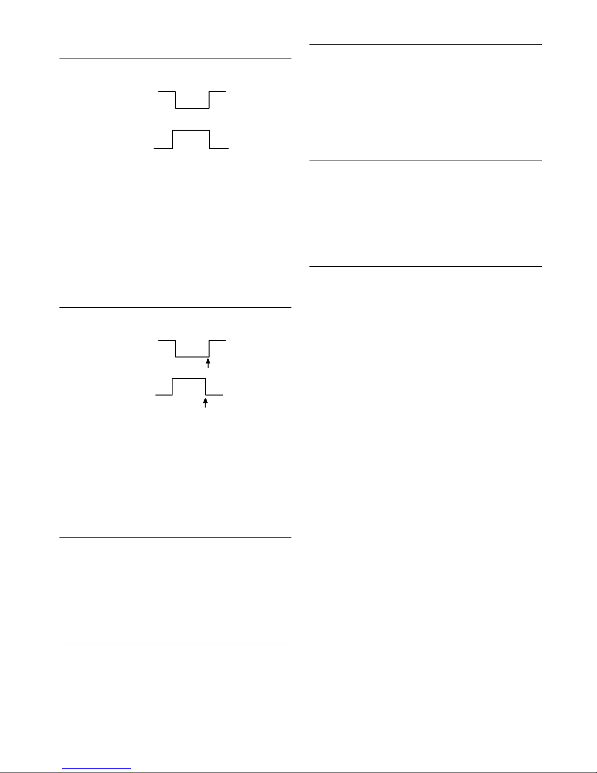
ON/OFF inputs Terminal no. 3 or no. 4
T3 ON/OFF input from control panel output.
+12
V
0 V
Arm Disarm
OR T4
+12 V
0 V
Arm Disarm
Terminal no. 3
Input to be connected to the ON/OFF output of
the control panel. When going to LOW level
(GND) for more than a second, there is a system
ON transmission for 2 seconds. This is indicated
with the letter "A" on steady. When it returns to
HIGH level for more than a second, there is a 2
second system OFF transmission.
Terminal no. 4
Input to be connected to the ON/OFF output of
the control panel. When going to HIGH level (12
VDC) for more than a second, there is a system
ON transmission for 2 seconds. This is indicated
with the letter "A" on steady. When it returns to
LOW level for more than a second, there is a
2 second system OFF transmission.
ALARM inputs Terminal no. 5 or no.6
T5 Alarm input from control panel output.
+12
V
0 V
Alarm Reset
OR T6
+12
V
0 V
Alarm Reset
Terminal no. 5
Input to be connected to the alarm output of the
control panel. When going to LOW level (GND)
for more than a second, there is an alarm
transmission to the siren for 2 seconds. When it
returns to HIGH level, there is a 2 second
transmission that silences the radio sirens.
Terminal no. 6
Input to be connected to the alarm output of the
control panel. When going to HIGH level (12
VDC) for more than a second, there is an alarm
transmission to the sirens for 2 seconds. When it
returns to LOW level, there is a 2 second
transmission that silences the radio sirens.
Tamper output Terminals no.7 and no.8
This relay output (with normally closed contact)
collects all tamper indications from the
memorized sirens.
When a tamper transmission is received from
one of the sirens, the output opens for
2 seconds. The display and the tamper LED DL1
memorize and display the event. This condition
persists until the next time the control panel is
activated.
Terminal no. 9 Supervision
This open collector output collects lack of
supervision signals from all memorized sirens.
If no supervision signal is received from the
memorized sirens in 3 hours, this output is
switched to low level. The display and the
supervision LED DL2 display and memorize the
event. This condition persists until the resolution
of the problem that generated it.
LOW BATT output Terminal no. 10
This open collector output collects all low
battery events from the memorized sirens.
When a low battery transmission arrives from
one of the memorized sirens, the output is
switched to low level. The display and the low
battery LED DL3 display and memorize the
event. This condition persists until the flat
batteries of the siren are replaced.
Buttons in the transceiver unit
Button P1 Use this button to constantly transmit a radio
signal so as to memorize it in the external sirens.
In this phase, the display shows a flashing letter
“t”.
During programming it is used to cancel a siren
code.
During power-on (first start-up) it generates a
new 16-bit code. In this phase it displays lateral
dashes in continuous rotation.
Button P2 Use this button to access programming in order
to select the 8 zones to be memorized. It is also
used to exit programming.
Jumper J3 in the transceiver unit
Jumper J3 is used to bypass LED DL4 in the event of lack of
supervision. Independent of the status of J3, LED DL2 will monitor the
non-supervision events.
J3 ON (closed) = LED DL4 enabled
J3 OFF (open) = LED DL4 bypassed
Setting up the system
A. The AS610-RF wireless siren:
Open the top cover. Unscrew and remove the metal cover. Set the
DIP switches in the desired configuration. See section “DIP switches in
the wireless siren”.
Connect the batteries by plugging the connector into J4.
Carry out code learning procedures prior to installation – see section
“Memorization of the codes”. Check operation and then install the siren
on the wall.
If the microprocessor has been incorrectly initialized, for example the
batteries are incorrectly inserted, it will not be possible to memorize
the codes. In this case remove the batteries and firmly re-insert them,
making sure there is good contact.
Page 3

3
B. The AS610RF-TR transceiver unit:
For convenience, memorization may be done before the unit is
installed. This facilitates the verification of code learning. Programming
must be performed with the ON/OFF and ALARM inputs in standby
status:
Connect T3 to +ve or T4 to –ve
Connect T5 to +ve or T6 to –ve
Connect power to T1 and T2
Memorization of the codes
The siren and transceiver module are delivered from the factory not
linked to each other. Before installation you need to memorize the
unique code from the transceiver on the siren and vice-versa.
If you have more than one siren in a system, you should use 1
transceiver in your system and individually program each siren on the
transceiver unit. The transceiver unit can control up to 8 wireless
sirens with the possibility to receive and manage all information
coming from the memorized sirens.
A. To memorize the AS610RF-TR transceiver on the AS610RF siren:
1. Press button P1 on the siren. LED DL1 will come on steady.
2. Release button P1 within 5 seconds. The LED DL1 will start
flashing slowly.
3. On the transceiver card, press button P1. The siren memorizes
the code and confirms with a beep and by flashing the LED.
B. To memorize the AS610RF siren on the AS610RF-TR transceiver:
1. On the transceiver card, press button P2 for at least 5 seconds.
The display shows “P” for 2 seconds and then a flashing “ 1 ” .
2. On the siren card, press button P1. Continue pressing P1 for
approximately 10 seconds (LED is off – LED comes ON – LED
starts flashing). As soon as the LED starts to flash, release button
P1. When a valid code is received, the display on the transceiver
comes on steady to confirm memorization, and confirms with a
beep.
To program more than 1 siren, each brief press of button P2 causes
the display to show in sequence number 2, 3, 4, 5, 6, 7, 8 and then back
to 1, 2 etc.
C. To exit programming:
Press P2 for at least 5 seconds. The display shows the central dash
and normal receive operations begin.
There is also an automatic exit from programming after 3 minutes.
D. To cancel a memorized code:
1. Press P2 for at least 5 seconds, and use P2 to select the number
of a previously memorized siren (display on steady).
2. Press P1 for at least 5 seconds. The display will start flashing as it
stands by for a new valid code.
3. Press P2 to exit programming.
Installation
Installing the siren
Use the 4 openings of the back plate to attach the siren to the desired
location. Do not install the siren on metallic surfaces, which may have
a negative impact on radio range. Avoid placing it too close to possible
magnetic fields, such as electrical panels, electrical power meters,
cranes, scaffolding, etc. The side of the siren where the internal
antennas are located must not be placed near iron girders, niches in
sheet metal, etc. Place the siren as near as possible to the AS610RF-TR
card.
Installing the transceiver unit
Mount the unit inside the control panel if it is a plastic housing, or
outside of the control panel in a plastic housing with a tamper switch.
Connect the inputs and outputs according to section “Description of
inputs and outputs on the transceiver unit”, and power the unit.
Testing the system
Run several tests to check that the siren is operating correctly: from
the control panel where the AS610RF-TR card has been previously
installed, transmit an alarm signal and the activation/de-activation
signal. Check the communication from the siren to the transceiver by
performing a tamper test, for example.
Close the siren’s metal and plastic cover with the screws provided. Run
the radio check again.
Notes on siren anti-tampering
When tampering is detected, the siren immediately sends a tamper
signal to the control unit and an alarm cycle is independently started.
To allow the enclosure to be opened without generating an alarm, the
anti-tampering circuit is not processed for the first 30 seconds after
each receipt of the system disarm signal.
Notes on low battery level control
When battery level drops below 6 V, this information is inserted in all
transmissions to the control unit. The sound signal doubles its
operating frequency and the luminous panel flashes more rapidly.
If the sound and optic signals have been bypassed using DIP switches
5 and 6, they will activate automatically when the batteries are low.
Technical specifications
AS610RF wireless siren
Nominal operating voltage .....7.2 VDC (2x3.6 size "D" Lithium batteries)
Battery pack ............................................................................................................. BS60
Power input in standby:..........................................................................100 microA
Maximum power input ..................................................................................500 mA
Operating frequency................................................................................433.92 Mhz
Transmitting module power.......................................................................... 10 mW
Radio range................................................................................. 100 m in open field
Sound output at 1 m......................................................................................... 105 dB
Sound frequency................................... 2600 to 3600 Hz or 1400 to 2000 Hz
Cut-off timer...........................................................................................30 s, 60 s, 90 s
Operating temperature ......................................................................-25 to + 40°C
Housing ...................................................................................................Polycarbonate
Dimensions.................................................................................. 300 x 210 x 87 mm
AS610RF-TF transceiver unit
Nominal operating voltage.......................................................................... 12 V DC
Current consumption – nominal ..................................................................20 mA
Current consumption – maximal ...................................................... 70 mA max
Transmission frequency.........................................................................433.92 Mhz
Reception frequency................................................................................433.92 Mhz
Operating temperature ...................................................................... + 5 to + 40°C
2-year limited warranty
GE Security B.V. warrants that this product will be free of defects in
material and workmanship for two years from the date of production.
This warranty is limited to repair or replacement at GE Security’s
option. Damages caused by modification, abuse or misuse, wear and
tear, improper installation, application, storage, fault or negligence of a
party other than GE Security B.V. is not covered. GE Security B.V. will
not be responsible for labor costs of removal or reinstallation of
products. The repaired or replaced product is then warranted under
the terms of this Limited Warranty for the balance of the term of the
Warranty or for 90 days whichever is longer. GE SECURITY MAKES NO
OTHER WARRANTY EXPRESS OR IMPLIED OF MERCHANTABILITY OR
FITNESS FOR A PARTICULAR PURPOSE. IN NO EVENT SHALL GE
SECURITY BE LIABLE FOR LOSS OF USE, LOST PROFITS, THEFT,
PROPERTY DAMAGE, SPECIAL, INCIDENTAL OR CONSEQUENTIAL
DAMAGES. To obtain repair or replacement information under the
terms of this warranty, please contact your local supplier.
www.gesecurity.eu.
The European directive “Waste Electrical and Electronic Equipment”
(WEEE) aims to minimise the impact of electrical and electronic
equipment waste on the environment and human health. For proper
treatment, recovery and recycling, you can return the equipment
marked with this symbol to your local supplier upon the purchase of
equivalent new equipment, or dispose of it in designated collection
points. Further information can be found on the following website:
www.recyclethis.info
European representative for manufacture (EMC): GE Security B.V.,
Kelvinstraat 7, 6003 DH Weert, The Netherlands.
Page 4
4
Istruzioni per l'installazione
Introduzione
Il sistema AS610RF di GE Security è una sirena wireless dotata di unità
ricetrasmittente e batterie al litio. In questo documento verrà fatto
riferimento ai seguenti componenti:
• AS610RF Sirena wireless
• AS610RF-TR Unità ricetrasmittente
• BS60 Batteria al litio
Descrizione generale
AS610RF è una sirena esterna wireless bidirezionale autoalimentata.
Richiede l'unità ricetrasmittente indipendente AS610RF-TR, in qualsiasi
configurazione. La sirena funziona con due batterie al litio tipo “D” da
3,6 V.
La sirena AS610RF
La sirena è dotata di protezioni che impediscono di rimuovere
l'apparecchio dalla parete o di sollevarne il coperchio. Ha inoltre un
coperchio interno in metallo. È in grado di ricevere segnali dalla
scheda AS610RF-TR per l'attivazione di allarmi e informazioni sullo
stato del sistema. Può infine trasmettere alla centrale il segnale di
supervisione, il controllo della tensione della batteria, nonché eventuali
informazioni di manomissione.
L'unità ricetrasmittente AS610RF-TR
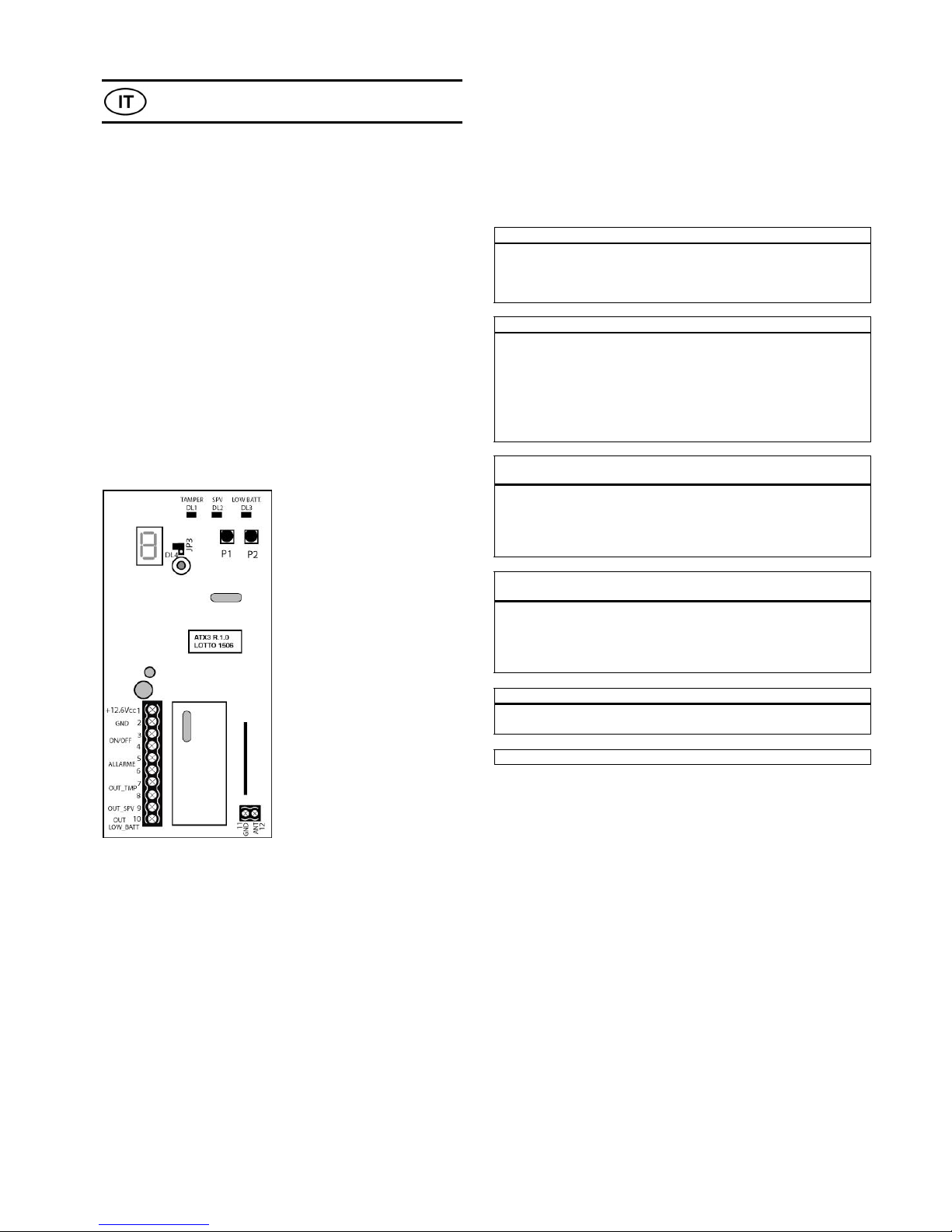
L'unità ricetrasmittente comprende 2 ingressi di controllo per allarme,
2 ingressi per la segnalazione dello stato di
inserimento/disinserimento della centrale e il pulsante P1 che, quando
premuto in modo continuo, trasmette il codice da memorizzare sulle
sirene.
La sezione ricevente dell'unità ricetrasmittente comprende un display,
4 indicatori LED, 2 uscite open collector, 1 uscita relè (NC) e il pulsante
P2.
Sul display viene indicata la sirena (da 1 a 8) dalla quale proviene la
segnalazione di un problema. Se più di una sirena segnala un evento, il
display mostra a rotazione il numero delle sirene interessate ogni 2
secondi, mentre i 3 LED indicano il tipo di evento ricevuto.
I 3 LED (DL1, DL2 e DL3) mostrano il tipo di evento segnalato dalle
sirene: manomissione (DL1), assenza di supervisione(DL2) e batteria
scarica (DL3). Il LED di manomissione viene resettato all'attivazione
degli ingressi On/Off su T3 o T4; gli altri due LED vengono resettati
quando vengono ripristinate le condizioni di normalità, ossia
rispettivamente la trasmissione radio o l'alimentazione della batteria.
Il LED rosso (DL4) raccoglie tutti i segnali provenienti dai LED DL1, DL2
e DL3.
Il pulsante P2 consente di accedere alla programmazione,
memorizzare i codici delle sirene e uscire dalla modalità di
programmazione.
Interruttori DIP switch nella sirena wireless
Gli interruttori DIP switch consentono di impostare il tempo di allarme
indipendente, di cambiare il tipo di modulazione della sirena, di
escludere o abilitare il segnale acustico collegato all'ingresso On/Off, di
impostare uno dei due livelli audio disponibili e di escludere o abilitare
il segnale ottico collegato all'ingresso On/Off .
DIP1 DIP2 Tempo sirena Tempo lampeggiamento
OFF OFF
30 s 30 s
ON OFF
60 s 30 s
OFF ON
90 s 90 s
ON ON
90 s 300 s
DIP3 DIP4 Modulazione sirena
OFF OFF
Scansione alta frequenza: da 2600 Hz (min) a
3600 Hz (max)
ON OFF
Scansione bassa frequenza: da 1400 Hz (min) a
2000 Hz (max)
OFF ON
Doppio tono alta frequenza: da 2600 Hz (min) a
3600 Hz (max)
ON ON
Doppio tono bassa frequenza: da 1400 Hz (min) a
2000 Hz (max)
DIP5 Segnale acustico (bip) ad ogni inserimento/disinserimento
del sistema
Inserimento sistema: 3 segnali acustici
Disinserimento
sistema:
1 segnale acustico lungo
OFF
Escluso
ON
Abilitato
DIP6 Segnale ottico (lampeggiamento) ad ogni
inserimento/disinserimento del sistema
Inserimento sistema: 3 lampeggiamenti
Disinserimento
sistema:
1 lampeggiamento lungo
OFF
Escluso
ON
Abilitato
DIP7 Intensità del segnale acustico
OFF
Bassa
ON
Alta
DIP8
Non utilizzato
Morsettiera dell'unità ricetrasmittente
Terminale n. 1 Alimentazione polo positivo 12,6 V
Terminale n. 2 Alimentazione polo negativo GND
Terminale n. 3 Ingresso ON/OFF per segnali negativi (0 V =
inserimento centrale)
Terminale n. 4 Ingresso ON/OFF per segnali positivi (12 V =
inserimento centrale)
Terminale n. 5 Ingresso ALLARME per segnali negativi
Terminale n. 6 Ingresso ALLARME per segnali positivi
Terminale n. 7 MANOMISSIONE (relè NC 100 mA)
Terminale n. 8 MANOMISSIONE (relè NC 100 mA)
Terminale n. 9 Uscita SUPERVISIONE max 30 mA
Terminale n. 10 Uscita BATTERIA SCARICA max 30 mA
Terminale n. 11 GND
Terminale n. 12 Uscita ANTENNA
Page 5
5
Ingressi e uscite dell'unità ricetrasmittente
Ingressi ON/OFF Terminale n. 3 o n. 4
T3 Ingresso ON/OFF dall'uscita della centrale.
+12
V
0 V
Arm Disarm
OPPURE T4
+12
V
0 V
Arm Disarm
Terminale n. 3
Ingresso da collegare all'uscita
inserito/disinserito della centrale. Quando il
livello è basso (GND) per più di un secondo, viene
attivata una trasmissione sistema inserito per 2
secondi, indicata dalla lettera "A" sul display.
Quando viene ripristinato il livello alto per più di
un secondo, viene attivata una trasmissione
sistema disinserito per 2 secondi.
Terminale n. 4
Ingresso da collegare all'uscita
inserito/disinserito della centrale. Quando il
livello è alto (12 V ) per più di un secondo,
viene attivata una trasmissione sistema inserito
per 2 secondi, indicata dalla lettera "A" sul
display. Quando viene ripristinato il livello basso
per più di un secondo, viene attivata una
trasmissione sistema disinserito per 2 secondi.
Ingressi allarme Terminale n. 5 o n. 6
T5 Ingresso allarme dall'uscita della centrale.
+12
V
0 V
Alarm Reset
OPPURE T6
+12
V
0 V
Alarm Reset
Terminale n. 5
Ingresso da collegare all'uscita allarme della
centrale. Quando il livello è basso (GND) per più
di un secondo, viene attivata una trasmissione
allarme alle sirene per 2 secondi. Quando viene
ripristinato il livello alto, viene attivata per 2
secondi una trasmissione che disattiva le sirene
radio.
Terminale n. 6
Ingresso da collegare all'uscita allarme della
centrale. Quando il livello è alto (12 V ) per più
di un secondo, viene attivata una trasmissione
allarme alle sirene per 2 secondi. Quando viene
ripristinato il livello basso, viene attivata per 2
secondi una trasmissione che disattiva le sirene
radio.
Uscita
manomissione
Terminali n. 7 e n. 8
Questa uscita relè (con contatto normalmente
chiuso) raccoglie tutte le indicazioni di
manomissione provenienti dalle sirene
memorizzate.
Quando viene ricevuta una trasmissione di
manomissione da una delle sirene, l'uscita si apre
per 2 secondi. L'evento viene memorizzato e
segnalato sul display e dal LED di manomissione
DL1. Questa condizione persiste fino alla
successiva attivazione della centrale.
Uscita
supervisione
Terminale n. 9
Questa uscita open collector raccoglie l'assenza
di segnali di supervisione da tutte le sirene
memorizzate.
Se in un intervallo di 3 ore non viene ricevuto
alcun segnale di supervisione emesso dalle
sirene memorizzate, questa uscita viene
commutata su livello basso. L'evento viene
memorizzato e segnalato sul display e dal LED di
supervisione DL2. Questa condizione persiste
fino alla risoluzione del problema che l'ha
generata.
Uscita batteria
scarica
Terminale n. 10
Questa uscita open collector raccoglie tutti gli
eventi batteria scarica segnalati dalle sirene
memorizzate.
Quando da una delle sirene memorizzate viene
ricevuta una trasmissione di batteria scarica,
l'uscita viene commutata su livello basso.
L'evento viene memorizzato e segnalato sul
display e dal LED di batteria scarica DL3. Questa
condizione persiste fino alla sostituzione delle
batterie della sirena.
Pulsanti dell'unità ricetrasmittente
Pulsante P1 Utilizzare questo pulsante per trasmettere
costantemente un segnale radio e consentirne la
memorizzazione nelle sirene esterne. In questa
fase sul display viene visualizzata la lettera “t”
lampeggiante.
Durante la programmazione il pulsante permette
di annullare il codice di una sirena.
Durante il primo avvio, il pulsante consente di
generare un nuovo codice a 16 bit. In questa fase
sul display vengono visualizzate lineette in
rotazione continua.
Pulsante P2 Utilizzare questo pulsante per accedere alla
programmazione per la selezione delle 8 zone da
memorizzare. Il pulsante consente inoltre di
uscite dalla modalità di programmazione.
Ponticello J3 dell'unità ricetrasmittente
Il ponticello J3 viene utilizzato per escludere il LED DL4 in caso di
assenza di supervisione. Indipendentemente dallo stato di J3, il LED
DL2 monitora gli eventi di non supervisione.
J3 ON (chiuso) = LED DL4 abilitato
J3 OFF (aperto) = LED DL4 escluso
Impostazione del sistema
A. Sirena wireless AS610-RF:
Aprire il coperchio superiore. Svitare e rimuovere il coperchio in
metallo. Impostare gli interruttori DIP switch nella configurazione
desiderata. Vedere la sezione “Interruttori DIP switch nella sirena
wireless”.
Collegare le batterie inserendo il connettore nel ponticello J4.
Eseguire le procedure di apprendimento del codice prima di effettuare
l'installazione (vedere la sezione “Memorizzazione dei codicii”.
Verificare il funzionamento, quindi procedere all'installazione della
sirena a parete.
Se l'inizializzazione del microprocessore non è stata correttamente
completata (ad esempio, per l'inserimento non corretto delle batterie),
non sarà possibile memorizzare i codici. In questo caso rimuovere le
batterie e reinserirle correttamente, verificando che facciano bene
contatto.
B. Unità ricetrasmittente AS610RF-TR:
Per comodità, la memorizzazione può essere eseguita prima di
procedere all'installazione dell'unità. Questo semplifica la verifica
dell'apprendimento dei codici. La programmazione deve essere
eseguita con gli ingressi ON/OFF e allarme nello stato di standby:
Page 6

6
• Collegare T3 a +ve o T4 a –ve.
• Collegare T5 a +ve o T6 a –ve.
• Collegare l'alimentazione a T1 e T2.
Memorizzazione dei codici
La sirena e il modulo ricetrasmettitore di fabbrica non sono collegati
l'una all'altro. Prima dell'installazione è necessario memorizzare il
codice univoco trasmesso dal ricetrasmettitore sulla sirena e
viceversa.
Se il sistema comprende più di una sirena, utilizzare 1 ricetrasmettitore
nel sistema e programmare singolarmente ciascuna sirena sull'unità
ricetrasmittente. L'unità ricetrasmittente può controllare fino a 8 sirene
wireless con la possibilità di ricevere e gestire tutte le informazioni
provenienti dalle sirene memorizzate.
A. Per memorizzare il ricetrasmettitore AS610RF-TR sulla sirena
AS610RF:
1. Premere il pulsante P1 sulla sirena. Il LED DL1 si accende di luce
fissa.
2. Rilasciare il pulsante P1 entro 5 secondi. Il LED DL1 inizia a
lampeggiare lentamente.
3. Sulla scheda del ricetrasmettitore, premere il pulsante P1. La
sirena memorizza il codice e conferma l'esecuzione
dell'operazione con l'attivazione di un segnale acustico e del LED
lampeggiante.
B. Per memorizzare la sirena AS610RF sul ricetrasmettitore
AS610RF-TR:
1. Sulla scheda del ricetrasmettitore, premere il pulsante P2 per
almeno 5 secondi. Sul display viene visualizzata la lettera “P” per
2 secondi, quindi inizia a lampeggiare il numero “1”.
2. Sulla scheda della sirena, premere il pulsante P1. Tenere premuto
P1 per circa 10 secondi (il LED è spento, poi si accende, infine
inizia a lampeggiare). Non appena il LED inizia a lampeggiare,
rilasciare il pulsante P1. Quando viene ricevuto un codice valido,
la memorizzazione viene confermata con l'accensione del display
del ricetrasmettitore e l'emissione di un segnale acustico.
3. Se si desidera programmare più di 1 sirena, ad ogni breve
pressione del pulsante P2 vengono visualizzati in sequenza i
numeri 2, 3, 4, 5, 6, 7, 8, quindi di nuovo 1, 2 e così via.
C. Per uscire dalla modalità programmazione:
Premere il pulsante P2 per almeno 5 secondi. Sul display viene
visualizzato il trattino centrale (-) e iniziano le normale operazioni di
ricezione.
Oppure, dopo 3 minuti la modalità di programmazione viene chiusa
automaticamente.
D. Per annullare un codice memorizzato:
1. Premere P2 per almeno 5 secondi; lo stesso pulsante consente
inoltre di selezionare il numero di una sirena precedentemente
memorizzata (display acceso).
2. Premere il pulsante P1 per almeno 5 secondi. Il display inizia a
lampeggiare a indicare l'attesa per la ricezione di un nuovo
codice valido.
3. Premere il pulsante P2 per uscire dalla modalità
programmazione.
Installazione
Installazione della sirena
Utilizzare i 4 fori sulla piastra posteriore per fissare la sirena nel punto
desiderato. Non installare la sirena su superfici metalliche, che
possono interferire negativamente sulla portata radio. Evitare di
posizionarla troppo vicino a campi magnetici, come quelli generati, ad
esempio, da quadri elettrici, misuratori di corrente elettrica, gru,
impalcature, e così via. Il lato della sirena sul quale sono collocate le
antenne interne non deve essere posizionato in prossimità di travature
in ferro, in nicchie presenti in lamiere di metallo, e così via. La sirena
deve essere installata il più vicino possibile alla scheda AS610RF-TR.
Installazione dell'unità ricetrasmittente
Montare l'unità all'interno della centrale se dotata di un involucro in
plastica, oppure esternamente alla centrale in un contenitore in
plastica con interruttore antimanomissione.
Collegare gli ingressi e le uscite come descritto nella sezione “Ingressi
e uscite dell'unità ricetrasmittente” e accendere l'unità.
Test del sistema
Eseguire diversi test per verificare che la sirena funzioni
correttamente: dalla centrale in cui è stata precedentemente installata
la scheda AS610RF-TR, trasmettere un segnale di allarme e il segnale
di inserito/disinserito. Controllare la comunicazione dalla sirena al
ricetrasmettitore eseguendo, ad esempio, un test di manomissione.
Chiudere il coperchio in metallo e plastica della sirena utilizzando le viti
fornite in dotazione. Eseguire nuovamente il controllo radio.
Note sul sistema antimanomissione della sirena
Quando viene rilevata una manomissione, la sirena invia
immediatamente un segnale di manomissione all'unità di controllo e
viene avviato in modo indipendente un ciclo di allarme.
Per consentire l'apertura dell'involucro senza l'attivazione di un
allarme, il circuito antimanomissione non viene monitorato per i primi
30 secondi dopo ciascuna ricezione di un segnale di disinserimento del
sistema.
Note sul controllo del livello di batteria scarica
Quando il livello della batteria scende al di sotto dei 6 V, questa
informazione viene inserita in tutte le trasmissioni inviate all'unità di
controllo. Viene raddoppiata la frequenza di funzionamento del
segnale audio e il pannello luminoso lampeggia più rapidamente.
Se i segnali ottico e acustico sono stati esclusi tramite gli interruttori
DIP switch 5 e 6, in condizioni di batteria scarica verranno
automaticamente attivati.
Specifiche tecniche
Sirena wireless AS610RF
Tensione di funzionamento nominale ..................7,2 V (2 batterie "D"
.................................................................................................................... al litio da 3,6 V)
Batteria ....................................................................................................................... BS60
Ingresso alimentazione in standby...........................................................100 mA
Ingresso alimentazione max ......................................................................500 mA
Frequenza di funzionamento.............................................................. 433,92 MHz
Alimentazione modulo di trasmissione....................................................10 mW
Portata radio......................................................................100 m in campo aperto
Uscita audio a 1 m............................................................................................. 105 dB
Frequenza acustica.....................da 2600 a 3600 Hz o da 1400 a 2000 Hz
Temporizzazione sirena....................................................................30 s, 60 s, 90 s
Temperatura di funzionamento .................................................da -25 a +40°C
Involucro ..................................................................................................policarbonato
Dimensioni ...................................................................................300 x 210 x 87 mm
Unità ricetrasmittente AS610RF-TF
Tensione di funzionamento nominale.....................................................12 V
Consumo di corrente nominale ....................................................................20 mA
Consumo di corrente max ...................................................................70 mA max
Frequenza di trasmissione................................................................... 433,92 MHz
Frequenza di ricezione...........................................................................433,92 MHz
Temperatura di funzionamento .................................................. da +5 a +40°C
Garanzia limitata di 2 anni
GE Security B.V. garantisce per due anni dalla data di produzione che il
prodotto sia privo di difetti di materiali e di fabbricazione. La garanzia
è limitata alla riparazione o alla sostituzione dell'apparecchio difettoso,
a discrezione di GE Security. Non sono coperti i danni causati da
modifiche e usura, da uso, installazione, applicazione o
immagazzinamento impropri, nonché da colpa o negligenza, per
responsabilità di terzi diversi da GE Security B.V. GE Security B.V. non
potrà essere ritenuta responsabile per costi di manodopera legati alla
rimozione o alla reinstallazione dei prodotti. Il prodotto riparato o
sostituito è coperto dalla presente Garanzia limitata per il periodo più
Page 7

7
lungo tra la copertura residua della garanzia o 90 giorni. GE SECURITY
NON RILASCIA ALCUNA DICHIARAZIONE IMPLICITA O ESPRESSA DI
COMMERCIABILITÀ O IDONEITÀ A SCOPI PARTICOLARI. GE SECURITY
NON POTRÀ IN ALCUN CASO ESSERE RITENUTA RESPONSABILE IN
CASO DI MANCATO USO, MANCATI PROFITTI, FURTO,
DANNEGGIAMENTO DI PROPRIETÀ, DANNI SPECIALI, INCIDENTALI O
CONSEGUENTI. Per informazioni sulla riparazione o sostituzione del
prodotto ai sensi della presente garanzia, contattare il fornitore locale.
www.gesecurity.eu.
La Direttiva europea nota come "Waste Electrical and Electronic
Equipment" (WEEE), è volta a ridurre al minimo l'impatto
sull'ambiente e sulla salute umana provocato dallo smaltimento di
apparecchiature elettriche ed elettroniche. Al fine di garantire
conformità a tale direttiva, è vietato smaltire le apparecchiature
elettriche contrassegnate da questo simbolo nei comuni cassonetti
per lo smaltimento dei rifiuti siti in territorio europeo. Gli utilizzatori
europei sono tenuti a restituire le apparecchiature elettriche ed
elettroniche al termine del loro ciclo di vita per consentirne il corretto
smaltimento.Per ulteriori informazioni, visitare il seguente indirizzo::
www.recyclethis.info
Rappresentante Europeo della produzione (EMC): GE Security B.V.,
Kelvinstraat 7, 6003 DH Weert, The Netherlands.
Instructions d’installation
Introduction
Le système AS610RF de GE Security est une sirène sans fil équipée
d’un émetteur-récepteur et de piles au lithium. Dans ce document, les
divers composants sont désignés comme suit :
• AS610RF Sirène sans fil
• AS610RF-TR Emetteur-récepteur
• BS60 Bloc de piles au lithium
Description générale
La sirène auto-alimentée AS610RF est une sirène externe
bidirectionnelle sans fil. Elle requiert l'émetteur-récepteur autonome
AS610RF-TR, installé dans toute configuration. La sirène fonctionne
grâce à un bloc de piles au lithium contenant deux piles au lithium
3,6 V taille « D ».
La sirène AS610RF
Une protection empêche de retirer le cache de la sirène et de retirer la
sirène du mur. Elle contient un cache métallique interne. Elle peut
recevoir des signaux du contrôle de la carte du AS610RF-TR pour
l’activation de l’alarme et l’état du système. Elle peut également
transmettre à la centrale le signal de supervision, le réglage de la
tension des piles et des informations d’autoprotection.
L’émetteur-récepteur AS610RF-TR
L’émetteur-récepteur comprend deux entrées de contrôle pour
l’alarme, deux entrées pour la signalisation de l’état On/Off
(marche/arrêt) de la centrale et le bouton P1 qui, lorsqu’il est enfoncé,
transmet en permanence le code à mémoriser sur les sirènes.
La section de réception de l’émetteur-récepteur comprend un écran,
4 témoins lumineux, 2 sorties à collecteur ouvert, 1 sortie relais (NC) et
le bouton P2.
L’écran affiche la sirène (1 à 8) qui a indiqué un problème. S’il existe
plus d’une sirène indiquant un événement, l'écran commence à faire
défiler les affichages, affichant le nombre de la sirène pendant
2 secondes tandis que les 3 témoins lumineux indiquent le type
d’événement reçu.
Les 3 témoins lumineux montés en surface (DL1, DL2 et DL3) indiquent
le type d’événement signalé par la sirène : autoprotection (DL1),
absence de supervision (DL2) et piles faibles (DL3). Le témoin lumineux
d’autoprotection est réinitialisé lors de l’activation des entrées
marche/arrêt sur T3 et T4. Les deux autres témoins lumineux sont
réinitialisés lorsque l’alimentation de la batterie ou la transmission
radio est restaurée.
Le témoin lumineux rouge (DL4) recueille tous les signaux des témoins
lumineux DL1, DL2 et DL3.
Le bouton P2 sert à accéder à la programmation, à mémoriser les
codes des sirènes et à quitter la programmation.
Commutateurs DIP de la sirène sans fil
Utilisez les commutateurs DIP pour définir l’heure de l’alarme
indépendante, changer le type de modulation de la sirène, exclure ou
activer le signal sonore lié à l’entrée marche/arrêt, régler le niveau
sonore sur 2 niveaux et exclure ou activer le signal optique lié à
l’entrée marche/arrêt.
DIP1 DIP2 Durée de la
sirène
Durée du clignotement
ARRET ARRET
30 s 30 s
MARCHE ARRET
60 s 30 s
ARRET MARCHE
90 s 90 s
MARCHE MARCHE
90 s 300 s
DIP3 DIP4 Modulation de la sirène
ARRET ARRET
Balayage haute fréquence : entre 2 600 Hz
et 3 600 Hz
MARCHE ARRET
Balayage basse fréquence : entre 1 400 Hz
et 2 000 Hz
ARRET MARCHE
Haute fréquence double : entre 2 600 Hz et
3 600 Hz
MARCHE MARCHE
Basse fréquence double : entre 1 400 Hz et
2 000 Hz
DIP5 Signal sonore (BIP) à chaque armement/désarmement
du système
ARMEMENT du système
3 bips
DESARMEMENT du système
1 long bip
ARRET
Exclu
MARCHE
Activé
DIP6 Signal optique (CLIGNOTANT) à chaque
armement/désarmement du système
ARMEMENT du système
3 clignotements
DESARMEMENT du système
1 long clignotement
ARRET
Exclu
MARCHE
Activé
DIP7 Intensité des bips
ARRET
Faible
MARCHE
Forte
DIP8
Non utilisé
Plaque à bornes de l'émetteur-récepteur
Terminal n°1 Alimentation électrique positive 12,6 V CC
Terminal n°2 Alimentation électrique négative Masse
Terminal n°3 Entrée MARCHE/ARRET pour les signaux négatifs
Page 8

8
(0 V équivaut à l’ARMEMENT de la centrale)
Terminal n°4 Entrée MARCHE/ARRET pour les signaux positifs
(12 V équivaut à l’ARMEMENT de la centrale)
Terminal n°5 Entrée de l’ALARME pour les signaux négatifs
Terminal n°6 Entrée de l’ALARME pour les signaux positifs
Terminal n°7 AUTOPROTECTION (relais NC 100 mA)
Terminal n°8 AUTOPROTECTION (relais NC 100 mA)
Terminal n°9 Sortie de SUPERVISION 30 mA max
Terminal n°10 Sortie PILE FAIBLE 30 mA max
Terminal n°11 Masse
Terminal n°12 Sortie Antenne
Entrées et sorties de l’émetteur-récepteur
Sorties
MARCHE/ARRET
Terminal n°3 ou n°4
T3
Entrée MARCHE/ARRET de la sortie de la
centrale
+12
V
0 V
Arm Disarm
OU T4
+12
V
0 V
Arm Disarm
Terminal n°3
Entrée à connecter à la sortie
MARCHE/ARRET de la centrale. Lorsque le
niveau est BAS (Masse) pendant plus d’une
seconde, un message de MARCHE du
système est transmis pendant 2 secondes.
Ceci est indiqué par la lettre « A » en continu.
Lorsque le niveau redevient HAUT pendant
plus d’une seconde, un message d’ARRET du
système est transmis pendant 2 secondes.
Terminal n°4
Entrée à connecter à la sortie
MARCHE/ARRET de la centrale. Lorsque le
niveau est HAUT (12 V CC) pendant plus
d’une seconde, un message de MARCHE du
système est transmis pendant 2 secondes.
Ceci est indiqué par la lettre « A » en continu.
Lorsque le niveau redevient BAS pendant
plus d’une seconde, un message d’ARRET du
système est transmis pendant 2 secondes.
Entrées de l’ALARME Terminal n° 5 ou n°6
T5 Entrée de l’alarme de la sortie de la
centrale
+12
V
0 V
Alarm Reset
OU T6
+12
V
0 V
Alarm Reset
Terminal n°5
Entrée à connecter à la sortie de l’alarme de
la centrale. Lorsque le niveau est BAS
(Masse) pendant plus d’une seconde, un
message d’alarme est transmis à la sirène
pendant 2 secondes. Lorsque le niveau
redevient HAUT, une transmission de
2 secondes coupe le son des sirènes radio.
Terminal n°6
Entrée à connecter à la sortie de l’alarme de
la centrale. Lorsque le niveau est HAUT (12 V
CC) pendant plus d’une seconde, un
message d’alarme est transmis aux sirènes
pendant 2 secondes. Lorsque le niveau
redevient BAS, un message est transmis en
2 secondes et coupe le son des sirènes radio.
Sortie
d’autoprotection
Terminaux n°7 et n°8
Cette sortie relais (au contact normalement
fermé) recueille toutes les indications d’autoprotection à partir des sirènes mémorisées.
Lorsqu’une sirène transmet un message
d’auto-protection, la sortie s’ouvre pendant
2 secondes. L’écran et le témoin lumineux
d’autoprotection DL1 mémorisent et
affichent l’événement. Cet état persiste
jusqu’à la prochaine activation de la centrale.
Sortie de
supervision
Terminal n°9
Cette sortie à collecteur ouvert recueille le
manque de signaux de supervision de toutes
les sirènes mémorisées.
Si aucun signal de supervision n’est reçu des
sirènes mémorisées en l’espace de 3 heures,
cette sortie passe en niveau faible. L’écran et
le témoin lumineux de supervision DL2
affichent et mémorisent l’événement. Cet
état persiste jusqu’à la résolution du
problème qui l’a généré.
Sortie PILES FAIBLES Terminal n°10
Cette sortie à collecteur ouvert recueille tous
les événements indiquant que les piles sont
faibles à partir de toutes les sirènes
mémorisées.
Lorsqu'une sirène mémorisée transmet un
message indiquant que les piles sont faibles,
la sortie passe en niveau faible. L’écran et le
témoin lumineux de piles faibles DL3
affichent et mémorisent l’événement. Cet
état persiste jusqu'à ce que les piles à plat de
la sirène soient remplacées.
Boutons de l'émetteur-récepteur
Bouton P1 Utilisez ce bouton pour transmettre en
permanence un signal radio afin de le mémoriser
dans les sirènes externes. Pendant cette étape,
l’écran affiche une lettre « t » clignotante.
Pendant la programmation, il est utilisé pour
annuler un code de sirène.
Pendant le (premier) démarrage, il génère un
nouveau code 16 bits. Pendant cette étape, il
affiche des tirets latéraux en rotation continue.
Bouton P2 Utilisez ce bouton pour accéder à la
programmation et sélectionner les 8 zones à
mémoriser. Il est également utilisé pour quitter la
programmation.
Cavalier J3 de l’émetteur-récepteur
Le cavalier J3 sert à exclure le témoin lumineux DL4 en cas de
manque de supervision. Indépendant du statut de J3, le témoin
lumineux DL2 surveillera les événements de non-supervision.
J3 sur MARCHE (fermé) = témoin lumineux DL4 activé
J3 sur ARRET (ouvert) = témoin lumineux DL4 exclu
Mise en marche du système
A. La sirène sans fil AS610-RF :
Ouvrez le cache supérieur. Dévissez et retirez le cache métallique.
Placez les commutateurs DIP dans la configuration souhaitée.
Consultez la section « Commutateurs DIP de la sirène sans fil ».
Connectez les piles en branchant le connecteur dans J4.
Effectuez les procédures d’apprentissage du code avant l’installation :
voir section « Mémorisation des codes ». Vérifiez le fonctionnement
puis installez la sirène au mur.
Page 9

9
Si le microprocesseur n’a pas été correctement initialisé, par exemple,
si les piles sont mal insérées, il ne sera pas possible de mémoriser les
codes. Dans ce cas, retirez les piles et réinsérez-les fermement en vous
assurant que le contact est bon.
B. L’émetteur-récepteur AS610RF-TR :
Pour une installation simple, la mémorisation peut être effectuée
avant que l'émetteur-récepteur ne soit installé. Ceci facilite la
vérification de l’apprentissage des codes. La programmation doit être
effectuée avec les entrées MARCHE/ARRET et ALARME en mode veille :
• Connectez T3 au positif ou T4 au négatif
• Connectez T5 au positif ou T6 au négatif
• Connectez l’alimentation à T1 et T2.
Mémorisation des codes
La sirène et le module émetteur-récepteur ne sont pas liés à la sortie
de l'usine. Avant l’installation, vous devez mémoriser le code unique de
l’émetteur-récepteur sur la sirène et vice-versa.
Si votre système comporte plus d’une sirène, vous devriez utiliser
1 émetteur-récepteur pour votre système et programmer
individuellement chaque sirène sur l’émetteur-récepteur. L’émetteurrécepteur peut contrôler jusqu’à 8 sirènes sans fil avec la possibilité de
recevoir et de gérer toutes les informations provenant des sirènes
mémorisées.
A. Pour mémoriser l'émetteur-récepteur AS610RF-TR sur la sirène
AS610RF :
1. Appuyez sur le bouton P1 de la sirène. Le témoin lumineux DL1
s’allume en continu.
2. Relâchez le bouton P1 après 5 secondes. Le témoin lumineux DL1
commence à clignoter lentement.
3. Sur la carte de l'émetteur-récepteur, appuyez sur le bouton P1.
La sirène mémorise le code et le confirme en émettant un bip et
en faisant clignoter le témoin lumineux.
B. Pour mémoriser la sirène AS610RF sur l'émetteur-récepteur
AS610RF-TR :
1. Sur la carte de l’émetteur-récepteur, maintenez le bouton P2
enfoncé pendant au moins 5 secondes. L’écran affiche « P »
pendant 2 secondes puis un « 1 » clignotant.
2. Sur la carte de la sirène, enfoncez le bouton P1. Maintenez P1
enfoncé pendant environ 10 secondes (le témoin lumineux est
arrêté ; le témoin lumineux s’allume ; le témoin lumineux
commence à clignoter). Dès que le témoin lumineux commence à
clignoter, relâchez le bouton P1. Lors de la réception d’un code
valide, l’écran de l’émetteur-récepteur s’affiche en continu pour
confirmer la mémorisation en émettant un bip.
3. Pour programmer plusieurs sirènes, chaque brève pression sur le
bouton P2 affiche la séquence de numéros 2, 3, 4, 5, 6, 7, 8 puis
revient à 1, 2 etc.
C. Pour quitter la programmation :
Enfoncez P2 pendant au moins 5 secondes. L’écran affiche le tableau
de bord principal et les opérations de réception ordinaires
commencent.
La programmation peut également s'éteindre automatiquement après
3 minutes.
D. Pour annuler un code mémorisé :
1. Enfoncez P2 pendant au moins 5 secondes et utilisez P2 pour
sélectionner le numéro d’une sirène déjà mémorisée (affichage
en continu).
2. Enfoncez P1 pendant au moins 5 secondes. L’écran commence à
clignoter alors qu’il est en attente d’un nouveau code valide.
3. Enfoncez P2 pour quitter la programmation.
Installation
Installation de la sirène
Utilisez les 4 ouvertures de la plaque arrière pour fixer la sirène à
l’emplacement souhaité. N’installez pas la sirène sur des surfaces
métalliques qui pourraient avoir des effets négatifs sur la portée radio.
Evitez de la placer trop près de champs magnétiques potentiels tels
que des panneaux électriques, des compteurs d'alimentation
électrique, des grues, des échafaudages, etc. La face de la sirène sur
laquelle se trouvent les antennes internes ne doit pas être placée près
de poutres métalliques, de niches en tôle, etc. Placez la sirène le plus
près possible de la carte du AS610RF-TR.
Installation de l’émetteur-récepteur
Montez l’émetteur-récepteur à l’intérieur de la centrale si le boîtier est
en plastique ou à l’extérieur de la centrale dans un boîtier en plastique
avec un commutateur d'autoprotection.
Connectez les entrées et sorties comme indiqué dans la section
« Description des entrées et sorties de l'émetteur-récepteur » et
mettez l'émetteur-récepteur sous tension.
Test du système
Effectuez plusieurs tests pour vérifier que la sirène fonctionne
correctement : à partir de la centrale sur laquelle la carte du AS610RFTR a été installée précédemment, transmettez un signal d’alarme et le
signal d’activation/désactivation. Vérifiez la communication entre la
sirène et l’émetteur-récepteur, en réalisant un test d’autoprotection
par exemple.
Fermez le cache en métal et en plastique de la sirène à l’aide des vis
fournies. Effectuez à nouveau le test radio.
Remarques concernant la protection contre la manipulation de la
sirène
Lorsqu’une manipulation est détectée, la sirène envoie
immédiatement un signal d’autoprotection à l’unité de contrôle et un
cycle d’alarme démarre indépendamment.
Pour ouvrir le boîtier sans déclencher une alarme, le circuit antimanipulation n’est pas traité pendant les 30 premières secondes
après chaque réception du signal de désarmement du système.
Remarques concernant le contrôle du niveau des piles faibles
Lorsque le niveau des piles est inférieur à 6 V, cette information est
insérée dans toutes les transmissions à l'unité de contrôle. Le signal
sonore double sa fréquence de fonctionnement et le panneau
lumineux clignote plus rapidement.
Si les signaux sonore et optique ont été exclus à l'aide des
commutateurs DIP 5 et 6, ils s'activeront automatiquement lorsque les
piles seront faibles.
Spécifications techniques
Sirène sans fil AS610RF
Tension nominale de fonctionnement ........................7,2 V CC (2 piles au
.................................................................................................lithium 3,6 V taille « D »)
Bloc de piles .............................................................................................................BS60
Entrée d’alimentation en veille : .........................................................100 microA
Entrée d’alimentation maximum ..............................................................500 mA
Fréquence de fonctionnement ..........................................................433,92 MHz
Transmission de l’alimentation du module............................................10 mW
Portée radio............................................................................100 m en champ libre
Sortie sonore à 1 m ...........................................................................................105 dB
Fréquence sonore ..............................2 600 à 3 600 Hz ou 1 400 à 2 000 Hz
Minuterie d’arrêt...................................................................................30 s, 60 s, 90 s
Température de fonctionnement ...................................................-25 à + 40 °C
Boîtier .......................................................................................................Polycarbonate
Dimensions.................................................................................. 300 x 210 x 87 mm
Emetteur-récepteur AS610RF-TF
Tension nominale de fonctionnement ....................................................12 V CC
Consommation électrique : nominale .......................................................20 mA
Consommation électrique : maximale ...........................................70 mA max
Fréquence de transmission................................................................. 433,92 MHz
Fréquence de réception ........................................................................433,92 MHz
Température de fonctionnement .....................................................-5 à + 40 °C
GARANTIE LIMITEE DE DEUX ANS
GE Security B.V. garantit ce produit contre tout défaut ou vice de
fabrication pendant une période de deux années à compter de la date
de production. Cette garantie se limite à la réparation ou au
remplacement à la discrétion de GE Security. Tout dommage dû à une
modification, un abus ou une utilisation inappropriée, une usure, une
mauvaise installation ou application, un stockage inadéquat, une faute
ou une négligence de la part d'une partie autre que GE Security B.V.
Page 10

10
n'est pas couvert. GE Security B.V. ne pourra être tenu pour
responsable des frais de main d'œuvre engendrés par le retrait ou la
réinstallation de ses produits. Le produit réparé ou remplacé est
soumis aux termes de cette garantie limitée pour le restant de la
période de garantie ou pendant quatre-vingt-dix (90) jours, selon la
période la plus longue. GE SECURITY DENIE TOUTE AUTRE GARANTIE,
EXPLICITE OU IMPLICITE, DE COMMERCIALISATION OU D'ADEQUATION
DU PRODUIT A DES FINS PARTICULIERES. EN AUCUN CAS GE SECURITY
NE POURRA ETRE TENU POUR RESPONSABLE EN CAS DE PERTE DE
JOUISSANCE, DE MANQUE A GAGNER, DE VOL, DE DOMMAGES
MATERIELS ET DE TOUT AUTRE DOMMAGE SPECIAL, CONSECUTIF OU
ACCESSOIRE. Pour plus d'informations sur la réparation ou le
remplacement de nos produits dans le cadre de cette garantie,
contactez votre revendeur local à l’adresse
suivante :www.gesecurity.eu.
La Direttiva europea nota come "Waste Electrical and Electronic
Equipment" (WEEE), è volta a ridurre al minimo l'impatto
sull'ambiente e sulla salute umana provocato dallo smaltimento di
apparecchiature elettriche ed elettroniche. Al fine di garantire
conformità a tale direttiva, è vietato smaltire le apparecchiature
elettriche contrassegnate da questo simbolo nei comuni cassonetti
per lo smaltimento dei rifiuti siti in territorio europeo. Gli utilizzatori
europei sono tenuti a restituire le apparecchiature elettriche ed
elettroniche al termine del loro ciclo di vita per consentirne il corretto
smaltimento.Per ulteriori informazioni, visitare il seguente indirizzo::
www.recyclethis.info
Rappresentante Europeo della produzione (EMC): GE Security B.V.,
Kelvinstraat 7, 6003 DH Weert, The Netherlands.
Installationsanweisungen
Einführung
Das System „AS610RF” von GE Security besteht aus einer Funksirene
mit einem Transceiver und Lithiumbatterien. Die verschiedenen
Komponenten werden in diesem Dokument wie folgt bezeichnet:
AS610RF Funksirene
AS610RF-TR Transceiver
BS60 Lithiumbatteriepack
Allgemeine Beschreibung
Die AS610RF-Sirene mit eigener Stromversorgung ist eine externe, 2Wege-Funksirene. Zum Betrieb wird der eigenständige Transceiver
AS610RF-TR benötigt, der für alle Konfigurationen eingerichtet ist. Die
Sirene läuft mit einem Batteriepack bestehend aus zwei 3,6-VLithiumbatterien der Größe „D“.
Die AS610RF-Sirene
Die Sirene ist so geschützt, dass es nicht möglich ist, ihre Abdeckung
zu entfernen oder sie von der Wand zu entfernen. Sie hat eine interne
Metallabdeckung. Sie kann Signale von der AS610RF-TRKartensteuerung zur Alarmaktivierung und zum Systemstatus
empfangen. Das Überwachungssignal, die
Batteriespannungsüberwachung und Sabotageinformationen können
ebenfalls an die Einbruchmeldezentrale übermittelt werden.
Der AS610RF-TR-Transceiver
Der Transceiver verfügt über zwei Steuereingänge für den Alarm, zwei
Eingänge, um den Status (on/off bzw. ein/aus) der
Einbruchmeldezentrale zu melden, und die P1-Taste, die bei längerem
Gedrückthalten den zu speichernden Code an die Sirenen übermittelt.
Das Empfangsteil des Transceivers besteht aus einer Anzeige, 4 LEDAnzeigen, 2 Open-Collector-Ausgängen, 1 Relaisausgang (NC) und der
P2-Taste.
Die Anzeige zeigt an, welche Sirene (1 bis 8) ein Problem gemeldet hat.
Meldet mehr als eine Sirene ein Ereignis, springt die Anzeige hin und
her, und zeigt die Nummern der Sirenen für jeweils 2 Sekunden an. Die
drei LEDs zeigen das empfangene Ereignis an.
Die drei oben angebrachten LEDs (DL1, DL2, DL3) zeigen an, welche
Ereignisse die Sirenen melden: Tamper (Sabotage) (DL1), No
Supervision (keine Überwachung) (DL2) und Low Battery (niedrige
Batteriespannung) (DL3). Die Sabotage-LED wird bei Aktivierung der
On-/Off-Eingänge auf T3 oder T4 zurückgesetzt. Die anderen beiden
LEDs werden zurückgesetzt, wenn der Batteriestrom oder die
Funkübertragung wiederhergestellt ist.
Die rote LED (DL4) erfasst alle Signale der LEDs DL1, DL2 und DL3.
Die P2-Taste dient dem Zugang zu Programmierungsfunktionen, dem
Page 11

11
Speichern von Sirenencodes und dem Beenden der Programmierung.
DIP-Schalter der Funksirene
Verwenden Sie die DIP-Schalter, um unabhängige Alarmzeiten
einzustellen, die Sirenenmodulation zu ändern, um das mit den On/Off-Eingang verknüpfte Audiosignal zu aktivieren/deaktivieren, die
Lautstärke des Signaltons auf zwei Stufen einzustellen und das mit
dem On-/Off-Eingang verknüpfte optische Signal zu
aktivieren/deaktivieren.
DIP1 DIP2 Sirenenzeit Blinkzeit
OFF OFF 30 Sek. 30 Sek.
ON OFF 60 Sek. 30 Sek.
OFF ON 90 Sek. 90 Sek.
ON ON 90 Sek. 300 Sek.
DIP3 DIP4 Sirenenmodulation
OFF OFF Ansteigendes Signal mit hoher Frequenz:
min. 2600 Hz bis max. 3600 Hz
ON OFF Ansteigendes Signal mit niedriger
Frequenz: min. 1400 Hz bis max. 2000 Hz
OFF ON Doppelton mit hoher Frequenz: min. 2600
Hz bis max. 3600 Hz
ON ON Doppelton mit niedriger Frequenz: min.
1400 Hz bis max. 2000 Hz
DIP5 Tonsignal (PIEPTON) bei jedem Scharf-/Unscharfschalten
des Systems
System SCHARFSCHALTEN:
3 Pieptone
System UNSCHARFSCHALTEN:
1 langer Piepton
OFF Deaktiviert
ON Aktiviert
DIP6 Optisches Signal (BLINKEN) bei jedem Scharf-
/Unscharfschalten des Systems
System SCHARFSCHALTEN:
3 Blinksignale
System UNSCHARFSCHALTEN:
1 langes Blinksignal
OFF Deaktiviert
ON Aktiviert
DIP7 Lautstärke des Pieptons
OFF Niedrig
ON Hoch
DIP8 Nicht verwendet
Transceiveranschlüsse
Anschluss Nr. 1 Positive Spannungsversorgung 12,6 VDC
Anschluss Nr. 2 Negative Spannungsversorgung GND (Minus)
Anschluss Nr.3 ON/OFF-Eingang für negative Signale (0 V
entspricht Einbruchmeldezentrale
SCHARFSCHALTEN)
Anschluss Nr.4 ON/OFF-Eingang für positive Signale (12 V
entspricht Einbruchmeldezentrale
SCHARFSCHALTEN)
Anschluss Nr.5 ALARM-Eingang für negative Signale
Anschluss Nr.6 ALARM-Eingang für positive Signale
Anschluss Nr.7 TAMPER (SABOTAGE) (Relais NC 100 mA)
Anschluss Nr.8 TAMPER (SABOTAGE) (Relais NC 100 mA)
Anschluss Nr.9 SUPERVISION (ÜBERWACHUNG)-Ausgang max.
30 mA
Anschluss Nr.10 LOW BATTERY (BATTERIESPANNUNG NIEDRIG)-
Ausgang max. 30 mA
Anschluss Nr.11 GND (Erdung)
Anschluss Nr.12 Antennen-Ausgang
Ein- und Ausgänge des Transceivers
ON-/OFF-Eingänge Anschluss Nr. 3 bzw. Nr. 4
T3
S/U-Eingang für den Ausgang der
Einbruchmeldezentrale.
BZW. T4
Anschluss Nr. 3
Der Eingang muss mit dem S/U-Ausgang
der Einbruchmeldezentrale verbunden
werden. Sinkt die Spannung für länger als
eine Sekunde auf NIEDRIG (GND), wird für
2 Sekunden „System EIN“ übertragen. Dies
wird durch konstante Anzeige des
Buchstaben „A“ angezeigt. Steigt die
Spannung anschließend wieder für länger
als eine Sekunde auf HOCH, wird für 2
Sekunden „System AUS“ übertragen.
Anschluss Nr. 4
Der Eingang muss mit dem S/U-Ausgang
der Einbruchmeldezentrale verbunden
werden. Steigt die Spannung für länger als
eine Sekunde auf HOCH (12 VDC), wird für
2 Sekunden „System EIN“ übertragen. Dies
wird durch konstante Anzeige des
Buchstaben „A“ angezeigt. Sinkt die
Spannung anschließend wieder für länger
als eine Sekunde auf NIEDRIG, wird für 2
Sekunden „System AUS“ übertragen.
ALARM-Eingänge Terminal Nr. 5 bzw. Nr.6
T5 Alarmeingang für den Ausgang der
Einbruchmeldezentrale.
+12
V
0 V
Alarm Reset
BZW. T6
+12
V
0 V
Alarm Reset
Anschluss Nr. 5
Der Eingang muss mit dem Alarmausgang
der Einbruchmeldezentrale verbunden
werden. Sinkt die Spannung für länger als
eine Sekunde auf NIEDRIG (GND), wird für
2 Sekunden ein Alarm an die Sirene
übertragen. Steigt die Spannung
anschließend wieder auf HOCH, wird für 2
Sekunden ein Signal an die Funksirenen
gesendet, um den Alarm abzustellen.
Anschluss Nr. 6
Der Eingang muss mit dem Alarmausgang
der Einbruchmeldezentrale verbunden
werden. Steigt die Spannung für länger als
eine Sekunde auf HOCH (12 VDC), wird für
2 Sekunden ein Alarm an die Sirene
übertragen. Sinkt die Spannung
anschließend wieder auf NIEDRIG, wird für
2 Sekunden ein Signal an die Funksirenen
gesendet, um den Alarm abzustellen.
Sabotageausgang
Anschlüsse Nr.7 und Nr.8
Dieser Relaisausgang (mit normalerweise
geschlossenem Kontakt) erfasst alle
Sabotagebedingungen der gespeicherten
Sirenen.
Wenn von einer der Sirenen eine
Sabotagemeldung empfangen wird, öffnet
sich der Ausgang für 2 Sekunden. Die
Page 12

12
Anzeige und die Sabotage-LED DL1
speichern das Ereignis und zeigen es an.
Dieser Zustand bleibt so lange bestehen,
bis die Einbruchmeldezentrale das nächste
Mal aktiviert wird.
Anschluss Nr. 9
Überwachungseingang
Dieser Open-Collector-Ausgang erfasst die
Signale aller gespeicherten Sirenen, die bei
ungenügender Überwachung gesendet
werden.
Wenn 3 Stunden lang kein
Überwachungssignal von den Sirenen
empfangen wird, schaltet dieser Ausgang
auf „Low Level“. Die Anzeige und die
Überwachungs-LED DL2 zeigen das
Ereignis an und speichern es. Dieser
Zustand bleibt so lange bestehen, bis das
ursächliche Problem gelöst ist.
„BATTERIESPANNUNG
NIEDRIG“-Ausgang
Anschluss Nr. 10
Dieser Open-Collector-Ausgang erfasst die
Signale aller gespeicherten Sirenen, die bei
niedrigem Batteriestatus gesendet werden.
Wenn von einer der gespeicherten Sirenen
eine Meldung über niedrigen Batteriestatus
empfangen wird, schaltet sich der Ausgang
auf „Low Level“. Die Anzeige und die LED
für niedrige Batteriespannung DL3 zeigen
das Ereignis an und speichern es. Dieser
Zustand bleibt bestehen, bis die
entladenen Batterien der Sirene ersetzt
wurden.
Tasten des Transceivers
P1-Taste Verwenden Sie diese Taste, um ein konstantes
Funksignal zu senden, das in den externen
Sirenen gespeichert wird. Während dieser Aktion
zeigt die Anzeigen ein blinkendes „t“.
Bei der Programmierung wird die Taste zum
Löschen eines Sirenencodes verwendet.
Beim Einschalten (erster Startvorgang) wird mit
dieser Taste ein neuer 16-Bit Code erstellt.
Während dieser Aktion werden seitliche
Gedankenstriche in kontinuierlicher Rotation
angezeigt.
P2-Taste Verwenden Sie diese Taste, um auf die
Programmierung zuzugreifen und die 8
Meldegruppen auszuwählen, die gespeichert
werden sollen. Die Taste wird auch zum Beenden
der Programmierung verwendet.
Steckbrücke J3 des Transceivers
Die Steckbrücke J3 wird verwendet, um die LED DL4 bei ungenügender
Überwachung zu deaktivieren. Unabhängig vom Status von J3
überwacht LED DL2 die nicht überwachten Ereignisse.
J3 ON (geschlossen) = LED DL4 aktiviert
J3 OFF (offen) = LED DL4 deaktiviert
Einrichten des Systems
A. Die AS610-RF-Funksirene:
Öffnen Sie die Abdeckung. Schrauben Sie die Metallabdeckung ab und
entfernen Sie diese. Bringen Sie die DIP-Schalter in die gewünschten
Positionen. Siehe Abschnitt „DIP-Schalter der Funksirene“.
Schließen Sie die Batterien an, indem Sie den Anschluss in J4 stecken.
Führen Sie die Aktion „Codes lernen” vor der Installation durch – siehe
Abschnitt „Speicherung der Codes“.Prüfen Sie den Betrieb und
installieren Sie die Sirene anschließend an der Wand. Wenn der
Mikroprozessor nicht korrekt initialisiert wurde, z. B. aufgrund von
falsch eingelegten Batterien, können Codes nicht gespeichert werden.
Entnehmen Sie in diesem Fall die Batterien und legen sie wieder ein.
Stellen Sie sicher, dass der Kontakt ordnungsgemäß hergestellt ist.
B. Der AS610RF-TR-Transceiver:
Der Einfachheit halber kann die Speicherung vor der Installation des
Transceivers vorgenommen werden. Dies erleichtert die Überprüfung
des Code-Lernens. Die Programmierung muss mit den ON/OFF- und
ALARM-Eingängen im Standby-Modus ausgeführt werden:
Schließen Sie T3 an +Ve bzw. T4 an -Ve an
Schließen Sie T5 an +Ve bzw. T6 an -Ve an
Schließen Sie T1 und T2 an die Stromversorgung an
Speicherung der Codes
Die Sirene und der Transceiver werden ab Werk geliefert, ohne
miteinander verbunden zu sein. Vor der Installation müssen Sie zuerst
den Code des Transceivers in der Sirene speichern und umgekehrt.
Verwenden Sie mehr als eine Sirene in einem System, sollten Sie in
Ihrem System 1 Transceiver verwenden und jede Sirene einzeln auf
dem Transceiver programmieren. Der Transceiver kann bis zu 8
Funksirenen steuern und dabei alle Informationen, die von den
gespeicherten Sirenen kommen, empfangen und verwalten.
A. So speichern Sie den AS610RF-TR-Transceiver auf der AS610RFSirene:
1. Drücken Sie die P1-Taste auf der Sirene. Die LED DL1 leuchtet
dann konstant.
2. Lassen Sie die P1-Taste nach 5 Sekunden los. Die LED DL1
beginnt langsam zu blinken.
3. Drücken Sie auf der Transceiverkarte die P1-Taste. Die Sirene
speichert den Code und bestätigt dies mit einem Piepton und
dem Blinken der LED.
B. So speichern Sie die AS610RF-Sirene auf dem AS610RF-TRTransceiver:
1. Drücken Sie auf der Transceiverkarte mindestens 5 Sekunden
lang die P2-Taste. Auf der Anzeige ist 2 Sekunden lang „P“ und
dann eine blinkende „1“ zu sehen.
2. Drücken Sie auf der Sirenenkarte die P1-Taste. Drücken Sie
weiter etwa 10 Sekunden lang auf P1 (LED ist aus – LED schaltet
sich EIN – LED beginnt zu blinken). Sobald die LED anfängt zu
blinken, lassen Sie die P1-Taste los. Wird ein gültiger Code
empfangen, leuchtet die Anzeige auf dem Transceiver konstant,
um die Speicherung zu bestätigen, und bestätigt zusätzlich mit
einem Piepton.
3. Bei der Programmierung von mehr als 1 Sirene erscheinen nach
jedem kurzen Drücken der P2-Taste auf der Anzeige
nacheinander die Zahlen 2, 3, 4, 5, 6, 7, 8 und dann wieder 1, 2
usw.
C. So beenden Sie die Programmierung:
Drücken Sie mindestens 5 Sekunden lang die P2-Taste. Auf der
Anzeige erscheint in der Mitte ein Gedankenstrich und es beginnt der
normale Empfangsbetrieb.
Die Programmierng wird auch automatisch nach 3 Minuten beendet.
D. Gespeicherte Codes löschen:
1. Drücken Sie mindestens 5 Sekunden lang die P2-Taste, und
verwenden Sie P2, um die Nummer einer zuvor gespeicherten
Sirene (Anzeige konstant) auszuwählen.
2. Drücken Sie mindestens 5 Sekunden lang die P1-Taste. Die
Anzeige beginnt zu blinken und wartet auf einen neuen gültigen
Code.
3. Drücken Sie zum Beenden auf die P2-Taste.
Installation
Installation der Sirene
Verwenden Sie die 4 Öffnungen auf der Rückplatte, um die Sirene am
gewünschten Ort anzubringen. Installieren Sie die Sirene nicht auf
metallischen Oberflächen, da sie die Funkreichweite beeinträchtigen
können. Vermeiden Sie es, die Sirene zu nah an möglichen
magnetischen Feldern anzubringen, wie z. B. elektrische Bedienfelder,
elektrische Leistungsmesser, Kräne, Baugerüste usw. Die Seite der
Sirene, an der sich die internen Antennen befinden, darf sich nicht in
Page 13

13
der Nähe von Eisenträgern, Blechnischen usw. befinden. Installieren
Sie die Sirene so nahe wie möglich an der AS610RF-TR-Karte.
Installation des Transceivers
Montieren Sie das Gerät innerhalb der Einbruchmeldezentrale, wenn
diese über ein Kunststoffgehäuse verfügt, oder außerhalb der
Einbruchmeldezentrale in einem Plastikgehäuse mit einem
Sabotageschalter.
Verbinden Sie die Ein- und Ausgänge gemäß Abschnitt „Beschreibung
der Ein- und Ausgänge des Transceivers“ und schalten Sie das Gerät
ein.
Testen des Systems
Führen Sie mehrere Tests durch, um zu prüfen, ob die Sirene
ordnungsgemäß funktioniert: übermitteln Sie von der
Einbruchmeldezentrale, in der die AS610RF-TR-Karte zuvor installiert
wurde, ein Alarmsignal sowie das Aktivierungs-/Deaktivierungssignal.
Überprüfen Sie die Kommunikation von der Sirene zum Transceiver,
indem Sie z. B. einen Sabotagetest durchführen.
Schließen Sie die Metall- und Plastikabdeckung der Sirene mit den
mitgelieferten Schrauben. Führen Sie erneut einen Funktest durch.
Hinweise zu Anti-Sabotagemaßnahmen an der Sirene
Wird eine Sabotagebedingung auftritt, sendet die Sirene sofort ein
Sabotagesignal an die Steuereinheit, und es wird unabhängig davon
ein Alarmzyklus gestartet.
Damit das Gehäuse geöffnet werden kann, ohne dass ein Alarm
ausgelöst wird, wird der Sabotagestromkreis während der ersten 30
Sekunden nach dem Empfang des Unscharfschaltungssignals des
Systems nicht ausgewertet.
Hinweise zur Signalisierung niedriger Batteriespannung
Wenn die Batteriespannung unter 6 V fällt, wird diese Information
allen Meldungen an die Steuereinheit eingefügt. Das Tonsignal
verdoppelt seine Betriebsfrequenz und die leuchtende Anzeige blinkt
schneller.
Sollten das akustische und das optische Signal mithilfe der DIPSchalter 5 und 6 gesperrt worden sein, werden diese automatisch
aktiviert, wenn die Batterien schwach sind.
Technische Daten
AS610RF-Funksirene
Nominale Betriebsspannung ........... 7,2 VDC (2 x 3,6 Lithium-Batterien
......................................................................................................................der Größe „D“)
Batteriepack ............................................................................................................. BS60
Stromaufnahme bei Standby: .............................................................100 microA
Maximale Stromaufnahme ..........................................................................500 mA
Betriebsfrequenz....................................................................................... 433,92 MHz
Leistung des Sendermoduls..........................................................................10 mW
Funkreichweite ...................................................................100 m in offenem Feld
Tonausgang bei 1 m .........................................................................................105 dB
Tonfrequenz ...............................2.600 bis 3.600 Hz oder 1.400 bis 2.000 Hz
Abschalttimer ....................................................................30 Sek., 60 Sek., 90 Sek.
Betriebstemperatur..............................................................................-25 bis +40°C
Gehäuse .....................................................................................................Polycarbonat
Abmessungen............................................................................. 300 x 210 x 87 mm
AS610RF-TF Transceiver
Nominale Betriebsspannung...................................................................... 12 V DC
Stromaufnahme – nominal ............................................................................ 20 mA
Stromaufnahme – maximal ...............................................................70 mA max.
Sendefrequenz...........................................................................................433,92 MHz
Empfangsfrequenz................................................................................... 433,92 MHz
Betriebstemperatur............................................................................. + 5 bis +40°C
Die Garantie ist auf 2 Jahre beschränkt
GE Security B.V. garantiert, dass dieses Produkt zwei Jahre lang ab
Produktionsdatum frei von Materialschäden und Verarbeitungsfehlern
ist. Diese Garantie beschränkt sich auf Reparatur oder Ersatz der
beschädigten Einheit; ob eine Reparatur oder ein Ersatz vorgenommen
wird, liegt im Ermessen von GE Security. Schäden, die durch
Veränderung, falschen Gebrauch, Abnutzung, falsche Installation,
Anwendung, Lagerung oder durch Fehler oder Nachlässigkeit eines
Dritten entstehen, sind nicht abgedeckt. GE Security B.V. ist nicht
verantwortlich für Arbeitskosten, die durch die Deinstallation oder
Neuinstallation von Produkten entstehen. Die Garantie für das
reparierte oder ersetzte Produkt beträgt im Rahmen der hier
dargelegten Bestimmungen 90 Tage oder entspricht der regulären
Garantie dieses Produkts (es gilt der jeweils längere Garantiezeitraum).
GE SECURITY GIBT DARÜBERHINAUS KEINE ANDERE GARANTIE (WEDER
AUSDRRÜCKLICH NOCH IMPLIZIT) FÜR DIE ALLGEMEINE
GEBRAUCHSTAUGLICHKEIT ODER DIE TAUGLICKHEIT FÜR EINEN
BESTIMMTEN ZWECK. IN KEINEM FALL IST GE SECURITY HAFTBAR FÜR
NUTZUNGSAUSFALL, ENTGANGENEN GEWINN, DIEBSTAHL,
EIGENTUMSSCHÄDEN, BESONDERE ODER ZUFÄLLIGE SCHÄDEN ODER
FOLGESCHÄDEN. Wenn Sie Informationen über Reparatur oder Ersatz
im Rahmen dieser Garantie wünschen, wenden Sie sich bitte an den
Händler vor Ort. www.gesecurity.eu.
Das Ziel der EG-Richtlinie über Elektro- und Elektronik-Altgeräte ist,
Umwelt- und Gesundheitsschäden durch Elektro- und ElektronikAltgeräte so gering wie möglich zu halten. Um diese Richtlinie
einzuhalten, dürfen Elektrogeräte, die mit diesem Symbol
gekennzeichnet sind, nicht in den öffentlichen europäischen
Entsorgungssystemen entsorgt werden. Europäische Benutzer von
Elektrogeräten müssen ab sofort Altgeräte zur Entsorgung
zurückgeben.Nähere Informationen hierzu finden Sie auf der
folgenden Website:: www.recyclethis.info
Europäischer Repräsentant des Herstellers (EMC): GE Security B.V.,
Kelvinstraat 7, 6003 DH Weert, Niederlande..
NL
Installatie-instructies
Inleiding
Het AS610RF-systeem van GE Security is een draadloze sirene met een
zend/ontvangst module en lithium batterijen. In dit document worden
de verschillende componenten als volgt aangeduid:
AS610RF draadloze sirene
AS610RF-TR zend/ontvangst module
BS60 Lithium batterijpack
Algemene beschrijving
De AS610RF sirene met eigen voeding is een externe draadloze
bidirectionele sirene. Deze vereist de stand-alone zend/ontvangst
module AS610RF-TR, ingesteld in een willekeurige configuratie. De
sirene werkt op een batterijpack met 2 lithium batterijen, formaat “D”
(3,6 V).
De AS610RF-sirene
De sirene is beveiligd tegen verwijdering van de behuizing en tegen
verwijdering van de wand. De sirene heeft een interne metalen deksel.
De sirene kan controlesignalen ontvangen van de AS610RF-TR-module
voor alarmactivering en systeemstatus. De sirene kan ook het
supervisiesignaal, lage batterijspanning signaal en sabotageinformatie naar de centrale zenden.
Page 14

14
De AS610RF-TR zend/ontvangst module
De zend/ontvangst module is voorzien van twee ingangen voor alarm,
twee ingangen voor het signaleren van de aan/uit-status van de
centrale en een P1-knop die bij indrukken onafgebroken de code
uitzendt welke moet worden opgeslagen in het geheugen van de
sirenes.
Het ontvangstgedeelte van de zend/ontvangst module is voorzien van
een display, 4 indicatie led’s, 2 open-collector uitgangen, 1
relaisuitgang (NC) en de P2-knop.
Op het display wordt weergegeven welke sirene (1 tot 8) een probleem
heeft gemeld. Indien meerdere sirenes een gebeurtenis melden,
worden deze één voor één op het display weergegeven. Het nummer
van elke sirene wordt dan 2 seconden lang weergegeven en de 3 led’s
geven aan welk type gebeurtenis het betreft.
De drie led’s aan de buitenkant (DL1, DL2 en DL3) geven aan welk type
gebeurtenis zich bij de sirenes heeft voorgedaan: sabotage (DL1), geen
supervisie (DL2) en batterijspanning laag (DL3). De sabotage led wordt
opnieuw gereset nadat de aan/uit ingangen op aansluiting 3 of 4
worden geactiveerd. De twee andere led’s worden gereset wanneer
de batterijspanning of het supervisie signaal wordt hersteld.
De rode led (D4) is een verzameling van alle signalen van de led’s DL1,
DL2 en DL3.
De knop P2 wordt gebruikt voor toegang tot de programmeermodus,
het opslaan van sirenecodes in het geheugen en het afsluiten van de
programmeermodes
DIP-schakelaars in de draadloze sirene
Met de DIP-schakelaars kunt u de onafhankelijke alarmtijd instellen,
het type sirenemodulatie wijzigen, het geluidssignaal dat is gekoppeld
aan de aan/uit-ingang overbruggen of inschakelen, een van de twee
geluidsniveaus instellen en het optische signaal dat is gekoppeld aan
de aan/uit-ingang overbruggen of inschakelen
DIP1 DIP2 Sirenetijd Knippertijd
UIT UIT
30 sec 30 sec
AAN UIT
60 sec 30 sec
UIT AAN
90 sec 90 sec
AAN AAN
90 sec 300 sec
DIP3 DIP4 Sirenemodulatie
UIT UIT
Sweep hoge frequentie: min.
2600 Hz tot max. 3600 Hz
AAN UIT
Sweep lage frequentie: min.
1400 Hz tot max. 2000 Hz
UIT AAN
Dubbeltoon hoge frequentie:
min. 2600 Hz tot max. 3600 Hz
AAN AAN
Dubbeltoon lage frequentie:
min. 1400 Hz tot max. 2000 Hz
DIP5 Geluidssignaal (PIEPTOON) bij elke in-/uitschakeling van
het systeem
systeem INSCHAKELEN: 3 tonen
systeem UITSCHAKELEN: 1 lange toon
UIT
Overbrugd
AAN
Ingeschakeld
DIP6 Optisch signaal (KNIPPEREN) bij elke in-/uitschakeling van
het systeem
systeem INSCHAKELEN: 3 knipperingen
systeem UITSCHAKELEN: 1 lange knippering
UIT
Overbrugd
AAN
Ingeschakeld
DIP7 Toonintensiteit
UIT
Laag
AAN
Hoog
DIP8
Niet in gebruik
Aansluitconnector op zend/ontvangst module
Aansluiting nr. 1 Voedingsspanning +12,6 VDC
Aansluiting nr. 2 Voedingsspanning 0 VDC (GND)
Aansluiting nr. 3 AAN/UIT ingang voor min-signaal sturing (0 V =
gelijk aan INSCHAKELEN)
Aansluiting nr. 4 AAN/UIT ingang voor plus-signaal sturing (12 V =
gelijk aan INSCHAKELEN)
Aansluiting nr. 5 ALARM-ingang voor min-signaal sturing
Aansluiting nr. 6 ALARM-ingang voor plus-signaal sturing
Aansluiting nr. 7 SABOTAGE (relais NC 100 mA)
Aansluiting nr. 8 SABOTAGE (relais NC 100 mA)
Aansluiting nr. 9 SUPERVISIE uitgang max. 30 mA
Aansluiting nr. 10 BATTERIJ LAAG uitgang max. 30 mA
Aansluiting nr. 11 GND
Aansluiting nr. 12 Antenne-uitgang
Ingangen en uitgangen op de zend/ontvangst module
AAN/UITingangen
Aansluiting nr. 3 of nr. 4
klem 3 AAN/UIT-ingang vanaf uitgang centrale.
+12
V
0 V
Arm Disarm
OF klem 4
+12 V
0 V
Arm Disarm
Aansluiting
nr. 3
Ingang aansluiten op de AAN/UIT-uitgang van de
centrale. Wanneer dit signaal langer dan een
seconde naar LAAG niveau (0 VDC) schakelt, wordt
gedurende 2 seconden een signaal systeem AAN
uitgezonden. Dit wordt aangegeven met een
constante letter "A". Wanneer het signaal voor langer
dan een seconde terugkeert naar het niveau HOOG,
wordt gedurende 2 seconden een signaal systeem
UIT uitgezonden.
Aansluiting
nr. 4
Ingang aansluiten op de AAN/UIT-uitgang van de
centrale. Wanneer dit signaal langer dan een
seconde naar HOOG niveau (+12 VDC) schakelt,
wordt gedurende 2 seconden een signaal systeem
AAN uitgezonden. Dit wordt aangegeven met een
constante letter "A". Wanneer het signaal voor langer
dan een seconde terugkeert naar het niveau LAAG,
wordt gedurende 2 seconden een signaal systeem
Page 15

15
UIT uitgezonden.
ALARMingangen
Aansluiting nr. 5 of nr. 6
klem 5 Alarmingang vanaf uitgang centrale.
+12
V
0 V
Alarm Reset
OF klem 6
+12
V
0 V
Alarm Reset
Aansluiting
nr. 5
Ingang aansluiten op de alarmuitgang van de
centrale. Wanneer dit signaal naar LAAG niveau (0
VDC) schakelt voor meer dan een seconde, wordt een
alarmsignaal naar de sirene uitgezonden gedurende
2 seconden. Wanneer het signaal terugkeert naar
HOOG niveau, wordt gedurende 2 seconden een
signaal uitgezonden dat de sirenes uitschakelt.
Aansluiting
nr. 6
Ingang aansluiten op de alarmuitgang van de
centrale. Wanneer dit signaal naar HOOG niveau
(+12 VDC) schakelt voor meer dan een seconde,
wordt een alarmsignaal naar de sirene uitgezonden
gedurende 2 seconden. Wanneer het signaal
terugkeert naar LAAG niveau, wordt gedurende
2 seconden een signaal uitgezonden dat de sirenes
uitschakelt.
Sabotageuitgang
Aansluitingen nr. 7 en nr. 8
Deze relaisuitgang (met “normally closed” contact)
wordt actief bij een sabotage van een in het
geheugen opgeslagen sirene.
Wanneer een sabotagesignaal wordt ontvangen van
één van de sirenes, wordt de uitgang gedurende 2
seconden geopend. De gebeurtenis wordt in het
geheugen opgeslagen en gemeld op het display en
de sabotage led DL1. Deze toestand blijft bestaan
totdat de centrale opnieuw wordt geactiveerd.
Supervisieuitgang
Aansluiting nr. 9
Deze open-collector uitgang wordt actief bij het
uitblijven van het supervisiesignaal van een in het
geheugen opgeslagen sirene.
Indien 3 uur lang geen supervisiesignaal wordt
ontvangen van de in het geheugen opgeslagen
sirenes, wordt deze uitgang naar laag niveau (0 VDC)
geschakeld. De gebeurtenis wordt in het geheugen
opgeslagen en gemeld op het display en de
supervisie led DL2. Deze toestand blijft bestaan
totdat het probleem dat deze heeft veroorzaakt is
verholpen.
BATTERIJ
LAAGuitgang
Aansluiting nr. 10
Deze open-collector uitgang wordt actief bij een lage
batterijspanning van een in het geheugen
opgeslagen sirene.
Wanneer een signaal “batterij laag” binnenkomt van
één van de in het geheugen opgeslagen sirenes,
wordt deze uitgang geschakeld naar laag (0 VDC)
niveau. De gebeurtenis wordt in het geheugen
opgeslagen en gemeld op het display en de
batterijspanning laag led DL3. Deze toestand blijft
bestaan totdat de lege batterijen van de sirene zijn
vervangen.
Knoppen op de zend/ontvangst module
Knop P1 Met deze knop kunt u een onafgebroken
radiosignaal laten uitzenden zodat dit kan
worden opgeslagen in het geheugen van de
externe sirenes. In deze fase wordt op het display
een knipperende letter “t” weergegeven.
Tijdens het programmeren wordt deze toets
gebruikt voor het annuleren van een sirenecode.
Tijdens het inschakelen (eerste keer opstarten)
kunt u met deze toets een nieuwe 16-bits code
genereren. In deze fase lopen liggende streepjes
over het display.
Knop P2 Met deze knop start u de programmeermodus
waarin u de 8 sirenes kunt selecteren die in het
geheugen moeten worden opgeslagen. De knop
wordt tevens gebruikt voor het afsluiten van de
programmeermodus.
Jumper J3 in de zend/ontvangst module
Jumper J3 wordt gebruikt voor het overbruggen van led DL4 bij het
uitblijven van het supervisiesignaal. Gebeurtenissen die geen
betrekking hebben op supervisie worden gesignaleerd door led DL2,
ongeacht de status van J3.
J3 AAN (gesloten) = led DL4 ingeschakeld
J3 UIT (open) = led DL4 overbrugd
Het systeem instellen
A. De AS610-RF draadloze sirene:
Open de behuizing. Schroef de metalen kap los en verwijder deze. Zet
de DIP-schakelaars op de gewenste stand. Zie het gedeelte “DIP
switches in the wireless siren”.
Sluit de batterijen aan door de connector op J4 te steken.
Voer de installatie procedures uit voor het opslaan van de codes – zie
het gedeelte “Memorization of the codes”. Controleer de werking en
bevestig de sirene aan de wand.
Als de microprocessor niet goed is geïnitialiseerd, bijvoorbeeld doordat
de batterijen niet juist zijn geplaatst, kunnen de codes niet in het
geheugen worden opgeslagen. Verwijder in dat geval de batterijen en
plaats deze stevig terug. Let erop dat ze goed contact maken.
B. De AS610RF-TR zend/ontvangst module :
Voor het gemak kunnen de codes in het geheugen worden
opgeslagen voordat de module wordt geïnstalleerd. Zo kan eenvoudig
worden gecontroleerd of de codes goed worden geregistreerd. Tijdens
het programmeren moeten de ingangen AAN/UIT en ALARM in de
stand stand-by staan:
Sluit op aansluiting 3 +12V of op aansluiting 4 0V aan
Sluit op aansluiting 5 +12V of op aansluiting 6 0V aan
Sluit de voeding aan op aansluiting 1 en 2
De codes opslaan in het geheugen
De sirene en de zend/ontvangst module zijn bij levering vanuit de
fabriek niet aan elkaar gekoppeld. Voor installatie moet de unieke
code van de zend/ontvangst module worden opgeslagen in het
geheugen van de sirene, en andersom.
Als u meerdere sirenes gebruikt binnen een systeem, gebruikt u 1
zend/ontvangst module binnen uw systeem en programmeert u elke
sirene afzonderlijk op de zend/ontvangst module. De zend/ontvangst
module is in staat maximaal 8 draadloze sirenes te sturen, met de
mogelijkheid alle informatie afkomstig van de in het geheugen
opgeslagen sirenes te ontvangen en te beheren.
A. De AS610RF-TR- zend/ontvangst module opslaan in het
geheugen van de AS610RF-sirene:
1. Druk op de knop P1 op de sirene. De led DL1 gaat continue
branden.
2. Laat de knop P1 binnen 5 seconden weer los. De led DL1 gaat
langzaam knipperen.
3. Druk op de knop P1 op de zend/ontvanger-module. De code
wordt opgeslagen in het geheugen van de sirene. Dit wordt
bevestigd met een pieptoon en een knipperend led op de sirene.
B. De AS610RF-sirene opslaan in het geheugen van de AS610RF-TRzend/ontvangst module:
1. Druk de knop P2 op de zend/ontvangst module ten minste 5
seconden in. Op het display verschijnt gedurende twee seconden
een “P” gevolgd door een knipperende “ 1 ” .
Page 16

16
2. Druk op de knop P1 op de sirenemodule. Houd de knop P1
gedurende ongeveer 10 seconden ingedrukt (led is uit – led gaat
aan – led gaat knipperen). Laat de knop P1 los zodra de led
begint te knipperen. Op het moment dat een geldige code wordt
ontvangen, blijft het display op de zend/ontvangst module
constant branden en klinkt er een pieptoon om het opslaan in het
geheugen te bevestigen.
3. Als u meer dan 1 sirene wilt programmeren, kunt u het display
telkens met een druk op de knop P2 laten verspringen naar
positie 2, 3, 4, 5, 6, 7, 8 en vervolgens terug naar 1, 2, enzovoort.
C. De programmeermodus afsluiten:
Druk de knop P2 ten minste 5 seconden in. Midden op het display
wordt een streepje weergegeven en de normale ontvangst werking
begint.
De programmeermode wordt overigens na 3 minuten automatisch
afgesloten.
D. Een in het geheugen opgeslagen code annuleren:
1. Druk de knop P2 ten minste 5 seconden in en selecteer het
nummer van de eerder in het geheugen opgeslagen sirene met
de knop P2 (bij een constant brandend display).
2. Druk de knop P1 ten minste 5 seconden in. Het display begint te
knipperen in afwachting van een nieuwe geldige code.
3. Druk op P2 om de programmeermodus af te sluiten.
Installatie
De sirene installeren
Gebruik de 4 openingen in de bodemplaat om de sirene op de
gewenste plaats te bevestigen. Installeer de sirene niet op een
metalen oppervlak. Dit kan het zendbereik negatief kunnen
beïnvloeden. Vermijd plaatsing in de buurt van mogelijke magnetische
velden, zoals elektrische schakelpanelen, elektriciteitsmeters, kranen,
steigers, enzovoort. De zijde van de sirene waar de ingebouwde
antennes zich bevinden, mag niet in de buurt van ijzeren steunbalken,
nissen in plaatstaal, enzovoort worden geplaatst. Plaats de sirene op
zo kort mogelijke afstand van de AS610RF-TR-module.
De
zend/ontvangst module installeren
Bevestig de module in de centrale als deze een kunststof behuizing
heeft, of buiten de centrale in een kunststof behuizing met een
sabotageschakelaar.
Sluit de in- en uitgangen aan zoals beschreven in het gedeelte
“Ingangen en uitgangen op de zend/ontvangst module” en schakel de
spanning in.
Het systeem testen
Voer enkele tests uit om te controleren of de sirene naar behoren
werkt: zend een alarmsignaal en het In/Uitschakelsignaal uit vanaf de
centrale waar u de AS610RF-TR-module hebt geïnstalleerd. Controleer
de communicatie van de sirene naar de zend/ontvangst module,
bijvoorbeeld door een sabotagealarm uit te voeren.
Sluit de metalen en kunststof behuizing van de sirene met behulp van
de meegeleverde schroeven. Herhaal de zendercontrole.
Opmerkingen over antisabotagevoorzieningen op de sirene
Op het moment dat sabotage wordt geconstateerd, stuurt de sirene
onmiddellijk een sabotagesignaal naar de besturingseenheid en wordt
een onafhankelijke alarmcyclus gestart.
Om het mogelijk te maken de behuizing te openen zonder een alarm
te genereren, wordt een sabotage niet doorgestuurd gedurende de
eerste 30 seconden na ontvangst van het signaal voor het
uitschakelen van het systeem.
Opmerkingen over de controle van de batterijspanning
Op het moment dat de batterijspanning onder de 6 V komt, wordt deze
informatie meegestuurd met alle gegevens die naar de
besturingseenheid worden gezonden. De snelheid van het
geluidssignaal wordt verdubbeld en het verlichte paneel gaat sneller
knipperen.
Als de geluids- en optische signalen zijn overbrugd met behulp van de
DIP-schakelaars 5 en 6, worden deze automatisch geactiveerd op het
moment dat de batterijspanning laag wordt.
Technische specificaties
AS610RF draadloze sirene
Nominale bedrijfsspanning .7,2 VDC (2 x 3,6 VDC lithiumbatterijen "D")
Batterijpack .............................................................................................................. BS60
Opgenomen vermogen in stand-by:................................................100 microA
Max. ingangsvermogen .................................................................................500 mA
Bedrijfsfrequentie .....................................................................................433,92 MHz
Vermogen zendmodule...................................................................................10 mW
Zendbereik ....................................................................................100 m in open veld
Geluidsuitgang op 1 m..................................................................................... 105 dB
Geluidsfrequentie ..............................2600 tot 3600 Hz of 1400 tot 2000 Hz
Sirenetimer .............................................................................30 sec, 60 sec, 90 sec
Omgevingstemperatuur....................................................................-25 tot + 40°C
Behuizing ................................................................................................ Polycarbonaat
Afmetingen ..................................................................................300 x 210 x 87 mm
AS610RF-TF zend/ontvangst module
Nominale bedrijfsspanning.......................................................................... 12 V DC
Stroomverbruik - nominaal ............................................................................20 mA
Stroomverbruik - maximaal ...............................................................70 mA max.
Zendfrequentie ..........................................................................................433,92 MHz
Ontvangstfrequentie............................................................................... 433,92 MHz
Omgevingstemperatuur................................................................... + 5 tot + 40°C
Beperkte garantie van 2 jaar
garandeert dat dit product twee jaar vanaf de productiedatum vrij is
van gebreken in materiaal en uitvoering. Deze garantie is beperkt tot
reparatie of vervanging naar keuze van GE Security. Schade
veroorzaakt door wijziging, misbruik, slijtage, onjuiste installatie,
toepassing en opslag, en fouten of nalatigheid door een andere partij
dan GE Security B.V., wordt niet gedekt. GE Security B.V. is niet
verantwoordelijk voor arbeidskosten voor verwijdering of het opnieuw
installeren van producten. Het gerepareerde of vervangen product
wordt daarna gedekt onder de voorwaarden van deze beperkte
garantie of voor 90 dagen, wat het langste duurt. GE SECURITY GEEFT
GEEN ANDERE GARANTIE, IMPLICIET OF EXPLICIET, VAN
VERHANDELBAARHEID OF GESCHIKTHEID VOOR EEN BEPAALD DOEL.
IN GEEN GEVAL IS GE SECURITY AANSPRAKELIJK VOOR VERLIES VAN
GEBRUIK OF GEGEVENS, WINSTDERVING, DIEFSTAL,
EIGENDOMSSCHADE, BIJZONDERE SCHADE, INCIDENTELE SCHADE OF
GEVOLGSCHADE. Neem contact op met de lokale leverancier via
www.gesecurity.net om informatie over reparatie of vervanging onder
de voorwaarden van deze garantie te verkrijgen. www.gesecurity.eu.
De Europese richtlijn "Afgedankte elektrische en elektronische
apparatuur" (AEEA) is er op gericht om de impact van het afval van
elektrische en elektronische apparatuur op het milieu en de
gezondheid van de mens te minimaliseren. Om aan deze richtlijn te
voldoen, moet elektrische apparatuur die met dit symbool
gemarkeerd is, niet worden verwerkt in Europese openbare
afvalsystemen. Europese gebruikers van elektrische apparatuur
dienen nu apparatuur aan het einde van de levensduur aan te
bieden voor verwerking.Meer informatie vindt u op de volgende
website:. www.recyclethis.info
Europese afgevaardigde voor fabrikant (EMC): GE Security B.V.,
Kelvinstraat 7, 6003 DH Weert, Nederland.
 Loading...