

Page 1
GEAppliances.com
Safety Information ........ 2,s
Operating/Care and
Cleaning Instructions
Charcoal Filters .................. 5
Grease Filters .................... 4
Hood Lights ...................... 5
Painted Surfaces ................. 5
Stainless Steel Surfaces .......... 5
Vent Controls .................... 4
JVE40
0
0
Installation Instructions.. 6-13
Troubleshooting Tips ....... 14
Consumer Support
Consumer Support .............. 16
Warranty ....................... 15
*ENERGY STAR ® labeled product
ENERGYSTAR
As an ENERGYSTAR® partner, GE
has determined that this product
meets the ENERGYSTAR@guidelines
for energy efficiency.
Write the model and serial
numbers here:
Model #
Serial #
Find these numbers on a label on
the back wall of the hood.
Printed in China
49-80622-1 08-11 GE
Page 2
IMPORTANT SAFETY INFORMATION.
READ ALL INSTRUCTIONS BEFORE USING.
SAFETY PRECAUTIONS
A WARNING- TOREDUCETHERISKOFFIRE,
ELECTRICSHOCKORINJURYTOPERSONS,OBSERVETHE
FOLLOWING:
A. Usethis unit onlyinthe manner intendedbythe manufacturer.
Ifyou havequestions,contact the manufacturer.
B. Beforeservicingorcleaningunit,switch power off at service
paneland lockthe servicedisconnectingmeansto prevent
powerfrom beingswitchedon accidentally.Whenthe service
disconnectingmeanscannot belocked,securelyfastena
prominentwarning device,suchasatag,to the servicepanel.
C. Donot usethis unitwith anysolid-statespeedcontrol device.
D. Thisunitmustbegrounded.
A CAUTION- FORGENERALVENTILATINGUSEONLY
DONOTUSETOEXHAUSTHAZARDOUSOREXPLOSIVEMATERIALS
ANDVAPORS.
,AWARNING- TOREDUCETHERISKOFINJURYTO
PERSONSIN THEEVENTOFA RANGETOPGREASEFIRE,OBSERVE
THEFOLLOWING*:
A. SHOTHERFLAHESwith a close-fittinglid,cookiesheetor metal
tray,then turn off the burner.BECAREFULTOPREVENTBURNS.If
theflames do notgo out immediately,EVACUATEANDCALLTHE
FIREDEPARTMENT.
B. NEVERPICKUPA FLAMINGPAN-You may beburned.
C. DONOTUSEWATER,includingwet dishclothsor towels-a
violentsteamexplosionwill result.
D. Usean extinguisherONLYif:
1. Youknowyou have a ClassABCextinguisher,andyou
alreadyknow howto operateit.
2. Thefireis smalland contained inthe areawhere itstarted.
3. Thefiredepartment isbeing called.
4. Youcan fight thefire with your backto an exit.
*Basedon "KitchenFireSafety"publishedby NFPA.
^_WARNING- TOREDUCETHERISKOFARANGE
TOPGREASEFIRE:
A. Neverleavesurfaceunitsunattended at highsettings.Boilovers
B. Alwaysturn hood ONwhen cookingon highheator when
Co
D.
^,,.WARNING- TOREDUCETHERISKOFFIRE,
ELECTRICSHOCKORINJURYTOPERSONS,OBSERVETHE
FOLLOWING:
A. Installationwork and electricalwiring mustbe donebyqualified
B. Sufficientair isneededfor propercombustionand exhausting
C. Whencuttingor drillinginto wall or ceiling,do notdamage
D. Ductedfans must alwaysbeventedto the outdoors.
^,,,,WARNING- TOREDUCETHERISKOFFIREANDTO
PROPERLYEXHAUSTAIR,BESURETODUCTAIROUTSIDE-DONOT
VENTEXHAUSTAIRINTOSPACESWITHINWALLSORCEILINGSOR
INTOATTICS,CRAWLSPACESORGARAGES.
,&WARNING- TOREDUCETHERISKOFFIRE,USE
ONLYMETALDUCTWORK.
causesmokingand greasyspilloversthat may ignite.Heatoils
slowlyonlowor medium settings.
flamb_ingfood (i.e.CrepesSuzette,CherriesJubilee,Peppercorn
BeefFlamb_).
Cleanventilatingfans frequently.Greaseshouldnot beallowed
to accumulateon fan or filter.
Useproperpan size.Alwaysusecookwareappropriatefor the
sizeof thesurface element.
person(s)inaccordancewith all applicablecodesand standards,
includingfire-rated construction.
of gasesthrough theflue (chimney)offuel burningequipment
to preventbackdrafting. Followthe heating equipment
manufacturer'sguidelineandsafetystandards suchas those
publishedby theNational FireProtectionAssociation(NFPA),the
AmericanSocietyfor Heating,RefrigerationandAirConditioning
Engineers(ASHRAE)andthe localcode authorities.
electricalwiring and other hiddenutilities.
Donot attempt to repairor replaceanypart ofyour hood unless
it isspecificallyrecommendedin thisguide.Allother servicing
shouldbereferredto a qualifiedtechnician.
READAND FOLLOW THISSAFETYINFORMATIONCAREFULLY.
READAND SAVETHESEINSTRUCTIONS
2
Page 3
INSTRUCTIONSDESECURIT[::"IMPORTANTES.
LISEZTOUTESLESINSTRUCTIONSAVANT D'UTILISER.
PRdLCAUTIONSEN IVlATIEREDE SdLCURITdL
AVERTISSEMENT- POURR_DUlRE
LE RISQUED'INCENDIE, DE SECOUSSEELECTRIQUEOU DE
BLESSURECORPORELLE,OBSERVEZLESPRECAUTIONS
SUIVANTES:
A. N'utilisezcet appareitquedela mani@repr@vuepar lefabricant.Sivous
avezdesquestions,appelezlefabricant.
B. Avant de r@pareroude nettoyervotre appareit,d@branchezle courant
au niveau du panneaude serviceetverrouittezlesm@canismesde
d@branchementde servicepour @iter tout branchement accidentel
au courant.Sivousnepouvez pasverrouillerles m@canismesde
d@branchementde service,attachezsoigneusementun avertissement
bienvisible,comme une@tiquette,au panneaude service.
C. N'utilisezjamaiscet appareilavec un m@canismede r@glagedela
vitesse8 semi-conducteurs.
D. Cet appareil dolt _tre bien mis0 la terre.
A ATTENTION- UNIQUEMENTA USAGEDE
VENTILAT,ION GENERALE.N'UTILISEZJAMAIS POURL'ECHAPPEMENT
DEMATIERESETDE VAPEURSEXPLOSIVES.
AA VERTISSEFIENT- POURR_DUlRELE
RISQUEDE BLESSURECORPORELLESI DE LA GRAISSEPREND
FEUSURLA SURFACEDE CUISSON DU FOUR,SUIVEZ LES
INSTRUCTIONSSUIVANTES*:
A. ETOUFFEZLESFLAMMESavec uncouverclequi convient,unet61e
biscuitsou unplateau en m#tal,puis @eignezlebrOteur.FAITESBIEN
ATTENTIONDENEPASVOUSBRULER.Silesflammes nes'@eignentpas
imm@diatement,SORTEZETAPPELEZLESPOMPIERS.
B. NEDEPLACEZJAMAISUNECASSEROLLEOUIFLAMBE- Vouspouvez
vousbrOler.
C,
N'UTILISEZJAiVlAISD'EAU,en particulierdeservietteou de chiffon
mouitt@- itseproduira uneexplosionviolente devapeur br0tante.
D.
N'UTILISEZUNEXTINCTEURque si:
1. Vousavezunextincteur dectasseABCet voussavezcomment
I'utiliser;
2. Lefeu estr@duitetconfin@a I'endroito0 ita commenc@;
3. Vousavezd@jaappel@lespompiers;
4. Vouscombattez lesflammes entournant ledos 5 unesortie.
*Bas#sur I'ouvrageintitul# <<KitchenFireSafety>>publi#
parla NFPA.
,&AVERTISSEMENT- R_DUISEZLERISQUE
D'UN FEU DE GRAISSESURLA SURFACEDE CUISSONDU FOUR:
A. Nelaissezjamaissanssurveillancelesunit@sdecuissondesurface5 une
temp@rature@lev@e.Lebouillonnementoccasionnedesd@bordements
fumantsetgraisseuxquipeuventprendrefeu.Chauffez5feu douxtes
substanceshuiteuses,avecun r@glagehasou moyen.
B. IVletteztoujours la hotte en marche quand vous cuisinez @haute
temp@ratureou quand vous faites flamber des aliments (p.ex.
cr@pesSuzette, cerises Jubilee, Bceufflamb@Peppercorn).
C. Nettoyezles m@canismesde ventilationfr@uemment. Itnefaut pas
permettre une accumulation de graissesur leventitateur ou sur lefittre.
D. Utitisezunecasserolede bonne taille.Utiliseztoujours un ustensilede
cuisinequiconvienneau diam@trede I'@l@mentde cuisson.
AA VERTISSEMENT- POURR_DUIRE
LE RISQUED'INCENDIE, DE SECOUSSEELECTRIQUE OU DE
BLESSURECORPORELLE,OBSERVEZLESPRECAUTIONS
SUIVANTES:
A. Vousdevezfaire ex_cutertousles travaux d'instaltationet dec_blage
@lectriquepar une personnequalifi@e,conform@ment5 tousles codes
et lesnormesen vigueur,en particulierceux deconstruction relatifs
aux incendies.
Vousdevezassezd'air pour avoirunebonne combustionet permettre
I'@vacuationdes gazpar le conduit dechemin@edu mat@letde
combustion du carburant,afin d'@vitertout retourd'air.Suivezles
directivesdufabricant de mat@ielde combustionet lesnormes
de s@curit@comme celtespubii@espar la National FireProtection
Association(NFPA),I'AmericanSocietyfor Heating,Refrigerationand
AirConditioning Engineers(ASHRAE),ainsique lesmodalit@sdescodes
Iocaux.
C. Sivous faitesun trou ou une ouverturedans un mur ou un plafond,
n'endommagezpaslesills @lectriqueset lesautres installations
cach@esde servicepublic.
D. Vousdeveztoujours alimenterlesventilateursdans lesconduitsen air
en provenancede I'ext@ieur.
A AVERTISSENENT- _OURR_DUIRE_ERISQUE
D'INCENDIEETEVACUERADEQUATENENTL'AIR,ASSUREZ-VOUSDEFAIRE
DEBOUCHERLACONDUITED'AIRA L'EXTERIEUR-NEVENTILEZPASL'AIR
E-VACUEDANSDESESPACESCOMPRISA L'INTERIEURDENURS,D'UN
PLAFOND,D'UNGRENIER,D'UNVIDESANITAIREOUD'UNGARAGE.
AA VERTISSENENT- POURR_DUIRE_E
RISQUED'INCENDIE, N'UTILISEZ QUE DES CONDUITS EN NE-TAL
N'essayezjamaisde remplacerou der_parer un_l_ment devotre hotte
siJepr@sentmanuel nele recommandepas express@ment.Tout autre
entretien dolt@treeffectu@parun technicienqualifi@.
GEAppliances.com
LISEZ ETSUIVEZATTENTIVEMENT CESINSTRUCTIONS.
LISEZ ET CONSERVEZ CES INSTRUCTIONS
Page 4
Using the hood controls.
Throughout this manual, features and appearance may vary from your model.
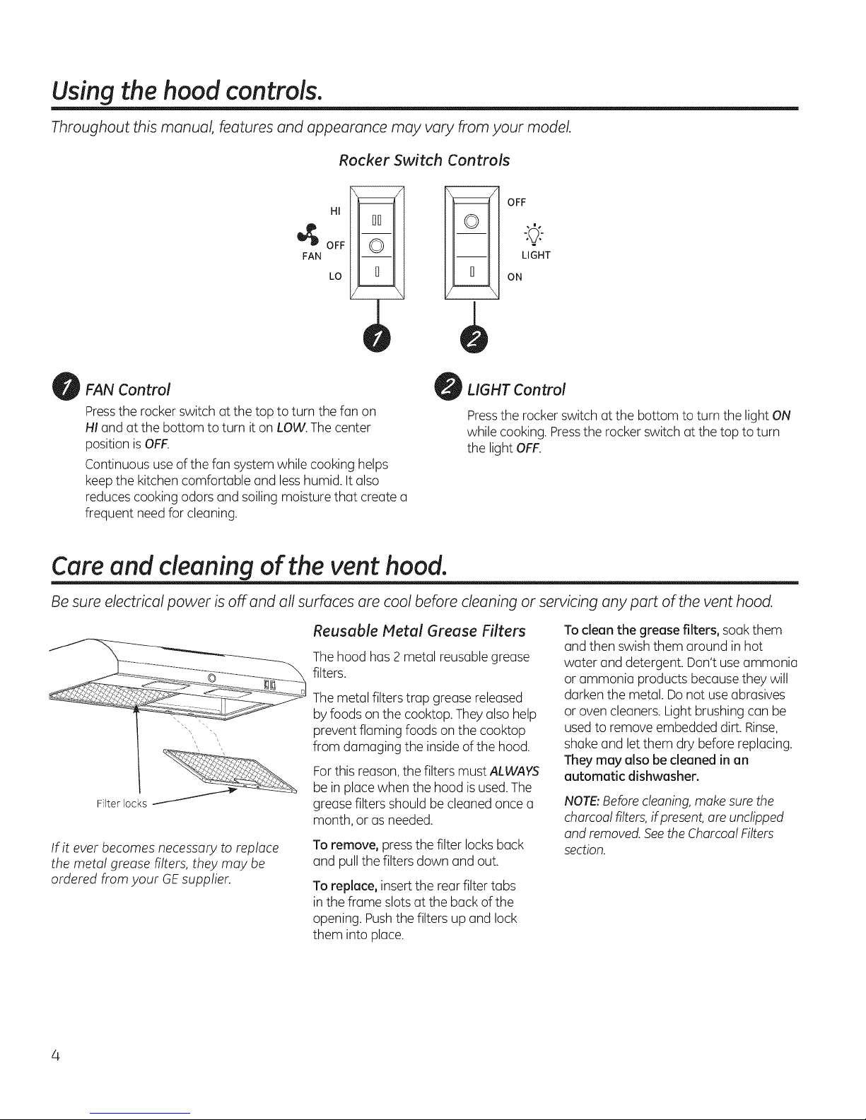
Rocker Switch Controls
HI
00
OFF
FAN
FAN Control
Press the rocker switch at the top to turn the fan on
HIand at the bottom to turn it on LOW.The center
position is OFF.
Continuous use of the fan system while cooking helps
keep the kitchen comfortable and less humid. It also
reduces cooking odors and soiling moisture that create a
frequent need for cleaning.
©
LO
!-!
OFF
LIGHT
0
ON
LIGHT Control
Pressthe rocker switch at the bottom to turn the light ON
while cooking. Pressthe rocker switch at the top to turn
the light OFF.
Care and cleaning of the vent hood.
Be sure electrical power is off and all surfaces are cool before cleaning or servicing any part of the vent hood.
Filter locks
If it ever becomes necessary to replace
the metal grease filters, they may be
ordered from your GE supplier.
Reusable Metal Grease Filters
Thehood has 2 metal reusable grease
filters.
Themetal filters trap grease released
by foods on the cooktop. Theyalso help
prevent flaming foods on the cooktop
from damaging the inside ofthe hood.
Forthis reason,the filters must ALWAYS
be in placewhen the hood isused.The
grease filters should becleaned once a
month, or as needed.
To remove, pressthe filter locksback
and pull the filters down and out.
To replace, insert the rear filter tabs
in the frame slotsat the back of the
opening. Pushthe filters up and lock
them into place.
To clean the grease filters,soak them
and then swishthem around in hot
water and detergent. Don't useammonia
or ammonia products because they will
darken the metal. Donot useabrasives
or oven cleaners.Light brushing can be
usedto remove embedded dirt. Rinse,
shake and letthem dry before replacing.
They may also be cleaned in an
automatic dishwasher.
NOTE:Beforecleaning,make surethe
charcoal filters,if present, are unclipped
and removed.Seethe CharcoalFilters
section.
Page 5
Care and cleaning of the vent hood. GEAppliances.com
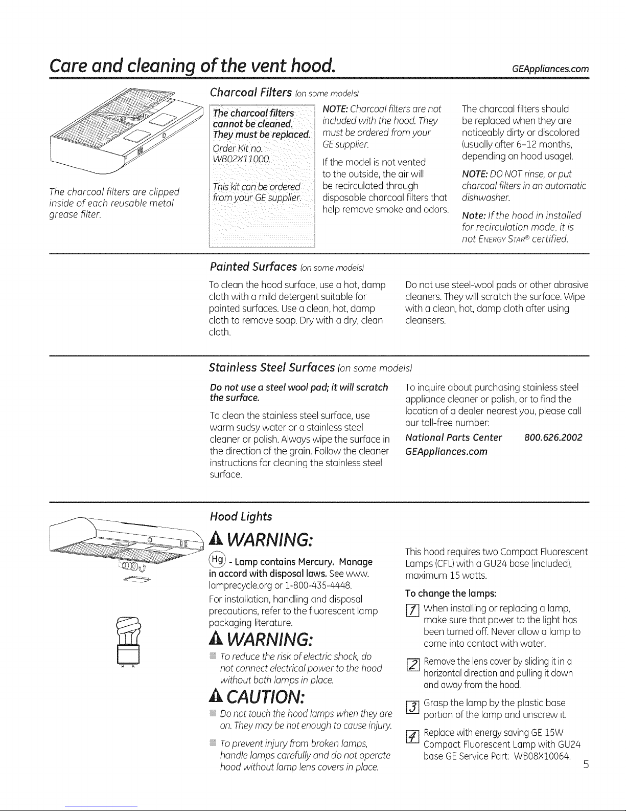
Charcoal Filters (onsomemodels)
The charcoal filters are clipped
inside of each reusable metal
grease filter.
NOTE:Charcoalfilters are not
cannot be cleaned.
They must bereplaced.
Order Kitno.
WBO2X11000
Thiskit canbeordered
from your GEsupplier.
Painted Surfaces (onsome models)
included with the hood.They
must be ordered fromyour
GEsupplier.
Ifthe model isnot vented
to the outside,the air will
be recirculated through
disposable charcoal filters that
help remove smoke and odors.
Thecharcoal filters should
be replaced when they are
noticeably dirty or discolored
(usually after 6-12 months,
depending onhood usage).
NOTE:DONOTrinse,or put
charcoal filters in an automatic
dishwasher.
Note: If the hood in installed
for recirculation mode, it is
not ENERGY STAR@certified.
Toclean the hood surface, use a hot, damp
cloth with a mild detergent suitablefor
painted surfaces.Usea clean,hot, damp
cloth to removesoap. Dry with a dry, clean
cloth.
Stainless Steel Surfaces (on some models)
Do not use a steel wool pad; it will scratch
the surface.
Toclean the stainlesssteelsurface, use
warm sudsywater or a stainlesssteel
cleaner or polish.Always wipe the surface in
the direction of the grain. Followthe cleaner
instructions for cleaning the stainless steel
surface.
Hood Lights
A WARNING:
- Lamp contains Hercury. Hanage
in accord with disposal laws. Seewww.
lamprecycle.orgor 1-800-435-4448.
For installation, handling and disposal
precautions, refer to the fluorescent lamp
packaging literature.
A WARNING:
Toreducethe risk ofelectric shock,do
not connect electricalpower to the hood
without both lamps inplace.
A CAUTION:
Donot touchthehood lamps whenthey ore
on.Theymay be hot enough to causeinjury.
Topreventinjury from brokenlamps,
handle lamps carefullyand do not operate
hood without lamp lenscovers in place.
Do not use steel-wool pads or other abrasive
cleaners.They will scratch the surface. Wipe
with a clean, hot, damp cloth after using
cleansers.
Toinquire about purchasing stainlesssteel
appliance cleaner or polish,or to find the
location of a dealer nearest you, please call
our toll-free number:
National Parts Center 800.626.2002
GEAppliances.com
Thishood requires two Compact Fluorescent
Lamps (CFL)with a GU24 base (included),
maximum 15watts.
Tochange the lamps:
[] When installing or replacing a lamp,
make sure that power to the light has
been turned off. Neverallow a lamp to
come into contact with water.
[_ Removethe lenscoverby slidingit ina
horizontaldirectionand pullingit down
and awayfrom thehood.
I-_ Graspthe lamp by the plastic base
portion of the lamp and unscrew it.
[] Replacewith energysavingGE15W
Compact Fluorescent Lampwith GU24
base GEServicePart: WBO8XlO064.
Page 6
Installation
Ra ge ood
Instructi
Questions? Call 800.GE.CARES (800.432.2737) or Visit our Website at: GEAppliances.com
BEFORE YOU BEGIN
Read these instructions completely and carefully.
.IMPORTANT - Savetheseinstructionsfor
local inspector's use.
" IMPORTANT - Observe all governing
codes and ordinances.
, Note to Installer - Be sure to leave these
instructions with the Consumer.
, Note to Consumer - Keepthese instructions
for future reference.
, Skill level - Installation of this appliance requires
basic mechanical and electrical skills.
, Completion time - 1-3 hours
, Proper installation isthe responsibility of the installer.
, Product failure due to improper installation is not
covered under the Warranty.
FORYOUR SAFETY:
A WARNING - Beforebeginningthe
installation, switch power off at service panel and lock the
servicedisconnecting means to prevent power from being
switched on accidentally. When the servicedisconnecting
means cannot be locked, securelyfasten a prominent
warning device, such as a tag, to the service panel.
A WARNING - ToREOUCETHERISK
OFFIRE,ELECTRICSHOCKOR INJURY TOPERSONS,
OBSERVETHEFOLLOWING:
A. Installationwork and electricalwiring mustbe done by
qualifiedperson(s)inaccordancewith allapplicablecodes
and standards,includingfire-rated construction.
B. Sufficientair isneededfor propercombustion and
exhaustingof gasesthroughthe flue(chimney)of fuel
burningequipmentto preventbackdrafting.Followthe
heatingequipmentmanufacturer'sguidelineand safety
standardssuchas those publishedby the NationalFire
ProtectionAssociation(NFPA),theAmericanSocietyfor
Heating,Refrigerationand Air ConditioningEngineers
(ASHRAE)and the localcodeauthorities.
C. Whencutting ordrillinginto wall or ceiling,do notdamage
electricalwiring and other hiddenutilities.
D. Ductedfansmust alwaysbeventedto the outdoors.
A WARNING- TOREDUCETHERISKOFFIREAND
TOPROPERLYEXHAUSTAIR,BESURETODUCTAIROUTSIDE-
DONOTVENTEXHAUSTAIRINTOSPACESWITHINWALLSOR
CEILINGSORINTOATTICS,CRAWLSPACESORGARAGES.
DUCTWORK REQUIREMENTS
NOTE:Read the ductwork sections only if you do not have
existing ductwork. If you have existing ductwork, skip to
the "Damage" section end proceed.
The venting system must exhaust to the outside,
This hood can be vented vertically through upper cabinets
or horizontally through an outside wall. Ductwork isnot
included.
Exhaust connection:
The hood exhaust has been designed to mate with
standard 3¼" x 10"rectangular ducting.
If a 7" round duct is required, a rectangular-to-round
transition adaptor must be used*. Do not use less then a
7" diameter duct.
Maximum duct length:
Forsatisfactory air movement, the total duct length of a
3¼"x 10" rectangular should not exceed 65 equivalent feet.
NOTE:It's important that ducting be installed using the
most direct route and with as few elbows as possible.
This ensures clear venting of exhaust and helps prevent
blockages. Also, make sure dampers swing freely and
nothing is blocking the ducts.
Elbows, transitions, wall and roofcaps, etc.,
present additional resistance to airflow and are equivalent
to a section of straight duct longer than their actual
physical size.When calculating the total duct length, add
the equivalent lengths of all transitions and adaptors plus
the length of all straight duct sections. The charts onthe
following pages show you how to calculate total equivalent
ductwork length using the approximate feet of equivalent
length of some typical ducts.
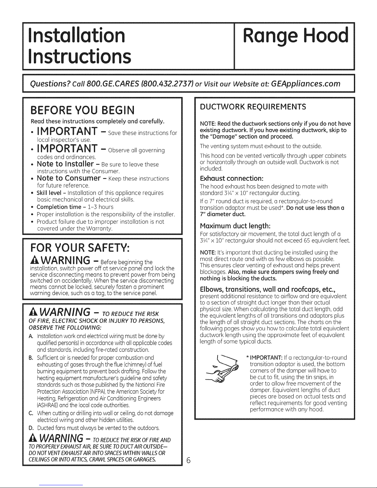
* IMPORTANT:Ifa rectangular-to-round
transition adaptor isused, the bottom
corners of the damper will have to
be cut to fit, using the tin snips,in
order to allow free movement of the
damper. Equivalent lengths of duct
pieces are based on actual tests and
reflect requirements for good venting
performance with any hood.
6
Page 7
Installation Instructions
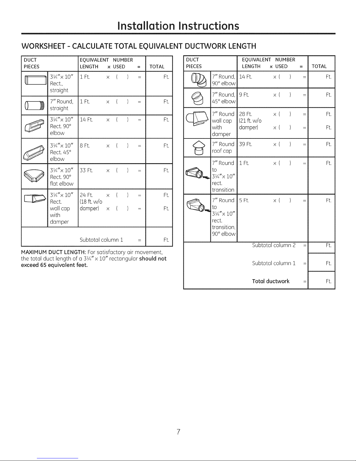
WORKSHEET - CALCULATE TOTAL EQUIVALENT DUCTWORK LENGTH
DUCT
PIECES
3¼"x i0"
Rect.,
straight
7" Round,
straight
3¼"x 10"
Rect.90°
elbow
3¼"x 10"
Rect. 85 °
elbow
l_ 3¼"x !0" 33 Ft. x ( ) = Ft.
MAXIMUM DUCT LENGTH: Forsatisfactory air movement,
the total duct length of a 3¼" x 10" rectangular should not
exceed 65 equivalent feet.
Rect. 90 °
flat elbow
3¼"x !0"
Rect.
wall cap
with
damper
EQUIVALENT NUMBER
LENGTH x USED
! Ft. x ( )
! Ft. x ( )
14 Ft. x ( )
8 Ft. x ( )
24 Ft. x (
(18ft.w/o
damper) x (
Subtotal column i = Ft.
= TOTAL
= Ft.
= Ft.
= Ft.
= Ft.
t =
Ft.
Ft.
DUCT
PIECES
7" Round,
%
G
(_,_ 7" Round 5 Ft. x ( ) = Ft.
90°elbow
7" Round,
45°elbow
7" Round
wall cap
with
damper
7" Round
roof cap
to
3¼"x i0"
rect.
transition
to
3¼"x !0"
rect.
transition
90 ° elbow
EQUIVALENT NUMBER
LENGTH x USED
14 Ft. x ( )
9 Ft. x ( )
28 Ft. x ( )
(21ft.w/o
damper) x( )
39 Ft. x ( )
i Ft. x ( )7" Round
Subtotal column 2 = Ft.
Subtotal column 1 = Ft.
= TOTAL
= Ft.
= Ft.
= Ft.
= Ft.
= Ft.
= Ft.
Total ductwork = Ft.
7
Page 8
Installation Instructions
DAMAG E-SH IPM ENT/I NSTALLATIO N
, If the unit is damaged inshipment, return the unit to the
store in which it was bought for repair or replacement.
, If the unit is damaged bythe customer, repair or
replacement isthe responsibility of the customer.
If the unit isdamaged bythe installer (ifother than
the customer), repair or replacement must be made
by arrangement between customer and installer.
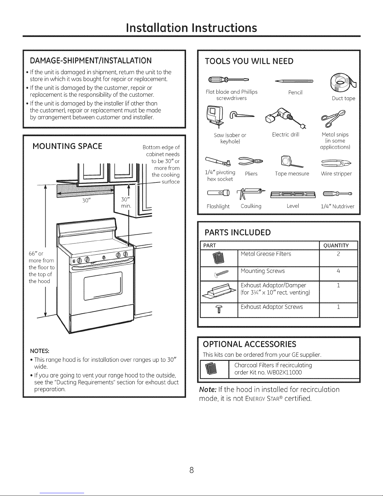
MOUNTING SPACE
Bottom edge of
cabinet needs
to be 30" or
more from
the cooking
TOOLS YOU WILL NEED
Flatbladeand Phillips Pencil
screwdrivers
Saw(saberor Electricdrill
keyhole)
!/4" pivoting Pliers Tapemeasure
hexsocket
Flashlight Caulking Level !/4" Nutdriver
Duct tape
Metalsnips
(in some
applications)
Wire stripper
PARTS INCLUDED
66" or
morefrom
thefloor to
thetop of
the hood
J
NOTES:
, This range hood is for installation over ranges up to 30"
wide.
If you are going to vent your range hood to the outside,
seethe "Ducting Requirements" section for exhaust duct
preparation.
PART QUANTITY
Metal Grease Filters 2
_ Mounting Screws 4
(for 3W' x !0" rect.venting)
ExhaustAdaptor/Damper 1
I_ ExhaustAdaptor Screws 1
OPTIONAL ACCESSORIES
This kits can be ordered from your GEsupplier.
Charcoal Filters If recirculating
order Kit no.WBO2X11000
Note: tf the hood in installed for recirculation
mode, it is not ENERGYSTAR® certified.
8
Page 9

Installation Instructions
CHOOSE VENT OPTION
Determine the vent option that your installation will require
from the following choices:
Theoutside vent exhaust option that your installation
requires will determine the hood knockouts that you
will use.
IMPORTANT:Ifthe hood is to be installed in a recirculating,
non-vented ductless manner, do not knock out any vent
openings in the hood. Onlyan electrical access hole will be
knocked out of the hood.
Outside top exhaust
(Vertical duct-3¼" x 10" Rectangular)
_Outside rear exhaust 10"
(Horizontal duct-3V/' x Rectangular)
Recirculating
(Non-vented ductless-Optional)
\
\
\
\
9
Page 10
Installation Instructions
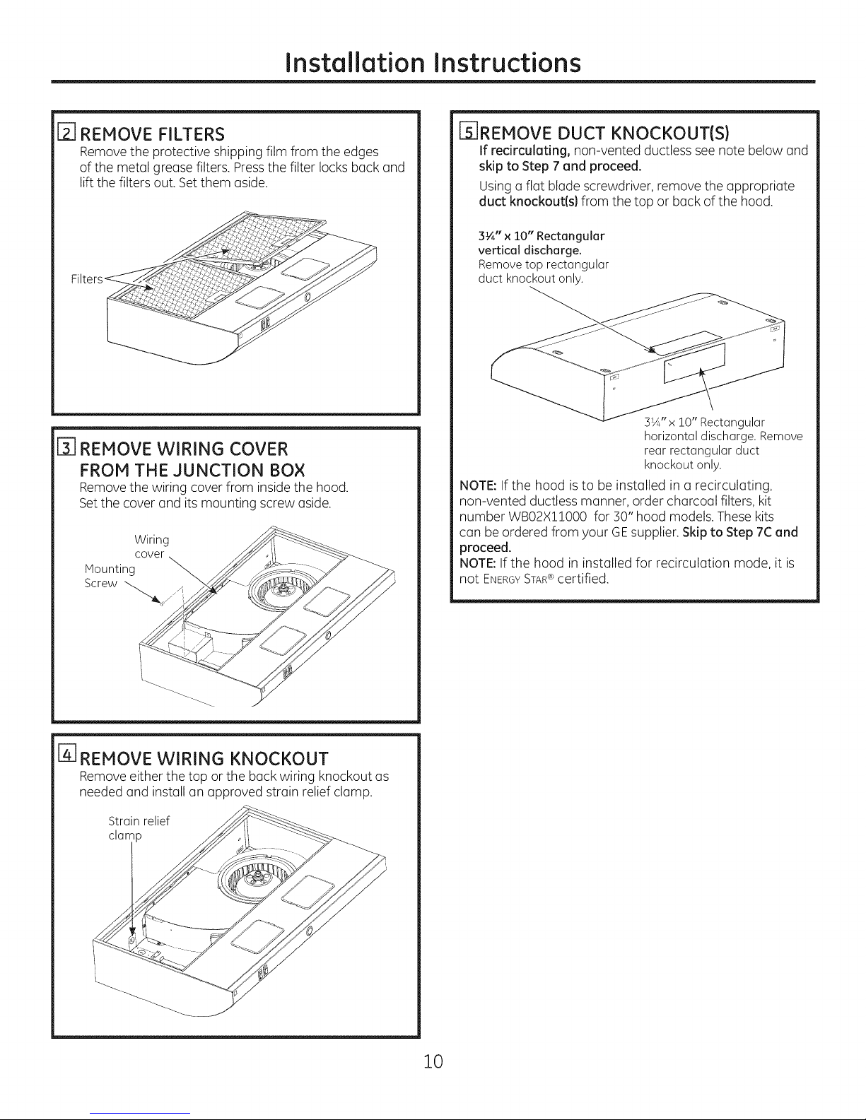
_-I REMOVE FILTERS
Removethe protective shipping film from the edges
of the metal grease filters. Pressthe filter locks back and
lift the filters out. Setthem aside.
[] REMOVE WIRING COVER
FROM THE JUNCTION BOX
Removethe wiring cover from insidethe hood.
Setthe cover and its mounting screw aside.
Wiring
cover
Mounting
Screw "-_._ .
_-IREMOVE DUCT KNOCKOUT(S)
If recirculating, non-vented ductless see note below and
skip to Step 7 and proceed.
Using a flat blade screwdriver, remove the appropriate
duct knockout(s) from the top or back of the hood.
3¼" x 10" Rectangular
vertical discharge.
Remove top rectangular
duct knockout only.
3¼" x !0" Rectangular
horizontal discharge. Remove
rear rectangular duct
knockout only.
NOTE:Ifthe hood is to be installed in a recirculating,
non-vented ductless manner, order charcoal filters, kit
number WB02X!!000 for 30" hood models. These kits
can be ordered from your GEsupplier. Skip to Step 7C and
proceed.
NOTE:If the hood in installed for recirculation mode, it is
not ENERGYSTAR@certified.
[_ REMOVE WIRING KNOCKOUT
Removeeither the top or the back wiring knockout as
needed and install an approved strain relief clamp.
Strain relief
clamp
10
Page 11

Installation Instructions
[_] FOR 3¼"x :10" RECTANGLE DUCTED
DISCHARGE INSTALLATIONS:
Attach exhaust adaptor/damper over knockout
opening with two exhaust adaptor screws. Hake sure
damper pivot is nearest to top/back edge of hood.
Removetape from damper flap.
Up to !" side-to-
side adjustment
Exhaust adaptor/damper
(vertical discharge position
shown)
NOTE:The exhaust adaptor/dumper can be installed
up to 1 inch on either side of the hood center to
accommodate off-center ductwork. In extreme off-center
installations, one end of the duct connector may need to
be trimmed to clear the electrical cable clamp.
Ffl
MARK HOLES
Select the vent option that your installation will require
and proceed to that section:
A. Outside top exhaust
(Vertical duct-3¼" x iO" Rectangular}
. Use the diagram or the hood as a template and mark
the locations on the cabinet for ductwork, electrical
wiring and keyhole screw slots.
Hood mounting screws (4)
13¾" IPA"
ge
Wood shims _ Electrical access
(recessed-bottom ll/16" hole (in cabinet
cabinetsonly) line
Center bottom)
B. Outside rear exhaust
(Horizontal duct-3¼" x lO" Rectangular}
. Use the diagram or the hood as a template and mark
the locations on the cabinet for ductwork, electrical
wiring and keyhole screw slots.
Wood shims (recessed-bottom cabinets only)
_-- 5½"
lPA"
Hood mounting
screws (4) Center line
C. RedrcuJating (non-vented ductless}
. Use the hood as a template and mark the locations
on the cabinet for the electrical wiring and keyhole
screw slots.
. Since the hood is to be recirculated (not to be vented
outside), do not cut out any vent openings in the wall
or cabinet bottom.
11
Cabinet
bottom
Electrical
access hole
(in wall)
Page 12

Installation Instructions
[_ CHOOSE VENTING OPTION
Thehood can be set to vent outside or to recirculute air
back into the kitchen.
. Tovent to the outside, refer to steps 5 and 6.
, To recirculate air into the kitchen, remove two
screws securing the duct block off plate. Discard
plate. Replacetwo screws.
Note: Hood isENERGYSTAR®certified only when it vents
air to the outside.
r9] FOR RECESSED-BOTTOM CABINETS
ONLY
[] RUN WIRES
Runthe electrical wires through the wall or cabinet
according to National Electrical Code and applicable
local codes.
NOTE:DO NOTturn the power on until installation is
complete.
Drive a mounting screw (from the hardware packet)
r_] SCREW IN PARTWAY
partway into each center of the narrow neck of the
keyhole slots marked on the cabinet bottom.
FEED IN WIRES
Lift the hood into position and feed the house
wiring through the wiring knockout.
[_] SECURE HOOD
Slide the hood back against the wall. Tighten the
mounting screws. Be sure the screw heads are in
the narrow neck of the keyhole slot.
Woodshims
. If the cabinets have front, side or back trim, make
2 wood shims the width of the trim and attach them to
the cabinet bottom recess on both sides. SeeStep 7 for
marking locations.
[_] CUT HOLES
Cut holes at marked locations for duct and electrical
wiring. Forthe vertical duct, cut out 3/4" extra toward
the front of the cabinet so you can move the duct
freely when installing the hood. It may also ease
installation by cutting the hole !0½" instead of !0".
Keyhole (4)
12
Page 13

Installation Instructions
i-_ CONNECT DUCTWORK TO HOOD
Use duct tape to make joints secure and air tight.
Note: Illustration shows rectangular to round ducl adapter.
[16] INSTALL LAMPS
A WARNING:
(_- Lamp contains Mercury. Manage in accord with
disposal laws. See www./amprecyc/e.org or 1-800-435-4448,
For installation, handling and disposal precautions, refer to
the fluorescent lamp packaging literature.
A WARNING:
Toreduce the risk of electric shock, do not connect electrical
power to the hood without both lamps in place.
A CAUTION:
Do not touch the hood lamps when they are on. They may
be hot enough to cause injury.
Toprevent injury from broken lamps, handle lamps carefully
and do not operate hood without lamp lens covers in place.
This hood requires two Compact Fluorescent Lamps (CFL)
with a GU24 base (included), maximum J_5watts.
To change the lamps:
E_ When installing or replacing a lamp, make sure that
power to the light has been turned off. Never allow a
lamp to come into contact with water.
[] Remove the lens cover by sliding it in a horizontal direction
and pulling it down and away from the hood.
rJ] Grasp the lamp by the plastic base portion of the lamp
and unscrew it.
i_] FOLLOW ELECTRICAL CODE
Complete the electrical wiring according to National
Electrical Code and local codes.
NOTE: This hood must be permanently grounded.
Connect house wiring (120 VAC) to hood wiring.
CONNECT WIRING
Connect house black to hood black wire, house white
to hood white wire, and house ground to hood green/
yellow wire. Securely tighten the strain relief clamp
onto the house wiring.
[_ REPLACE WIRING COVER
Replace the wiring cover.
/<
[_ REPLACE FILTERS
The installation is complete. Turn on power at service
panel, and test for proper operation.
[] Replacewith energy saving GE15W Compact Fluorescent
Lump with GU24 bose GEService Part: WBO8X10064.
TROUBLESHOOTING CHECKLIST
If the hood seems to be operating at high speed when
the control is not set on high, or if ventilation seems
inadequate, check the following:
GI Knockouts not removed from hood.
GI Damper blade not opening.
GI Reduced airflow because the duct is too small or the
duct length is too long.
GI The duct is blocked.
GI Undersized or restrictive wall or roof cap.
13
Page 14

Before you call for service...
Troubleshooting Tips
Save time and money! Review the following chart first
and you may not need to coil for service.
Possible Causes What To Do
Fan doesnot operate A fuse may be blown or a . Replace fuse or reset circuit breaker.
whenthe switchison circuit breaker may be tripped.
Fan fails to circulate air
or moves air more slowly
than normal
Fan continually cycles
off and on
Compact Fluorenscent This is normal for Compact . Allow lamp to run for several minutes. Ifthis warm up
Lamp appears dim Fluorescent Lamps especially time does not solve the problem replace the lamp.
on start up on first installation.
Compact Fluorescent This is normal for Compact . Allow lamp to run for several minutes.
Lamp briefly Fluorescent Lamps If this warm up time does not solve the problem
flickers on start up especially on first installation, replace the lamp.
After replacing one
lamp, the new lamp
appears to be a
different color
Excessively soiled filter.
The motor is probably
overheating and turning itself
off. This can be harmful to
the motor. Filter may be
excessively soiled.
The replacement lamp may
have a different color
temperature rating :i.e. is
3000K instead of 2700K.
The replacement lamp may
be from a different
manufacturer.
Wash and replace the filters. See the Reusable
Metal GreaseFilterssection.
Replace the filter if it istoo soiled to clean. If it
is not soiled, or if replacing the filter does not
solve the problem, call for service.
Replace the filter if it is soiled. If it is not soiled,
or if replacing the filter does not solve the problem,
call for service.
. Use a GE15W GU24 base lamp with a 2700K rating.
GEService Part number WB08X10064.
. Use a GE15W GU24 base lamp with a GE Service Part
number WB08X!0064.
14
Page 15

GE Range Hood Warranty.
All warranty service provided by our Factory Service Centers,
or an authorized Customer Care®technician. Toschedule service
on-line, visit us at GEAppliances.com, or call 800.GE.CARES
(800.432.2737). Please have serial number and model number
available when calling for service.
Stapleyour receipt here.
Proof of the original purchase
date is needed to obtain service
under the warranty.
GE Will Replace:
One Year Any part of the range hood which fails due to a defect in materials or workmanship.
From thedate Ofthe During thislimited one-year warranty, GEwill also provide, free of charge, all labor and
OriginalpOrchase in-home service to replacethe defectivepart.
Service trips to your home to teach you how to use
the product.
Improper installation, delivery or maintenance.
Product damage or failure of the product if it isabused,
misused, modified, used for other than the intended
purpose, or used commercially.
Replacement of house fuses or resetting of circuit breakers.
Damage to the product caused by accident, fire, floods
or acts of God.
Incidental or consequential damage caused by possible
defects with this appliance.
Damage caused after delivery.
Product not accessible to provide required service.
EXCLUSION OF IMPLIED WARRANTIES--Your sole and exclusive remedy is product repair as provided
in this Limited Warranty. Any implied warranties, including the implied warranties of merchantability
or fitness for a particular purpose, are limited to one year or the shortest period allowed by law.
This warranty is extended to the original purchaser and any succeeding owner for products purchased for home
use within the USA. If the product is located in an area where service by a GEAuthorized Servicer is not available, you
may be responsible for a trip charge or you may be required to bring the product to an Authorized GEService Location for
service. In Alaska, the warranty excludes the cost of shipping or service calls to your home.
Some states do not allow the exclusion or limitation of incidental or consequential damages. This warranty gives
you specific legal rights, and you may also have other rights which vary from state to state. To know what your
legal rights are, consult your local or state consumer affairs office or your state's Attorney General.
Warranton General Electric Company. Louisville, KY 40225
15
Page 16

Consumer Support.
GE Appliances Website GEAppliunces.com
Have a question or need assistance with your appliance? Try the GEAppliancesWebsite 24 hours a day,
any day of the year! Forgreater convenience and faster service,you can now download Owner's Hanuals,
order parts or even scheduleservice on-line.
Schedule Service GEAppliances.com
ExpertGErepair service isonly one stepaway from your door. Geton-line and scheduleyour service at
your convenience any day of the year! Or call800.GE.CARES(800.432.2737)during normal businesshours.
Real Life Design Studio GEAppliances.com
GEsupports the UniversalDesignconcept---products, servicesand environments that can be used by
people of all ages,sizesand capabilities.We recognize the need to design for a wide range of physical and
mental abilities and impairments. For details of GE'sUniversalDesignapplications, including kitchen design
ideasfor peoplewith disabilities,check out our Website today. For the hearing impaired, please call 800.TDD.
GEAC(800.833.4322).
Extended Warranties
Purchasea GEextended warranty and learn about special discounts that are available while your warranty
isstill in effect.You can purchase it on-line anytime, or call 800.626.2224during normal businesshours.
GEConsumer Home Serviceswill still be there after your warranty expires.
Parts and Accessories
Individualsqualified to servicetheir own appliances can have parts or accessoriessent directly to their homes
(VISA,HasterCard and Discovercards are accepted).Order on-line today, 24 hours everyday or
by phone at 800.626.2002 during normal business hours.
Instructions contained in this manual cover procedures to be performed by any user. Other servicing
generally should be referred to qualified service personnel. Caution must be exercised, since improper
servicing may cause unsafe operation.
Contact Us
Ifyou are not satisfied with the serviceyou receive from GE,contact uson our Websitewith all the details
includingyour phone number, or write to: GeneralManager,Customer Relations
GEAppliances,Appliance Park
Louisville,KV40225
GEAppliances.com
GEAppliances.com
GEAppliances.com
Register Your Appliance GEAppliances.com
Register your new appliance on-line---at your convenience! Timelyproduct registration will allow for
enhanced communication and prompt service under the terms of your warranty, should the need arise.
You may also mail in the pre-printed registration card included in the packing material.
16
Page 17

0
0
GEAppliances.com
InformaciGn de seguridad.. 2
Instrucciones de operaciGn /
Cuidado y limpieza
controles de ventilaciGn .......... 3
Filtros de carb6n ................. 4
Filtros para la grasa .............. 3
Luces de la campana ............ 4
Superficies de
acero inoxidable ................. 4
Superficies de la campana ....... 4
Instrucciones
de instalaciGn .............. 5-12
Solucionar problemas ...... 13
JVE40
Soporte al consumidor
soporte al consumidor .......... 16
Garantia ........................ 15
*Producto rotulado como ENERGYSTAR®
ENERGYSTAR
Como un socio de ENERGYSTAR ®,
GEha determinado que este
producto cumple con I(]s normas
de ENERGYSTAR®per(] un uso
eficiente de I(] energi(].
Escriba el modelo y n_mero de
serie uqui:
N_mero de modelo
N_mero de serie
Estos nSmeros se encuentron en uno
etiqueto en Io pored posterior de Io
compono.
Impreso en China
49-80622-1 08-11 GE
Page 18

INSTRUCCIONES DE SEGURIDAD ihIPORTANTES.
LEA TODAS LAS INSTRUCCIONES ANTES DE USAR.
PRECAUCIONESDE SEGURIDAD
A ADVERTENCIA- PARAREOUCIR
EL RIESGODE INCENDIOS, DESCARGASELECTRICAS
0 LESIONESPERSONALES,OBSERVELO SIGUIENTE:
A Useesteunidad solamentede lamaneraque elfabricante Ioindique.
Siustedtiene preguntas, p6ngaseen contacto conel fabricante.
B. Antesde proporcionarservicioo de limpiarla unidad,desconecteet
suministroel@ctricoen elpanelde servicioy cierreelmecanismo de
seguridadpara evitar que alguien Ioconecte accidentalmente.Cuando
no existaun dispositivode cierrede seguridad,amarre unaviso visible,
como unaetiquetaalpaneldeserviciohaciendo la advertencia.
C. No useesta unidadcon ning0n dispositivode control develocidadde
estados61ido.
D. Estaunidaddebe estar conectadaatierra.
a,PRECAUCION- Parausodeventitacidngeneraf
sofamente.No usepara exputsarmateriatespetigrososo expfosivos
y vapores.
A ADVERTENCIA- PARAREDUCIR
EL RIESGODE LESIONESPERSONALESEN EL CASODE UN
INCENDIO DEBIDO A GRASADE ESTUFAQUEHADA, HAGA LO
SIGUIENTE*:
A. CONTENGALASLLAMAScon unatapa queajustebien sobrela sart@n,
con una I@minapara hacerdulceso con una bandeja met@lica,y luego
apagueet quemador.TENGACUIDADODENOQUENARSE.
Silasllamas nose apagan inmediatamente,EVACUEELLUGARY
LLAMEALDEPARTAMENTODEBOIVlBEROS.
B. NUNCAAGARREUNASARTENOUNAOLLAQUESEENCUENTREEN
LLANAS-Sepodria quemar.
C. NOUSEAGUA,incluyendopaBosde cocinaotoallas humedecidas-
estohar@que ocurra una explosi6ndevapor violenta.
D. Useun extintorSOLANENTEsi:
1. Ustedsabeque tiene un extintor ClaseABC,y si ustedya sabe
c6mo operarlo.
2. Elfuego es pequer_oy est@contenidoal @eadonde comenz6.
3. Eldepartamento de bomberoshasidoItamado.
4. Ustedest@luchandocontra lasllamas con susespaldashacia una
salida.
* Basadoen "KitchenFireSafety",publicadoporNFPA.
A ADVERTENCIA- PARAREOUCIR
EL RIESGODE UN FUEGODE GRASADE ESTUFA:
A. Nunca dejeunidadesde superficiessin la atenci6ndebida en
seleccionesaltas.Cuandose est5hirviendo algoy ocurren
derramamientos,estospodriancausar humoy que los
derramamientosgrasososseincendien.Calientelosaceites
lentamentea seteccionesmediasy bajas.
B. Siempreenciendalacampana cuando cocineafuego alto ocuando
flambeealimentos(CrepesSuzette,CherriesJubilee,Flambeadode
Camecon Pimienta).
C. Limpieel ventiladorconfrecuencia. Lagrasa no debeacumularseen et
ventiladoro en elfittro.
D. Useuna sart@ndetamar_oapropiado.Siempreusepiezasdecocina
apropiadaspara ettamar_odelelementode lasuperficie.
ADVERTENCIA- PARAREDUCIREL RIESGODE
INCENDIOS, DESCARGASELE-CTRICAS0 LESIONESPERSONALES,
OBSERVELO SIGUIENTE:
A. Eltrabajo deinstalaci6ny elalambrado el@ctricodebehacerlo una
persona(s)calificadaconforme a todos
losc6digosy est@ndaresaplicables,incluyendounaconstrucci6n
aprobada pot etinspector deincendios.
B. Suficienteairees necesariopara una combusti6napropiada y para
deshacersede losgasesatrav@sde una salidade humo (chimenea)
de equiposquequeman combustiblespara prevenirretroalimentaci6n.
Sigalas recomendacionesdelfabricante delequipo decalentamiento
y los est6ndaresde seguridadtales como lospublicadospot la
Asociaci6nnacional deprotecci6nde incendios(NFPA),y laSociedad
americana deingenierosde calefacci6n,acondicionadoresde airey
refrigeraci6n(ASHRAE),y losc6digos de lasautoridadeslocales.
C. Cuandose encuentrecortando o taladrandoen la pared o enel techo,
no dar_elos alambradoset@ctricosu otras utitidadesescondidas.
D. Losventiladorescon conductosdebenestar siempreventiladoshacia
el exterior.
,_ADVERTENCIA- PARAREDUCIRELRIESGO
DE INCENDIO Y PApAQUE EL AIRESE VENTILEDE MANERA
ADECUADA,ASEGURESEDEQUEELAIRESALGAAL EXTERIOR-NO
VENTILEAIRE DEESCAPEEN ESPAC!OSDENTRODE PAREDES
0 CIELORRASOS0 DENTRODE,_TICOS,HUECOSSANITARIOS0
GARAJES.
LEAYSIGAESTAINFORMACIONDESEGURIDADCUIDADOSAMENTE
GUARDE ESTAS INSTRUCCIONES
^,_ADVERTENCIA- PARAREOUCIRELRIESGO_E
INCENDIOS,SOLAHENTE USECONDUCTOS 1'4ETALICOS.
No intentereparar o reemplazarninguna parte desu estufa de
ventilaci6ndeaire descendente(down@aft)a no setque Io recomiende
especificamenteestemanual. Cualquierotro serviciodebeser referidoa
un t@cnicocalificado.
Page 19

Uso de los controles de la campana.
A Io largo de este manual, los funcionesy el aspecto pueden ser diferentes a los de su modelo.
Controles interruptores de presi6n (enaOunos modelog
GEAppliances.com
HI
D
OFF
LO
©
I
FAN
Control del VENTILADOR
Presioneelinterruptoren lapartesuperiorparaencenderel
ventiladorenlavelocidadalta(HI)yen laparteinferiorpara
reducirloabajo(LOW).Enla posici6ncentralquedaapagado
(OFF).
m
OFF
0
LIGHT
[
ON
Control de Io LUZ
Presioneelinterruptoren lapartesuperiorparaencenderlaluz
(ON)mientrasestacocinando.Presioneelinterruptoren laparte
deabajoparausarcomoluzpor lanoche.
Laposici6ncentralindicaqueestaapagada(OFF).
Elusocontinuodelsistemadeventilaci6nmientrascocina
ayudaa mantenerla cocinaagustoy menosh0meda.Tambi6n
reducelosoloresdecocci6nyla humedadqueproduce
manchasy creanunanecesidadfrecuentedelimpieza.
Cuidado y limpieza de la campana de ventilaci6n.
Cerci6rese de que la corriente eldctrica estd apagada y todas los superficies estdn frias antes de limpiar o
realizar mantenimiento acualquier porte de la campana de ventilaci6n.
Si fuese necesario reemplazar los filtros
metdlicos para la grasa, los puede
ordenar a travds de su proveedor GE.
Filtros met61icos reutilizables para
LGcampana tiene dos filtros metc_licos
reutilizables.
Losfiltros metc_licosatrapan la grasa que
liberan los alimentos en la superficie de
la estufa. Tambi6n ayudan a evitar que
losalimentos en llamas que estc_nen la
superficie de la estufa da_en en interior
de la campana.
Poresta raz6n, losfiltros SIEMPRE
deben estar ensu lugar cuando seusa
la campana. Losfiltros para la grasa se
deben limpiar una vez al mes,o segOn
sea necesario.
Para retirarlos, presionelos bloqueosdel
filtro hacia atrc_sy hale losfiltros hacia
abajo y hacia fuera.
Para reemplazarlos, inserte laspestahas
posteriores del filtro en las ranuras
del marco en la parte posterior de la
abertura. Presione losfiltros hacia arriba
y aj0stelosen sulugar.
la grasa
Para limpiar los filtros para la grasa,
rem6jelosy luego agitelosen agua
caliente y detergente. No useamoniaco
o productos basadosen amoniaco
ya que oscurecerc_nel metal. Nouse
abrasivoso limpiadores de homo. Se
pueden cepillar ligeramente para retirar
la suciedad incrustada. Enjuague,agite
y deje secar antes de reemplazar.
Tambi6n se pueden limpiar en la
lavadora de platos autom6tica.
NOTA:Antes de Iimpiar,cerci6resede
que los filtros de carb6n,silos hay,se
desprendany retiren.Consultelasecci6n
Filtrosdecarb6n.
Page 20

Cuidado y limpieza de la campana de ventilaci6no
Filtros de carb6n (analgunos moddos)
NOTA:Los filtros de carb6n
no estdn incluidoscon
la campana. Debenser
ordenados de susuplidor GE.
Siel modelo no tiene
ventilaci6n hacia el exterior, el
aire se recircula a trav@sde los
filtros de carb6n desechables
qua ayudan aevitar el humo y
losolores.
Losfiltros de carb6n se
deben reemplazar cuando
No useesponjillas u otros limpiadores
abrasivosya qua pueden rayar la superficie.
Limpie con un paso limpio, humedecido con
ague caliente despu6sde user limpiadores.
Los filtros de carb6n estdn unidos
al interior de cada filtro metdlico
pare la grasa.
no sepueden limpiar,
sinoquesedeben
reemplazar.
Ordeneel ki[ NO:
WBO2X10707i
EstoS itSSenueden
ordenar a trovdsde
proveedo GE.
Superficies pintadas tenalgunosmoddos)
Pare limpiar la superficiede lacampana, use
un paho humedecido con ague caliente y
detergente suave adecuado pare superficies
pintadas. Useun paho limpio, humedecido
con ague caliente pare retirar eljab6n. Seque
con un paso limpioy seco.
est_n obviamente sucios o
descoloridos(por Io general
despu#s de 6 a 12mesas,
dependiendo del uso de la
campana).
NOTA:NO enjuague,o lave
losfiltros decarb6n en un
lavaplatos automdtico.
Note: Si lacampona se insta-
la en modo de recirculaci6n,
no se encuentra certificada
pot ENERGY STARe.
Superficies de acero inoxidable (analgunos modelos)
No utilice almohadillas de lana de acero
ya que rayar(_ la superficie.
Pare limpiar lasuperficiede acero
inoxidable, utilice aguajabonosa o u
limpiador o pomade pare acero inoxidable.
Siemprelimpie lasuperficie en la direcci6n
del grano. Siga lasinstrucciones del
producto limpiador al limpiar la superficiede
acero inoxidable.
Luces de la campana
AADVERTENCIA:
- La lampara contJenemercurJo.
Maneje de ecuerdo con las leyes de
eliminaci6n.Verwww.lamprecycle.org o
1-800-435-4448.
Pare precaucionessobreinstalaci6n,
manipulaci6n y eliminaci6n,consultela
informaci6n de empaque de la16mpara
fluorescente.
A ADVERTENCIA:
• Pare reducir el riesgode una descarga
eldctrica,no conecte la energfaeldctrica
hacia la campana sinambas Idmparas en
su lager.
Sitiene preguntas sobre la compra de
un limpiador o pomade limpiadora de
electrodom6sticos de acero inoxidable,o
pare averiguar la direcci6n del distribuidor
m@scercano, porfavor llama al siguiente
nOmerotelef6nico gratuito:
Centro nacionel de piezes 800.626.2002
GEAppliances.com
• Poe evitar lesionesprovocadas pot
Idmpams rotes, manipOlelascon cuidado
y no operala campana sin loscubiertasde
losIdmpams en su lager.
Estacampana requiere dos 16mparas
fluorescentes compactas (CFL)con una base
GU24(incluida)de 15vatios como m6ximo.
Pare cembier les 16mparas:
JTJ Cuando instale o reemplace una
16mpara,asegOresede qua la energia
dirigida hacia la luzsehaya apagado.
Nunca permita qua una lampara entre
en contacto con ague.
[] Quitela cubiertade la lampara
deslizandolaunsentido horizontaly
jalandola haciaabajoyen sentido
contrariode la campana.
A PRECAUCION:
Tomela bmpara dela porci6n pbstica de
• No toque losIdmparas de la campana
cuando seencuentren encendidas.
4
Puedenester Io suficientementecalientes
como poe provocar lesiones.
la basede la 16mparay desenr6squela.
Coloqueunalampara fluorescente
compacta GE:I.5Wde bajoconsumocon
la piezadeservicioGEpare baseGU24:
WB08X10064.
Page 21

Instrucci es
Ca
pa
dei stalaci6n
Preguntas? Llama a1800.GE.CARES (800.432.2737) o visite nuestro sitio Web: GEAppliances.com
ANTES DE EIPEZAR
Lee estes instrucciones complete y cuidadosamente.
. IMPORTANTE - Guardeestas
inspectorlocal
-- Observe todos
los c6digos y ordenanzas vigentes.
, Note pare el instalador - cerci6rese de dejar
estas instrucciones en poder del consumidor.
, Note pare el consumidor - lantenga estas
instrucciones pare referencia future.
. Nivel de destrezas - Lo instalaci6n de este operate
requiere de destrezas mec6nicas y el6ctricas b6sicas.
. Tiempo pare la instaleci6n - 1 a 3 horas
. Lainstalaci6n correcta es responsabilidad del
instalador.
. Lafalla del producto debido a una instalaci6n
incorrecta no est6 cubierta par la garant[a.
. Usesolamente con el kit de cable aprobado, JXHC!.
PaR SU SEGURIDAD:
A ADVERTENCIA - Antesdeempezar
con la instalaci6n, desconecte la corriente en el panel
de servicio y bloquee el media de desconexi6n del
servicio para evitar que lacorriente se restablezca
accidentalmente. Cuando el media de desconexi6n del
servicio no se pueda bloquear, fije firmemente al panel
de servicio un dispositivo de advertencia prominente,
coma una etiqueta,
A ADVERTENCIA- PARARE UCIREL
RIESGODEINCENDIOS,DESCARGASELE-CTRICAS0 LESIONES
PERSONALES,OBSERVELOSIGUIENTE:
A.Eltrabojodeinstalad6nyelatambradoet_ctricodebehacerlouna
persona(s)catificadaconformeatodoslosc6digosyest6ndaresapticables,
induyendo una construcd6n aprobada parelinspector deincendios.
B.Suficienteaireesneces(]rioparaunacombusti6nopropiada ypar(]
deshacersedelosgasesatrav6sdeunasalidadehumo(chimenea)
deequipos quequemancombustiblespar(]prevenir retro(]timent(]ci6n.
Sigat(]srecomendodonesdelf(]bric(]ntedelequipodec(]tent(]miento
ylosest6nd(]resdeseguridadtalescomalospublic(]dospart(]
Asoci(]d6nn(]cionaldeprotecd6n deincendios(NFPA),y1(]Sociedad
americanadeingenierosdec(]lef(]cci6n,(]condicionadoresdeairey
refriger(]ci6n(ASHRAE),y losc6digosdet(]s(]utoridadeslocales.
C.Cuandoseencuentrecort(]ndoot(]t(]dr(]ndoenl(]pored o eneltecho,
nodarelos(]l(]mbr(]dosel6ctricosuotr(]sutitidadesescondidas.
D.Losventiladoresconconductosdebenestarsiempre ventitados
haciaelexterior.
REQUISITES PARA LA INSTALACION
DE LOS DUCTOS
NOTA:Lealas secciones de la instalaci6n de losductos 6nicamente
si no tiene una instalad6n de ductos existente. Sitiene una
instalaci6n de ductos existente, siga con la secci6n "Dafios."
El sistema de ventilaci6n debe tener salida al exterior.
Esta campana se puede ventilar verticalmente a trav@sde
los gabinetes superiores u horizontalmente a trav@sde una
pared exterior. Lainstalaci6n de los ductos no est6 incluida.
Conexi6n del escape:
Elescape de la campana est6 diseBado para acoplarse
con ductos estc_ndarrectangulares de :3_" x !0" o ductos
circulates de 7" de di6metro.
Sise requiere de un ducto circular de 6," se debe usar un
adaptador de transici6n rectangular a circular*. No use un
ducto con di6metro inferior a 6."
Longitud m6xima del ducto:
Paraun movimiento satisfactoriodelaire,la Iongitudtotal de
un ducto rectangularde ]_" x 10",circular de 7" de di6metro
no debe superar elequivalente a 65 pies.
NOTA:Esimportante que los ductosseinstalen usando la ruta
m6s directa y con elmenornOmeroposible de codos.Esto
garantiza una ventilaci6ndirecta delescapey ayuda a evitar
lasobstrucciones.Igualmente,cerci6resede que elregulador
de tiro semueva librementey nada obstruya/os ductos.
Cod.as,transiciones, tapes pare pared y
techo, etc,, presentan resistencia adicional al flujo del
aire y son equivalentes a una secci6n de ducto directo m6s
largo que su tamaho fisico real. AI calcular la Iongitud total
del ducto, agregue laslongitudes equivalentes de todas las
transiciones y adaptadores ademds de la Iongitud de todas
lasseccionesrectas del ducto. Lastablas en las pdginas
a continuaci6n muestran c6mo calcular la Iongitud total
equivalente del ducto usando la Iongitud equivalente de pies
aproximados de algunos ductos comunes.
permitir el movimiento libre del regulador de tiro. Las
longitudes equivalentes de las piezas del ducto estc_n
basadas en pruebas reales y reflejan los requisitos para
una buena ventilaci6n con cualquier campana.
pa
* IMPORTANTE:Sise usa un adaptador
de transici6n rectangular a circular, las
esquinas inferiores del regulador de tiro se
tienen que cortar para que encajen, con
unastijeras de hojalata, para poder
estufa
A ADVERTENCIA- PARAREOUC/REL
RIESGODEINCENDIOYPARA OUEELAIRESEVENTILEDE
MANERAADECUADA,ASEGURESEDEOUEELAIRESALGA
ALEXTERIOR-NOVENTILEAIREDEESCAPEENESPAC!OS
DENTRODEPAREDES0 CIELORRASOS0 DENTRODEATICOS,
HUECOS5ANITARIOS0 GARAJES.
Page 22

Instruccionesde instalaci6n
HOJA DE TRABAJO--CALCULE LA LONGITUD TOTAL EQUIVALENTE DEL DUCTO
PIEZAS
DEL DUCTO
0
J
Rectangular,
rectade
3¼"xi0"
Circular,
rectade 7"
Codade 90°
rectangular
de 3_"x i0"
Codade 45°
rectangular
de3¼"×10"
de 90°rect
Codapiano
de 3¼"x 10"
Tapade
paredrect.
de 3W'x i0"
conregubdor
de tiro
LONGITUD NOMERO
EQUIV. x USADO
Zpie
Zpie
Z4pies × ( ) =
8 pies
33 pies × ( ) =
24 pies x (
(18piessin
reguladorde x(
tiro)
x( ) =
x( ) =
x( ) =
)
)
= TOTAL
pies
pies
pies
pies
pies
= pies
= pies
PIEZAS LONGITUD NOMERO
DEL DUCTO EQUIV. x USADO = TOTAL
(_ Codode90° !4 pies x ( ) : pies
C_ apa de 28 pies x ( ) : pies
(__ Codade90° 5 pies x ( ) : pies
circ. de 7"
circ. de 7"
Codade45° 9 pies x ( ) = pies
pared circ. (21piessin
de 7"con reg.detiro) x ( ) = pies
reg.detiro
techo circ
Tapa de 39 pies x ( ) : pies
de 7"
Trans.circ ! pies x ( ) = pies
)_ de 7"a
rect.de
3¼"x !0"
de trans.
circ. de 7"
a rect. de
3¼"x !0"
Subtotal columna 1 : pies
Longitud m6xima del ducto: Para un movimiento
satisfactorio del aire, la Iongitud total de un ducto
rectangular de 3¼" x 10" no debe superar el equivalente a
65 pies.
Subtotal columna 2
Subtotal columna 1
Ducto total
= pies
= pies
= pies
6
Page 23

Instruccionesde instalaci6n
DANOS-ENViOIINSTALACION
. Si la unidad se da_a en el envio, devuelva la unidad a la
tienda donde secompr6 para reparaci6n ocambio.
. Siel cliente da_a la unidad, la reparaci6n o el cambio es
responsabilidad del ciente.
. Siel instalador da_a la unidad (alguien diferente al
cliente),la reparaci6n o el cambio se debe hacer en
un arreglo entre el cliente y el instalador.
ESPACIOPARA INSTALACION
30" iVlh
3O
El borde
inferior
del gabinete
debe tener
una distancia
de 30" o
mas desde
la superficie
de la estufa
HERRAMIENTAS QUE NECESITA
Destornitladordecabezaplana L6piz
ydestornittadordeestretla
Serrucho(devaiv6n Taladroel6ctrico
o segueta)
Cinta para
ductos
Tijerasdehojalata
(enalgunas
aplicaciones)
Boquillahex. Alicates Cintade medir
giratoriade
1/4"
Separador
de cables
Destornillador
Linterna Pistolapara Nivel paratuercasde
sellado !/4"
PARTES INCLUIDAS
66"o mas
desdeelpiso
hasta laporte
superiorde la
carnpana
NOTAS:
. Esta campana es para instalaci6n en estufas hasta de
30" de ancho.
. Sila campana va a ventilarse hacia el exterior, consulte
la secci6n "Requisitospara la instalaci6n de losductos"
para lapreparaci6n del ducto del escape.
PARTE CANTIDAD
Filtros metalicos para la grasa 2
Tornillos para instalaci6n 4
<:__ Adaptador del escape/regulador 1
de tiro (paraventilaci6n rect.
de 3_4"x !0")
Tornillosdeladaptadordelescape 1
ACCESORIOS OPCIONALES
Estoskit se pueden ordenar a trav6s de su proveedor GE.
Filtrosdecarb6nsi realizarecirculaci6n.
ordene Kit No.WB02X!0708.
Note: Si la campana se instala en modo de
recircutaci6n, no se encuentra certificada por
ENERGYSTAR®.
Page 24

Instruccionesde instalaci6n
[Y]SELECCIONE LA OPCION
DE VENTILACION
Determine entre las siguientes opciones la opci6n
de ventilaci6n que su instalaci6n requiere:
Laopci6n de escape de ventilaci6n exterior que su
instalaci6n requiera determinar6 losagujeros ciegos
de la campana necesarios.
Escape superior exterior
(Ducto vertical--3¼" x 10" rectangular)
IMPORTANTE:Sila campana seva a instalar de forma
recirculante,sinductos,sinventilaci6n, no per/oreninguna
abertura de ventilaci6nen la campana. 0nicamente un
orificio de accesoel6ctrico se requiereen lacampana.
Recirculante
(Sin ductos, sin ventilaci6n-
Opcional para los modelos de la serie JV5
6nicamentel
\
\
Escape posterior exterior
(Ducto horizontal-3¼" x 10" rectangular)
8
Page 25

Instruccionesde instoloci6n
[-_ RETIRE LOS FILTROS
Retirela pel[cula protectora de empaque de los bordes
de losfiltrosmet61icospara lagrasa.Presionelos
bloqueos del filtro y levante losfiltros hacia afuera.
Col6quelos a un lado.
[_RETIRE LA TAPA DEL CABLEADO DE LA
CAJA DE EMPALME
Retire la tapa del cableado del interior de la campana.
Coloque la tapa y el tornillo de montaje a un lado.
Tapadel
cableado
Tornillode
montaje
F_DESTAPE EL ORIFICIO CIEGO
DEL CABLEADO
Destape ya seael orificio ciego superior o posterior del
cableado segOnsea necesario e instale una abrazadera
eprobeda peru liberaci6n de presi6n.
Abrazadera
para liberaci6n
de presi6n
rs]
DESTAPE LOS ORIFICIOS
CIEGOS DEL DUCTO
Para un sistema recirculente, sin ducto y sin escape yea
la nota mds abajo y sige con el peso 9 D.
Conun destornillador de cabeza plana, destape el(los)
orificio(s) ciego(s) del ducto correspondiente(s) de la
parte superior o posterior de la campana.
Salida vertical rectangular
de 3!,4" x 10." Destape
el orificio ciego del ducto
rectangular 6nicamente.
Solida horizontal rectangular de
3¼r' x lO'q Destape el orificio ciego
del ducto rectangular posterior
Onicamente.
NOTA:Sila campana se va a instalar de una forma
recirculonte, sin dicta y sin escape, arden el kit de
filtros de carb6n nOmero WB02X10707 para modelos
de campana de 30", o el kit No. WB02X10708 para
modelos de campana de 36". Estoskitsse pueden ordenar
a trav@sde suproveedor GE.Sige con el peso 9 D.
NOTA:Sila campana se instala en modo de recirculaci6n,
no se encuentra certificada par ENERGYSTAR®.
9
Page 26

Instruccionesde instoloci6n
_] PARA INSTALACIONES DE SALIDA
RECTANGULAR CON DUCTO DE 3¼"x
10" 0N ICAM ENTE:
Una eladaptadordelescape/reguladordetirosobrela
abertura ciega con los dos tornillos adaptadores
del escape. Cerci6rese de que el eje est6 m6s cerca al
borde superior/posterior de lu campana. Retire lacinte
de la tapa del regulador de tiro.
Ajuste de lado Cinta
a lado hasta 1
Borde
superior/posterior
Adaptador del escape/
regulador de tiro (se exhibe
la posici6n de salida vertical)
NOTA:Eladaptador del escape/regulador de tiro se puede
instalar hasta a i pulgada de distancia de cualquier lado del
centro de la campana para acomodar el ducto
en el centro. Eninstalaciones extremas de desajuste, es
posibleque sea necesario cortar un extremo del conector
del ducto para despejar la abrazadera del cable el6ctrico.
Ffl
MARQUE LOS ORIFICIOS
Seleccione la opci6n de ventilaci6n que su instalaci6n
requiere y siga con esa secci6n:
A°
Escape superior exterior
(ducto vertical rectangular-3¼" x 10")
Use el diagrama o la campana coma una plantilla y
marque la Iocalizaci6n en el gabinete para el ducto,
el cableado el6ctrico y las ranuras del tornillo de
bocallave.
Tornillos para instalar la campana (4)
entedelgabinete'
_-- 7_" ---_
Fondodegabinete
I_'- 51A"_ '_- 5 ¼"'M !¼"
312f16 __.____- _ el ducto ,,ertical__ _,_.:
11/16" } acceso el@ctrico
Cutlas de L[nea (en el fondo del
madera central gabinete)
(para gabinetes con
muesca en el fondo)
Orificio para
B.Escape posterior exterior
(ducto horizontal rectangular-3_A" x i0")
. Use el diagrama o la campana coma una plantilla y
marque la Iocalizaci6n en el gabinete para el ducto,
el cableado el6ctrico y las ranuras del tornillo de
bocallave.
9i_ "
Tornillospara instalar
la campana (4)
L[nea central el@ctrico(enla pared)
C. Recirculante (sin ducto y sin escape}
. Use el diagrama o la campana coma una plantilla y
marque la Iocalizaci6n en el gabinete para el cableado
el6ctrico y las ranuras del tornillo de bocallave.
. Debido a que la campana ha de ser recirculada (no
para ser ventilada en el exterior), no carte ninguna
abertura de ventilaci6n en la pared o en el fondo
del gabinete.
10
Orificio para acceso
Page 27

Instruccionesde instalaci6n
ESCOGER LA OPCI6N DE VENTILACI6N
La campana puede ajustarse para ventilar hacia el
exterior o para recircular el airede regreso hacia la cocina.
, Para ventilar hacia el exterior, consulte los pasos5 y 6.
• Para recircular el aire hacia la cocina, quite losdos
tornillos quefijan el bloque del conducto de la placa.
Eliminela placa.Vuelva a colocar losdos tornillos.
Nota: kacampana se encuentra certificada par ENEnGY
STArt®S610cuandoelimina aim al exterior.
Y
[i
[_PARA GABINETE CON MUESCA EN EL
FONDO 0NICAMENTE
I-_ CORRA LOS CABLES
Corra los cables el6ctricos a trav6s de la pared o
gabinete de acuerdo al C6digo EI6ctrico Nacional
y los c6digos locales correspondientes.
NOTA: NOconecte el suministro el6ctrico hasta que
la instalaci6n est6 completa.
w
ATORNILLE PARCIALMENTE
Inserte un tornillo de montaje (del paquete de
herramientas) parcialmente en cada centro del cuello
angosto de las ranuras de bocallave marcadas en el
fondo de gabinete.
I-_ CONECTE LOS CABLES
L..........J
Levante la campana hasta su posici6n y conecte
el cableado de la casa a trav6s de orificio ciego del
cableado.
[] ASEGURE LA CAMPANA
Oeslice la campana hacia atr6s contra la pared.
Apriete los tornillos de montaje. Cerci6rese de
que las cabezas de los tornillos est6n en el cuello
angosto de la ranura de bocallave.
, si losgabinetes tienen un carte delantero, lateral o
posterior, haga 2cu_as de madera del ancho del carte
y 6nalos al espacio en la muesca del rondo del gabinete
en ambos lados. Consulteel paso 9 para la Iocalizaci6n
de las marcas.
CORTE LOS ORIFICIOS
Carte los orificios en las Iocalizaciones marcadas para
el cableado del ducto y el6ctrico. Para el ducto vertical,
carte 3/4" adicional hacia el frente del gabinete
de manera que pueda mover el ducto libremente
al instalar la campana. Tambi6n puede facilitar la
instalaci6n cortando el orificio de !01/2" en vez de !0."
Bocallave (4)
11
Page 28

Instruccionesde instalaci6n
r_ CONECTE EL DUCTO A LA CAIPANA
Use cinta para ductos para asegurar los empalmes y
la hermeticidad.
Cinta
r_]La Idmparacontienemercurio,ivlanejedeacuerdoconlasleyes
deeliminaci6n.Verwww.lamprecycle.orgo 1-800-435-4448.
Para precaucionessobre instalaci6n, manipulaci6n y
eliminaci6n, consulte la informaci6n de empaque de la
16mparafluorescente.
A ADVERTENCIA:
• Toreduce the riskof electricshock,do not connect electrical
power to the hood without both lamps in place.
A PRECAUCION:
• No toque lasIdmparas de la cam pana cuando se
encuentren encendidas. Puedenester Iosuficientemente
calientescomo poe provocor lesiones.
• Poe evitar lesionesprovocadaspor Idmparas rotes,
manipOlelasconcuidadoy no opera la campana sin los
cubiertas de losIdmpams en su lugar.
Estacampana requiere dos 16mparasfluorescentes
compactas (CFL)con una baseGU28(incluida)de 15vatios
como m6ximo.
Para cambiar las 16mparas:
J71 Cuandoinstaleo reemplaceuna 16mpara,aseg0resede
qua la energiadirigidahacialaluzsehaya apagado. Nunca
permitaque una 16mparaentre en contactocon agua.
r_ QuitelacubiertadelaIdmparadesliz6ndolaunsentidohorizontal
yjaldndolahaciaabajoyen sentidocontrariodelacampana.
r-_ Tome la 16mparade la porci6n pl6stica de la base de la
16mparay desenr6squela.
r_ Coloqueuna IdmparafluorescentecompactaGE15Wde
bajoconsumocon piezaderepuestoGEparabaseGU24:
r_ CONECTE EL CABLEADO
Conecteelcable negro de lacasa alcable negro de
la campana, el cableblanco de lacasa alcableblanco
de la campana y el cablea tierra dela casa al cable
verde/amarillo de la campana. Firmementeapriete
la abrazaderade liberaci6nde presi6nen el cableado
de la casa.
[Tg]COLOQUE LA TAPA DEL CABLEADO
Vuelva a colocar la tapa del cableado.
COLOOUE LOS FILTROS
La instalaci6n est6 completa. Conecte el suministro
de corriente en el panel de servicio y verifique la
operaci6n correcta.
[_]SIGA EL C6DIGO ELI_CTRICO
Complete el cableado el6ctrico de acuerdo con el
C6digo EI6ctrico Nacional y los c6digos locales.
NOTA: Estacampana debe estarpermanentemente
conectadaa tierra.
Conecte el cableado de la case (120VAC)al cableado
de la campana.
LISTA DE VERIFICACI6N PARA
LA SOLUCION DE PROBLEMAS
Si parece que la campana est6 operando a alta velocidad
cuando el control no est6 en nivel alto, o si la ventilaci6n
parece incorrecta, revise Io siguiente:
Losorificios ciegos no se retiraron de la campana.
La hoja del regulador de tiro no abre.
Ha},menor flujo de aire ya que el ducto es demasiado
pequeBo o la Iongitud del ducto es muy prolongada.
I_ Elducto est6 bloqueado.
Latapa de pared o techo esmuy peque_a o restringida.
12
Page 29

Antes de llamar a solicitor servicio... GEAppliances.com
Consejos para la soluci6n de problemas
iAhorre tiempo y dinero! Revise lasiguiente tabla primero
y quizds no necesite Ilamar a solicitor servicio.
PosiNes Causas Qu6 hacer
El ventilador no opera Quiz6s se haya quemado , Reemplace el fusible o reinicialice el interruptor
cuando el interruptar un fusible o se haya saltado de circuitos.
se enciende el interruptor de circuitos.
El ventiladorno circula Demasiada suciedad en , Lave y reemplace losfiltros. Consulte la secci6n
el aire o mueve el aire el filtro. Filtrosmet61icosreutilizablespara la grasa.
m6s lentamente que Io
normal
Reemplace el filtro si est@demasiado sucio para
limpiarlo. Si no est@sucio, o si reemplazar elfiltro
no soluciona el problema, Ilame a solicitar servicio.
El ventilador est6
permanentemente
iniciando y terminando
un ciclo
La 16mpara fluorescente
compacta parece
compacta parece
La 16mpara fluorescente
compacta parpadea
brevemente al comienzo
una !6mpara, la nueva
parece tener un color
distinto
............................
Probablemente el motor est6
sobrecalentado y se apaga solo.
Esto puede ser domino para
el motor. Quiz6s el filtro est6
demasiado sucio.
Esto es normal para los
16mporos fluorescentes
compoctos especiolmente
en Io primero instoloci6n.
Esto es normal pora los
16mporos fluorescentes
compoctos especiolmente
en Io primero instoloci6n.
La 16mpara nueva puede
tener una clasificoci6n de color
de temperatura diferente, es
decir 3OOOKen lugar de 27OOK
Lo 16mpara de repuesto
puede ser de un fobricante
diferente.
. Reemplace el filtro si estc_ sucio. Si no estc_ sucio,
o si reemplazar el filtro no soluciona el problema,
Ilame a solicitar servicio.
• Permita que la 16mpara funcione por varios minutos.
Si este tiempo de calentamiento no soluciona
el problema, cambie la 16mpara.
• Permita que la 16mpara funcione por varios minutos.
Si este tiempo de calentamiento no soluciona
el problema, cambie la 16mpara.
• Use una 16mpara GEde base GU24 de 15W con una
clasificaci6n de 2700K con nOmero de pieza de repuesto
WBO8XlO064.
• Use una Ic_mparaGEde base GU24 de 15W con un
nOmero de pieza de repuesto WB08X10064.
13
Page 30

Notes.
14
Page 31

Garantia de GEpara su campana para ventilaci6n de estufa.
Todos los servicios de garantia los proporcionan nuestros Centros
de Reparaci6n de Fdbrica o nuestros tdcnicos Customer Care®
autorizados. Para concertar una cita de reparaci6n en Iinea, visitenos
en GEAppliances.com,o Ilame a1800.GE.CARES(800.432.2737).
Cuando Ilame para solicitor servicio, par favor tenga amano el
nOmerode seriey el nOmero de modelo.
GE reemplazar_:
Una_o Cualquierparte de la campana para ventilaci6n de estufa que falle debido a defectos en
Apartir de la fecha losmateriales o enla fabricaci6n. Durante este garanda limitada de un ar_o,GEtambi6n
dela eompra original proporcion6, sin costa alguno, toda la mano de obra y losservicios internos para reemplazar
partes defectuosas.
viajes de servicio a su casa para ensefiarle c6mo usar
el producto.
Instalaci6n, entrega o mantenimiento inapropiada.
Fallas del producto si hay abuso, mal uso, o uso para
otros prop6sitos que los propuestos, o usa para fines
comerciales.
Reemplazo de fusibles de su casa o reajuste de
interruptores de circuito.
Dafio al producto causado par accidente, fuego,
inundaciones o actos de Dios.
Dafio incidental o consecuencial causado por posibles
defectos con el aparato.
Dafio causado despu_s de la entrega.
Producto no accesible para facilitar el servicJo requerido.
Pegue aqui su recibo.
Serequiere facilitar prueba
de la fecha de compra original
para obtener un servicio
bajo la garantia.
EXCLUSION DE GARANT[AS IMPL[CITAS--Su _nico y exclusivo derecho es la reparaci6n del producto, tal y
coma se indica en esta Garantia limitada. Cualquier garantia implicita, incluyendo las garantias implicitas
de comerciabilidad o adecuaci6n para un fin determinado, est_n limitadas a un aria o el periodo de
tiempo m_s breve permitido par la ley.
Esto gamntia se extiende al comprodor original y cualquier compmdor posterior de productos comprados para
usa residencial dentro des Estados Unidos. Si el producto estd situado en un drea que no dispone de servicio par porte
de un proveedor de servicio autorizado de GE,podria tener que hacerse cargo de los castes de envio o bien podria
solicitdrsele que Ileve el producto a un centro de servicio de GE autorizado pare realizar la repamci6n. En Alaska, la
gamntia excluye el costa de envio o los visitas de servicio a su casa.
Algunos estados no permiten la exclusi6n o los limitaciones de dahos incidentales o consecuenciales. Esta gamntia
da derechos legales espedficos, y usted podria tener otros derechos que variardn de estado a estado. Pare saber cudles
son sus derechos legales, consulte a la oficina de asuntos del consumidor local o la oficina del Prucumdor (Attorney
General) en su Iocalidad.
Garante: General Electric Company. Louisville, KV40225
15
Page 32

Soporte el Consumidoro
P6gina Web de GE Appliances GEAppliances.com
zLTienealguna pregunta sobre su electrodom6stico? iPruebela pc_ginaWeb de GEAppliances 24 horas ald[a, cualquier
d[a del aho! Para mayor conveniencia y servicio mc_src_pido,ya puede descargar los iVlanualesde losPropietarios,
pedir piezaso incluso hacer una cita en I[neapara que vengan a realizar una reparaci6n.
Solicite una reparaci6n GEAppliances.com
Elserviciode expertos GEestd a tan s61oun pasode su puerta, jEntre en I[neay solicitesu reparaci6n cuando levenga
cualquier d[a delaBo!O Ilame a1800.GE.CARES(800.432.2737)durante horas normales de oficina.
RealLifeDesignStudio(Estudiodedisefioparalavidareal)GEAppliances.com
GEapoya el concepto de Dise_o Universal-productos, serviciosy ambientes que pueden usar gente de todas las
edades,tamaBos y capacidades. Reconocemos la necesidad de diseBarpara una gran gama dehabilidadesy
dificultades fisicasy mentales.Para mc_sdetalles cobre lasaplicaciones de GEDiseBoUniversal,incluyendo ideasde
diseBopara la cocina para personas con discapacidades, mire nuestra pdgina Web hoy mismo. Para personascon
dificultades auditivas, favor de Ilamar a1800.TDD.GEAC(800.833.4322).
Garantias ampliadas GEAppliances.com
Compre una garant[a ampliada y obtenga detalles sobre descuentos especiales disponibles mientras su garant[a esta
aOn activa. Puede comprarla en I[nea en cualquier momento, o Ilamar a1800.626.2224
durante horus normales de oficina. GEConsumer Home Services estara aOn ah[ cuando su garant[a termine.
Piezas y accesarias GEAppliances.com
Aquellosindividuos con la calificaci6n necesaria para reparar sus propios electrodom6sticos pueden
pedir que seles manden laspiezaso accesorios directamente a sus hogares (aceptamos lastarjetas
VISA,MasterCardy Discover).Haga su pedidoen I[neaboy, 24 horas cada d[ao Ilamar por tel6fono
a1800.626.2002durante horas normales de oficina.
Lus instrucciones descritas en este manual cubren los procedimientos a seguir por cualquier usuurio. Cuulquier
otra repuruci6n deberia, pot regla general, referirse u personal culificado uutorizudo. Debe ejercerse precauci6n
ya que lus repuraciones incorrectus pueden causer condiciones de funcionarniento inseguras.
P6ngase en contacto con nosotros GEAppliances.com
Sino estc_satisfecho con el servicio que recibe de GE,p6ngase en contacto con nosotros en nuestra pc_ginaWeb
indicando todos los detalles as[ como su nOmero de tel6fono o escr[banos a:
General Manager, Customer Relations
GEAppliances,Appliance Park
Louisville,KY40225
Registre su electrodom6stico GEAppliances.com
iRegistre su nuevo electrodom6stico en linea--cuando usted prefiera! Elregistrar su producto a tiempo le
proporcionarc_,si surgiera la necesidad,una mejor comunicaci6n y un servicio mc_src_pidobajo lost6rminos de su
garant[a.Tambi6n puede enviar sutarjeta de registro pre-impresa que se incluye en el material de embalaje.
16
 Loading...