

GE Appliances JV936, JV966, CV936, CV966 Owner's Manual And Installation Instructions
GEAppliances.com
Safety Instructions ........... 2
Operating Instructions
Fan Control ...................... ]
Light Control ..................... 4
Care and Cleaning
Grease Filters .................... 5
Hood Lights ...................... 6
Stoinless Steel Surfoces .......... 5
JV936
JV966
CV936
CV966
0
0
Installation Instructions.. 6-17
Troubleshooting Tips ....... 18
Consumer Support
Consumer Support .............. 22
Owner Registrotion ........... 19, 20
Warranty ....................... 21
Write the model and serial
numbers here:
Model #
Serial #
You can find them on (] label
on the inside of the hood.
LI275B 49-80520-3 08-11GE
IMPORTANT SAFETY INFORMATION.
READ ALL INSTRUCTIONS BEFORE USING.
SAFETY PRECAUTIONS
A WARNING- ToREDUCETHERISKOFFIRE,
ELECTRICSHOCKORINJURYTOPERSONS,OBSERVETHE
FOLLOWING:
A. Usethis unitonlyinthe manner intendedby the manufacturer.
Ifyou have questions,contact themanufacturer.
B. Beforeservicingor cleaningunit,switch power off at service
paneland lockthe servicedisconnectingmeansto prevent
powerfrom beingswitchedon accidentally.Whenthe service
disconnectingmeanscannot belocked,securelyfastena
prominent warningdevice,suchasa tag,to the servicepanel.
C. Donot usethis unitwith anysolid-statespeedcontrol device.
D. Thisunit mustbe grounded.
A CAUTION- FORGENERALVENTILATINGUSEONLY
DONOTUSETOEXHAUSTHAZARDOUSOREXPLOSIVEHATERIALS
AND VAPORS.
WARNING- TOREDUCETHERISKOFINJURYTO
PERSONSIN THEEVENTOFA RANGETOPGREASEFIRE,OBSERVE
THEFOLLOWING*:
A. SHOTHERFLAMESwith a close-fittinglid,cookiesheetor metal
tray,then turnoffthe burner.BECAREFULTOPREVENTBURNS.If
theflames do notgo out immediately,EVACUATEANDCALLTHE
FIREDEPARTMENT.
B. NEVERPICKUPAFLAMINGPAN-Youmaybeburned.
C. DONOTUSEWATER,includingwet dishclothsor towels-a
violentsteamexplosionwill result.
D. Usean extinguisherONLYif:
1. Youknowyou haveaClassABCextinguisher,andyou
alreadyknow how to operate it.
2. Thefire issmalland contained inthe areawhere itstarted.
3. Thefire department is beingcalled.
4. Youcanfight the fire with your backto an exit.
*Basedon "KitchenFireSafety"publishedby NFPA.
^_WARNING- TOREDUCETHERISKOFARANGE
TOPGREASEFIRE:
A. Neverleavesurface unitsunattended at highsettings.Boilovers
causesmokingand greasyspilloversthat may ignite.Heatoils
slowlyon low or medium settings.
B. Alwaysturn hood ONwhen cookingon high heatorwhen
flamb_ingfood (i.e.CrepesSuzette,CherriesJubilee,Peppercorn
BeefFlamb_).
Co
Cleanventilatingfans frequently.Greaseshouldnot beallowed
to accumulateon fan or filter.
D.
Useproper pansize.Alwaysusecookware appropriatefor the
sizeof the surfaceelement.
^._WARNING- TOREDUCETHERISKOFFIRE,
ELECTRICSHOCKORINJURYTOPERSONS,OBSERVETHE
FOLLOWING:
Ao
Installation work and electrical wiring must be doneby
qualifiedperson(s)in accordance with all applicable codes
and standards, including fire-rated construction.
Bo
Sufficient air is neededfor proper combustion and exhausting
ofgases through the flue(chimney)of fuel burning equipment
toprevent back drafting. Follow the heating equipment
manufacturer's guideline and safety standards suchas
thosepublished by the National FireProtection Association
(NFPA_,the American Societyfor Heating,Refrigeration and
Air Conditioning Engineers(ASHRAE)and the local code
authorities.
C. When cutting ordrilling into wallor ceiling,do notdamage
electricalwiring andother hiddenutilities.
D. Ductedfans mustalwaysbeventedto the outdoors.
^,..WARNING- TOREDUCETHERIsKOFnREANDTO
PROPERLYEXHAUSTAIR,BESURETODUCTAIROUTSIDE-DONOT
VENTEXHAUSTAIRINTOSPACESWITHINWALLSORCEILINGSOR
INTOATTICS,CRAWLSPACESORGARAGES.
,&WARNING- TOREDUCETHERISKOFFIRE,USE
ONLYMETALDUCTWORK.
Donot attempt to repairor replaceany partof yourhoodunless
it is specificallyrecommendedin this guide.Allother servicing
shouldbe referredto a qualifiedtechnician.
READAND FOLLOW THISSAFETYINFORMATIONCAREFULLY.
READAND SAVETHESEINSTRUCTIONS
Using the hood controls.
Throughout thismanual, featuresand appearancemay vary fromyour model.
GEAppliances.com
FAN OFF.,,,,. LIGHT
LO
\
MED LO
I
NEDHI
HI
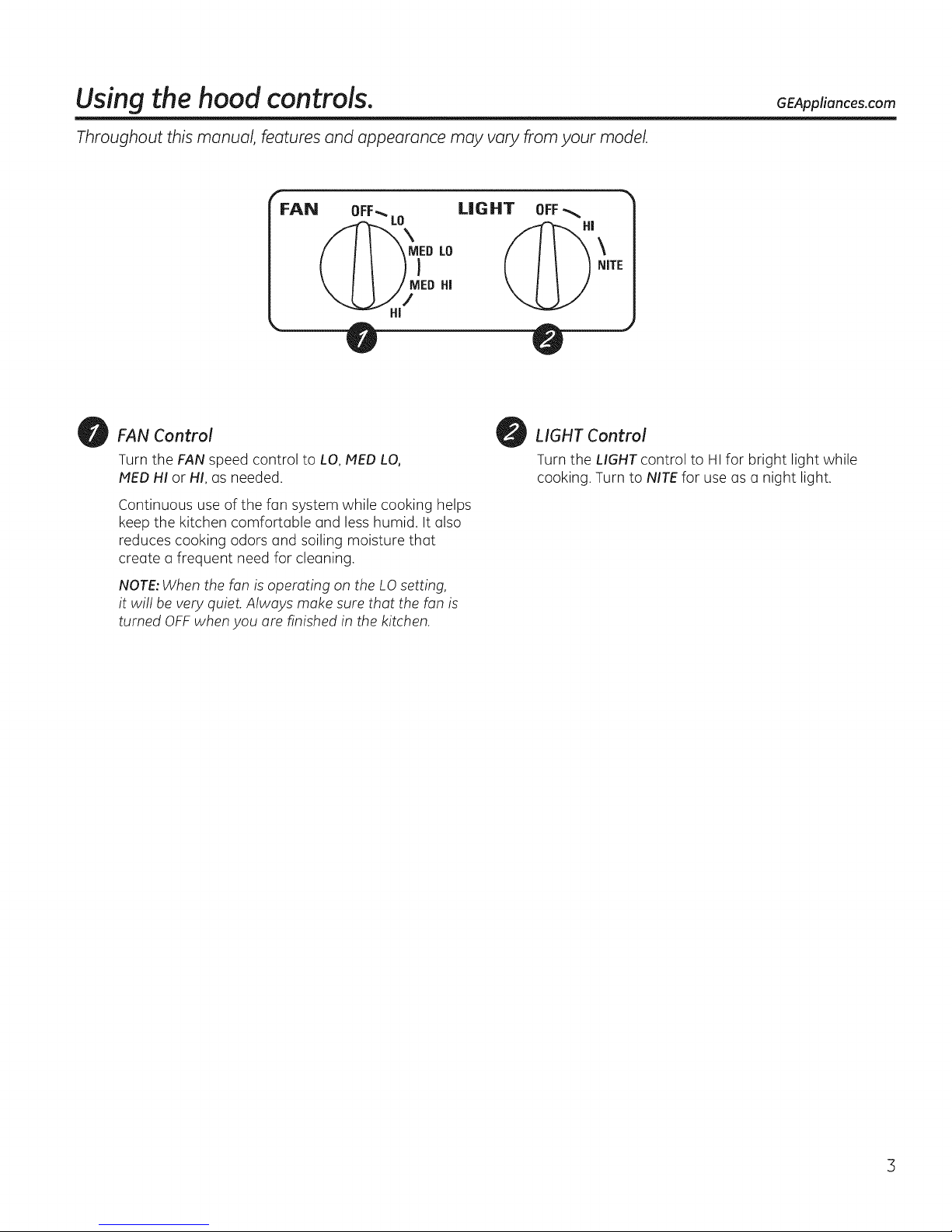
FAN Control
Turn the FAN speed control to LO, MED LO,
MED HI or HI, as needed.
Continuous use of the fan system while cooking helps
keep the kitchen comfortable and less humid, It also
reduces cooking odors and soiling moisture that
create a frequent need for cleaning.
NOTE: When the fan is operating on the LO setting,
it will be very quiet. Always make sure that the fan is
turned OFFwhen you are finished in the kitchen.
OFF
HI
\
NITE
LIGHT Control
Turn the LIGHT control to HI for bright light while
cooking. Turn to NITE for use as a night light.
Care and cleaning of the vent hood,
Be sure electrical power is off and all surfaces are cool before cleaning or servicing any part of the vent hood.
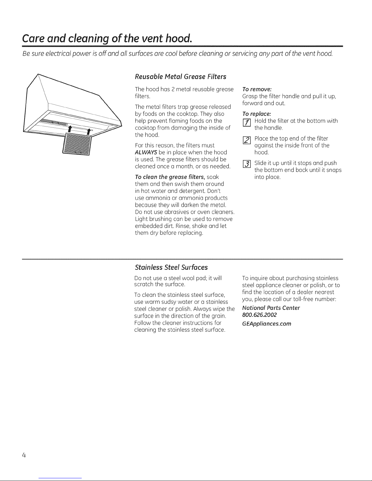
Reusable Metal Grease Filters
The hood has 2 metal reusable grease
filters.
The metal filters trap grease released
by foods on the cooktop. They also
help prevent flaming foods on the
cooktop from damaging the inside of
the hood.
For this reason, the filters must
ALWAVSbe in place when the hood
is used. The grease filters should be
cleaned once a month, or as needed.
To clean the grease filters, soak
them and then swish them around
in hot water and detergent. Don't
use ammonia or ammonia products
because they will darken the metal.
Do not use abrasives or oven cleaners.
Light brushing can be used to remove
embedded dirt. Rinse, shake and let
them dry before replacing.
To remove:
Grasp the filter handle and pull it up,
forward and out.
To replace:
m Hold the filter at the bottom with
the handle.
[] Placethe top end of the filter
against the inside front of the
hood.
r_ Slideit up until it stops and push
the bottom end back until it snaps
into place.
Stainless Steel Surfaces
Do not use a steel wool pad; it will
scratch the surface.
To clean the stainless steel surface,
use warm sudsy water or a stainless
steel cleaner or polish. Always wipe the
surface in the direction of the grain.
Follow the cleaner instructions for
cleaning the stainless steel surface.
To inquire about purchasing stainless
steel appliance cleaner or polish, or to
find the location of a dealer nearest
you, please call our toll-free number:
National Parts Center
800.626.2002
GEAppliances.com
GEAppliances.com
Besureelectricalpower isoff and allsurfacesarecoolbeforecleaningor-servicinganypart of the vent hood.
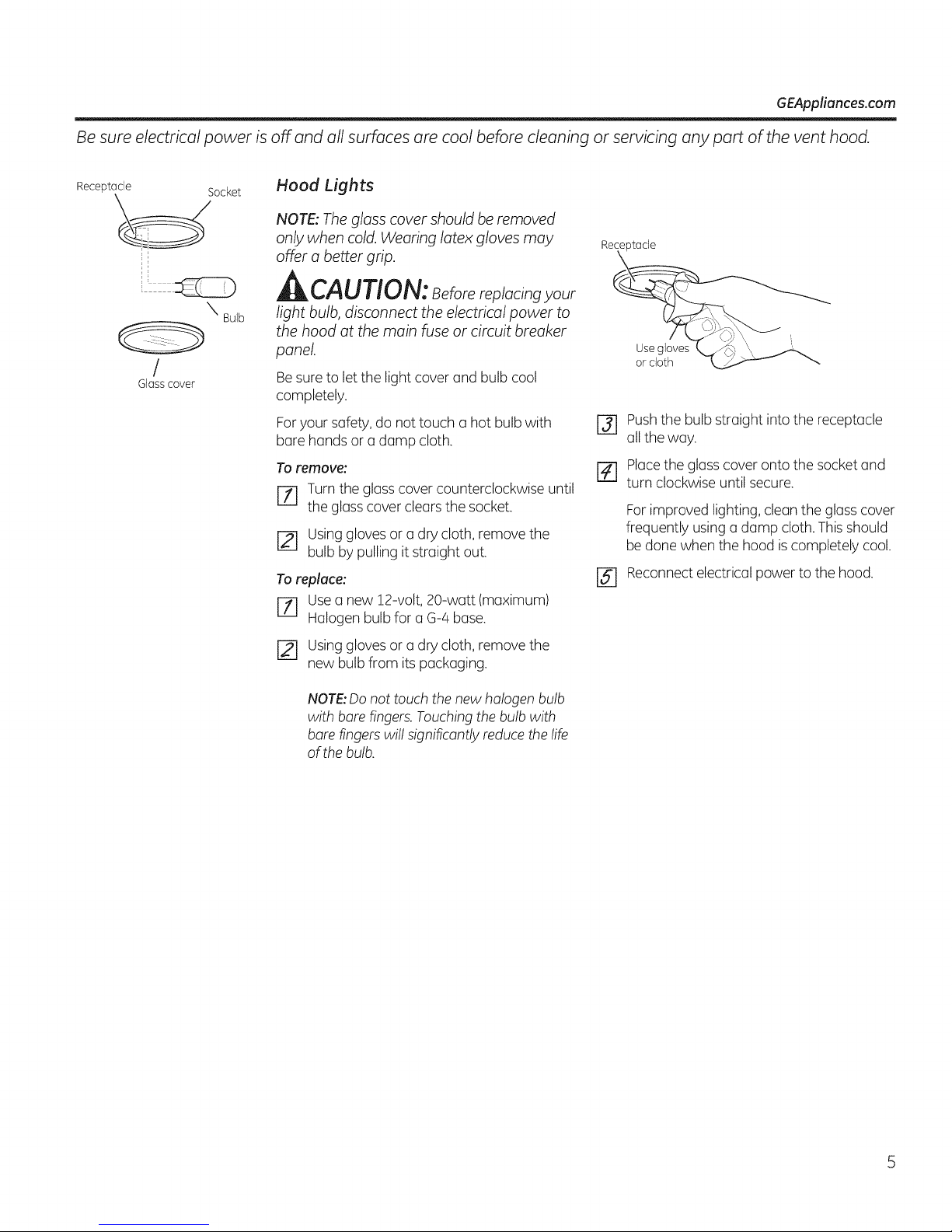
Receptacle Socket
X Bulb
/
Glasscover
Hood Lights
NOTE: Thegloss cover should be removed
only when cold. Wearing latex gloves may
offer o better grip.
CAUTION: eforereplacingyour
light bulb, disconnect the electrical power to
the hood at the main fuse or circuit breaker
panel.
Besureto let the light cover and bulb cool
completely.
Foryour safety, do not touch a hot bulb with
bare hands or a damp cloth.
Toremove:
r_ Turn the glass cover counterclockwise until
the glasscover clears the socket.
r_ using gloves or a dry cloth, remove the
bulb by pulling it straight out.
Toreplace:
[Z] Usea new 12-volt, 20-watt (maximum)
Halogen bulb for a G-4 base.
Re_ade
or cloth __ "_-
r_ Pushthe bulb straight into the receptacle
all the way.
r_ Placethe glass cover onto the socket and
turn clockwise until secure.
Forimproved lighting, clean the glass cover
frequently using a damp cloth. This should
be done when the hood is completely cool.
rs] Reconnectelectrical power to the hood.
[] Usinggloves or a dry cloth, remove the
new bulb from its packaging.
NOTE:Do not touch the new halogen bulb
with bare fingers. Touching the bulb with
bare fingers will significantly reduce the life
of the bulb.
I stall ti
Instructi
ange Hoods
i Questions? Cull 800.GE.CARES (800.432.2737) or visit our Website ot: www.GEAppliunces.com. i
BEFORE YOU BEGIN
Read these Instrucitons completely and carfully.
"IMPORTANT- Soretheseinstructions
for local inspector's use.
" IMPORTANT- Observe oligoverning
codes ond ordinances.
, Note to Installer - Be sure to leove these
instructions with the Consumer.
, Note to Consumer - Keep these instrucitons
for future reference.
Skill Level - Instollotion of this vent hood
requires basic mechonicol and electrical skills.
Completion time - 1to 3 hours.
• Proper installation is the responsibility of the
instoller.
Product foilure clue to improper installation is
not covered under the Warranty.
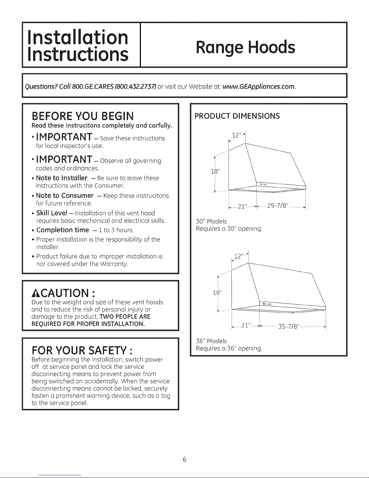
30" Models
Requires o 30" opening.
ACAUTION ."
Due to the weight ond size of these vent hoods
ond to reduce the risk of personol injury or
domoge to the product, TWO PEOPLE ARE
REQUIRED FOR PROPER INSTALLATION.
FOR YOUR SAFETY:
Before beginning the instollotion, switch power
off ot service ponel ond lock the service
disconnecting means to prevent power from
being switched on occidentolly. When the service
disconnecting meons connot be locked, securely
fosten o prominent worning device, such os o tog
to the service ponel.
18"
35-7/8" ...................
36" Models
Requireso 36" opening.
Installation Instructions
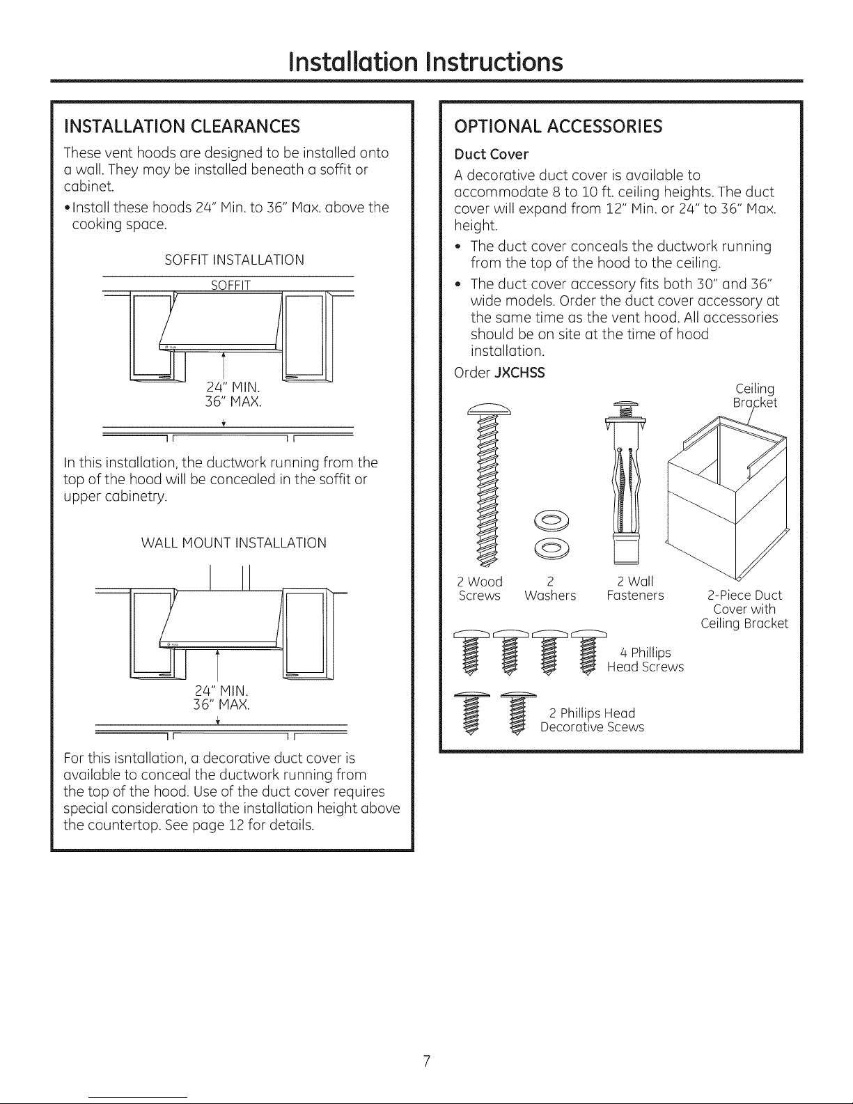
INSTALLATION CLEARANCES
These vent hoods are designed to be installed onto
a wall. They may be installed beneath a soffit or
cabinet.
,Install these hoods 24" Hin. to 36" Max. above the
cooking space.
SOFFIT INSTALLATION
SOFFIT
In this installation, the ductwork running from the
top of the hood will be concealed in the soffit or
upper cabinetry.
OPTIONAL ACCESSORIES
Duct Cover
A decorative duct cover is available to
accommodate 8 to 10 ft. ceiling heights. The duct
cover will expand from 12" Min. or 24" to 36" Max.
height.
, The duct cover conceals the ductwork running
from the top of the hood to the ceiling.
, The duct cover accessory fits both 30" and 36"
wide models. Order the duct cover accessory at
the same time as the vent hood. All accessories
should be on site at the time of hood
installation.
Order J×CHSS
Ceiling
Bra
WALL MOUNT INSTALLATION
24" MIN.
36" MAX.
11 I_
For this isntallation, a decorative duct cover is
available to conceal the ductwork running from
the top of the hood. Use of the duct cover requires
special consideration to the installation height above
the countertop. See page 12 for details.
2 Wood
Screws2Washers
_;_ _;_ _ _;_ 4 Phillips
_ 2 Phillips Head
Decorative Scews
2 Wall
Fasteners
Head Screws
2-Piece Duct
Cover with
Ceiling Bracket
Installation Instructions
ADVANCE PLANNING
Ductwork Planning
Thishoodmay be ventedverticallythrough uppercabinets,
soffit or ceiling.Aduct transitionpiece issuppliedfor vertical
exhaust.Uselocallysuppliedelbowsto vent horizontally
throughthe rearwall.Seepage 13.
Determinethe exactlocationof theventhood.
Planthe route forventing exhaustto the outdoors.
Usetheshortestand straightest duct routepossible.FFor
satisfactoryperformance,duct run should notexceed100
equivalentlengthfor anyductconfigurations.
Usemetal ductwork only.
Atransition piecefor 7" roundduct issupplied.Use7"round
duct oryou may use3-1/4" x 12" rectangular.
Installa wall capor roofcap with damperat the exterior
opening.Orderthe wall or roof cap and any transition
neededin advance.
Kit- J×DW1
Orderkit J×DW1ifyour installationrequireshorizontalducting
from the top ofthe hood throughthe backwall and:
• Youhavean 8ft. ceilingand needto use a JXCHSeries
ChimneyCover,or
• Youhavea 12"cabinet or 12" soffitthat the hoodisto be
mountedbeneath.
Thiskitprovidesa duct transitionfrom 7" round to 3-1/4"x 10"
rectangularfor through-the-wall venting.
Wall Framing for Adequate Support
• Thisvent hood isheaw. Adequate structurealsupport must
beprovided.Thehood must besecuredto verticalstuds in
thewall. Seepage 14.
• Westrongly recommendthat the vent hoodwith duct cover
beon sitebeforefinal framing and wallfinishing.Thiswill
alsohelpto accuratelylocatethe ductwork and electrical
service.
DECORATIVE DUCT COVERS
A decorativeductcoveris availabletofit bothmodelwidths.
Theduct coverconcealsthe ductwork runningfrom the top of
the hoodto theceilingorsoffit_Theduct coverwillfit 8 ft. to !0
ft.ceilingheights.Seepage!2 for details.
POWER SUPPLY
IMPORTANT-(Pleaseread carefully)
AWARNING:
FORPERSONALSAFETY,THISAPPLIANCEMUSTBEPROPERLY
GROUNDED.
Removehousefuse or opencircuitbreakerbeforebeginning
installation.
Donot useanextensioncordoradapterplugwith this
appliance.FollowNationalelectricalcodesor prevailinglocal
codesand ordinances.
EJectricaJ suppJy
Thisvent hoodmust besuppliedwith 120V,60Hz,and
connectedto an individual,properlygroundedbranchcircuit,
and protectedby a 15or 20amp circuitbreakeror time delay
fuse.
Wiringmust be 2wirewith ground.
Ifthe electricalsupplydoesnot meetthe above
requirements,calla licensedelectricianbeforeproceeding.
Routehousewiring ascloseto the installatonlocationas
possibleintheceiling,soffitorwall.Seepage !3 for details.
Connectthe wiringto the housewiringin accordancewith
localcodes.
Grounding instructions
Thegroundingconductor must beconnectedto a ground
metal,permanentwiring system,or an equipment-grounding
terminal or leadon the hood.
A WARNiNG:Theimproperconnectionofthe
equipment-groundingconductorcanresultinariskofelectricshock.
Checkwithaqualifiedelectricianorservicerepresentativeifyouare
indoubtwhethertheapplianceisproperlygrounded..
Installation Instructions
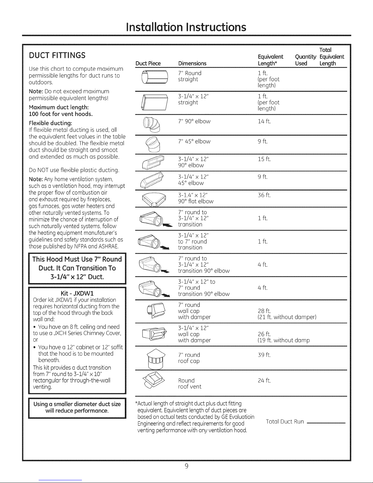
DUCT FITTINGS
Usethis chart to compute maximum
permissible lengths for duct runs to
outdoors.
Note: Do not exceed maximum
permissible equivalent lengths!
Maximum duct length:
100 foot for vent hoods.
Flexible ducting:
If flexible metal ducting is used, all
the equivalent feet values in the table
should be doubled. The flexible metal
duct should be straight and smoot
and extended as much as possible.
Do NOTuse flexible plastic ducting.
Note: Any homeventilationsystem,
such asa ventilation hood,mayinterrupt
the proper flow of combustion air
and exhaustrequired by fireplaces,
gasfurnaces,gas water heatersand
other naturally vented systems.To
minimizethe chanceof interruption of
such naturallyvented systems,follow
the heating equipment manufaturer's
guidelinesand safety standards such as
those publishedby NFPAand ASHRAE.
Equivalent
Duct Piece Dimensions Length*
7" Round 1 ft.
straight (per foot
length)
straight (per foot
3-Z/Z4"x 12" 1 ft.
7" 90° elbow lz4ft.
7" 45° elbow 9 ft.
3-!/z4" x 12" 15 ft.90° elbow
3-1/z4"x 12" 9 ft.
/45°elbow
90° flat elbow
3-1.4" x 12" 36 ft.
__ 7" round to
__j_ 3-!/Z4" x 12"
3-1/Z4"x 12" ! ft.
transition
to 7" round ! ft.
transition
length)
Total
Quantity Equivalent
Used Length
This Hood Must Use 7" Round
Duct. It Can Transition To
3-1/4" x 12" Duct.
Kit - J×DW1
Order kit JXDW1if your installation
requires horizontal ducting from the
top of the hood through the back
wall and:
. Youhave an 8 ft. ceilingand need
to use a JXCHSeriesChimneyCover,
or
Youhave a 12"cabinetor 12" soffit
that the hood is to be mounted
beneath.
Thiskit providesa duct transition
from 7" round to 3-1/4" x 10"
rectangular forthrough-the-wall
venting.
will reduce performance.
Using a smaller diameter duct size
7" round to
3-1/z4"x 12" z4ft.
transition 90° elbow
3-!/z4" x 12" to
7" round z4ft.
transition 90° elbow
wall cap 28 ft.
7" round
with damper (21 ft. without damper)
wall cap 26 ft.
3-1/z4" x 12"
with damper (19 ft. without damp
roof cap
7" round 39 ft.
Round 2z4ft.
roof vent
*Actuallength ofstraight duct plusductfitting
equivalent.Equivalentlengthof duct piecesare
basedon actualtests conducted byGEEvaluatioin
Engineeringand reflectrequirementsfor good
venting performancewith anyventilation hood.
Total Duct Run
9
Installation Instructions
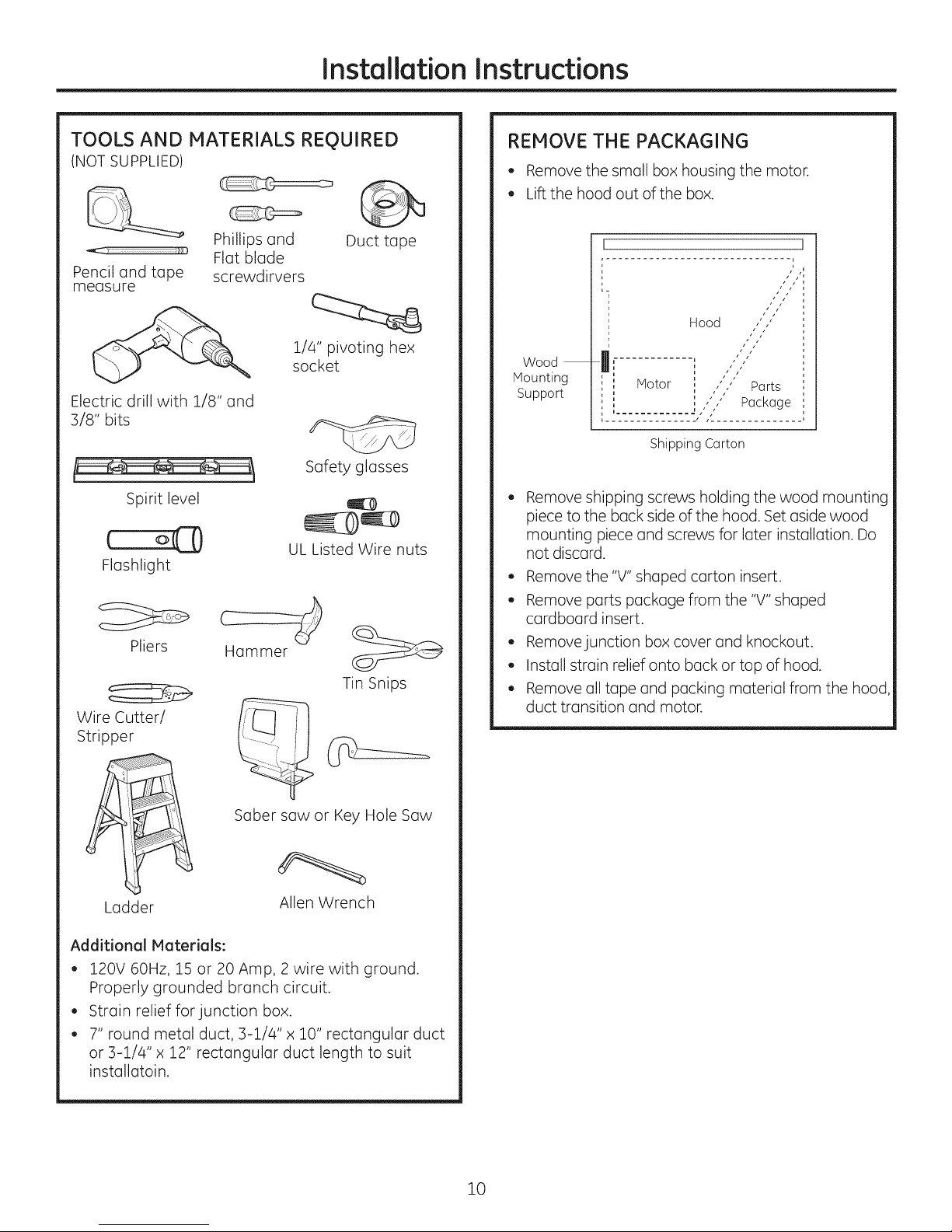
TOOLS AND MATERIALS REQUIRED
(NOT SUPPLIED)
Phillips and
Flat blade
Pencil and tape
measure
screwdirvers
Electric drill with 1/8" and
3/8" bits
Spirit level
€ o@
Flashlight
Pliers
Wire Cutter/
Stripper
Hammer
1/4" pivoting hex
socket
UL Listed Wire nuts
Duct tape
Safety glasses
Tin Snips
REMOVE THE PACKAGING
, Remove the small box housing the motor.
, Lift the hood out of the box.
Hood ""
, yiiS'
Wood
Mounting
Support
Notor , ,' ," Parts
u............ 2 ," t
, ............... , J_ .............. ,
Remove shipping screws holding the wood mounting
piece to the back side of the hood. Set aside wood
mounting piece and screws for later installation. Do
not discard.
, Remove the "V" shaped carton insert.
, Remove parts package from the "V" shaped
cardboard insert.
, Removejunction box cover and knockout.
, Install strain relief onto back or top of hood.
, Remove all tape and packing material from the hood
duct transition and motor.
i
u s t /
u s
i s /
I ,',,, Package
Shipping Carton
Saber saw or Key Hole Saw
Ladder
Allen Wrench
Additional Materials:
, 120V 60Hz, 15 or 20 Amp, 2 wire with ground.
Properly grounded branch circuit.
, Strain relief far junction box.
, 7" round metal duct, 3-1/4" x 10" rectangular duct
or 3-1/4" x 12" rectangular duct length to suit
instullutoin.
10
Installation Instructions
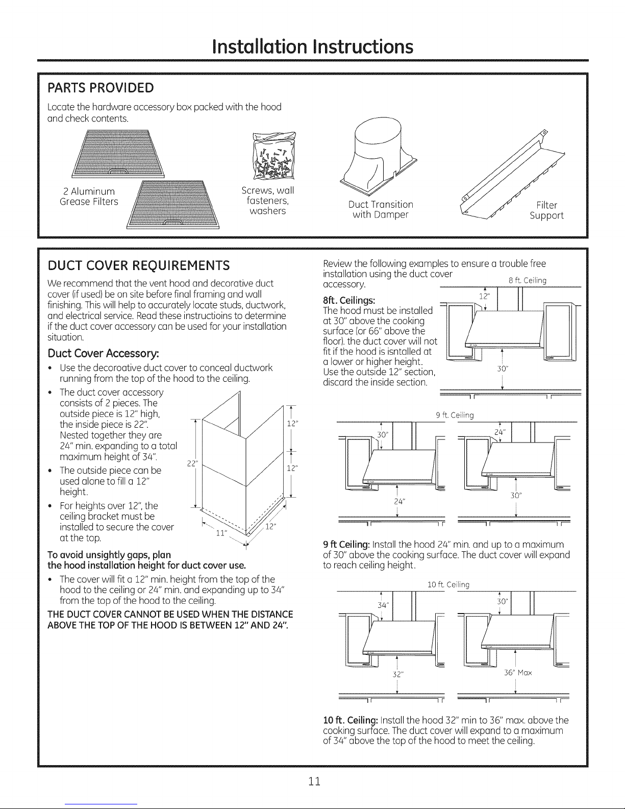
PARTS PROVIDED
Locatethe hardware accessory box packed with the hood
and checkcontents.
2 Aluminum
Grease Filters
Screws, wall
fasteners, Duct Transition
washers with Damper
DUCT COVER REQUIREMENTS
We recommend that the vent hood and decorative duct
cover (ifused)be on site before final framing and wall
finishing.Thiswill helpto accurately locate studs,ductwork,
and electrical service.Readthese instructioins to determine
ifthe duct cover accessory can be usedfor your installation
situation.
Duct Cover Accessory:
. Usethe decoroative duct cover to conceal ductwork
running from the top of the hood to the ceiling.
. Theduct cover accessory
consists of 2 pieces.The
outside piece is12" high,
the insidepiece is22" 12"
Nestedtogether they are I
24"min.expanding to a total
maximum height of 34". 22"
. Theoutside piececan be _ 12"
usedalone to fill a 12"
height.
. For heights over 12",the
ceiling bracket must be <"_
installedto secure the cover •12"
at the top. 11"
To avoid unsightly gaps, plan
the hood installation height for duct cover use.
. Thecover will fit a 12" min. height from the top of the
hood to the ceiling or 24" min. and expanding up to 34"
from the top of the hood to the ceiling.
THEDUCTCOVERCANNOTBEUSEDWHENTHEDISTANCE
ABOVETHETOPOF THEHOOD ISBETWEEN12"AND 24".
Filter
Support
Reviewthe following examples to ensure a trouble free
installation usingthe duct cover 8 ft. Ceiling
accessory.
A
8ft. Ceilings: ::z_r-.12"
Thehood must be installed II I1__€
at 30" above the cooking
surface (or 66" above the
floor),the duct cover will not
fit ifthe hood isisntalled at t
a lower or higher height.
Usethe outside 12" section, so"
discard the insidesection.
--11 ] F--
9 ft. Ceiling
t so"
24"
--! I I r --I I t I_
9 ft Ceiling: Installthe hood 24" min. and up to a maximum
of 30" above the cooking surface.The duct cover will expand
to reachceiling height.
36" Max
1F --11 iF--
10ft. Ceiling: Installthe hood 32" min to 36" max.above the
cooking surface.The duct cover will expand to a maximum
of 34" above the top of the hood to meet the ceiling.
11
Installation Instructions
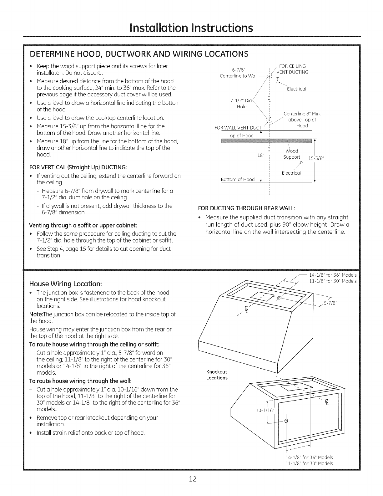
DETERMINE HOOD, DUCTWORK AND WIRING LOCATIONS
Keepthe wood support pieceand its screws for later
installaton. Do not discard.
, Measuredesired distance from the bottom of the hood
to the cooking surface, 24" min.to 56" max. Referto the
previous page ifthe accessory duct cover will be used.
, Usea levelto draw a horizontal line indicating the bottom
ofthe hood.
Usea levelto draw the cooktop centerline location.
. Measure 15-3/8" up from the horizontal Ilinefor the
bottom of the hood. Draw another horizontal line.
Measure 18"upfrom the line for the bottom of the hood,
draw another horizontal line to indicate the top of the
hood.
FOR VERTICAL (Straight Up) DUCTING:
If venting out the ceiling, extend the centerline forward on
the ceiling.
- Measure 6-7/8" from drywall to mark centerline for a
7-1/2" dia. duct hole on the ceiling.
- If drywall is not present, add drywall thickness to the
6-7/8" dimension.
Venting through a soffit or upper cabinet:
. Followthe same procedure for ceilingducting to cut the
7-1/2" dia. hole through the top of the cabinet orsoffit.
. SeeStep 4, page 15for details to cut opening for duct
transition.
, / FOR CEILING
6-7/8" _/ VENT DUCTING
Centedine to Wall /.[. _,
' ""Electrical
7-1/2" Dia.<
Hole \,
'xX Centerline 8" Min.
X_ h jJ
FOR WALL VENT DUCT '_'_"'/z
Top of Hood I
I
Bottom of Hood
€
18" i
, Support
i
i
i
i
i
', Electrical
above
Hood
Top
of
15-3/8"
FOR DUCTING THROUGH REAR WALL:
Measure the supplied duct transition with any straight
run length of duct used, plus 90" elbow height. Draw a
horizontal line on the wall intersecting the centerline.
House Wiring Locution:
. Thejunction box isfastenend to the back of the hood
on the right side.Seeillustrations for hood knockout
locations.
Note:Thejunction box can be relocated to the insidetop of
the hood.
Housewiring may enter thejunction boxfrom the rear or
the top of the hood at the right side.
To route house wiring through the ceiling or soffit:
- Cut a hole approximately r' dia.,5-7/8" forward on
the ceiling;11-!/8" to the right of the centerline for 30"
models or 14-1/8" to the right of the centerline for 36"
models.
To route house wiring through the wall:
- Cut a hole approximately r' dia. 10-1/16" down from the
top of the hood, 1!-!/8" to the right of the centerline for
30"modelsor 14-1/8" to the right of the centerline for 36"
models..
. Removetop or rear knockout depending on your
installation.
. Installstrain reliefonto back or top of hood.
Knockout
Locations
.--- 14-1/8" for 36" Models
.4_..../ 11-1/8" for 30" Models
/
14-1/8" for 36" Models
11-1/8" for 30" Models
12
Installation Instructions
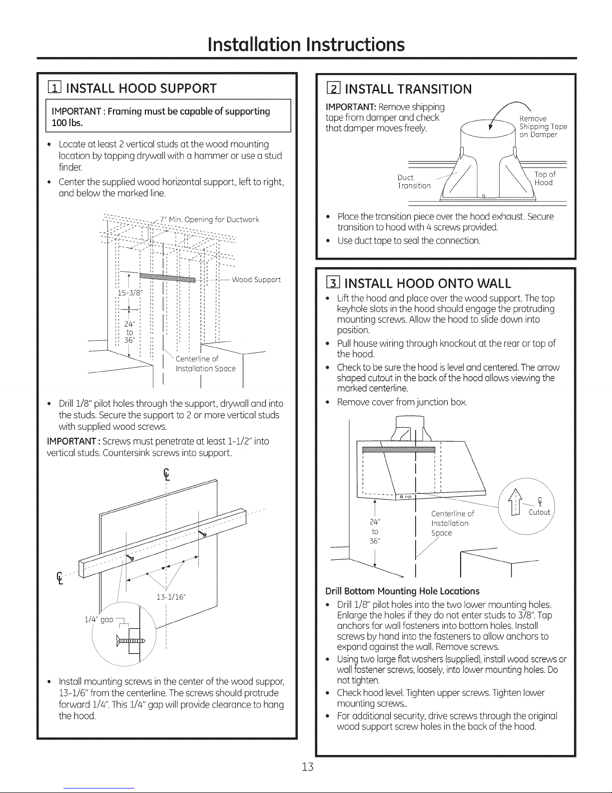
Fi] INSTALL HOOD SUPPORT
IMPORTANT:Framing must be capable of supporting
100 Ibs.
e
Locate at least 2 vertical studsat the wood mounting
location by tapping drywall with a hammer or usea stud
finder.
Centerthe supplied wood horizontal support, left to right,
and below the marked line.
Hin. Opening for Ductwork
IL_
Wood Support
Centedine of F_
Installation Space
I
. Drill 1/8" pilot holesthrough the support, drywall and into
the studs. Securethe support to 2 or more vertical studs
with supplied wood screws.
IMPORTANT:Screwsmust penetrate at least !-!/2" into
vertical studs.Countersink screws into support.
/
D INSTALL TRANSITION
IMPORTANT:Removeshipping
tape from damper and check
that damper movesfreely.
Duct Top of
Transition Hood
Remove
Shipping Tape
on Damper
. Placethe transition pieceoverthe hood exhaust.Secure
transitionto hood with 4 screws provided.
. Useduct tape to sealthe connection.
[] INSTALL HOOD ONTO WALL
. Liftthe hood and placeover the wood support. The top
keyhole slotsin the hood should engage the protruding
mounting screws.Allowthe hood to slidedown into
position.
. Pullhouse wiring through knockout at the rear or top of
the hood.
. Checkto besurethe hoodis leveland centered.Thearrow
shapedcutout inthe backof the hood allowsviewingthe
marked centerline.
. Remove cover from junction box.
l/a/',,gap
/
£
Installmounting screws in the center of the wood suppor,
13-1/6" from the centerline.The screwsshould protrude
forward 1/4".This 1/4" gap will provide clearance to hung
the hood.
°
°
24"
to
36"
Centerlin
Installation \
S/pace
L
q
Drill Bottom Mounting Hole Locutions
. Drill 1/8" pilot holesinto the two lower mounting holes.
Enlargethe holes iftheydo not enter studs to 3/8" Tap
anchors for wall fasteners into bottom holes.Install
screws by hand intothe fasteners to allow anchors to
expand against the wall. Removescrews.
. Usingtwo largeflat washers(supplied),installwood screwsor
wallfastenerscrews,loosely,intolowermounting holes.Do
nottighten.
. Checkhood level.Tighten upper screws.Tightenlower
mounting screws..
. For additional security, drive screwsthrough the original
wood support screwholes inthe buck of the hood.
13

Installation Instructions
F4-1Alternate Mounting Method
INSTALL HOOD TO SOFFIT OR
BENEATH CABINETS
SKIPTHIS STEPIF USING WALL MOUNTING METHOD
IMPORTANT: Soffit framing must be capable of
supporting 1OOibm
When necessarythe hood may be installed sothat it is
supported by the soffit.
, Thesoffit should be constructed with 2x4's,
, Determine the installation location,.
, Continuethe centerline forward on the bottom of the
cabinet or soffit.
A
IMPORTANT: For additional support and to minimize
vibration during operation, we strongly recommend
that the hood also be secured to the buck wall with wall
fastners.
30" Models
2-9/16"
7-1/16"
_,_14-i/2"
2-3/8" I
,J_ 14-1/2"
I
I
] ......... ]
€,
¢ !8-7/16
......... 4J......... I _ul
I
29-7/8"
Top View, Front Side
36" Models
2-9/16"
7-1/16"
17-1/2 "__ 17-1/2"
I
1 ,
2-3/8" _. 10_3/4._
', ¢ 8-7/16"
', i
' 2
i ........ "4 ......... J
Vue de dessus, partie avant
I
35-7/8"
2"
2"
"A .... B"
Centerline to Opening for
Center of Stud Ductwork
30" Models 14-1/2" 10-3/4" W × 8-7/16 D
36" Nideks 17-1/2" 10-3/4" W × 8-7/16 D
Mounting screws must be secured to 2 x4 studs (Dim."A")
at locations shown in the above chart.
Allow minimum opening (Dim. "B") to accommodate
the duct transition in the soffit
Rear Wall
I
1 ,
2-3/8" [,,_ , I
Cut a !0-3/4" x 8-7/16" hole through bottom of soffit or
cabinet for duct transition msshown.
5-3/8" _ 5-3/8" _
11
, ¢ 8-7/16"
I i
L ........ 4 ......... J
I
Top View, Front Side
A
Drillfour 1/8" pilot holes in locations show.
If mounting to the underside of a cabinet with a
recessed bottom, install shims to fill the gap.
I
l
',Shlmms if
114"Gap
Engage KeyholeSlots
and Push Back atWall _'
, Drive mounting screws int the studs until they
protrude 1/4".This 1/4" gap will provide clearance to
engage the keyhole slots in the top of the hood.
, Lift hood onto mounting screws, slide back against
the rear wall.
, Pull house wiring through the knockout at the rear or
top of the hood.
, Tighten mounting screws.
Bottom is
Recessed.
Add
14
 Loading...