

GE Appliances GEH5ODNSRSA, Appliances GEH5ODXSRGA, GEH50DNSRSA, GEH50DXSRGA Owner's Manual And Installation Instructions
Page 1
C3
GEAppliances.com
Safety Information ........... 2,s
Operating Instructions ..... 4-11
Care and Cleaning ......... 12,13
Installation Instructions...14-1s
GEH5ODNSRSA
GEH5ODXSRGA
rY
m
Iii
U3
U
U
Troubleshooting Tips ...... 19,20
Consumer Support ......... 22,68
Chauffe-eau
r_sidentiel hgbride _lectrique
La section franqaise commence a la page 23
Calentadores
de agua
residenciales el_ctricos hibridos
La secci6n en espa_ol empieza en la p_gina 45
Write the model and serial
numbers here:
Model #
Serial #
Youcan find them on the rating label
on the front side of your water heater.
49-50254 10-09 JR
Page 2
IMPORTANTSAFETYINFORMATION.
I
m.
I
"(3
L_
READALL INSTRUCTIONSBEFOREUSING.
A WARNING!
For your safety, the information in this manual must be followed to minimize the risk of fire or explosion,electric shock, orto
prevent property damage, personal injury, or lossof life.
Be sureto read and understand the entire Owner's Manual before attempting to install or operate this water heater. It may
save you time and cost. Pay particular attention to the Safety Instructions. Failureto follow thesewarnings could result in
serious bodily injury or death. Should you have problems understanding the instructions in this manual, or have any questions,
STOPand get help from a qualified service technician or the local electric utility.
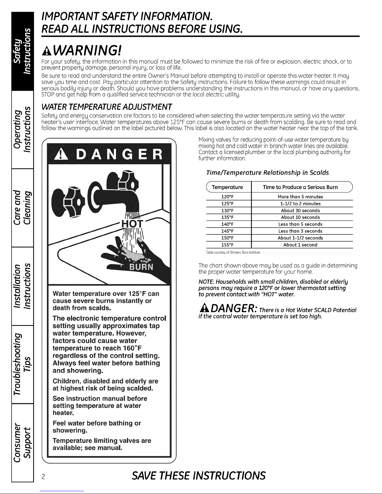
WATER TEMPERATURE ADJUSTMENT
Safety and energy conservation arefactors to be considered when selecting the water temperature setting via the water
heater's user interface. Water temperatures above 125°Fcan cause severe burns or death from scalding. Besure to read and
follow the warnings outlined on the label pictured below.This label isalso located on the water heater near the top of the tank.
Mixingvalvesfor reducing point-of-use water temperature by
mixing hot and cold water in branch water linesare available.
Contact a licensedplumberor the local plumbingauthority for
further information.
Time/Temperature Relationship in Scalds
HOT
120°F
125°F
130°F
135°F
140°F
145°F
150°F
155°F
TablecourtesyofShrinersBUm Institute
More thon 5 minutes
1-1/2 to 2 minutes
About 30 seconds
About 10 seconds
Less thon 5 seconds
Less thon 3 seconds
About 1-1/2 seconds
About i second
0
t_
0
0
a_
..(3
5...
E
0
t_
Water temperature over 125°F can
cause severe burns instantly or
death from scalds.
The electronic temperature control
setting usually approximates tap
water temperature. However,
factors could cause water
temperature to reach 180°F
regardless of the control setting.
Always feel water before bathing
and showering.
Children, disabled and elderly are
at highest risk of being scalded.
See instruction manual before
setting temperature at water
heater.
Feel water before bathing or
showering.
Temperature limiting valves are
available; see manual.
Thechart shown above may be used as a guide in determining
the proper water temperature for your home.
NOTE:Households with small children, disabled or elderlg
persons mag require a 120°For lower thermostat setting
to prevent contact with "HOT"water.
A DANGER: ThereisaHotWaterSCALDPotential
if thecontrol water temperature is set too high.
2 SAVE THESE INSTRUCTIONS
Page 3
GEAppliances.com
WARNING!
Gasoline, as well as other flammable materials
and liquids (adhesives, solvents, etc.),and the
vapors theg produce are extremelg dangerous.
DONOThandle, use or store gasoline or other
flammable or combustible materials angwhere
near or in the vicinitg of a water heater. The arc
drawn in the water heater controls can ignite
these vapors. Failure to do so can result in
propertg damage, bodilg injurg or death.
_, FOR INSTALLATIONS
IN THE STATEOF CALIFORNIA
California Law requires that residential water
heaters must be braced, anchored or strapped
to resist falling or horizontal displacement due
to earthquake motions. For residential water
heaters up to 52 gallon capacity, a brochure with
generic earthquake bracing instructions can be
obtained from: Office of the State Architect, 400 P
Street, Sacramento, CA 95814 or gou mag call
916.324.5315 or ask a water heater dealer.
However, applicable local codes shall govern
installation. For residential water heaters of a
capacitg greater than 52 gallons, consult the local
building jurisdiction for acceptable bracing
procedures.
California Proposition 65 Warning: This product
contains chemicals known to the State of
California to cause cancer, birth defects or other
reproductive harm.
READAND FOLLOWTHISSAFETYINFORMATIONCAREFULLY.
SAVE THESE INSTRUCTIONS
Page 4
Operating the water heater.
A,_ WARNIN G: Hydrogen gas can beproduced in a hot water system served by this water heater that has not been
usedfor a long period of time (generallytwo weeks or more).HYDROGENGASISEXTREMELYFLAP1P1ABLE!!Todissipatesuch gas
and to reduce riskof injury, it isrecommended that the hot water faucet be opened for several minutes at the kitchen sink
before usingany electrical appliance connected to the hot water system. Ifhydrogen ispresent,there will be an unusual sound
such as air escapingthrough the pipeasthe water beginsto flow. Do not smoke or usean open flame near the faucet at the
time it isopen.
Safety Precautions
WARNING:
If the water heater has been
subjected to flood, fire, or phgsical
damage, turn off power and water
to the water heater.
Do not operate the water heater
again until it has been thoroughly
checked by qualified service
personnel.
A. Doturn off power to water heater if
it has beensubjectedto overheating,
fire, flood or physical damage.
B.Do Not turn on water heater unless
it isfilled with water.
C.D.Do Not turn on water heater ifcold
water supply shut-off valve is closed.
Do Not store or usegasoline or other
flammable vapors and liquids,such as
adhesivesor paint thinner,in the vicinity
of this or any other appliance. Ifsuch
flammables must be used,open doors
and windows for ventilation.
Safetg Controls
Thewater heateris equippedwith two
temperature-limitingcontrols (TCOs)that
are located abovethe heating elementin
contact with thetank surface.Iffor any
reasonthe water temperaturebecomes
excessivelyhigh,the temperature-limiting
control (TCO)breaksthe power circuitto
the heatingelement. Oncethe control
opens,itmust beresetmanually.Resetting
of thetemperature limiting controlsshould
bedone by a qualifiedservicetechnician.
CAUTION: Thecause
of the high temperature condition must
be investigated bga qualified service
technician and corrective action must
be taken beforeplacing the water heater
in service again.
NOTE:Flammable vapors mag be drawn
bg air currents from surrounding areas to
the water heater.
E.Ifthere isany difficulty inunderstanding
or following the Operating Instructions
or the Careand Cleaning section, it is
recommended that a qualified person
or serviceman perform the work.
To reset the temperature-limiting
control:
1.Turn off the power to the water
heater.
2.
Remove the jacket access ponel(s)
and insulation.
The thermostat protective cover
should not be removed.
3. Press the red RESETbutton.
4. Replace the insulation and jocket
occess panel(s) before turning on
the power to the water heater.
/4
Page 5
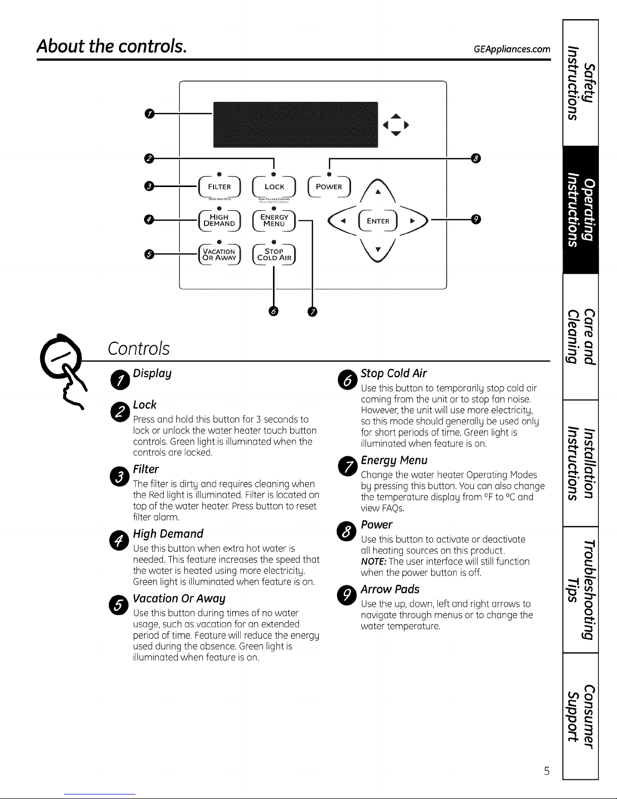
About the controls. GEApp,ionces.com
0
@
0 ® •
0
O
G
. ._.AND_ __MENU_J-- NT
_ACAT,ON_ _--STOP--_
" "
k93A_Z) LC3,oA,_)
Controls
Display
Lock
Pressond hold this button for 3 seconds to
lock or unlockthe woter heoter touch button
controls. Green light is illuminoted when the
controls ore locked.
o Filter
The filter is dirtg ond requires cleoning when
the Redlight is illuminoted. Filter is Iocoted on
top of the woter heoter. Pressbutton to reset
filter olorm.
High Demand
@
Usethis button when extro hot water is
needed.This feoture increoses the speed thot
the woter is heoted using more electricitg.
Green light isilluminoted when feoture ison.
Vacation Or Awag
0
Usethis button during times of no water
usoge, such osvocotion for on extended
period of time. Feoture will reduce the energg
used during the obsence. Green light is
illuminoted when feoture is on.
I I
t-
A
,q j,
Y
0
Stop Cold Air
0
Usethis button to tempororily stop cold air
coming from the unit orto stop fon noise.
However,the unit will usemore electricitg,
sothis mode should generollg be used onlg
for short periods of time. Green light is
illuminoted when feoture ison.
Energg Menu
@
Chonge the woter heoter Operoting Modes
bg pressing this button. You con olso chonge
the temperoture displog from °Fto °Cond
view FAQs.
Power
O
Usethis button to activate or deactivate
all heating sources on this product.
NOTE:The user interface will still function
when the power button is off.
Arrow Pads
@
Usethe up, down, left and right arrows to
navigate through menus or to change the
water temperature.
Page 6
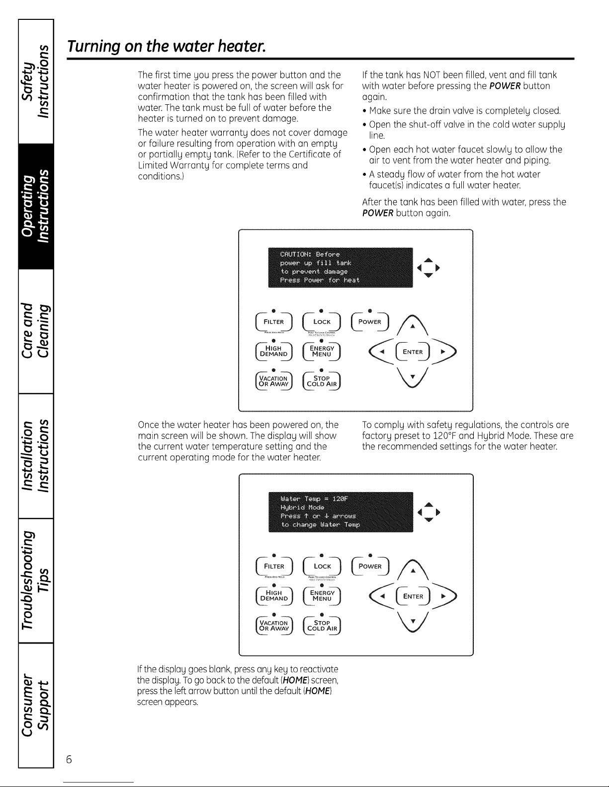
Turning on the water heater.
The first time you press the power button and the
water heater is powered on, the screen will ask for
confirmation that the tank has been filled with
water. The tank must be full of water before the
heater isturned on to prevent damage.
The water heater warrantg does not cover damage
or failure resulting from operation with an emptg
or partiallg emptg tank. (Referto the Certificate of
Limited Warrantg for complete terms and
conditions.)
o
q:r:D
O
If the tank has NOTbeen filled, vent and fill tank
with water before pressing the POWERbutton
again.
• Hake sure the drain valve is completelg closed.
• Open the shut-off valve in the cold water supplg
line.
• Open each hot water faucet slowlg to allow the
air to vent from the water heater and piping.
• A steadg flow of water from the hot water
faucet(s) indicates a full water heater.
After the tank has beenfilled with water, pressthe
POWERbutton again.
A
V
Once the water heater has been powered on, the
main screen will be shown. The displag will show
the current water temperature setting and the
current operating mode for the water heater.
o
O
(--H'GH--h
t2 'A"j
CAT,O.--h
_OR AWAY___
Ifthe displaggoesblank,pressang kegto reactivate
the displag.Togo back to the default (HOME)screen,
pressthe left arrow button until the default (HOME)
screenappears.
Tocomplg with safetg regulations, the controls are
factorg preset to 120°F and Hgbrid Mode.These are
the recommended settings for the water heater.
A
,I
Y
6
Page 7
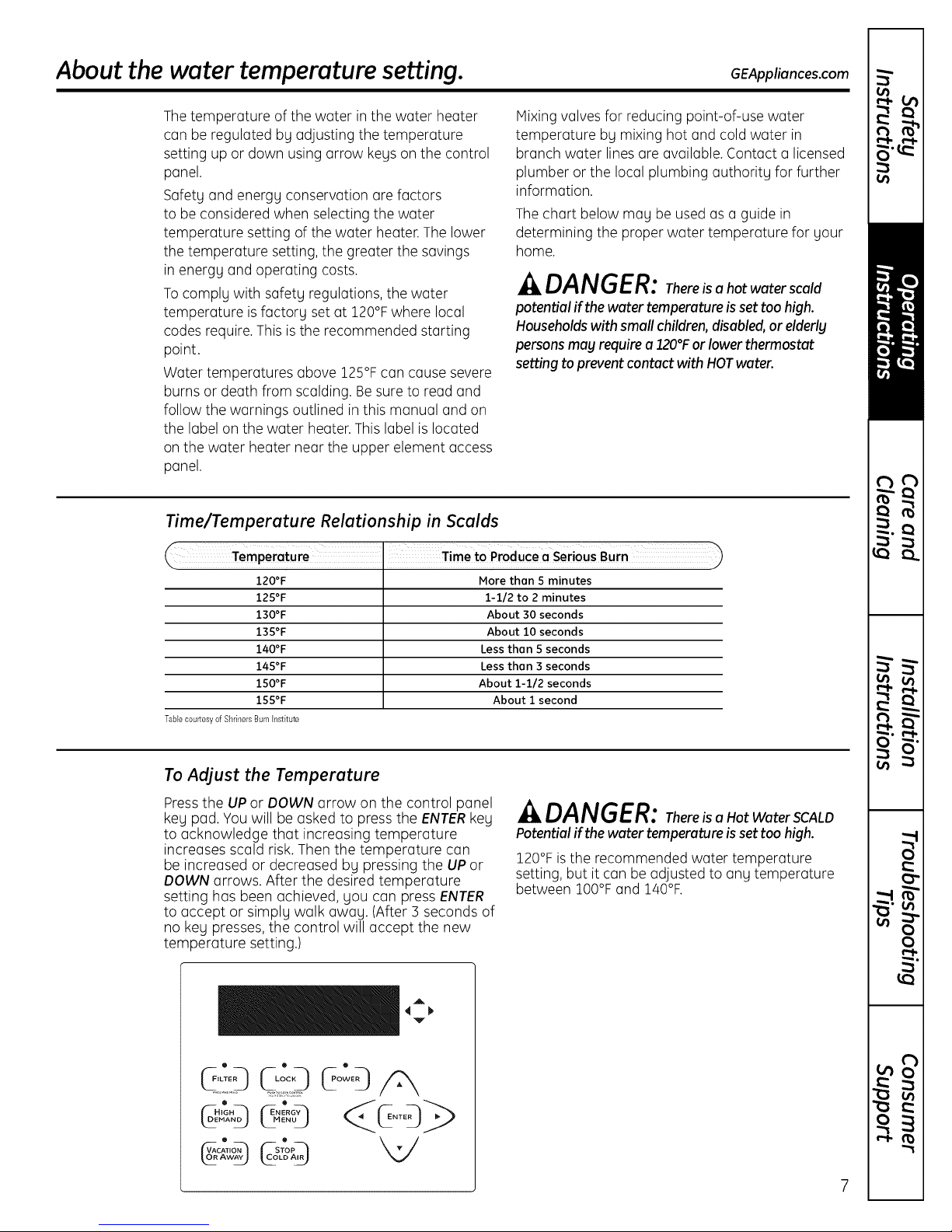
About the water temperature setting. GEAppliances.com
Thetemperature of the water in the water heater
can be regulated by adjusting the temperature
setting up or down using arrow kegs on the control
panel.
Safety and energy conservation are factors
to be considered when selecting the water
temperature setting of the water heater. The lower
the temperature setting, the greater the savings
Mixing valves for reducing point-of-use water
temperature by mixing hot and cold water in
branch water lines are available. Contact a licensed
plumber or the local plumbing authority for further
information.
The chart below may be used as a guide in
determining the proper water temperature for your
home.
in energy and operating costs.
Tocomply with safety regulations, the water
temperature isfactory set at 120°Fwhere local
codes require. This is the recommended starting
point.
Water temperatures above 125°F can cause severe
DANGER: Thereisahotwaterscald
poten_al if thewater temperatureis set toohigh.
Householdswith small children,disabled,or elderly
persons may requirea120°Forlowerthermostat
setting toprevent contactwith HOTwater.
burns or death from scalding. Besure to read and
follow the warnings outlined in this manual and on
the label on the water heater. This label is located
on the water heater near the upper element access
panel.
Time/Temperature Relationship in Scalds
_i TimetOProduceo SeriousBurn )
120°F
125°F
130°F
135°F
140°F
145°F
150°F
155°F
TabEecourtesvofShrinersBurnh_stitute
More thon 5 minutes
1-1/2 to 2 minutes
About 30 seconds
About 10 seconds
Less than 5 seconds
Less than 3 seconds
About 1-1/2 seconds
About i second
To Adjust the Temperature
Press the UP or DOWN arrow on the control panel
key pad, You will be asked to press the ENTERkey
to acknowledge that increasing temperature
increases scald risk. Then the temperature can
be increased or decreased by pressing the UPor
DOWN arrows. After the desired temperature
setting has been achieved, you can pressENTER
to accept or simply walk away. (After 3 seconds of
no key presses,the control will accept the new
temperature setting.)
• ® •
CL°:O /cX
MAND_ EN NT
. . _/
VA_._ATION _'_STO P_
DANGER: Thereisa HotWaterSCALD
Potentialif thewatertemperatureis set toohigh.
120°Fisthe recommended water temperature
setting, but it can be adjusted to any temperature
between 100°F and 140°F.
T
Page 8
Adjusting the water temperature and function mode.
This water heater defaults to the Hybrid operating
mode. The Hybrid mode isthe recommended
setting for this water heater, but can be changed
if desired. Available modes are listed below and
can be found under the ENERGYMENU button.
eHeat TM Mode
eHeatTM is the most energy-efficient mode for this
water heater. It takes heat from the surrounding
air to heat the water. The time it takes to heat
the water is longer in this mode, so it may NOT
be sufficient if you have a high-demand situation
such as a large household or company.
Standard Electric Mode
This mode uses only the upper and lower heating
resistance elements to heat the water. The time it
takes to heat the water is less in this mode, but it
isthe LEASTenergy-efficient mode.
Hybrid Mode--RECOMMENDED MODE
Hybrid mode combines the energy efficiency of
eHeatTM with the recovery speed and power of the
Standard Electric mode, with normal water usage.
High Demand
This mode is only necessary if your household
has a higher-than-average water usage or the unit
isundersized for the household water demands.
Inthis mode, the unit will use the electric heating
elements only when the water demand ishigher
than normal. When using the heating elements,
the water temperature will recover at a faster
rate but it will take more energy to heat it. Unlike
Standard Electric mode, it will use the heating
elements only when needed.
Toaccess any of these modes:
r_l Pressthe ENERGYMENU button and then
press ENTER.
_] Select "Operating Modes" on the menu list and
press ENTER.
Select the desired operating mode by using
the UPand DOWN arrow buttons and then
press ENTERagain.
Tocancel end return to the main energy menu:
Press the LEFTarrow button.
General navigation of energy menu:
F_For more information on each mode, while the
mode is highlighted, press the RIGHTarrow
button to read a description.
1-_1Use the UP and DOWN arrow buttons to scroll
through the description screens.
r_use the LEFT arrow button to return to the
"Operating Modes" menu list.
8
Page 9
About the feature buttons on the user interface. 6EAppliances.com
Vacation Or Away
This feature is used when you will be away from
the home for an extended period of time and hot
water is not needed. In this mode, the unit will
drop the water temperature down to 50°F and will
use the most efficient heating mode to conserve
energy while the heater is sitting idle. The unit will
automatically resume heating one day before
your return, so that hot water will be available.
For example if you will be gone 1/4days, press the
VACATIONORAWAY button, press the UParrow
button until the display reads 1/4days (the default
is 7 days) and press ENTER.The unit will drop
the water temperature down to 50°F for 13 days.
At the end of the 13th day, it will automatically
return to the previous operating mode and heat
the water to the original temperature setting.
The green light will be illuminated when this
feature is on.
Stop Cold Air
The Hybrid and eHeatTM modes save energy by
using heat from the air to heat the water. The
warm air is pulled through the system by fans
and is then cooled. That cool air then moves out
the back of the heater.
You can temporarily stop the cold air and fan
noise coming from the unit by pressing the STOP
COLDAIR button.
To adjust the number of days this feature will be
on, simply use the UP and DOWN arrow buttons
and press ENTER(the default is 3 days). The unit
will automatically return to the previous operating
mode after the number of days selected has
passed.
This mode should only be used on a temporary
basis because you do NOTget the energy savings
while in this mode.
The green light will be illuminated when this
feature is on.
High Demand (on some models)
This mode is only necessary if your household
has a higher-than-average water usage or
the unit is undersized for the household water
demands.
Inthis mode, the unit will use the electric heating
elements only when the water demand ishigher
than normal. When using the heating elements,
the water temperature will recover at a faster rate
but it will take more energy to heat it.
Unlike Standard Electric mode, it will use the
heating elements only when needed.
The green light will be illuminated when this
feature ison.
Control Lock
The control pad can be locked out to prevent
accidental key presses.
Simply press and hold the LOCI( button for three
seconds. The display will show "controls are
locked" and the green light will be illuminated
when this feature has been activated. No other
key presses will be allowed when the controls are
locked.
To deactivate the lock, press and hold the LOCI(
pad for three seconds. The green light will fade
and the screen will go to the default display.
Page 10
UsingtheEnerggMenu.
10
TheEnergyMenuisalsousedtochangethewaterheater
operatingmodes,to convertthetemperaturedisplayfrom
°Fto %,orto viewthe FAgs.Thereisalsoa Diagnostic
Menuthatisonlyaccessibleto a certifiedservice
technicianorplumberintheeventserviceisneeded.
Operating Modes
UsethisoptiontochangebetweeneHeatTM, Hybrid,
StandardElectricand HighDemandmodes(described
onpage8).
r_To access any of these modes, pressthe ENERGY
MENUbutton and then pressENTER.
_] elect Operating Modes on the menu listand
pressENTER.
r_ Selectthe desired operating mode by using the UPor
DOWNarrow buttons and then pressing ENTERagain.
[_-] Tocancel and return to the main EnergyMenu, press
the LEFTarrow button.
r_To getmoreinformationoneachmode,whilethe
modeishighlighted,presstheRIGHTarrowbutton
to reada description.
B-] Usethe UPorDOWNarrowbuttonstoscrollthrough
thedescriptionscreens.
E]Use the LEFTarrow buttonto returnto theOperating
Nodemenulist.
°Fand °CConversion
Thewatertemperaturedisplaywill defaultto °F.Toshow
thetemperaturesin °C,presstheENERGYMENUbutton;
thenpressENTER.Thesesettingswill beremembered
andreturnedfollowinga poweroutage.
r_-] PresstheDOWNarrowbuttontogoto "Choose°F
and°C"andpressENTER.
PressENTERto changefrom Fto C.Themainscreen
willthenbeshownwiththe temperaturein C.
r_To cancelandreturnto themainEnergyMenu,press
theLEFTarrowbutton.
o o
o
NOTE:Tochangebackto°F,repeatSteps1and 2.
Frequently Asked Questions
Thismenuitemanswersbasicquestionson coldair,
thefilter,operatingmodesandnoise.Allofthisinformation
iscoveredinthisUseandCaremanual.Ifthismanualis
misplaced,youcanrefertothissectionfor answers.
r_-]Toaccessthe FAQs,presstheENERGYMENUbutton
andthenpressENTER.
_] Pressthe DOWNarrowpadto goto "FAQs"andthen
pressENTER.
Therearefourquestioncategories:
ColdAir:
Q:Whyistherecoldair?
A:Hybrid,eHeatTM andHighDemandmodessaveenergy
by usingheatfromtheairto heatthewaterandthereby
coolingthesurroundingair.Thisgivessizableenergy
savings.
Q:Howto stopcoldair?
A:Pressthe STOPCOLDAIRbuttononthe keypad.This
reducesthe efficiencyofthe heater.Unitwill change
backto previousmodeafternumberof daysselected.
Filter:
Q:Whyisthereafilter?
A:In HybridandeHeatTM the unitmovesairthroughthe
system.Thefilterprotectsthe unitfromdirt.Acleanair
filter improvesefficiency.
Q:Howto cleanthefilter?
A:Leavepoweronandremovefilterfromtop of unit.Filter
canbewipedcleanorrinsedwithwarmwater.Adirty
filterwillreducewaterheaterefficienc!!
Modes:
Q:Whatis HighDemand?
A:HighDemandcanbeusedwhenhotwater usageis
higherthan normal.Theunitwillbelessefficientbutwill
heatwaterfasterinresponseto longwaterdraws.Forall
normaldraws,the unitwillstilluseefficienteHeatTM.
Q:Whatis StopColdAir?
A:Thismodewillstopcoldairtemporarilybutreduces
theefficiencyoftheheater.Theunitwillchangeback
to thepreviousmodeafterthenumberofdaysselected.
Q:Whatis VacationOrAway?
A:Ifyou aregonefor anextendedperiod,thismode
lowersthe watertemperaturetoreduceenergyused.
Unitwillswitchtothe previousmodeonedaybefore
youget back.
Q:Whatis eHeatZM?
A:eHeatTM isthemost-efficientmode.Ittakesheatfrom
theairto heatwater,therebycoolingthe surroundingair.
Slowerrecoverybutmost-efficientmode.
Q:Whatis Hybrid?
A:TheHybridmodecombinesbenefitsof eHeatTM withthe
speedandpowerof StandardElectric.Thisprovidesgreat
performancewithlessenergy.(Recommendedmode.)
Q:Whatis StandardElectric?
A:StandardElectricmodeusesonly theresistanceheaters
to heatthe water.Thisgivesfasterhotwaterrecovery
than Hybridmode,but usesmoreenergy.
Noise:
Q:Whyistheunitnoisy?
A:Inthemostenergy-efficientmodes,eHeat TM, Hybrid
andHighDemand,the methodusedto heatthewater
generatessomenoise.Someamountoffan noiseis
normal.
I_1 Usethe UPorDOWNarrowbuttonsto selectthe
categorythatpertainsto yourquestionand press
ENTER.
I_-I Tocancelandreturnto themainEnergyMenu,press
theLEFTarrowbutton.
I_1 Oncethecategoryisselected,usethe UPor DOWN
arrowbuttonstoselectthe desiredquestionsand
pressENTER.
B-] Usethe UPorDOWNarrowbuttonsto readthrough
theinformationscreens.
E] Whendone,pressthe LEFTarrowbuttonto return
totheFAQsmenu.
Page 11
Demand Response. (onsome models) GEAppliances.com
The Hybrid Electric heat pump water heater is compatible
with the GEDemand Response (DR)module which can be
purchased separately. Contact your local utility or visit
www.GEApplionces.com/demond_response to
see if your area is using DRtechnology.
The followingdemand responsefeaturesareavailable
as part of a pilot test program with the local utility
company to help consumers reduce peak electricity
usage in the home.
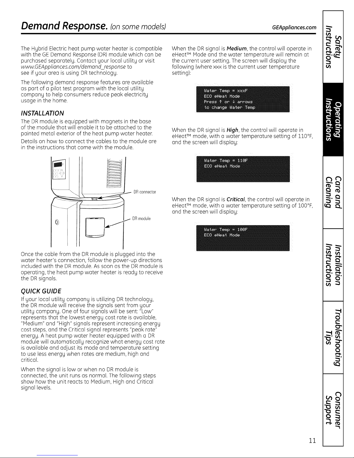
INSTALLATION
The DR module is equipped with magnets in the base
of the module that will enable it to be attached to the
painted metal exterior of the heat pump water heater.
Details on how to connect the cables to the module are
in the instructions that come with the module.
DR connector
DR module
When the DRsignal is Medium, the control will operate in
eHeatTM Mode and the water temperature will remain at
the current user setting. The screen will display the
following (where xxx isthe current user temperature
setting):
When the DRsignal is High, the control will operate in
eHeatTM mode, with a water temperature setting of 110°F,
and the screen will display:
When the DRsignal is Critical, the control will operate in
eHeatTM mode, with a water temperature setting of IO0°F,
and the screen will display:
Once the cable from the DR module is plugged into the
water heater's connection, follow the power-up directions
included with the DRmodule. As soon as the DRmodule is
operating, the heat pump water heater is ready to receive
the DRsignals.
QUICK GUIDE
If your local utility company is utilizing DRtechnology,
the DRmodule will receive the signals sent from your
utility company. One of four signals will be sent: "Low"
represents that the lowest energy cost rate isavailable,
"Medium" and "High" signals represent increasing energy
cost steps, and the Critical signal represents "peak rate"
energy. A heat pump water heater equipped with a DR
module will automatically recognize what energy cost rate
is available and adjust its mode and temperature setting
to use lessenergy when rates are medium, high and
critical.
When the signal is low or when no DRmodule is
connected, the unit runs as normal. The following steps
show how the unit reacts to Medium, High and Critical
signal levels.
11
Page 12
Careand cleaning of the water heater.
Routine Preventive Maintenance
^ DANGER: Beforemanuallyoperating
the relief valve, make certain no one will be
exposed to the danger of coming in contact with
the hot water released by the valve. The water
may be hot enough to create a scald hazard.
The water should be released into a suitable
drain to prevent injury or property damage.
NOTE: If the temperature and pressure-relief
valve on the hot water heater discharges
periodically, this mag be due to thermal expansion
in a closed water sgstem. Contact the water
supplier or gour plumbing contractor on how to
correct this. Do not plug the relief valve outlet.
Properlymaintained, your water heater will provide
years of dependable trouble-free service.
It issuggestedthat a routine preventivemaintenance
program be establishedand followed by the user.
Periodic Inspection:
It isfurther recommended that a periodic inspection
of the operating controls,heating elementsand
wiring should bemade by servicepersonnel
qualified in electric appliance repair.
Host electrical appliances,even when new,make
some sound when in operation. Ifthe hissing or
singing sound levelincreases excessively,the electric
heating element may requirecleaning. Contact a
qualified installer or plumber for inspection.
Temperature and Pressure-Relief Valve:
At least once a year, liftand release the lever handle
on the temperature and pressure-relief valve,located
on the back-right sideof the water heater,to make
certain the valve operates freely.Allow several
gallonsto flush through the discharge lineto an
open drain.
Flushing Tank:
A water heater's tank can act asa settling basin
for solids suspended in the water. It istherefore not
uncommon for hard water depositsto accumulate
in the bottom of the tank. Toclean the tank of these
deposits,open the drain valvelocated under the large
decorative cover near the bottom of the unit and
drain a few quarts of water from the water heater
every month.
12
Draining the Water Heater
CAUTION: Shut off powerto the
water heater before draining water.
DANGER:Beforemanuallyoperating
the relief valve, make certain no one will beexposed
to the hot water released by the valve. Thewater
drained from the tank mag be hot enough to
present a scald hazard and should be directed
to a suitable drain to prevent injury or damage.
Vacation and Extended Shutdown
If the water heater isto remain idle for an extended
period of time, the power and water to the
appliance should be turned off to conserve energy
and prevent a buildup of dangerous hydrogen
gas,
The water heater and piping should be drained if
they might be subjected to freezing temperatures.
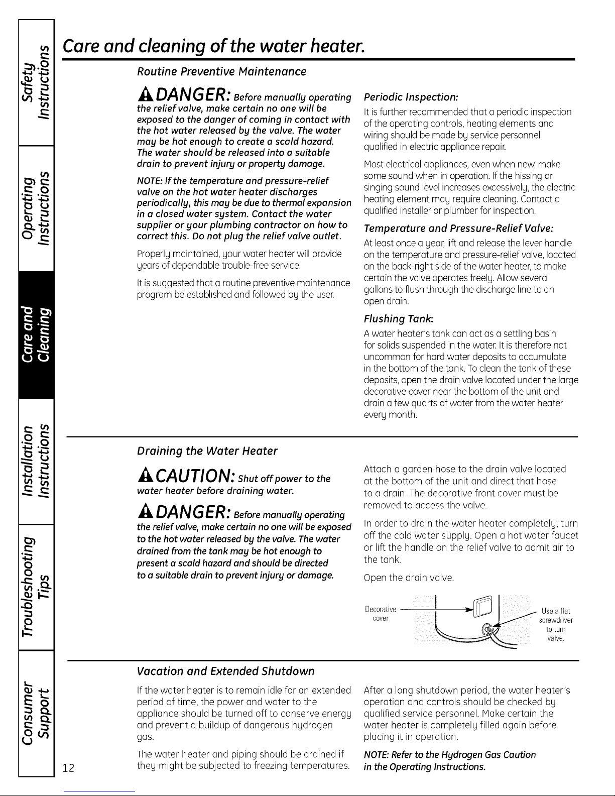
Attach a garden hose to the drain valve located
at the bottom of the unit and direct that hose
to a drain. The decorative front cover must be
removed to access the valve.
In order to drain the water heater completely, turn
off the cold water supply. Open a hot water faucet
or lift the handle on the relief valve to admit air to
the tank.
Open the drain valve.
Decorative
cover
After a longshutdown period, the water heater's
operation and controls should be checked by
qualified service personnel. Hake certain the
water heater is completely filled again before
placing it in operation.
NOTE:Referto the Hydrogen Gas Caution
in the Operating Instructions.
:> Usea flat
to turn
crewdr ver
valve.
Page 13
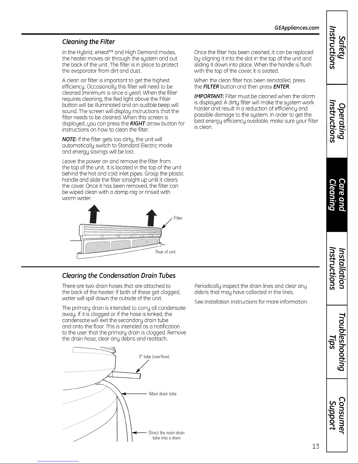
Cleaning the Filter
GEAppliances.com
Inthe Hybrid, eHeatTM and High Demand modes,
the heater moves air through the system and out
the back of the unit. The filter is in placeto protect
the evaporator from dirt and dust.
A clean air filter isimportant to get the highest
efficiency. Occasionally this filter will need to be
cleaned (minimum isonce a year).When the filter
requirescleaning, the Redlight above the Filter
button will be illuminated and an audible beep will
sound.Thescreen will display instructions that the
filter needs to be cleaned. When this screen is
displayed, you can pressthe RIGHTarrow button for
instructions on how to clean the filter.
NOTE:Ifthe filter gets too dirty, the unit will
automatically switch to Standard Electricmode
and energy savingswill be lost.
Leavethe power on and remove the filter from
the top of the unit. It is located in the top of the unit
behind the hot and cold inlet pipes.Grasp the plastic
handle and slidethe filter straight up until it clears
the cover.Once it has been removed, the filter can
be wiped cleanwith a damp rag or rinsedwith
warm water.
Oncethe filter has been cleaned, it can be replaced
by aligning it intothe slotin the top of the unit and
sliding itdown into place.When the handle isflush
with the top of the cover,it isseated.
When the clean filter has been reinstalled,press
the FILTERbutton and then pressENTER.
IMPORTANT:Filter must be cleaned when the alarm
isdisplayed.A dirty filter will make the system work
harder and resultin a reductionof efficiency and
possibledamage to the system. In order to get the
best energy efficiency available, make sure your filter
isclean.
Clearing the Condensation Drain Tubes
Thereare two drain hosesthat are attached to
the back of the heater. If both of theseget clogged,
water will spilldown the outside of the unit.
Theprimary drain isintended to carry allcondensate
away. If it isclogged or ifthe hoseis kinked,the
condensate will exitthe secondary drain tube
and onto the floor.This isintended as a notification
to the userthat the primary drain isclogged. Remove
the drain hose,clear any debris and reattach.
3" tube(overflow)
-- Main draintube
Directthemaindrain
tubeinto a drain
Periodicallyinspect the drain lines and clear any
debris that may have collected in the lines.
SeeInstallation Instructions for more information.
13
Page 14
Installation
Water Heater
Instructions
The location chosen for the water heater must take
into consideration the following:
I
LOCAL INSTALLATION REGULATIONS
This water heater must be installed in accordance with
these instructions, local codes, utility codes, utility
company requirements or,in the absence of local codes,
the latest edition of the National Electrical Code. It is
available from some local libraries or can be purchased
from the National FirePrevention Association,
Batterymarch park, Quincy, HA 02169 as booklet
ANSI/NFPA70.
POWER REQUIREMENTS
Check the markings on the rating plate of the water
heater to be certain the power supply corresponds to
the water heater requirements.
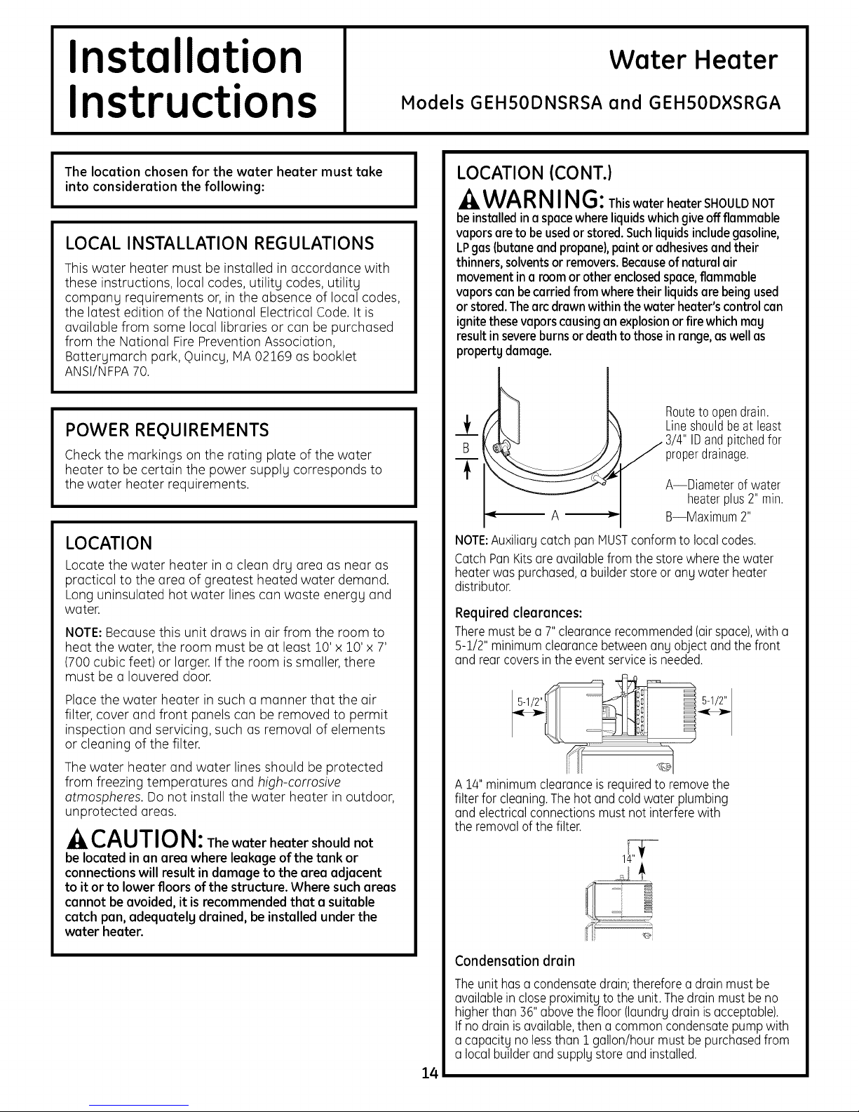
Models GEHSODNSRSA and GEHSODXSRGA
LOCATION (CONT.)
I
WAR NING:ThiswaterheaterSHOULDNOT
beinstalledin a spacewhereliquidswhichgive offflammable
vaporsareto beusedor stored.Suchliquidsincludegasoline,
LPgas(butaneandpropane),paint or adhesivesandtheir
thinners, solvents or removers. Because of natural air
movementina roomorotherenclosedspace,flammable
vaporscan becarriedfrom wheretheirliquidsare beingused
or stored.Thearc drawnwithinthewaterheater'scontrol can
ignitethesevaporscausinganexplosionorfire whichmay
resultin severeburns or deathtothoseinrange, aswellas
property damage.
Routeto opendrain.
Lineshouldbeat least
3/4" IDandpitchedfor
properdrainage.
A--Diameter of water
heaterplus2" min.
B--Maximum 2"
LOCATION
Locate the water heater in a clean dry area as near as
practical to the area of greatest heated water demand.
Long uninsulated hot water lines can waste energy and
water.
NOTE:Because this unit draws in air from the room to
heat the water, the room must be at least 10' x 10' x 7'
(700 cubic feet) or larger. Ifthe room issmaller, there
must be a Iouvered door.
Placethe water heater in such a manner that the air
filter, cover and front panels can be removed to permit
inspection and servicing, such as removal of elements
or cleaning of the filter.
The water heater and water lines should be protected
from freezing temperatures and high-corrosive
atmospheres. Do not install the water heater in outdoor,
unprotected areas.
CAUTION: The water heater should not
be located in an area where leakage of the tank or
connections will result in damage to the area adjacent
to it or to lower floors of the structure. Where such areas
cannot be avoided,it is recommended that a suitable
catch pan, adequately drained, be installed under the
water heater.
NOTE:Auxiliarycatch pan MUSTconformto localcodes.
CatchPanKitsare availablefromthe store wherethe water
heaterwas purchased,abuilderstoreor any water heater
distributor.
Required clearances:
Theremust be a 7"clearancerecommended(airspace),with a
5-1/2" minimum clearancebetweenany object andthe front
and rear coversin the event serviceisneeded.
A 14"minimum clearanceis requiredto removethe
filter for cleaning.Thehot and coldwater plumbing
and electricalconnectionsmust notinterferewith
the removalofthe filter.
Condensation drain
Theunit has a condensatedrain;therefore a drain must be
availablein closeproximity to the unit. Thedrain must be no
higherthan 36"abovethe floor (laundrydrain isacceptable).
If no drain isavailable,then a commoncondensatepump with
a capacity no lessthan I gallon/hourmust bepurchasedfrom
a localbuilderand supply store and installed.
14
Page 15
Installation Instructions
THERMAL EXPANSION
AWARNI NG:The water heater should not
be installed in a space where liquids which give off
flammable vapors are to be used or stored.
Determine if a check valve exists in the inlet water line.
It may have been installed in the cold water line as a
separate backflow preventer, or it may be part of a
pressure-reducing valve, water meter or water softener.
A check valve located in the cold water inlet line can
cause what isreferred to as a "closed water system."
A cold water inlet line with no check valve or backflow
prevention device isreferred to as an "open" water
system.
Aswater isheated, it expands in volume and creates an
increase in the pressurewithin the water system. This
action is referred to as "thermal expansion." Inan "open"
water system, expanding water which exceeds the
capacity of the water heater flows back into the city main
where the pressure is easily dissipated.
A "closed water system," however, prevents the
expanding water from flowing back into the main supply
line,and the result of "thermal expansion"can create a
rapid and dangerous pressure increase inthe water
heater and system piping. This rapid pressure increase
can quickly reach the safety setting of the relief valve,
causing it to operate during each heating cycle. Thermal
expansion, and the resulting rapid and repeated
expansion and contraction of components in the water
heater and piping system, can cause premature failure of
the relief valve, and possibly the heater itself. Replacing
the relief valve will not correct the problem!
The suggested method of controlling thermal expansion is
to install an expansion tank inthe cold water line between
the water heater and the check valve (refer to the
illustration on right). The expansion tank isdesigned with
an air cushion built in that compresses as the system
pressure increases, thereby relieving the over-pressure
condition and eliminating the repeated operation of the
relief valve. Other methods of controlling thermal
expansion are also available. Contact your installing
contractor, water supplier or plumbing inspector for
additional information regarding this subject.
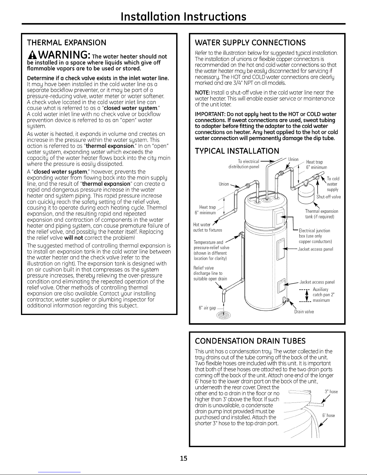
WATER SUPPLY CONNECTIONS
Referto the illustrationbelowfor suggestedtypical installation.
Theinstallationof unionsor flexiblecopperconnectors is
recommendedon the hot and coldwater connectionsso that
thewater heatermay beeasilydisconnectedforservicingif
necessary.TheHOTand COLDwater connectionsare clearly
marked and are 3/4" NPTonallmodels.
NOTE:Installa shut-off valvein the cold water linenear the
water heater.Thiswill enable easierservice or maintenance
of the unit later.
IMPORTANT: Do not apply heat to the HOT or COLD water
connections. If sweat connections are used, sweat tubing
to adapter before fitting the adapter to the cold water
connections on heater. Any heat applied to the hot or cold
water connection will permanently damage the dip tube.
TYPICAL INSTALLATION
Toelectrical Union
distributionpanel 6" minimum
Union
Heattrap
6" minimum
Hotwater
outlet tofixtures
Temperatureand
pressure-reliefvalve
(shownin different
locationfor clarity)
Reliefvalve
dischargeline to
suitable opendrain
j Heat trap
supply
Shut-offvalve
Thermalexpansion
tank(if required)
junction
box(useonly
copperconductors)
--Jacket accesspanel
panel
---i- Auxiliary
:_ catchpan 2"
_._J__ maximum
Drainvalve
CONDENSATION DRAIN TUBES
Thisunit hasacondensationtray. Thewater collected inthe
tray drains out ofthe tubecoming off the back of the unit.
Two flexiblehosesare includedwith thisunit. Itis important
that both of these hosesare attachedto the two drainports
coming off the back ofthe unit.Attach one end ofthe longer
6' hoseto thelower drainporton the back of the unit,
underneaththe rearcover.Directthe
other endto a drain in thefloor or no s" hose
higherthan 3'above thefloor.Ifsuch
drain isunavailable,a condensate
drain pump (notprovided)must be
purchasedand installed.Attachthe 6' hose
shorter3" hoseto thetop drain port.
15
Page 16
Installation Instructions
A new combination temperature and pressure-reliefvalve,
complging with the Standardfor ReliefValvesand
Automatic GasShut-Off Devicesfor Hot Water Supplg
Sgstems,ANSIZ21.22,issupplied and must remain installed
in the opening provided and marked for the purpose on the
water heater.No valve of ang tgpe should be installed
between the reliefvalve and the tank. Localcodes shall
govern the installation of relief valves.
RELIEF VALVE
A WARNING:Thepressurerating oftherelief
valve must not exceed 150PSI,the meximum working
pressure of the weter heeter es merked on the rating
plete.
TheBTUH rating of the reliefvalve must not belessthan the
input rating of the water heater as indicated on the rating
label located onthe front of the heater (1watt=3.412 BTUH).
Connectthe outlet of the reliefvalve to a suitable open drain
sothat the discharge water cannot contact liveelectrical
parts or personsand to eliminate potential water damage.
Pipingusedshould beof a tgpe approved for hot water
distribution. Thedischarge linemust be no smaller than the
outlet of the valve and must pitch downward from the valve
to allow complete drainage (bg gravitg) of the reliefvalve
and discharge line.Theend of the discharge lineshould not
be threaded or concealed and should be protected from
freezing.No valve of ang tgpe, restriction or reducer
coupling should be installed in the discharge line.
kCAUTION:
To reduce the risk of excessive pressures and
temperatures in this water heater, install temperature
and pressure protective equipment required bg local
codes and no less than a combination temperature and
pressure relief valve certified bg a nationallg recognized
testing laboratorg that maintains periodic inspection of
production of listed equipment or materials, as meeting
the requirements for ReliefValves and Automatic Gas
Shutoff Devices for Hot Water Supplg Sgstems, ANSI
Z21.22.This valve must be marked with a maximum set
pressure not to exceed the marked maximum working
pressure of the water heater. Install the valve into an
opening provided and marked for this purpose in the
water heater, and orient it or provide tubing so that ang
discharge from the valve exits onlg within 6 inches above,
or at ang distance below, the structural floor, and does
not contact ang live electrical part. The discharge
opening must not be blocked or reduced in size under
ang circumstances.
TO FILL THE WATER HEATER
A WA RNING:Thetankmustbefullofwater
beforeheeter isturned on.The water heeter werrentg
doesnot coverdamage or failure resultingfrom
operationwith an emptg or partiallg emptg tank.
Make certain the drain valve is completelg closed,
Open the shut-off valve in the cold water supplg line.
Open each hot water faucet slowlg to allow the air to
vent from the water heater and piping.
A steadg flow of water from the hot water faucet(s)
indicates a full water heater.
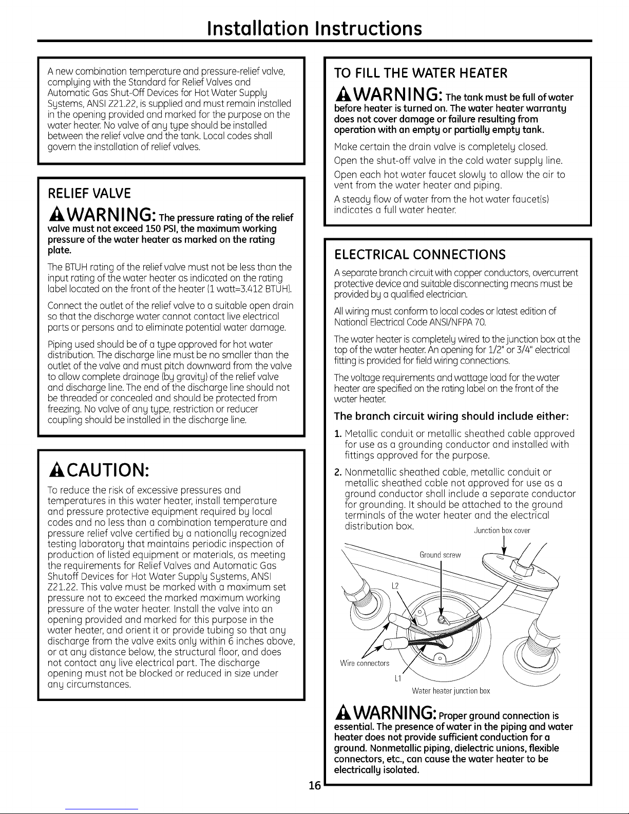
ELECTRICAL CONNECTIONS
Aseparate branch circuitwith copper conductors,overcurrent
protectivedeviceand suitabledisconnectingmeans mustbe
providedbg a qualifiedelectrician.
Allwiringmust conform to local codesor latesteditionof
National ElectricalCodeANSI/NFPA70.
Thewater heateriscompletelgwiredto thejunction boxat the
top ofthe water heater.An openingfor 1/2"or 3/4"electrical
fittingis providedforfieldwiring connections.
Thevoltagerequirementsand wattage loadforthe water
heaterare specifiedonthe ratinglabelon thefront ofthe
water heater.
The branch circuit wiring should include either:
1. Metallic conduit or metallic sheathed cable approved
for use as a grounding conductor and installed with
fittings approved for the purpose.
2. Nonmetallic sheathed cable, metallic conduit or
metallic sheathed cable not approved for use as a
ground conductor shall include a separate conductor
for grounding. It should be attached to the ground
terminals of the water heater and the electrical
distribution box. ,]unctionboxcover
Groundscrew
Wire connectors
L1
Waterheaterjunction box
^_ WARNING:Proper ground connection is
essential. The presence of water in the piping and water
heater does not provide sufficientconduction for a
ground. Nonmetallic piping, dielectric unions, flexible
connectors, etc., can cause the water heater to be
electricallg isolated.
16
Page 17
Installation Instructions
The manufacturer's warranty does not cover any
damage or defect caused by installation, attachment or
use of any type of energy-saving or other unapproved
devices (other than those authorized by the
manufacturer) into, onto or in conjunction with the water
heater. The use of unauthorized energy-saving devices
may shorten the life of the water heater and may
endanger life and property.
The manufacturer disclaims any responsibility for
such loss or injury resulting from the use of such
unauthorized devices.
If local codes require external application of insulation
blanket kits, the manufacturer's instructions included
with the kit must be carefully followed.
Application of any external insulation, blankets or
water pipe insulation to this water heater will require
careful attention to the following:
• Do not cover the temperature and pressure-relief
valve,
• Do not cover access panels to the heating elements.
• Do not cover the electrical junction box of the
water heater.
• Do not cover the operating or warning labels attached
to the water heater or attempt to relocate them on
the exterior of the insulation blanket.
• Do not block the air inlet outlets below and in the top
covers.
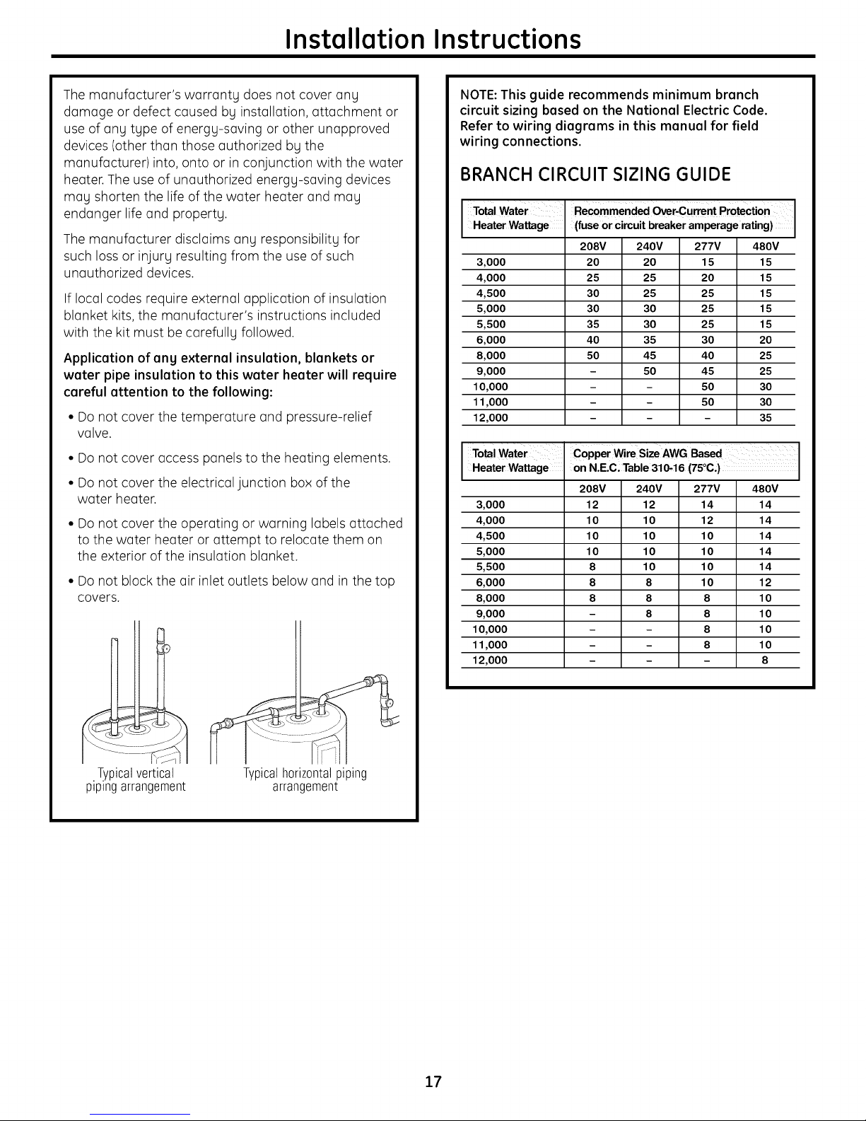
NOTE:This guide recommends minimum branch
circuit sizing based on the National Electric Code.
Refer to wiring diagrams in this manual for field
wiring connections.
BRANCH CIRCUIT SIZING GUIDE
I Total Water Recommended _r-current Protection
Heater Wattage (fuse or c rcu t breaker amperage rat ng)
208V 240V 277V 480V
3,000
4,000
4,500
5,000
5,500
6,000
8,000
9,000
10,000
11,000
12,000
Heater Wattage
I Total Water
3,000
4,000
4,500
5,000
5,500
6,000
8,000
9,000
10,000
11,000
12,000
20 20 15 15
25 25 20 15
30 25 25 15
30 30 25 15
35 30 25 15
40 35 30 20
50 45 40 25
- 50 45 25
- 50 30
- 50 30
- - 35
icopper wire Size AWG B2ed
on N.E.C, Tabe31_16(75 C,)
208V 240V 277V 480V
12 12 14 14
10 10 12 14
10 10 10 14
10 10 10 14
8 10 10 14
8 8 10 12
8 8 8 10
8 8 10
- 8 10
- 8 10
-- -- 8
•Typicalvertical
p_p_ngarrangement
Typicalhorizontalpiping
arrangement
17
Page 18
Installation Instructions
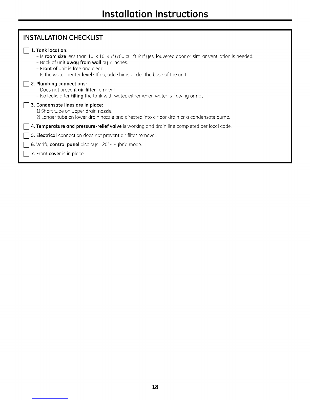
INSTALLATION CHECKLIST
[] 1. Tank location:
- Is room size lessthan 10' x 10' x 7' (700 cu.ft.)? If yes, Iouvered door or similar ventilation is needed.
- Back of unit away from wall by 7 inches.
- Front of unit isfree and clear.
- Is the water heater level? If no, add shims under the base of the unit.
[] 2. Plumbing connections:
- Does not prevent air filter removal.
- No leaks after filling the tank with water, either when water is flowing or not.
[] 3. Condensate lines are in place:
1)Short tube on upper drain nozzle.
2) Longer tube on lower drain nozzle and directed into o floor drain or a condensate pump.
[] 4. Temperature and pressure-relief valve isworking and drain line completed per local code.
[] 5. Electrical connection does not prevent air filter removal.
[] 6. Verify control panel displays 120°F Hybrid mode.
[] 7. Front cover is in place.
18
Page 19
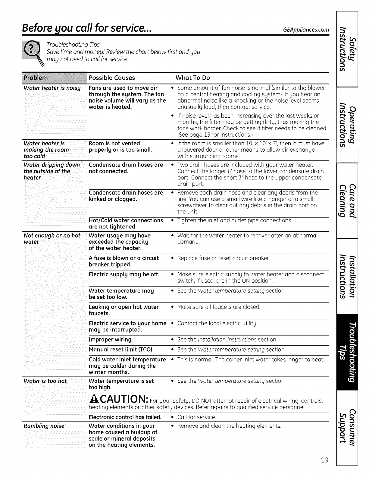
Beforeyou call for service... GEAppliances.com
Troubleshooting Tips
Save time and moneg! Review the chart below first and gou
may not need to call for service.
b_ Possible Causes
Water heater is noisg Fans are used to move air
through the sgstem. The fan
noise volume will varg as the
water is heated.
Water heater is Room is not vented • Ifthe room issmaller than 10' x 10' x 7',then it must have
making the room properlg or is too small, a Iouvered door or other means to allow air exchange
too cold with surrounding rooms.
Water dripping down Condensate drain hoses are • Two drain hoses are included with your water heater.
the outside of'the not connected. Connect the longer 6' hose to the lower condensate drain
heater port. Connect the short 3" hose to the upper condensate
Condensate drain hoses are • Remove each drain hose and clear any debris from the
kinked or clogged, line. You can use a small wire like a hanger or a small
Hot/Cold water connections • Tighten the inlet and outlet pipe connections.
are not tightened.
Not enough or no hot Water usage mag have • Wait for the water heater to recover after an abnormal
water exceeded the capacitg demand.
of the water heater.
What To Do
• Some amount of fan noise is normal (similar to the blower
on a central heating and cooling system). If you hear an
abnormal noise like a knocking or the noise level seems
unusuallu loud, then contact service.
• Ifnoise level has been increasing over the last weeks or
months, the filter may be getting dirty, thus making the
fans work harder. Check to see if filter needs to be cleaned.
(Seepage 13 for instructions.)
drain port.
screwdriver to clear out any debris in the drain port on
the unit.
A fuse is blown or a circuit • Replace fuse or reset circuit breaker.
breaker tripped.
Electric supplg mag be off. • Hake sure electric supply to water heater and disconnect
switch, if used, ore in the ON position.
Water temperature mag • See the Water temperature setting section.
be set too low.
Leaking or open hot water • Hake sure all faucets ore closed.
faucets.
Electric service to gour home • Contact the local electric utility.
mag be interrupted.
Improper wiring. • See the Installation Instructions section.
Manual reset limit (TCO). • See the Water temperature setting section.
Cold water inlet temperature • This is normal. The colder inlet water takes longer to heat.
mag be colder during the
winter months.
Water is too hot Water temperature isset • See the Water temperature setting section.
too high.
-4,CAUTION: Foryoursafety,oONOTattemptrepairofelectricalwiring, controls,
heating elements or other safety devices. Refer repairs to qualified service personnel.
Electronic control hasfailed. • Call for service.
Rumbling noise Water conditions in gour • Remove and clean the heating elements.
home caused a buildup of
scale or mineral deposits
on the heating elements.
19
Page 20
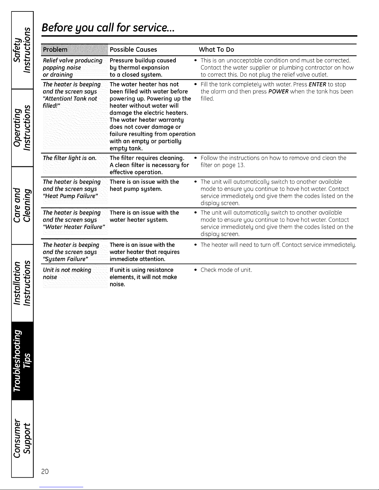
Before you call for service...
_ir_i:i i::i:_:i_ii!i Possible causes
Relief valve producing
popping noise
or draining
The heater is beeping
and the screen sags
"Attention! Tank not
filled!"
The filter light is on.
The heater is beepin:
and the screen sags
Pressure buildup caused
bg thermal expansion
to a closed sgstem.
The water heater has not •
been filled with water before
powering up. Powering up the
heater without water will
damage the electric heaters.
The water heater warrantg
does not cover damage or
failure resulting from operation
with an emptg or partially
emptg tank.
The filter requires cleaning. •
A clean filter is necessary for
effective operation.
There is an issue with the •
heat pump system.
"Heat Pump Failure"
The heater is beepinc There isan issue with the
and the screen sags water heater sgstem.
"Water Heater Failure"
Theheater is beeping
and the screen sags
"Sgstem Failure"
Unit is not making
noise
There isan issuewith the
water heater that requires
immediate attention.
If unit isusing resistance
elements, it will not make
noise.
What To Do
• Thisis an unacceptable condition and must be corrected.
Contact the water supplier or plumbing contractor on how
to correct this. Do not plug the relief valve outlet.
Fillthe tank completely with water. PressENTERto stop
the alarm and then press POWERwhen the tank has been
filled.
Follow the instructions on how to remove and clean the
filter on page 13.
The unit will automaticallu switch to another available
mode to ensure you continue to have hot water. Contact
service immediately and give them the codes listed on the
display screen.
The unit will automatically switch to another available
mode to ensure you continue to have hot water. Contact
service immediately and give them the codes listed on the
display screen.
• The heater will need to turn off. Contact service immediately.
Check mode of unit.
20
Page 21
Notes.
GEAppliances.com
t'h tl_ "
gl
_ _'22_
v _
_ ¢Pi
21
w
u
v
o
Page 22

GEHgbfid Water Heater Warrants.
All warrantg service provided bg our Authorized Servicer Network.
To schedule service, call 888.4GE.HEWH (888./443.4394). Please
have serial number and model number available when calling for
service.
For The Period Of: We Will Replace:
One Year Any part of the HgbridWater Heater which failsdue to a defect inmaterials or workmanship.
Fromthe dote of the Duringthis limited one-year warranty, GEwill alsoprovide, free of charge, alllabor and related
original purchase serviceto replacethe defective part.
Second through
Tenth Year
From the dote of the
original purchase
What Is Not Covered:
• Service trips to sour home to teach SOUhow to use
the product.
• Improper installation, delivers or maintenance.
• Failure of the product if it isabused, misused, altered,
used commerciallg or used for other than the intended
purpose.
• Use of this product where water is microbiologicallg
unsafe or of unknown qualitg, without adequate
disinfection before or after the sgstem.
• Replacement of housefusesor resetting of circuit breakers.
• Damage to the product caused bg accident, lightning,
fire, flood or acts of God.
• Incidental or consequential damage caused bg possible
defects with this appliance,its installation or repair.
• Product not accessibleto provide required service.
• If product removed from original installation location.
Any part of the HgbridWater Heater which failsdue to a defect inmaterials or workmanship.
Duringthis limited ten-year parts warranty, labor and related serviceto replacethe defective part
are not included.
• Damages, malfunctions or failure caused bgthe use
of unapproved parts or components.
• Damages, malfunctions or failure caused bg operating
the heat pump water heater with the anode rod
removed.
• Damages, malfunctions or failure resulting from
operating the heat pump with an emptg or partiallg
emptg tank.
• Damages, malfunctions or failure caused bg subjecting
the tank to pressure greater than those shown on the
rating label.
• Damages, malfunctions or failure caused bgoperating
the heat pump water heater with electrical voltage
exceeding those shown on the rating label.
• Water heater failure due to the water heater being
operated in a corrosive atmosphere.
Staple Four receipt here.
Proof of the original purchase
date is needed to obtain service
under the warrant F.
EXCLUSION OF IMPLIED WARRANTIES--Your sole and exclusive remedg isproduct repair as provided in
this Limited Warrantg. Ang implied warranties, including the implied warranties of merchantabilitg or
fitness for a particular purpose, are limited to one gear or the shortest period allowed bg law.
This warrants is extended to the original purchaser and ang succeeding owner for products purchased for home use
within the USA. If the product is located in on area where service bg a GEAuthorized Servicer isnot available, Sou mug
be responsible for a trip charge or Sou mug be required to bring the product to on Authorized GEService locution for
service. InAlaska, the warrants excludes the cost of shipping or service coils to sour home.
Some states do not allow the exclusion or limitation of incidental or consequential damages. This warrants
gives gou specific legal rights, and gou mug also have other rights which varg from state to state. To know
what sour legal rights are, consult sour local or state consumer affairs office or sour state's Attomeg General.
Warrantor: General Electric Compang. Louisville, KY 40225
22
II
Page 23

m
Information sur
la s_curit_ .................. 24,25
Instructions
de fonctionnement ....... 26 _33
Entretien et nettoyage ..... 34,35
Instructions
d'installation .............. 36 _4o
Conseils de d_pannage .... 41, 42
Soutien au
consommateur ............. 43, 44
1/1
iJr]
_ url
_ v
Inscrivez les num_ros de module
et de s_rie ici :
N° de module
N° de s_rie
Vousles trouverez sur I'_tiquette de
classification _ I'avantde votre chauffe-eau.
_ vm
,,-4. L,Ir]
v _
vJ
f_ m
o
23
Page 24

INFORMATION IMPORTANTESURLA SECURITE.
LISEZ TOUTES LES INSTRUCTIONS AVANT L'UTILISATION.
AVERTISSEHENT!
Pour votre s_curit_,vous devez suivre les instructions contenues duns ce manuel pour r_duire les risques d'incendie ou
d'explosion,d'_lectrocution ou pour pr_venir les dommages materiels, les blessures ou lu mort.
Assurez-vousde lire et de comprendre tout le manuel de I'utilisateur avant de tenter d'installer ou defaire fonctionner ce
chuuffe-eau. Vous sauverezdu temps et de I'argent. Accordez une attention toute particuli_re aux directivesde s_curit_.
Tout manquement 6 ces avertissements peut occasionner des blessuresgravesou lu mort. Sivous avez de lu difficult6
6 comprendre lesinstructions contenues duns ce manuel ou sivous avezdesquestions, ARRETEZet demandez de I'aide
6 un technicien qualifi_ ou6 votre fournisseur d'_lectricit_.
REGLAGE DE LA TEMPERATURE DE L'EAU
La s_curit_ et lu conservation de I'_nergie sont desfacteurs 6 consid_rer Iorsdu r_gluge de la temp6rature de I'eau 6 I'aidede
I'interface utilisateur du chauffe-eau. Une temperature de I'eau sup_rieure 6 52°C(125 °F)peut causer des brOluresgraves ou
la mort par _bouillantage. Assurez-vousde lire et de suivre lesavertissements exposes sous I'image de I'_tiquette ci-dessous.
¢ette _tiquette est _galement sur le chuuffe-eau pros du dessusdu r_servoir.
IIsevend desm_langeurs qui r_duisent la temp6rature de I'eau
au point d'utilisation en m_langeant de I'euufroide 6 I'euuchuude
duns lescunulisutions dedistribution. Communiquezuvec un
plombier certifi_ ouI'uutorit_ en plomberie pour plus
d'informution.
Relation temperature/temps pour les br_lures
L'eau b une temperature sup_rieure
52 °C (125°F) peat causer
instantan_ment des br_lures
graves ou la mort par _bouillantage.
Le r_glage de la commande
_lectronique de temperature est
habituellement proche de la
temperature de I'eau au robinet.
Toutefois, certains facteurs peuvent
causer une hausse de la temperature
de I'eau pouvant aller jusqu'_ 71 °C,
pea importe le r_glage de la
commande. Touchez toujours
I'eau avant de vous baigner ou
de prendre votre douche.
Les enfants et les personnes
handicap_es ou _g_es sont plus
b risque de s'_bouillanter.
Consultez les instructions contenues
dans ce manuel avant de r_gler
la temperature du chauffe-eau.
Touchez Yeau avant de vous baigner
ou de prendre votre douche.
Des valves de limitation de
la temperature sont vendues;
consultez ce manuel.
Temp(_reture TempsPouiproduireunebiulure grove_
49 °C (120 °F}
52 °C (125 °F}
54 °C (130 °F}
57 °C (135 °F}
60 °C (140 °F}
63 °C (145 °F)
66 °C (150 °F)
68 °C (155 °F}
TableaucourtoisieduShrinersBumh_stitute
Plus de 5 minutes
1-112 6 2 minutes
Environ 30 secondes
Environ 10 secondes
Moins de 5 secondes
Moins de 3 secondes
Environ 1-1/2 seconde
Environ i seconde
Vouspouvez utiliser le tubleuu ci-dessuscomme pour
d_terminer la bonne temp_ruture de I'euupour votre muison.
REMARQUE:Les m_nages avec des petits enfants ou
despersonnes handicap_es ou 6g_es peuvent n_cessiter
un r_glage du thermostat 6 49 °C(120°FIou moins pour
pr_venir le contact avec de I'eau TROPCHAUDE.
DANGER :, e×isteunepossibilit_ de
S'EBOUILLANTERsi lechauffe-eau est r_gl_ _ une
temperature trop _lev_e.
CONSERVEZ CES INSTRUCTIONS
Page 25

www.electromenogersge.co
,AVERTISSEHENT!
L'essence ainsi que d'autres substances et
liquides inflammables (adh#sifs, solvants, etc.)
et les #manations qu'ils produisant sont
extr_mement dangereux. NEPASmanipuler,
utiliser ou entreposer de I'essence ou d'autres
substances inflammables ou combustibles pros
d'un chauffe-eau. L'arc#lectrique a I'int#rieur
de la commande du chauffe-eau peut allumer
ces #manations. Le manquement _ cette directive
peut entraTner des dommages materiels, des
blessures ou la mort.
_ILPOUR INSTALLATIONS DANS
L'_'TATDE CALIFORNIE
Les lois de IoColifornie exigent que les chouffe-
eou r#sidentiels soient fixes, oncr#s ou ottoch#s
pour qu'ils ne tombent pos et qu'ils r#sistent
oux mouvements horizontoux cous#s por
les tremblements de terre. Pour les chouffe-eou
r#sidentiels d'une copocit# inf#rieure _ 197 litres
(52 gollons), vous pouvez vous procurer une
brochure avec des instructions g#n#riques de
fixotion pour les tremblements de terre en vous
odressont _ :Office of the Stote Architect, 400 P
Street, Socromento, CA 95814 ou vous pouvez
t_l_phoner ou 916.324.5315 ou demonder
un distributeur de chouffe-eau.
Cependont, ce sont les codes municipoux
opplicobles qui r#gissent I'instollotion. Pour
les chouffe-eou r6sidentiels d'une copocit#
sup#rieure _ 197 litres (52 gollons), odressez-
vous oux outorit#s municipoles pour connoTtre
les procedures de fixotion occeptobles.
Avertissement en vertu de la Proposition 65
de la Californie : Ce produit contient des produits
chimiques connus dans I'_tat de Californie comme
causant le cancer, les malformations et autres
d_fauts de naissance.
LISEZETSUIVEZATTENTIVEMENTCESDIRECTIVESDESL-CURITL-.
CONSERVEZ CES INSTRUCTIONS
25
Page 26

Fonctionnement du chauffe-eau.
A AVERTISSEM EN T : Lesyst_me d'eau chaude desservipar ce chauffe-eau peut produire de I'hydrog_ne
s'iln'a pas_t_ utilis_ pendant uneIongue p@iodede temps (g_n@alementdeu× semainesou plus).L'HYDROGENEESTUNGAZ
EXTREMEMENTINFLAMMABLE!Pourdissipercegaz et pour r_duire le risquede blessure,ilest recommand_ d'ouvrir le robinet
d'eau chaude pendant plusieurs minutes 6 I'_vierde lacuisine avant d'utiliser un appareil _lectrique raccord_ au syst_me d'eau
chaude. S'ily a de I'hydrog_ne dans lesyst_me, ily aura un bruit inhabituel comme deFairqui s'_chappe par letuyau quand
I'eaucommencera 6 couler.Nepas fumer ou utiliserune flamme nue prosdu robinet Iorsquevous I'ouvrez.
Pr@coutions de s@curit@
kAVERTISSEMENT:
Si le chuuffe-euu u @t@soumis
une inondution, un incendie ou
des dommuges mut@riels,coupez
I'ulimentution du chuuffe-euu en
@lectricit@et en euu.
Ne pas utiliser le chauffe-eau
tant qu'il n'a pas @t@compl@tement
v@rifi@par un technicien de service
qualifi&
A. Couper lecourant du chauffe-eau
sicelui-cia subi un surchauffage,
un incendie,une inondation ou
desdommages materiels.
B.Nepas allumer lechauffe-eau s'il n'est
pas rempli d'eau
C.Nepas allumer lechauffe-eau silavalve
d'interruption d'eau froide est ferm@e.
D. Nepas entreposer ou utiliserd'essence
ou autres substances,@manationsou
liquidesinflammables, comme des
adh@sifsou du dissolvant a peinture,
dans lesparages de cet appareil ou
de tout autre appareil @lectrique.
Sivous devez utiliserces substances
inflammables, ouvrez lesportes et
lesfen@trespourde la ventilation.
Commandes de s@curit@
Cechauffe-eau est@quip_de deux
commandes de limitation de la temp6rature
(CLT)qui sontsitu@sau-dessusde I'@l@ment
chauffant en contactavec lasurface du
r6servoir.Sipour quelqueraisonque ce soit
latemperature de I'eaudevient beaucoup
trop chaude,la commande de limitation
de la temp@ature(CLT)coupelecircuit
@lectriquede I'@l@mentchauffant. Unefois
que cette commande estenclench@e,elle
doit @trer_initialis_emanuellement.La
r_initialisationdescommandes de limitation
de la temperature doit @treeffectu@epar
untechniciende servicequalifi&
REMARQUE: Des vapeurs inflammables
peuvent @treamen_es par des courants
d'airjusque clans les parages du
chauffe-eau.
E.Sivous avezquelque difficult_ que
cesoit6 comprendre ou a suivreces
instructions de fonctionnement ou la
sectionsur I'entretien et lenettoyage,
il est recommand_ de faire effectuer
letravail par une personne qualifi_e.
Pour r@initialiser la commande
de limitation de la temp@rature :
.
Coupez le courant du chauffe-eau.
2.
Enlevez le panneau d'acc@set
I'isolant.
Le couvercle protecteur du
thermostat ne doit pas @treenlev&
3.
Appuyez sur le bouton rouge marqu@
RESET(r@initialiser).
4. Replacez I'isolant et le panneau
d'acc@savant de remettre le courant
au chauffe-eau.
26
A ATTENTION :Lacause
de cette hausse detemperaturedoit @tre
examineepar un techniciendeservice
qualifi_ et desmesurescorrectives
doivent @treprises avant de remettre
lechauffe-eauenservice.
Page 27

Au sujet des commandes, www.electromenagersge.ca
0
@
0 ® •
0
O
G
K-H,G.--_ (-E._.G_--/
. .
_DEMAND_ __MENU__J-- NT
_ACATION_ _--STOP--_
" "
k93A__!) LC2,oA,_)
Commandes
Affichage
Lock (Verrouillage)
Maintenez ce bouton enfonc_ pendant
3 secondes pour verrouiller ou d_verrouiller
le clavier de commande. Levouant lumineu×
vert est allum_ quand les commandes sont
verrouill_es.
o Filter (Filtre)
Lefiltre est sale eta besoin d'@trenettog@
quand levogant lumineux rouge est allum@.
Lefiltre est situ@sur le dessus du chauffe-
eau.Appugez sur ce bouton pour r@initialiser
I'alarme dufiltre.
High Demand {Grande demande)
@
Utilisezce bouton quand vous avez besoin
de davantage d'eau chaude. Cettefonction
augmente la vitesse de chauffage de I'eau
et utilise davantage d'@lectricit@.Levogant
lumineux vert est allum@quand cette fonction
est activ@e.
Vacation OrAwag (Vacancesou
0
absence)
Utilisezce bouton durant les p@riodeso0 I'eau
chaude n'est pas utilis@e,comme durant les
vacances prolong@es.Cette fonction r6duit
la consommation d'@nergieen p@riodes
d'absence. Levogant lumineux vert est
allum@quand cette fonction est activ@e.
I I
i-
A
Y
0
Stop Cold Air (Arr@t de I'air froid)
O
Utilisez ce bouton pour arr_ter
temporairement I'air froid de sortir
de I'appareil ou pour arr_ter le bruit du
ventilateur. Cependant, I'appareil utilisera
davantage d'_lectricit_, donc ce mode
devrait g_n_ralement n'_tre utilis_ que pour
de courtes p_riodes de temps. Levogant
lumineux vert est allum_ quand cette
fonction est activ_e.
Energg Menu (Menu @nergie)
0
Changez le mode de fonctionnement du
chauffe-eau en appuuant sur ce bouton,
Vouspouvez _galement changer I'affichage
de la temperature de °F 6 °Cet voir la FAQ.
Power (Courant)
0
Utilisez ce bouton pour activer ou d_sactiver
toutes lessources de chauffage de cet
appareil.
REMARQUE:L'interface utilisateur continuera
de fonctionner quand le bouton du courant
est fermi.
Fl@ches
@
Utilisez lesfl@chesdu haut, du bas, de
gauche et de droite pour naviguer 6 travers
les menus ou pour changer la temp@rature
de I'eau.
27
Page 28

Activation du chauffe-eau.
La premiere fois quevous appuyez sur lebouton
du courant et que lechauffe-eau est active, 1'6cran
vous demandera de confirmer que le r_servoir
a _t_ rempli d'eau. Pour pr6venir les dommages,
le r_servoir doit _tre plein d'eau avant d'activer
le chauffe-eau.
La garantiedu chauffe-eaune couvre pas
lesdommages ou lespannes causes par un
fonctionnementavec un r6servoirvideou
partiellementrempli.(ConsultezleCertificat
de garantielimit_epour connaTtretoutes
les conditions.)
O
O
LDEMAND_
®
_9_AW_j
Sile r@servoirn'a PAS_t_ rempli, purgez-le et
remplissez-le d'eau avant d'appuger de nouveau
sur le bouton POWER(courant).
• Assurez-vous que lerobinet de vidange est
compl_tement fermi.
• Ouvrez la valve d'arr_t de la canalisation d'eau
froide.
• Ouvrez lentement chacun des robinets d'eau
chaude pour permettre 6 I'airde s'_chapper
du chauffe-eau et de latugauterie.
• Un d_bit r6gulier des robinets d'eau chaude
indique que le chauffe-eau est plein.
Apr_sque le r_servoir a _t_ rempli d'eau, appugez
de nouveau sur le bouton POWER(couran#.
A
Y
Unefois que le chauffe-eau est activ6, I'#cran
principal apparaba. L'affichage montrera le
r#glage actuel de la temp#rature de I'eau et le
mode de fonctionnement actuel du chauffe-eau.
Q
@
(--H,G.-h
L -A.j
_cA,,o,-'/
L£RAw_j
SiI'affichagedisparaTt,appuyezsurn'importe quel
bouton et ilr6apparaTtra.Pourrevenir6 I'6cranpar
ddaut (accueil)appugezsurla fl_chegauchejusqu'6
ceque1'6cranpar d6faut (accueil)apparaisse.
Enconformit6 avec la r_glementation de s6curit6,
les commandes sont pr6r@gl6es6 I'usine 6/49 °C
(120 °F)et au mode hgbride. Ce sont les r_glages
recommand6s pour le chauffe-eau.
A
Y
28
Page 29

Au sujet du r@glagede la temp@rature de I'eau. www.electromenagersge.ca
Latemp@ature de l'eaudans lechauffe-eaupeut
_trer_gl_een ajustantler_glagede temp@ature
l'aidedes fl_cheshaut et bas surlepanneau de
commande.
Las_curit_ et la conservation de I'_nergie sont
des facteurs _ consid@er Iors du r_glage de
la temperature de I'eau du chauffe-eau. Plus
le r_glage detemp@ature est bas, plusvous
_conomisez sur I'_nergie et les coots de
IIse vend des m_langeurs qui r_duisent la
temp@ature de I'eau au point d'utilisation en
m_langeant de I'eau froide 6 I'eau chaude dans
lescanalisations de distribution. Communiquez
avec un plombier certifi_ ou I'autorit_ en plomberie
pour plus d'information.
Vous pouvez utiliser letableau ci-dessus comme
pour d_terminer la bonne temperature de I'eau
pour votre maison.
fonctionnement.
Enconformit_ avec la r_glementation de s_curit_,
les commandes sont pr_r6gl_es _ I'usine _ 49 °C
(120 °F)o0 lecode municipal I'exige. C'est le r_glage
de d_part recommand_.
L'eau_ des temp@atures sup@ieures _ 52°C
(125 °F)peut causer des brOlures graves ou la mort
par _bouillantage. Assurez-vous delire et de suivre
A DANGER :. existeune possibilit@
de s'@bouillanter si lechauffe-eau est r_gl_
une temperature trop _lev@e.Les m_nages avec
des petits enfants oudes personnes handicap_es
ou agnes peuvent n_cessiter un r@glagedu
thermostat _ 49 °C_120°F)ou moins pour pr_venir
le contact avec de I'eau TROPCHAUDE.
les avertissements indiqu6s dans ce manuel et sur
I'_tiquette sur le chauffe-eau. Cette _tiquette est
situ_e sur chauffe-eau pros du panneau d'acc_s
I'_l_ment sup_rieur.
Relation temp@rature/temps pour les br_lures
_i Tempeiature TempsP°Urpr°duireunebiuluregrave
49 °C (120 °F) Plus de 5 minutes
52 °C
(125 °F) 1-1/2 6 2 minutes
54 °C
(130 °F) Environ 30 secondes
57 °C
(135 °F) Environ 10 secondes
60 °C
(140 °F) Moins de 5 secondes
63 °C
(145 °F) Moins de 3 secondes
66 °C
(150 °F) Environ 1-1/2 seconde
68 °C (155 °F}
Tableaucourtoisiedu ShrinersBum hmtitute
Environ i seconde
Pour r@gler la temperature
Appuuez sur les fl_ches du HAUTou du BAS sur
le clavier du panneau de commande. On vous
demandera d'appuger sur le bouton ENTER
_entred pour confirmer que la temperature plus
chaude augmente le risque de brOlure. Ensuite
la temp@ature peut _tre augment_e ou r_duite
en appugant sur les fl_ches du HAUTou du BAS.
Apr_s avoir atteint le r_glage de temperature
d_sir_, vous pouvez appuger sur ENTER_entred
pour accepter ou vous pouvez simplement vous
• ® •
Q:O /cX
MAN_ EN NT
" " X,_
VA_ZATION _---STO P_'_A_'°_Lc?_oA2)
en allen (Apr@s3 secondes sans avoir appug@sur
une touche, la commande acceptera le nouveau
r@glagede temp@rature.)
DANGER :. existeunepossibilit_
de s'_bouillanter si le chauffe-eau est r_gl@_ une
temperature trop _lev_e.
Le r_glage de la temp@ature de I'eau @49 °C
(120 °F)est recommand_, mais ilpeut @treajust@
n'importe quelle temperature entre 38 °C (100 °F)
et 60 °C(:140°F).
T
29
Page 30

R@glagede la temp@rature de I'eau et du mode de fonctionnement.
Ce chauffe-eau est r_gl_ par d_faut au mode de
fonctionnement hybride. Le mode hybride est le
r_glage recommand_ pour ce chauffe-eau, mais il
peut _tre chang_ si d_sir& Lesmodes possibles
sont list,s ci-dessous et peuvent _tre affich_s en
appuyant sur le bouton ENERGYHENU (menu
_nergie).
Mode eHeat TM
Le mode eHeatTM est le mode de consommation
d'6nergie plus efficace pour ce chauffe-eau.
II utilise lachaleur ambiante pour chauffer I'eau.
Ce mode prend plus de temps pour chauffer I'eau,
par consequent il peut ne PAS_tre suffisant
en situation de grande demande comme pour
une grosse maisonn_e ou une entreprise.
Mode @lectrique standard
Ce mode utilise uniquement les _l_ments de
chauffage du haut et du bas pour chauffer I'eau.
Ce mode prend moins de temps pour chauffer
I'eau, mais c'est le mode le HOINS efficace pour
conserver I'_nergie.
Mode hybride-MOOE RECOMMANDE
Le mode hybride combine I'efficacit_ _nerg_tique
du mode eHeatTM et lavitesse de remont_e
et la puissance du mode _lectrique standard,
h I'utilisation d'eau normale.
Pour acc@der _ I'un de ces modes :
rT1Appuyez sur le bouton ENERGY MENU (menu
_nergie) puis appuyez sur ENTER (entrefl.
_] Choisissez<<Modesdefonctionnement >>dans
la liste du menu et appuyez sur ENTER(entrefl.
[_ Choisissez le mode de fonctionnement h I'aide
des boutons des fl_ches du HAUTet du BAS
puis appuyez de nouveau sur ENTER(entrerL
Pour annuler et retourner au menu Energie
principal :
Appuyez sur le bouton de la %che du HAUT.
Navigation g@n_rale du menu Energie :
[] Pour plus d'information sur chaque mode,
Iorsque le mode est surlign_, appuyez sur
le bouton de la fl_che de DROITEpour en
lire Iodescription.
I-_ Utilisez les boutons des fl_ches du HAUT
et du BAS pour faire d_rouler les _crans
de description.
[_] Utilisez le bouton de lafl_che de GAUCHE
pour revenir h la liste du menu <<Modes
de fonctionnement >>.
Grande demande
Ce mode est n_cessaire uniquement si votre
maisonn_e a une utilisation d'eau plus haute que
la normale ou si I'appareil est de trop petite taille
pour la demande de la maisonn_e. Dansce mode,
I'appareil utilise les _l_ments _lectriques de
chauffage seulement Iorsque la demande en eau
chaude est plus haute que la normale. Enutilisant
les_l_ments de chauffage, la temp6rature de I'eau
remonte plus rapidement, mais plus d'_nergie est
n_cessaire pour chauffer I'eau. A la difference du
mode _lectrique standard, il utilise les _l_ments
de chauffage uniquement au besoin.
30
Page 31

Au sujet des boutons de I'interface utilisateur, www.electromenagersge.ca
VQCQRCeS OU ObSeRCe
Cette fonction est utilis_e Iorsque vous _tes loin
de la maison pour une Iongue p_riode de temps
et que I'eau chaude n'est pas n_cessaire. Dans ce
mode, I'appareil baissera la temperature de I'eau
6 10 °C(50 °F)et utilisera le mode de chauffage
le plus efficace pour conserver I'_nergie pendant
que le chauffe-eau ne sert pas. L'appareil
recommencera 6 chauffer unejourn_e avant
votre retour pour qu'il gait de I'eau chaude
disponible.
Par exemple, si vous partez pour 14jours,
appuyez sur le bouto VACATIONORAWAY
(vacances ou absence), appuyez sur le bouton de
la fl_che du HAUTjusqu'6 ce que I'_cran affiche
14jours (le nombre r_gl_ par d_faut est 7jours)
puis appuyez sur ENTER(entrefl. L'appareil
baissera la temperature de I'eau 6 10°C (50 °F)
pendant 13 jours. A la fin du 13ejour, il reviendra
automatiquement au mode de fonctionnement
precedent et chauffera I'eau au r_glage initial
de temperature.
Le vogant lumineu× vert est allum_ quand cette
fonction est activ_e.
Arr_t de )'air froid
Les modes hybride et eHeatTM conservent
I'_nergie en utilisant la chaleur de I'air ambiant
pour chauffer I'eau. L'air ti&de est aspir_ dans
le sgst_me par des ventilateurs oO il est refroidi.
Cet air froid sort alors de I'arri_re du chauffe-eau.
Vous pouvez arr&ter temporairement I'air froid et
le bruit de ventilateur provenant de I'appareil en
appugant sur le bouton STOPCOLDAIR (err_t de
l'air froid).
Pour r_gler le nombre dejours oO cette fonction
sera activ_e, vous n'avez qu'6 utiliser les boutons
des fl_ches du HAUT et du 8ASpuis appugez
sur ENTER(entred (le r_glage par d_faut est de
3 jours). L'appareil reviendra automatiquement
au mode de fonctionnement precedent apr_s
que le nombre dejours choisi est _coul&
Cemode doit _tre utilis_ uniquement sur une
base temporaire parce que vous ne faites PAS
d'_conomies d'_nergie dans ce mode.
Le vogant lumineux vert est allum_ quand cette
fonction est activ_e.
Grande demande (sur certoins mod@les)
Ce mode n'est n_cessaire que Iorsque votre
maisonn_e utilise plus d'eau chaude que la
normale ou que I'appareil est de trop petite
taille pour la demande en eau chaude de votre
maisonn_e.
Dans ce mode, I'appareil n'utilisera les _l_ments
de chauffage 61ectriques que Iorsque la demande
en eau chaude est plus haute que la normale.
En utilisant les 61_mentsde chauffage, la
temperature de I'eau remonte plus rapidement,
mais plus d'_nergie est n_cessaire pour chauffer
I'eau,
A la difference du mode _lectrique standard,
il utilise les _l_ments de chauffage uniquement
au besoin.
Levogant lumineux vert est allum_ quand cette
fonction est activ_e.
Verroui((age de (a commande
Le clavier de commande peut _tre verrouill_
pour _viter qu'on appuie accidentellement sur
les boutons.
Vous n'avez qu'6 enfoncer et maintenir le bouton
LOCI( (verrouille6 pendant trois secondes.
L'affichage montrera <<les commandes sont
verrouill_es >>et le vogant lumineux vert sera
allum_ quand cette fonction est activ_e. Pendant
que les commandes sont verrouill_es, le clavier
ne reconnaTt aucun bouton appug&
Pour d_sactiver le verrouillage, enfoncez et
maintenez le bouton LOCK(verrouillefl pendant
trois secondes. Le vogant lumineux vert s'_teindra
graduellement et I'_cran reviendra 6 I'affichage
par d_faut.
31
Page 32

Utilisationdu menu Energie.
32
LemenuEnergieestaussiutilis_pourchangerlesmodesde
fonctionnementduchauffe-eau,pourconvertirI'affichagede
°F_°CoupourvoirlaFAO.IIexisteoussiunmenuDiagnostic
accessibleuniquementparletechniciendeservicecertifi_ou
leplombierIorsqu'uner@arationestn_cessaire.
Modesdefonctionnement
UtilisezcetteoptionpourpasserdesmodeseHeatTM, hybride,
_lectriquestandardetgrandedemande(d_crits_lapage30).
F_I Pouraccederh I'undecesmodes,appuyezsurlebouton
ENERGYMENU(menu_nergie)puisappuyezsurENTER
(entrer).
[-_ Choisissezparmilesmodesdelalistedumenuet
appuyezsurENTER(entrerL
[_1 Choisissezlemodedefonctionnementd_sir_5I'aide
fl@chesduHAUTouduBASpuisappuyezdenouveau
surENTER(entrefl.
[_l Pourannuleret reveniraumenuEnergieprincipal,
appuyezsurleboutondelafl@chedeGAUCHE.
r-_ Pourobtenirplusd'informationsurchaquemode,Iorsque
lemodeestsurlign_,appugezsurleboutondelafl&che
deDROITEpourlireladescription.
B-] Utilisezlesboutonsdesfl_chesduHAUTouduBASpour
faired_roulerles_cransdedescription.
p] Utilisezleboutondelafl_chedeGAUCHEpourrevenir
lalistedumenuModedefonctionnement.
Conversionde°Fet °C
L'affichagedelatemperaturedeI'eaureviendraparddaut
°F.Pourafficherlestemperaturesen°C,appuyezsurlebouton
ENERGYMENU(menue'nergie);puisappuyezsurENTER
(entrefl.Cesr_glagesserontenregistr_setilsreviendrontapr_s
unepanned'_lectricit&
-i] Appuyezsurleboutondelafl_cheduBASpouraller
5 <<Choisir°Fet°C>>puisappuyezsurENTER(entrefl.
AppuyezsurENTER(entrer)pourchangerde F(_C.
L'_cranprincipalafficheraalorslestemperaturesen C.
o o
o
F_l PourannuleretreveniraumenuEnergieprincipal,
appuyezsurleboutondelafl_chedeGAUCHE.
REMAROUE:Pourrevenir(_°F,r@_tezles_tapes1et2.
Faireaux questions(FAQ)
Cesarticlesdemenur@ondentauxprincipalesquestions
surI'airfroid,lefiltre,lesmodesdefonctionnementetlebruit.
Toutecetteinformationesttrait_edanscemanueld'utilisation
etd'entretien.Sivous_garezcemanuel,vouspouvezconsulter
cettesectionpourdesr@onses5vosquestions.
F_-]Pouraccedera FAO,appuyezsurleboutonENERGY
MENU(menu#nergie)puisappuyezsurENTER(entrefl.
E] Appuyezsurleboutondelafl_cheduBASpouroiler
(_FAQpuisappuyezsurENTER(entrer).
IIy aquatrecategoriesdequestion:
Air froid:
Q:Pourquoiy a-t-ildeI'airfroid?
A:LesmodeshybrideeteHeatTM conserventI'_nergieen
utilisantI'airpourchaufferI'eauet refroidissantainsiI'air
ambiant.Cesmodesfont_conomiserdeI'_nergiedefa_on
considerable.
C):Commentpeut-onarr_terI'airfroid?
A:AppuyezsurleboutonSTOPCOLDAIR(erraterI'eir
froid)surleclavier.Cecir_duitI'efficacit_duchauffe-eau.
L'appareilreviendraaumodeprecedentapr_sque
lenombredejourschoisisest_coul&
Filtre:
O:Pourquoiy a-t-ilunfiltre?
A:DonslesmodeshybrideeteHeatTM, I'appareild@lace
deI'airatraversle%st_me.LefiltreprotegeI'appareil
delapoussi_re.Unfiltre5I'airpropream_lioreI'efficacit&
q):Commentpeut-onnett%erlefiltre?
A:Laisserlecourantallum_et retirezlefiltredeI'appareil.
Lefiltrepeut_treessuy_ourinc_5 I'eautilde.Unfiltre
soler_duiraI'efficacit_duchauffe-eau!
Modes:
Q:Ou'est-cequelemodeGrandedemande?
A:LemodeGrandedemandepeut#treutilis#quand
I'utilisationd'eauchaudeestplushautequelanormale.
CetappareilseramainsefficacemaischaufferaI'eauplus
rapidementenr@onse_ delongsd#bits.Pourlesd#bits
normaux,I'appareilutiliseraquandm#melemodeeHeatTM
efficace.
C):C)u'est-cequelemodeArr#terI'airfroid?
A:Cemodearr#tetemporairementI'airfroidmaisr#duit
I'efficacit#duchauffe-eau.L'appareilreviendraaumode
pr#c#dentapr_squelehombredejourschoisisera#coul&
O:Ou'est-ceque le modeVacancesetabsence?
A:Sivousdevezvousabsenterpendantune p#riodede temps
prolong#e,cemode baisselatemp#raturede I'eaupour
r#duirela consommationd'#nergie.L'appareilreviendra
au mode pr#c#dentmode unejourn#e avantvotre retour.
O:Ou'est-ceque le modeeHeatZ"?
A:Lemode eHeatTM estle plusefficace.IIprend lachaleur
de I'airpour chauffer I'eau,refroidissantainsiI'airambiant.
Latemp#rature deI'eaumonte mainsvite,mais c'est
lemode leplusefficace.
O:Ou'est-ceque le mode Hybride?
A:Lemode Hybridecombinelesavantqgesdu modeeHeotTM
(_lavitesseetla puissancedu modeElectriquestandard.
Cecidonne unemeilleureperformanceavecmainsd'#nergie.
(Hoderecommand&)
C):C)u'est-ceque le mode Electriquestandard?
A:Lemode Electriquestandardutiliseuniquementles#l#ments
pourchauffer I'eau.Cemodefait monter latemp#rature
plusrapidementque le mode Hybride,maisutiliseplus
d'#nergie.
Bruit:
O:PourquoiI'appareilfait-ildubruit?
A:DonslesmodeseHeatTM et Hybrideplusefficacesauplan
#nerg#tique,lem%enutilis#pourchaufferI'eaufaitunpeu
debruit.Touslesventilateursfontunpeudebruit.
V_ Utilisezlesboutonsdesfl#chesduHAUTouduBASpour
choisirlacat#goriecorrespondant_ votrequestionet
appuyezsurENTER(entred.
[] Pourannuleretreveniraumenu_nergieprincipal,
appuyezsurleboutondelafl#chedeGAUCHE.
r-_ D&squelacat_gorieestchoisie,utilisezlesboutons
desfl_chesduHAUTouduBASpourchoisirlesquestions
etappuyezsurENTER(entrefl.
_-l Utilisezlesboutonsdesfl&chesduHAUTouduBASpour
faired_roulerles_cransd'information.
Ouandvousaveztermin_,appuyezsurleboutonde
_d
lafl_chedeGAUCHEpourreveniraumenudelaFAO.
Page 33

R@ponsesur demande.(surcertainsmodules) www.electromenagersge.ca
Le chauffe-eau thermopompe Hybride @lectrique
est compatible avec le module R@ponsesur demande
(RD)qui peut _tre achet@s@par@ment.Contactez
votre fournisseur d'@lectricit@ou visitez
www.electromenogersge.co/demand_response
pour voir si votre r@gionutilise la technologie RD.
Lesfonctions de r@ponsesur demande qui sont offertes
font partie d'un programme pilote avec votre fournisseur
d'@lectricit6pour aider lesconsommateurs 6 r@duireleur
utilisation d'@lectricit@6 la maison en p@riodesde pointe.
INSTALLATION
Le module RDest @quip6d'aimants dans sa base qui lui
permettent d'@trefix@sur I'ext@rieurenm@talpeint du
chauffe-eau thermopompe.
Lesd@tailssur la faqon de brancher lescables du module
sont dans les instructions qui sont fournies avec le module.
Connecteur RD
Ouand le signal RDest 6 Mogen, la commande fonctionne
en mode eHeatTM et la temperature demeure au r6glage
actuel choisi par I'utilisateur. L'@cranaffiche ce qui suit (oO
xxx est le r@glageactuel choisi par I'utilisateur) :
Ouand le signal RDest 6 _clev_,lacommande fonctionne en
mode eHeatTM, avec un r6glage de latemp6rature de I'eau
6 110 °F(43 °C),et I'@cranaffiche :
Ouand le signal RDest 6 Critique, la commande fonctionne
en mode eHeatTM, avec un r@glagede la temp6rature de
I'eau 6 100 °F(38 °C),et 1'6cranaffiche :
ModuleRD
Une fois que lecable du module RDest branch@dans la
connexion du chauffe-eau, suivez les directives de mise en
marche comprises avec le module RD.D@sque le module
RDfonctionne, le chauffe-eau thermopompe est pr@t6
recevoir les signaux RD.
GUIDE RAPIDE
Sivotre fournisseur d'@lectricit@utilise la technologie RD,
le module RDrecevra lessignaux envog@spar votre
fournisseur d'@lectricit@.Un de quatre signaux sera envog@:
<<Bas >>signifie que le tarif le plus bas estdisponible, les
signaux <<Mogen >>et "Elev6" repr@sententdes paliers de
coots d'@nergieet le signal <<Critique >>repr@sentele tarif
d'@lectricit@en <<p6riode de pointe >>.Un chauffe-eau
thermopompe @quip@d'un module RD reconnaTtra
automatiquement quel tarif d'@lectricit@est disponible
et il ajustera son r6glage du mode et de la temp@rature
de mani@re6 utiliser moins d'@nergiequand lestarifs sont
mogens, @lev@set critiques.
Quand lesignalestbas ou quand iln'ya pasde module
RD branch@,fonctionnenormalement.Lespalierssuivants
montrentcomment l'appareilr@agitaux signauxdespaliers
Moyen,Elev@etCritique.
33
Page 34

Entretien et nettogage du chauffe-eau.
Entretien pr_ventif de routine
A DANGER :Avuntd'op rer
manuellement la soupape de surpressiono
assurez-vous que personne n'est expos_ au
danger de venir en contact avec I'eau chaude
lib_r_e par la valve. L'eau pout _tre assez
chaude pour crier un risque d'_bouillantage.
L'eau dolt _tre relach_e duns un _gout appropri_
pour pr_venir les blessures et les dommages
materiels.
REIV1ARQUE :Si la soupape de temperature et
de surpression sur le chauffe-eau se d_charge
p_riodiquement, ce peut _tre cuus_ pur
I'expunsion thermule duns un syst_me d'euu
fermi. Communiquez uvec le fournisseur d'euu
ou uvec votre entrepreneur en plomberie pour
suvoir comment corriger ce probl_me. Ne
bouchez pus lu sortie de lu soupupe de sOret_.
S'ilestentretenu convenablement, votre chauffe-eau
vous donnera des ann_es de service fiable et sans
probl_mes.
On sugg_requ'un programme d'entretien pr_ventif
de routine soit _tabli et suivi par I'utilisateur.
Inspection p_riodique :
De plus,il est recommand_ qu'une inspection
p_riodique des commandes de fonctionnement,
des_l_ments chauffants et du circuit _lectriquesoit
effectu_e par untechnicien de service qualifi_en
r_paration d'appareils_lectriques.
La plupart desappareils @lectriques,m@me
quand ils sont neufs, font un certain bruit Iorsqu'ils
fonctionnent. Si le niveau du bruit de chuintement
ou de sifflement augmente excessivement, il peut
s'av_rer n_cessairede nettoger 1'61_ment_lectrique
chauffant. Communiquez avec un installateur qualifi_
ou avec un plombier pour une inspection.
Soupape de surchauffe et de surpression :
Au moins unefois I'an,levezet puis relOchezle levier
de la soupape de surchauffe et de surpression situ_e
6 droite en arri_re du chauffe-eau pour vous assurer
que la soupape fonctionne librement. Laissezcouler
plusieurs gallons par la canalisation d'@vacuation
dans une tranch@ede drainage.
Vidange du r_servoir :
Le r@servoird'un chauffe-eau peut agir comme une
cuve de s6dimentation pour les solidesen suspension
dans I'eau.IIn'est donc pas inhabituel que des d@p6ts
d'eau dure s'accumulent au fond du r@servoir.Pour
nettoyer le r@servoirde ces d@p6ts,ouvrezchaque
mois lavalve de vidange situ6e en basdu grand
couvercle d@coratifau bas de I'appareil et faites
couler quelques litresd'eau duchauffe-eau.
Vidonge du chouffe-eou
ATTENTION :Coupezlecourant
du chauffe-eau avant de vidanger I'eau.
A DANGER :Avant d'op_rer
manuellement le robinet de vidange, assurez-vous
que personne n'est e×pos_au danger de venir en
contact avec I'eauchaude lib_r_e par lerobinet.
L'eau ainsi lib_r_e peut _tre assez chaude pour
crier un risque d'_bouillantage. L'eau doit _tre
lib_r_e dans un _gout appropri_ pour pr_venir
les blessures et lesdommages materiels.
Vacances et arrgt prolongS.
Si le chauffe-eau dolt rester inutilis_ pour
une Iongue p_riode de temps, on dolt couper
I'alimentation en courant et en eau de I'appareil
pour conserver de I'_nergie et pr_venir une
dangereuse accumulation d'hydrog_ne.
Lechauffe-eau et la tuyauterie devraient
34
_tre vid_s s'ils peuvent _tre exposes 6 des
temperatures sous le point de cong_lation.
Fixez un boyau d'arrosage au robinet de vidange
situ@au bas de I'appareil et amenez ce boyau 6
un @gout. Le couvercle d@coratifavant doit @tre
enlev@pour acc@derau robinet de vidange,
Pour vidanger compl@tement le chauffe-eau,
fermez I'alimentation d'eau froide. Ouvres un
robinet d'eau chaude ou soulevez le levier de la
valve de soupape de surpression pour faire entrer
de I'air dans le r@servoir.
Ouvrez le robinet de vidange.
Couvercle
d_coratif __ Utiliserun
Apr_s une Iongue p_riode d'arr_t, les commandes
et le fonctionnement du chauffe-eau devraient
_tre v_rifi_s par un technicien qualifi_. Assurez-
vous que le chauffe-eau est de nouveau rempli
d'eau avant de le remettre en service.
REMARQUE: Consultez I'avertissement sur
I'hydrog_ne dans lesinstructions de
fonctionnement.
:_ tournevis
tournerle
robinet
plat pour
Page 35

Nettoyage du filtre
www.electromenagersge.ca
Donslesmodes hybride, eHeatTM et Grande
demande, I'airest aspir@dans lesyst_me et sort
I'arri@redeI'appareil.Lefiltre est I_ pour prot@ger
I'@vaporateurde la salet@et de la poussi_re.
IIest important d'avoir un filtre propre pour obtenir
la meilleure efficacit& Cefiltre devra @trenettog@
p6riodiquement (auminimum une lois par ann@e).
Lorsquele filtre a besoin d'@trechang@,levogant
rouge au-dessus du bouton du filtre s'allumeet un
bip se fait entendre.L'_cranaffiche alors un message
vous avertissant que lefiltre a besoind'etre nettog&
Lorsquece message apparaTt,vouspouvez appuger
sur le bouton de la fl_chede DROITEpour lire les
instructions de nettogage dufiltre.
REMARQUE:Sile filtre devient trop sale, I'appareil
passe automatiquement au mode Electrique
standard vous nefaites plusd'@conomiesd'@nergie.
Laissezlecourant allum@et retirez lefiltre du dessus
de I'appareil.IIest situ@sur le dessusde I'appareil
derri@relestugaux d'eau chaude et d'eau froide.
Saisissezla poign@eet tirez lefiltre vers le haut
jusqu'@cequ'il soit compl@tementsorti de I'appareil.
Unefois enlev_, lefiltre peut @treessug@avec un
linge propre humide ou rinc@_I'eauti@de.
Unefoisque le filtre est nettog@,il peut _tre remis
saplace en I'alignant dans la fente au-dessus
de I'appareil et en leglissant _sa place. Quand la
poign@eest deniveau avec le dessus de I'appareil,
le filtre est en place.
Quand lefiltre est remis en place, appugez sur
le bouton FILTER(filtre)puis appugez surENTER
(entrer).
IMPORTANT:Lefiltre doit @trenettog@Iorsque
I'alarme s'affiche.Avec un filtre sale,lesgst_me doit
travailler plus fort, il est moins efficace et peut m@me
s'endommager. Pourobtenir lameilleure efficacit_
@nerg@tiquepossible,assurez-vousque lefiltre est
propre.
Nettoyoge destubes d'_coulement de Io condensotion
IIg a deux tubes d'@coulementfix@s_ I'arri@redu
chauffe-eau. S'ilssont bouch@s,I'eau va d@border
de I'appareil.
Letube principal estconqu pour @vacuertoute
la condensation. S'ilest bouch@ou pinc@,la
condensation coulera sur lesol par letube
secondaire.Cecisert @avertir I'utilisateurque letube
principal est bouch& Enlevezletube d'@coulement,
enleveztout d@briset remettez-le enplace.
Tubede 7,62cm(3 po)
Tube
d'_coulement
principal
Amenez le tube
d'_coulernent principal
un _gout
Inspectezp_riodiquement lestubes d'@coulement
et enleveztout d@brisqui peut s'@treaccumul@dans
lestubes.
Voir lesInstructions d'instollotion pour plus
d'information.
35
Page 36

Chauffe-eau
IInstructionsd'installation I
L'emplocement choisi pour le chouffe-eou doit tenir
compte des consid_rotions suivontes :
I
RF!:GLEMENTATION LOCALE
D'INSTALLATION
Ce chauffe-eau dolt @treinstall@conform@ment
ces instructions, aux codes municipaux, aux
codes provinciaux, aux exigences de la compagnie
d'@lectricit@ou, en I'absence de codes municipaux,
la derni@re@ditiondu Code mod@lenational
de I'@nergiepour les b6timents - Canada 1997.
IIest disponible en biblioth@queou en ligne
http://www.nationalcodes.ca/mnecb/index f.shtml.
E×IGENCES I NERGI TIQUES
V@rifiezce qui est indiqu@sur la plaque de classification
du chauffe-eau pour @tres0r que I'alimentation
@lectriquecorrespond aux exigences du chauffe-eau.
EMPLACEMENT
Installez le chauffe-eau dans un endroit sec et propre
et aussi pr@sque possible de I'endroit o0 la demande
en eau chaude est la plus grande. Les Iongues conduites
d'eau chaude non isol@esgaspillent I'@nergieet I'eau.
REMARQUE: Comme I'appareil aspire I'air ambiant pour
chauffer I'eau, la pi@cedolt mesurer au mains 3,05 m x
3,05 m x 2,2 m (10 pi x 10 pi x 7 pi),18,8 ms(700 pis)ou
plus. $i la pi@ceest plus petite, elle dolt avoir une porte
persienne.
Placez le chauffe-eau de mani@re_ ce que le filtre _ air,
le couvercle et les panneaux frontaux puissent @tre
enlev@spour permettre I'inspection et la r@paration,
comme le remplacement des @l@mentsou le nettogage
du filtre.
Lechauffe-eau et les conduites d'eau doivent @tre
prot_g@sdes temp@ratures sous z@roet des
otmosph@restrap agressives. Ne pas installer le
chauffe-eau dehors ou dans des endroits non prot_g@s.
Mod les GEH5ODNSRSA et GEH5ODXSRGA
EMPLACEMENT (SUITE)
I
AAVERTISSEMENT :Ce hou.e-eou.E
DOlTPAS_treinstoll_densunespoceo5sentutilis_souentrepos_s
desliquidesquid_gogentdesvopeursinflommobles.Cesliquides
comprennentI'essence,lesGPL(butoneetpropone),Igpeintureou
lesodh_sifset leursdiluonts,solventsoud_coponts.Acousedu
mouvementnotureldeI'oirdonsunepieceououtreespocedos,les
vopeursinflommoblespeuvent_trechorri_esdeI'endroito5 leurs
liquidessentutilis_souentrepos_s.L'orc_lectrique6 I'int_rieurde
Iocommondeduchouffe-eoupeutollumercesvopeursetcouser
uneexplosionouunincendiepouvontoccosionnerdesbr61ures
grovesouIomort pourceuxquisentdonslesporoges,oinsique
desdommogesmot_riels.
J
I II k mains19mm(3/4 po)et dolt
T _1 A--Uiam_tre duchauffe-eau
A >1 B--51 mm(2 po)maximum
REMARQUE:Lebocd'_coulementouxilioireDOlT_treconforme
ouxnormeslocales.Destroussesde bocd'_coulementsont
venduesou mogosinoOlechouffe-eouo _t_ochet_,dons
lesquincoillerieset outresdistributeursdechouffe-eou.
D_gogement requis :
Un espoce de d@gogementde 17,8 cm (7 po)est recommond@
ovec un d_gogement minimum de 14 cm (5-1/2 po)entre tout
et les couvercles ovont et orri_reou cos o0 une r_porotion seroit
n@cessoire.
Und_gogementminimumde35,6cm(1/4po)estrequispour
enleverlefiltre pourlenetto_er.Lesconolisotionsd'eouchoudeet
d'eaufroideetlesconnexions_lectriquesne doiventposoffecter
I'enl_vementdufiltre.
Ameneza un_goutouvert.
Laconduitedoltavoirun
diametreinterieurd'au
X_ avoir la penten@cessaire
/_jun drainagead_quat.
| plus51mm(2 po)minimum
i
AATTENTION : Lechouffe-eou ne doit pos
_tre situ_ dons un endroit 06 I'_coulement du r_servoir
ou des roccordements cousero du dommoge oux endroits
odjocents ou oux plonchers plus bos de Io structure.
Lorsque de tels endroits ne peuvent _tre _vit_s, il est
recommond_ d'instoller un boc d'_coulement
od_quotement droin_ sous le chouffe-eou.
Tugou d'_coulement de Iocondensotion
L'opporeilestdot_d'untugoud'_coulement;ildolt perconsequent
ovoirun_gout_ proximitY.L'_goutnedolt pos_treplushoutque
91,44cm(36po)ou-dessusduploncher(un_goutdeIoveuseest
acceptable).S'iln'Noposd'_gout,olorsunepompe_condensots
ordinoired'unecopocit_d'oumains3,8I/h(1gol/h)dolt_tre
ochet_eet instoll_e.
36
Page 37

Instructions d'installation
DILATATION THERMIQUE
AAVERTISSEMENT : Lechauffe-eau
ne dolt pas _tre install_ dans un endroit dans un
espace o6 sont utilis_s ou entrepos_s des liquides
qui d_gagent des vapeurs inflammables.
D_terminez s'il g a un clapet de retenue dans
la conduite d'entr_e d'eau. IIpeut avoir _t_ install_
dans la conduite d'eau froide en tant que dispositif
anti-refoulement ou il fait peut-#tre partie d'une valve
de r#duction de pression, d'un compteur d'eau ou
d'un adoucisseur d'eau. Un clapet de retenue 6 I'int#rieur
d'une conduite d'entr#e d'eau froide peut causer ce qu'on
appelle un <<r_seau d'alimentation en eau en circuit
ferm_ >>Une conduite sans clapet de refoulement ou sans
dispositif anti-refoulement est un r#seau d'alimentation
en eau <<ouvert >>.
Lorsque I'eauest chauff#e, sonvolume augmente et cr#e
une augmentation de la pression 6 I'int#rieur du sgst_me
d'eau.On appelle cette action la <<dilatation thermique >>.
Dans un r6seau d'alimentation en eau <<ouvert >>,I'eau
en dilatation qui exc_de lacapacit# du chauffe-eau est
refoul#e dans la canalisation publique o0 la pression
sedissipefacilement.
Toutefois, un <<r_seau d'alimentation en eau en circuit
ferm_ >>emp#che I'eau en dilatation derefouler dans
la canalisation publique et le r#sultat de la<<dilatation
thermique >>peut cr#er une hausse de pression rapide
et dangereuse dans le chauffe-eau et les canalisations.
Cette hausse rapide de la pression peut rapidement
atteindre le r#glage de s#curit# de la soupape de
surpression, I'activant 6 chaque cucle de chauffage.
La dilatation et contraction rapide et r#p#t#e des
composants du chauffe-eau et des conduites peut
provoquer une d#faillance pr#matur#e de la soupape
de surpression et aussi du chauffe-eau lui-m#me.
Le remplacement de lasoupape de surpression ne
r_glera pas le probl_me!
La mani@resugg@r@ede contenir la dilatation thermique
est d'installer un r@servoirde dilatation sur la conduite
d'eau froide entre le chauffe-eau et le clapet de retenue
(voir I'illustration 6droite). Le r@servoirde dilatation est
dot@d'un coussin d'air qui se comprime avec la hausse
de la pression,dissipant ainsi la surpression et @liminant
le fonctionnement r@p@t@de la soupape de surpression.
II existe d'autres m@thodespour dissiper la dilatation
thermique. Consultez votre entrepreneur en installation,
le fournisseur d'eau ou un inspecteur de plomberie pour
plus d'information sur le sujet.
RACCORDEMENTS DE L'ALIMENTATION
EN EAU
ConsultezI'illustr_ionsuivantepourI'installationtgpique.L'installation
d'unionsoudesraccordsflexibleencuivresontrecommand_spour
lesraccordementsd'eauchaudeetd'eaufroidepourquelechauffe-
eaused_connectefacilementpourr_parationsin_cessaire.Les
raccordementsd'eauCHAUDEet d'eauFROIDEsontclairement
marqueesetsonttoutesde19,05mm(3/4po)PTNsurtousles
modules.
REMARQUE:Installezunevalved'arr_tsurletugaud'eaufroide
r_sduchauffe-eau.Cecirendralar_parationet I'entretienplus
acile.
IMPORTANT: Nepasappliquerdechaleurauxraccordements
d'eauCHAUDEouFROIDE.Sidesraccordementssoud_sa I'_tain
sontutilis_s,soudezletugausur I'adaptateuravantdefixerde
dernierauxraccordementsd°eaufroide duchauffe-eau.Toute
chaleurappliqu_eauraccordementd°eauchaudeou d°eau
froideendommageradefa_;onpermanenteletubeplongeur.
INSTALLATION TYPIQUE
Versle panneaude Union Pi_ge_ chaleur
distribution_lectrique 15,24cm(6po)min.
Union
Pi_ge
chaleur
15,24cm
(6po)min.
verstesrobinets
Soupapede surchauffe
etde surpression
(montr_eailleurs pour
plusde ctart_)
Conduite de la soupape
desurpressionvers un
_gout convenabte
Espacede
15,24cm
(6po)J_
J
froide
Valved'arr_t
%servoir dedilatation
thermique(si requis)
Boi"tedejonntion
_tectrique(n'utiliser
quedes conducteurs
encuivre)
-- Panneaud'acc_s
d'acc6s
"'1" Bacd'_coutement
auxiiiairede5cm
_.______(2po)
Robinetdevidange
TUBES D'I COULEMENT
DE LA CONDENSATION
Cetappareilestdot@d'unbacdecondensation.L'eaurecueilliepar
lebacs'@couleparletubederri@reI'appareil.Deuxtugauxflexibles
viennentavecI'appareil.IIestimportantquecestugauxsoient
reli@sauxtrousd'@'coulement6 I'arri@redeI'appareil.Fixezun bout
dulongtugaude 1,83m(6pi)autrou d'@coulementinf@rieur
6 I'arri@redeI'appareil,souslecouvercle
arr@reAmenezrautrebout 6 '@gout :: :: ::_ Tubede7,6cm
duplancheroupasplushautque _ _¢,(3po)
91,/4cm (3pi)au-dessusduplancher. ..........._
S'iln'ga pasd'@gout,alorsune
pompe(_condensatsordinaire Tubede1,83m
dolt@treachet@eetinstall@e. (6pi)
Fixezletubede 7,6cm(3po)
autroud'_coulementsup_rieur. ..............."
37
Page 38

Instructions d'installation
Unenouvellevolve combin@ede surchouffe et de
surpression,conforme 0 Io Norme sur les volvesde
surpressionet les volvesd'orr@tpour sgst@mesde
chouffe-eou, ANSIZ21.22,est fournie et doit rester instoll@e
dons I'ouverture morqu@e6 cet effet sur le chouffe-eou.
Aucun tgpe devolve ne doit @treinstoll@entre Iovolvede
surpressionet le r@servoir.Les normes Iocoles r@gissent
I'instollotion des volvesde surpression.
VALVE DE SURPRESSION
-4,AVERTISSEMENT: La capacit_
de pression dela valve de surpression ne doit pas
d_passer 2,03 NPa (150 Ib/po2), la pression maximum
de fonctionnement du chauffe-eaucomme indiqu_
sur la plaque signal_tique.
Locopocit@en BTUHde Iovolve de surchouffe ne doit pos
@treinf@rieureque Iocopocit@d'entr@edu chouffe-eou
comme indiqu@sur Io ploque signol@tiquesitu@e_ I'ovont
du chouffe-eou (1wott = 3,412 BTUH).
RoccordezIosortie de Iovolve de surpression6 un @gout
convenoble pour que I'eou rejet@en'entre pos en contoct
ovec des pi@ces@lectrifi@esou des personnes et pour @viter
lesd@g6tsd'eou possibles.
Lotugouterie utilis@edoit @tred'un tgpe opprouv@pour Io
distribution d'eou choude. Lo conduite de d@versementne
doit pos@treplus petite que Iosortie de Iovolve et doit ovoir
une pente pour permettre ledroinoge (por grovit@)de Io
volve de surpression et de Ioconduite ded@versement.Le
bout de Ioconduite de d@versementne doit pos @trefilet@
ou coch@et doit @treprot@g@du gel.Aucun tgpe de volve,
de roccord de restriction ou de r@ductionrestriction ne doit
@treinstoll@sur Ioconduite de d@versement.
_ ATTENTION :
Pour r@duirele risque de surpression et de surchouffe
dons ce chouffe-eou, instollez I'@quipementde protection
contre Io surpression et Iosurchouffe requis por les
normes Iocoles et pos moins qu'une volve combin@ede
surchouffe et de surpression certifi@epor un Ioborotoire
d'essoi reconnu 6 I'@chellenotionole et qui mointient
I'inspection p@riodiquede Io production de I'@quipement
ou du mot@rielinscrit, conform@ment oux exigences de Io
Norme sur lesvolves de surpression et les volves d'orr_t
pour sgst@mesde chouffe-eou, ANSIZ21.22. Cette volve
doit ovoir une copocit@de pression moximole n'exc@dont
pos Io pression de fonctionnement du chouffe-eou.
Instollez Io volve dons I'ouverture 6 cet effet sur le
chouffe-eou et orientez-lo ou fournissez une conduite de
moni@re_ ce que I'@coulementde Io volve sort seulement
6 15,24 cm (6 po) ou-dessus, ou 6 toute distonce sous
le ploncher, et n'entre en contoct ovec oucune pi@ce
@lectrifi@e.L'ouverture d'@coulement nedoit en oucun
cos @trebloqu@eou r@duitepor so toille.
REMPLISSAGE DU CHAUFFE-EAU
AAVERTISSEMENT : Le r_servoir doit
_tre plein d'eau event d'allumer le chauffe-eau. Lagarantie
du chauffe-eau ne couvre pasles dommages ou les
d_fectuosit_s r_sultant d'un fonctionnement avecun
r_servoir vide ou partiellement rempli.
Assurez-vousque le robinet de vidonge est compl@tement
ferm@.OuvrezIovolved'orr@tde I'olimentotion d'eou froide.
Ouvrezlentement tousles robinets d'eou choude pour
IoisserI'oirsortir du chouffe-eou et de Iotugouterie.
Und@bitr@gulierdes robinets d'eou choude indique que
le chouffe-eou est plein.
CONNE×IONS I LECTRIQUES
Un_lectricienquolifi@doitfourniruncircuitded@rivotionovecdes
conducteursencuivre,un dispositifde protectionde surintensit_
etdesmogensded@connexionad@quats.
Toutlec6blagedoit@treconformeaux normeslocalesou_ la
derni@re@ditiondu CodenationaldeI'@lectricit@ANSI/NFPA70,
Lechauffe-eauestenti@rementc6bl@_ Io boTtedejonctionsur
ledessusdu chauffe-eau.Uneouverturederaccord_lectrique
de 12,7mmoude 19mm(1/2poou3/4po)estpr@vuepour
lesconnexionsin-situ.
Lesexigencesdetensionetde puissoncepourlechouffe-eou
sontindiqu#essurIoploquesignol#tique_ I'ovontduchouffe-eou.
Le c6blagedu circuitde d_rivetion doit comprendresoit:
1.Unconduitm_tolliqueou unc6blesousgoinem_tollique
opprouv_pourservirdeconducteurdemosseetinstoll_ovec
desroccordsopprouv_s5cettefin.
2.Unc6blesousgoinenon m_tollique,un conduitm_tolliqueou
unc6blesousgoinem_tolliquenonopprouv_pourservirde
conducteurdemosseetcomprenontunconducteurdemosse
s_por_.IIdoit _treroccord_oux bornesdemosseduchouffe-
eouet deIoboTtededistribution_lectrique.
Couverctede la boi"tedejonction
Vis de mise& laterre
Connecteursdeills
Boi"tedejonctiondu chauffe-eau
AVERTISSEMENT: Uneconnexion
6 la masseadequateestessentielle.Lapresenced'eau
denslatugauterie etle chauffe-eaunefournit pasassez
deconductivit_pour unemise6laterre. Lestugaux non
m_talliques,lesunionsdi_lectriques,lesconnecteursflexibles0
etc.peuventisoler_lectriquementle chauffe-eau.
38
Page 39

Instructions d'installation
La garantie du fabricant ne couvre pas les dommages
ou les d_fauts causes par I'installation, la pose ou
I'utilisation de tout tgpe de dispositif d'_conomie
d'_nergie ou autres dispositifs non approuv_s (autres
que ceux autoris_s par le fabricant) dans, sur ou
conjointement avec le chauffe-eau. L'utilisation de
dispositifs d'_conomie d'_nergie non autoris_s peut
raccourcir la vie du chauffe-eau et peut representer
un danger pour la vie ou la proprietY.
Le fabricant se d_siste de toute responsabilit_ pour
de telles pertes ou blessures r_sultant de I'utilisation
de tels dispositifs non autoris_s.
Si les normes locales exigent I'application externe de
kits de couverture isolante, les instructions du fabricant
venant avec le kit doivent _tre suivies minutieusement.
L'application de tout isolant externe, de toute
couverture isolante ou isolation de tugau sur ce
chauffe-eau exige une stricte attention aux mesures
suivantes :
• Ne pos couvrir Iovolve de surpression et de
surchouffe.
• Ne pos couvrir les panneaux d'acc_s aux @l@ments
chouffonts.
• Ne pos couvrir la boTtedejonction @lectriquedu
chouffe-eou.
• Ne pos couvrir les @tiquettes de fonctionnement ou
d'overtissement fix@esou chouffe-eou ou tenter de
les relocaliser sur I'ext@rieurde la couverture isolante.
• Ne pos bloquer I'entr@eet les sorties d'oir en-dessous
et ou-dessus des couvercles sup@rieurs.
REMARQUE: Ceguide recommande le calibre
minimum pr_vu par le Code national de I'_lectricit_
pour le circuit de d_rivation. Consultez les schemas
de cablage de ce manuel pour le cablage in-situ.
GUIDE DE CALIBRE DU CIRCUIT
DE DI RIVATION
I Puissance totale Protection de surintensit_ recommand_e I
du chauffe-eau (capacit_ enamperes dufusible ou du disjoncteur) I
208 V 240 V 277 V 480 V
3.000 W
4.000 W
4.500 W
5.000 W
5.500 W
6.000 W
8.000 W
9.000 W
10.000 W
11.000 W
12.000 W
du chauffe'eau
I Puissance totale
3.000W
4.000W
4.500W
5.000W
5.500W
6.000W
8.000W
9.000W
IO.O00W
11.000W
12.000W
20 20 15 15
25 25 20 15
30 25 25 15
30 30 25 15
35 30 25 15
40 35 30 20
50 45 40 25
- 50 45 25
- 50 30
- 50 30
- - 35
Calibre du c&blage AWG bas_ sur la_ble I
31_16du Codenationalder_lectdcit_(75°C) l
208 V 240 V 277 V 480 V
12 12 14 14
10 10 12 14
10 10 10 14
10 10 10 14
8 10 10 14
8 8 10 12
8 8 8 10
8 8 10
- 8 10
- 8 10
-- -- 8
Arrangementvertical
typiquedela tuyauterie
Arrangementhorizontal
typiquede la tuyauterie
39
Page 40

Instructions d'instellation
LISTE DE CONTROLE DE L'INSTALLATION
[] 1.L'emplacementdu chauffe-eau:
- La pi6cemesure-t-elleau moins3,05m x 3,05m x 2,2m (10pix 10 pix 7 pi),18,8m3 (700pP)?Sioui,une porte
persienne ou une ventilation similaire est requise.
- L'arri_re de I'appareil est _ 17,78 cm (7 po) du mur.
- Uavant de I'appareil est libre et d_gag_.
- Le chauffe-eau est-il de niveau? Sinon, ajouter des cales d'_paisseur sous la base de I'appareil.
[] 2. Les raccordements de plomberie :
- N'emp_chent pas I'enl_vement du filtre.
- II n'g a pas de fuites apr_s le remplissage du r_servoir, que I'eau coule ou non.
[] 3. Lesconduites d'_coulement de la condensation sont en place :
1) Letube court est sur la busette de drainage sup_rieure.
2) Letube long est sur la busette de drainage inf_rieure et dirig_e vers un _gout de plancher ou une pompe
condensats.
[] 4. La valve de surchauffe et de surpression fonctionne et le tugau d'_coulement est fix_ conform_ment aux normes
locales.
[] 5.Les connexions _lectriques n'emp_chent pas I'enl_vement du filtre _ air.
[] 6. V_rifier que le panneau de commande affiche 120 °Fen mode Hgbride.
[] 7. Le couvercle avant est en place.
4O
Page 41

Avant det l phoner au serviceder paration.., www.electromenagersge.ca
Conseils de d4pannage
Economisez du temps et de I'argent! Consultez d'abord le tableau ci-dessous
et il se peut que vous n'agez pas _ t414phoner au service de r4paration.
Causes possibles
Lechauffe-eau
est brugant
Lechauffe-eau rend La piecen'est pas ventil_e
la piece trop froide adequatement ou elle
L'eaud_goutte
de I'ext_fieur
du chauffe-eau
Pasassezougas Laquantit_ d'eau utilis_e • Attendez que le chauffe-eau r_cup_reapr_scette demande
d'eau chaude peut exc_der la capacit_ inhabituelle.
Eau trop chaude La temperature est r_gl_e • Consultezla sectionR@lagede latemperaturedeI'eau.
Des ventilateurs sont utilis_s
pour d_placer I'air 6 travers
le sgst_me. L'intensit_ du
bruit de ventilateur varie 6
mesure que I'eau est chauff_e.
est trop petite.
Les tuyaux d'_coulement
de la condensation ne
sont pas raccord_s.
Les tugaux d'ecoulement
de la condensation sont
pinc_s ou bouch_s.
Lestugaux d'eau chaude ou •
d'eau froidene sont pas serr_s.
du chauffe-eau.
Unfusible est grill_ ou le • Remplacezlefusibleou r_initialisezle disjoncteur.
disjoncteur est d_clench_.
L'alimentation _lectrique • V_rifiezqueI'alimentation _lectriqueet I'interrupteur principal
peut avoir _t_ couple, du chauffe-eau sonten marche.
Le r_glage detemperature • ConsultezlasectionR@lagede la temperaturedeI'eau.
peut _tre trap bas.
Robinets d'eau chaude qui • V_rifiezquetousles robinetssont ferm_s.
fuient ou quisontouverts.
Votre maison subitune • Communiquezavecvotre fournisseurd'_lectricit_.
panne de courant.
C6blage incorrect. • ConsultezlasectionInstructionsd'installation.
Limite de r_initialisation • Consultezla sectionR@lagede la temperaturedeI'eau.
manuelle (CT).
La temperature de I'entr_e • C'estnormal. L'eaud'entr_eplusfroide prend plusde temps
d'eau froide peut _tre plus _ chauffer.
froide en hiver.
trap haut.
Quoi foire
• Uncertain niveaude bruit deventilateurest normal(comme
pour la souffleried'un syst_me de chauffage et climatisation
central).Sivousentendez un bruit de cognement ou sileniveau
de bruit sembletrap _lev_,appelezalors leserviceder@aration.
• Sile niveaude bruit a augment_ au cours des derni_res
semainesou desderniersmois,lefiltre peut _tre sale,ce qui
fait marcher leventilateur plusfort. V@ifiezsile filtre a besoin
d'etrenett%_ (voirlesinstructionsenpage 35).
• Sila piecemesure mainsde 3,05m x 3,05m x 2,2m
(:10pi x :10pix 7 pi),elledoit avoir une porte persienne
ou un autre m%en pour permettre I'_changed'air avec
lespi&cesavoisinantes.
• Deuxtugaux d'_coulement sont compris avec lechauffe-eau.
Raccordezle tu_au longde :1,83m (6pi)6 I'orifice
d'_coulementinf@ieur.Raccordezle tu_au court de 7,62cm
(3po)_ I'orificed'_coulementsup_rieur.
• Enlevezchaquetuyau d'_coulement et 6tez-entout d_bris.
Vouspouvezutiliserune petite broche comme un cintre ou
un petit tournevispour enlevertout d_brisdesorifices
d'_coulementde I'appareil.
Serrezles raccordsdestu_aux d'entreeet desortie d'eau.
A ATTENTION :pourvotres curit ,netentezPASder@arerlec6blage_lectrique,
lescommandes,les_l_mentsde chauffageou d'autresdispositifsdes_curit_.Confiezlar@aration
untechnicienqualifi_.
La commande _lectronique • T_l@honezau servicede r@aration.
est d_fectueuse.
Grondements La condition de I'eau dans • Enlevezet nett%ez les#l#mentschauffants.
votre maison acaus_ une
accumulation detartre ou
de d_p6ts min_raux sur
les _l_ments chauffants. 41
Page 42

Avant det l phoner au serviceder paration...
i_70ble_e _ .i_ i Causes possibles
La valve de Mont_e de la pression caus_e
surpression fait un par la dilatation thermique
bruit de p_tarde d'un sgst_me en circuit-fermi.
Quoi faire
• IIs'agit d'une condition inacceptable quidoit _tre corrig_e.
Communiquez avec votre fournisseur d'eau ouvotre
entrepreneur en plomberie pour savoir comment la corriger.
Ne bouchez pas la sortie de la valve de surpression.
L'_cran fair bip et
affiche <(Attention,
le r_servoir n'est
pas plein! >>
Le chauffe-eau n'a pas _t_
rempli d'eau avent de I'activer.
L'activation du chauffe-eau
sans eau endommage
• Remplissezcompl_tement le r_servoir d'eau.Appugezsur
ENTER[entrefl pour arr_ter I'alarme puis appuuez sur POWER
[courangIorsquele r_servoir a _t_ rempli.
les _l_ments chauffants.
La garantie du chauffe-eau
ne couvre pas les dommages
et les pannes causes par
un fonctionnement avec
un r_servoir vide.
Le vogant du filtre Lefiltre a besoin d'etre nettog_. • Suivez les instructions d'enl_vement et de nettouage du filtre
est allum_ Pour un fonctionnement 5 la page 55.
efficace, le flltre doit _tre
propre.
L'@cran fait hip et II g a un probl_me ovec • L'appareil va automatiquement passer 5 un autre mode
affiche (_Panne de lesgst_me de thermopompe, disponible pour que vous auez toujours de I'eau chaude.
la thermopompe >> T_l@phonez au service de r@paration et donnez-leur les codes
affich@s _ I'@cran.
L'@cran fair hip et II g a un probl@me avec • L'appareil va automatiquement passer 5 un autre mode
affiche <<Panne du le sgst_me de chauffage disponible pour que vous auez toujours de I'eau chaude.
chauffe-eau >> de I'eau. T_l_phonez au service de r_paration et donnez-leur les codes
affich_s 5 I'_cran.
L'_cran fait hip et II g a un probl_me avec le • Le chauffe-eau a besoin de s'_teindre. T_l_phonez
affiche (<Panne chauffe-eau qui requiert imm_diatement au service de r_paration.
du sgst_me >> votre attention immediate.
L'appareil ne fait Si I'appareil utilise les _l_ments • V_rifiez le mode de fonctionnement du chauffe-eau.
aucun bruit de chauffage, il fait du bruit.
/42
Page 43

Garantie du chauffe-eau hgbride GE. www.electromenagersge.ca
Toutes les r_parations sur garantie sont foumies par notre R4seau
de service autoris& Pour planifier une visite de service, appelez le
888.4GE.HEWH (888./443.4394). Veuillez ovoir le num_ro de s_rie et
le num_ro de module sous la main Iorsque vous appelez le service
de r_paration.
Agrafez le regu d'achat ici.
Pour obtenir le service sous
garantie, vous devrez fournir
la preuve de l'achat original.
Pour la p_.riode de : Nous remplacerons :
Un an Toute piece du chauffe-eau hgbride qui tombe en panne _ cause d'un d_faut de materiel
partir de la date ou de main d'oeuvre. Durant cette garantie limit_e d'un an, GEfournira _galement, sans frais,
d'achat initiale toute main d'oeuvre et service pour remplacer la piece ddectueuse.
La deuxi_me 6
la dixi_me annie
partir de la date
d'achat initiale
Ce qui n'est pas compris •
• Les visites de service 6 votre domicile pour vous montrer
comment utiliser le produit.
• Installation, livraison ou entretien incorrects.
• D_fectuosit_ du produit s'il a _t_ malmen_, mal utilis_,
modifi_, utilis_ commercialement ou utilis_ 6 des fins
autres que celles pour lesquelles il a _t_ con(;u.
• L'utilisation de ce produit dans des endroits o5 I'eau est
dangereuse sur le plan microbiologique ou de qualit_
inconnue sans d_sinfection adequate avant ou apr_s
le sgst_me.
• Le remplacement 6 domicile de fusibles ou
la r_initialisation de disjoncteurs.
• Lesdommages au produit causes par un accident, la
foudre, un incendie, une inondation ou les cas fortuits.
• Lesdommages indirects ou cons_cutifs causes par une
d_fectuosit_ de I'appareil, son installation ou r_paration.
• Le produit n'est pasaccessible pour effectuer
une r_paration.
Toutepi_ce du chauffe-eau hgbride quitombe en panne @caused'un d@fautde materiel ou
de main d'oeuvre.Durant cette garantie limit_e de dix ans, la main d'oeuvreet lesvisites pour
remplacer la pi@ceddectueuse n'est pas comprise.
Si le produit a _t_ d_m_nag_ de son emplacement
d'installation initial.
Lesdommages, le mauvais fonctionnement
ou une panne causes par I'utilisation de pi_ces
ou de composantes non approuv_es.
Lesdommag,es, le mauvais fonctionnement ou une
panne causes par lefonctionnement du chauffe-eau
thermopompe apr_s avoir enlev_ la tige d'anode.
Lesdommag,es, le mauvais fonctionnement ou une
panne causes par lefonctionnement de la thermopompe
avec un r_servoir vide ou partiellement rempli.
Lesdommages, le mauvais fonctionnement ou une
panne causes en soumettant le r_servoir 6 une pression
sup_rieure 6 celles indiqu_es sur I'_tiquette signal_tique.
Lesdommag,es, le mauvais fonctionnement ou une
panne causes par lefonctionnement du chauffe-eau
thermopompe _ une tension _lectrique exc_dant
celles indiqu_es sur I'_tiquette signal_tique.
Une panne du chauffe-eau caus_e par le fonctionnement
du chauffe-eau dans une atmosphere agressive.
EXCLUSION DE GARANTIES IMPLICITES - Votre seul et unique recours est la r_paration du produit selon
les dispositions de cette Garantie limit_e. Toutes les garanties implicites, incluant les garanties de
commercialit_ et d'ad_quation 6 un usage sp_cifique, sont limit_es 6 une annie ou 6 la p_riode la plus
courte autoris_e par la I_gislation.
Cettegarontie s'dtend_ I'acheteurinitial et_ tout propridtaire ultdrieur pour les appareils achetdspour un usage au Canada
ou oux Etats-Unis.Sileproduit est instollddonsune rdgion oOne se trouveaucun rdporoteur outorisdGE,vous devrezpeut-_tre
ossumerlesfrois de transport ou opporter expddierle produit _ un centre deserviceoutorisdGE.EnAlaska,cette garontie exclut
le coot d'expdditionou les oppelsdeservice&votresite.
CertainsE-totsou provincesn'outorisent pas I'exclusionou Iorestriction desdommagesdirects ou indirects.Loprdsentegarontie
vous donnedes droitsjuridiques particuliers, mais vouspouvez ovoird'outresdroits qui varient d'un E-totou d'uneprovince_ I'outre.
PourconnaTtrevos droits, oppelezlebureau de laprotection du consommateur de votre Iocofitd,devotre E-totou devotre province
ou le procureur gdndrol devotreEtat.
Garant :GeneralElectric Compang. Louisville, KY40225
43
Page 44

Soutien au consommateur.
Vousavez une question ou vous avez besoin d'aidepour votre appareil _lectrom_nager? Contactez-nous par
l Site Web appareils #lectrom#nagers GE www.electromenagersge.ca
Internet au site www.electromenegersge.ce 24 heuresparjour, tous lesjours de I'ann@e.
Service de r#parations
Servicede r@parationsGEest tout pr@sde vous.
Pourfaire r@parervotre @lectrom@nagerGE,ilsuffit de noust_l@phoner.
1.800.561.3344
Studio de conception rdaliste
Sur demande, GEpeut fournir une brochure sur I'am@nagementd'une cuisine pour lespersonnes @mobilit_ r@duite.
Ecrivez: Directeur,Relationsavec lesconsommateurs, labe Canada Inc.
Bureau 310, J_Factory Lane
loncton, N.B.EIC 913
Prolongotion de gorontie www.electromenagersge.ca
Achetezun contrat d'entretien GEavant que votre garantie n'expireet b_n_ficiezd'un rabais substantiel.
Ainsileserviceapr_s-vente GEsera toujours I_apr_s expiration dela garantie.
Visitez notre site Web ou oppelez-nous ou 1.888.261.2133.
Pi_ceset accessoires
Ceuxqui d@sirentr@porereux-m@mesleurs@lectrom@nogerspeuvent recevoir pi@ceset occessoires
directement _ lamaison (cortes VISA,MasterCardet Discoveraccept@es).
Les directives stipul_es dans le present manuel peuvent _tre effectu_es par n'importe quel utilisateur.
Les autres r_parations doivent g_n_ralement _tre effectu_es par un technicien qualifi& Soyez prudent,
car une r_paration inadequate peut affecter le fonctionnement s_curitaire de I'appareiL
Voustrouverez dons lespagesjaunes de votre annuaire lenum@rodu Centrede service Habe le plusproche.
Autrement, appelez-nous au 1.800.661.1616.
Contoctez-nous
Sivous n'@tespassotisfoit duservice apr@s-ventedont vous avez b@n@fici@:
Premi@rement,communiquez avec lesgens qui ont r@par@votre appareil.
Ensuite, sivous n'@testoujours pas satisfoit envogeztousles d@tails-num@rode t@l@phonecompris-au
Directeur,Relationsavec lesconsommateurs, Habe Canada Inc.
Bureau 310, 1 Factorg Lone
Moncton, N.B.EIC 9M3
Inscrivez votre opporeil _lectrom_noger en direct, oussit6t que possible. Celaam_liorera nos
I Inscrivez votre opporeil #lectrom#noger www.electromenagersge.ca
communications et notre service apr_s-vente.Vouspouvez _galement nous envoger par la poste
le formulaire d'inscriptionjoint _votre documentation.
44
Page 45

Informaci6n
de seguridad ............... 46, 47
Instrucciones
de operaci6n ............... 48-55
Cuidado y limpieza ........ s6, s 7
Instrucciones
de instalaci6n .............. 58-62
Soluci6n de problemas .... 63,64
m
m ....,
_. r'_
N'- ok
A _
Apoyo al cliente ............ 66,67
m _
_ m
fn _
O, tO
Escriba los n6meros de modelo
y de serie aquk
Modelo #
Serie #
Usted puede encontrorlos en Io
etiqueto de closificoci6n ubicodo en el
Iodofrontol de su colentodor deoguo.
m
u
m
45
Page 46

INFORMACION IMPORTANTEDESEGURIDAD.
LEA TODAS LAS INSTRUCCIONES ANTES DE SU USO.
,iADVERTENCIA!
Parosuseguridod,Io informoci6ndeestemanualdebeseguirseal piede Ioletro o finde minimizorel riesgode incendioo explosi6n,
descargael@ctrica,o para prevenirdanos,lesionespersonalesola muerte.
AsegOresede leer Ucomprenderel Manualdel Propietarioensu totalidad antesde instalar u operar estecalentadorde agua.Puede
ahorrarletiempo Udinero.Presteespecialatenci6nalas Instruccionesde Seguridad.Noseguirestasadvertenciaspuedeprovocar
una lesi6ngrave ola muerte. Siusted no comprendelasinstruccionesde estemanual,o sitienedudas,DETt2NGASEUsoliciteauuda
o un t_cnico colificodoo o Iocompoflfo localdeserviciosp0blicos.
AJUSTE DE LA TEMPERATURA DEL AGUA
Debenconsiderarsefactores coma laseguridady la conservaci6ndeenerg[aal seleccionarla configuraci6ndetemperatura
del agua mediante la interfazde usuariodel calentadorde agua.Lostemperaturas de aguasuperioresa 125°Fpuedenprovocar
quemadurasgroveso lamuerte par quemaduras.AsegOresede leery cumplir con losadvertenciasincluidasen ilustraci6n
ubicadaa continuaci6n.Estaetiquetatambi@nseencuentra en elcalentador deagua cercade la porte superiordeltanque.
Seencuentrandisponiblesv61vulasmezcladoraspara reducir
la temperatura delagua enel lugar de usa,lascualesmezclan
el agua calienteconfifo en losI[neasdeaguaderivadas.
Param6s informaci6n,comunfquesecon un plomerocon licencia
o con la autoridad de plomerfalocal.
Relaci6n de tiempo/temperatura en quemaduras
Las temperaturas de agua superiores
a 125°F pueden provocar quemaduras
graves en forma instant_nea o la
muerte pot quemaduras.
La configuraci6n del control
electr6nico de temperatura
normalmente aproxima la temperatura
del agua de grifo. Sin embargo,
ciertos factores pueden hacer que
la temperatura alcance los 160°F a
pesar de la configuraci6n del control.
Siempre pruebe el agua antes de
baSarse o ducharse.
Los nihos, los discapacitados y las
personas mayores corren un riesgo
mayor de sufrir una quemadura.
Consulte el manual de instrucciones
antes de configurar la temperatura
del calentador de agua.
Pruebe el agua antes de baharse
o ducharse.
Se encuentran disponibles v_lvulas
limitadoras de temperatura;
consulte el manual.
_ TemperatUra
120°F
125°F
130°F
135°F
140°F
145°F
150°F
155°F
Latabla escorteda de ShrinersBurn Institute
Tiempoparaproducirunaquemaduragrave)
H6s de Sminutos
1-1/2 a 2 minutos
Alrededor de 30 segundos
Alrededor de 10 segundos
Henos de 5 segundos
Henos de 3 segundos
Alrededor de 1-1/2 segundos
Alrededor de i segundo
Latabla de arriba puedeutilizarsecomouna gufapara determinar
la temperatura de agua adecuadapara suhogar.
NOTA:Enlos hogaresenlos que viven ni_ospeque_os,
discapacitados o ancianos puede requerirseuna configuraci6n
de termostato de120°Fo menospara evitar el contacto con el
agua "CALIENTE'.
A PELIGRO:Existeun peligro deQUEIADURAScon
agua caliente si el control est6 configurado a unatemperatura
muy elevada.
46 GUARDE ESTASINSTRUCCIONES
Page 47

GEAppliances.com
iADVERTENCIA!
La gasolina, adem6s de otros materiales g Ifquidos
inflamables (adhesivos, solventes, disolventes de
pintura, etc.) g los vapores que producen, son
extremadamente peligrosos. NO manipule, utilice o
almacene gasolina u otros materiales inflamables
o combustibles cerca o en las proximidades de un
calentador de agua. Elarco ubicado dentro de los
controles del calentador de agua puede encender
estos vapores. No hacerlo puede provocar danos
a la propiedad, una lesi6n personal o la muerte.
_ILPARA INSTALACIONES EN
EL ESTADO DE CALIFORNIA
Las leyes de California exigen que los calentadores
de agua residenciales se sujeten, amarren o
fijen para evitar las ca[das o desplazamientos
horizontales debido a los terremotos. Para
calentadores de agua residenciales de una
capacidad de hasta 52 galones, puede obtenerse
un folleto con instrucciones gen@ricassobre
fijaci6n en zonas de terremotos en: Oficina del
Arquitecto del Estado, 400 PStreet, Sacramento,
CA95814 o usted puede Ilamar al 916.324.5315
o consultar al vendedor del calentador de agua.
Sin embargo, la instalaci6n deberci regularse
mediante los c6digos locales vigentes. Para
calentadores de agua residenciales de una
capacidad magor a los 52 galones, consulte
la jurisdicci6n de construcci6n local para
procedimientos de sujeci6n aceptables.
Advertencia de la Proposici6n 65 de California:
Este producto contiene productos qufmicos que
seg0n el Estado de California provocan c_ncer,
defectos cong@nitosu otros daBos reproductivos.
LEAYSIGAESTAINFORMAClONDESEGURIDAD
CUIDADOSAMENTE.
GUARDE ESTASINSTRUCCIONES
/47
Page 48

C6mo operar el calentador de agua.
A,ADVERTENCIA: Puedeproducirse gas de hidr6geno en un sistemclde clguclcaliente obostecido por este
calentador de agua que nose ha utilizado durante un perfodo prolongado (generalmente dos semanas o m(is),iiELGASDE
HIDROGENOESEXTREMADAMENTEINFLAMABLEHParadisipar el gas g para reducirel riesgo de lesiones,serecomienda abrir
el grifo de agua caliente durante varios minutos enel fregadero de lacocina antes de utilizar cualquier artefacto el_ctrico
conectado al sistema de agua caliente. Siexiste la presenciade hidr6geno, podr(i ofrseun sonido inusual,como aire saliendo
de una tuberfa, a medida que el agua comienza a fluir.No fume o utilice una llama abierta cercadel grifo durante eltiempo
en que se encuentre abierto.
Precauciones de seguridad
A°
Apague el suministrode energfo hacia el
calentador de agua si ha sufrido
sobrecalentamiento, incendio,
inundaci6n o do_os fisicos.
B.No accioneelcalentadordeagua
a menus que est@llenodeagua.
C.No encienda elcalentador de agua si
Iov(ilvula de apagodo del suministro
de agua fifo seencuentra cerrado.
O.No almacene o use gosolino u otros
vapores o Ifquidosinflamables, como
adhesivoso solventes,cercade este
o cuolquier otro aparato. Sideben
utilizarseestosproductos inflamables,
abra los puertas g ventanos para
ventilar.
NOTA:Las corrientesde aire pueden
trasladar losvapores inflamables de
las _reas cercanashacia elcalentador
de agua.
E.Siexiste alguna dificultad para
comprender o seguir los Instrucciones
de Operaci6no la secci6nde Cuidado
g Limpieza,se recomienda que uno
persona calificada oun t@cnicorealice
eltrabojo.
-IkADVERTENCIA:
Si el calentador de agua ha
sufrido inundaciones, incendio o
dafios fisicos, corte el suministro
de energia g de agua hacia el
calentador de agua.
No vuelvo u usor el colentudor
de oguo hostu que un t@cnico
colificodo Io hugo revisodo por
completo.
Controles de seguridad
Elcolentodor de agua est6 equipado con
dos controles limitadores de temperature
(TCOs)que se encuentmn sobre el elemento
calentador en contacto con lasuperficie del
tanque. Si por alguna raz6n la temperatura
del aguo se elevodemasiado,elcontrol
limitodorde temperatura (TCO)interrumpe
el circuitodeenergfahaciaelelemento
calentador.Una vezqueel control seabre,
@stedebe reconfigurarseenforma manuol.
Loreconfiguraci6nde loscontroles
limitodoresdetemperatura debe realizarlo
unt@cnicocalificado.
, PRECAUCION:
Un t@cnicocafificado debe investigar la
causa de la suba de temperatura g debe
tomarse una acci6n correctiva antes de
volver a poner en servicio el calentador
de agua.
Para reconfigurar el control
limitador de temperatura:
1. Cierre el suministro de energfa dirigido
ol calentador de agua.
2.
Quite el ponel de occeso g oisloci6n
del revestimiento.
Lo cubierta protectora del termostato
no debe quitarse.
3. Presione el bot6n rojo RESET
(reconfiguroci6n).
4°
Vuelvo o colocor Io oisloci6n g el
ponel de occeso del revestimiento
antes de accionar la energfÙ hocia
el calentador de agua.
48
Page 49

Sobre los controles. GEAppliances.com
0
@
0 ® •
0
0
G
. ._DEMAND_ __MENU_J-- NT
_ACAT,ON_ _--STOP--_
" "
k93A_Z) LC3,oA,_)
Controles
Pantalla
Lock (bloqueo)
Presioneg sostengo este bot6n duronte
3 segundos para bloquear odesbloquear los
controles de botones detoque del calentador
deoguo.Loluzverdeseiluminocuondo los
controlesest(inbloqueodos.
I I
t-
A
Y
0
Stop Cold Air (detener aire frio)
0
Utilice este bot6n para detener
ternporalmente la salida de aire fr[o de la
unidod o poro detener el ruido del ventilodor.
Sinemborgo, Iounidod utilizo m6s
electricidod, por Io que este modo deberfo
usorse s61oporo perfodos cortos. Lo luz
verde se ilumino cuondo Io corocterfstico
seencuentro octivodo.
o Filter (filtro)
Cuondo Io luz rojo se ilumino, se indico que
el filtro est(isucio g requiere limpiezo. Elfiltro
se ubico en Io porte superior del colentodor
de oguo. Presioneel bot6n poro reconfiguror
Ioolormo delfiltro.
High Demand (gran demanda]
@
Utilice este bot6n cuando se necesite agua
coliente extro. Estocorocterfstico oumento
Iovelocidod en que se coliento el oguo
utilizondo m6s electricidod. Lo luz verde se
ilumino cuondo Iocorocterfstico seencuentro
octivodo.
Vacation Or Awag (vacaciones
0
o tiempo fuera de casa)
Utilice este bot6n en los perfodos en que
no vogo o usor oguo, toles como vocociones
por un perfodo prolongodo de tiempo. Esto
corocterfstico reduce Io energfo utilizodo
duronte Ioousencio. Loluzverde se ilumino
cuondo Io corocterfstico seencuentro
octivodo.
Energg Menu (mend de energia)
@
Cambie los Modos de Operaci6n del
calentador de agua presionando este
bot6n. Usted tambi_n puede cambiar la
visuolizoci6n de temperoturo de °Fo °C
g ver los preguntos frecuentes.
Power (energia)
0
Utilice este bot6n poro octivor o desoctivor
todos los fuentes de colentomiento del
producto.
NOTA:Lointerfoz de usuorio funciono
oOncuondo el bot6n de energfo est(i
opogodo (OFF).
Botones de flecha
@
Utilice losflechos oscendente, descendente,
izquierdo g derecho poro desplozorse entre
menOso poro combior Io temperoturo del
agua.
49
Page 50

C6moactivar elcalentador deagua.
La primera vez que presione el bot6n de energfa
y el calentador de agua se encienda, la pantalla
solicitar6 la confirmaci6n de que el tanque se
encuentre Ileno de agua. Paraevitar daflos, el
tanque debe Ilenarse deagua antes de encenderlo.
La garantia del calentador de agua no cubre daflos
o fallas originadas por el funcionamiento con un
tanque vado o parcialmente vado. (Consulte el
Certificado de Garantia Limitada para los t_rminos
y condiciones completos.)
@
Si NOseha Ilenado el tanque, ventile g Ilene
el tanque antes de presionar de nuevo el bot6n
POWER(energia).
• Verifique que la v61vulade drenaje est@
completamente cerrada.
• Abra lav61vulade apagado de la linea
de suministro de agua frfa.
• Abra cada grifo de agua caliente lentamente
para que salga elaire del calentador de agua
y de la tuberfa.
• Unflujo constante de agua desde los grifos de
agua caliente indica que el calentador de agua
est6 Ileno.
Despu_sde que el tanque se haya Ilenado de agua,
vuelva a presionar el bot6n POWER(energfa).
A
V
O
E.A,j
_CAT,O_--h
L_Aw_
Cuando se enciendeelcalentadorde agua, podr6
visualizarselapantallaprincipal.La pantalla
mostrar6 laconfiguraci6nactualde temperatura
delagua y elmodo de operaci6nactualdel
calentadorde agua.
®
®
Para cumplir con las regulaciones de seguridad,
los controles vienen con una preconfiguraci6n
de f6brica de 120°F y Modo Hfbrido. Estas son
las configuraciones recomendadas para
el calentador de agua.
A
4
Y
Sila pantalla queda en blanco,presionecualquier
tecla para reactivarla.Paravolver a la pantalla
predeterminada(HOME),presioneel bot6nde
flecha izquierdahasta que aparezcalamisma.
SO
AwAv__J
Page 51

Sobrela configuraci6n de temperatura del agua. 6EAppliances.com
Latemperatura delagua del calentador puede
regularse subiendo o bajando la configuraci6n
de temperatura con las teclas de flecha ascendente
o descendente del panel de control.
Debenconsiderarse factores como la seguridad
g la conservaci6n de energfa al seleccionar la
configuraci6n de temperatura del calentador
de agua. Cuanto menor sea la configuraci6n
de temperatura, magores ser6n los ahorros
Se encuentran disponibles v61vulas mezcladoras
para reducir la temperatura del agua en el lugar de
uso, las cuales mezclan el agua caliente con fr[a en
las lineas de agua derivadas. Para m6s informaci6n,
comuniquese con un plomero con licencia o con
la autoridad de plomer[a local.
La tabla siguiente puede utilizarse como una gu[a
para determinar la temperatura de agua adecuada
para su hogar.
en energia g costos operativos.
A fin de cumplir con las regulaciones de seguridad,
la temperatura del agua viene predeterminada
de f6brica en 120°F donde Io exigen losc6digos
locales. Estees el punto de inicio recomendado.
Lastemperaturas de agua superiores a 12S°F
pueden provocar quemaduras graves o la muerte
pot quemaduras. AsegLiresede leer g cumplir con
A PELIGRO:E×isteun peligro potencial
de quemaduras con agua caliente siel control est6
configurado en unatemperatura mug elevada.
Enlos hogaresenlos queriven nifios pequefios,
discapacitados o ancianos puederequerirse una
configuraci6n determostato de120°Fomenospara
evitar el contacto conel agua CALIENTE.
las advertencias detalladas en este manual g en
laetiquetadelcalentadordeagua.Estaetiqueta
seencuentrasobreelcalentadordeagua cerca
delpanelde accesodelelementosuperior.
Relaci6n de tiempo/temperatura en quemaduras
120°F M6s de 5 minutos
125°F 1-112 a 2 minutos
130°F Alrededor de 30 segundos
135°F Alrededor de 10 segundos
140°F Menos de S segundos
145°F Menos de 3 segundos
150°F Alrededor de 1-1/2 segundos
155°F Alrededor de i segundo
LatablaescortedadeShrinersBumInstitute
C6mo ajustar la temperatura
Presione la flecha ASCENDENTEo DESCENDENTE
del bot6n de toque del panel de control. Le
solicitar6n que presione la tecla ENTERfingresarl
para recordarle que aumentar la temperatura
incrementa el riesgo de quemaduras. Luego la
temperatura puede aumentarse o disminuirse
presionando las flechas ASCENDENTEo
DESCENDENTE.Despu@sde ingresar la
configuraci6n de temperatura deseada, usted
puede presionar ENTERfingresurl para aceptar
T
o simplemente seguir con sus actividades.
(Despu@sde 3 segundos sin presionar la tecla,
el control aceptar6 la nueva configuraci6n de
temperatura.)
A PELIGRO:Exi teunpeligro potencial
de QUEMADURAScon agua caliente siel control est4
configurado en unatemperatura mug elevada.
120°Fesla configuraci6n recomendada de
temperatura, pero puede ajustarse a cualquier
temperatura entre IO0°F y 140°F.
• ® •
rc::::,O0:, 0
NAN_ EN NT
. o _/'
VA_:AT,ON(---STOP_
51
Page 52

¢6mo ajustar la temperatura delagua y el modo de funciones.
Estecalentador de agua tiene predeterminado el
modo de operaci6n Hfbrido. Elmodo Hfbrido es la
configuraci6n recomendada para este calentador
de agua, pero puede cambiarse siad Io desea.
Los modos disponibles se listan a continuaci6n
g pueden encontrarse debajo del bot6n ENERGY
MENU.
Modo eHeat TM
eHeatTM es el modo m6s eficiente en relaci6n a la
energfa para este calentador de agua. Toma el
calor del aire que Io rodea para calentar el agua.
Eltiempo que le Ileva calentar el agua es m6s
prolongado en este modo, por Io que NOpuede
ser suficiente en una situaci6n de gran demanda,
como en una vivienda grande o en una compahfa.
Modo El_ctrico Est6ndar
Este modo utiliza s61olos elementos de resistencia
superior e inferior para calentar el agua. Eltiempo
que tarda en calentar resulta menor en este
modo, pero es el modo HENOSeficiente en
relaci6n a la energfa.
Modo Hibrido-MODO RECOMENDADO
Elmodo hfbrido combina la eficiencia en relaci6n
a la energfa de eHeatTM con la velocidad de
recuperaci6n g energfa del Hodo El@ctrico
Est6ndar, con un uso normal de agua.
Gran Demanda
Estemodo es necesario s61osisu vivienda realiza
un gasto de agua mauor al promedio o la unidad
es muu pequeha para el consumo deagua de
su vivienda. Eneste modo la unidad utiliza los
elementos calentadores el@ctricoss61ocuando
la demanda de agua es magor a Io normal.
Cuando se usan los elementos calentadores,
la temperatura delagua se recuperar6 a una
velocidad magor pero har6 falta m(is energfa
para calentarla. A diferencia del Modo El@ctrico
Est6ndar,utilizar6 los elementos calentadores
s61ocuando sea necesario.
Para acceder a cualquiera de estos modos:
rT1 Presione el bot6n ENERGY MENU (menEJ de
energia) g luego presione ENTER (ingresad.
Seleccione "Operating Modes" (modos de
I'-I
operaci6n)del menOg presione ENTER
(ingresad.
Seleccione el modo de operaci6n deseado
utilizando los botones de flecha ASCENDENTE
g DESCENDENTEg luego vuelva a presionar
ENTER (ingresad.
Para cancelar g volver al menEJ de energia
principal:
Presione el bot6n de flecha IZQUIERDO
Desplazamiento general en el menEJ de energia:
rT1 para m6s informaci6n sobre cada modo,
mientras el modo se encuentra resaltado,
presione el bot6n de flecha DERECHO para
leer una descripci6n.
I_1 Utilicelos botones de flecha ASCENDENTEg
DESCENDENTEpara desplazarse a trav@s
de las pantallas de descripciones.
r_ Utiliceel bot6n de flecha IZQUIERDOpara
volver al men0 de "Operating Modes"
(modos de operaci6n).
$2
Page 53

Sobre los botones de la interfaz de usuario. GEApUionces.com
Vacation or Awag (Vacaciones o tiempo
fuera de casa)
Esta caracteristica se utiliza cuando usted pasar6
un tiempo prolongado fuera de su hogar y no se
necesita agua caliente. Eneste modo, la unidad
disminuir6 la temperatura del agua hasta 50°F y
utilizar6 el modo de calentamiento m6s eficiente
para conservar la energia mientras el calentador
no est6 siendo usado. La unidad reanudar6 el
calentamiento en forma autom6tica un dia antes
de su regreso, para que haya agua caliente
disponible.
Por ejemplo, si usted saldr6 por 14 dias, presione
el bot6 VACATIONORAWAYIvacaciones o tiempo
fuera de casal, presione el bot6n de flecha
ASCENDENTEhasta que en la pantalla aparezca
"14 days" (14 dfas)(el tiempo predeterminado
es 7 dfas) g presione ENTERlingresafl. La unidad
disminuir6 la temperatura del agua a 50°F
durante 15 dfas. AI final del dfa 15,volver6
autom6ticamente al modo de operaci6n previo
y calentar6 el agua con la configuraci6n de
temperatura original.
La luz verde se ilumina cuando esta caracterfstica
se encuentra activada.
Stop Cold Air (Detener aire frio)
Los modos Hfbrido y eHeatTM ahorran energfa
tomando el color del aire para calentar el agua.
Elaire tibia es Ilevado a trav@sdel sistema
mediante ventiladores y luego se enfrfa. Elaire
frb luego sole par la porte trasera del calentador.
Usted puede detener temporalmente el aire fifo
que sale de la unidad g el ruido del ventilador
presionando el bot6n STOPCOLDAIR Idetener
aire frio).
High Demand (Gran Demanda) (en algunos
modelos)
Este modo es necesario s61osi su vivienda realiza
un consumo de agua mayor al promedio o la
unidades muy peque_a paralasdemandas de
agua de suvivienda.
Enestemodo launidadutilizaloselementos
calentadoresel@ctricoss61ocuando lademanda
de agua esmayor a Ionormal.Cuando seusan
loselementoscalentadores,latemperaturadel
agua serecuperar@a una velocidadmayor pero
har6 falta m6s energfa para calentarla.
A diferencia del Hodo El@ctricoEst6ndar, utilizar6
los elementos calentadores s61ocuando sea
necesario.
Lo luz verde se ilumina cuando esta caracterfstica
se encuentra activada.
Control Lock (Bloqueo de control)
Elbot6n de control puede bloquearse para evitar
el accionamiento accidental.
Simplemente presione y sostenga el bat6 LOCK
Ibloqueol durante tres segundos. En la pantalla
podr6 verse "controls are locked" (loscontroles
est6n bloqueados) y la luz verde se iluminar6
cuando esta caracterfstica se encuentre activada.
Cuando los controles se encuentran bloqueados,
no se permitir6 presionar ning0n otro bot6n.
Para desactivar el bloqueo, presione g sostenga
el bat6 LOCK Ibloqueol durante tres segundos.
Loluzverdeseapagar6y lapantallavolver6
a lavisualizaci6npredeterminada.
Para ajustar la cantidad de dfas en que estar6
activada esta caracter[stica, simplemente utilice
los botones de flecha ASCENDENTEy
DESCENDENTEy presione ENTERlingresafl (se
encuentra predeterminado para 3 dfas). Launidad
volver6 al modo de operaci6n previa en forma
autom6tica despu_s de transcurridos la cantidad
de dfas seleccionados.
Este modo s61odebe usarse en forma temporal
porque usted NOobtiene el ahorro de energfa
mientras funcione este modo.
Lo luz verde se ilumina cuando esta caracterfstica
se encuentra activada.
53
Page 54

¢6mo usar elmen6 deenergia.
ElMenOdeEnerg[atambiGnseusaparacambiarlosmodos
operativosdelcalentadordeagua,paraconvertirlavisualizaci6n
detemperaturade°Fa% oparaverlaspreguntasfrecuentes.
Tambi_nhayunMenODiagnGsticoqueresultaaccesiblesGIopara
unt@nicooplomerocalificadoencasodequesenecesiteuna
reparaciGn.
ModosdeOperaciGn
UtiliceestaopciGnparacambiarentremodoseHeatTM, H[brido,
El_ctricoEstGndaryGranDemanda(descriptosenlapGgina52).
F_--IParaaccedercualquieradeestosmodos,presioneelbotGn
ENERGYMENU(men(ldeenergia)gluegopresioneENTER
(ingresar).
I-_l Seleccione"OperatingModes"(modosdeoperaci6n)delmenO
gpresioneENTERlingresar).
E] Seleccioneelmododeoperaci6ndeseadoutilizandolos
botonesdeflechaASCENDENTEoDESCENDENTEluego
vuelvaapresionarENTERlingresafl.
I_-] Paracancelary volveralMenOdeEnergiaprincipal,presione
elbot6ndeflechaIZQUIERDO.
r_ ParaobtenermGsinformaci6nsabrecadamodo,mientras
elmodoseencuentraresaltado,presioneelbot6ndeflecha
DERECHOparaleerunadescripci6n.
FG-]UtilicelosbotonesdeflechaASCENDENTEoDESCENDENTE
paradesplazarseatravesdelaspantallasdedescripciones.
_] Utiliceelbot6ndeflechaIZQUlERDOparavolveralmenO
de"OperatingModes"(modosdeoperaci6n).
Conversi6nde°Fg °C
Latemperaturapredeterminadadelaguapodr(_visualizarseenOF.
Paraverlastemperaturasen% presioneelbot6nENERGYMENU
Imen_deenergia);luegopresioneENTERlingreserLEstas
configuracionesquedanregistradasy volverGndespuesde
uncartedeenerg[a.
ITI Presioneelbot6ndeflechaDESCENDENTEparadesplazarsea
0 0 0 0
"ChooseFandC"(elegirFg C)YpresioneENTERtingrese4
PresioneENTERlingresaflparacambiarde Fa C.
Lapantallaprincipalpodr6verseconlatemperaturaen C.
FI ParacancelaryvolveralMenOdeEnergfaprincipal,presione
elbotGndeflechaIZQUIERDO.
NOTA:ParavolveraOF,repitalospasos1g2.
PreguntasFrecuentes
EstemenOrespondepreguntasb(isicassabreairefrb,el%0,
losmodosdeoperaciGngelruido.TodaestainformaciGnse
encuentracubiertaenestemanualdeUsagCuidado.Sino
encuentradichomanual,ustedpuedeconsultarestasecciGn.
F_--IParaaccederlaspreguntasfrecuentes,presioneelbotGn
ENERGYMENUImen_deenergia)gluegopresioneENTER
lingresafl.
171Presioneelbot6ndeflechaDESCENDENTEparadespiazarse
hacia"FAOs"(preguntasfrecuentes)gluegopresioneENTER
lingresar).
Hagcuatrocategor[asdepreguntas:
Airefrb:
P:_LPorquehayairefrb?
R:LosmodosHbrido,eHeatTM y GranDemandaahorranenergb
utilizandoelcalordelaireparacalentarelaguagparIotanto
enfffanelairequerodealaunidad.Estogeneraunahorrode
energ[aconsiderable.
P:LCGmosedetieneelairefrb?
R:PresioneelbotGnSTOPCOLDAIRIdetenerairefib).Estoreduce
54
laeficienciadelcalentador.Launidadvolver(ialmodoanterior
despuesdelacantidadded[asseleccionados.
o o
Filtro:
P:LPorquehagunfiltro?
R:EnlosmodosHibridoYeHeatTMlaunidaddesplazaaireatraves
delsistema.Elfiltroprotegelaunidaddelasuciedad.Unfiltrode
airelimpiomejoralaeficiencia.
P:LC6moseIimpiaelfiltro?
R:Dejelaenerg[aaccionadayquiteelfiltrodelapartesuperiorde
launidad.Elfiltropuedelimpiarseconunpahooenjuagarsecon
aguatibia,iUnfiltrosucioreducelaeficienciadelcalentadorde
agua!
Modos:
P:_LQueeselmodoGranDemanda?
R:ElmodoGranDemandapuedeutilizarsecuandoelusadeagua
calienteesmayoraIonormal.Launidadsere1menoseficiente
perocalentar(_elaguam6sr@idoenrespuestaalasgrandes
demandasdeagua.Parausosnormales,launidadutilizar6
eimodoeficienteeHeatTM.
P:/LQueeselmodo"Detenerairefib'?
R:Estemododetieneelairefrb enformatemporalperoreduce
laeficienciadelcalentador.Launidadvolver(ialmodoanterior
despuesdelacantidadded[asseleccionados.
P:LOueeselmodo'Vacacionesotiempofueradecasa'?
R:Siustedseausentadesuhogarduranteunperbdoprolongado,
estemodobajalatemperaturadelaguaparareducirlaenerg[a
necesaria.Launidadvolver6almodoanteriorund[aantesde
suretorno.
P:_LQueeselmodoeHeatm?
R:ElmodoeHeatTM eselm6seficienteenrelaci6nalaenerg[a.
Tomaelcalordelaireparacalentarelagua,Ioqueenfr[aelaire
querodealaunidad.Eselmododerecuperaci6nm6slentopero
m6seficienteenrelaci6nalaenerg[a.
P:_:OueeselmodoH[brido?
R:ElmodoH[bridocombinalosbeneficiosdeeHeatTM conla
o
velocidadgenerg[adelmodoElGctricoEstGndar.Estoofrece
ungrandesempehoconmenosenerg[a.(Modorecomendado)
P:_L_)ueeselmodoEIGctricoEstGndar?
R:ElmodoEIGctricoEstGndarutilizasGIoloscalentadoresde
resistenciaparacalentarelagua.EstobrindaunarecuperaciGn
deaguacalientemGsr(ipidaqueelmodoH[brido,pero
consumemGsenerg[a.
Ruide:
P:_:Porquehaceruidolaunidad?
R:Enlamayor[adelosmodoseficientesenrelaciGnalaenerg[a,
eHeatTM, H[bridogGranDemanda,elmetodoutilizadopara
calentarelaguageneraalgaderuido.Elruidodeventilador
esnormal.
V_l UtilicelosbotonesdeflechaASCENDENTEoDESCENDENTE
paraseleccionarlacategor[arelacionadaasupreguntag
presioneENTERlingresar).
[] ParacancelaryvolveralMenOdeEnerg[aprincipal,presione
elbotGndeflechaIZQUIERDO.
[] Unavezquehayaseleccionadolacategor[a,utilicelos
botonesdeflechaASCENDENTEoDESCENDENTEpara
seleccionarlaspreguntasdeseadasgpresioneENTER
lingresafl.
B-] UtilicelosbotonesdeflechaASCENDENTEoDESCENDENTE
paradesplazarseatravesdelaspantallasdeinformaci6n.
I-_ Cuandohayafinalizado,presioneelbot6ndeflecha
IZQUIERDOpararegresaralmenOdePreguntasFrecuentes.
Page 55

Respuesta ante demanda. {enalgunos moddog GEAppliances.com
El calentador de agua con bomba calentadora Hfbrida
El@ctricaes compatible con el m6dulo de Respuesta ante
Demanda (DR)de GEque puede adquirirse por separado.
Comunfquese con su empresa local de servicio pOblico
o visite www.GEAppliances.com/demand_response para
consultar si en su @rease est@utilizando la tecnologfa DR.
Las siguientes caracterfsticas de respuesta ante demanda
se encuentran disponibles como parte de un programa
de prueba piloto con la empresa local de servicio pOblico
a fin de agudar a los consumidores a reducir el uso de
electricidad durante el pico de demanda.
INSTALACION
El modulo DRse encuentra equipado con imanes en la
base del m6dulo que permiten la sujeci6n al exterior de
metal pintado del calentador de agua con bomba de calor.
Los detalles sobre c6mo conectar los cables al m6dulo
se encuentran con las instrucciones que vienen con
el m6dulo.
ConectorDR
Cuando la se_al DRes de nivel Medio, el control
funciona con el Modo eHeatTM Ula temperatura del
agua permanece en la configuraci6n de usuario actual.
La pantalla mostrar6 la siguiente informaci6n (donde xxx
es la configuraci6n de temperatura actual del usuario):
Cuando la se_al DRes de nivel Alto, el control funciona
con el Modo eHeatTM, con una configuraci6n de
temperatura de agua de llO°F, Ula pantalla mostrar6:
Cuando la se_al DRes de nivel Critico, el control
funciona con el Modo eHeatTM, con una configuraci6n
de temperatura de agua de IO0°F, U la pantalla mostrar6:
M6duloDFI
Una vez que el cable del m6dulo DR se enchufa en la
conexi6n del calentador de agua, siga las instrucciones de
encendido incluidas con el m6dulo DR.Cuando el modulo
DRcomienza a funcionar, el calentador de agua con
bomba de calor se encuentra listo para recibir las se_ales
de DR.
GUIA RAPIDA
Si su companfa local de servicio pOblico est6 utilizando la
tecnologfa DR,el m6dulo DR recibir6 las se_ales enviadas
desde la companfa. Se enviar6n una de cuatro se_ales:
La se_al "Low" (bajo) representa que el nivel de energfa
m6s bajo se encuentra disponible, "Medium" (medio) g
"High" (alto) representan costos de nivel de energfa en
aumento, y "Critical" (crftico) representa una energfa
con "pico de demanda'. Un calentador de agua con
bomba de calor equipado con un m6dulo DR reconoce
autom6ticamente qu@nivel de energfa se encuentra
disponible Uajusta la configuraci6n de modo U
temperatura para consumir menos energfa cuando
los niveles son medio, alto g crftico.
Cuando el nivel de la sepal es bajo o cuando no hau
conectado un m6dulo DR, la unidad funciona en forma
normal. Los siguientes pasos muestran c6mo reacciona
la unidad en los niveles de energfa Medio, Alto g Crftico.
55
Page 56

Cuidado g limpieza del calentador de agua.
Mantenimiento preventivo de rutina
^ PELIGRO:Antes de operar la vSIvula
de alivio en forma manual, verifique que nadie
se yea expuesto al peligro de entrar en contacto
con el agua caliente liberada por la v(_lvula. El
agua puede estar Io suficientemente caliente
como para generar un peligro de quemaduras.
El agua debe verterse en un desagiJe adecuado
para evitar lesiones o da_os a la propiedad.
NOTA:Si la v_lvula de temperatura g de alivio
de presi6n del calentador de agua realiza una
descarga en forma peri6dica, esto puede
deberse a una expansi6n t_rmica dentro de
un sistema cerrado de agua. Para analizar
c6mo corregir la situaci6n, comuniquese con
el proveedor de agua o con el contratista de
plomeria. No enchufe la boca de la v_lvula
de alivio.
Conun mantenimiento adecuado, el calentador de
agua brindar6 muchos anos deservicioconfiable
libre de problemas.
Sugerimos que el usuario establezca y siga un
programa de rutina de mantenimiento preventivo.
Inspecci6n peri6dica:
mambi@nrecomendamos que unt@cnicocalificado
en reparaci6n de aparatos el@ctricosrealice una
inspecci6n peri6dica deloscontroles operativos,
loselementos calentadores g el cableado.
La magor parte de los aparatos el@ctricos,a0n
cuando seannuevos, hacen ruido cuando se
encuentran en funcionamiento. Siel nivel de ruido
de silbido aumenta en forma excesiva,el elemento
calentador el@ctricopuedenecesitar limpieza.
Para efectuar la inspecci6n,comunfquese con
un instalador oplomero calificado.
V_lvula de temperatura g de alivio de presi6n:
Por Iomenos una vez al ano, levante g libere la
manija de la palanca de lav61vulade temperatura
g de aliviode presi6n,ubicada en la parte trasera
derecha del calentador de agua,a fin de verificar
que la v61vulafuncione libremente. Dejecorrer varios
galones de agua a trav@sde la Ifneade descarga
dentro de un desag0e abierto.
Purga del tanque"
Eltanque del calentador deagua puedefuncionar
como un dep6sitode sedimentaci6n para s61idos
suspendidosen el agua. PorIo tanto, resulta com0n
que se acumulen dep6sitos de agua dura enel fondo
del tanque. Paralimpiar el tanque de esosdep6sitos,
abra la v61vuladedrenaje ubicada debajo de la tapa
decorativa cerca de la basedela unidad g desag0e
unos cuartos de gal6n de agua del calentador todos
los meses.
Drenaje del calentador de agua
& aAmAAHA.A_
_:_ P_ _, _,A U _, I U N : corte la energia
dirigida al calentador de agua antes de drenar
el agua.
PELIGRO:Antes deoperar la vdlvula
de alivio en forma manual, vefifique que nadie se
yea expuesto al peligro de entrar en contacto con
el agua caliente liberada por la v_lvula. Elagua
drenada del tanque puede estar caliente como
para presentar un peligro de quemaduras g debe
verterse dentro de un desagiJeadecuado para
evitar lesiones oda_os.
Vacaciones g periodos prolongados sin uso
Si el calentador de agua quedar6 sin uso
durante un perfodo prolongado, debe cortarse
el suministro de energfa g de agua hacia el
aparato para conservar energfa g para evitar
la acumulaci6n degas de hidr6geno peligroso.
Elcalentador de agua g la tuberfa deben
56
drenarse si puede Ilegar a sufrir temperaturas
de congelamiento.
Sujete una manguera dejardfn a lav61vula de
drenaje ubicada en la parte inferior de la unidad
g dirija la manguera a un desag0e. La tapa frontal
decorativa debe quitarse para poder acceder a
la v61vula.
Para drenar el calentador de agua por completo,
cierre el suministro de agua frfa. Abra un grifo de
agua caliente o levante la manija de la v61vulade
alivio para que pase aire al tanque.
Abra la v61vulade drenaje,
Tapa
decorativa d
Despu@sde un perfodo prolongado sin uso, un
t6cnico calificado debe chequear la operaci6n g
los controles del calentador de agua. Verifique
que el calentador de agua est@completamente
Ileno antes de volver a ponerlo en funcionamiento.
NOTA:Consulte las precauciones sobre gas de
hidr6geno en las Instrucciones de Operaci6n.
_, destornillador
de,ados
v_lvula.
Page 57

Limpieza del filtro
GEAppliances.com
Enlosmodos Hfbrido,eHeatTM y Gran Demanda,
el calentador desplazaaire a trav@sdel sistema y
Ioelimina porla parte trasera dela unidad. Elfiltro
se instala para proteger al evaporador de polvillo
y suciedad.
Resultamuy importante contar con un filtro de
aire limpio para Iograrla mayor eficiencia. De vez
en cuando, debelimpiarse este filtro (elmfnimo es
una vezal a_o).Cuando elfiltro necesitelimpieza,
se iluminar6 la luzroja ubicada sobreel bot6n del
filtro y sonar6 un pitido. Enla pantalla aparecer6n
instrucciones sobre lanecesidad de limpiar el filtro.
Cuando aparezca esta pantalla, presioneel bot6n
de flecha OERECHApara obtener instrucciones
sobre c6mo limpiar el filtro.
NOTA:Siel filtro seensucia demasiado, la unidad
cambiar6 autom6ticamente al modo El@ctrico
Est6ndary se perder6 el ahorro de energfa.
Dejela energfa accionada y quite el filtro de la parte
superior de la unidad.Seencuentra en la parte
superior de la unidaddetr6s de las tuberfas de
ingreso caliente y frfa.Tome la manija de pl6stico
y desliceel filtro hacia arriba hasta que salga de
la tapa. Unavez quitado, elfiltro puede limpiarse
con un paBo h0medo o enjuagarse con agua tibia.
Una vezque el filtro est6 limpio,vuelva a colocarlo
aline6ndolo con la ranura de la parte superiorde la
unidad y desliz6ndolo en su lugar.Cuando la manija
seencuentra alineada con la parte superior de la
tapa, entonces est6 bien colocado.
Despu@sde reinstalar el filtro, presione el bot6n
FILTER(filtro)y luego presioneENTER(ingresar}.
IMPORTANTE:Debelimpiarse el filtro cuando se
visualizalaalarma. Un filtro suciosobrecarga el
sistema y provoca una reducci6n de eficiencia y
posiblesdanos al sistema. Afin de obtener lamejor
eficiencia de energfaposible,aseg0rese de que
el filtro est_limpio.
de la unidad
Limpieza de las tuberias de drenaje de condensaci6n
Hay dos mangueras de drenaje conectadas a
la parte trasera delcalentador.Siambas se tapan,
sederramar6 agua en la parte exteriorde la unidad.
Eldrenaje principal Ilevatoda la condensaci6n al
exterior.Si@stesetapa o sila manguera est6 torcida,
la condensaci6n saldr6 por la tuberfa de drenaje
secundaria y caer6 al piso.Estaes una notificaci6n
para el usuario para indicar que se ha tapado el
drenaje principal. Quite la manguera dedrenaje,
limpie la suciedad y vuelva aconectar.
Tuberfade 3" (desag0e)
................._ drenaje
principal
Enforma peri6dica,inspeccione las Ifneasde drenaje
y limpie lassuciedades que pueden haberse
acumulado.
Ver Instruccionesde Instoloci6npara m6s
informaci6n.
Dirijala tuberfade
je principaldentro
deun desag0e
57
Page 58

Instrucciones
Calentador de agua
de instalaci6n
Para elegir la ubicaci6n del calentador de agua deben
considerarse lossiguientes puntos:
I
REGULACIONES LOCALES DE
INSTALACION
Estecalentador de agua debe instalarse de acuerdo
con estas instrucciones, c6digos locales, c6digos de
empresas de servicio pOblico, requisitos de empresas
de servicio p0blico o, si no existieran c6digos locales,
la Liltima edici6n del C6digo El@ctricoNacional.
Se encuentra disponible en algunas bibliotecas locales
o puede adquirirse en la Asociaci6n Nacional de
Protecci6n de Incendio (National Fire Protection
Association), Batterymarch Park,Quincy, HA 02169
seg0n el folleto ANSI/NFPA70.
REQUISITOS DE ENERGJA
Consulte las marcas de laplaca de clasificaci6n
del calentador de agua para asegurarse de que el
suministro de energia corresponda con los requisitos
del aparato.
UBICACI6N
Ubique el calentador de agua en un drea limpia y seca
Io m6s cercana posible al 6rea de mayor demanda de
agua caliente. Las Ifneas de agua caliente largas y sin
aislaci6n pueden generar una p@rdidade energia y
agua.
NOTA:Dado que la unidad toma aire de la habitaci6n
para calentar el agua, @stadebe tener dimensiones
de por Io menos 10'x 10'x 7' (700 pies cLibicos) o m6s.
Si la habitaci6n es m6s peque_a, debe haber una puerta
con persianas.
Ubique el calentador de agua de modo que el filtro de
aire, la tapa y los paneles frontales puedan quitarse
para permitir la inspecci6n y atenci6n, como la
remoci6n de elementos o la limpieza del filtro.
Elcalentador de agua y las Ifneas de agua deben
protegerse de las temperaturas de congelamiento y
de otmOsferos muy corrosives. No instale el calentador
de agua al aire libre, en 6rea sin protecci6n.
Modelos GEHSODNSRSA y GEHSODXSRGA
UBICACI6N (CONT.)
I
,AADVERTENCIA: Esteca,entadordeagua
NO DEBEinstalarse en un sector donde se utilizan o almacenan
liquidosque emiten vapores inflamables.Dichos liquidos
inclugengasolina,gas LP(butanog propano),pintura o
adhesivosg sussolventeso removedores.Debido al movimiento
natural del aire dentro de una habitaci6nuotro espaciocerrado,
los vapores inflamablespuede desplazarsedesdedondeseest6n
utilizandoo almacenando susliquidos.Elarco ubicadodentrodel
controldelcalentadorde agua puedeencenderesosvapores,
generandouna explosi6no incendioque puede provocar
quemaduras graveso la muerte a aquellas personasque se
encuentrencerca,adem6s de da6os a la propiedad.
Dirijahacia undrenaje
abierto.Lalineadebeser
deporIomenos_" deUl
e inclinarseparaun
drenajeadecuado.
A--DiSmetrodel
calentadorde ague
mSs2" min.
= A
NOTA:LabandejarecolectoraauxiliarDEBEcumplirconlosc6digos
locales.
Seencuentrandisponibleskitsdebandejasrecolectorasenlatienda
dondeadquiri6sucalentadordeagua,entiendasparaconstructores
oencualquierdistribuidordecalentadoresdeagua.
Espociosrequeridos:
Debehaberunespaciorecomendadode7"(espaciodeaire),conun
espaciominimode5-1/2"entrecualquierobjetoy lastapasfrontales
ytraserasencasodequesenecesiteunareparaci6n.
Serequiereunespaciominimode i#'paraquitarelfiltroparala
limpieza.Lascone×ionesel_ctricasgdeplomeriadeaguacaliente
gfrianodebeninterferir
conlaremoci6ndelfiltro. _,,V
B--MSximo 2"
A PRECAUCION: El calentador de agua
debe ubicarse en un sector donde las p_rdidas de ague
del tanque o las conexiones no provoquen da6os al6rea
adgacenteal aparato o a pisos inferiores de laestructura.
Cuando dichas ubicaciones no puedan evitarse, se
recomienda la instalaci6n de una bandeja recolectora
debajo del calentador de ague, con un desag0e
adecuado.
Drenojede condensoci6n
Launidadcuentaconundrenajedecondensaci6n;porIotanto,debe
haberundesagQedisponibleenproximidaddelaunidad.Eldrenaje
nodebeestara unaalturasuperiora 36"porencimadelpiso(un
drenajedelavaderoesaceptable).Sinosecuentaconundrenaje,
entoncesdebeadquirirsee instalarseunabombadecondensaci6n
comOnconunacapacidadnomenora1gal6n/horaenunatienda
localparaconstructoresoferreteria.
58
Page 59

Instrucciones de instalaci6n
EXPANSIONTI_RMICA
AADVERTENCIA: E,calentadordeagua
no debe instalarse en un sector donde se utilizan o
almacenan liquidos que emiten vapores inflamables.
Determine si hag una v61vula de retenci6n en la linea
de ingreso de agua. Puede huberse instaludo en la Ifnea
de aguu frfa coma unu vcilvula contra reflujo separada,
o puede formar parte de unu v61vulade reducci6n de
presiSn, un medidor de agua o ablandudor de agua.
Uno v61vulade retenci6n en la Ifnea de entrada de agua
frfa puede provocar Io que se conoce coma un "sistema
cerrado de agua." Una Ifnea de entrada de agua frfu sin
v61vulade retenciSn ni dispositivo contra reflujo seconoce
coma un sistema de agua "abierto".
A medida que secalienta el agua, _sta expande su
volumen U aumenta la presi6n dentro del sistema de
aguu. Estaacci6n se conoce coma "expansi6n t_rmica."
En un sistema de aguu "abierto", el agua en expansiSn
que supera la capacidud del calentador de agua fluye
de regreso a lu canerfa de la ciudad, donde la presi6n
se disipa fcicilmente.
Sin embargo, un "sistema cerrado de agua" evita que
el agua en expansi6n regrese a la Ifnea de suministro
principal, y el resultado de la"expansi6n t_rmica"
puede generar un aumento r(ipido g peligroso de presi6n
en el calentador de agua y en la tuberfu del sistema.
Este r6pido aumento de presiSn puede alcanzar la
configuraciSn de seguridad de Io v61vulade alivio, Io que
hurfa que funcione durante cada ciclo de calentamiento.
La expansi6n t_rmica, y la consecuente expansi6n y
contracciSn r(ipida g repetida de los componentes del
calentador de agua y del sistema de tuberfus, pueden
provocar una falla prematura de Io v61vulade alivio,
y posiblemente del calentador mismo, iReemplazar
la vcilvula de alivio no corrige el problema!
Elm_todo sugerido paru controlur la expansiSn t_rmica
es instalar un tanque de expansiSn en la Ifneude agua
frfa entre el calentador de agua y Iovcilvula de retenci6n
(consulte la ilustraci6n de la derecha). Eltanque de
expansi6n estci diseSudo con un colchSn de aire que
se comprime a medidu que aumenta la presiSndel
sistema, Ioque alivia la presiSn excesiva y elimina el
funcionamiento repetido de la v61vulode alivio. Se
encuentran disponibles otros m_todos para controlar
la expansi6n t_rmica. Comunfquese con su instalador,
proveedor de aguu o inspector de plomerfa para magor
informaci6n sabre este tema.
CONEXIONES DE SUMINISTRO DE AGUA
Consultelailustraci6n inferiorsabresugerenciasdeinstaloci6n
tfpicas.Serecomiendala instalaci6nde unioneso conectores
flexiblesdecobre en losconexionesde agua calientey frfa
para que el calentadorde agua puedadesconectarse
f6cilmente para reparacionessi fueranecesario.Los
conexionesde aguaCALIENTEy FRIAseencuentran
claramente marcadasy son NPTde sA"entodoslosmodelos.
NOTA:Instalela v61vuladeapagado en la Ifneadeagua frfa
cerca del calentador de agua. Estopermitird un servicioo
mantenimiento posterior dela unidad mdssencillo.
IMPORTANTE:Noaplique calor a lasconexiones de agua
CALIENTEo FRIA.Si seutilizan conexiones de soldadura
blanda, suelde lastuberias al adaptador antes decolocar
el adaptador a lasconexiones de agua fria del calentador.
Siseaplica calor a lasconexiones de agua caliente o fria
sedafiar6 permanentemente el tubo de inmersi6n.
INSTALAClON CL_,SICA
Haciaetpanel de
distribuni6nel_ctrino
UniOn
Trampade
calor 6"
minima
Salidade aguacaliente
a losacnesorios
Wlvuladetemperaturay
aiiviodepresi6n(ilustrada
enunaubicani_ndiferente
paramayorclaridad)
L[neadedescargade
v_ivulade alivio hania
drenajeabie[,_
Bari_chdaed6e_
_. _. _i J__ aux!liar2"
\___" '\ mlmmo
----_ VBlvulade drenaje
Uni6n
Trampadecalor
6" minima
Wivuia de
apagado
Tanquedeexpansi6n
t@mica(sifueranecesario)
deconexiones
el@ctrica(s61ouse
-- Panelde acceso
conductoresde cobre
al revestimiento
Panelde acceso
_ _....- al revestimiento
.... Bandeja
: _ recotectora
Hania
suministro
deagua
fr[a
TUBERiAS DE DRENAJE DE CONDENSAClON
Estaunidadcuentacon unabandejadecondensaci6n.Elagua
recolectadaen labandejadrenaparlatuberiaquesaledela parte
traseradelaunidad.Seincluyendosmanguerasfle×iblesconesta
unidad.Esimportantequeestasdosmanguerasseencuentren
conectadasalas dosbocasde drenajequesalende laparte
traseradelaunidad.Sujeteunextremodelamangueram6slarga
de6'a labocadedrenajeinferiordela
partetraseradelaunidad,debajodela
tapatrasera.Dirijaelottoextremohacia
undrenajede pisooaunaalturano
mayordeY sabreelpiso.Sinose Manguer
cuentacondichodrenaje,debe ade6'
adquirirsee instalarseunabombade
drenajedecondensaci6n(noprovista). ..................
Conectelamangueramc_scortade 3"
a labocadedrenajesuperior.
59
Manguerade 3"
Page 60

Instrucciones de instalaci6n
Seprovee una nueva combinaci6n de vdlvula de
temperatura y alivio de presi6n,en cumplimiento con la
Norma para v61vulasdealivio y dispositivosautom6ticos
de apagado degas para sistemas de suministro de agua
caliente,ANSIZ21.22,y debe permanecer instalada en
la abertura provista y marcada para dicho objetivo en el
calentador de agua. No debe instalarseninguna clase de
v61vulaentre lav61vulade alivio y el tanque. Los c6digos
locales deben regular la instalaci6n de v61vulasde alivio.
V ,LVULA DE ALIVIO
kADVERTENCIA: Laclasificaci6nde
presi6n de la v61vulade alivio nodebe superar los 150 PSI,
la presi6n m6xima de trabajo del calentador deague,
seg6n se indica en la place de clasificaci6n.
Laclasificaci6n de BTUHde la v61vulade aliviono debeser
menor a la clasiflcaci6n de entrada delcalentador de agua,
como se indicaen la etiqueta de clasificaci6n ubicada en
el frente delcalentador (1vatio=3,/412BTUH).
Conectela salida de la v61vulade alivio a un desagOe
abierto adecuado paraque el agua de descarga no entre
en contacto con piezaselectrificadas ocon personas g para
eliminar daBos potencialespor agua.
Latuberfa utilizada debeser de un tipo aprobado para
distribuci6n de agua caliente.La Ifneade descarga nodebe
sermenor ala salidade la v61vulag debeinclinarse hacia
abajo para permitir un drenajecompleto (porgravedad)
de lav61vulade alivio g Ifneade descarga.Elextremo de
la Ifnea de descarga no debeser roscado o estar oculto
g debe protegersedel congelamiento. Ninguna clase de
v61vulao de acoplamiento de restricci6n o reducci6n debe
instalarse en la Ifneade descarga.
PRECAUCION:
Para reducir el riesgo de presiones g temperaturas
excesivas en este calentador de agua, instale
equipamiento de protecci6n de temperatura g presi6n
requerido por los c6digos locales g no menos que una
v61vulacombinada de temperatura g alivio de presi6n
certificada por un laboratorio de pruebas reconocido en
forma nacional que mantenga una inspecci6n peri6dica
de la producci6n del equipamiento listado o materiales,
segOnlos requisitos de la Norma para v61vulasde alivio
g dispositivos autom6ticos de apagado de gas para
sistemas de suministro de agua caliente, ANSIZ21.22.
Estav61vuladebe estar marcada con una presi6n
m6xima predeterminada que no supere la presi6n
de trabajo m6xima marcada del calentador de agua.
Instale la v61vulaen una abertura provista g marcada
para este objetivo en el calentador de agua, g ori@ntela
o provea una tuberfa para que cualquier descarga
de la v61vulase elimine s61odentro de las 6 pulgadas
hacia arriba, o a cualquier distancia hacia abajo,
el piso estructural, g no entre en contacto con piezas
electrificadas. La abertura de descarga no debe estar
bloqueada ni debe reducirse en tamaBo en ninguna
circunstancia.
PARA LLENAR EL CALENTADOR DE AGUA
AADVERTENCIA: Eltanque debe ester
Ilenode agueantes de encenderel calentador.Lagarantia
delcalentador deague nocubreda5oso fallas originadaspor
elfuncionamiento con untanque vacio o parcialmentevaclo.
Verifiquequela vdlvuladedrenajeest6completamentecerrada.
Abrala v61vuladeapagadodela lineade suministrodeaguafr[a.
Abracadagrifo deaguacalientelentamenteparaquesalgael
airedelcalentadordeaguag dela tuber[a.
Unflujo constantedeaguadesdelosgrifosdeaguacaliente
indicaqueelcalentadordeagua est6Ileno.
CONE×IONES ELI CTRICAS
Unelectricistacalificadodebeinstalarun circuitoderivado
individualconconductoresdecobre,undispositivodeprotecci6n
desobrecargagun medioadecuadodedesconexi6n.
Todoelcableadodebecumplirconlosc6digoslocalesolaOltima
edici6ndelC6digoEl6ctricoNacionalANSI/NFPA70.
Elcalentadordeaguaseencuentracompletamenteconectadoa
lacajadeconexionesubicadaenlapartesuperiordelcalentador.
Seproveeunaaberturaparaaccesoriosel_ctricosde 1/2"o3/4"
paraconexionesdecableado.
Losrequisitosdevoltajeg decargadevatajeparael calentador
deaguaseencuentranespecificadosenlaetiquetade
clasificaci6nubicadaenelfrentedelaparato.
Elcableado de circuito derivado debe incluir uno de
los siguientes:
1.Conductomet61icoo cableenfundadomet61icoquehagasido
aprobadoparautilizarcomounconductordeconexi6na tierra
e instaladoconaccesoriosaprobadosparadichoobjetivo.
2.Loscablesenfundadosnometalicos,conductosmet61icoso
cablesenfundadosmet61icosnoaprobadosparautilizarcomo
unconductoratierradeber6nincluirunconductorindividual
paraconexi6natierra.Debeconectarsealas terminalesde
tierradelcalentadordeaguagala cajadedistribuci6nel@ctrica.
Tapadela cajade conexiones
Tornillode
conexi6natierra
Conectoresde alambre
L1
Cajadeconexionesdel calentadorde agua
ADVERTENCIA:Resultaesencialunaadecuada
conexi6na tierra. Lapresenciadeague en latuberiag enel
calentadorde agueno brindasuficienteconducci6npare
unaconexi6na tierra. Lastuberiasnomet61icas,lasuniones
diel_ctricas,losconectoresflexibles,etc.,puedenprovocar
queelcalentadordeaguequedeaisladoel_ctricamente.
6O
Page 61

Instrucciones de instalaci6n
La garantfa del fabricante no cubre daflos o defectos
provocados por la instalaci6n, conexi6n o uso de
cualquier clase de dispositivo de ahorro de energfa o
dispositivo sin aprobaci6n correspondiente (salvo los
autorizados por el fabricante) dentro, sobre o en
conjunto con el calentador de agua. Eluso de
dispositivos de ahorro de energfa sin autorizaci6n puede
acortar la vida Otil de calentador de agua g puede poner
el peligro vidas humanas y la propiedad,
Elfabricante no se Maceresponsable de p6rdidas o
lesiones provocadas por el uso de tales dispositivos
carentes de autorizaci6n.
Si los c6digos locales requieren la aplicaci6n externa de
kits de mantas de aislaci6n, deben seguirse al pie de la
letra las instrucciones del fabricante incluidas con el kit.
La aplicaci6n de cualquier aislaci6n externa, mantas
o aislaci6n de tuberias de agua a este calentador de
agua exige prestar especial atenci6n a los siguientes
puntos:
• No cubra la v61vula de temperatura g de alivio
de presi6n.
• No cubra los paneles de acceso a los elementos
calentadores.
• No cubra la caja de conexiones el@ctricadel
calentador de agua.
• No cubra las etiquetas de operaci6n o de advertencia
sujetas al calentador de agua ni trate de trasladarlas
a la parte exterior de la manta de aislaci6n.
• No bloquee las bocas de entrada de aire ubicadas
debajo g en lastapas superiores.
NOTA:Esta guia recomienda un tamaffo minimo de
circuito derivado en base al C6digo El_ctrico Nacional.
Consulte los diagramas de cableado del manual para
conexiones del cableado.
GUJA DE TAMANOS PARA CIRCUITOS
DERIVADOS
del calentador
I ataje t0tal
de agua
3.000
4.000
4.500
5.000
5.500
6.000
8.000
9.000
10.000
11.000
12.000
del calentador en N,E.C. Tabla 310-16 (75°C)..................
I Vataje total Tama_0 del cable de cobre AWG basado
de agua .........
3.000
4.000
4.500
5.000
5.500
6.000
8.000
9.000
10.000
11.000
12.000
Protecci6n recomendadapara sobrecarga I
(clasiflcaci6n de amperaje d e fusib e o
nterruptor de c rcu tos)
208V 240V 277V 480V
20 20 15 15
25 25 20 15
30 25 25 15
30 30 25 15
35 30 25 15
40 35 30 20
50 45 40 25
- 50 45 25
- 50 30
- 50 30
- - 35
208V 240V 277V 480V
12
10
10
10
8
8
8
12 14 14
10 12 14
10 10 14
10 10 14
10 10 14
8 10 12
8 8 10
8 8 10
- 8 10
- 8 10
-- -- 8
DistribuciOnclSsica
detuberiavertical
DistribuciOnclSsica
detuberiahorizontal
61
Page 62

Instrucciones de instalaci6n
LISTA DE CONTROL DE LA INSTALACI6N
[] 1. Ubicaci6n del tanque:
- &Eltamaffo de la habitaci6n es menor a 10' x lO'x 7' (700 pies cObicos)? Sies asf, se necesita una
con persianas o con una ventilaci6n similar.
- Lo porte trasera se encuentra a 7 pulgadas de distancia de la pared.
- Elfrente de la unidad se encuentra libre y sin obstrucciones.
- LEst6 nivelado el calentador de agua? Sino es asf, agregue cu_os debajo de la bose de la unidad.
[] 2. Conexiones de plomeria:
- No obstruyen la remoci6n del filtro de aire.
- No hau p@rdidasdespu@sde Ilenar el tanque con agua, ua sea cuando fluue el agua o no.
[] 3. Las lineas de condesado se encuentran en su lugar:
l) Tuberfa corta en la boquillo de drenaje superior.
2)Tuberfa mcis largo en la boquilla de drenaje inferior g dirigida al desagOedel piso o a una bomba
de condensaci6n.
[] 4. La v61vula de temperatura y alivio de presi6n funciona y la Ifnea de drenaje se ha completado segun
los c6digos locales.
[] 5. La conexi6n el@ctrica no obstruge la remoci6n del filtro de aire.
puerto
[] 6. Verifique que elpanel de control indique el modo Hfbrido a 120°F.
[] 7. Cubierta frontal en su lugar.
62
Page 63

Antes de Ilamar al servicio t@cnico... GEAppliances.com
Consejos pare identificaci6n y soluci6n de problemas
iAhorre tiempo y dinero! Lea Iosiguiente tablo primero
_Iquizds no necesite Ilamar al servicio t_cnico.
_ Causes posibles
Elcalentador de Seutilizanventiladores pare
agua hace ruido desplazar aire a trav_s del
sistema,Elvolumen del ruido
del ventilador varia a medida
qua el agua se calienta.
Elcalentadorde agua La habitaci6n no esta bien • Sila habitaci6n tiene un tamaflo menor a 10'x 10'x 7',
est_enfriando ventilada oes mug peque_a, entonces debecontar con una puerta con persianasu otros
demasiado la habitaci6n medios para permitir el intercambio de airecon las
P@rdidasdeagua No se han conectado • Seinclugen dosmangueras de drenaje consu calentador de
enla parte exterior las mangueras de drenaje agua. Conectela manguera m6s larga de 6'ala bocainferior
del calentador de condensaci6n, dedrenaje de condensaci6n.Conecte la manguera corta de 3"
Lasmangueras de drenaje • Quite las mangueras de drenaje y limpielassuciedadesde
de condensaci6nestan la linea.Puedeusar un alambre pequeno,como una percha
torcidas o tapadas, o un destornillador pare limpiar lossuciedadesdela boca
Lasconexionesde ague • Ajustelasconexionesde lastuberfas de entrada Usalida.
caliente/fria no estan ajustadas.
No hag ague caliente Elconsumo del ague puede • Esperea que elcalentador de ague serecuperedespu@s
ono secuenta con haber superadola capacidad de un usoexcesivo.
la cantidadnecesaria del calentadorde agua.
Fusiblequemadoo interruptor • Cambie los fusibleso reconfigure el interruptor de circuitos.
de circuitosaccionado.
Qua hacer
• Esnormalofrun ruido a ventilador (similaralventilador
de un sistema central de calefacci6n Urefrigeraci6n).Si%e
un ruido anormal,como un golpeteo, o el nivel del ruido
parece demasiado alto, comuniquese con elservicio t_cnico.
• Siel niveldel ruido ha ido aumentando en lasOltimas
semanaso mesas,el filtro puedeester sucio,Ioqua fuerza
el funcionamiento delventilador.Verifique siel filtro debe
limpiarse.(Verp6gina 57 pare instrucciones.)
habitaciones cercanas.
ala boca superior de drenaje de condensaci6n.
de drenaje de la unidad.
Elsuministro el_ctricopuede • Verifiqueque el suministro el_ctrico hacia elcalentador
estar cortado, de ague Uel interruptor dedesconexi6n,si Iohubiera,est@n
en la posici6nON(encendido).
La configuraci6n de temperature • VerIosecci6n Configuraci6nde la temperature del ague.
del agua puedeestar mug baja.
Grifos de agua caliente con • Verifiquequa todos los grifosest@ncerrados.
p@rdidasoabiertos.
El servicioel_ctrico hacia su • Comunfquesecon laempresa localde servicio p0blico.
hogar puede estar cortado.
Cableado inadecuado. • Verlasecci6n Instruccionesde Instalaci6n.
Limite de reconfiguraci6n • Ver lasecci6n Configuraci6nde la temperature del ague.
manual (TCO).
La temperature de entrada • Estoes normal. Llevam6s tiempo calentar el ague
de agua fria puede ser m_s de entrada m6s frfa.
baja en los mesasde invierno.
Elague esta mug Laconfiguraci6nde temperatura• Ver lasecci6n Configuraci6nde la temperature del ague.
caliente delagua esmug elevada.
PRECAUCION:Porsuseguridad,NO TRATEderepararelcableadoel_ctrico,loscontroles,
loselementoscalentadoresuotrosdispositivosdeseguridad.Solicitelasreparacionesa personalcalificado.
Hafallado elcontrol electr6nico. • Llamaal serviciot_cnico.
63
Page 64

Before you call for service...
_r_ ilil_i:_ Possible Causes
Ruidos sordos El estado del agua de su hogar
provoc6 una acumulaci6n de
sarro o dep6sitos minerales en
los elementos calentadores.
La v61vuladealivio
producechasquidos
odrenaagua
Elcalentador emite
un pitido yen la
pantalla puedeverse:
"Attention! Tanknot
fille!!"{iAtenci6n:
tanque vacio!)
Est6encendida Debelimpiarse el filtro. * Sigalasinstruccionessobrec6mo quitar g limpiar elfiltro de
la luzdel filtro Resultanecesarioun filtro la p6gina 57.
Elcalentadoremite Hagun problema conel • Caunidadcambiar6autom6ticamente a otro mododisponible
un pitidoyen la sistema de bomba de calor, para asegurarla provisi6nde agua caliente.Comunfquesede
pantallapuede verse: inmediatocon elserviciot_cnicoeinf6rmelelosc6digoslistados
"HeatPumpFailure" en la pantalla.
(fallade labomba
decalor)
Elcalentador emite un
pitidogen Iopantalla
puede verse:"Water
Heater Failure"{falla
del calentadorde aguaJ
Elcalentador emite un
pitidogenlapantalla
puedeverse:"System
Failure"(falladel sistema)
La unidad no hace Sila unidad est6utilizando
ning_n ruido loselementosderesistencia,
Acumulaci6n depresi6n
provocada por laexpansi6n
t_rmica en un sistema cerrado.
Noseha Ilenadoel calentador
de agua antes deencenderlo.
Activar el calentador sin agua
dafia los calentadores
el_ctricos.Lagarantia del
calentador de aguano cubre
dafios o fallas originadas por
el funcionamiento conun tanque
vacio o parcialmente vacio.
limpiopara unfuncionamiento
efectivo.
Hagun problema conel •
sistema del calentador de agua.
Hagun problema conel
calentador de aguaque
requiere atenci6n inmediata.
no hacening6n ruido.
What To Do
• Quite y limpieloselementoscalentadores.
Estaesuna condici6ninaceptabley debecorregirse.Para
analizarc6mo corregirlasituaci6n,comunfqueseconel proveedor
de agua o conelcontratistade plomerfa.Noenchufe laboca de
la v61vuladealivio.
• Lleneeltanque porcompleto.PresioneENTER[ingresar)para
detenerlaalarma gluegopresionePOWER{energia)cuandose
haga Ilenadoeltanque.
La unidadcambiar6autom6ticamente a otro mododisponible
para asegurarla provisi6nde agua caliente.Comunfquesede
inmediatocon elserviciot@cnicoeinf6rmelelosc6digoslistados
en la pantalla.
• Debeapagarseel calentador.Comunfqueseconel servicio
t@cnicode inmediato.
• Verifiqueel modode la unidad.
64
Page 65

Notas.
GEAppliances.com
fll t'_ "
m
_" o,
A
A
w
m
A V
v A
A
tn
v
65
Page 66

Garan6a del calentador de agua hibrido de GE. GEAppliances.com
Todo el servicio de gorontio se encuentro provisto par nuestro
red de servicio autorizada. Para solicitor una reparaci6n, Ilame
ol 888.4GE.HEWH (888./443.4394). Tengo el nOmero de serie bl de
modelo a mona cuando Ilame para solicitor un servicio t4cnico.
Por el periodo de:
Unafio
Oesdelafecha de
compm original
Oel segundo
al d_cimo afio
Desdela fecha
de compm original
No se encuentra cubierto:
• Visitas a su hogar para ense_arle a usar el producto.
• Instalaci6n, entrega o mantenimiento inadecuados.
• Fallas del producto debido a abuso, uso indebido, uso
diferente para el que fue disefiado, o uso comercial.
• El uso de este producto donde el agua no es segura
desde el punto de vista microbiol6gico o de calidad
desconocida, sin una adecuada desinfecci6n antes o
despu_s de la instalaci6n del sistema.
• Reemplazo de fusibles dom_sticos o la reconfiguraci6n
de los interruptores de circuito.
• Dafios al producto provocados por accidentes, Fagos,
incendios,inundacioneso fueFzamayoF.
• Dafios incidentales o resultantes provocados por
posibles defectos del artefacto, su instalaci6n o
reparaci6n.
• Producto no accesible para prestar elservicio t_cnico
solicitado.
Reemplazaremos:
Cualquierpieza del calentador deagua hfbrido que falle debido a defectos de losmateriales o de
mano de obra. nurante esta garantia limitada de un ario, GEtambi_n ofrece,en forma gratuita,
toda lamano de obra y loscostosde serviciopara reemplazarlapiezadefectuosa.
Cuelquierpiezedelcalentadordeagua hfbridoquefalledebidoa defectosde losmaterialeso de
mano de obra. Durante esta garantia limitada de diez afios de las piezas, no se inclugen la mano
de obra niloscostos de serviciopara reemplazar la pieza defectuosa.
Abrochesu recibo aquLSenecesita
una prueba dela fecha de compm
originalpore obtener servido
tdcnicocubierto par Iogomntfo.
• Siel producto setraslad6 de su ubicaci6n de instalaci6n
original.
• Dafios, mal funcionamiento o fallas provocados por
el uso de piezaso componentes no aprobados.
• Da_os, mal funcionamiento o fallas provocados por
el funcionamiento del calentador de agua con bomba
de calor sin la varilla del 6nodo en su lugar.
• Dafios, mal funcionamiento o fallas provocados por
el funcionamiento de la bomba de calor con el tanque
vacio o parcialmente vacio.
• Dafios, mal funcionamiento o fallas provocados por
someter al tanque a una presi6n magor a la indicada
en la etiqueta de clasificaci6n.
• Dafios, mal funcionamiento o fallas provocados por el
funcionamiento del calentador de agua con bomba de
calor con unvoltaje superior al indicado en la etiqueta
de clasificaci6n.
• Falla del calentador de agua debido al usodel mismo
en atm6sferas corrosivas.
EXCLUSION DE GARANT[AS IMPL[CITAS--Su 6nico _1exclusivo recurso es la reparaci6n del producto
como se establece en la presente Garantia Limitada. Las garantias implicitas, incluyendo garantias de
comerciabilidad g aptitud para un objetivo particular, se encuentran limitadas a un afio o al periodo
m6s corto permitido por la leg.
Esta garantia se extiende al compmdor original blcualquier duefio posterior pare productos adquiridos pare usa
dom4stico dentro de los EE.UU.Si el producto se encuentm en una regi4n donde no hog Servicio T4cnico autorizado
de GE, usted serd responsable del costa del viqje o usted puede tener que Ilevar el producto a un Servicio T4cnico
Autorizado de GEpare efectuar Io repamci6n. EnAlaska, la garantio exclubleel costa de envio o visitas pare efectuar
arreglos en su hogar.
Algunos estados no permiten la exclusi6n o limitaci6n de dafios incidentales o resultantes. Esta garantia le
otorga derechos legales especificos blusted puede cantor con otros derechos, que pueden variar de estado
a estado. Para conocer sus derechos legales, consulte a su oficina del consumidor local o estatal o al Fiscal
General de su estodo.
Garante: General Electric Compang. Louisville, KY 40225
66
Page 67

Apoyo al cliente.
Sitio Web de GEAppliances GEAppliances.com
/zTieneuna consulta o necesita ayuda con suaparato? iVisiteel Sitio Web de GEAppliances las24 horasal dia,
todos los dias del ari!! Para una mayor comodidad y un servicio rods rdpido,ahora usted puede bajar los
Manuales del Propietario,o incluso solicitar piezason-line.
Programe una reparaci6n 6EAppliances.com
Elservicioexperto de reparaci6n de GEest_ s61oa un pasode su hogar.Programe su reparaci6n en un horario
conveniente para usted Ilamandoal 888.4GE.HEWH(888.44].4194)en horario normal de trabajo.
RealLifeDesignStudio(Disefiopara la vidareal) GEAppliances.com
GEapoya el concepto de Dise_oUniversal:Productos,serviciosy ambientes que pueden ser utilizados par
personas de todas las edades,tama_os y capacidades. Reconocemosla necesidad dela creaci6n dedise_os
para una amplia gama de capacidades y limitacionesfisicas y mentales. Para rodsdetalles sabre lasaplicaciones
de Dise_oUniversal de GE,incluyendo ideas de dise_o de cocinapara personas con discapacidades,visite el Sitio
Web hay mismo.Para las personas con problemas auditivos,Ilame al 800.TDD.GEAC(800.8]].4122).
Garantias extendidas
Adquiera una garantfa extendida de GEy averigOesobre descuentos especiales disponibles durante lavigencia
de su garantfa. Ustedpuede adquirirla on-line en cualquier momento, oIlamar al 800.626.2224en horario
normal de trabajo. El8ervicio Dom@sticoal Consumidorde GEtambi@nIoayudar(i despu@sde que sugarantfa
haya expirado.
GEAppliances.com
Piezasbtaccesorios 6EAppliances.com
Laspersonas calificadas para arreglar sus propios aparatos pueden recibir las piezaso accesoriosdirectamente
en sus hogares (seaceptan las tarjetas VISA,MasterCardy Discover).Solicfteloson-line hay mismo,las24 horas
del dfa o par teldono a1800.626.2002en horatio normal detrabajo.
Las instruccionesincluidasen estemanual cubren losprocedimientosa realizarpor cualquierusuario.
Personalde serviciot_cnicocalificadodebe efectuarotraclasede arreglos.Debe tenersemucho cuidado,
porque losarreglosinadecuados pueden provocarun funcionamientopoco seguro.
Sino se encuentra satisfecho con el servicioque recibedeGE,comuniquese con nosotros a tray,s del SitioWeb
t Comuniquese con nosotros 6EAppliances.com
con todos losdetalles,incluyendo n0mero de teldono, o escribanos al: GeneralManager,Customer Relations
GEAppliances,Appliance Park
Louisville, KY40225
Registre su nuevo aparato on-line, icomo le resulte m_s conveniente! Una inscripci6n de producto oportuna
I Registre su aparato 6EAppliances.com
mejorar(_y acelerar(_lascomunicaciones y el serviciosegOnlost@rminosdela presente garantfa, sisurgiera la
necesidad.Usted tambi@npuede enviar par correo latarjeta de inscripci6n pre-impresa incluida con el material
de empaque.
67
Page 68

Consumer Support.
GEAppliances Website GEAppliances.com
Have a question or need assistancewith your appliance?Try the GEAppliancesWebsite 24 hours a day,
any day ofthe year! Forgreater convenience and faster service,you can now download Owner's Manuals
or order parts online.
Schedule Service GEAppliances.com
Expert GErepair service is only one step away from your door,Scheduleyour serviceat your convenience by
calling 888.4GE.HEWH(888.44].4194)during normal businesshours.
Real Life Design Studio GEAppliances.com
GEsupports the UniversalDesignconcept-products, services and environments that can be used by
people of all ages, sizesand capabilities,We recognizethe need to design for a wide range of physical and
mental abilities and impairments. Fordetails of GE'sUniversalDesignapplications, including kitchendesign ideas
for people with disabilities,check out our Website today. Forthe hearing impaired, pleasecall 800.TDD.GEAC
(800.8]].4122).
Extended Warranties
Purchasea GEextended warranty and learn about specialdiscounts that are available while your warranty
isstillin effect. You can purchase it on-line anytime, or call800.626.2224during normal business hours.
GEConsumer Home Serviceswill stillbe there after your warranty expires.
PartsandAccessories
Individualsqualified to service their own appliances can have parts or accessoriessent directly to their homes
(VISA,MasterCardand Discovercards are accepted).Orderon-line today, 24hours every day or
by phone at 800.626.2002during normal businesshours.
Instructions containedin this manual cover procedures to be performed bg any user. Other servicing
generally should be referred to qualified service personnel. Caution must be exercised, since improper
servicing may cause unsafe operation.
Contact Us
If you are not satisfiedwith the service you receivefrom GE,contact us on ourWebsite with all the details
including your phone number,or write to: General Manager,Customer Relations
GEAppliances,Appliance Park
Louisville,KY40225
GEAppliances.com
GEAppliances.com
GEAppliances.com
Register your new appliance on-line--at your convenience! Timely product registration will allow for
Register YourAppliance GEAppliances.com
enhanced communication and prompt serviceunder the terms of your warranty, should the need arise.
Youmay also mail inthe pre-printed registration card included inthe packing material.
Printed in Chino
lmprim# ou Chine
lmpreso en Chino
 Loading...