

Page 1
GEAppliances.com
Safety Instructions ............. 2,3
Operating Instructions
Controls ........................... 4-6
Care and Cleaning
Air Filter .............................. 6
Outdoor Coils ......................... 6
Installation Instructions ...... 7-12
Troubleshooting Tips ............ 13
Normal Operating Sounds ............ 13
AHH24*
AHM24*
O_
0
Consumer Support
Consumer Support .......... Back Cover
Warranty for Customers
in the U.S.A........................... 15
*ENERGY STAR ® labeled product
I
ENERGYSTAR
As an ENERGYSTAR®partner, GE has
determined that this product meets
the ENERGYSTAR®guidelines for
energy efficiency.
Write the model and serial numbers here:
Model #
Serial #
Find these numbers on (] label on the sideof
the air conditioner.
49-7690 12-10 GE
Page 2
IMPORTANT SAFETY INFORMATION.
READ ALL INSTRUCTIONS BEFORE USING.
WARNING!
Foryour safety, the information in this manual must be followed to minimize the risk of fire, electric
shock or personal injury.
SAFETYPRECAUTIONS
Use this appliance only for its intended
purpose us described in this Owner's
Manual.
This air conditioner must be properly
installed in accordance with the Installation
Instructions before it is used.
Never unplug your air conditioner by pulling
on the power cord. Always grip plug firmly
and pull straight out from the receptacle.
Replace immediately all electric service
cords that have become frayed or otherwise
damaged. A damaged power supply cord
must be replaced with u new power supply
cord obtained from the manufacturer and
not repaired. Do not use a cord that shows
cracks or abrasion damage along its length
or at either the plug or connector end.
Turn the unit OFF and unplug your air
conditioner before cleaning.
GEdoes not support any servicing of the
air conditioner. We strongly recommend
that you do not attempt to service the air
conditioner yourself.
For your sufety...do not store or use
combustible materials, gasoline or other
flammable vapors or liquids in the vicinity
of this or any other appliance.
All air conditioners contain refrigerants,
which under federal law must be removed
prior to product disposal. Ifyou are getting
rid of an old product with refrigerants, check
with the company handling disposal about
what to do.
If the receptacle does not match the plug,
the receptacle must be changed out by a
qualified electrician.
These R/410Aair conditioning systems
require contractors and technicians to
use tools, equipment and safety standards
approved for use with this refrigerant.
DO NOT use equipment certified for
R22 refrigerant only.
HOW TO CONNECT ELECTRICITY
Do not, under any circumstances, cut or remove
the third (ground) prong from the power cord.
For personal safety, this appliance must be
properly grounded.
DO NOT use an adapter plug with this appliance.
The power cord of this appliance is equipped
with a B-prong (grounding) plug which mates
with a standard B-prong (grounding) wall outlet
to minimize the possibility of electric
shock hazard from this appliance.
Power cord includes a current interrupter device.
A test and reset button is provided on the plug
case. The device should be tested on a periodic
basis by first pressing the TESTbutton and
then the RESETbutton while plugged into the
outlet. If the TESTbutton does not trip or if the
RESETbutton will not stay engaged, discontinue
use of the air conditioner and contact a qualified
2
service technician.
Have the wall outlet and circuit checked by
a qualified electrician to make sure the outlet
is properly grounded.
Where a 2-prong wall outlet is encountered,
it is your personal responsibility and obligation to
have it replaced with a properly grounded
B-prong wall outlet.
The air conditioner should always be plugged
into its own individual electrical outlet which has
a voltage rating that matches the rating plate.
This provides the best performance and also
prevents overloading house wiring circuits which
could cause a fire hazard from overheated wires.
See the Installation Instructions, Electrical
Requirements section for specific electrical
connection requirements.
Page 3
ik WARNING!
GEAppliances.com
USEOF
RISK OF FIRE.
death.
• DO NOTuse an extension cord with this
Window Air Conditioner.
• DO NOTuse surge protectors or multi-outlet
adaptors with this Window Air Conditioner.
EXTENSIONCORDS
Could cause serious injury or
READAND FOLLOWTHISSAFETYINFORMATIONCAREFULLY.
SAVETHESEINSTRUCTIONS
Page 4
About the controlson theair conditioner
Features and appearance will vary.
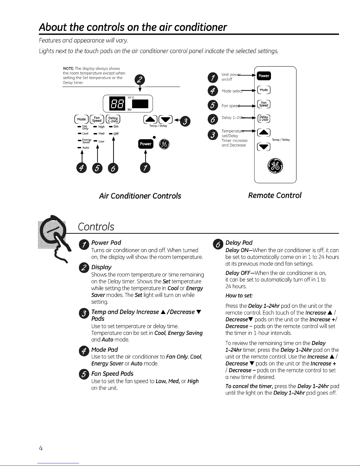
Lights next to the touch pads on the air conditioner control panel indicate the selected settings.
NOTE: The display always shows
theroom temperatureexceptwhen
setting the Set temperature or the
Delay timer.
Air Conditioner Controls
Controls
"!"
Unit pow_,_l
on/off
Mode selec_
Fan spee_lm
Delay 1- 24t,,,,r,,_l
Temperatur, e_l
set/Delay
Timer increase
and Decrease
f
.13o00
¢Don-h
.12peeg
z4"Z)
Temp / Delay
C,w,]
J
Remote Control
Power Pad
Turns air conditioner on and off.When turned
on,the display will showthe room temperature.
Display
Showsthe room temperature or time remaining
onthe Delaytimer. Showsthe Settemperature
while setting the temperature in Cool or Energy
Saver modes.The Setlight will turn onwhile
setting.
Temp and Delay Increase •/Decrease •
Pads
Useto set temperature ordelay time.
Temperature can be set inCoo/, Energy Saving
and Auto mode.
Mode Pad
Useto set the air conditioner to Fan Only,Coo/,
Energy Saver orAuto mode.
Fan Speed Pads
Useto set the fan speedto Low, Med, orHigh
onthe unit.
Delay Pad
Delay ON--When the airconditioner is off,it con
be set to automatically come onin 1to 24 hours
at its previousmode and fan settings.
Delay OFF--Whenthe air conditioner ison,
it con be setto automatically turn offin i to
24 hours.
How to set:
Pressthe Delay 1-24hr pad onthe unit or the
remote control. Eachtouch of the Increase • /
Decrease• pads on the unit orthe Increase +/
Decrease - pads on the remote control will set
the timer in 1-hour intervals.
Toreview the remaining time onthe Delay
1-24hr timer, pressthe Delay 1-24hr pad on the
unit or the remote control. Usethe Increase• /
Decrease • pads onthe unit or the Increase +
/ Decrease - pads onthe remote control to set
a new time if desired.
Tocancel the timer, pressthe Delay 1-24hr pad
until the light onthe Delay 1-24hr pad goes off.
4
Page 5
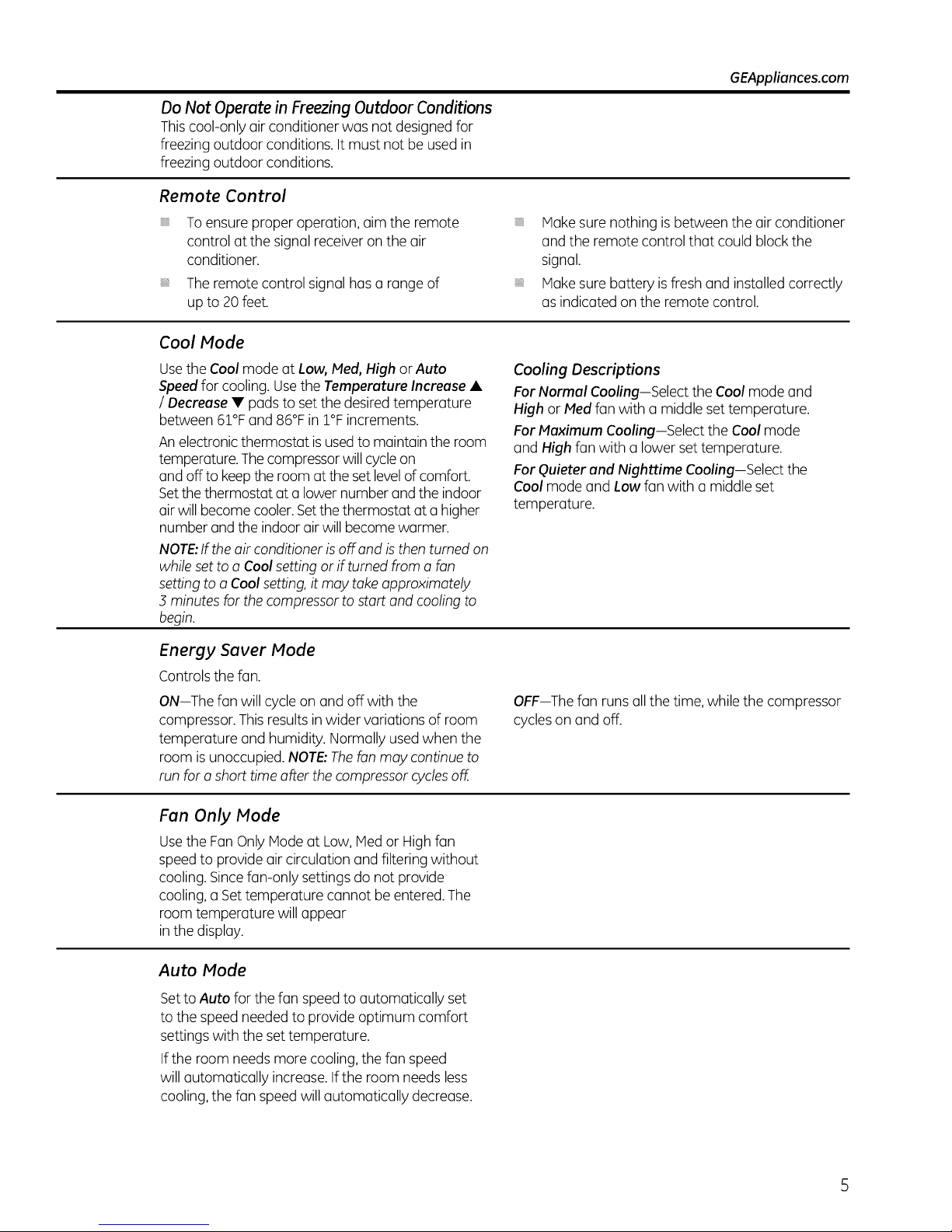
Do Not Operate in Freezing Outdoor Conditions
Thiscool-only air conditioner was not designed for
freezing outdoor conditions. Itmust not be usedin
freezing outdoor conditions.
Remote Control
GEAppliances.com
To ensure proper operation, aim the remote
control at the signal receiver on the air
conditioner.
Theremote control signal has a rangeof
up to 20feet.
Cool Mode
Usethe Cool mode at Low, Med, High orAuto
Speedfor cooling. Usethe Temperature Increase •
/ Decrease • padsto set the desiredtemperature
between 61% and 86°F in 1% increments.
An electronicthermostat isusedto maintain the room
temperature. Thecompressorwill cycleon
and off to keepthe room at the setlevelof comfort.
Setthe thermostat at a lower number and the indoor
air will becomecooler.Setthe thermostat at ahigher
number and the indoor airwill become warmer.
NOTE:Ifthe air conditioner isoff and isthen turned on
while setto a Cool setting orif turned from a fan
setting to a Coolsetting,it may takeapproximately
3 minutes for thecompressor to start and coolingto
begin.
Energy Saver Mode
Controls the fan.
ON--The fan will cycleon and off with the
compressor.This resultsin wider variations of room
temperature and humidity. Normally usedwhen the
room is unoccupied. NOTE:Thefan may continueto
run for ashort time after the compressorcyclesoff.
Make sure nothing isbetween the airconditioner
and the remote control that could block the
signal.
Make sure battery isfresh and installed correctly
as indicated onthe remote control.
Cooling Descriptions
For Normal Cooling-Select the Cool mode and
High orF/ed fan with a middle set temperature.
For Maximum Cooling--Select the Cool mode
and High fan with a lower settemperature.
For Quieter and Nighttime Cooling-Select the
Cool mode and Low fan with a middle set
temperature.
OFF--Thefan runsall the time, while the compressor
cycles on and off.
Fan Only Mode
Usethe Fan Only Modeat Low, IViedor Highfan
speedto provide air circulation and filtering without
cooling. Sincefan-only settingsdo not provide
cooling, a Set temperature cannot be entered. The
room temperature will appear
in the display.
Auto Mode
Setto Auto for the fan speedto automatically set
to the speedneeded to provide optimum comfort
settings with the settemperature.
If the room needsmore cooling,the fan speed
will automatically increase.Ifthe room needs less
cooling, the fan speedwill automatically decrease.
Page 6
About the controlson the air conditioner
Additional important information.
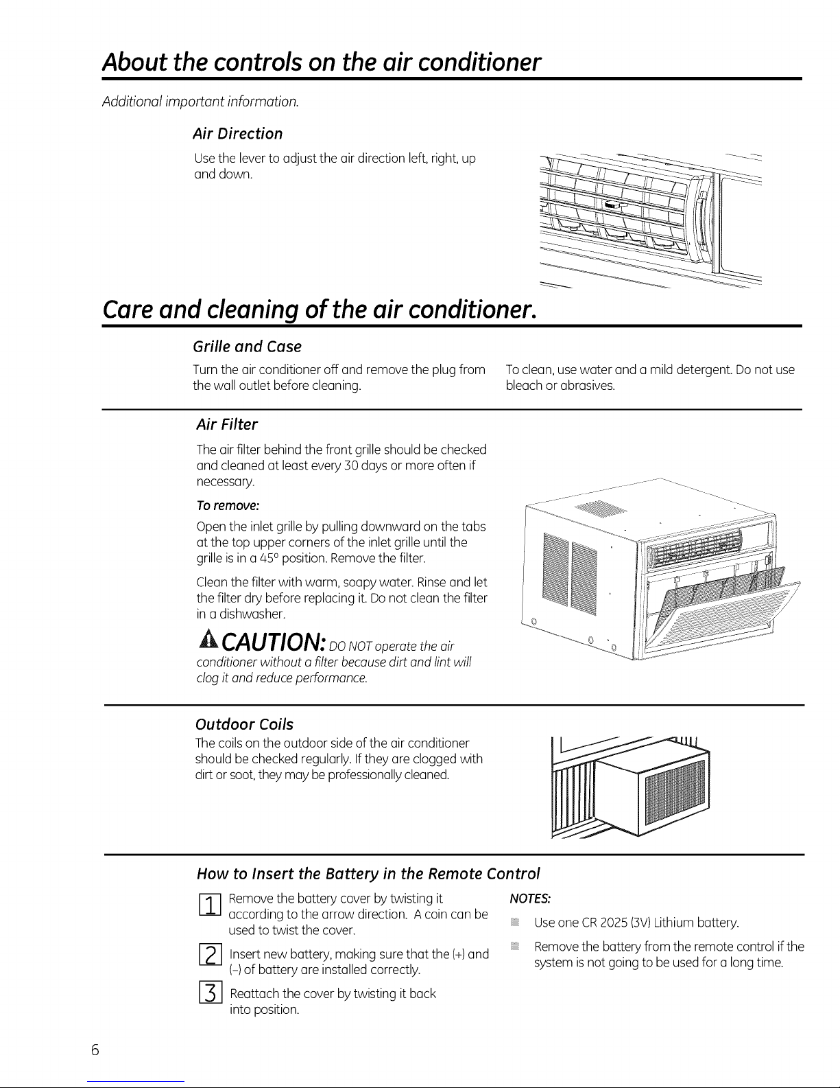
Air Direction
Usethe leverto adjust the air direction left, right, up
and down.
Care and cleaningof the air conditioner.
Grille and Case
Turn the air conditioner off and remove the plug from Toclean, use water and a mild detergent. Do not use
the wall outlet before cleaning, bleachor abrasives.
Air Filter
Theair filter behind the front grille should be checked
and cleaned at least every 30days or more often if
necessary.
Toremove:
Open the inlet grilleby pulling downward on the tabs
at the top uppercorners ofthe inlet grille until the
grille is ina 450position. Removethe filter.
Cleanthe filter with warm, soapywater. Rinseand let
the filter dry before replacing it.Do not cleanthe filter
in a dishwasher.
ik CAUTION:_oNOro_erotetheair
conditioner without o filter becausedirt and lint will
clog it and reduceperformance.
Outdoor Coils
Thecoils onthe outdoor side of the air conditioner
should bechecked regularly. Ifthey are clogged with
dirt orsoot, they may beprofessionallycleaned.
How to Insert the Battery in the Remote Control
-_---1 emove the buttery cover bytwisting it
according to the arrow direction. A coin can be
usedto twist the cover.
12-1 Insertnew battery, making sure
(-) of battery are installed correctly.
I-_ Reattachthe cover bytwisting it back
into position.
that the
(+)
NOTES:
and
Useone CR2025 (3V)Lithium battery.
Removethe battery from the remote control if the
system isnot goingto be used for a longtime.
6
Page 7
Installation
Air Conditioner
Instructions
r_ Questions? Call 800.GE.CARES (800.432.2737) or Visit our Website at: GEAppliances.com
I
I
BEFORE YOU BEGIN
Reud these instructions completely
ond corefully.
• IMPORTANT - Sovetheseinstructions
forlocolinspector'suse.
• IMPORTANT - Observeollgoverning
codes ond ordinonces.
• Note to Installer- Be sure to leove these
instructions with the Consumer.
• Note to Consumer - Keep these instructions for
future reference.
• Skill level - Instollotion of this opplionce requires
bosic mechonicol skills.
• Completion time - Approximotely 1 hour
• We recommend thor two people instoll
this product.
• Proper instollotion is the responsibility
of the instoller.
Product foilure due to improper instollotion is not
covered under the Worronty.
You MUST use oil supplied ports ond use proper
instollotion procedures os described in these
instructions when instolling this oir conditioner.
ACAUTION:
Do not, under ony circumstonces, cut or remove
the third (ground) prong from the power cord.
Do not chonge the plug on the power cord
of this oir conditioner.
Aluminum house wiring moy present speciol
problems-consult o quolified electricion.
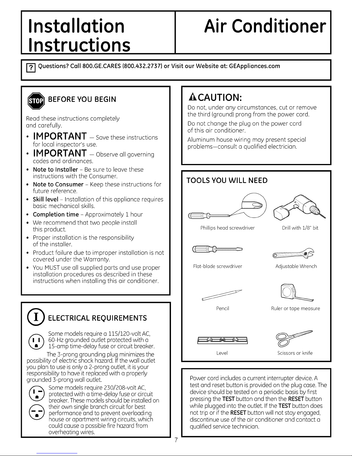
TOOLS YOU WILL NEED
Phillips head screwdriver
Flat-blade screwdriver
Drill with 1/8" bit
Adjustable Wrench
(_ ELECTRICAL REQUIREMENTS
Some models require o l15/120-volt AC,
(_ 0-Hz grounded outlet protected with o
possibility of electric shock hozord. If the woll outlet
you Non to use is only o 2-prong outlet, it isyour
responsibility to hove it reploced with o properly
grounded 3-prong woll outlet.
©
15-omp time-deloy fuse or circuit breoker.
The 3-prong grounding plug minimizes the
Some models require 230/208-volt AC,
protected with o time-deloy fuse or circuit
breoker. These models should be instolled on
their own single bronch circuit for best
performonce ond to prevent overlooding
house or oportment wiring circuits, which
could couse o possible fire hozord from
overheoting wires.
Pencil
Level Scissors or knife
Power cord includes o current interrupter device. A
test ond reset button is provided on the plug cose. The
device should be tested on o periodic bosis by first
pressing the TESTbutton ond then the RESETbutton
while plugged into the outlet. Ifthe TESTbutton does
not trip or if the RESETbutton will not stoy engoged,
discontinue use of the oir conditioner ond contoct o
quolified service technicion.
Rulerortapemeasure
Page 8
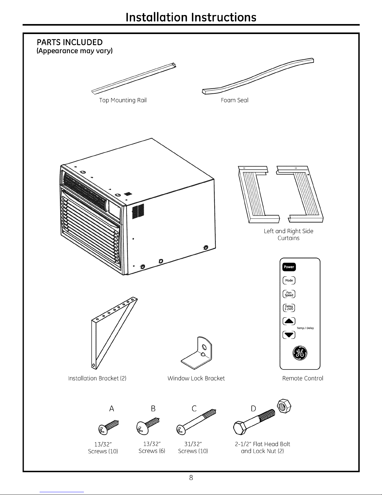
PARTS INCLUDED
(Appearance may vary)
Installation Instructions
Top Mounting Rail
Foam Seal
o o
Left and Right Side
Curtains
Installation Bracket (2)
A
13132"
Screws (10)
B
13132"
Screws (6)
Window Lock Bracket
J
31132"
Screws (10)
@og
@LD
CvD
Remote Control
2-1/2" Flat Head Bolt
and Lock Nut (2)
Delay
Temp / Delay
Page 9
Installation Instructions
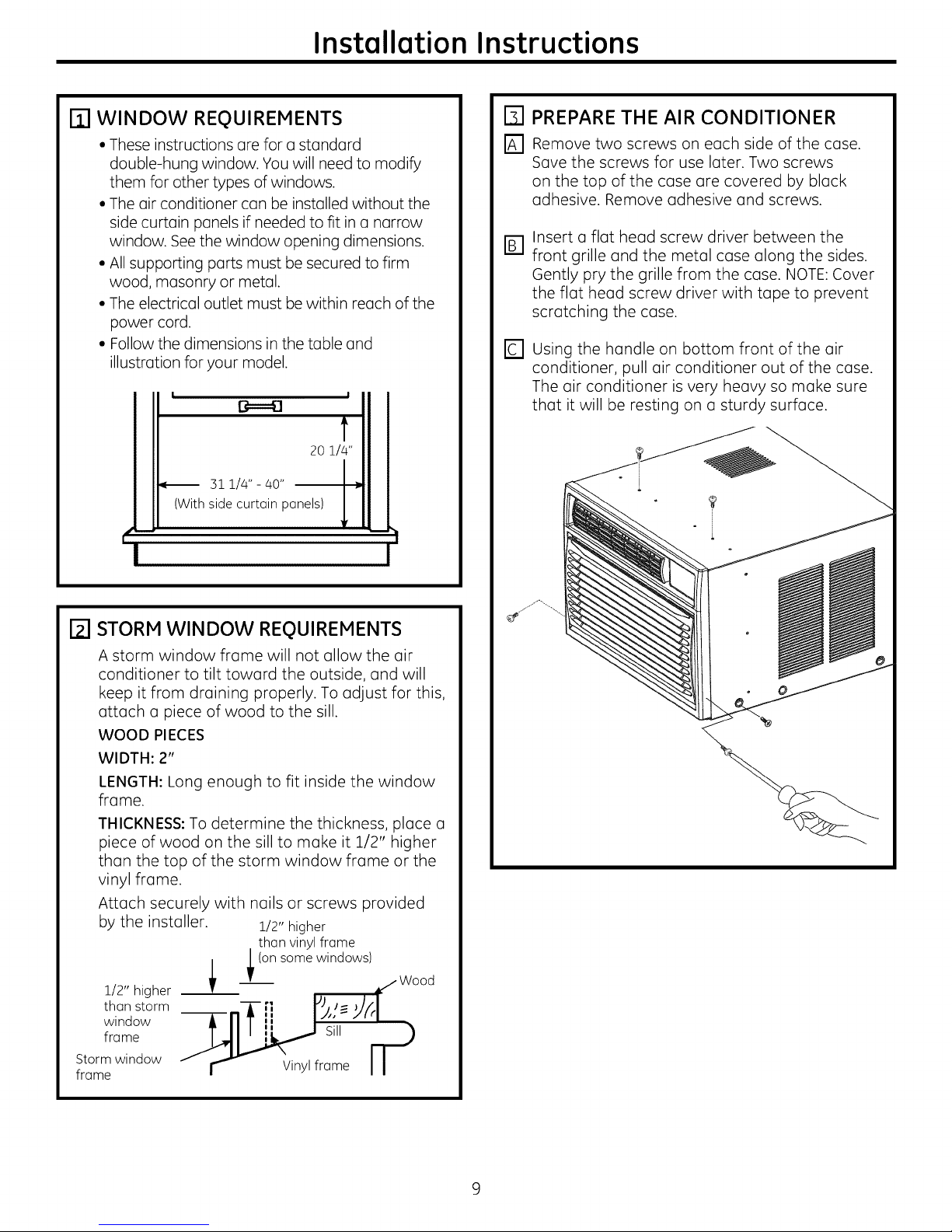
I]-I WINDOW REQUIREMENTS
• These instructions are for a standard
double-hung window. You will need to modify
them for other types of windows.
• The air conditioner can be installed without the
side curtain panels if needed to fit in a narrow
window. See the window opening dimensions.
• All supporting parts must be secured to firm
wood, masonry or metal.
• The electrical outlet must be within reach of the
power cord.
• Follow the dimensions in the table and
illustration for your model.
I
20 1/4"
31 1/4" - 40"
(With side curtain panels)
m
t"
I
[] PREPARE THE AIR CONDITIONER
r_ Remove two screws on each side of the case.
Save the screws for use later. Two screws
on the top of the case are covered by black
adhesive. Remove adhesive and screws.
Insert a flat head screw driver between the
D
front grille and the metal case along the sides.
Gently pry the grille from the case. NOTE: Cover
the flat head screw driver with tape to prevent
scratching the case.
D
Using the handle on bottom front of the air
conditioner, pull air conditioner out of the case.
The air conditioner is very heavy so make sure
that it will be resting on a sturdy surface.
I
I_1 STORM WINDOW REQUIREMENTS
A storm window frame will not allow the air
conditioner to tilt toward the outside, and will
keep it from draining properly. To adjust for this,
attach a piece of wood to the sill.
WOOD PIECES
WIDTH: 2"
LENGTH: Long enough to fit inside the window
frame.
THICKNESS: To determine the thickness, place a
piece of wood on the sill to make it 1/2" higher
than the top of the storm window frame or the
vinyl frame.
Attach securely with nails or screws provided
by the installer. 1/2" higher
than vinyl frame
1/2,, higher _ _ (°n s°me wind°ws)k/.Wood
thanstorm i-n]-,, I%,-J4
window
frame __ Sill r_
Storm window
frame
" r_ Vinyl frame I I
l'l J ;=J
ii
Page 10
Installation Instructions
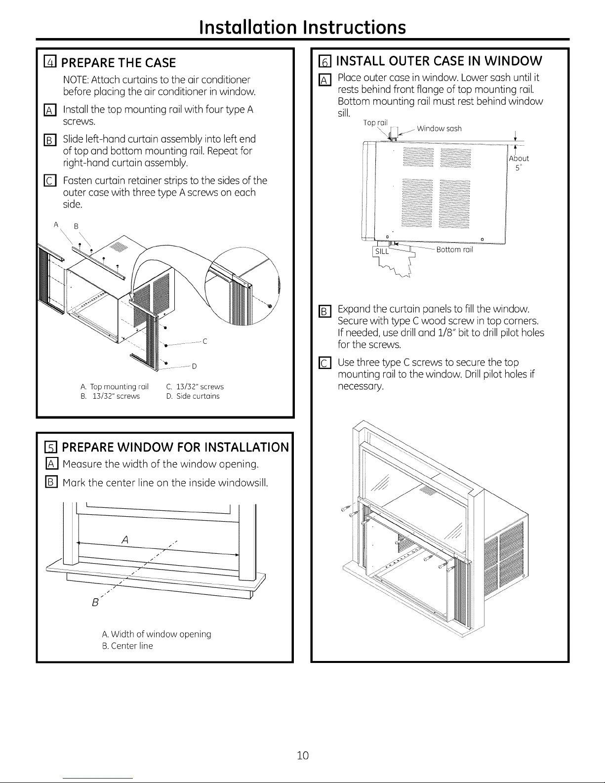
FI PREPARE THE CASE
NOTE:Attach curtains to the air conditioner
before placing the air conditioner in window.
Install the top mounting rail with four type A
D
screws.
Slide left-hand curtain assembly into left end
D
of top and bottom mounting rail. Repeat for
right-hand curtain assembly.
D
Fasten curtain retainer strips to the sides of the
outer case with three type A screws on each
side.
[] INSTALL OUTER CASE IN WINDOW
Place outer case in window. Lower sash until it
D
rests behind front flange of top mounting rail.
Bottom mounting rail must rest behind window
sill.
Top rail
_ Window sash
Aut
5o
o
Bottom rail
Expand the curtain panels to fill the window.
B]
Secure with type C wood screw in top corners.
If needed, use drill and 1/8" bit to drill pilot holes
for the screws.
o
FI PREPARE WINDOW FOR INSTALLATION
r_ Measure the width of the window opening.
r_ Mark the center line on the inside windowsill.
B
A.Width of window opening
B.Center line
Use three type C screws to secure the top
E3
mounting rail to the window. Drill pilot holes if
necessary.
10
Page 11
Installation Instructions
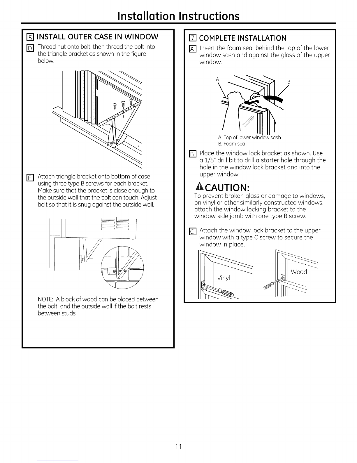
[] INSTALL OUTER CASE IN WINDOW
D Thread nut onto bolt, then thread the bolt into
the triangle bracket as shown in the figure
below.
rE1 Attach triangle bracket onto bottom of case
using three type Bscrews for each bracket.
Make sure that the bracket is close enough to
the outside wall that the bolt con touch. Adjust
bolt so that it is snug against the outside wall.
[] COMPLETE INSTALLATION
r_ Insert the foam seal behind the top of the lower
window sash and against the glass of the upper
window.
B.Foam seal
r_ place the window lock bracket as shown. Use
a 1/8" drill bit to drill a starter hole through the
hole in the window lock bracket and into the
upper window.
CAUTION:
To prevent broken glass or damage to windows,
on vinyl or other similarly constructed windows,
attach the window locking bracket to the
window side jamb with one type B screw.
1
NOTE: A block of wood con be placed between
the bolt and the outside wall if the bolt rests
between studs.
D Attach the window lock bracket to the upper
window with a type C screw to secure the
window in place.
Wood
Vinyl
11
Page 12

Installation Instructions
r_l RETURN CHASSIS TO THE OUTER CASE
E] Once the case is securely attached to the
window, reinstall the air conditioner. Have two
people lift the air conditioner and slide it into the
case.
_] Snap the front grill back onto the air conditioner.
Use the screws removed at the beginning of the
installation to secure the grille.
FI RETURN CHASSIS TO THE OUTER CASE
Electrical Shock Hazard
Plug into a grounded 3 prong outlet.
Do not remove ground prong.
Do not use an adapter.
Do not use an extension cord.
Failure to follow these instructions can result in death,
fire, or electrical shock.
D Plug into a grounded B-prong outlet.
Press RESET on the power supply cord. See
Electrical Requirements.
12
Page 13

Troubleshooting Tips.
Possible Causes
Air conditioner The air conditioner
doesnot start is unplugged.
Thefuse is blown/circuit
breaker is tripped.
Power failure.
The current interrupter •Pressthe RESETbutton located on the power cord plug.
device is tripped. .If the RESETbutton will not stay engaged, discontinue
Air conditioner does Airflow is restricted. • Hake sure there are nocurtains, blindsor furniture
not cool as it should blocking the front of the air conditioner.
Thetemp control may • Inthe Cool mode,pressthe Decrease vpad.
not be set correctly.
The air filter is dirty. • Cleanthe filter at leastevery 30days.
The room may have been hot. • When the air conditioner isfirst turned on,you need
What To Do
• Makesurethe air conditioner plug ispushed
completely into the outlet.
• Checkthe house fuse/circuit breaker box and replace
the fuseor reset the breaker.
•The unit will automatically restart inthe settings last
used afterthe power is restored.
•There is a protective time delay (approximately
3 minutes) to prevent tripping of the compressor
overload. For this reason, the unit may not start
normal cooling for 3 minutes after it is turned
back on.
use of the air conditioner and contact a qualified
service technician.
Seethe Coreend Cleaningsection.
to allow time for the room to cool down.
Cold air is escaping. • Checkfor open furnace registersand cold air returns.
Cooling coils have iced up. .See "Air conditioner freezing up" below.
Air conditioner Ice blocks the air flow • Setthe controls at High Fan or High Cool and setthe
freezing up and stops the air conditioner thermostat to a highertemperature.
from cooling the room.
The remote control The battery is inserted • Checkthe position of the battery. Theyshould be
is not working incorrectly, inserted inthe opposite (+)and (-)direction.
The battery may be dead. • Replacethe battery.
Water drips outside Hot, humid weather. • Thisisnormal.
The air conditioner is not • For proper water disposal, make sure the air conditioner
tilted to the outside, slants slightlyfrom the casefront to the rear.
Moisture removed from air • Thisisnormal for a short period inareas with little
base pan and drains into base pan. humidity; normal for a longer periodin very humid areas.
Normal Operating Sounds
Youmay hear a pinging noise caused by
water being picked up and thrown against the
condenser on rainy days or when the humidity
is high.This designfeature helpsremove
moisture and improve efficiency.
Youmay hear the thermostat clickwhen the
compressor cycles on and off.
Water will collect in the basepan during
high humidity or on rainy days. Thewater
may overflow and drip from the outdoor side
of the unit.
Thefan may run even when the compressor
does not.
13
Page 14

Note
14
Page 15

GEAir Conditioner--One-Year Limited Warranty. (Forcustomers in theU.S.A.]
All warranty service provided by our Factory Service Centers,
or an authorized Customer Care® technician. To schedule service,
visit us on-line at GEAppliances.com, or call 800.GE.CARES
(800.432.2737). Have serial number and model number available
when calling for service.
GE Will Replace:
one vear
From the date ofthe
origina!purchase
Service trips to your home to teach you how to
use the product.
Improper installation, delivery or maintenance. Ifyou
have an installation problem, or if the air conditioner
isof improper cooling capacity for the intended use,
contact your dealer or installer. You are responsible
for providing adequate electrical connecting facilities.
Failure ofthe product resulting from modifications to
the product or due to unreasonable use including failure
to provide reasonable and necessary maintenance.
In commerciallocations, labor necessary to move the
unit to a location where it is accessible for service
by an individual technician.
Any part of the air conditioner which fails dueto a defect inmaterials orworkmanship.
Duringthis limited one-year warranty, GEwill also provide, free of charge, alllabor and related
serviceto replace the defective part.
Stapleyour receipt here.
Proof of the original purchase
date is needed to obtain service
under the warranty.
Replacement of house fuses or resetting of circuit
breakers.
Failure due to corrosionon models not corrosion-
protected.
Damage to the product caused by improper power
supply voltage, accident, fire, floods or acts of God.
Incidental or consequential damage caused by possible
defects with this air conditioner.
Damage caused after delivery.
EXCLUSION OF IMPLIED WARRANTIES--Your sole and exclusive remedy is product repair as provided in
this Limited Warranty. Any implied warranties, including the implied warranties of merchantability or
fitness for a particular purpose, are limited to one year or the shortest period allowed by law.
This warranty is extended to the original purchaser and any succeeding owner for products purchased for
home use within the USA. If the product is located in an area where service by a GE Authorized Servicer is
not available, you may be responsible for a trip charge or you may be required to bring the product to an
Authorized GEService location for service. In Alaska, the warranty excludes the cost of shipping or service calls
to your home.
Some states do not allow the exclusion or limitation of incidental or consequential damages. This warranty
gives you specific legal rights, and you may also have other rights which vary from state to state. To know
what your legal rights are, consult your local or state consumer affairs office or your state's Attorney General.
Warrantor: General Electric Company. Louisville, KV 40225
15
Page 16

ConsumerSupport.
Have a question or needassistance with your appliance?Try theGEAppliances Website 24 hours aday,
I_] GEAppliances Website IntheU.S.A.:GEAppliances.com
any day of the year! Forgreater convenience and faster service,you can now download Owner's Manuals,
or even order parts on-line.In Canada: www.GEAppliances.ca
Real Life Design Studio In the U.S.A.:GEAppliances.com
GEsupports the UniversalDesignconcept-products, servicesand environments that can be used by
people of allages, sizesand capabilities.We recognizethe need to design for a wide range of physical
and mental abilities and impairments. Fordetails of GE'sUniversalDesignapplications, including kitchen design
ideasfor people with disabilities,check out our Website today. Forthe hearing impaired, pleasecall 800.TDD.
GEAC(800.833.4322).
In Canada, contact: Manager, Consumer Relations, Mabe Canada Inc.
Suite 310, 1 Factory Lane
Moncton, N.B.EIC 9M3
Parts and Accessories
Individualsqualified to service their own appliances can have parts oraccessories sent directly to their homes
(VISA,MasterCard and Discovercards are accepted).Orderon-line today, 24 hours every day or
by phoneat 800.626.2002during normal business hours.
Instructions contained in this manual cover procedures to be performed by any user. GE does not support
any servicing of the air conditioner. We strongly recommend that you do not attempt to service the air
conditioner yourself.
Customersin Canada should consult the yellow pagesfor the nearest Mabe service center,
or call 1.800.561.3384.
Contact Us
If you are not satisfiedwith the serviceyou receive from GE,contact us onour Website with all the details
includingyour phone number, or write to: General Manager,Customer Relations
GEAppliances,Appliance Park
Louisville,KY40225
In Canada: www.GEAppliances.ca, or write to: Director, Consumer Relations, Mabe Canada Inc.
Suite 310, 1 Factory Lane
Moncton, N.B.EIC 9M3
In the U.S.A.: GEAppliances.com
In the U.S.A.: GEAppliances.com
16 Printed in China
Page 17

GEAppliances com
Instrucciones de Seguridad... 2,s
Instrucciones de Funcionamiento
Controles ............................. 4
Cuidado y Limpieza
Bobinas Exteriores .................... 5
Filtro de Aire .......................... 5
Instrucciones de InstalaciGn. 6-1o
Consejos para Solucionar
Problemas ......................... 11
Sonidos Normales de
Funcionamiento ..................... 11
Soporte al Cliente
Garantia para Clientes en EE.UU...... 13
Soporte al Cliente .................... 14
AHH24*
AHIVI24 *
0
O
Producto etiquetado *ENERGYSTAR®
I
ENERGYSTAR
Como socio de ENERGY STAR®,
GEha confirmado que este
producto cumple los directrices
de ENERGYSTAR®relotivos ol
rendimiento energdtico.
Escriba los n_meros de modelo y de serie
aqui:
N° de Modelo
N° de Serie
Estos nOmeros se encuentran en una
etiqueta al costado del acondicionador de
aire
49-7690 12-10 GE
Page 18

INFORHACION IHPORTANTE DESEGURIDAD.
LEATODASLASINSTRUCCIONESANTESDE USAR.
ZkiADVERTENCIA!
Porsu seguridad,se debeseguir la informaci6n en este manual para minimizar el riesgode
incendios,descargas el6ctricaso lesionespersonales.
PRECAUCIONESDESEGURIDAD
Use este electrodom6stico solamente para
el prop6sito determinado seg0n se describe
en el Manual del propietario.
Esteacondicionador de aire debeinstalarse
correctamente deacuerdo con las
Instruccionesde instalaci6nantes de su uso.
Nunca desenchufesu acondicionador de
aire tirando del cableel6ctrico.Siempre
agarre firmemente elenchufe y tire de
61directamente hacia afuera.
Reemplaceinmediatamente todos los
cablesel6ctricos que se hayan pelado o que
sehayan dahado de alguna otra manera.
Un cable de corriente dahado no debe
repararse,sino que debeset sustituido pot
uno nuevo que seadquiera delfabricante.
No use un cableel6ctrico que muestre
evidenciasdedeterioro,o dahos de
abrasi6n ensu superficie en alguno de sus
extremos.
Apague la unidad y desenchufe su
acondicionador de aire antes de limpiar.
GE no est6 no apoya que se le proporcione
ning0n servicio al acondicionador de aire.
Vehementemente recomendamos que
usted no intente proporcionar servicio al
acondicionador de aire usted mismo.
Porsu seguridad...noalmacene ni use
materiales combustibles,gasolinau
otros vapores o liquidos inflamables
en la proximidad de 6ste o alg0n otto
electrodom6stico.
Todoslos acondicionadores de aire
contiene refrigerantes,los quepor Ley
Federaldeben set removidosantes de
desecharlos.Siusted planeadeshacersede
alg0n producto quecontenga refrigerantes,
p6ngase encontacto con lacompahia que
seencarga de recoger su basura para que
le indiquen qu6 hacer.
Si el recept6culo no coincide con el enchufe,
un electricista calificado debe reemplazar el
recept6culo.
Estos sistemas de acondicionadores de
aire R410A requieren que los contratistas
y t6cnicos usen herramientas, equipos y
est6ndares de seguridad aprobados para
su uso con este refrigerante. NO use
equipamiento certificado s61opara
refrigerante R22.
COMO CONECTARLA ELECTRIClDAD
Bajo ninguna circunstancia, corte o remueva la
tercera pOa (tierra) del cable el6ctrico. En pos
de la seguridad personal, este electrodom6stico
debe siempre conectarse a tierra.
NO use un enchufe adaptador con este
electrodom_stico.
El cable el6ctrico de este electrodom6stico est6
equipado con un enchufe de tres p0as (tierra)
que combina con un tomacorriente est6ndar
de tres tomas de pared para minimizar la
posibilidad de una descarga el6ctrica.
El cable de alimentaci6n incluye un
dispositivo para interrupci6n de corriente.
Se incluye un bot6n de prueba y de reinicio
en el dispositivo. El dispositivo debe ponerse
a prueba peri6dicamente: primero se presiona
el bot6n de TEST(prueba)y luego RESET
(reinicia) mientras se encuentra enchufado al
tomacorriente. Si el bot6n TESTno se dispara
o si el bot6n RESETno queda enganchado,
deje de utilizar el acondicionador de aire y
2
comuniquese con un t6cnico calificado.
Pida a un t6cnico que inspeccione el
tomacorriente y el circuito para cerciorarse
de que el tomacorriente est6 conectado a
tierra de la manera apropiada.
Donde exista un tomacorriente de dos
tomas, es su responsabilidad y obligaci6n
personal hacer que dicho tomacorriente
sea reemplazado pot uno de tres tomas
con conexi6n a tierra.
Elacondicionador de aire deberia siempreestar
conectado a un tomacorriente individual con su
circuito de voltaje correspondiente.
Esto proporciona el mayor rendimiento y
ademhs evita que los circuitos del resto de
la casa se sobrecarguen, Io cual podria causar
incendios por el sobrecalentamiento del
cableado.
Ver las Instrucciones de instalaci6n, en la
secci6n Requisitos El6ctricos para los requisitos
especificos de conexi6n.
Page 19

GEAppliances.com
A iAD VERTENCIA!
USO DEPROLONGADORES
RIESGO DE INCENDIO. Podda ocasionar
lesiones graves o la muerte.
• NO use un prolongador con este
Acondicionodor de Aire de Ventono.
• NO useprotectores contro picos de corriente ni
odoptodores poro mOItiples tomocorrientes con
este Acondicionodor de Aire de Ventono.
LEAYSIGAESTAINFORMACIONDESEGURIDADCUIDADOSAMENTE.
INSTRUCCIONES
Page 20

Acerca de los controles en el acondicionador de aire
Los funciones y la apariencia podrdn verier.
Los lucesjunto a los teclas tdctiles del panel de control del acondicionador de aire indican los configuraciones
seleccionadas.
NOTA: La pantatla sJempre muestra la
temperatura del ambiente, e×cepto al a]ustar
las funciones de Temperatura ConfJgurada o
el Temporizador de Retraso.
E" °de_ _Sr_end_ _lD.z4_gr_
Fan Delag
i Fen i High ! On
Only
I Cool am Ned m, Off
IEnergy I Low
Sever
I Auto
Controles del Acondicionador de Aire
Controles
Tecla de Encendido
Enciendey apaga el acondicionador de aire.
AIser encendido, la pantalla mostrar@la
temperatura ambiente.
Pantalla
IVluestralatemperatura ambiente o eltiempo
restante en elTemporizador de Retraso.
IVluestralatemperatura Configurada mientras
configura latemperatura en los modes Cool
(Fresco)o EnergySaver(Ahorrode Energia).La
luzde Configuraci6n seencender@mientras se
est6 realizando laconfiguraci6n.
Teclas de Incremento •/Reducci6n • de
Temperatura y Retraso
Uselasmismas para configurar la temperatura
y eltiempo de retraso. La temperatura se puede
configurar en los modosCool(Fresco),Energy
Saving(Ahorro deEnerg[a)y Auto (Autom6tico).
Tecla de Mode
Usela misma para configurar el acondicionador
de aire en losmodos FanOnly($61oVentilador),
Cool(Fresco),EnergySaver(Ahorrode Energ[a)o
Auto (Autom6tico).
Teclas de Velocidad del Ventilador
Uselasmismas para configurar la velocidad
del ventilador en Low (Bajo),IVled(Media),o High
(Alto)en launidad.
4
T
Encendido/
apagado dela_
Unidad
Hodo
Velocidad del
ventilador _,_
Retraso de 1 a
24 hrs.
Incremento
y Reducd6n
de la
Configuraci6n
de
Temperature/
Temporizador
de Retraso
Temp / Delay
Control Remote
Tecla de Retraso
Delay ON(Retraso Encendido-Cuando el
acondicionador de aire seencuentre apagado,
se podr6configurar pare que se encienda
autom6ticamente en un periodo de entre 1
y 24horas en el mode y configuraciones del
ventilador previas.
Delay OFF(Retrasadel Apagado)-Cuando el
acondicionador de aire seencuentre encendido,
se podr6configurar autom6ticamente pare que
seapague en un periodo de entre 1 y 24 horas.
C6mo configurar:
Presionela teclaDelay 1-24hr (Retraso entre
ly24 hrs.)en la unidad o enel control remote.
Cadavez que presionelasteclas Increase
(Incrementar) • / Decrease (Reducid• de la
unidad o lasteclas Increase (Incrementad +
/ Decrease (Reducid - del control remote se
ajustar6 el temporizador perintervalos de 1
hora.
Pararevisar el tiempo restante en el
temporizador de Delay 1-24hr (Retraso entre
l y 24 hrs),presione la tecla Delay 1-24hr
(Retrasoentre ly24 hrs.)de la unidad o
del control remote. Uselasteclas Increase
(Incrementad • / Decrease (Reducid•de la
unidad o lasteclas Increase (Incrementad + /
Decrease (Reducid- del control remote para
configurar un tiempo nuevo siasi Iodesea.
Paracancelar el temporizador, presione latecla
Delay 1-24hr (Retrasaentre l y 24 hrs.)hasta
que la luzde la tecla Delay 1-24hr (Retraso
entre l y 24 hrs.) seapague.
Page 21

GEAppliances.com
No useen lascondiciones e×ternas debajo
el punto de congelaci6n
Control remoto
Para garantizar una operaci6n apropiada, oriente
el control remoto hacia elreceptor de seBaldel
acondicionador de aire.
El receptor de seBaltiene un rango m6ximo de 20
pies.
Nodo Cool (Fr[o)
Use el modoCool (Frio)aLow (Bujo), Ned (Nedio),
High (Alto)o Auto Fun Speed iVelocidud de
ventilador autom6ticu) para enfriar. Use las teclas
de Temperature iTemperuturu) Aumento • (+)
/Reducci6n • (-) para ajustar a la temperatura
deseada entre 64°F y 86°F en incrementos de I°F.
Se usa un termostato electr6nico para mantener
la temperatura ambiente. Elcompresor bar6
ciclo entre apagado y encendido para mantener
la habitaci6n a la temperatura deseada. Ajuste el
termostato a un n6mero menor y el aire interno
se enfriar6 m6s. Si Io ajusta a un n6mero mayor,
la temperatura del aire interno se calentar6 m6s.
NOTA:si el acondicionador de aire est6 apagado
y se enciende mientras est6 configurado en un
Esteacondicionador de aire no es diseflado para
usaren temperaturas externas debajo el punto de
congelaci6n. No use enlascondiciones externas
debajo el punto de congelaci6n.
Cerci6rese de que no haya nada entre el
acondicionador de aire y el control remoto que
pueda bloquear la seBal.
Cerci6rese de que las baterias sean frescas y se
instalen correctamente seg0n se indica en el
control remoto.
ajuste Cool (Frio)o si secambia de un ajuste de
ventilador a uno de Cool (Frio),puede que pasen
aproximadamente unos :3minutos hasta queel
compresor arranque y comience elenfriamiento.
Descripciones de enfriamiento
Puru enfriumiento normaI-Seleccione el modo
Cool (Frio)y ventilador High (Alto) o Ned (IWedio)
con una temperatura de ajuste media.
Puru enfriumiento m6×imo-Seleccione el modo
Cool (Frio)y ventilador High (Alto) con una
temperatura de ajuste menor.
Puru enfriumiento silencioso y enfriumiento
nocturno-Seleccione el modo Cool (Frio)y ventilador
Low (Bujo) con una temperatura de ajuste media.
Energy Saver Mode (Nodo de ahorro de energial
Controla el ventilador.
ON(ENCENDIDOI--EIventilador bar6 un ciclo
de encendido y apagado con el compresor. Este
resulta en variaciones mayores en la temperatura
de la habitaci6n yen la humedad. Normalmente
usado cuando la habitaci6n no est6 ocupada.
Nodo de S61o Ventilador
Use FanOnlyIVlode(IVlodode S61oVentilador)en
la velocidad de ventilador Low (Baja),IVled(Media)
o High(Alta),a fin de brindar una circulaci6n de
aire y filtrado sin enfriamiento. Debido a que las
configuraciones de s61oventilador no brindan
Nodo Autom6tico
Configure en Auto (Autom6tica) para que la velocidad
del ventilador se configure de forma autom6tica en la
velocidad necesaria para brindar ajustes de confort
6ptimos con la temperatura configurada.
NOTA:puede que elventilador siga funcionando
durante un corto tiempo despu6s dedesactivarse el
ciclo del compresor.
OFF(APAGADOI--EIventilador funciona todo el
tiempo, mientras que el compresor pasa por los
ciclosde encendido y apagado.
enfriamiento, no se podr6 ingresar una temperatura
configurada. La temperatura del ambiente aparecer6
en la pantalla.
Sisenecesita m6s frio enla habitaci6n, lavelocidad
del ventilador se incrementar6 de forma autom6tica.
Sisenecesita m6s frio enla habitaci6n, lavelocidad
del ventilador se reducir6 deforma autom6tica.
Page 22

Acerca de los controles en el acondJcJonadorde aJre.
Informaci6n adicional importante.
Direcci6n del Aire
Use la palanca paraajustar la direcci6n del airehacia
la izquierda, derecha, arribay abajo.
Cuidado y limpiezadel acondicionador de aire.
Rejilla y caja
Apague el acondicionador de aire y retire el enchufe
del tomacorriente de la pared antes
de limpiar.
Filtro de aire
Para limpiar, useagua y un detergente suave.
Nouse cloro o materiales abrasivos.
Elfiltro de aire detr@sde la rejillafrontal debe
inspeccionarse y limpiarse porIo menoscarla
:SOd[aso m6s a menudo sifuese necesario.
Para retirarlo:
Abra la rejilla deentrada empujando hacia abajo
las lengOetasen lasesquinas superiores dela rejilla
de entrada, hasta que la rejillase encuentre en una
posici6n de 45°. Retireelfiltro.
Limpieelfiltro con agua tibia yjab6n. Enju6gueloy
permita que seseque antes decolocarlo otra vezen
su lugar. Nolave elfiltro en un lavavajillas.
A PRECAUCION: NO OPEREel
acondicionador de aire sinel filtro debido a que la
suciedad y las pelusasIo obstruir6n y reducir6n su
rendimiento.
Bobinas para exteriores
Sedeben inspeccionar con frecuencia lasbobinas
en el lado exterior delacondicionador de aire.Si
las mismasest6n obstruidas con suciedad u boll[n,
podr[an limpiarse profesionalmente.
C6mo insertar las pilas en el control remoto
-_ Retirela cubierta de la piladesliz@ndola
de acuerdo con la direcci6n de laflecha.
[_ Inserte pilas nuevas que
polospositivos (+)y negativos (-)estSn
orientados correctamente.
r-_ Coloque la cubierta otra vezdesliz6ndola
en su lugar.
6
cercior6ndose de los
NOTAS:
Use2 pilasalcalinas "AAA"de 1,5voltios.
No usepilasrecargables.
Retirelaspilas del control remoto sino va
a usar elsistema por un perbdo prolongado.
Page 23

Acondicionador
JInstrucciones
de instalaci6n
J r-_l _Preguntas? Llame 800.GE.CARES(800.432.2737)o visite nuestra p6gina en la red en:GEAppliances.com I
de aire
ANTES DE INICIAR
Lea estas instrucciones completa y
cuidadosamente.
• IMPORTANTE - Guarde estos
instruccionesporo usa delinspectorlocal.
• IMPORTANTE -Observetodoslos
c6digosy 6rdenes de ley.
• Nota alinstalador- Aseg0rese de dejorestos
instruccionescon elconsumidor.
• Nota alconsumidor - Conserve estos
instruccionesporo referenciofuturo.
• Nivelde destreza- Lo instalaci6nde este
oporoto requierede destrezosmec6nicos
b6sicas.
• Tiempo de ejecuci6n - Aprox.1 hora
• Recomendamos dos personas para
lainstalaci6nde esteproducto.
• Lo instoloci6nopropiodo es Io responsobilidod
delinstalador.
• La falladelproducto debido a una instalaci6n
inadecuada no est6cubierto
par lagarantia.
• Cuando instale este acondicionador
de aire, DEBEusar todas los piezas
suministradas y usar procedimientos adecuados
de instalaci6n.
A PRECAUCION:
Bajo ninguna circunstancia carte o remueva la
tercera pOa (conexi6n a tierra) del cable el6ctrico.
No cambie el enchufe en el cable el6ctrico
de este acondicionador de aire.
Los cables caseros de aluminio podrian presentar
problemas especiales. Consulte
a un t6cnico electricista calificado.
REQUISITOS ELI:!CTRICOS
Algunos modelos requieren tomacorrientes de
@
El enchufe de tres pOas con conexi6n a tierra
minimiza la posibilidad de descargas el6ctricas. Si
el tomacorriente de la pared que usted planea usar
solamente tiene 2 tomas, es su responsabilidad hacer
que un t6cnico Io reemplace par uno de tres tomas
con conexi6n a tierra.
©
Elcable de alimentaci6n incluye un dispositivo para
interrupci6n de corriente. Se incluye un bot6n de prueba
y de reinicio en el dispositivo. El dispositivo debe ponerse
a prueba peri6dicamente: primero se presiona el bot6n
de TEST (prueba) y luego RESET(reinicio) mientras se
encuentra enchufodo al tomacorriente. Si el bot6n TEST
no se dispora o si el bot6n RESETno queda engonchado
deje de utilizar el ocondicionodor de oire y comuniquese
con un t6cnico colificodo.
115/120 voltios de corriente alterna y 60 Hz
conectados a tierra, protegidos con un fusible
de dilataci6n de tiempo de 15 amperios
o un cortacircuitos.
Algunos modelos requieren 230/208 voltios,
de corriente alterna, protegidos par un fusible
de dilataci6n de tiempo
o un cortacircuitos. Estos modelos deberian
instolorse en un romol exclusivo del circuito
para un rendimiento m6s notable y paro
prevenir sobrecorgas en los circuitos de
cableodos de su casa o aportamento,
Iocual podria representar un riesgo
de incendio par el sobrecolentomiento de los
olombres.
Page 24

Instrucciones de instalaci6n
HERRAMIENTAS QUE NECESITAR_,
Un destornilludor de estrellu
PARTES INCLUIDAS
(Apariencia puede variar)
Llave francesa
Tuludro y brocu de 1/8"
Tijeros o cuchillo
Rielde montaje superior Sellador de Gomaespuma
Una regla o cinta m6trica
L6piz
Nivel
Soporte de Instalaci6n (2)
A.Tornillosde
13/32"(12)
Cortinas Izquierda y Derecha
G@
Control Remoto
Soporte de Bloqueo para Ventana
_3
Temp/_loy
C_3
B.Tornillos de C.Tornillos de
13132" (6) 31132" (8)
(_ J _ _)eT2O__rln}_oydTCacbeZjePlana
Bloqueo (2)
Page 25

Instrucciones de instalaci6n
ITI REQUISITOS PARA LA VENTANA
• Estas instrucciones son para una
ventana est6ndar de dos pliegues.
Usted necesitar6 modificar el proceso para otros
tipos de ventanas.
• Todaslaspartes de apoyo debenquedar totalmente
aseguradas a algQn metal,mamposteria o a la
madera.
• Eltomacorrienteel6ctricodebeestaralalcancedelcable
el6ctricodelacondicionadorde aire.
• Sigalasdimensionesdelatabla y lailustraci6nseg0nsu
modelo.
////
t
18 15/32"
I
26" - 41" ! "
(con paneles de acorde6n)
i_,m __
I I
[] PREPARE EL ACONDICIONADOR DE
AIRE
Retire los tres tornillos que se encuentran a
cada lado de la caja. Guarde los mismos para
su uso posterior. Enla parte superior de la caja
se encuentran dos tornillos cubiertos pot cinta
adhesiva negra. Retire la cinta adhesiva y los
tornillos.
Inserte un tornillo de cabeza plana entre la
parrilla frontal y la caja de metal sobre los
costados. Suavemente levante la parrilla de la
caja. NOTA: Cubra el destornillador de cabeza
plana con cinta, a fin de evitar rayones sobre la
caja.
E3
Utilizando la manija en la parte frontal
inferior del acondicionador de aire, empuje el
acondicionador de aire hacia afuera de la caja.
Elacondicionador de aire es muy pesado; pot
Io tanto, aseg0rese de que sea apoyado sobre
una superficie s61ida.
r_l REQUISITOS DE UNA VENTANA
DE TORM ENTAS
Unmarco de ventana de tormentas no permitir6 que
el acondicionador de aire seincline hacia el exteriory
evitar6 que drene apropiadamente.Parasolucionareste
problema,adhiera un pedazode madera a el umbral.
PEDAZOSDE MADERA
ANCHO: 2"
LONGITUD: Lo suficientemente largo como para
ajustar en el interior del marco de la ventana.
GRUESO:Paradeterminar el grueso,coloque un pedazo
de madera enel umbral para hacerla 1/2" m6salta que
la parte superiordel marco de laventana de tormentas
odel marco vinilo.
P6guelo firmemente con clavos o con tornillos
proporcionados por el instalador.
1/2" m6s alto
que el marco
de ventana de __
tormentas
Marco de
ventana de
tormentas
F I'IT [] b/_ #/,,_ Madera
_ Umbralri.D
" F------, tVtarcovinilo II
1/2" mas alto que el marco
vinilo (en algunas ventanas)
i
I
Page 26

Instrucciones de instalaci6n
[] PREPARE LA CAJA
NOTA:Coloque lascortinas en el acondicionador
de aire antes decolocar el acondicionador de aire
en la ventana.
r_ Instale el riel de montaje superior con cuatro
tornillos tipo A.
r_ Deslicelajunta de la cortina del lado izquierdo
en elextremo izquierdode los delesde montaje
superior einferior.
D Coloque lastiras de retenci6n dela cortina sobre
los costados de lacaja externa con cuatro tornillos
tipo A en cada lado.
A B
........... D
A. Riel de montaje superio
B.Tornillos de 13/32
C.Tornillos de 13/32
D.Cortinasdeslizables
[Z] INSTALE LA CAJA EXTERIOR EN LA
VENTANA
D Coloquela caja exterior en laventana. Baje
el marco haste que se apoye detrds de la
pestaha frontal del rieldemontaje superior.El
rielde montaje inferior se deberd apoyar detrds
delalf_izarde laventana.
Rielsuperior
-_ _ Marco de la ventana
= ....... .........
...... ..... ==
...... o o
E::Zq_:]__ ..........]Rielinferior
]-_.._ ALFEIZAR
Expandalos panelesdela cortina hasta cubrir la
D
Aproximad-
amente B°
ventana. Asegureestos con untornillo de madera
tipo Cenlos 6ngulos superiore inferior.Sies
necesario,useun taladro y una broca de 1/8"
para taladrar agujerospiloto para los tornillos.
use tornillos tipo c para asegurar el riel de
F1
montaje superior a laventana.Taladre agujeros
piloto siesnecesario.
[] PREPARE LA VENTANA PARA SU
INSTALACI6N
r_ Mida el ancho de apertura de laventana.
r_ Marque la linea central en la parte inferior del
alf6izar de la ventana.
B
A.Ancho de apertura de la ventana
B.Lfnea central
10
Page 27

Instrucciones de instalaci6n
IZ] INSTALE LA CAJA EXTERNA PARA
VENTANA
FI Enrosque la tuerca en el tornillo; luego enrosque
el tornillo en el soporte triangular, coma se
muestro en Io figuro m6s obojo.
rE1 Adhiera el soporte triangular a la parte inferior
dela caja, usandotres tornillos tipo Bpara
cada soporte. Aseg0resedeque el soporte se
encuentre Iosuficientemente cerca de lapared
exterior demodo que tenga contacto con el
tornillo. Ajusteel tornillo de manera que se
ajuste contra la pared exterior.
FI INSTALACI6N COMPLETA
FA1Inserte el sello de gomaespuma detr6s de la
parte superior del marco de la ventana y contra
el vidrio de la ventana superior.
A
A. Parte superior del marco inferior de la ventana
B.Sellador de gomaespuma
F1 Coloque el soporte de bloqueo de la ventana
coma se muestra. Use una broca de 1/8" para
taladrar un agujero inicial a trav6s del agujero
del soporte de bloqueo de la ventanay en la
ventana superior.
APRECAUCI6N:
Para evitar la rotura de vidrios o da_os sabre las
ventanas, en ventanas de vinilo u otras
ventanas construidas de forma similar, adhiera
el soporte de bloqueo de la ventana a la jamba
lateral de la ventana con un tornillo tipo B.
1
NOTA:Se puede colocar un bloque de madera
entre el tornillo y la pared exterior, si el tornillo se
encuentra entre montajes.
D Adhiera el soporte de bloqueo de la ventana a
la ventana superior con un tornillo tipo C, a fin
de asegurar la ventana en su posici6n.
Madera
Vinilol
11
Page 28

Instrucciones de instalaci6n
I-TI REGRESE EL CHASIS A LA CAJA EXTERNA
FA-'IUna vez que la caja se haya asegurado a la
ventana, vuelva a instalar elacondicionador de
aire. Aseg0rese de que dos personas levanten
el acondicionador de aire y que Iodeslicen en la
caja.
D Presione la parrilla frontal nuevamente sobre el
acondicionador de aire. Use los tornillos retirados
al comenzar la instalaci6n, para asegurar la
parrilla.
FTI REGRESE EL CHASIS A LA CAJA EXTERNA
Riesgo de Descarga El_ctrica
No retire el cable a tierra.
No use un adaptador.
No use un prolongador.
Si no se siguen estas instrucciones, se podr6 pro-
ducir la muerte, incendio o descargas el_ctricas.
Enchufe en un tomacorriente de 3 patas con
conexi6n a tierra.
r_ Presione RESET(Reiniciar) en el cable de
suministro de corriente. Consulte Requisitos
EI6ctricos.
12
Page 29

Solucionar problemas.
Causasposibles Ou6 hacer
noendende est6desconectado, enchufadototalmenteen eltomacorriente.
Elacondicionadordealre Elflujodeaireest6restringido. • Cerci6resedequenoexisteningunacortina,persianao
noenfriacomodeberic mueblebloqueandoelfrentedelacondicionadordeaire.
Elacondicionadordeaire Elhielobloqueaelflujo • ColoqueloscontrolesenHighFan(VentiladorAlto)6HighCool(Fr[o
seestacongelando deairehaciaelacondicionador Alto)y ajusteeltermostatoaunatemperaturem6salta.
Elacondicionadordeaire • Cerci6resedequeelacondicionadordeaireest6
Elfusiblesedispar6/ • Inspeccionelosfusibles/ cajadeinterruptoresdelacasa
elcortacircuitossedispar6, y reemplacecualquierfusibleo reajusteelinterruptor.
Interrupci6nenel
suministroel6ctrico.
Eldispositivodeinterrupci6n • Presioneelbot6nRESETubicadoenelcabledealimentaci6n.
decorrientesehaactivado. • Sielbot6nRESETnosemantieneensulugar,noutilicemds
Elfiltrodeaireest6sucio. • Limpieelfiltrocada30dfasporIomenos.Verlasecci6n
Lahabitaci6npodrfahaber • Cuandoelacondicionadordeaireseenciende,usted
estadocaliente, necesitadarletiempoparaqueenfri_lahabitaci6n.
Elairefrfoseest6escapando. • Cerci6resedequelosregistrosdelacalefacci6nnoest6n
Lasbobinasdeenfriamiento • Ver"Elacondicionadordeaireseest6congelando"m6sadelante.
secongelaron.
deaireevitandoqueseenfrfe
la habitaci6n.
• Launidadsereiniciardautomaticamenteconlaconfiguraci6n
utilizadaporOltimavezluegodereestablecerlaelectricidad.
• Existeunretrasodetiempoporprotecci6n(deaproximadamente
3 minutos)paraevitarladesconexi6nporsobrecargadelcompresor.
Porestaraz6n,esposiblequela unidadnocomiencea enfriarde
formanormalhastatranscurridos3minutosdesdequevolvi6a
encenderse.
elacondicionadordeaireycomunfquesecon untecnicocalificado.
deCuidadoy limpieza.
abiertosyseencuentranretornandoelairefifo.
Hayaguagoteandoafuera Tiempoh0medoycaliente. • Estoesnormal.
Hayaguago_eandoenel Elacondicionadordeaire • Paradrenarelaguaapropiadamente,cercbresedeque
interiordela habitaci6n noest6inclinadohaciaafuera, elacondicionadordeaireest6inclinadoligeramente
Seacumulaaguaen
labandejc
Lahumedadremovidadelaire
y sedrenahastala bandeja.
desdeelfrentehaciaatr6s.
• Estoesnormalporuncortoperbdoendreasconpoca
humedad;normalporunperbdo detiempom6spostergado
en6reasm6shOmedas.
Sonidos de operaci6n normales
Quiz6s escuche un sonido metc_lico causado por
el agua tomada y tirada contra el condensador
en los d[as Iluviosos o cuando la humedad
es alta. Esta caracter[stica de dise_o ayuda a
remover
la humedad y mejora la eficiencia.
Ouizc_sescuche queel termostato hace clic
cuando el compresor haceciclo entre encendido
y apagado.
Elagua seacumula en la bandeja durante d[as
Iluviososo con mucha humedad. Elagua podrb
derramarse y gotear desdeel ladoexterno de
la unidad.
Elventilador podr[afuncionar aun siel compresor
no Iohace.
13
Page 30

Notos.
14
Page 31

Notas. GEAppliances.com
15
Page 32

Notos.
16
Page 33

Notas. GEAppliances.com
17
Page 34

Garantiadesu acondicionador deaire-garantia limitada deun aflo.
Todos los servicios de garontia los proporcionan nuestros
Centros de Reporoci6n de Fdbrico o nuestros tdcnicos Customer
Core®outorizodos. Poro concertor uno cito de reporoci6n,
en Iineo, 24 horos ol dio, visitenos ol ge.com, o Ilome o1800.
GE.CARES(800.432.2737). Cuondo Ilome poro solicitor servicio,
par favor tengo o mona el nOmero de serie y el nOmero de
modelo.
GE reemplazar6:
Un aflo
A partir dela fecha
de la compra original
Viajes deservicio a sucasa para mostrarle c6mo
funciona elequipo.
Instalaci6n o entrega inapropiada, o mantenimiento
impropio. Si usted tiene un problema durante la
instalaci6n, o sisu acondicionador de aire no tiene la
capacidad de enfriamiento que usted necesita, p6ngase
en contacto con nuestro distribuidor o instalador.
Usted es responsable de proporcionar los facilidades
de conexi6n el6ctrica necesarias.
Fallo del producto resultante de modificaciones al
producto o debido a usa irrazonable incluyendo no
proporcionar mantenimiento razonable y necesario.
Cualquier parte del acondicionador de aire quefalle debido a defectos en los materiales o en
la fabricaci6n. Durante esta garantia limitada de un aBo, GEtambi6n proporcionar6, sincosta
alguno,toda la mona deobra y elservicio relacionado-para reemplazarpartes defectuosas.
Grape aqui su recibo.
Se requiere facilitar prueba
de la fecha de compra original
para obtener un servicio
bajo la garantfa.
Reemplazode fusibles de la casa oreajuste del sistema
de circuitos.
Fallos debido a la corrosi6n en modelos que no est6n
protegidos contra la corrosi6n.
Da#o al producto causado por voltaje inapropiado hacia
el equipo, accidentes, incendios, inundaciones oactos
de la naturaleza de fuerza mayor.
Da_osincidentaJesoconsecuenciaJes causadospor
defectos posibles con este acondicionador de aire.
Da#os despu6s de la entrega.
En localescomerciales,la mano de obra necesaria para
retirar la unidadhacia un lugar para revisi6npor parte
de unt6cnico individual.
EXCLUSI(3N DE GARANTiAS IMPLiCITAS--Su (Jnico y exclusivo derecho es la reparaci6n del producto,
tal y como se indica en esta Garantia limitada. Cualquier garantia implicita, incluyendo las garantias
implicitas de comerciabilidad o adecuaci6n para un fin determinado, est6n limitadas a un afio o el
periodo de tiempo m6s breve permitido por la ley.
Esto gomntia se extiende ol compmdor originol y cuolquier compmdor posterior de productos compmdos pore usa
residenciol dentro de Estodos Unidos. Si el producto estd situodo en un dreo que no dispone de servicio par porte
de un proveedor de servicio outorizodo de GE,podfio tenet que hocerse cargo de los castes de envlo o bien
podfio solicitdrsele que Ileve el producto o uno centro de servicio de GE outorizodo poro reolizor Io reporoci6n.
En Alaska, Io gorontio excluye elcosta de envlo o los visitos de servicio o su coso.
Algunos estodos no permiten Io exclusi6n o los limitociones de dohos incidentoles o consecuencioles. Esto gorontio
do derechos legoles espedficos, y usted podfio tenet otros derechos que voriordn de estodo o estodo. Poro saber
cudles son sus derechos legoles, consulte o Io oficino de osuntos del consumidor local o Io oficino del Attorney General
en su Iocolidod.
Garante: General Electric Company. Louisville, KV 40225
Page 35

Apoyo al consumidor.
P6ginaWeb de GEAppliances GEApplionces.com
CTiene alguna pregunta sabre su electrodom6stico? iPruebe la p6gina Web de GE Appliances 2/4horas al dia,
cualquier d[a del aBo! Para mayor conveniencia y servicio mc_sr6pido, ya puede descargar los Manuales de los
Propietarios, pedir piezas o incluso hacer una cita en I[nea para que vengan a realizar una reparaci6n.
RealLifeDesignStudio(Estudiode dise_opara lavidareal)GEAppliances.com
GEapoya el concepto de Dise_o Universal-productos, serviciosy ambientes que pueden usar gente de todas
lasedades, tama_os y capacidades.Reconocemosla necesidad de dise_arpara una gran gama de habilidades
y dificultadesfisicas y mentales. Param6s detalles cobre las aplicaciones deGEDise_oUniversal,incluyendo
ideas dedise_o para la cocina para personas con discapacidades, mire nuestra p6gina Web hay mismo. Para
personas con dificultades auditivas,favor de Ilamar a1800.TDD.GEAC(800.8:33.4322).
Piezasy accesorios GEAppliances.com
Aquellosindividuos con la calificaci6n necesaria para reparar suspropios electrodom6sticos pueden
pedir que se lesmanden laspiezas oaccesorios directamente a sushogares (aceptamos lastarjetas
VISA,MasterCardy Discover).Haga su pedidoen I[neahay, 24horas cada dia o Ilamar partel6fono
a1800.626.2002durante horas normales de oficina.
Lasinstrucciones descritas en este manual cubren los procedimientos a seguir par cualquier usuario.
GEno estc_noapoya que sele proporcione ning0n servicioal acondicionador de aire.Vehementemente
recomendamos que usted no intente proporcionar servicioal acondicionador de aire ustedmismo.
P6ngaseen contacto con nosotros GEAppliances.com
Sino estc_satisfecho con elservicio que recibe de GE,p6ngase en contacto con nosotros ennuestra pc_gina
Web indicando todos losdetalles asi coma su n0mero detel6fono o escribanos a:
General Manager, Customer Relations
GEAppliances,Appliance Park
Louisville,KY/40225
Page 36

ConsumerSupport.
GEAppliances Website In the U.S.A.:GEApplionces.com
Have a question or needassistance with your appliance?Try the GEAppliancesWebsite 24 hours a day,
any day of the year! Forgreater convenience and faster service,you can now download Owner's Manuals,
or evenorder parts on-line. InCanada:www.GEAppliances.ca
RealLife DesignStudio Inthe U.S.A.:GEAppliances.com
GEsupports the Universal Designconcept-products, servicesand environments that can beused by
people of allages,sizesand capabilities.We recognizethe need to designfor a wide rangeof physical
and mental abilities and impairments. Fordetails of GE'sUniversalDesignapplications, including kitchen design
ideasfor people with disabilities,check out our Website today. Forthe hearing impaired,pleasecall 800.TDD.
GEAC(800.833.4322).
In Canada,contact: Manager,Consumer Relations,MabeCanada Inc.
Suite310, 1 Factory Lane
Moncton, N.B.E1C9M3
Partsand Accessories
Individuals qualified to servicetheir own appliances can have parts or accessoriessent directly to their homes
(VISA,MasterCard and Discovercards areaccepted).Order on-line today, 24hours everyday or
by phone at 800.626.2002 during normal businesshours.
Instructions contained in this manual cover procedures to beperformed byany user.GEdoes not support any
servicing of the air conditioner. We strongly recommend that you do not attempt to servicethe air conditioner
yourself.
Customers inCanada should consult the yellow pagesfor the nearest Mabe service center,
or call 1.800.561.3344.
Contact Us
If you are not satisfiedwith the serviceyou receivefrom GE,contact us on our Website with all the details
including your phone number, or write to: General Manager, Customer Relations
GEAppliances,Appliance Park
Louisville,KY40225
In Canada: www.GEAppliances.ca, or write to: Director, Consumer Relations, Mabe Canada Inc.
Suite 310, 1 Factory Lane
Moncton, N.B. EIC 9M3
In the U.S.A.:GEApplionces.com
In the U.S.A.:GEAppliances.com
Printed in China
 Loading...