

Page 1
GE Consumer & Industrial
TECHNICAL SERVICE GUIDE
Portable Room Air Conditioner
MODEL SERIES:
APN08
APN10
APH10
PUB # 31-9126 11/04
Page 2

IMPORTANT SAFETY NOTICE
The information in this service guide is intended for use by
individuals possessing adequate backgrounds of electrical,
electronic, and mechanical experience. Any attempt to repair a
major appliance may result in personal injury and property
damage. The manufacturer or seller cannot be responsible for the
interpretation of this information, nor can it assume any liability in
connection with its use.
WARNING
To avoid personal injury, disconnect power before servicing
this product. If electrical power is required for diagnosis or test
purposes, disconnect the power immediately after performing the
necessary checks.
RECONNECT ALL GROUNDING DEVICES
If grounding wires, screws, straps, clips, nuts, or washers used to
complete a path to ground are removed for service, they must be
returned to their original position and properly fastened.
GE Consumer & Industrial
Technical Service Guide
Copyright © 2004
All rights reserved. This service guide may not be reproduced in whole or in part
in any form without written permission from the General Electric Company.
– 2 –
Page 3

TABLE OF CONTENTS
Air Filter ................................................................................................................................ 7
Circulation Pump ................................................................................................................ 18
Components ........................................................................................................................11
Component Locator Views ................................................................................................. 10
Compressor ....................................................................................................................... 15
Condenser Fan Assembly .................................................................................................. 17
Control Features .................................................................................................................. 8
Control Panel ......................................................................................................................11
Drainage .............................................................................................................................. 7
Evaporator Fan Assembly .................................................................................................. 16
Factory Test Mode ............................................................................................................. 21
Filter Drier ......................................................................................................................... 20
Illustrated Parts List ...........................................................................................................23
Installation Information ......................................................................................................... 7
Introduction .......................................................................................................................... 4
Key Function Chart ............................................................................................................ 21
Louver Motor and Louvers .................................................................................................18
Nomenclature ....................................................................................................................... 5
Operation/Smart Board .......................................................................................................11
Outer Cover ........................................................................................................................11
Power Supply Board .......................................................................................................... 12
Schematics and Wiring Diagrams ...................................................................................... 22
Technical Data ..................................................................................................................... 6
Thermistors ........................................................................................................................ 14
Warranty .............................................................................................................................26
– 3 –
Page 4
Introduction
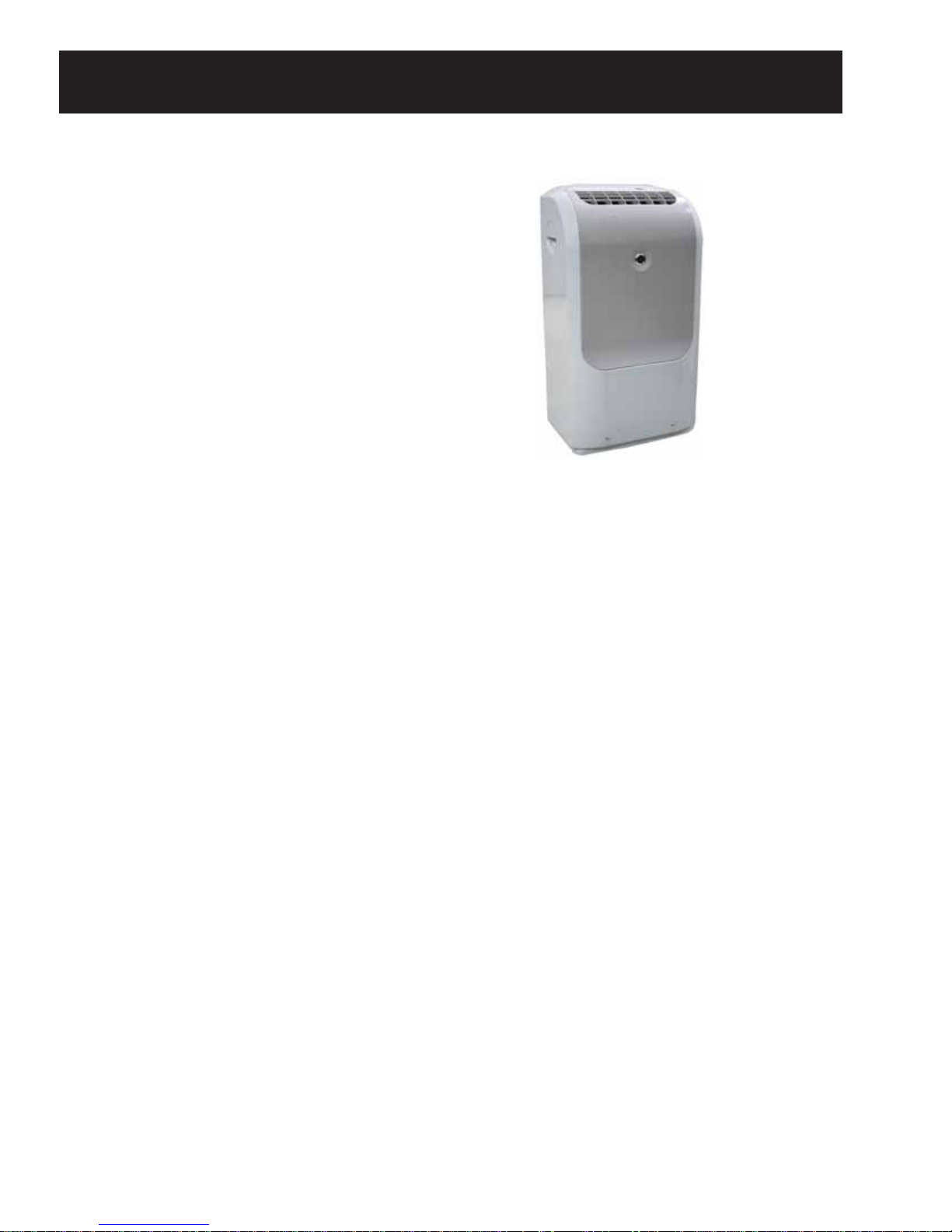
The new Portable Room Air Conditioner can be easily
moved from room to room with minimal set-up time. It
utilizes a water pump system that uses stored condensate
to effi ciently cool the condenser, helping to dissipate heat
quickly and reduce operating costs.
Features:
• 4.0 Dehumidifi cation (pints/hr).
• Electronic thermostat.
• 24-hour delay.
• 3 cooling / 3 fan only speeds.
• Available with 8,000 or 10,000 BTUH (cooling).
• The DRY MODE provides dehumidifi cation only.
• The power outage recovery feature automatically restarts the unit in the last settings used after the
power is restored.
– 4 –
Page 5
Model Number
Brand
A=GE
Product Type
P=Portable
Supplier
K=Medea
N= Kelon
P=Kelon
Capacity
Nominal BTU’s
in 1000’s
Nomenclature
A P N 10 A A G 1
Engineering
Revision
Compressor
T=Toshiba
G=Goldstar
Commercial Change
A=Original
Voltage 60Hz
L=115V < 7.0 Amps
A=115V > 7.5 Amps
F=115V 7.0 - 7.5 Amps
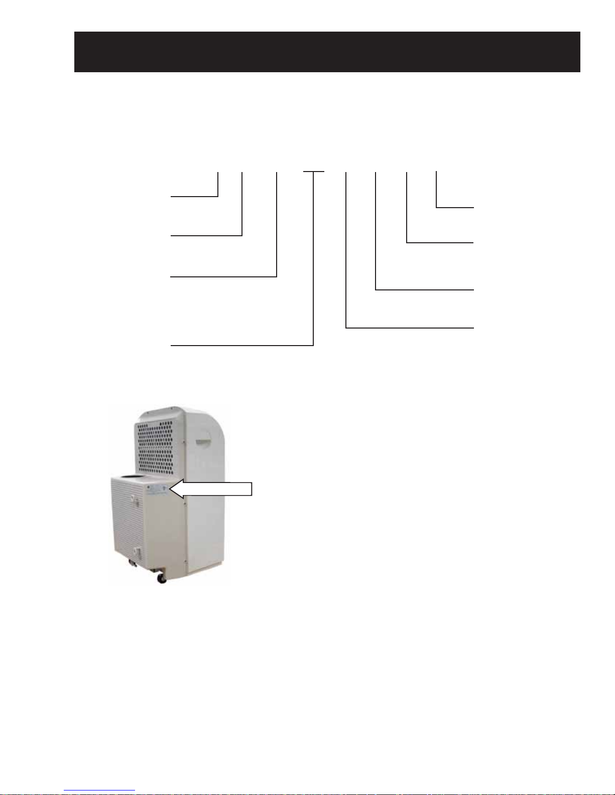
Nomenclature
The mini-manual is located under the
front cover. The nomenclature tag is
located on the left side of the unit. It
contains important information such as:
• Model/serial number
• Refrigerant charge
• Voltage rating
• Cool amperes
• BTU/h
R
Serial Number
The fi rst two characters of the serial number
identify the month and year of manufacture.
Example: AG123456 = January, 2004
A - JAN 2005 - H
D - FEB 2004 - G
F - MAR 2003 - F
G - APR 2002 - D
H - MAY 2001 - A
L - JUN 2000 - Z
M - JUL 1999 - V
R - AUG 1998 - T
S - SEP 1997 - S
T - OCT 1996 - R
V - NOV 1995 - M
Z - DEC 1994 - L
The letter designating
the year repeats every
12 years.
Example:
T - 1974
T - 1986
T - 1998
– 5 –
Page 6
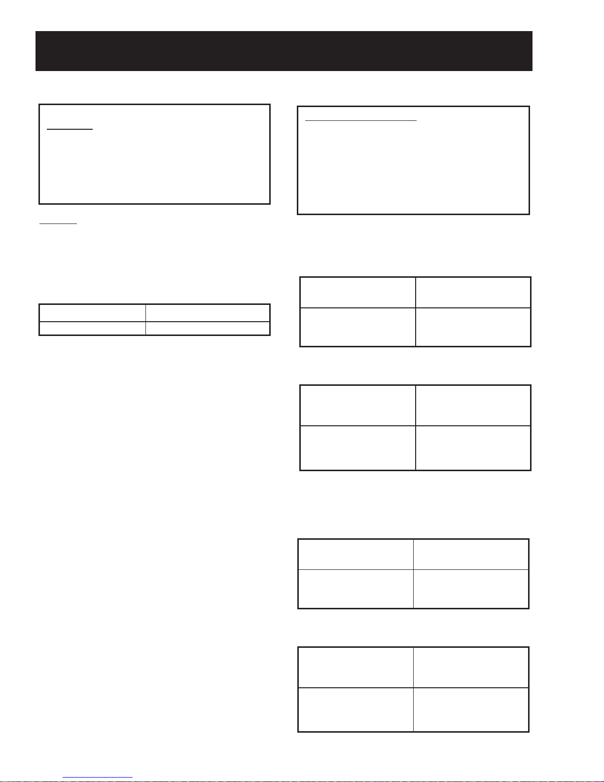
Technical Data
A
T
T
A
DISC ONNE CT POWER B EF OR E SE R VICING
IMPOR TAN
T - RECONNECT ALL GROUNDING DEVICES
ll parts of this appliance capable of conducting
electrical current are grounded. If grounding wires,
screws, straps, nuts or washers used to
complete a path to ground are removed for service,
they must be returned to their original position and
properly fastened.
WAR NING
DISCONNECT UNIT FROM ELECTRICAL POWER SUPPLY
BEFORE MAKING ANY ELECTRICAL CHECKS.
MAX IMUM C UR R E NT LEA K AG E : 0.5 MILLIAMP
MAX IMUM G R OUN D PATH R E S IS TANC E : 0.1 OHM
POWER SUPPLY
RATEDVOLTAGE VOLTAGE LIMITS
115 103-
REPLACEMENT PARTS
D SCRIPTION CAT.NOE
IRFILTER
COMPRESSOR
CONDENSER FAN
EVAPORATOR FAN
COMPRESSOR CAPACITOR
FAN CAPACITOR
TRANSFORMER
POWER CNTRL ASM
WATER PUMP SWITCH
POWER SUPPLY PCB
CONDENSER FAN MTR
EVAPORATOR MTR
LOUVER MTR
WATER PUMP MTR
PCB BRD OPERATION
CAPILLARY TUBE 22” LONG
CONDENSER ASM
127
WJ85X10126
WJ98X10172
WJ94X10204
WJ87X10154
WJ20X10123
WJ73X10135
WJ01X10243
WJ26X10199
WJ26X10201
WJ26X10200
WJ94X10205
WJ87X10153
WJ95X10010
WJ95X10011
WJ26X10197
WJ53X0188
WJ88X10143
IMPORTANT SAFETY NOTICE
This information is intended for use by individuals
possessing adequate backgrounds of electrical,
electronic and mechanical experience. Any attempt
to repair a major appliance may result in personal
injury and properly damage. The manufacturer or
seller cannot be responsible for the interpretation of
this information, nor can it assume any liability in
connection with its use.
APN08AAG1
CURRENT-TEMPERATURE CHECK DATA
AIR TEMPERATURE COOLING CURRENT
CONDENSER IN ˚F MIN. MAX.
70 7.3 7.6
80 8.7 9.2
EMPERATURE DIFFERENTIAL CHECK DATA
EVAPORATOR EVAP AIR TEMP
AIR TEMP IN OUT ˚F
˚F
N. MAX.MI
70 42 48
80 49 55
90 61 6
APN10AAG1, APH10AAG1
CURRENT-TEMPERATURE CHECK DATA
AIR TEMPERATURE COOLING CURRENT
CONDENSER IN ˚F MIN. MAX.
70 8.2 8.7
80 9.3 9.8
6
– 6 –
EMPERATURE DIFFERENTIAL CHECK DATA
EVAPORATOR EVAP AIR TEMP
AIR TEMP IN OUT ˚F
˚F
N. MAX. MI
70 42 48
80 50 56
90 60 6
5
Page 7
Drain cap
Air filter
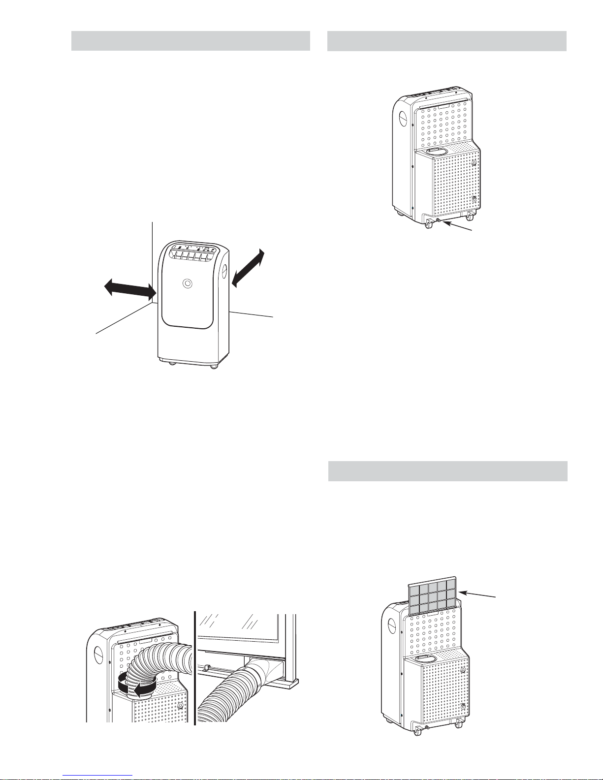
Installation Information
Back of unit
Drainage
• The air conditioner should be placed on a
smooth and level fl oor strong enough to
support the unit.
• Place the unit in an area where the
temperature will not fall below 65°F (18°C).
The coils can become covered with frost at
temperatures below 65°F (18°C), which may
reduce performance.
• Allow at least 12 inches (30 cm) of airspace
on all sides of the unit for good air circulation.
12 in. (30 cm )
12 in. (30 cm)
min.
min.
The drain cap is located at the bottom back of the
unit.
The unit is designed to automatically evaporate
water collected in normal settings. However, in
very humid settings, the unit may occasionally
need to be drained.
If the WATER FULL indicator light is blinking
and the unit is still operating, it has reached the
maximum water collection level and should be
drained. If the light stays on and the unit shuts
off, the unit will need to be drained before it will
operate again.
Note: The portable air conditioner has rollers
to aid placement, but should only be rolled on
smooth and level surfaces. Do not attempt to
roll the portable air conditioner on carpet or over
objects.
• To ensure proper cooling, do not kink or pinch
the duct. An excessive number of bends in the
exhaust hose may compromise the cooling
performance.
• To attach the exhaust hose to the back of the
air conditioner, push it into the exhaust outlet
and twist.
The unit should be drained if it is not going to
be run for an extended period of time. The unit
should also be drained prior to storage at the end
of the cooling season.
Air Filter
The air fi lter is located on the back of the air
conditioner. It should be checked and cleaned at
least every 30 days, or more often if necessary.
To remove air fi lter, grasp the tab and gently
pull the fi lter up and out. Wash it in warm soapy
water.
– 7 –
Page 8
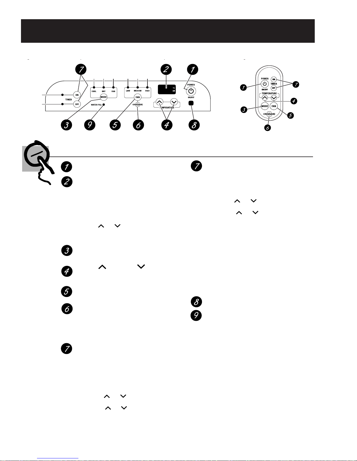
Control Features
gp p g
Cool
Dry
Fan
Low
Medium
Mode
Mode
Mode
Timer On
Timer Off
On
On
Fan
On
On
High
Fan
Fan
On
On
Air Conditioner Control Remote Control
Controls
ON/OFF Pad
Turns the air conditioner on and off.
Display
Shows the room temperature. Also shows the
set temperature while setting the temperature
in COOL mode or the set time while setting
TIMER ON or TIMER OFF.
NOTE: The display will change to show the
room temperature after settings have been
made. To recall the set cooling temperature,
press the or pad. To recall the timer
setting, press the TIMER ON pad or the TIMER
OFF pad for the timer that is set.
MODE
Use to set the air conditioner to COOL, DRY
or FAN mode.
Increase /Decrease Pads
Use to set temperature when in COOL mode
or to set a time with the timer feature.
FAN Pad
Use to set the fan speed to LOW, MEDIUM or HIGH.
CIRCULAIRE
Turn on to provide continuous side-to-side
air circulation.
For fixed side-to-side air direction, turn on
until the desired air direction is obtained,
then turn it off.
TIMER Pad
ON—The air conditioner can be set to
automatically come on in 1/2 (0.5) to 24 hours
at its previous setting. The unit must be on
while setting TIMER ON.
1. Press the POWER (ON/OFF) pad.
2. Press the TIMER ON pad. The TIMER ON
light will blink.
3. Press the or pad to set the desired
time for the unit to start. (Each time you
touch the or pads, the set time will
advance by 30 minutes between 0 and 10 hours
and by one hour between 10 and 24 hours.)
4. Press the TIMER ON pad again to start the timer.
5. Press the POWER (ON/OFF) pad to turn the
unit off.
TIMER Pad (cont.)
OFF—When the air conditioner is on, it can
be set to automatically turn off in 1/2 (0.5)
to 24 hours.
1. Press the TIMER OFF pad. The TIMER OFF
light will blink.
2. Press the or pad to set the desired
time for the unit to stop. (Each time you
touch the or pads, the set time will
advance by 30 minutes between 0 and 10
hours and by one hour between 10 and 24
hours.)
3. Press the TIMER OFF pad again to start
the timer.
After settings have been made, the display will
change back to show the room temperature.
NOTE: Both timers may be set, in combination,
to turn the unit on and off as desired.
To cancel the timer, press and hold the TIMER
ON or TIMER OFF pad (depending on the
timer(s) set) until its indicator light goes off.
Remote Control Signal Receiver
Water Full Indicator Light
When the Water Full Indicator Light begins
blinking, the unit has reached maximum
water collection level.
If water level does not lower in 40 minutes,
the unit will power off and it must be
manually drained.
1. Unplug the power cord and roll the unit
to a drain or outside.
2. Pull out the drain cap from the back
bottom edge and allow water to drain
from the unit.
3. Replace the drain cap and put the unit
back into operation.
NOTE: The unit is designed to automatically
evaporate water collected in normal settings.
However, in very humid settings, the unit may
occasionally need to be drained.
– 8 –
Page 9

– 9 –
Page 10

Component Locator Views
Front View
Louver Motor
Rear View
Vent Cover
Evaporator
Evaporator Fan
Evaporator Thermistor
Power Supply Board Cover
Condenser
Accumulator and Compressor
Condenser Fan
Water Switches
Power Supply Housing Shown with Cover Removed
Power Supply Board
Evaporator Fan Motor Capacitor
Condenser Fan Motor Capacitor
Water Pump
Drain
12V Transformer
Compressor Run Capacitor
– 10 –
Page 11

Components
Outer Cover
The outer cover must be removed to access the
internal components of the air conditioner. The
cover separates into 2 sections. It is held in place
by 8 Phillips-head screws, 2 on top and 3 on
each side.
Control Panel
The control panel is held in place by 8 tabs on
the inside of the outer cover. The outer cover
must be removed to access the tabs. (See Outer
Cover). Depress the tabs inward to remove the
control panel.
Operation/Smart Board
The operation/smart board is located behind the
control panel.
The operation/smart board is held in place by
9 Phillips-head screws. The outer cover must
be removed to access the screws. (See
Cover.)
Troubleshooting the operation/smart board:
If the unit is dead (no functions or indicators on
display):
• Check for 120 VAC on the power supply board
from the blue wire at CN8 (neutral) to the
brown wire on relay RLY1 (L1). If 120 VAC is
not present, check for an open in the wiring
from the power supply board to the terminal
block or the power cord.
• If 120 VAC is present between CN8 and
RLY1, check for 120 VAC at CN12 (primary
of low voltage transformer). If 120 VAC is not
present, replace the power supply board.
Outer
Note: If the brown wire is on the wrong terminal of
RLY1, the low voltage transformer will not receive
voltage.
• If 120 VAC is present at CN12, check for
12 VAC on the power supply board
at CN17. If 12 VAC is not present,
replace the low voltage transformer.
If 12 VAC is present at CN17, check
for 12 VDC at CN19, pin #1 and #5.
If voltage is not present, replace the
power supply board. If 12 VDC is
present, replace the operation/smart
board.
– 11 –
1
5
CN19
Page 12

Power Supply Board
The power supply board is located in the power supply housing behind the outer cover next to the
evaporator fan. The power supply housing cover is held in place by 7 Phillips-head screws.
Caution: Lock tabs on all low voltage wire connectors on the power supply board and operation/smart
board are fragile. Tab breakage can occur if excessive release pressure is applied.
Power Supply Board (PSB) Connector Locator
1 - Low water level switch (CN10) - 5 VDC should be measured across the two white wires in the white
connector when the low level switch is open.
2 - High water level switch (CN9) - 5 VDC should be measured across the two red wires in the white
connector when the high level switch is open.
Note: If CN9 and CN10 are reversed, the compressor will shut off after water trips the pump switch
(approximately 60 seconds). The condenser fan will continue to run for approximately 40 minutes.
3 - Thermistors (CN1). Pins #1 and #2 are the room ambient thermistor. Pins #3 and #4 are the
evaporator thermistor. The display will default to 75 F with an open connector. Output from the
board is 5 VDC between pin #1 and #2 and also between pin #3 and #4 with the connector
unplugged.
4 - Louver motor (CN5). Motor is approximately 200 Ω, 8 VDC should be measured between pin #1
and #5.
5 - CN19 to operation/smart board (CN15). CN19 is permanently attached to the PSB. 12 VDC should
be present between pin #1 and #5.
6 - CN14 to operation/smart board (CN20). CN14 is permanently attached to the PSB.
7 - Water pump (CN13 and CN2).
8 - Compressor capacitor (CN7).
9 - Terminal block (CN8 neutral).
10 - Transformer (CN12 primary). 120 VAC output from board to primary. Primary transformer
resistance is approximately 125 Ω.
– 12 –
Page 13

11 - Evaporator fan motor (CN3). Approximate resistance readings:
WH to BK - 70 Ω
WH to G - 90 Ω
WH to Y - 105 Ω
12 - Condenser fan motor (CN4). Approximate resistance readings:
WH to BK - 45 Ω
WH to Y - 80 Ω
13 - Transformer (CN17 secondary). Secondary transformer input 12 VAC. Secondary transformer
resistance is approximately 2 Ω.
14 - Compressor overload.
15 - Terminal block (L1). L1 input from the power cord.
6
5
1 2
3
4
13
– 13 –
7
12
15
11
14
7
9
8
10
Page 14

Thermistors
The air conditioner has 2 thermistors that come
as one assembly. The thermistor assembly part #
is WJ27X10065.
To check the thermistors for an open or short, run
the Factory Test Mode (see
The room temperature thermistor is located on
the front of the evaporator and positioned in place
by a plastic retainer.
Thermistor
Factory Test Mode).
The evaporator thermistor is located on the right
side of the evaporator in a copper sleeve.
Thermistor
Copper Sleeve
Check for resistance of the room temperature
thermistor at CN1 on the power supply board
between pin 1 and pin 2. Resistance will be
approximately 18 kΩ at 70°F.
Thermistor Resistance Chart
Temperature °FTemperature °CResistance
(kΩ)
10 -12 96.7
30 -1 53.4
32 0 50.7
50 10 30.6
70 21 18
90 32 11
Check for resistance of the evaporator thermistor
at CN1 between pin #3 and pin #4 on the power
supply board. Resistance will be approximately
18 kΩ at 70°F (21°C).
– 14 –
Page 15

Compressor
Check for 120 VAC on the power supply board
at RLY1 between CN7 and the black wire when
COOL or DRY is selected.
Compressor resistance values:
Common to Start = 2.1 Ω
C
Common to Run = 0.7 Ω
Compressor Run Capacitor
The run capacitor is located behind the power
supply board cover. The capacitor has a value of
50 µfd.
Start to Run = 2.8 Ω
If the air conditioner is shut off and immediately
started again during the COOL or DRY mode,
it will take approximately 3 minutes for the
compressor to restart.
To direct start the compressor with the overcool
and compressor protection disabled, enter the
factory test mode (see
select COOL or DRY on the control panel.
Note: The factory test mode cannot be entered
if the unit has shut down due to high water (see
Float Switch Operation). Unplug the unit and drain
the sump before entering factory test mode.
Compressor Wiring Direct Check
WARNING: Check windings fi rst. If open or
grounded, DO NOT apply power to compressor
terminals.
Factory Test Mode) and
R
S
Run Capacitor Check
1. Replace the run capacitor with a known good
test capacitor and attempt to start compressor.
Note: Test capacitor can be 10 µfd higher than
originally specifi ed for the unit.
2. If the compressor starts, install a new run
capacitor with correct rating specifi ed for the
unit.
Brown
– 15 –
Page 16

Evaporator Fan Assembly
The evaporator fan assembly consists of a
3-speed, 120 VAC motor and fan. It is connected
to the power supply board at CN3.
Resistance Check
Disconnect CN3 and check for resistance on the
motor connector between the following wires:
• White to black wires (high speed) approximately 70 Ω.
• White to green wires (medium speed) approximately 90 Ω.
• White to yellow wires (low speed) approximately 105 Ω.
ACN (White, Neutral)
7. Remove the 5 Phillips-head screws that hold
the power suppy housing in place. Remove
the power supply housing.
Blank Pin
INFH (Black, High Speed)
INFM (Green, Medium Speed)
INFL (Yellow, Low Speed)
CN3
Evaporator Fan Assembly Removal:
1. Remove the outer cover (see Outer Cover).
2. Remove the ground wire.
3. Remove the plastic wire ties on the left and
right side of the vent cover.
4. Remove the power supply housing cover (see
Power Supply Board).
8. Remove the 7 Phillips-head screws (3 on
each side and 1 in the middle) that hold the
vent cover in place. Remove the vent cover.
Vent Cover ScrewsScrews
5. Disconnect the associated wiring from the
power supply board and the evaporator fan
capacitor.
6. Remove the evaporator thermistor from the
evaporator.
– 16 –
Page 17

9. Remove the 8 Phillips-head screws from each
side of the evaporator fan housing. Remove
the evaporator fan housing.
Evaporator Fan Housing
Evaporator Fan
The fan is held in place by a 10-mm retaining
nut. The fan motor is held in place by 3 Phillipshead screws.
Condenser Fan Motor Removal
1. Remove outer cover (see Outer Cover).
2. Remove the power supply housing cover (see
Power Supply Board).
3. Disconnect the motor wires from the power
supply board. Remove the ground wire.
4. Remove the 7 Phillips-head screws from
the condenser fan housing. Separate the
condenser fan housing.
Condenser Fan Housing
Retaining Nut
Condenser Fan Assembly
The condenser fan assembly consists of a
2-speed 120 VAC motor and fan. It is connected
to the power supply board at CN4.
Disconnect CN4 and check for resistance on the
motor connector between the following wires:
• White to black wires (high speed) approximately 45 Ω.
• White to yellow wires (low speed) approximately 80 Ω.
Condenser Fan
The fan is held in place by an 8-mm hex-head
set screw. The fan motor is held in place by 4
Phillips-head screws.
Set Screw
– 17 –
Page 18

Louver Motor and Louvers
Circulation Pump
The louver motor is a 12-VDC motor that
moves the louvers from side to side when
the CIRCULAIRE button is pressed on the
control panel. The louver motor is connected
to the power supply board at CN5 and has an
approximate resistance of 200 Ω.
Louver Motor
Check for approximately 8 VDC between pin #1
and pin #5 with the wire harness disconnected.
CN5
1
5
Note: The power supply board will interrupt full
motor voltage for 1.5 seconds to allow for motor
reversing.
To access the louver motor, separate the outer
cover (see Outer Cover). The louver motor is held
in place by 2 Phillips-head screws.
The circulation pump is located next to the
compressor. It is connected to the power supply
board at CN13 and CN2. It has a supply voltage
of 120 VAC and a resistance of 29 Ω.
Circulation Pump
The circulation pump circulates the condensate
water from the sump to the sprinkler through
a plastic hose. The sprinkler distributes the
condensate water on the condenser fi ns for
evaporation. Condensate water that is not
evaporated returns to the sump for recirculation
to the sprinkler.
Sprinkler
To remove the louvers, use a small fl at-bladed
screwdriver to lift the holding bracket past the
lock tabs.
Drive Louver
Screws
Holding Bracket
Lock Tabs
Note: The louvers and louver linkage can be
replaced separately. The drive louver must be
ordered separately, it is not interchangeable with
the remaining 5 louvers.
Water Flow
Sump
– 18 –
Page 19

Circulation Pump Float Switches
There are 2 fl oat-operated switches in the
condensate water circulation system. The lowlevel switch, CN10, controls the pump. The highlevel switch, CN9, acts as a safety to prevent
fl ooding.
Low-Water-Level Switch
High-Water-Level
Switch
Float Switch Operation
When the drain sump is empty, both switches
are open. When the water level rises, the lowlevel switch closes and starts the pump. When
the water level drops, the switch opens and the
pump stops. At higher water levels, the low-level
switch stays closed and the circulation pump runs
continuously. If the low-level switch stays closed
for longer than 15 minutes, the condenser fan,
normally operating at high speed during COOL,
will change to low speed.
If the water level continues to rise, the highlevel switch closes and:
• After 1 minute, the WATER FULL indicator
light fl ashes.
• The compressor and evaporator fan shut
down.
• The condenser fan operates at high speed.
• The circulation pump continues to run.
If the high level switch stays closed for 40
minutes, the unit beeps twice and:
• The condenser fan and circulation pump shut
off.
• The WATER FULL indicator light stays on,
and all other indicator lights on the control
board turn off.
• The unit displays the room temperature.
Note: The low and high level switches must be
open and the unit must be manually drained and
restarted to resume operation.
WARNING: If condenser air fl ow is restricted,
condensate in the sump may become hot.
If the sump overfl ows and the pump is not
running:
• Check for 120 VAC between CN13 and CN2
on the power supply board. If voltage is
present, replace the pump.
• If 120 VAC is not present between CN13 and
CN2, check for 5 VDC at CN10. If 5 VDC is
not present, replace the board.
• If 5 VDC is present, check continuity of the
low-level switch at CN10 on the power supply
board.
• If the switch is open, check for an inoperative
fl oat or defective switch.
• If the unit has not shut down after 40 to 45
minutes during high condensate levels, check
for continuity of the high-level switch at CN9.
If the switch is open, check for an inoperative
fl oat or defective switch. If the unit still fails to
shut down, replace the board.
– 19 –
Page 20

Filter Drier
The fi lter drier should be installed anytime the
sealed system is repaired.
Caution: Brazing heat can cause the mastic to
become sticky and/or catch fi re. Remove the
mastic BEFORE installing the drier and charging
valve.
Replace the mastic after installation to help
deaden sound and reduce rattles.
Charging Valve
Mastic
Filter Drier
Parts
Charging Valve - Part # WJ56X61
Mastic - Part # WR2X9363
Drier - Part # WJ56X10003
– 20 –
Page 21

Factory Test Mode
The air conditioner has a factory mode function that allows the service technician to test various
functions.
Note: The factory test mode cannot be entered if the unit has shut down due to high water (see Float
Switch Operation under
Circulation Pump). Unplug the unit and drain the sump before entering factory
test mode.
• To enter the factory test mode, unplug the unit, then plug it back in while simultaneously pressing
and holding the ON button.
• While the ON button is still pressed, the software checks the 2 thermistors for open/short conditions.
If the thermistor is open, the power supply board beeps. After this initial test, all the functions can
then be tested. (Overcool protection and compressor protection are disabled on the compressor.)
• To exit the factory test mode, unplug the unit.
Key Function Chart
Function Key -
Electronic Mode
On/Off On
On/Off Off Nothing displayed Unit unpowered
Temperature Button
Fan Speed Button
Mode Button
Timer Button On
Timer Button Off Nothing Displayed N / A
Energy Saver On / Off On
Energy Saver On / Off Off
Circulaire
Sleep Mode
Status /
Function
Increase /
Decrease
Desired Room
Temperature
Increase /
decrease
Desired Fan
Speed
Changes
unit function
between Fan
Only and Cool
Mode
Engages
motorized
air discharge
louvres
Button activates
Sleep Mode
Display Action Notes
Appropriate symbol of Fan
or Cool and Temperature
Cool Symbol and Desired
Temperature
Fan Symbol or LED and
Desired Fan Speed (F1, F2
& F3 or Low, Med & High)
Appropriate symbol of Fan
or Cool or LED
Timer symbol or LED On
with time count (1 - 12 or 1
- 24 hrs.)
Energy Saver Symbol (or
LED) and Temperature
Standard mode and function
symbol
May have a Circulaire
symbol or LED display
Sleep symbol (or LED)
displayed for 15 seconds
after key is depressed
Unit powered up, compressor
On / fan On. When restarted,
the compressor will stay off for 3
minutes
Desired air temperature is set
& discharged from unit. Fan
and compressor cycle until set
temperature is received by temp
sensor.
Desired fan speed (RPM) is set &
fan motor speed changes
In Cool Mode, the unit fan and
compressor run and cool air is
discharged from unit. In Fan Mode,
the compressor is OFF and fan
runs at set speed to circulate
ambient temperature air in room.
Time Function is set.
In this mode the fan runs at
a reduced RPM when the
compressor shuts off. When the
compressor restarts, the fan RPMs
change back to the desired setting.
Standard Cool Cycle mode and
function
Motorized louvres begin auto swing
sequence
Unit runs for 8-hour cycle when
sleep key is pressed. One hour
after, cycle start temperature
increases a minimum 2°F to a
maximum of 4°F from the set point
for the duration of the cycle.
Temperature is not displayed in
Fan Mode.
In Fan Only mode, fan symbol
and speed will stay on display. In
Cool Mode, fan speed will briefl y
appear on display then display will
revert to temperature setting.
Time Function can be set so that
the unit can be made to run or
shut down with timer.
– 21 –
Page 22

Schematics and Wiring Diagrams
1L
N
– 22 –
Page 23

Illustrated Parts List
– 23 –
Page 24

VIEW DESCRIPTION QUANTITY APN08AAG1 APN10AAG1 APH10AAG1
0001 REMOTE CONTROL 1 WJ26X10204 WJ26X10204 WJ26X10204
0002 FRONT PANEL ACCESS 1 WJ90X10085 WJ90X10085 WJ90X10085
0003 PCB BRD OPERATION 1 WJ26X10197 WJ26X10197 WJ26X10197
0004 SUPPORT PANEL PCB 1 WJ26X10198 WJ26X10198 WJ26X10198
0005 POWER CNTRL ASM 1 WJ26X10199 WJ26X10199 WJ26X10199
0006 FRONT CVR 1 WJ90X10086 WJ90X10086 WJ90X10086
0007 MNTG CLIP 2 WJ01X10241 WJ01X10241 WJ01X10241
0008 EVAPORATOR MTR 1 WJ87X10153 WJ87X10153 WJ87X10153
0010 EVAPORATOR FAN 1 WJ87X10154 WJ87X10154 WJ87X10154
0013 LOUVER MTR 1 WJ95X10010 WJ95X10010 WJ95X10010
0014 LINKAGE ROD/LVR MTR 2 WJ85X10123 WJ85X10123 WJ85X10123
0015 VERTICAL LVR A 5 WJ85X10124 WJ85X10124 WJ85X10124
0016 VERTICAL LVR B 1 WJ85X10125 WJ85X10125 WJ85X10125
0017 LINKAGE ROD 1 WJ27X10064 WJ27X10064 WJ27X10064
0018 CAVITY 1 WJ01X10242 WJ01X10242 WJ01X10242
0019 AIR OUTLET 1 WJ76X10191 WJ76X10191 WJ76X10191
0020 EVAPORATOR ASM 1 WJ87X10155 WJ87X10155 WJ87X10155
0022 POWER SUPPLY PCB 1 WJ26X10200 WJ26X10200 WJ26X10200
0023 FAN CAPACITOR 2 WJ73X10135 WJ73X10135 WJ73X10135
0024 COMPRESSOR CAPACITOR 1 WJ20X10124 WJ20X10123 WJ20X10123
0025 TRANSFORMER 1 WJ01X10243 WJ01X10243 WJ01X10243
0027 CONDENSER ASSEMBLY 1 WJ88X10145 WJ88X10143 WJ88X10143
0028 SPRINKLER 1 WJ75X10002 WJ75X10001 WJ75X10001
0030 AIR TUNNEL COND 1 WJ76X10192 WJ76X10192 WJ76X10192
0031 GRID 1 WJ01X10244 WJ01X10244 WJ01X10244
0032 CONDENSER FAN 1 WJ94X10204 WJ94X10204 WJ94X10204
0033 TERMINAL 1 WJ02X10030 WJ02X10030 WJ02X10030
0034 TERMINAL COVER 1 WJ43X10057 WJ43X10057 WJ43X10057
– 24 –
Page 25

VIEW DESCRIPTION QUANTITY APN08AAG1 APN10AAG1 APH10AAG1
0035 CONDENSER FAN MTR 1 WJ94X10208 WJ94X10205 WJ94X10205
0036 COND AIR TUNNEL 1 WJ76X10193 WJ76X10193 WJ76X10193
0037 BACK PANEL 1 WJ82X10039 WJ82X10039 WJ82X10039
0038 ROUND TIE-IN 1 WJ01X10245 WJ01X10245 WJ01X10245
0039 EXHAUST HOSE 1 WJ86X10133 WJ86X10133 WJ86X10133
0040 ADAPTER 1 WJ01X10246 WJ01X10246 WJ01X10246
0041 WINDOW INSTALLATION KIT 1 WJ86X10141 WJ86X10141 WJ86X10141
0048 AIR FILTER 1 WJ85X10126 WJ85X10126 WJ85X10126
0049 GRID ADAPTER 1 WJ01X10247 WJ01X10247 WJ01X10247
0057 TRANSVERSE 1 WJ01X10248 WJ01X10248 WJ01X10248
0060 COMPRESSOR 1 WJ98X10177 WJ98X10172 WJ98X10172
0061 OVERLOAD PROTECTOR 1 WJ23X10081 WJ23X10081 WJ23X10081
0063 GASKET NUT 3 WJ43X10055 WJ43X10055 WJ43X10055
0064 BOLT COMPRESSOR 3 WJ01X10249 WJ01X10249 WJ01X10249
0065 WATER PUMP ASM 1 WJ94X10209 WJ94X10209 WJ94X10209
0073 WATER PUMP SWITCH 1 WJ26X10201 WJ26X10201 WJ26X10201
0074 WARNING SWITCH 1 WJ26X10202 WJ26X10202 WJ26X10202
0076 FLOAT 1 WJ01X10252 WJ01X10252 WJ01X10252
0077 FLOATER FOAM 2 WJ01X10253 WJ01X10253 WJ01X10253
0078 SWITCH BASE 1 WJ01X10254 WJ01X10254 WJ01X10254
0079 ROLLER-FRNT 2 WJ01X10255 WJ01X10255 WJ01X10255
0081 ROLLER-REAR 2 WJ01X10256 WJ01X10256 WJ01X10256
0082 WATER PLUG 1 WJ43X10056 WJ43X10056 WJ43X10056
0084 WATER PLUG CVR 1 WJ79X10146 WJ79X10146 WJ79X10146
0085 WATER TANK CVR 1 WJ79X10147 WJ79X10147 WJ79X10147
0100 THERMISTOR 1 WJ27X10065 WJ27X10065 WJ27X10065
– 25 –
Page 26

Warranty
– 26 –
 Loading...