

Page 1

GE Healthcare
ApexPro™ Antenna Infrastructure, Transmitter,
and Receiver
Technical Manual
ApexPro™
English
2028341-019 (cd)
2028340-042A (paper)
© 2008 General Electric Company.
All rights reserved.
Page 2

NOTE
Due to continuing product innovation, specifications in this manual are subject to change without notice.
NOTE
The information in this manual only applies to ApexPro software version 3A and later, ApexPro CH software version 1A
and later, and the ApexPro, ApexPro CH, and CARESCAPE telemetry T14 transmitters hardware. It does not apply to
earlier software versions. Due to continuing product innovation, specifications in this manual are subject to change
without notice.
NOTE
For technical documentation purposes, the abbreviation GE is used for the legal entity name, GE Medical Systems
Information T echnologies.
Listed below are GE Medical Systems Information Technologies trademarks. All other trademarks contained herein are the
property of their respective owners.
APEX, ApexPro, CARESCAPE and DINAMAP Pro are trademarks of GE Medical Systems Information Technologies
registered in the United States Patent and Trademark Office.
CIC is a trademark of GE Medical Systems Information Technologies.
T-2 ApexPro™ 2001989-351A
15 October 2008
Page 3

Contents
1 Introduction . . . . . . . . . . . . . . . . . . . . . . . . . . . . . . . . 1-1
Manual Information . . . . . . . . . . . . . . . . . . . . . . . . . . . . . . . . . . . . . . . . . . . . . 1-2
Revision history . . . . . . . . . . . . . . . . . . . . . . . . . . . . . . . . . . . . . . . . . . . . . 1-2
Purpose . . . . . . . . . . . . . . . . . . . . . . . . . . . . . . . . . . . . . . . . . . . . . . . . . . . 1-2
Intended audience . . . . . . . . . . . . . . . . . . . . . . . . . . . . . . . . . . . . . . . . . . . 1-2
Ordering manuals . . . . . . . . . . . . . . . . . . . . . . . . . . . . . . . . . . . . . . . . . . . 1-2
Conventions . . . . . . . . . . . . . . . . . . . . . . . . . . . . . . . . . . . . . . . . . . . . . . . . 1-2
Safety information. . . . . . . . . . . . . . . . . . . . . . . . . . . . . . . . . . . . . . . . . . . . . . 1-3
Intended use . . . . . . . . . . . . . . . . . . . . . . . . . . . . . . . . . . . . . . . . . . . . . . . 1-3
Responsibility of the manufacturer . . . . . . . . . . . . . . . . . . . . . . . . . . . . . . 1-3
Equipment symbols . . . . . . . . . . . . . . . . . . . . . . . . . . . . . . . . . . . . . . . . . . 1-3
Safety statements. . . . . . . . . . . . . . . . . . . . . . . . . . . . . . . . . . . . . . . . . . . . 1-5
Service information. . . . . . . . . . . . . . . . . . . . . . . . . . . . . . . . . . . . . . . . . . . . . 1-8
Service requirements . . . . . . . . . . . . . . . . . . . . . . . . . . . . . . . . . . . . . . . . . 1-8
Equipment identification . . . . . . . . . . . . . . . . . . . . . . . . . . . . . . . . . . . . . . 1-9
2 Equipment Overview . . . . . . . . . . . . . . . . . . . . . . . . . 2-1
System overview . . . . . . . . . . . . . . . . . . . . . . . . . . . . . . . . . . . . . . . . . . . . . . . 2-2
Overview . . . . . . . . . . . . . . . . . . . . . . . . . . . . . . . . . . . . . . . . . . . . . . . . . . 2-2
Power requirements . . . . . . . . . . . . . . . . . . . . . . . . . . . . . . . . . . . . . . . . . 2-3
Interface with ApexPro receiver subsystem . . . . . . . . . . . . . . . . . . . . . . . 2-3
Interface with multiple ApexPro receiver subsystems . . . . . . . . . . . . . . . . 2-3
Equipment . . . . . . . . . . . . . . . . . . . . . . . . . . . . . . . . . . . . . . . . . . . . . . . . . . . . 2-3
Unity Network . . . . . . . . . . . . . . . . . . . . . . . . . . . . . . . . . . . . . . . . . . . . . . 2-3
ApexPro antenna system . . . . . . . . . . . . . . . . . . . . . . . . . . . . . . . . . . . . . . 2-4
Enterprise Access antenna system . . . . . . . . . . . . . . . . . . . . . . . . . . . . . . 2-6
ApexPro and CARESCAPE transmitters . . . . . . . . . . . . . . . . . . . . . . . . . . 2-6
Transmitter controls, indicators and labels. . . . . . . . . . . . . . . . . . . . . . . . . 2-9
Transmitter interfaces. . . . . . . . . . . . . . . . . . . . . . . . . . . . . . . . . . . . . . . . 2-12
DINAMAP PRO series monitors . . . . . . . . . . . . . . . . . . . . . . . . . . . . . . . 2-14
SpO2 oximeter modules . . . . . . . . . . . . . . . . . . . . . . . . . . . . . . . . . . . . . 2-14
Apex oximeter. . . . . . . . . . . . . . . . . . . . . . . . . . . . . . . . . . . . . . . . . . . . . . 2-15
Interconnection cables . . . . . . . . . . . . . . . . . . . . . . . . . . . . . . . . . . . . . . . 2-16
ApexPro receiver system . . . . . . . . . . . . . . . . . . . . . . . . . . . . . . . . . . . . . 2-17
3 Installation and configuration . . . . . . . . . . . . . . . . . 3-1
Infrastructure installation . . . . . . . . . . . . . . . . . . . . . . . . . . . . . . . . . . . . . . . . 3-2
Overview . . . . . . . . . . . . . . . . . . . . . . . . . . . . . . . . . . . . . . . . . . . . . . . . . . 3-2
Install coaxial cable . . . . . . . . . . . . . . . . . . . . . . . . . . . . . . . . . . . . . . . . . . 3-2
Install antennas . . . . . . . . . . . . . . . . . . . . . . . . . . . . . . . . . . . . . . . . . . . . . 3-9
2001989-351A ApexPro™ i
Page 4

Install antenna amplifiers . . . . . . . . . . . . . . . . . . . . . . . . . . . . . . . . . . . . . . 3-9
Install attenuators . . . . . . . . . . . . . . . . . . . . . . . . . . . . . . . . . . . . . . . . . . 3-11
Install power supplies and bias tees . . . . . . . . . . . . . . . . . . . . . . . . . . . . 3-11
Install notch/bandpass filters . . . . . . . . . . . . . . . . . . . . . . . . . . . . . . . . . . 3-12
ApexPro receiver installation . . . . . . . . . . . . . . . . . . . . . . . . . . . . . . . . . . . . 3-13
Mounting options . . . . . . . . . . . . . . . . . . . . . . . . . . . . . . . . . . . . . . . . . . . 3-13
Connections . . . . . . . . . . . . . . . . . . . . . . . . . . . . . . . . . . . . . . . . . . . . . . . 3-14
Setup antenna fields . . . . . . . . . . . . . . . . . . . . . . . . . . . . . . . . . . . . . . . . 3-15
Setup the receiver . . . . . . . . . . . . . . . . . . . . . . . . . . . . . . . . . . . . . . . . . . 3-17
Transmitter installation. . . . . . . . . . . . . . . . . . . . . . . . . . . . . . . . . . . . . . . . . 3-17
Programming the transmitter for use . . . . . . . . . . . . . . . . . . . . . . . . . . . . 3-18
Transmitter configuration. . . . . . . . . . . . . . . . . . . . . . . . . . . . . . . . . . . . . . . 3-18
Program code storage . . . . . . . . . . . . . . . . . . . . . . . . . . . . . . . . . . . . . . . 3-18
Error log . . . . . . . . . . . . . . . . . . . . . . . . . . . . . . . . . . . . . . . . . . . . . . . . . . 3-18
Parameters . . . . . . . . . . . . . . . . . . . . . . . . . . . . . . . . . . . . . . . . . . . . . . . 3-18
Manually view/program TTX. . . . . . . . . . . . . . . . . . . . . . . . . . . . . . . . . . . 3-19
4 Maintenance . . . . . . . . . . . . . . . . . . . . . . . . . . . . . . . . 4-1
ApexPro CH Telemetry Tune-Up . . . . . . . . . . . . . . . . . . . . . . . . . . . . . . . . . . 4-2
Introduction. . . . . . . . . . . . . . . . . . . . . . . . . . . . . . . . . . . . . . . . . . . . . . . . . 4-2
Visual inspection. . . . . . . . . . . . . . . . . . . . . . . . . . . . . . . . . . . . . . . . . . . . . . . 4-4
Inspect for damage . . . . . . . . . . . . . . . . . . . . . . . . . . . . . . . . . . . . . . . . . . 4-4
Verify transmitter features . . . . . . . . . . . . . . . . . . . . . . . . . . . . . . . . . . . . . 4-4
Verify labels . . . . . . . . . . . . . . . . . . . . . . . . . . . . . . . . . . . . . . . . . . . . . . . . 4-5
Cleaning . . . . . . . . . . . . . . . . . . . . . . . . . . . . . . . . . . . . . . . . . . . . . . . . . . . . . . 4-5
Cleaning products to avoid . . . . . . . . . . . . . . . . . . . . . . . . . . . . . . . . . . . . 4-6
Transmitter/device cleaning . . . . . . . . . . . . . . . . . . . . . . . . . . . . . . . . . . . . 4-6
ECG cable/leadwire cleaning. . . . . . . . . . . . . . . . . . . . . . . . . . . . . . . . . . . 4-8
Calibration . . . . . . . . . . . . . . . . . . . . . . . . . . . . . . . . . . . . . . . . . . . . . . . . . . . 4-10
Transmitter calibration . . . . . . . . . . . . . . . . . . . . . . . . . . . . . . . . . . . . . . . 4-10
Receiver calibration . . . . . . . . . . . . . . . . . . . . . . . . . . . . . . . . . . . . . . . . . 4-15
5 Troubleshooting . . . . . . . . . . . . . . . . . . . . . . . . . . . . 5-1
Troubleshooting tree 1 . . . . . . . . . . . . . . . . . . . . . . . . . . . . . . . . . . . . . . . . . . 5-2
Troubleshooting tree 2 . . . . . . . . . . . . . . . . . . . . . . . . . . . . . . . . . . . . . . . . . . 5-3
ApexPro transmitter troubleshooting tree . . . . . . . . . . . . . . . . . . . . . . . . . . 5-4
System troubleshooting . . . . . . . . . . . . . . . . . . . . . . . . . . . . . . . . . . . . . . . . . 5-5
RF drop-out determination . . . . . . . . . . . . . . . . . . . . . . . . . . . . . . . . . . . . . 5-5
Yellow drop-out condition. . . . . . . . . . . . . . . . . . . . . . . . . . . . . . . . . . . . . . 5-5
Quick antenna system checks . . . . . . . . . . . . . . . . . . . . . . . . . . . . . . . . . . 5-7
ii ApexPro™ 2001989-351A
Page 5

Antenna system troubleshooting . . . . . . . . . . . . . . . . . . . . . . . . . . . . . . . . . 5-7
ApexPro transmitter carrier impairment meas urement procedure. . . . . . . 5-9
Rationale for test . . . . . . . . . . . . . . . . . . . . . . . . . . . . . . . . . . . . . . . . . . . . 5-9
Equipment needed . . . . . . . . . . . . . . . . . . . . . . . . . . . . . . . . . . . . . . . . . 5-10
Rohde & Schwarz FSH3 test procedure . . . . . . . . . . . . . . . . . . . . . . . . . 5-10
Receiver subsystem troubleshooting . . . . . . . . . . . . . . . . . . . . . . . . . . . . . 5-13
Receiver Subsystem LED status chart . . . . . . . . . . . . . . . . . . . . . . . . . . 5-13
General fault isolation. . . . . . . . . . . . . . . . . . . . . . . . . . . . . . . . . . . . . . . . 5-14
Verify connectivity. . . . . . . . . . . . . . . . . . . . . . . . . . . . . . . . . . . . . . . . . . . 5-15
AC line voltage test. . . . . . . . . . . . . . . . . . . . . . . . . . . . . . . . . . . . . . . . . . 5-18
Event logs. . . . . . . . . . . . . . . . . . . . . . . . . . . . . . . . . . . . . . . . . . . . . . . . . 5-19
Before calling service . . . . . . . . . . . . . . . . . . . . . . . . . . . . . . . . . . . . . . . . . . 5-21
System dropout . . . . . . . . . . . . . . . . . . . . . . . . . . . . . . . . . . . . . . . . . . . . 5-21
Transmitter . . . . . . . . . . . . . . . . . . . . . . . . . . . . . . . . . . . . . . . . . . . . . . . . 5-21
Apex oximeter and Nonin Xpod oximeter . . . . . . . . . . . . . . . . . . . . . . . . 5-23
Apex oximeter short battery life . . . . . . . . . . . . . . . . . . . . . . . . . . . . . . . . 5-23
Power shutdown during leads fail . . . . . . . . . . . . . . . . . . . . . . . . . . . . . . . . 5-24
ApexPro . . . . . . . . . . . . . . . . . . . . . . . . . . . . . . . . . . . . . . . . . . . . . . . . . . 5-24
ApexPro CH and T14 . . . . . . . . . . . . . . . . . . . . . . . . . . . . . . . . . . . . . . . 5-24
6 Replaceable parts . . . . . . . . . . . . . . . . . . . . . . . . . . . 6-1
Mounting hardware and labels . . . . . . . . . . . . . . . . . . . . . . . . . . . . . . . . . . . 6-2
Optional antenna mounting kits . . . . . . . . . . . . . . . . . . . . . . . . . . . . . . . . . . 6-3
Power supply . . . . . . . . . . . . . . . . . . . . . . . . . . . . . . . . . . . . . . . . . . . . . . . . . 6-4
Bias tee . . . . . . . . . . . . . . . . . . . . . . . . . . . . . . . . . . . . . . . . . . . . . . . . . . . . . . 6-4
Bias tee & power supply mounting kit . . . . . . . . . . . . . . . . . . . . . . . . . . . . . 6-5
Antenna amplifier . . . . . . . . . . . . . . . . . . . . . . . . . . . . . . . . . . . . . . . . . . . . . . 6-5
Coaxial cabling - RG-6 and RG-11 . . . . . . . . . . . . . . . . . . . . . . . . . . . . . . . . . 6-6
Connectors . . . . . . . . . . . . . . . . . . . . . . . . . . . . . . . . . . . . . . . . . . . . . . . . . . . 6-6
Adapters . . . . . . . . . . . . . . . . . . . . . . . . . . . . . . . . . . . . . . . . . . . . . . . . . . . . . 6-8
Block and terminator. . . . . . . . . . . . . . . . . . . . . . . . . . . . . . . . . . . . . . . . . . . . 6-9
75-Ohm terminator . . . . . . . . . . . . . . . . . . . . . . . . . . . . . . . . . . . . . . . . . . 6-9
DC-power block . . . . . . . . . . . . . . . . . . . . . . . . . . . . . . . . . . . . . . . . . . . . . 6-9
Splitters/combiners . . . . . . . . . . . . . . . . . . . . . . . . . . . . . . . . . . . . . . . . . . . . 6-9
DC passing attenuators . . . . . . . . . . . . . . . . . . . . . . . . . . . . . . . . . . . . . . . . 6-10
Notch filters . . . . . . . . . . . . . . . . . . . . . . . . . . . . . . . . . . . . . . . . . . . . . . . . . . 6-10
2001989-351A ApexPro™ iii
Page 6

Bandpass filters. . . . . . . . . . . . . . . . . . . . . . . . . . . . . . . . . . . . . . . . . . . . . . . 6-14
ApexPro bandpass filter 608-614 MHz . . . . . . . . . . . . . . . . . . . . . . . . . . 6-14
Cavity bandpass filter 608-614 MHz . . . . . . . . . . . . . . . . . . . . . . . . . . . . 6-16
International bandpass filter 433.05-434.75 MHz . . . . . . . . . . . . . . . . . . 6-18
International bandpass filter 458.5-459.1 MHz . . . . . . . . . . . . . . . . . . . . 6-19
Power cords . . . . . . . . . . . . . . . . . . . . . . . . . . . . . . . . . . . . . . . . . . . . . . . . . 6-19
Ordering parts . . . . . . . . . . . . . . . . . . . . . . . . . . . . . . . . . . . . . . . . . . . . . . . . 6-20
Ordering parts . . . . . . . . . . . . . . . . . . . . . . . . . . . . . . . . . . . . . . . . . . . . . . . . 6-20
Field replaceable units . . . . . . . . . . . . . . . . . . . . . . . . . . . . . . . . . . . . . . . 6-20
Label kits . . . . . . . . . . . . . . . . . . . . . . . . . . . . . . . . . . . . . . . . . . . . . . . . . 6-21
Transmitters . . . . . . . . . . . . . . . . . . . . . . . . . . . . . . . . . . . . . . . . . . . . . . . . . 6-22
Interconnect cables . . . . . . . . . . . . . . . . . . . . . . . . . . . . . . . . . . . . . . . . . . . 6-22
Labels . . . . . . . . . . . . . . . . . . . . . . . . . . . . . . . . . . . . . . . . . . . . . . . . . . . . . . . 6-22
ApexPro . . . . . . . . . . . . . . . . . . . . . . . . . . . . . . . . . . . . . . . . . . . . . . . . . . 6-22
ApexPro CH . . . . . . . . . . . . . . . . . . . . . . . . . . . . . . . . . . . . . . . . . . . . . . . 6-23
T14 . . . . . . . . . . . . . . . . . . . . . . . . . . . . . . . . . . . . . . . . . . . . . . . . . . . . . 6-23
Optional components and accessories . . . . . . . . . . . . . . . . . . . . . . . . . . . 6-23
ApexPro CH transmitter parts list . . . . . . . . . . . . . . . . . . . . . . . . . . . . . . . . 6-23
T14 transmitter parts list . . . . . . . . . . . . . . . . . . . . . . . . . . . . . . . . . . . . . . . 6-24
Receiver subsystem disassembly guidelines. . . . . . . . . . . . . . . . . . . . . . . 6-24
General . . . . . . . . . . . . . . . . . . . . . . . . . . . . . . . . . . . . . . . . . . . . . . . . . . 6-24
Replace the fuse . . . . . . . . . . . . . . . . . . . . . . . . . . . . . . . . . . . . . . . . . . . 6-25
Open the unit . . . . . . . . . . . . . . . . . . . . . . . . . . . . . . . . . . . . . . . . . . . . . . 6-25
Remove a quad receiver module . . . . . . . . . . . . . . . . . . . . . . . . . . . . . . . 6-26
Add a quad receiver module . . . . . . . . . . . . . . . . . . . . . . . . . . . . . . . . . . 6-26
Remove/replace the power supply assembly . . . . . . . . . . . . . . . . . . . . . 6-27
Remove/replace receiver subsystem pcb (backplane) . . . . . . . . . . . . . . 6-27
Close and reconnect unit . . . . . . . . . . . . . . . . . . . . . . . . . . . . . . . . . . . . . 6-28
Receiver system drawings . . . . . . . . . . . . . . . . . . . . . . . . . . . . . . . . . . . . . . 6-29
Receiver assembly . . . . . . . . . . . . . . . . . . . . . . . . . . . . . . . . . . . . . . . . . 6-29
Quad receiver module . . . . . . . . . . . . . . . . . . . . . . . . . . . . . . . . . . . . . . . 6-30
7 Checkout . . . . . . . . . . . . . . . . . . . . . . . . . . . . . . . . . . 7-1
Antenna checkout . . . . . . . . . . . . . . . . . . . . . . . . . . . . . . . . . . . . . . . . . . . . . . 7-2
Procedure . . . . . . . . . . . . . . . . . . . . . . . . . . . . . . . . . . . . . . . . . . . . . . . . . 7-2
Infrastructure equipment checkout . . . . . . . . . . . . . . . . . . . . . . . . . . . . . . . . 7-2
Procedure . . . . . . . . . . . . . . . . . . . . . . . . . . . . . . . . . . . . . . . . . . . . . . . . . 7-2
Receiver subsystem checkout. . . . . . . . . . . . . . . . . . . . . . . . . . . . . . . . . . . . 7-2
Checkout procedure . . . . . . . . . . . . . . . . . . . . . . . . . . . . . . . . . . . . . . . . . 7-2
iv ApexPro™ 2001989-351A
Page 7

Additional system tests. . . . . . . . . . . . . . . . . . . . . . . . . . . . . . . . . . . . . . . . 7-3
Transmitter checkout . . . . . . . . . . . . . . . . . . . . . . . . . . . . . . . . . . . . . . . . . . 7-11
Checkout procedure . . . . . . . . . . . . . . . . . . . . . . . . . . . . . . . . . . . . . . . . 7-11
Additional system tests. . . . . . . . . . . . . . . . . . . . . . . . . . . . . . . . . . . . . . . 7-12
Oximeter operational tests . . . . . . . . . . . . . . . . . . . . . . . . . . . . . . . . . . . . . . 7-19
Apex oximeter . . . . . . . . . . . . . . . . . . . . . . . . . . . . . . . . . . . . . . . . . . . . . 7-19
Nonin Xpod . . . . . . . . . . . . . . . . . . . . . . . . . . . . . . . . . . . . . . . . . . . . . . . 7-20
Accutracker DX NIBP operational tests. . . . . . . . . . . . . . . . . . . . . . . . . . . . 7-20
Display . . . . . . . . . . . . . . . . . . . . . . . . . . . . . . . . . . . . . . . . . . . . . . . . . . . 7-21
Pressure calibration check . . . . . . . . . . . . . . . . . . . . . . . . . . . . . . . . . . . 7-21
Over-pressure release check . . . . . . . . . . . . . . . . . . . . . . . . . . . . . . . . . 7-22
Hardware time-out and system leak check . . . . . . . . . . . . . . . . . . . . . . . 7-22
Communication test . . . . . . . . . . . . . . . . . . . . . . . . . . . . . . . . . . . . . . . . . 7-23
Repair log . . . . . . . . . . . . . . . . . . . . . . . . . . . . . . . . . . . . . . . . . . . . . . . . . . . 7-23
A Technical specifications . . . . . . . . . . . . . . . . . . . . . . A-1
ApexPro and ApexPro CH transmitter. . . . . . . . . . . . . . . . . . . . . . . . . . . . . A-2
Performance specifications . . . . . . . . . . . . . . . . . . . . . . . . . . . . . . . . . . . A-2
Environmental specifications . . . . . . . . . . . . . . . . . . . . . . . . . . . . . . . . . . A-3
Device specifications . . . . . . . . . . . . . . . . . . . . . . . . . . . . . . . . . . . . . . . . .A-3
Analog/digital . . . . . . . . . . . . . . . . . . . . . . . . . . . . . . . . . . . . . . . . . . . . . . .A-4
Physical specifications . . . . . . . . . . . . . . . . . . . . . . . . . . . . . . . . . . . . . . . .A-4
Certifications . . . . . . . . . . . . . . . . . . . . . . . . . . . . . . . . . . . . . . . . . . . . . . .A-5
T14 transmitter. . . . . . . . . . . . . . . . . . . . . . . . . . . . . . . . . . . . . . . . . . . . . . . . A-5
Performance specifications . . . . . . . . . . . . . . . . . . . . . . . . . . . . . . . . . . . A-5
Environmental specifications . . . . . . . . . . . . . . . . . . . . . . . . . . . . . . . . . . A-6
Device specifications . . . . . . . . . . . . . . . . . . . . . . . . . . . . . . . . . . . . . . . . .A-6
Physical specifications . . . . . . . . . . . . . . . . . . . . . . . . . . . . . . . . . . . . . . . .A-7
FCC compliance information . . . . . . . . . . . . . . . . . . . . . . . . . . . . . . . . . . .A-7
Certifications . . . . . . . . . . . . . . . . . . . . . . . . . . . . . . . . . . . . . . . . . . . . . . .A-7
Apex oximeter . . . . . . . . . . . . . . . . . . . . . . . . . . . . . . . . . . . . . . . . . . . . . . . . A-8
Performance specifications . . . . . . . . . . . . . . . . . . . . . . . . . . . . . . . . . . . .A-8
Physical specifications . . . . . . . . . . . . . . . . . . . . . . . . . . . . . . . . . . . . . . . .A-8
Certification . . . . . . . . . . . . . . . . . . . . . . . . . . . . . . . . . . . . . . . . . . . . . . . .A-8
Nonin Xpod oximeter. . . . . . . . . . . . . . . . . . . . . . . . . . . . . . . . . . . . . . . . . . . A-9
Performance specifications . . . . . . . . . . . . . . . . . . . . . . . . . . . . . . . . . . . .A-9
Physical specifications . . . . . . . . . . . . . . . . . . . . . . . . . . . . . . . . . . . . . . . .A-9
Certification . . . . . . . . . . . . . . . . . . . . . . . . . . . . . . . . . . . . . . . . . . . . . . . .A-9
Accutracker DX noninvasive blood pressure monitor. . . . . . . . . . . . . . . . A-9
Performance specifications . . . . . . . . . . . . . . . . . . . . . . . . . . . . . . . . . . . .A-9
Environmental specifications . . . . . . . . . . . . . . . . . . . . . . . . . . . . . . . . . .A-11
Physical specifications . . . . . . . . . . . . . . . . . . . . . . . . . . . . . . . . . . . . . . .A-11
Certification . . . . . . . . . . . . . . . . . . . . . . . . . . . . . . . . . . . . . . . . . . . . . . .A-11
2001989-351A ApexPro™ v
Page 8

ApexPro receiver. . . . . . . . . . . . . . . . . . . . . . . . . . . . . . . . . . . . . . . . . . . . . A-12
Performance specifications . . . . . . . . . . . . . . . . . . . . . . . . . . . . . . . . . . A-12
Environmental specifications . . . . . . . . . . . . . . . . . . . . . . . . . . . . . . . . . .A-12
Physical specifications . . . . . . . . . . . . . . . . . . . . . . . . . . . . . . . . . . . . . . .A-13
Certification . . . . . . . . . . . . . . . . . . . . . . . . . . . . . . . . . . . . . . . . . . . . . . .A-13
Antenna specifications . . . . . . . . . . . . . . . . . . . . . . . . . . . . . . . . . . . . . . . . A-13
Performance specifications . . . . . . . . . . . . . . . . . . . . . . . . . . . . . . . . . . .A-13
Environmental specifications . . . . . . . . . . . . . . . . . . . . . . . . . . . . . . . . . A-14
Physical specifications . . . . . . . . . . . . . . . . . . . . . . . . . . . . . . . . . . . . . . .A-14
Warranty information . . . . . . . . . . . . . . . . . . . . . . . . . . . . . . . . . . . . . . . . A-14
Power supply specifications . . . . . . . . . . . . . . . . . . . . . . . . . . . . . . . . . . . A-14
Power requirements . . . . . . . . . . . . . . . . . . . . . . . . . . . . . . . . . . . . . . . .A-14
Environmental specifications . . . . . . . . . . . . . . . . . . . . . . . . . . . . . . . . . A-14
Device specifications . . . . . . . . . . . . . . . . . . . . . . . . . . . . . . . . . . . . . . . .A-15
Bias tee specifications . . . . . . . . . . . . . . . . . . . . . . . . . . . . . . . . . . . . . . . . A-15
Environmental specifications . . . . . . . . . . . . . . . . . . . . . . . . . . . . . . . . . .A-15
Device specifications . . . . . . . . . . . . . . . . . . . . . . . . . . . . . . . . . . . . . . . .A-15
Bias tee & power supply mounting kit specifications . . . . . . . . . . . . . . . A-16
Physical specifications . . . . . . . . . . . . . . . . . . . . . . . . . . . . . . . . . . . . . . .A-16
Antenna amplifier specifications . . . . . . . . . . . . . . . . . . . . . . . . . . . . . . . . A-16
Environmental specifications . . . . . . . . . . . . . . . . . . . . . . . . . . . . . . . . . .A-16
Device specifications . . . . . . . . . . . . . . . . . . . . . . . . . . . . . . . . . . . . . . . .A-16
B Electromagnetic compatibility . . . . . . . . . . . . . . . . .B-1
ApexPro and CARESCAPE transmitters . . . . . . . . . . . . . . . . . . . . . . . . . . . B-2
Electromagnetic compatibility (EMC) . . . . . . . . . . . . . . . . . . . . . . . . . . . . .B-2
Guidance and manufacturer’s declaration – electromagnetic emissions . B-2
Guidance and manufacturer’s declaration – electromagnetic immunity . .B-3
Recommended separation distances . . . . . . . . . . . . . . . . . . . . . . . . . . . .B-5
Compliant cables and accessories . . . . . . . . . . . . . . . . . . . . . . . . . . . . . .B-6
ApexPro receiver. . . . . . . . . . . . . . . . . . . . . . . . . . . . . . . . . . . . . . . . . . . . . . B-7
Electromagnetic compatibility (EMC) . . . . . . . . . . . . . . . . . . . . . . . . . . . . .B-7
Guidance and manufacturer’s declaration . . . . . . . . . . . . . . . . . . . . . . . . B-7
Recommended separation distances . . . . . . . . . . . . . . . . . . . . . . . . . . .B-10
Compliant cables and accessories . . . . . . . . . . . . . . . . . . . . . . . . . . . . .B-11
vi ApexPro™ 2001989-351A
Page 9

2001989-351A ApexPro™ vii
Page 10

viii ApexPro™ 2001989-351A
Page 11

1
Introduction
2001989-351A ApexPro™ 1-1
Page 12

Introduction
Manual Information
Revision history
Each page of this manual has the document part number and revision letter at the
bottom of the page. The revision letter identifies the document’s update level. The
revision history of this document is summarized below.
Revision Comment
Purpose
This manual provides technical information for maintaining the ApexPro, ApexPro
CH and CARESCAPE T14 transmitters, ApexPro receiver subsystem, ApexPro
antenna infrastructure equipment and GE equipment that connects to the transmitter.
A Initial release
Intended audience
Ordering manuals
Conventions
Users of this manual are expected to have a background in electronics, including
analog and digital circuitry, RF, and microprocessor architectures. It is intended for
service representatives and technical personnel who maintain, troubleshoot or repair
this equipment.
A paper copy of this manual will be provided upon request. Contact your local GE
representative and request the part number on the first page of the manual.
Style Definition
bold Indicates hardware items such as keys, labels, or text entered by the
user.
bold italic Indicates software terms such as menu items or screen text.
+ Indicates keyboard keys to select simultaneously.
> Indicates menu options to select consecutively.
1-2 ApexPro™ 2001989-351A
Page 13
Safety information
Intended use
The ApexPro Telemetry System is intended for use under the direct supervision of a
licensed healthcare practitioner. The system is designed to acquire and monitor
physiological data for ambulating adult and pediatric patients within a defined
coverage area. The system processes this physiological data to detect various ECG
arrhythmia events and select physiological parameter limit violations.
The ApexPro Telemetry System is intended to be installed in the hospital or clinical
environment in order to provide clinicians with patient physiological data, while
allowing for patient mobility. These systems are typically deployed in sub acute care
areas in hospitals or clinical sites where patient mobility can enhance the
effectiveness of the medical procedures administered.
The physiological parameters monitored include ECG, non-inv a si ve blood pressure,
non-invasive temperature and SpO2. The ApexPro Telemetry System is intended to
provide ECG data via Ethernet to the computer platform for processing. The ApexPro
is also intended to provide physiologic data over the Unity network to clinical
information systems for display.
Introduction
Responsibility of the manufacturer
GE is responsible for the effects of safety, reliability, and performance only if:
assembly operations, extensions, readjustments, modifications, or repairs are
carried out by persons authorized by GE;
the electrical installation of the relevant room complies with the requirements of
the appropriate regulations; and
the device is used in accordance with the instructions for use.
Equipment symbols
NOTE
Some symbols may not appear on all equipment.
ATTENTION: Consult accompanying documents.
Non-ionizing electromagnetic radiation: T o indicate elevated, potentially dangerous, levels of non-ionizing radiation. Note In case of application in a warning sign the rules according to ISO 3864-1 shall be adhered to.
IEC 60878 note: See safety sign ISO 7010 - W005 “Warning, non-ionizing radiation”.
2001989-351A ApexPro™ 1-3
Page 14
Introduction
INTFC.
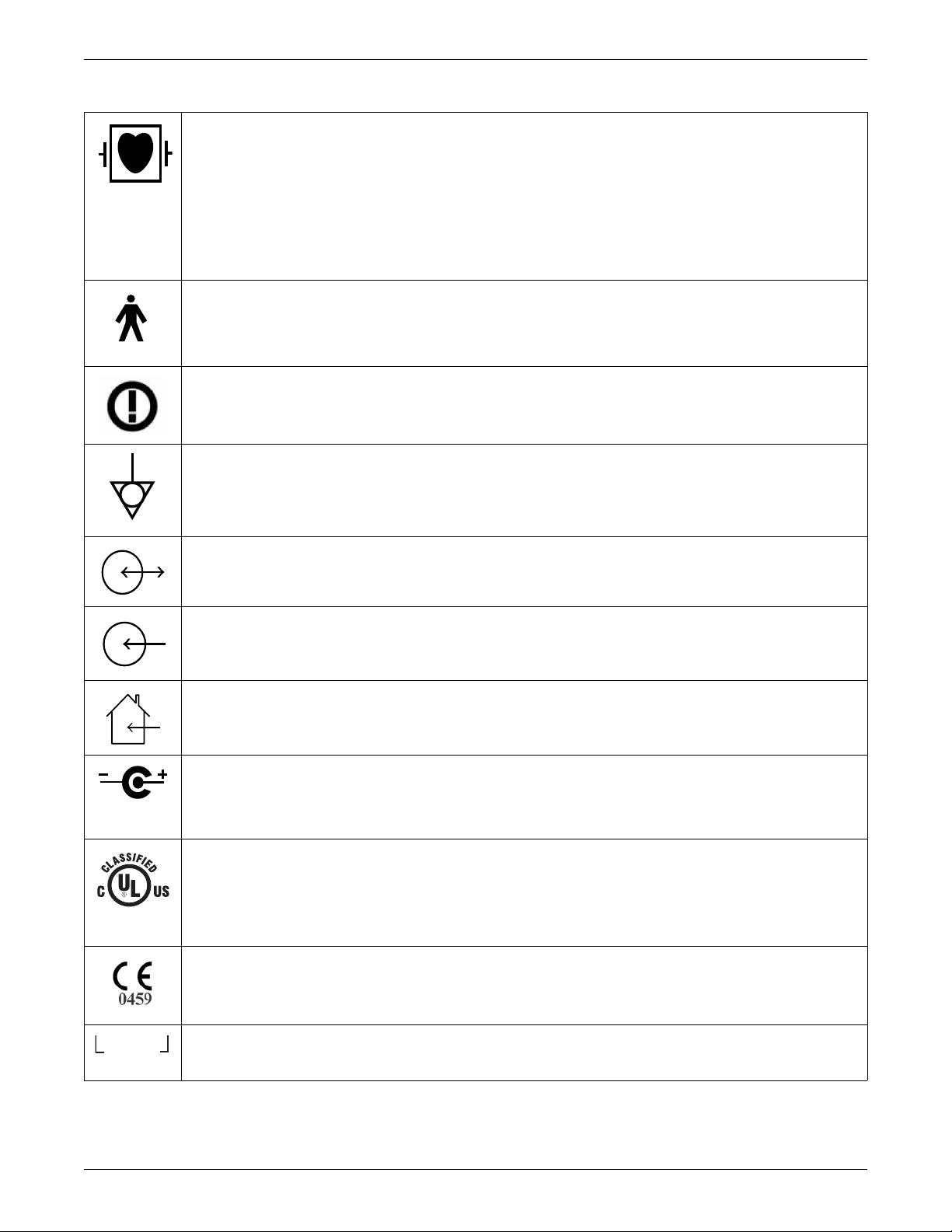
Type CF applied part: Isolated (floating) applied part suitable for intentional external and internal application to the patient
including direct cardiac application. “Paddles” outside the box indicate the applied part is defibrillator proof.
[Medical Standard Definition:] F-type applied part (floating/isolated) complying with the specified requirements of IEC
60601-1/UL 60601-1/CSA 601.1 Medical Standards to provide a higher degree of protection against electric shock than
that provided by type BF applied parts.
NOTE
The rating of protection against electric shock (indicated by symbol for CF) is achieved only when used with patient
applied parts recommended by GE.
TYPE B APPLIED PART: Non-isolated applied part suitable for intentional external and internal application to the patient
excluding direct cardiac application.
[Medical Standard Definition:] Applied part complying with the specified requirements of IEC 60601-1/UL 60601-1/CSA
601.1 Medical Standards to provide protection against electric shock, particularly regarding allowable leakage current.
R&TTE equipment class 2 identifier: An alert sign, indicating that transmitting radio equipment operates in nonharmonized frequency bands and can cause interference.
Equipotential
4P41
DC In/RF Out or DC Out/RF In
DC In or RF In
For indoor use only.
Power supply cable configuration.
+ = Power
– = Return
Medical Equipment
With respect to electric shock, fire and mechanical hazards only in accordance with UL 60601-1, and CAN/CSA C22.2 NO.
601.1 and if applicable, IEC 60601-2-27, IEC 60601-2-30, and IEC 60601-2-49.
CE mark CE-0459 indicating conformity with the provisions of the Council Directive 93/42/EEC concerning medical
devices, and fulfills the essential requirements of Annex I of this directive.
Interface Connector(s)
1-4 ApexPro™ 2001989-351A
Page 15
Introduction
2005-08
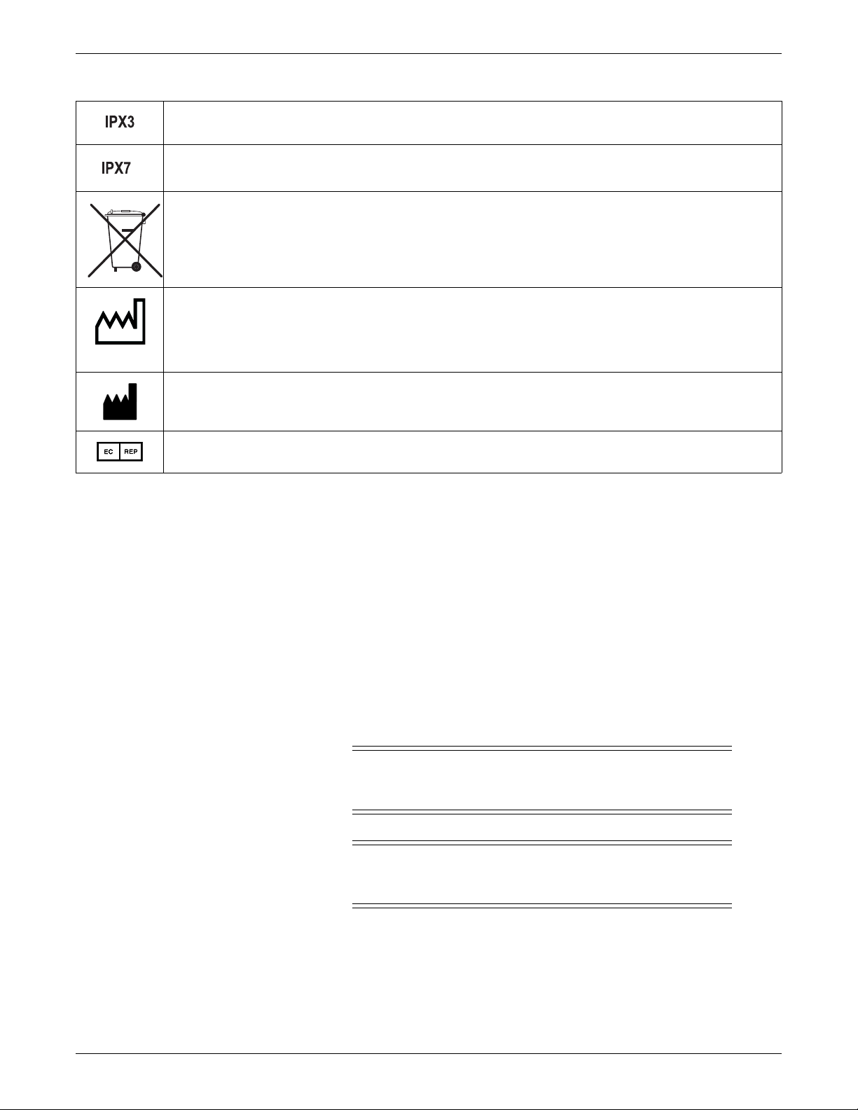
Complies with IPX3 standards for water ingress
Complies with IPX7 standards for water ingress
This symbol indicates that the waste of electrical and electronic equipment must not be disposed as unsorted municipal
waste and must be collected separately. Please contact an authorized representative of the manufacturer for information
concerning the decommissioning of your equipment.
This symbol indicates the date of manufacture of this device. The first 4 digits identify the year and the last 2 digits identify
the month.
Manufacturer name and address.
European authorized representative.
Safety statements
Dangers
Warnings
Danger statements identify an imminent hazard which, if not avoided, will result in
death or serious injury. No danger statements apply to this product.
Warning statements identify a potential hazard or unsafe practice which, if not
avoided, could result in death or serious injury. The following warnings apply to this
product.
WARNING
BEFORE USE —Periodically, and whenever the integrity of the
device is in doubt, test all functions.
WARNING
EXPLOSION HAZARD —Do not use this equipment in the
presence of flammable anesthetics, vapors or liquids.
2001989-351A ApexPro™ 1-5
Page 16

Introduction
WARNING
FALSE CALLS—False low heart rate indicators or false asystole
calls may result with certain pacemakers because of electrical
overshoot.
WARNING
INTERFACING WITH OTHER EQUIPMENT —Contact GE for
information before connecting any devices to the equipment that are
not recommended in this manual.
WARNING
LOSS OF DATA — Notify the affected users relying upon this data
flow before shutting down the ApexPro™ antenna infrastructure
components for any reason.
WARNING
MONITORING PACEMAKER PATIENTS —Monitoring of
pacemaker patients can only occur with the pace program activated.
WARNING
PACEMAKER SPIKE —An artificial pacemaker spike is displayed
in place of the actual pacemaker spike. All pacemaker spikes appear
uniform. Do not diagnostically interpret pacemaker spike size and
shape.
WARNING
P ATIENT HAZARD —A pacemaker pulse can be counted as a QRS
during asystole in either pace mode. Keep pacemaker patients under
close observation.
WARNING
RATE METERS—Keep pacemaker patients under close
observation. Rate meters may continue to count the pacemaker rate
during cardiac arrest and some arrhythmias. Therefore, do not rely
entirely on rate meter alarms.
Cautions
Caution statements identify a potential hazard or unsafe practice which, if not
avoided, could result in minor personal injury or produ ct/property damage. The
following cautions apply to this product.
1-6 ApexPro™ 2001989-351A
Page 17

Introduction
CAUTION
ACCESSORIES (SUPPLIES) —To ensure patient safety, use only
parts and accessories manufactured or recommended by GE.
Parts and accessories used must meet the requirements of the
applicable IEC 60601 series safety standards, and/or the system
configuration must meet the requirements of the IEC 60601 medical
electrical systems standard.
CAUTION
ACCESSORIES (EQUIPMENT) —The use of accessory equipment
not complying with the equivalent safety requirements of this
equipment may lead to a reduced level of safety of the resulting
system. Consideration relating to the choice shall include:
use of the accessory in the patient environment; and
evidence that the safety certification of the accessory has been
performed in accordance to the appropriate IEC 60601-1 and/or
IEC 60601 harmonized national standard.
CAUTION
FDA POSTMARKET SAFETY ALERT—The United States FDA
Center for Devices and Radiological Health issued a safety bulletin
October 14, 1998. This bulletin states “that minute ventilation rateadaptive implantable pacemakers can occasionally interact with
certain cardiac monitoring and diagnostic equipment, causing the
pacemakers to pace at their maximum programmed rate.”
The FDA further recommends precautions to take into
consideration for patients with these types of pacemakers. These
precautions include disabling the rate responsive mode and
enabling an alternate pace mode. For more information contact:
Office of Surveillance and Biometrics, CDRH, FDA
1350 Piccard Drive, Mail Stop HFZ-510
Rockville, MD 20850
U.S.A.
CAUTION
POWER REQUIREMENTS —If the installation of the equipment,
in the USA, uses 240V rather than 120V, the source must be a
center-tapped, 240V, single-phase circuit.
CAUTION
RESTRICTED SALE —Federal law restricts this device to be sold
by or on the order of a physician.
2001989-351A ApexPro™ 1-7
Page 18

Introduction
Notes
CAUTION
SUPERVISED USE —This system is intended for use under the
direct supervision of a licensed health care practitioner.
Note statements provide application tips or other useful information to assure that you
get the most from your equipment. The following notes apply to this product.
NOTE
ECG monitoring with patients on non-invasive transcutaneous pacemakers may
not be possible due to large amounts of energy produced by these devices.
Monitoring ECG with an external device may be needed.
NOTE
This device is not intended for home use.
NOTE
Service information
Service requirements
Follow the service requirements listed below.
Refer equipment servicing to GE authorized service personnel only.
Any unauthorized attempt to repair equipment under warranty voids that
It is the user’s responsibility to report the need for service to GE or to one of their
Failure on the part of the responsible individual, hospital, or institution using this
Regular maintenance, irrespective of usage, is essential to ensure that the
Patient environment is any volume in which intentional or unintentional cont act
can occur between patient and parts of the system or between patient and other
persons touching parts of the system. (IEC 60601-1-1)
warranty.
authorized agents.
equipment to implement a satisfactory maintenance schedule may cause undue
equipment failure and possible health hazards.
equipment will always be functional when required.
1-8 ApexPro™ 2001989-351A
Page 19
Equipment identification
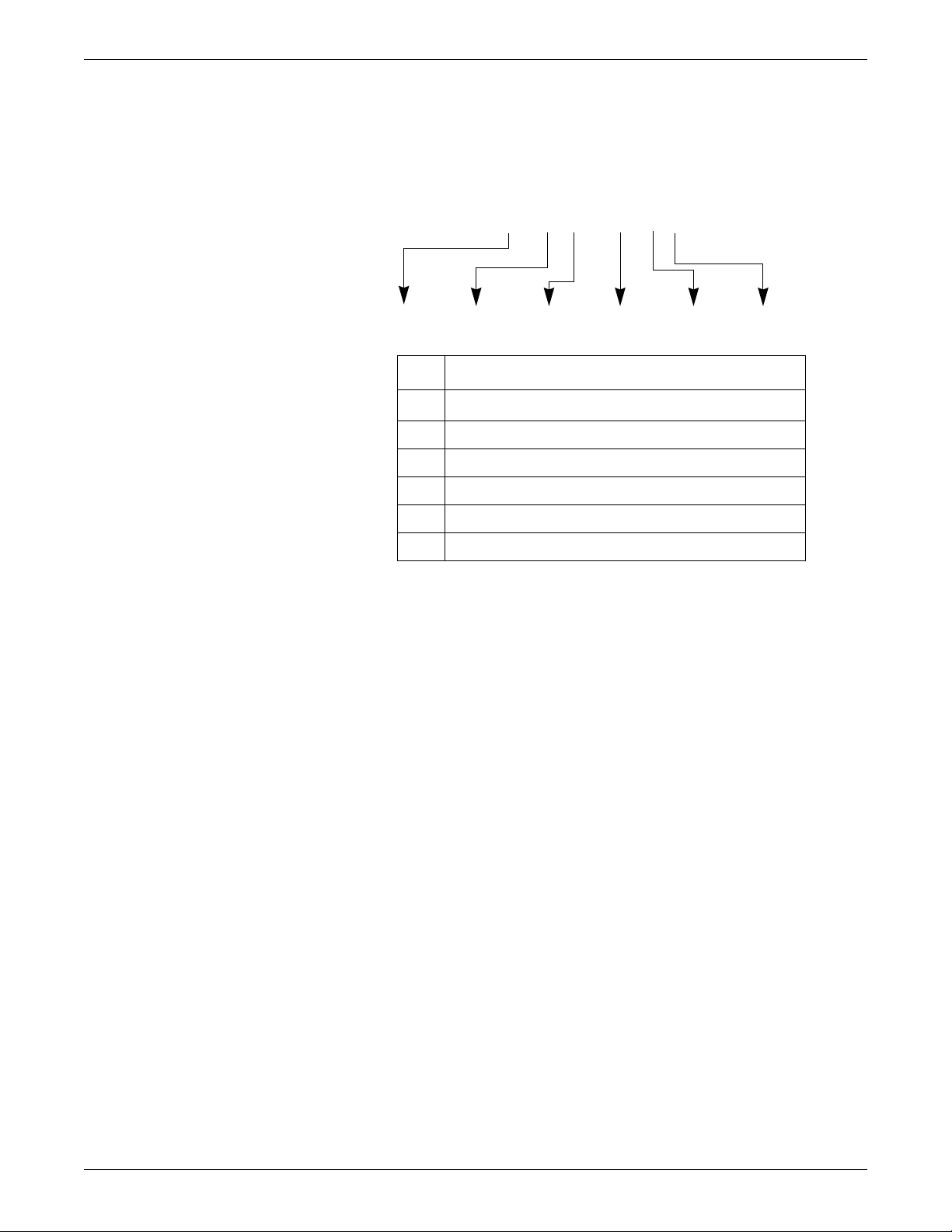
### ## ## #### # #
ABCDEF
Every GE device has a unique serial number for identification. A sample of the
information found on a serial number label is shown below.
Introduction
Description
A
B year manufactured
C fiscal week manufactured
D production sequence number
E manufacturing site
F miscellaneous characteristic
product code
1
The product code is: TT for ApexPro transmitter, domestic; AM for
ApexPro transmitter, international; T9 for Ap exPro CH transmitter;
SE3 for the CARESCAPE Telemetry T14 transmitter; RTS for US
(560-614 MHz) ApexPro receiver subsystem; and RAV for
international (420-474 MHz) ApexPro receiver subsystem.
1
2001989-351A ApexPro™ 1-9
Page 20

Introduction
1-10 ApexPro™ 2001989-351A
Page 21

2
Equipment Overview
2001989-351A ApexPro™ 2-1
Page 22

Equipment Overview
System overview
Overview
A transmitter is directly connected to the patient and transmits monitored data via the
antenna to a corresponding receiver in a one-to-one correspondence between
transmitters and receivers. Up to 16 receivers (four quad receiver modules with four
receivers on each) may reside in a receiver system. Up to four quad receiver modules
connect to the receiver backplane PCB, which is responsible for managing
communications between all connected receivers and the telemetry host application
software on the PC. The communication between the PC and the receiver backplane
is 10BaseT Ethernet and is called the Receiver-Exchange (RX) network. The host
application software processes the patient data from the receivers and makes the
patient’s ECG parameter and waveform data available for display at network viewing
stations or the Clinical Information Center (CIC) central station.
The ApexPro telemetry system consists of the following components:
Patient monitoring equipment
Apex oximeter (optional)
Xpod oximeter (optional)
Accutracker DX noninvasive blood pressure monitor (optional)
DINAMAP PRO 100, 200, 300, and 400 series monitor (optional)
Transmitter (one for each monitored patient)
ApexPro transmitter, or
ApexPro CH transmitter
Antenna system
ApexPro antenna system
Receiver antenna
Attenuator
Antenna splitters/combiner
Amplifier
Bias tee
Antenna filter as needed (bandpass and/or notch)
DC power source to power the receiver antennas and antenna amplifiers
Enterprise Access antenna system.
Refer to the Enterprise Access System Service Manual for more details.
Receiver system (holds up to 4 ApexPro quad receivers)
Unity Network
ApexPro Telemetry Server (ATS) with ApexPro software
PC with CIC Pro Clinical Information Center (CIC)
2-2 ApexPro™ 2001989-351A
Page 23
Power requirements
Transmitter
Monitor(s)
Attenuator
Attenuator
Cable
Antenna
RX
RF
DC
+12 VDC
1A
Unity MC
Antenna System
Splitter
Bias
Tee
Filter,
Notch,
or
Bandpass
Combiner
ApexPro
Receiver
System
ATS
CIC Pro
Center(s)
Amplifier
Antenna
Cable
Power Supply
Equipment Overview
035B
The DC power requirements for the ApexPro antenna system depend greatly on the
configuration of each individual system. To ease the power requirements of the
ApexPro telemetry system, the power supply for the antenna system is external to the
ApexPro receiver system and separate from the antenna.
Interface with ApexPro receiver subsystem
Each receiver in the quad receiver module, located in the receiver subsystem, receives
data from the transmitters. This data is processed by the receiver system and then
transmitted via the dedicated Ethernet interface to a CIC Pro center for further
processing and display. The quad receivers and the receiver subsystem together are
known as the receiver system.
The interface between the antennas and the receiver system consists of coaxial
cabling and connectors for transferring the transmitted signal. The interface uses 75ohm cable from each antenna field and F style 75-ohm connectors as a connection
medium. The preferred cable is RG-6, but for longer lengths RG-11 may be used.
Interface with multiple ApexPro receiver subsystems
To interface the antenna system with multiple ApexPro receiver systems, each
antenna field in the antenna system is split into the appropriate number of tap points
using combiners/splitters before connecting to each ApexPro receiver system.
Equipment
Unity Network
2001989-351A ApexPro™ 2-3
The Unity Network is the networking system used to transmit information from one
GE product to others connected to the same Unity Network.
Page 24

Equipment Overview
ApexPro antenna system
Antenna
The antenna system is used for transmission of data from the transmitter to the
receiver system.
The antenna is a circularly-polarized array of sloping half-wave dipoles with an omnidirectional coverage pattern. The antenna is available in two versions: active and
passive. An active antenna includes an active amplifier, while a passive antenna
provides no signal amplification. The receiver antenna comes with a standard drop
ceiling T-bar mount.
Antenna amplifier
The antenna amplifier boosts the signal when losses from other antenna components
exceed the gain of the antenna. DC power for the amplifier is obtained from the
+12VDC power supply.
Coaxial cable
Splitters/combiner
Attenuators
Power supply
Coaxial cabling is used to connect the omni-directional antennas and amplifiers to the
receiving equipment. Controlled-impedance cabling is used and 75-ohm, RG-6 type
is recommended. Plenum- or riser-rated cable is used to meet NEC fire codes. RG-11
may be used if cable lengths become long and dB losses become excessive.
Passive splitters/combiners split or combine the RF signal into multiple paths. The
same splitter may also be used as a combiner to join multiple RF signals into one
path. There are two-, four-, or eight-way splitters available that are DC-passive.
Attenuators lower signals and balance antenna runs. The attenuators are DC-passive
and are available as 3 dB, 6 dB and 10 dB attenuators.
A +12VDC power supply at 1A supplies power to the antenna system. Power supplies
accept AC voltages between 90-270VAC. AC inputs have internal fuses that are not
replaceable. The output of the supply is short circuit protected.
Bias tee
The antenna bias tee allows the injection of DC power from the antenna power supply
into the antenna system cabling. The bias tee supplies RF isolation between the RF
signals on the antenna cabling and the power supply. It contains a DC block that
2-4 ApexPro™ 2001989-351A
Page 25

Notch filter
Bandpass filter
Identify antennas
Equipment Overview
blocks the conduction of DC power to the receiver system and associated hardware. A
bias tee is used with each power supply.
Notch filters are frequency or TV channel specific and notch out the TV video, audio,
or digital center of the band signals. Notch filters also filter pager signals or other
strong RF signals that can be found in a telemetry environment.
The bandpass filter rejects frequencies outside its listed bandwidth and passes
frequencies inside its listed bandwidth. It is used in place of certain notch filters to
provide wide band filtering with less in-band loss than multiple notch filters.
Identify the high-power and active antennas by the part number label and the GE logo
only on the front (bottom). The passive antenna looks identical to the high-power
antenna except it has a black cap over the LED power indicator. To visually identify
the antenna type, observe the following:
The -002, -003, -004, and -005 models have an embossed GE logo.
The -006, -007, and -008 models have a blue GE logo.
The -003, -005, and -006 passive antennas have a black cap over the LED power
indicator.
For further identification, check the part number label.
Part number
2000673-002 600 MHz ApexPro Antenna Hi-Pwr
2000673-003 600 MHz ApexPro Antenna
2000673-004 450 MHz ApexPro Antenna Hi-Pwr
2000673-005 450 MHz ApexPro Antenna
Design
frequency
Antenna type Description Status
560-614MHz
Passive 560-614MHz
420-474MHz
Passive 420-474MHz
This high-power antenna operates within 560-614MHz and has
filtering for out-of-band signals. It has >15dB rejection below
470MHz.
This passive antenna has no internal filtering or amplification,
therefore requires no DC voltage. Use this antenna with notch
filters, high- or low-pass filters, or a bandpass filter and an in-line
amplifier. Use only when other antennas do not meet design
requirements.
This high-power antenna operates within 420-474MHz and has
filtering for out-of-band signals. It has >15dB rejection below
320MHz.
This passive antenna has no internal filtering or amplification,
therefore requires no DC voltage. Use this antenna with notch
filters, high- or low-pass filters, or a bandpass filter and an in-line
amplifier. Use only when other antennas do not meet design
requirements.
Obsolete
Obsolete
Obsolete
Current
2000673-006 600 MHz ApexPro Passive
Antenna 560-614MHz
This passive antenna has no internal filtering or amplification,
therefore requires no DC voltage. Use this antenna with notch
filters, high- or low-pass filters, or bandpass filters and an in-line
amplifier. Use only when the other antennas do not meet design
requirements.
Current
2001989-351A ApexPro™ 2-5
Page 26
Equipment Overview
Part number
2000673-007 600 MHz ApexPro Active Antenna
2000673-008 450 MHz ApexPro Antenna Hi-Pwr
Design
frequency
Antenna type Description Status
This active antenna operates within 608-614MHz. This antenna
608-614MHz
420-474 MHz
also has a bandpass filter element that rejects signals outside of
608-614MHz, except for signals in channels 36 and 38.
This high-power antenna operates within 420-474MHz and has
filtering for out-of-band signals. It has >15dB rejection below
320MHz.
For technical specifications, see Antenna specifications on page A-13.
Enterprise Access antenna system
Refer to the Enterprise Access System Service Manual for details on the system.
ApexPro and CARESCAPE transmitters
CAUTION
UNINTENTIONAL RADIO FREQUENCY (RF)
INTERFERENCE—Unintentional RF interference could degrade
the reliability and performance of the wireless data link. The facility
must maintain an RF environment free from unintentional
interference.
Current
Current
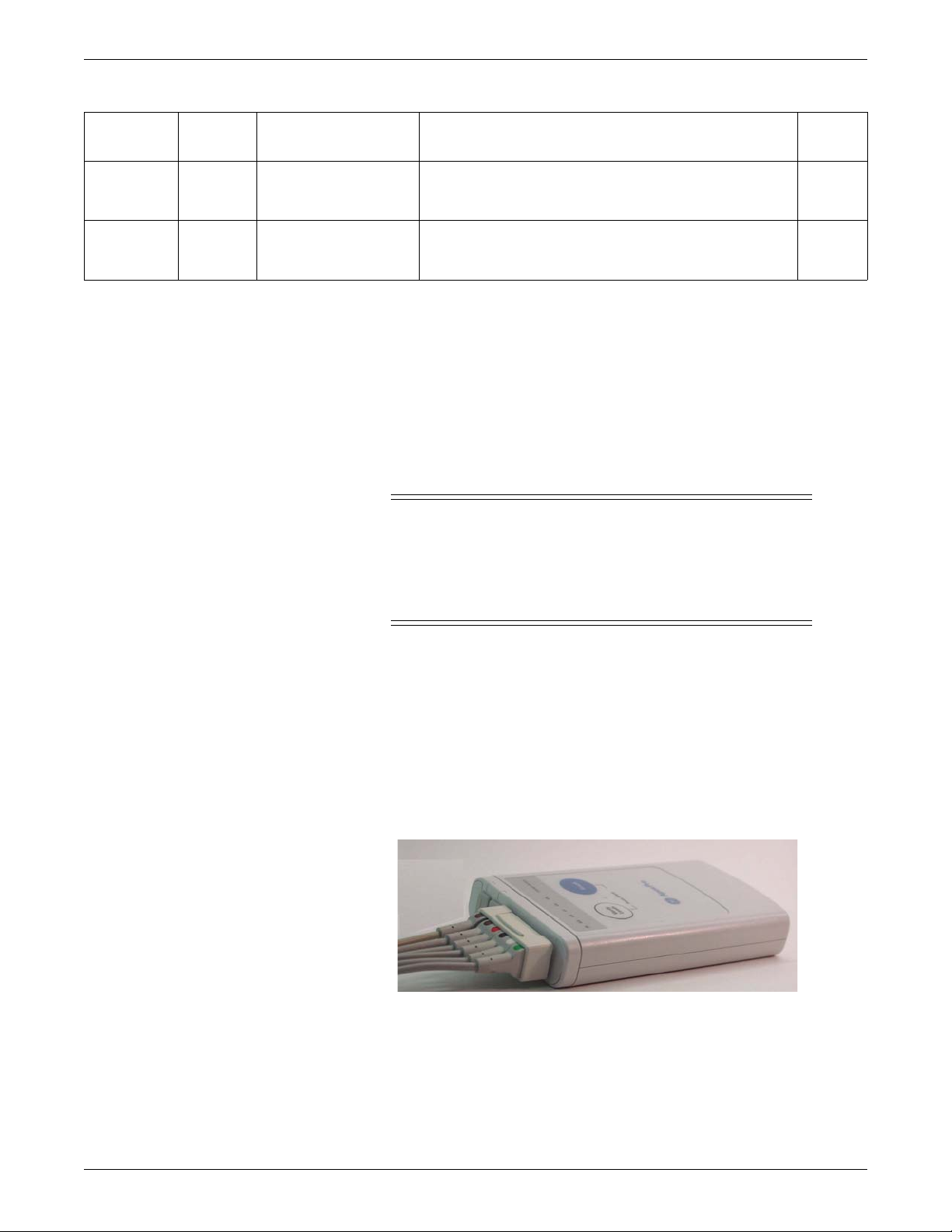
The ApexPro and CARESCAPE transmitters send the patient’s ECG data to the
ApexPro receiver system for processing. Data is then transmitted via a dedicated
Ethernet interface to the CIC Pro center for viewing. The transmitter can also send
DINAMAP PRO data to the CIC Pro center via the DinaLink cable.
Additionally, the transmitter can send the patient’s SpO2 and noninvasive blood
pressure data when the interface connector ports are enabled and when the optional
oximeter and/or Accutracker DX noninvasive blood pressure monitor are connected
to it.
309C
ApexPro Transmitter
2-6 ApexPro™ 2001989-351A
Page 27
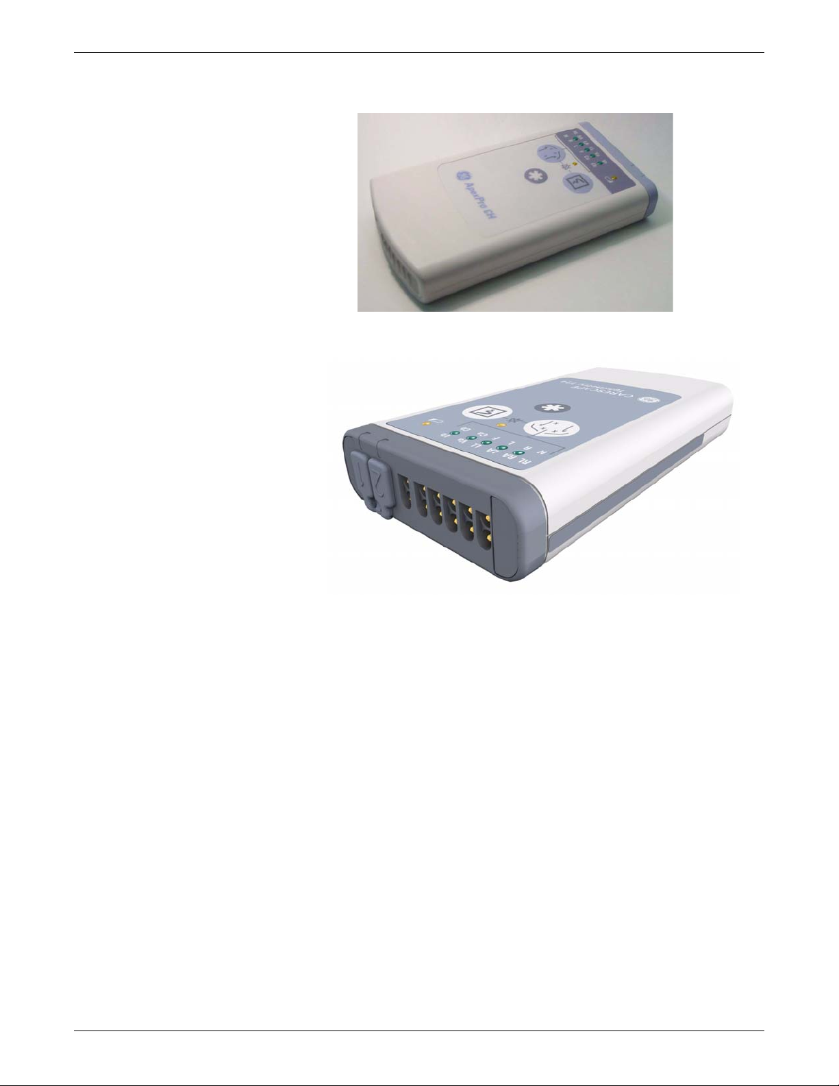
ApexPro CH Transmitter
Equipment Overview
205A
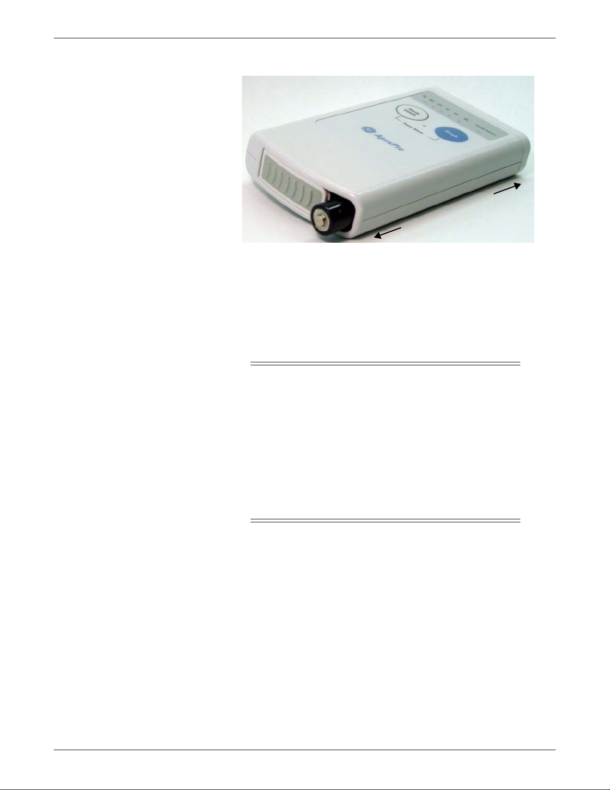
NOTE
Transmitter battery installation
NOTE
Install 2 new AA alkaline batteries in the transmitter.
1. Locate the battery cover at the bottom of the transmitter.
2. Slide the cover over to open the battery compartment.
3. Insert batteries, being careful to follow the polarity signs embossed on the lower
207B
CARESCAPE Telemetry T14 Transmitter
In this manual, wherever the transmitter is shown, the ApexPro, ApexPro CH and
T14 transmitter are valid, except where otherwise noted.
Refer to the ApexPro Telemetry System or the CARESCAPE Telemetry T14
Transmitter Operator’s Manual for further details on battery installation.
back side of the transmitter’s molded case.
2001989-351A ApexPro™ 2-7
Page 28
Equipment Overview
P
o
s
i
t
i
v
e
N
e
g
a
t
i
v
e
220A
4. Close the battery cover.
NOTE
When the Change Battery LED starts flashing, the transmitter has
approximately 1 hour of reserve power before the unit shuts down.
Battery functional life
CAUTION
GE recommends that you always replace both batteries at the same
time. Re-using old batteries or using a combination of old and new
batteries in the transmitter will compromise functionality of the
transmitter and increase the risk of fire hazard.
Do not store the batteries in the transmitter when not in use. Storing
the batteries in the transmitter can cause corrosion of the batteries
and of the transmitter.
Be sure to insert batteries into the transmitter in the correct
direction as indicated on the back of the case. Do not insert batteries
in the reverse direction.
The transmitters runs on 2 AA batteries. For the ApexPro transmitter, the battery life
is approximately 40 hours. For the ApexPro CH transmitter, the battery life is
approximately 120 hours. For the T14 transmitter, the battery life is approximately 65
hours.
For optimum performance, follow these guidelines:
Install 2 new alkaline batteries each time you begin monitoring a new patient or
whenever the Change Battery LED on the transmitter is flashing.
Do not use rechargeable batteries.
Always change both batteries at the same time.
Always use new batteries.
2-8 ApexPro™ 2001989-351A
Page 29
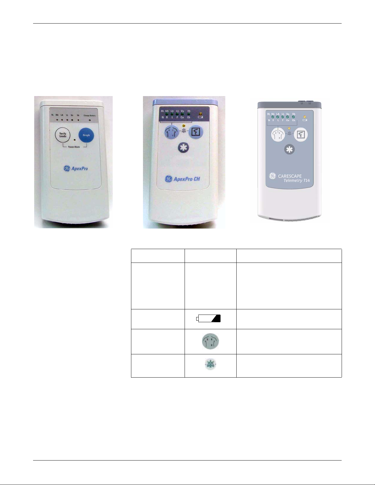
Transmitter controls, indicators and labels
Views
The transmitters have the following buttons and LEDs:
Equipment Overview
605A, 207A, 206B
ApexPro, ApexPro CH, and T14 Transmitters
ApexPro ApexPro CH & T14 Function
RL RA LA LL Va Vb RL RA LA LL Va Vb
N R L F Ca Cb
Change Battery When the battery power is running low, the
Verify Leads
Pause Alarm
When first powered up, the lead LEDs flash
rapidly, followed by two slow flashes. The
transmitter begins functioning after the two
slow flashes.
When any of the transmitter's buttons are
pushed, the lead LEDs flash twice.
change battery LED flashes.
When pressed, the lead LEDs flash twice. If a
lead is valid, its LED stays lit for one minute.
When the Pause Alarm condition occurs, the
pause alarm LED flashes until the condition
ends.
2001989-351A ApexPro™ 2-9
Page 30
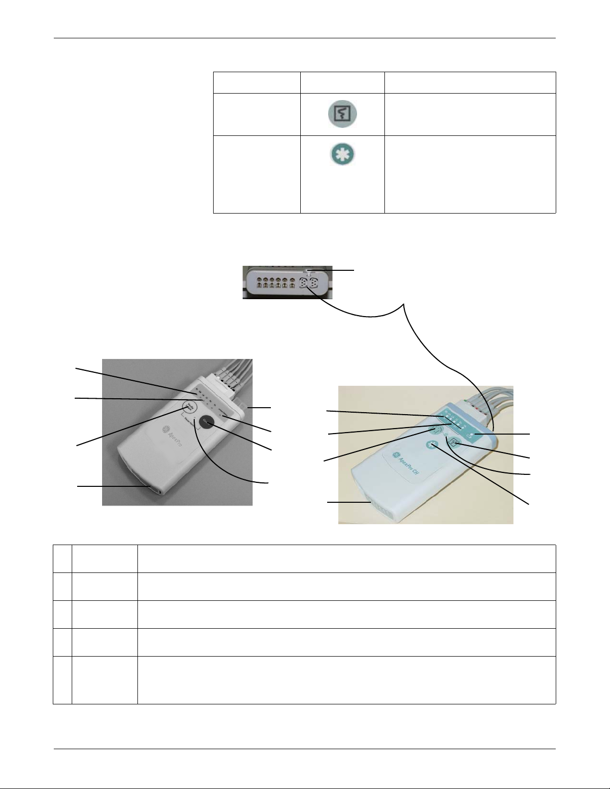
Equipment Overview
F
C
G
H
I
J
H
I
J
K
A
B
C
D
E
A
B
D
ApexPro ApexPro CH & T14 Function
Controls and indicators
Graph
(not available) When pressed, a blue border displays
When pressed, a 20-second graph strip is
printed on the writer or printer.
around the event bed and an alarm tone
sounds at the CIC Pro center. The message
Remote Event displays under the ECG
parameter window for approximately ten
seconds.It also generates a 20-second graph
and saves the event.
317A, 420B, 432A
A RA LED Used in troubleshooting (Frequent lead fail on page 5-21) and when manually viewing or programming the TTX
number (Manually view/program TTX on page 3-19.)
B Good Lead
LEDs
C Verify Leads
button
D Battery
compartment
E Interface
connector
ports
These light when testing the verify leads function.
Checks the lead/skin preparation quality. Pressing the Verify Leads button enables the good lead LEDs. After
pressing this button, the LEDs for good leads illuminate for 1 minute.
Holds 2 AA alkaline batteries. The sliding cover of the compartment also functions as the on/off switch.
The interface connector ports (on the end of the transmitter) are used to connect the transmitter to the APEX
Programming Device. The TTX number and desired reference lead are programmed using the APEX Programming
Device. These interface connector ports may also be used to connect additional parameter devices to the
transmitter.
2-10 ApexPro™ 2001989-351A
Page 31

Equipment Overview
FWell for dust
covers
G Dust covers Transmitters have a set of 2 dust covers, used when the interface connectors are not being used. Markings on the
H Change
Battery LED
I Graph button Initiates the printing of a graph strip. Pressing the Graph button initiates printing a 20-second graph strip to the writer
J Pause Alarm
LED
K Event Marker
button
(Available on
the ApexPro
CH and T14
transmitter
only.)
Location for attaching the set of dust covers.
covers indicate the number of the interface connector port.
The Change Battery LED flashes when battery power is running low and the batteries need changing.
or printer.
To pause the alarms for the programmed amount of time (typically 5 minutes), press the Graph button and the
Verify Leads button simultaneously. The Pause Alarm LED flashes. “ALARM PAUSE” also displays in the patient’ s
waveform window on the CIC Pro center screen. At the end of the pause time, the LED on the transmitter no longer
flashes and alarms are reactivated. T o reactivate the alarms before the pause time has elapsed, press both buttons
simultaneously again.
When pressed, displays a message on the CIC Pro center that a graph is being generated to mark an event. This
function can be turned off at the CIC Pro center.
Labels
The main back label contains the ECG orientation chart, the serial number and any
certification markings required for each country (FCC, UL, etc.) This label also
provides the color coordination for the multi-link cables.
320A
The TTX number label corresponds to the TTX number that is programmed into the
transmitter.
2001989-351A ApexPro™ 2-11
Page 32

Equipment Overview
Transmitter appearance
T14 side labels
The T14 transmitter also has side labels to distinguish it from an ApexPro CH
transmitter. Additional side label kits may be ordered (See T14 on page 6-23.)
321
ApexPro transmitters have 2 user buttons: Verify Leads and Graph. They have a
white endcap on the end opposite the battery compartment cover.
The ApexPro CH and T14 transmitters have 3 user buttons: Verify Leads, Graph,
and Event Marker. There is a blue endcap on the end opposite the battery
compartment cover.
Start-up
At power-up, the transmitter LEDs flash during start-up. The following table defines
the sequence.
Refer to the ApexPro Telemetry System or CARESCAPE Telemetry T14 Operator’s
Manual for further details on transmitter operation and leadwire installation.
Transmitter interfaces
ECG Multi-Link leadwire set
Sequence of LED Flashes Function
All LEDs flash quickly Transmitter memory tests are being
performed.
All LEDs flash slowly twice. Indicates that all LEDs are functional.
The ECG connector is designed to accept 3-, 5- or 6-multi-link leadwire sets. The
ECG data is acquired from the patient through a set of leadwires. The signals are then
amplified, processed, and transmitted.
For ApexPro, ApexPro CH and T14 transmitter, the top set of pins is the ECG signal
lead. The bottom set of pins function as the signal lead shield connections. Also, the
2-12 ApexPro™ 2001989-351A
Page 33

Interface connector ports
Top row LEDs
Switches/LEDs
Equipment Overview
RA shield functions as the RF antenna for the ApexPro and ApexPro CH transmitter;
the T14 transmitter has an internal antenna.
317A
When enabled, interface connector ports provide an asynchronous communication
connection to other devices (NBP, SpO2, etc.) for extra monitoring or for service
connection to a programming box.
When power is applied to the transmitter, all of the LEDs should flash rapidly
indicating code is being loaded. The code is done loading and executed when just the
top row LEDs flash twice.
605A, 205B
While in normal application mode, pressing and releasing the Verify Leads button
causes the LEDs to light up for 1 minute if their corresponding lead is good. Pressing
and releasing the Graph button causes either a save or a manual graph at the CIC Pro
center.
Pressing both the Verify Leads and the Graph buttons together causes an alarm
pause condition for the programmed amount of time (typically 5 minutes) or until the
alarm pause action is initiated again. When the transmitter is in alarm pause, the
corresponding LED flashes once every second at a 1/8th duty cycle.
Upon any activation (Verify Leads, Graph, or Alarm Pause) the top row of LEDs
flash twice. All these functions are disabled in service mode.
2001989-351A ApexPro™ 2-13
Page 34

Equipment Overview
When the battery voltage drops below 1.9 volts for ApexPro,1.6 volts for ApexPro
CH or 1.73 volts for the T14, the Change Battery LED flashes once every second at
a 1/8 duty cycle.
RF
The RF output is transmitted through one of the shield wires on the multi-link cables.
The carrier frequency can be programmed to any frequency within the allowable
band.
DINAMAP PRO series monitors
The DINAMAP PRO 100, 200, 300, and 400 series monitors can be connected to the
transmitter using the DinaLink™ serial cable to monitor SpO2, NBP , and temperature.
Parameter data from the PRO 100–400 series monitors is displayed, trended, and
stored at the CIC Pro center.
The DinaLink interface cable assembly consists of a monitor adapter cable, the
DinaLink adapter, and an interconnection cable. It connects the transmitter to the
PRO 100–400 series monitors and provides electrical isolation. The interconnect
cable connects to either of the optional interface ports on the transmitter
201A
SpO2 oximeter modules
The oximeter is an optional module that, when connected to the transmitter, allows
telemetry monitoring of a patient’s pulse oximetry data. The oximeter must be
connected to an transmitter in order to convey SpO2 data to the CIC Pro center. Only
digital data is available; no waveforms are generated or transmitted .
2-14 ApexPro™ 2001989-351A
Page 35

Apex oximeter
Power
Display
On/Off
Pulse Rate
SpO %
2
Perfusion
oximeter
In red
In infrared
SpO = f
2
(
(
min
max
min
max
(
(
Equipment Overview
310C
NOTE
The telemetry system supports 2 SpO2 oximeter modules:
Apex Oximeter
Nonin Xpod Oximeter
Theory of operation - pulse oximetry
Pulse oximeters shine light (red and infrared) through perfused tissue and detect the
fluctuating signals caused by arterial blood pressure pulses. Well-oxygenated blood is
bright red, while poorly oxygenated blood is dark red. The pulse oximeter determines
functional oxygen saturation of arterial hemoglobin from this color difference by
measuring the ratio of absorbed red and infrared light as the blood volume fluctuates
with each heart beat. Since steady conditions (steady venous blood flow, skin
thickness, bone, finger nails, etc.) do not cause fluctuations, they do not affect the
saturation reading.
Mathematically:
Anything that affects the intensity of the light such as thick or colored skin affects the
maximum and minimum proportionally and thus the ratio minimum/m ax im um does
not change. However, if too little light gets through, the pulse oximeter does not
function.
Pulse oximeters use 2 different wavelengths of light (colors) and thus have the ability
to determine 1 component of blood. Pulse oximeters are calibrated to closely
approximate functional oxygen saturation values. Pulse oximeter oxygen saturation
values will closely approximate laboratory instrument fractional saturation values if
the dysfunctional hemoglobin saturation levels are negligible. If the dysfunctional
hemoglobin is carboxyhemoglobin or methemoglobin, then the difference between
the oxygen saturation value displayed by the Pulse oximeter and the oxygen
saturation values determined by the laboratory instrument are greater as the
dysfunctional hemoglobin levels rise approximately in accordance with the following
formulas:
801
2001989-351A ApexPro™ 2-15
Page 36

Equipment Overview
SpO2 = O2Hb + COHb + MetHb
SaO2 = 100 x O2Hb /(100 - COHb - MetHb)
Where:
SpO2 = Pulse oximeter determined and displayed oxygen saturation in percent
O2Hb = Fractional oxyhemoglobin saturation in percent
COHb = Carboxyhemoglobin saturation in percent
MetHb = Methemoglobin saturation in percent
SaO2 = Functional oxygen saturation in percent
The following table gives examples of the oximeter readings:
Example 1 Example 2
O2Hb = 96 O2Hb = 88
COHb = 0.5 COHb = 8
MetHb = 0.6 MetHb = 2
SpO2 = 97 SpO2 = 98
SaO2 = 97.07 SaO2 = 97.78
The mathematics are fixed in the pulse oximeter hardware and software. Thus, no
field calibrations are needed or are possible. There are no adjustable parts within the
pulse oximeter that affect the calibration.
The function f, depends on the wavelengths of the sensor LEDs. These wavelengths
are fixed by specified manufacturing processes and materials. The sensors are
checked for correct operation before shipping, so no adjustment or calibration is
needed or possible.
Because the pulse oximeter does all critical computations in software and there are no
critical parts to drift; no re-calibration is needed.
Interconnection cables
NOTE
Refer to the ApexPro Telemetry System or CARESCAPE Telemetry T14
transmitter Operator’s Manual for further details on interconnection cables.
Apex oximeter and Accutracker DX
The interconnection cable used to connect the transmitter with the Apex Oximeter
and/or the Accutracker DX blood pressure monitor, and/or the DinaLink serial cable.
2-16 ApexPro™ 2001989-351A
Page 37

Nonin Xpod oximeter
Plugs into the
transmitter
Plugs into the
Nonin SpO2 probe
Plugs into the
transmitter
Equipment Overview
423B
The interconnection cables used to connect the transmitter and the SpO2 probe are a
part of the oximeter module.
502A
ApexPro receiver system
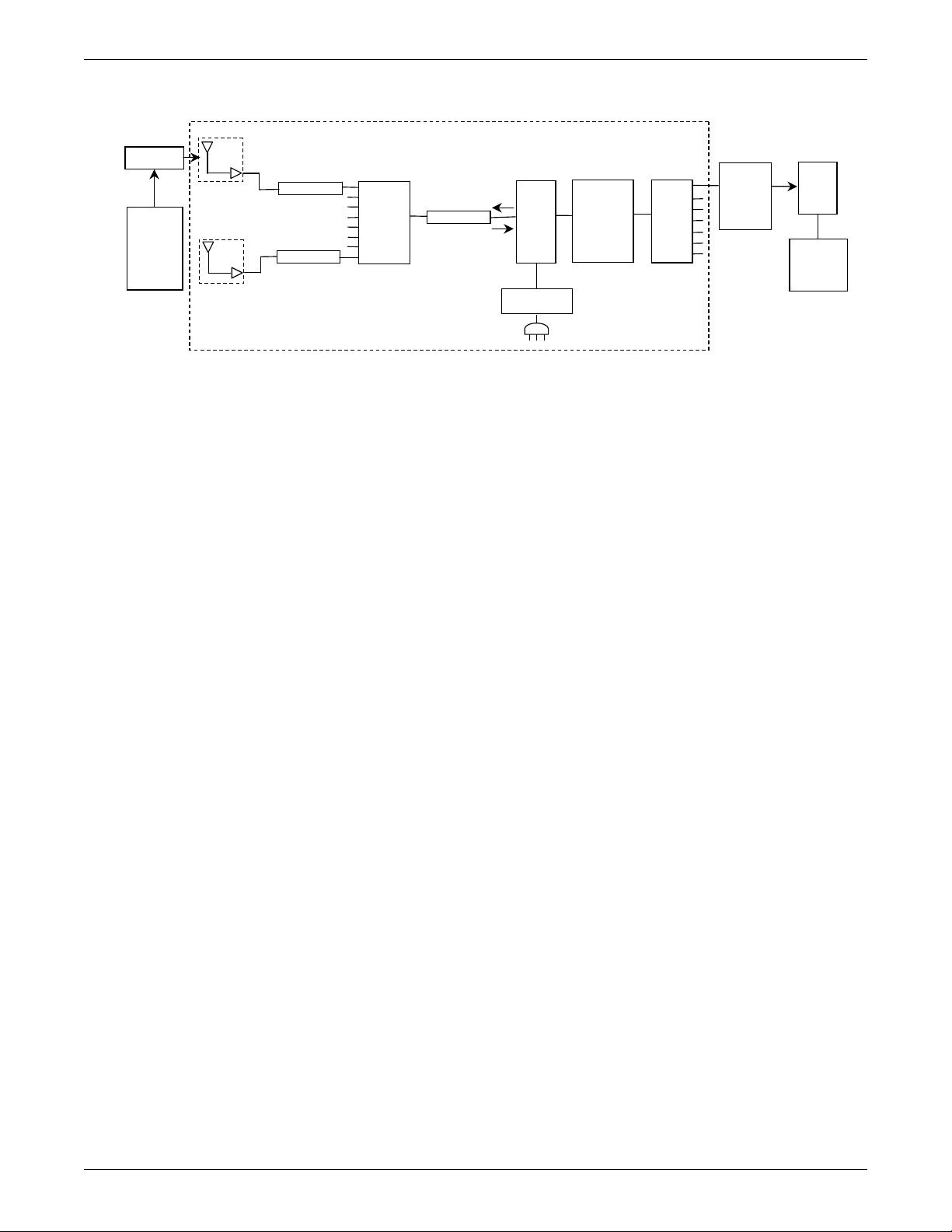
Overview
The Receiver System receives RF signals from the four antenna inputs. These inputs
are for four separate, overlapping fields. The system performs the following
functions:
filters RF (backplane)
distributes RF to quad receiver modules (backplane)
demodulates and decodes transmitter data (quad receiver modules)
retrieves decoded data (backplane)
packetizes and sends data out over RX network (backplane)
The asynchronous serial communication port is for diagnostics, service and
installation information.
2001989-351A ApexPro™ 2-17
Page 38

Equipment Overview
The RX network is directly connected by a network crossover cable to an ApexPro
Telemetry System. The RX network should not be tied to any other network.
Receiver subsystem (backplane)
The subsystem provides an interface between the quad receiver modules and the
telemetry software running on the ApexPro Telemetry System connected via 10BaseT
Ethernet. The subsystem accommodates up to four quad receiver modules. The
subsystem performs the initial amplification and filtering necessary on the RF input
signals from the transmitter.
Quad receiver modules
The quad receiver module receives the GMSK modulated RF signals from the
transmitter through the receiver subsystem (backplane). The RF signals are mixed to
an intermediate frequency, filtered, and mixed again to baseband and re-filtered. The
baseband signal is separated into its in-phase and quadrature components then
sampled. The DSP takes the samples, demodulates, corrects, and decodes packets of
TLINK data. The information is passed on to the receiver subsystem for furthe r
processing and transport over Ethernet. Each module has four functionally identical
receivers.
rcrsysblk
Receiver System Block Diagram
2-18 ApexPro™ 2001989-351A
Page 39

Input/output connectors and signals
F-Connectors, J1, J2, J3, and J4
RJ-45 Ethernet port, J6
Equipment Overview
Pin Description
J1 Antenna A field input
J2 Antenna B field input
J3 Antenna C field input
J4 Antenna D field input
Pin Description
1HOST_XMIT_POS
2HOST_XMIT_NEG
3 HOST_RCV_POS
4N/C
5N/C
6 HOST_RCV_NEG
7N/C
8N/C
RS-232 async comm port, J15
Pin Description
1N/C
2TX
3RX
4N/C
5DGND
6N/C
7N/C
8N/C
9N/C
2001989-351A ApexPro™ 2-19
Page 40

Equipment Overview
Input power plug, J16
Pin Description
1GND
2GND
3GND
4+5V
5+5V
6+5V
2-20 ApexPro™ 2001989-351A
Page 41

3
Installation and configuration
2001989-351A ApexPro™ 3-1
Page 42

Installation and configuration
1
2
3
4
5
Infrastructure installation
Overview
This chapter provides direction for how to install specific parts and gives guidelines
for specific tools to use for installation.
Install coaxial cable
Installation guidelines
Use the hospital scaled prints and the logical antenna schematic to install the cabling.
The logical antenna schematic is generated by ND&I.
Keep the following in mind when installing coax cable.
Always follow the National Electric Code regulations.
Always use PVC for the feed-throughs.
Do not kink the cable. If the cable is kinked, cut out the kinked part and reattach.
Do not pull cable over any metal edges or other abrasive surfaces.
Do not pull cable for one room at a time. The entire cable spool should be
accessible and multiple runs should be pulled at the same time into the ceiling.
Do not lay cable on top of light fixtures.
Lay out cable uniformly and with excess slack. The slack should consist of about
25 cm (1 foot) or so every 3 m (10 feet), both horizontally and vertically.
Do not coil up any extra cable, but instead increase the amount of excess slack
throughout the entire length of cable.
Coaxial cable preparation
These sections describe how to strip coaxial cable and crimp connectors to the cable.
Below are descriptions of the components of a coaxial cable.
1 Center conductor — The center-most feature of coaxial cable. It consists of solid copper
or copper-clad aluminum wire.
2 Dielectric — An electrical insulation utilized to maintain position of the center conductor.
It is composed of polyethylene in either solid or foam state. This insulator/positioner may
3-2 ApexPro™ 2001989-351A
also be evenly spaced solid polyethylene discs.
200A
Page 43

Strippers and crimpers
Installation and configuration
3 Outer conductor or foil — Either solid aluminum tube or an aluminum foil wrap. The cable
size is usually derived from its outside diameter.
4 Braid — Interwoven strands of aluminum or copper mesh. It extends the conductivity of
the outer conductor to the sleeve of the connector.
5 Jacket — The black polyethylene coating over the aluminum outer conductor protects it
from scratches or abrasions during handling and provides a weather-tight seal. The
jacket on plenum cable is made of teflon specified by fire codes.
Recommended tools
The following table indicates the recommended cable strippers and crimpers.
NOTE
The CT611QS will work for both RG-6 Riser and RG-11 Plenum cable.
The current RG-11 crimper will work with the new RG-11 cable and
connector.
The old RG-6 Riser crimp tool will work for the RG-6 Plenum.
Italics = preferred tool.
Following the descriptions is a section describing how to correctly strip coaxial cable.
RG-6 is the recommended coaxial cable, but RG-11 cabling is used for some
installations.
Connector Crimp tool Stripper tool
Part number and
description
2018510-001
RG-6 Plenum
(replaces 1886-008)
2018509-001
RG-6 Riser NP
(replaces 1886-004)
2018511-001
RG-11 Plenum
(replaces 1886-007)
2018512-001
RG-11 Riser NP
(replaces 1886-003)
Thomas
& Betts
(T&B)
PL56CS 0.260 HCT-659
AMF6 0.360 CT611QS
PL11CS 0.470 HCT-211
F11QS 0.470 HCT-211
Hex
0.470 CT611QS
0.470 CT611QS
Tool # and
Manufacturer
CablePrep
T&B
CablePrep
T&B
CablePrep
T&B
Tool # and
Manufacturer
3CSK-GN
Cooper/Xcelite
3CSK-GN
Cooper/Xcelite
RG11 Maxi-Corex, 360
Cooper
RG11 Maxi-Corex, 360
Cooper
Strippers
For RG-6 coax cable, use Xcelite coaxial cable stripper (3CSK-GN).
For RG-11 coax cable, use Cooper cable stripper, RG11 Maxi-Corex 360.
2001989-351A ApexPro™ 3-3
Page 44

Installation and configuration
Coaxial cable
Crimp here
205A
Crimpers
The typical hex crimping tool is shown below. The recommended crimping tool part
numbers are the following.
For RG-6 plenum, use a HCT-659 crimper from CablePrep.
For RG-6 riser, use a CT611QS crimper from T&B.
For RG-11 riser and plenum, use a CT611QS crimper from T&B (recommended)
or HCT-211 crimper from CablePrep.
Before you crimp, check the dimensions for the specific type of coaxial cable and
connector.
215A
RG-6 plenum cable preparation
Required stripping dimensions for RG-6 plenum cabling are shown below.
3-4 ApexPro™ 2001989-351A
Page 45

Installation and configuration
1/4
to
5/16
1/4 1/4
Crimp area
For this cable, use stripper 3CSK-GN from Cooper/Xcelite. The stripper requires 3
blades.
1. To start with a squarely-cut cable end, open the stripper and place the cable so
that 1/4 – 5/16 inch of cable extends past the first blade. Then close and latch the
stripper and rotate around the cable 3 – 4 times.
2. Open the stripper and adjust stripping blades until the correct dimensions are
achieved as shown in the figure above. Then strip the cabling.
a. Expose the center conductor 1/4 – 5/16 inch. Do not score the conductor.
b. Expose the dielectric another 1/4 inch without braid.
c. Expose the braid an additional 1/4 inch. Do not score the braid.
220A
d. Remove and discard excess dielectric, foil and braiding.
3. Place the connector over the prepared cable end.
NOTE
Make sure the braid does not fold back over the jacket.
The connector is properly positioned when the cable dielectric end is flush
with the connector post end.
221A
Position cable dielectric end flush with connector post .
4. Crimp the collar once in the area shown below using a 0.260 inch hex crimp tool.
217A
5. Wrench-tighten the connector.
RG-6 riser cable preparation
Required stripping dimensions for RG-6 riser cabling are shown below.
2001989-351A ApexPro™ 3-5
Page 46

Installation and configuration
1/4” 1/4”
Crimp area
222A
For this cable, use stripper 3CSK-GN from Cooper/Xcelite. The stripper requires 2
blades.
1. To start with a squarely-cut cable end, open the stripper and place the cable so
that 1/4 – 5/16 inch of cable extends past the first blade. Then close and latch the
stripper and rotate around the cable 3 – 4 times.
2. Open the stripper and adjust stripping blades until the correct dimensions are
achieved as shown in the figure above. Then strip the cabling.
a. Expose the center conductor 1/4 inch. Do not score the conductor.
b. Expose the braid another 1/4 inch. Do not score the braid.
c. Remove and discard excess dielectric, foil and braiding.
3. Fold the braid back over the jacket.
218A
4. Place the connector, reversed as shown below , over the cable end until it bottoms
against the braid.
219A
5. Remove the connector. Reverse it once more. Position the connector over the
cable end as shown below. Then push and rotate the connector until it bottoms.
The connector is properly positioned when the cable dielectric end is flush with
the connector post end.
223A
6. Crimp the collar once in the area shown below using a 0.360 inch hex crimp to ol
224A
7. Wrench-tighten the connector.
RG-11 plenum cable preparation
Required stripping dimensions for RG-11 plenum cabling are shown below.
3-6 ApexPro™ 2001989-351A
Page 47

Installation and configuration
1/8”
1/2”
1-1/16”
First crimp
Second crimp
For this cable, use stripper RG11 Maxi-Corex, 360. The stripper requires 3 blades.
1. To start with a squarely-cut cable end, open the stripper and place the cable so
that 1/4 – 5/16 inch of cable extends past the first blade. Then close and latch the
stripper and rotate around the cable 3 – 4 times.
2. Open the stripper and adjust stripping blades until the correct dimensions are
achieved as shown in the figure above.
a. Expose the center conductor 1/2 inch. Do not score the conductor.
b. Expose the dielectric another 1/8 inch without braid.
c. Expose the braid an additional 7/16 inch (a total of 1-1/16 inch from the end
of the center conductor.) Do not score the braid.
225A
d. Remove and discard excess dielectric, foil and braid.
3. Place the connector over the prepared cable end.
NOTE
Make sure the braid does not fold back over the jacket.
4. Push the cable center conductor into the connector until the conductor is inserted
into the contact pin. A slight back-and-forth motion may be necessary to locate
the entryway of the pin, however, avoid excessive twisting of the cable as the
braiding is not to fold back over the jacket.
228A
5. Crimp the collar of the connector in two places, the first beginning at the furthest
ring away from the cable entry end. Using an LRC tool CT611QS, crimp the first
four rings using a .470 size hex. Crimp the last three rings, being careful to align
the resulting hex-shaped areas together.
229A
6. Wrench-tighten the connector.
2001989-351A ApexPro™ 3-7
Page 48

Installation and configuration
1/4”
1/2”
5/8”
Crimp area
RG-11 riser cable preparation
Required stripping dimensions for the first cuts for the RG-11 riser cabling are shown
below.
1. For RG-11 riser coaxial cable, use stripper RG11 Maxi-Corex, 360.T o start with a
2. Open the stripper and adjust stripping blades until the correct dimensions are
230A
squarely-cut cable end, open the stripper and place the cable so that 1/4 – 5/16
inch of cable extends past the first blade. Then close and latch the stripper and
rotate around the cable 3 – 4 times.
achieved as shown in the figure above.
a. Expose the center conductor 1/4 inch. Do not score the conductor.
b. Expose the braid an additional 1/2 inch (a total of 3/4 inch from the end of
the center conductor.) Do not score the braid.
c. Remove and discard excess dielectric, foil, braid and jacket.
3. Fold the braid back over the jacket. Then use the stripper to cut through to the
center conductor an additional 3/8 inch as shown below. Do not score the
conductor. Remove and discard excess dielectric and foil.
4. Insert the connector post over the foil and dielectric until it bottoms.
231A
232A
5. Crimp the collar once in the area shown above using a 0.470 inch hex crimp tool.
6. Wrench-tighten the connector.
3-8 ApexPro™ 2001989-351A
Page 49

Install antennas
Installation and configuration
NOTE
Be sure that after planning and designing the antenna system, the Penetration
Check test (described in the ApexPro Antenna System Installation Test
Instructions) is completed. It is used to estimate the RF penetration of the
hospital construction.
The standard installation for antennas uses a T-bar mount connected to the drop
ceiling support. The retaining clip and pin come with the antenna.
For ceiling tile or dry wall mounting, see Optional antenna mounting kits on page 6-3
to order additional hardware kits necessary for these mounting options. All antenna
mounting installation options and instructions are described in the ApexPro
Telemetry Antenna Mounting Instructions that are included with the antenna.
NOTE
For customer site reasons, some antennas may require installation above the
ceiling. Antennas cannot be mounted in a plenum air shaft, since the antenna is
not plenum rated. For specific guidance on above-ceiling antenna mounting,
contact the Network Design and Integration (ND&I) team.
Install antenna amplifiers
Antenna amplifiers are installed to boost the signal levels from the antenna. The
installation location for the antenna amplifier is generated by the ND&I team for each
site installation.
235A
240A
233A
Standard installation Optional dry wall mount and ceiling tile mount
2001989-351A ApexPro™ 3-9
Page 50

Installation and configuration
DC Out/
RF In
DC In/
RF Out
To receiver system
To antenna
>200 Ft.
Bias
Tee
Power Supply
Antenna
Amplifier
Receiver System
Antenna
To other antennas
DC
4:1
Antenna
Amplifier
Installing antenna amplifier here
increases gain for all antennas
connected to splitter.
Installing antenna amplifier here
increases gain for only one
antenna run.
245A
Do not install antenna amplifiers backwards. Note the markings on the amplifier for
installation orientation. If connected backwards, the LED will illuminate, however the
amplifier will not work correctly; there will be signal loss instead of gain.
250A
3-10 ApexPro™ 2001989-351A
Page 51

Install attenuators
Bias
Tee
Power Supply
Ant.
Amp.
Receiver System
Antenna
4:1
To other antennas
Ant.
Amp.
Attenuator
Attenuator
Installing an attenuator here
attenuates all antennas
connected to the splitter.
Installing an attenuator here
attenuates one antenna run.
Installation and configuration
Attenuators are used to attenuate the signal levels from the antennas. The locations of
the attenuators and the types of attenuators used are determined by the ND&I team for
each site installation.
Install power supplies and bias tees
Power supplies and bias tees are used to power the active antennas and amplifiers
used as part of the antenna system. The number of power supplies used and their
location is determined by the ND&I team. If emergency power is available, the power
supplies are installed on emergency power. Use the power supply/bias tee mounting
bracket to mount both devices to the splitter board to reduce the area needed by each
device.
NOTE
To mount a power supply and bias tee use the Bias Tee and Power Supply
Mounting kit (pn 2010197-001)
255A
2001989-351A ApexPro™ 3-11
Page 52

Installation and configuration
To antenna
To receiver
system
Passive Antenna
To splitter
DC
Block
4:1
Antenna
Amplifier
Notch or
Bandpass
Filter
260A
NOTE
Do not install bias tees backwards. Note the markings on the bias tee for
installation orientation. If connected backwards, the LEDs on all antennas and/or
amplifiers in that specific antenna field run will not illuminate. Neither the
antennas nor the amplifiers will work correctly.
Install notch/bandpass filters
With passive antennas
To protect the antenna system or receiver system from signal overload, notch filters
are installed as determined by the site survey and the ND&I team. Multiple notch
filters and bandpass filters can be used on a given antenna field. Do not install notch
filters on the DC OUT/RF IN side of the bias tee because filter components may be
damaged if DC is applied. Bandpass filters are DC passing and can be installed on
either side of the bias tee.
NOTE
Use the two mounting holds to secure the Cavity Bandpass Filter 608-614 MHz
(pn 2027458-001).
3-12 ApexPro™ 2001989-351A
265A
Page 53

With active antennas
RX
RF
DC
+12 VDC
1A
Unity MC
Splitter
Bias
Tee
Filter,
Notch,
or
Bandpass
ApexPro
Receiver
System
ATS
CIC Pro
Center(s)
Amplifier
Power Supply
ApexPro receiver installation
Installation and configuration
270B
Mounting options
Due to the fact that frequency drift occurs even without power applied, the cailbration
schedule should take into account the date the equipment was last calibrated,
including equipment in storage locations and spares.
Before installation, determine and record the date of initial factory calibration of
transmitters and receivers from the removable calibration sticker that ships on these
devices. If the installation is not within 30 months of the date shown on the
manufacturer calibration sticker, calibrate before installation. See Calibration on page
4-10.
The mounting options for the ApexPro Telemetry System Receiver System are:
Standard tabletop mount (four rubber feet)
Optional rack mount for standard 19 inch network rack system with a 4U panel
height (177.8mm/7in.). (Order rack mounting kit #2004232-001 separately.)
2001989-351A ApexPro™ 3-13
Page 54

Installation and configuration
RackMount
CAUTION
Mount the receiver system securely and away from vibration.
Vibration may cause patient waveform dropout at the CIC.
NOTE
If using rack mount, route all cables to the hinge side so the receivers are
accessible for service. A right angle F-connector may be helpful for the
coaxial cable.
Connections
Keep the following in mind when connecting the system.
Use a dedicated connection between the RX network and the ApexPro Telemetry
System.
3-14 ApexPro™ 2001989-351A
Page 55

Installation and configuration
Antenna
Connectors
Equipotential
Ground
Strain ReliefAC Power Cord
Power
Switch
Ethernet
Async
Comm
If the distance between the ApexPro Telemetry System and the Receiver System
is less than 100 meters (328 ft.) use point-to-point with Ethernet crossover cable
connection.
If the distance is greater than 100 meters (328 ft.) then use either an additional
hub or use fiber optic cable.
1. Connect the RJ-45 (RX network) to the Ethernet port.
2. Connect the coaxial antenna cables to the antenna inputs. Unused antenna input
jacks need to be terminated with a 75 Ohm F-type male terminator.
3. Connect the power cord to the AC power inlet. Secure the cord with the strain
relief. Plug cord into emergency AC power outlet.
4. Indicate which ApexPro Telemetry System is directly connected by labeling the
Receiver System with the ApexPro Telemetry System name. Place the label near
the RX Ethernet port. If desired, this step may be omitted as the ApexPro
T elemetry System can also be identified by using the Blink Rack command at the
ApexPro Telemetry System.
5. Switch the power switch to I (on).
RearPanel
Setup antenna fields
Use the following procedure for configuring receiver subsystem so that it listens to
antenna fields that are setup.
NOTE
The factory default is that all four fields are enabled.
1. Using the 9-pin, serial cable supplied with the tran sm itter programming kit,
connect a PC to Async Comm (asynchronous serial communication) for setup.
2001989-351A ApexPro™ 3-15
Page 56

Installation and configuration
2. At the PC, use a communication program such as HyperTerminal to set up the
ComPort connection.
Port: Com1 (comm port on the PC)
Speed: Baud 19200
Parity: No
Stop Bit: 1
Data Bits: 8
Flow Control: Xon Xoff
3. Press Enter to get the @> Enter Service Password: prompt.
4. Type password , mms_aps (case-sensitive).
5. Press Enter.
6. At the @> prompt type ssf.
The command is “ssf x” where x identifies which antenna field(s) to enable.
Enter the “ssf x” command as listed below to configure the desired antenna
field(s).
X Field D Field C Field B Field A
1 Disabled Disabled Disabled Enabled
2 Disabled Disabled Enabled Disabled
3 Disabled Disabled Enabled Enabled
4 Disabled Enabled Disabled Disabled
5 Disabled Enabled Disabled Enabled
6 Disabled Enabled Enabled Disabled
7 Disabled Enabled Enabled Enabled
8 Enabled Disabled Disabled Disabled
9 Enabled Disabled Disabled Enabled
10 Enabled Disabled Enabled Disabled
11 Enabled Disabled Enabled Enabled
12 Enabled Enabled Disabled Disabled
13 Enabled Enabled Disabled Enabled
14 Enabled Enabled Enabled Disabled
15 Enabled Enabled Enabled Enabled
7. Exit the communication program, then disconnect serial cable and PC, or
continue with step 6 in Setup the receiver on page 3-17.
3-16 ApexPro™ 2001989-351A
Page 57

Setup the receiver
Installation and configuration
Assuming that the ApexPro Telemetry System and all antennas have been installed
and set up, the entire system is now installed and connected.
CAUTION
Equipment damage. If receiver system software needs updating, the
system LED flashes yellow while software is updating. DO NOT
power down the system during a software update.
1. Using the 9-pin, serial cable supplied with the tran sm itter programming kit,
connect a PC to Async Comm (asynchronous serial communication) for setup.
2. At the PC, use a communication program such as HyperTerminal to set up the
ComPort connection. For example:
Port: Com1 (comm port on the PC)
Speed: Baud 19200
Parity: No
Stop Bit: 1
Data Bits: 8
Flow Control: Xon Xoff
3. Press Enter to get the @> Enter Service Password: prompt.
4. Type password , mms_aps (case-sensitive).
5. Press Enter.
6. At the @> prompt type sii.
7. Type information for the following prompts:
Enter Installer’s Name/ID (31 Characters MAX):
Enter Installation Date (31 Characters MAX):
Enter Rack Location (31 Characters MAX):
8. Check the information by typing gii at the prompt.
9. Exit the communication program, then disconnect serial cable and PC.
10. Go to Maintenance on page 4-1 and complete the Receiver System Checkout
procedures to make sure the Receiver System is working properly.
Transmitter installation
Due to the fact that frequency drift occurs even without power applied, the cailbration
schedule should take into account the date the equipment was last calibrated,
including equipment in storage locations and spares.
2001989-351A ApexPro™ 3-17
Page 58

Installation and configuration
Before installation, determine and record the date of initial factory calibration of
transmitters and installation calibration is not within 30 months of the date shown on
the manufacturer calibration sticker, calibrate before installation.See Calibration on
page 4-10.
Programming the transmitter for use
Before use, the transmitter must be programmed. The transmitter is programmed or
upgraded in the field to:
select the operating frequency and corresponding TTX number
select the reference lead
set the alarm pause time
select the filter setting
change the serial number
download new software
Refer to the ApexPro Telemetry Frequency Chart Reference Manual for the operating
frequencies and the corresponding TTX ID numbers.
Refer to the Transmitter Programming Box Programming Instructions for details.
Transmitter configuration
Program code storage
Executable program code for the main processor is stored in non-volatile
programmable memory. Program code can be changed via an interface connector port
using the PC-based programming box software or a HyperTerminal program and a
programming box. The version of the currently stored transmitter code can be
displayed using the transmitter programming box software kit. See Apex, ApexPro
and ApexPro CH Transmitter Programming Instructions.
Error log
The transmitter contains an error log in its non-volatile programmable memory. When
a synthesizer lock error occurs, this is logged and latched into the appropriate
memory space. When a checksum error on start-up occurs, this is logged into the
appropriate memory space for this as well. The error log can be viewed using the
programming box PC software or a HyperTerminal program. This reports both of
these errors as well as a real-time report of the synthesizer lock status.
Parameters
Using HyperTerminal or the ApexPro PC programming box software, certain
transmitter parameters can be viewed and some can be changed while in service
mode.
3-18 ApexPro™ 2001989-351A
Page 59

Installation and configuration
Transmitter Model(s) Parameter Status
ApexPro, ApexPro CH, T14 TTX / Frequency Read / Write
ApexPro, ApexPro CH, T14 Board Version Read
ApexPro, ApexPro CH, T14 Synthesizer Lock Error Log Read / Clear
ApexPro, ApexPro CH, T14 EEPROM Checksum Error Log Read / Clear
ApexPro, ApexPro CH, T14 Synthesizer Lock Status Read
ApexPro, ApexPro CH, T14 Serial Number Read / Write
ApexPro, ApexPro CH, T14 Reference Lead (3-lead) Read / Write
ApexPro, ApexPro CH, T14 Alarm Pause Time Read / Write
ApexPro, ApexPro CH, T14 Code Version (Application) Read
ApexPro, ApexPro CH, T14 Code Version (Manufacturing / Service) Read
ApexPro, ApexPro CH, T14 Filter Read / Write
ApexPro I/Q Table Version Read
ApexPro I/Q Table Write
ApexPro, ApexPro CH, T14 Battery Voltage Read
ApexPro, ApexPro CH, T14 Battery Status Read
ApexPro, ApexPro CH, T14 Lead Status Read
ApexPro, ApexPro CH, T14 Button Status Read
ApexPro, ApexPro CH, T14 App Code Write File
ApexPro, ApexPro CH, T14 Mfg Code Write File
ApexPro CH, T14 RF Test Pattern Read / Write
ApexPro CH, T14 Digital Potentiometers Read / Write
ApexPro CH, T14 LED Test Pattern Write
Manually view/program TTX
After initial programming of the TTX number using the ApexPro Program Device Kit
described in Programming the transmitter for use on page 3-18, the transmitter
frequency or TTX can be viewed or changed without a programming box. The
transmitter always loads code on power-up.
View the TTX number
1. Power up the transmitter. This causes the application to load (indicated by all
LEDs flashing).
2. Hold down the Verify Leads button and the Graph button while the transmitter
loads code and before the top row of LEDs flash twice (this causes the service
code to load). Continue to hold the Verify Leads and Graph buttons.This
displays the TTX number using the first 4 LEDs as follows:
2001989-351A ApexPro™ 3-19
Page 60

Installation and configuration
Pins 2 and 4
Program the TTX number
a. The first 4 LEDs light up indicating it is going to display the 4-digit TTX
number.
b. The RA LED flashes a number of times corresponding to the first digit of the
TTX number. The flashes are from 1 to 10, with 10 flashes representing a
zero digit.
c. The LA LED flashes corresponding to the second TTX digit.
d. The LL LED corresponds to the third digit.
e. The Va LED corresponds to the fourth TTX number.
3. Write down the TTX numbers as they display.
WARNING
Choose a unique TTX number for each transmitter. Programming 2
transmitters to the same TTX number may result in monitoring the
wrong patient.
1. Short connector pin 2 of either interface connector port to pin 4 of that same
interface connector port.
401
2. Power up the transmitter while holding down the Verify Leads and Graph
buttons. This causes the service code to load.
3. The first 4 LEDs (5 on T14 transmitter) of the top row light up indicating it is in
manual TTX program mode.
4. Release the Verify Leads and Graph buttons.
The RA LED flashes corresponding to the number of the first digit of the TTX
number.
5. Increment the first digit by pressing the Verify Leads button repeatedly. Each
time you press the button, the current digit is increased by 1.
6. Release the Verify Leads button when you reach the desired number.
At this point, the LED begins to flash again, indicating acceptance of your entry.
The LED flashes the number corresponding to the new number.
3-20 ApexPro™ 2001989-351A
Page 61

Installation and configuration
7. Proceed to the next digit by pressing the Graph button until the next LED
flashes.
8. Repeat for all 4 (5 for T14 transmitter) digits.
The TTX number is not changed until the fourth/fifth digit is accepted by
pressing the Graph button. The top row LEDs flash twice upon acceptance of the
TTX number.
9. To exit service mode, remove the short from pins 2 and 4. The service program
runs until the short is removed. Then the transmitter reloads the application code
and continues to run normally at the new TTX number.
2001989-351A ApexPro™ 3-21
Page 62

Installation and configuration
3-22 ApexPro™ 2001989-351A
Page 63

4
Maintenance
2001989-351A ApexPro™ 4-1
Page 64

Maintenance
ApexPro CH Telemetry Tune-Up
Introduction
To make sure the ApexPro CH antenna infrastructure remains in proper operational
and functional order, a proper maintenance schedule must be observed.
RF environment changes
Changes in the RF environment could adversely affect the output of the original
design of the antenna infrastructure.
Schedule
WARNING
LOSS OF DATA—The manufacturer requires that calibration be
performed by service personnel as follows:
For 1395-1400 MHz systems calibrate the following every 2 years:
T14 transmitter
RIM 1400
Receiver subsystem
Due to the fact that frequency drift occurs even without power applied, the cailbration
schedule should take into account the date the equipment was last calibrated,
including equipment in storage locations and spares.
Determine and record the date of initial factory calibration of transmitters and
receivers from the removable calibration sticker that ships on these devices. Calibrate
within 30 months of the date shown on the manufacturer calibration sticker or 24
months after installation, whichever occurs first, and every 24 months thereafter.
Additionally, the manufacturer recommends that service personnel perform the
following maintenance procedures upon installation of antenna infrastructure, prior to
every antenna expansion, and every 12 months thereafter.
4-2 ApexPro™ 2001989-351A
Page 65

Antenna infrastructure tests
Subsystem tests
Test
Quick Antenna System Checks. See Quick antenna system checks on page 5-7.
ApexPro CH Antenna System Test Instructions:
Antenna System installation verification tests
Out-of-Band RF Signal Test
Unity Signal Gain Test with Transmitter
Noise Floor Performance Test
In-band Noise Test
Maintenance
Transmitter tests
Test
Visual inspection - General. See Visual inspection on page 4-4.
Cleaning. See Cleaning on page 4-5.
Receiver calibration (Systems that include T14 transmitters only. Only need to
perform every two years). See Receiver calibration on page 4-15.
Receiver System Checkout. See Receiver system checkout on page 7-3.
LED Status Indicators
Verify Connectivity
Receiver Function
Electrical Safety Tests. See Electrical safety tests on page 7-7.
Test
Transmitter calibration (T14 transmitters only. Only need to perform every two years).
See Transmitter calibration on page 4-10.
2001989-351A ApexPro™ 4-3
Page 66

Maintenance
Visual inspection
Inspect for damage
The following steps check for obvious damage.
General
Inspect the equipment (transmitter, receiver, etc.) case for cracks or other
physical damage. Do not use a transmitter that is damaged. Refer all
damaged equipment to qualified personnel.
Inspect all external connections for loose connectors or frayed cables. Have
any damaged connectors or cables replaced by qualified service personnel.
Transmitter
Inspect the transmitter case for damage that may affect the environmental
seals (such as if the unit was dropped and the case seals opened as a result of
the impact). Do not use a transmitter that has seals that have been
compromised.
Inspect the membrane switch for the Graph and Verify Leads controls. If
the membrane is cracked or damaged, do not use the transmitter.
Inspect the leadwire connections for corroded or bent connector pins. Do not
use a transmitter with bad leadwire connectors.
Inspect the leadwires for cracks or other damage. Replace leadwires that are
cracked, damaged, or no longer flexible.
Open battery compartment and inspect the battery contacts. Clean them if
they are dirty or corroded.
The battery compartment is not sealed and may be exposed to moisture. If
there are any visible signs of moisture within the battery, return for service.
Inspect the dust covers before each use to verify that they are securely
attached.
If a transmitter or leadwires fail any of the above inspections, immediately service or
replace it.
Verify transmitter features
The model of the transmitter is indicated by its features and appearance. Use this
chart to ensure that the transmitter is as expected:
Model Feature Transmitter Appearance
ApexPro User buttons 2: Verify Leads and Graph
Port covers Gray interface connector port covers
ApexPro
CH & T14
4-4 ApexPro™ 2001989-351A
User buttons 3: Verify Leads, Graph and Event Marker
Port covers Blue interface connector port covers, label and endcap
Page 67

Verify labels
Cleaning
Maintenance
Follow these steps to be sure that the TTX number shown on the transmitter is the
same as the programmed TTX number:
1. Verify that the Switch Label is present and securely attached to the front of the
case.
2. Determine the programmed TTX number. For more information, see View the
TTX number on page 3-19.
3. Verify that the data recorded on the TTX label on the back of the transmitter is
accurate for the transmitter.
CAUTION
Make sure the TTX numbers match. Failure to do so may result in
monitoring the wrong patient.
All equipment should be cleaned on a regular basis. Comply with the policies of your
institution’s infection control unit and/or biomed department. The decision to
disinfect or sterilize must be made per your institution’s requirements with an
awareness of the effect on the integrity of the transmitter and leadwire.
WARNING
Disconnect AC-powered equipment from the power line before
cleaning or disinfecting its surface. Turn off the power to batterypowered equipment before cleaning or disinfecting its surface.
CAUTION
Never immerse devices, cables, or leadwires in any liquid.
CAUTION
Do not pour or spray any liquid directly on cables or leadwires or
permit fluid to seep into connections or openings.
CAUTION
Never use conductive solutions, solutions that contain chlorides,
wax, or wax compounds to clean devices, cables or leadwires.
2001989-351A ApexPro™ 4-5
Page 68

Maintenance
CAUTION
Never use solutions or products that contain the following:
Any type of Ammonium Chloride such as, but not limited to:
Dimethyl Benzyl Ammonium Chloride
Quaternary Ammonium Chloride solutions
Abrasive cleaners or solvents of any kind
Acetone
Ketone
Betadine
Alcohol-based cleaning agents
Sodium salts
CAUTION
Never autoclave or steam clean devices, cables or leadwires.
CAUTION
Do not attach the device to a patient until it is thoroughly dry.
CAUTION
IMPROPER TRANSMITTER/LEADWIRE APPLICATION —
Applying a transmitter and/or leadwire that is not thoroughly dry to
a patient can result in an electrically conductive path being
established and a Leads Fail alarm not being provided if leadwires
come off the patient.
Cleaning products to avoid
Cleaning products known to cause the types of problems listed above include, but are
not limited to:
Sani-Cloth Wipes
Ascepti Wipes
HB Quat
Clorox Wipes (they do not contain bleach)
Over-the-counter detergents (e.g. Fantastic, Tilex, etc.)
Products that contain active ingredients and solutions similar to these products should
also be avoided.
Transmitter/device cleaning
These instructions apply to transmitters and any other devices, such as oximeters,
blood pressure monitors, etc.
4-6 ApexPro™ 2001989-351A
Page 69

Results of improper cleaning
Appearance of waveforms when the device is not connected to a patient, causing
Brittle and breaking device case.
Overall system performance degradation.
Melting, dulling, or distorting the case.
Total handheld medical device failure requiring replacement.
Unit malfunction.
Void warranty.
Cleaning/disinfecting
1. Remove all batteries and leadwires.
2. Close the battery door before cleaning the device.
3. Wipe the exterior of the device with a soft lint-free cloth, using the following
Maintenance
false alarms instead of a Leads Fail alarm and may not provide a visual and/or
audible Leads Fail alarm.
solution as recommended in the APIC Guidelines for Selection and Use of
Disinfectants (1996):
Storage
Sodium hypochlorite (5.2% household bleach) minimum 1:500 dilution
(minimum 100 ppm free chlorine) and maximum 1:10 dilution.
Any sodium hypochlorite wipe product that meets the above guidelines of
can be used.
NOTE
Wring excess disinfectant from wipe before using.
NOTE
Any contact of disinfectant solutions with metal parts may cause
corrosion.
4. Allow disinfectant solution to remain on device for a minimum of one minute or
per hospital guidelines.
5. Wipe off cleaning solutions with a clean, moist cloth.
6. Dry thoroughly with a dry lint-free cloth and let air dry for at least 30 minutes.
NOTE
Drying times may vary based on the environmental conditions.
7. Take care not to let fluid pool around connection pins. If this should happen, blot
dry with a soft, lint-free cloth.
Always remove batteries when the device is not in use (even for short periods of
time).
Store in a dry well-ventilated area.
2001989-351A ApexPro™ 4-7
Page 70

Maintenance
Hang the device, use a holder if available.
If leadwires/cables are attached, they should hang straight.
Do not coil leadwires/cables tightly around the device.
ECG cable/leadwire cleaning
Results of improper cleaning
Product discoloration.
Metal part corrosion.
Brittle wires.
Brittle and breaking connectors.
Reduced cables and leadwires life.
Unit malfunction.
Void warranty.
Cleaning/disinfecting
1. Remove cables and leadwires from the handheld device or system before
cleaning.
2. Use care in cleaning leadwires to prevent pulling the long wires from the
connector ends. Metal connections can be pulled away from the connectors.
3. For general cleaning of cables and leadwires, wipe using a lightly moistened
cloth with a mild soap and water solution. Then wipe and air dry.
4. For disinfecting the cables and leadwires, wipe exterior with a soft lint-free cloth,
using the following solution as recommended in the APIC Guidelines for
Selection and Use of Disinfectants (1996):
Sodium hypochlorite (5.2% household bleach) minimum 1:500 dilution
(minimum 100 ppm free chlorine) and maximum 1:10 dilution.
Any sodium hypochlorite wipe product that meets the above guidelines of
can be used.
NOTE
Wring excess disinfectant from wipe before using.
NOTE
Any contact of disinfectant solutions with metal parts may cause
corrosion.
5. Do not immerse either end of a cable or leadwire connector. Immersing or
soaking the connector ends may corrode metal contact ends and affect signal
quality.
6. Wipe off cleaning solutions with a clean, lightly moistened cloth.
7. Dry thoroughly with a dry lint-free cloth and let air dry for at least 30 minutes.
4-8 ApexPro™ 2001989-351A
Page 71

Sterilizing
Storage
Maintenance
NOTE
Drying times may vary based on the environmental conditions.
8. Take care not to let fluid pool around connection pins. If this should happen, blot
dry with a soft, lint-free cloth.
9. Do not use excessive drying techniques, such as oven, forced heat or sun drying.
NOTE
EtO sterilization is not recommended, but may be required for cables and
leadwires. Frequent sterilization will reduce the useful life of cables and
leadwires.
Sterilize with ethylene oxide gas (EtO) at a maximum temperature of 50° C (122° F).
After EtO sterilization, follow the recommendations from the sterilizer manufacturer
for required aeration.
Store in a dry well-ventilated area.
Vertically hang cables and leadwires.
Do not coil leadwires or cables tightly around any medical device.
2001989-351A ApexPro™ 4-9
Page 72

Maintenance
Calibration
Determine and record the date of initial factory calibration of transmitters and
receivers from the removable calibration sticker that ships on these devices. Calibrate
within 30 months of the date shown on the manufacturer calibration sticker or 24
months after installation, whichever occurs first, and every 24 months thereafter.
Transmitter calibration
WARNING
LOSS OF DATA—The manufacturer requires that calibration be
performed by service personnel as follows:
For 1395-1400 MHz systems calibrate the following every 2 years:
T14 transmitter
RIM 1400
Receiver subsystem
Required equipment
Determine target frequency
Determine frequency offset
Spectrum analyzer
Rubber duck antenna
An external 10 MHz reference (accurate to 0.0083 ppm)
Laptop with HyperTerminal
Using the TTX number on the back of the transmitter, look up the target frequency in
the ApexPro Telemetry Frequency Chart Reference Manual and record it here:
Target frequency: _________________
This checks the carrier frequency to verify that it is within the frequency tolerance of
the programmed value.
NOTE
The Rohde & Schwarz FSH3 spectrum analyzer is used for the following steps. If
a different spectrum analyzer is being used, the detailed sub-steps may be
different.
1. Connect a Rubber Duck antenna to the spectrum analyzer to view the transmitter.
2. Do one of the following:
Using a small paper clip, short pins 2 and 4 on either of the interface
connector ports as shown.
4-10 ApexPro™ 2001989-351A
Page 73

Maintenance
Pins 2 and 4
Plug the programming box into one of the two serial ports.
3. Power up the transmitter.
4. Place the transmitter within one foot of the spectrum analyzer.
5. Press PRESET.
6. Connect the external 10 MHz reference to the EXT TRIG IN/EXT REF IN.
NOTE
401
The external reference must be accurate to 0.0083ppm. Ensure that you
allow the external reference to warm up (See the device operators manual).
7. Set the analyzer for external 10MHz reference mode.
a. Press SETUP.
b. Press F3- HARDWARE SETUP.
c. Select BNC I/O MODE and press ENTER.
d. Select EXT REF IN and press ENTER.
8. Ensure the preamplifier is on.
a. Press SETUP.
b. Press F3 - HARDWARE SETUP.
c. Select PREAMP and press ENTER.
d. Select ON and press ENTER.
9. Set the center frequency to match the TTX number of the transmitter being
tested. Refer to the ApexPro Telemetry Frequency Chart Reference Manual for
TTX to frequency comparison.
a. Press FREQ.
b. Type the center frequency for the tested channel and press ENTER.
10. Set the reference amplitude to 0 dBm.
a. Press AMPT.
b. Type in 0, press dBM and press ENTER.
11. Set the span to 50 kHz.
2001989-351A ApexPro™ 4-11
Page 74

Maintenance
a. Press SPAN.
b. Type in 50, press kHz and press ENTER.
12. Set the marker to the peak signal.
a. Press MARKER.
b. Press F3 - SET MARKER.
c. Select Peak and press ENTER.
d. The center maximum peak should be selected.
13. If necessary, set the center frequency to be the same as the marker frequency.
a. Press MARKER.
b. Press F3 - SET MARKER.
c. Select CENTER=MKR FREQ and press ENTER.
14. Set span to 1 kHz.
a. Press SPAN.
b. Type 1, press kHz and press Enter.
15. Set the resolution bandwidth to 100 Hz.
a. Press BW.
b. Press F1 - MANUAL RES BW.
c. Type 100, press Hz and press Enter.
16. Reset the marker to the peak signal.
a. Press MARKER.
b. Press F3 - SET MARKER.
c. Select Peak and press ENTER.
d. The center maximum peak should be selected.
17. Record the frequency of the marker:
Measured frequency: ____________
18. Subtract the transmitter target frequency (Determine target frequency on page 4-
10) from the measured frequency (step 17) and record the value:
________________ - _____________ = ________________
Measured frequency - Target frequency = Frequency difference
NOTE
Multiply MHz by 1000000 (one followed by six zeros) to convert to Hz.
19. Follow the appropriate steps for the transmitter being calibrated.
a. For ApexPro and ApexPro CH transmitters
4-12 ApexPro™ 2001989-351A
Page 75

b. For T14 transmitters:
Adjust T14 transmitter frequency
Maintenance
i. Verify that the difference is no more than ±750Hz.
ii. If the transmitter fails this test, it must be returned for service.
iii. Remove the jumper from the interface connector port. When the jumper
is removed, the transmitter resets and returns to normal operation mode.
i. If the difference is less than or equal to ±130 Hz, no adjustment is
required as the transmitter is within specifications. If the difference is
greater, proceed to Adjust T14 transmitter frequency.
NOTE
If the difference is more that ±1400 Hz from the target frequency,
take the transmitter out of service and contact GE.
WARNING
The T14 transmitter cannot be adjusted more that 1400 Hz over the
lifetime of adjustments. Refer to the previously recorded
adjustments to ensure that the overall total of adjustments is not or
will not be more than 1400 Hz. If it greater than or equal to 1400 Hz
take the T14 transmitter out of service and contact GE.
NOTE
This procedure applies to the T14 transmitters. If the ApexPro or ApexPro CH
transmitter frequency needs to be adjusted, send the unit to GE for service.
1. Remove the jumper from the serial port on th e transmitt er. From the
programming box kit, connect the programming box to the transmitter and the
laptop serial port.
2. Launch HyperTerminal.
3. Configure HyperTerminal to the following settings.
Baud-Rate 9600
Data Bits 8
Parity None
Stop Bit 1
Flow Control None
4. Configure the ASCII setup.
a. Select File > Properties.
b. In the Settings tab, click ASCII Setup...
c. Verify the settings are the same as shown:
2001989-351A ApexPro™ 4-13
Page 76

Maintenance
504A
d. Click OK.
5. Identify and record the band that the transmitter is operating from the following
table:
Band: ___
T14 frequency bands TTX range
Band 0 1395.025-1395.975 10199-10161
Band 1 1396 - 1396.975 10160-10121
Band 2 1397 - 1397.975 10120-10081
Band 3 1398 - 1398.975 10080-10041
Band 4 1399 - 1399.975 10040-10001
6. Type the command
:34<space>X<space>1
NOTE
X is the frequency band recorded in step 5 (e.g. :34 1 1 for band 1)
7. Record the initial pot value shown:
______________
4-14 ApexPro™ 2001989-351A
Page 77

Maintenance
8. If the difference calculated in Determine frequency offset (step 18) is positive,
decrease the pot value by one. If the difference is negative, increase the pot value
by one. Type the command:
CAUTION
Do not move the pot setting by more than one value at a time to
prevent moving the intended set point/frequency too far, which
could cause signal dropout.
:35<space>X<space>1<space>Y
505A
Receiver calibration
Determine target frequency
NOTE
X is the frequency band recorded in step 5, Y is the pot value increased/
decreased by one (e.g. :35 1 1 156)
9. Check the frequency on the spectrum analyzer. If it is not within 130 Hz of the
target frequency, repeat the steps in Adjust T14 transmitter frequency.
10. Once the measured frequency is within 130 Hz of the target frequency the
calibration is complete. Record the total amount of Hz adjusted in the ApexPro
Telemetry Frequency Chart Reference Manual or somewhere it can be tracked
for the lifetime of the transmitter for future calibration reference.
Record the final pot value: _____________
11. Repeat step 8 to program the remaining bands to the same pot setting. (e.g. if
band 1 was set to 156, bands 0,2,3, and 4 should be set to 156).
NOTE
The Rohde & Schwarz FSH3 spectrum analyzer is used for the following steps. If
a different spectrum analyzer is being used, the detailed substeps may be
different.
1. Connect a serial cable between a laptop and the receiver subsystem Async
Comm connector.
2. Launch HyperTerminal.
3. Configure HyperTerminal to the following settings.
2001989-351A ApexPro™ 4-15
Page 78

Maintenance
Baud-Rate 19200
Data Bits 8
Parity None
Stop Bit 1
Flow Control Xon Xoff
4. Configure the ASCII setup.
a. Select File > Properties.
b. In the Settings tab, click ASCII Setup...
c. Verify the settings are the same as shown:
401A
d. Click OK.
5. Press Enter.
6. When prompted, type the password mms_aps and press Enter.
7. At the @> prompt, type ss and press Enter.
8. Determine if patients are admitted to the receiver, use the following graphics for
reference:
If the column next to FQ is all -1 values, no beds are admitted on the receiver
subsystem tested. Proceed to step 9.
4-16 ApexPro™ 2001989-351A
Page 79

Maintenance
If the column next to FQ is displays any hertz values, each hertz value
represents an admitted bed on the receiver subsystem tested. Proceed to step
10.
402A
403A
9. If no beds are admitted, perform the following steps:
a. Type l<space>1<space>1 and press Enter.
NOTE
The command is lower case letter L <space> number one <space>
number one. This will load application one to receiver one.
b. Type sf<space>1<space>600000000 to admit a reserved frequency to
receiver one.
NOTE
The command is sf<space>number one<space> number six followed by
eight zeros.
2001989-351A ApexPro™ 4-17
Page 80

Maintenance
c. Type ss and press Enter to confirm settings. You should see
RX 1 AP 1 FQ 600000000
d. The target frequency when using the 600000000 Hz reserved frequency is
513.15 MHz (513150000 Hz).
e. Proceed to Determine frequency offset on page 4-18.
10. If beds are admitted, perform the following steps:
a. Choose one of the admitted beds from the list shown and use that frequency
for the following.
b. Calculate and record the target frequency:
displayed frequency from the list - 86.85 MHz = target frequency
_____________________Hz - 86850000 Hz = ___________________Hz
NOTE
Multiply MHz by 1000000 (one followed by six zeros) to convert to Hz.
c. Proceed to Determine frequency offset on page 4-18.
Determine frequency offset
1. Connect a rubber duck antenna to the spectrum analyzer and the antenna. If
desired, use a short 75 Ohm jumper cable to connect the antenna to the spectrum
analyzer.
2. Remove the front cover of the receiver, as shown, and place the antenna very
close to the receiver cards.
404A
3. On the spectrum analyzer, press PRESET.
4-18 ApexPro™ 2001989-351A
Page 81

Maintenance
4. Connect the external 10 MHz reference to the EXT TRIG IN/EXT REF IN.
NOTE
The external reference must be accurate to 0.0083ppm. Ensure that you
allow the external reference to warm up (See the device operators manual).
5. Set the analyzer for external 10MHz reference mode.
a. Press SETUP.
b. Press F3- HARDWARE SETUP.
c. Select BNC I/O MODE and press ENTER.
d. Select EXT REF IN and press ENTER.
6. Ensure the preamplifier is on.
a. Press SETUP.
b. Press F3 - HARDWARE SETUP.
c. Select PREAMP and press ENTER.
d. Select ON and press ENTER.
7. Set the center frequency to match the target frequency of the receiver subsystem
being tested.
a. Press FREQ.
b. Type the target frequency, press the correct units button and press ENTER.
8. Set the reference amplitude to -60 dBm.
a. Press AMPT.
b. Type -60, press dBm and press ENTER.
9. Set the span to 1 kHz.
a. Press SPAN.
b. Type 1, press kHz and press ENTER.
10. Set the resolution bandwidth to 100 Hz.
a. Press BW.
b. Press F1 - MANUAL RES BW.
c. Type 100, press Hz and press Enter.
NOTE
Ensure that the antenna is located as close to the back of the receiver as
possible. Depending on the antenna used, the signal will be very small
(–100 dBm or smaller). When positioning the antenna, do not move it
too quickly as the analyzer is doing a three cycle average and the peak
will build. If you do not see a signal, change the center frequency up or
down by 1 kHz up to 4 kHz (signal should not be outside of this range).
Ensure that the resolution bandwidth does not change while doing this.
2001989-351A ApexPro™ 4-19
Page 82

Maintenance
11. Set the trace mode to a three cycle average.
a. Press TRACE.
b. Press F1 - TRACE MODE.
c. Select AVERAGE and press ENTER.
d. Type 3 and press ENTER.
12. Set the marker to the peak signal.
a. Press MARKER.
b. Press F3 - SET MARKER.
c. Select Peak and press ENTER.
d. The center maximum peak should be selected.
13. Record the measured frequency of the marker:
Measured frequency: ____________________
14. Subtract the receiver subsystem target frequency (Determine target frequency on
page 4-15) from the measured frequency (See step 13.) and record the frequency
difference.
Adjust frequency
_______________ - _____________ = _____________
Measured frequency - Target frequency = Frequency difference
NOTE
Multiply MHz by 1000000 (one followed by six zeros) to convert to Hz.
15. If the difference is less than or equal to ±10 Hz, no adjustment is required as the
receiver subsystem is within specifications. If the difference is greater, proceed to
Adjust frequency.
1. In HyperTerminal, type gvd and press Enter.
2. Record the initial DAC value:
_____________
3. Type svd<space>new value (e.g. svd 162).
NOTE
If the difference calculated above is positive, decrease the DAC value by
one. If the difference is negative, increase the DAC value by one.
CAUTION
Do not move the DAC setting by more than one value at a time to
prevent moving the intended set point/frequency too far, which
could cause signal dropout.
4-20 ApexPro™ 2001989-351A
Page 83

Maintenance
4. Check the frequency on the spectrum analyzer. If the frequency is not within 50
Hz of the target frequency, repeat by either further increasing or decreasing the
DAC value by one.
2001989-351A ApexPro™ 4-21
Page 84

Maintenance
4-22 ApexPro™ 2001989-351A
Page 85

5
Troubleshooting
2001989-351A ApexPro™ 5-1
Page 86

Troubleshooting
FWPcR^[^aXb
cWTSa^_^dc^]
cWT282?a^.
8bcWT
_a^Q[T\PR[X]XRP[
XbbdTTV[TPS_aT_
_PcXT]c^dc^UPaTPb^UcfPaT
_TaU^a\P]RTTcRPbhbcT\
R^\_^]T]c_TaU^a\P]RT
X]bcP[[XbbdT^a
d]bdaT.
2[X]XRP[
XbbdT
D]bdaT
F^aZfXcWRdbc^\TaP]S
R[X]XRP[CTRW]XRP[Bd__^ac^]
R[X]XRP[XbbdTb
1TVX]ca^dQ[TbW^^cX]VQhdbX]VcWT
BhbcT\ca^dQ[TbW^^cX]VbTRcX^]^U
cWXbS^Rd\T]c
?TaU^a\aT`dXaT\T]cbX]cWT
bTRcX^]cXc[TSA5Sa^_^dc
STcTa\X]PcX^]
3^Rd\T]ch^daUX]SX]Vb
0]hcWX]V
^cWTacWP]
hT[[^f
F^aZfXcWCTRW]XRP[Bd__^ac^]
]Tcf^aZP]S^cWTaXbbdTb
3^Rd\T]cUX]SX]Vb8UUdacWTa
PbbXbcP]RTXb]TTSTS
V^c^Ca^dQ[TbW^^cX]VcaTT!
HT[[^f
>]cWT282?a^T]bdaTcWPch^dPaT
eXTfX]VP[[[TPSbU^acWT_PcXT]c
caP]b\XccTa?^cT]cXP[bhbcT\Sa^_
^dcXbbdTbPaTX]SXRPcTSQhcWT[^bb
^UP[[[TPSb]^cYdbcPUTf
2^]cX]dTca^dQ[TbW^^cX]VQh_TaU^a\X]V
cWTaT`dXaT\T]cbX]cWTbTRcX^]
cXc[TS@dXRZP]cT]]PbhbcT\RWTRZb
8UP]cT]]PbhbcT\_PbbTb
_TaU^a\cWTaT`dXaT\T]cbX]cWTbTRcX^]cXc[TS
HT[[^fSa^_^dcR^]SXcX^]
3^Rd\T]ch^daUX]SX]Vb
8UUdacWTaPbbXbcP]RTXb]TTSTS
V^c^Ca^dQ[TbW^^cX]VcaTT!
BhbcT\R^\_^]T]c
_TaU^a\P]RTX]bcP[[
FWXRW
R^\_^]T]c
S^h^d
bdb_TRc.
6^c^CaP]b\XccTa
ca^dQ[TbW^^cX]V
caTT
CaP]b\XccTa
ATRTXeTa0]cT]]PbhbcT\
Troubleshooting tree 1
5-2 ApexPro™ 2001989-351A
Page 87

Troubleshooting tree 2
FWPcR^[^aXb
cWTSa^_^dc^]
cWT282?a^.
;XVWc1[dT^a
3PaZ1[dT
Bdb_TRc]Tcf^aZaT[PcTSRPdbT
4]bdaT]Tcf^aZbfXcRWTbPaTX]bcP[[TS
P]S^_TaPcX]V_a^_Ta[h
?TaU^a\0;;aT`dXaT\T]cbX]cWTbTRcX^]
cXc[TSHT[[^fSa^_^dcR^]SXcX^]
3^Rd\T]cUX]SX]VbR^\_[TcTSPcPbWTTcb
P]SS^Rd\T]cP]hbhbcT\R^\_^]T]c
RWP]VTb
HT[[^f
=^cT)
DbT^UPb_TRcad\
P]P[hiTaXbTg_TRcTS
4eP[dPcTcWT
ca^dQ[TbW^^cX]V
caTT UX]SX]Vb
ATUTac^cWTP__a^_aXPcT
282?a^bTaeXRT\P]dP[
U^aR^[^aSTUX]XcX^]b
8\_[T\T]cR^aaTRcXeT
PRcX^]bPRR^aSX]V[h
3^Rd\T]cUX]SX]Vb
8U]TRTbbPahR^]cPRc64
cTRW]XRP[bd__^ac
2^[^ab^cWTa
cWP];XVWc1[dT
3PaZ1[dT^a
HT[[^f
8bcWT_a^Q[T\
b^[eTS.
4]S
HTb
=^
2^]cPRc64
cTRW]XRP[
bd__^ac
2^[[TRccWXbX]U^a\PcX^])
=d\QTa^UQTSbfXcWQ[dTU[PVb
0aTQTSbad]]X]VX]2^\Q^\^ST.
0aTQTSbfXaT[Tbb.
Ch_T^UQTSbXST30B7B^[Pa
8bcWTAG]Tcf^aZad]]X]VcWa^dVWPWdQ
^abcaPXVWcc^cWTbdQbhbcT\.
8U]TRTbbPahR^]cPRc64cTRW]XRP[bd__^ac
Troubleshooting
2001989-351A ApexPro™ 5-3
Page 88

Troubleshooting
FWPcbhbcT\
R^\_^]T]cPaTh^d
WPeX]V_a^Q[T\b
fXcW.
?[TPbTdbTcWT
BhbcT\
ca^dQ[TbW^^cX]V
bTRcX^]^UcWXb
S^Rd\T]c
CaP]b\XccTa
0_Tg?a^ATRTXeTa^aBdQbhbcT\
^a0]cT]]PBhbcT\
FWT]
UaTbWQPccTaXTbPaTUXabc
X]bcP[[TSX]cWTd]XcS^cWT
;43bU[PbW
PbTg_TRcTS.
FWT]
caP]b\XccTaXb
R^]]TRcTSc^cWT_
a^VaP\\X]VQ^gS^TbcWT
\TbbPVTQ^g^]c^_^UcWT
caP]b\XccTa_a^VaP\\X]V
bRaTT]PRZ]^f[TSVT
R^\\d]XRPcX^].
HTb
=^
3^P]h;43b
U[PbW.
0aTcWT
QPccTaXTb
X]bcP[[TS
R^aaTRc[h.
=^
HTb
=^
>15
A0^a;0
^][h.
HTb
?a^Q[T\
b^[eTS.
=^
3^f][^PScaP]b\XccTa0__
P]S<UVR^STb^]RT
8Uh^dPaaXeTWTaTPbTR^]S
cX\T>15XUd]Xc`dP[XUXTb
^cWTafXbTbT]Sc^aT_PXa
HTb
=^
0aT;43b
U[PbWX]V
R^]bcP]c[h.
HTb
=^
4]S
HTb
8]bcP[[
R^aaTRc[h
=^
FWT]
caP]b\XccTaXb
R^]]TRcTSc^cWT
_a^VaP\\X]VQ^gS^TbcWT
CCG]d\QTa^]cWT
caP]b\XccTa\PcRWcWT
CCG]d\QTa
SXb_[PhTS^]
cWTbRaTT].
HTb
FWT]
caP]b\XccTaXb
R^]]TRcTSc^cWT
_a^VaP\\X]VQ^g
S^P[[_^fTad_
bT[UcTbcb
_Pbb.
?a^VaP\caP]b\XccTa
CCG]d\QTac^
aT`dXaTS]d\QTa
=^
HTb
4]cTaBd_TaDbTa\^ST_Pbbf^aS
,\\bNP_bP]S_aTbb2[TPa
5PX[daTbQdcc^]
8Uh^dPaaXeTWTaTPbTR^]ScX\T
>15XUd]Xc`dP[XUXTb*^cWTafXbT
bT]Sc^aT_PXa
=^
8bcWT
_a^Q[T\aT[PcTSc^
Sa^_^dc^aX]cTa\XccT]c
R^\\d]XRPcX^]fXcWcWT
0_Tg?a^bhbcT\.
HTb
HTb
=^
2^]cPRc64CTRW]XRP[
Bd__^ac
3^Tb
cWTd]Xc`dP[XUh
PbP]>15.
BT]Sc^
AT_PXa
HTb
=^
0aTh^d
bdaTcWT
_a^Q[T\XbcWT
caP]b\XccTa.
HTb
=^
?TaU^a\cWTbcT_b^dc[X]TSX]cWT
0_Tg?a^caP]b\XccTaRPaaXTaX\_PXa\T]c
\TPbdaT\T]c_a^RTSdaTbTRcX^]
8Uh^dPaaXeTWTaTPbTR^]ScX\T>15XUd]Xc
`dP[XUXTb*^cWTafXbTbT]Sc^aT_PXa
ApexPro transmitter troubleshooting tree
Use the APEX, ApexPro and ApexPro CH Transmitter Programming Box
Programming Instructions to accomplish the tasks below. Programming Kit: PN
421733-xxx
5-4 ApexPro™ 2001989-351A
Page 89

System troubleshooting
RF drop-out determination
Turn on drop-out flags on the CIC Pro to check the color of any drop-out on the
patient signal lead waveform at the CIC Pro patient view.
1. From the Main CIC Pro screen, select the Setup CIC button.
2. Select the Service Password tab.
3. Type the passwor d mms_com and then select OK. A Command prompt window
is displayed.
4. Type setflags<Space>-mark<Space>all and press Enter on the keyboard to
turn on drop-out flags.
If the color is yellow, suspect RF drop-out on the transmitter, the antenna
system or the receiver system.
If the color is light blue or dark blue, suspect a network issue, not an RF-
related drop-out.
If it is another color, refer to the CIC Pro Service Manual provided with your
system for the cause since this indicates that it is not RF drop-out.
5. Type setflags<Space>-mark<Space>off and press Enter on the keyboard to
turn off drop-out flags.
Troubleshooting
6. Close the Command prompt window and the CIC Setup window.
Yellow drop-out condition
Determine the source of the problem
1. Verify the patient/transmitter is in the coverage area. If not, the system is not at
fault.
2. On the CIC Pro:
Ensure that you are viewing all leads for the patient/transmitter.
If the status is Leads Fail, correct the system. Refer to the operator’s manual
provided with your system.
NOTE
If a shorted-leadwire set is used, an Asystole alarm will sound if the
transmitter is admitted. This alarm can be silenced by turning off all
alarms for this admitted bed.
3. Check the transmitter battery status. If the status is Low Batt, correct the
condition by replacing the batteries with new ones.
NOTE
If needed, refer to the appropriate ApexPro T elemetry Service Manual or the
operator’s manual provided with your system.
2001989-351A ApexPro™ 5-5
Page 90

Troubleshooting
4. Isolate whether the drop-out is related to single or multiple patients in the same
Troubleshoot the transmitter
If the drop-out is related to only a single patient/transmitter, use the following
instructions to duplicate the transmitter on another receiver .
1. From the Main CIC Pro screen, select the Setup CIC button.
2. Select the Service Password tab.
3. Type the passwor d mms_com and then select OK. A Command prompt window
coverage area by verifying if more than one transmitter is dropping out in that
coverage area.
If multiple transmitters drop out in the same coverage area, suspect the
antenna system. See Antenna system troubleshooting on page 5-7.
If only one transmitter is dropping out, suspect transmitter or receiver.
Follow the steps to Troubleshoot the transmitter on page 5-6 or Troubleshoot
the receiver on page 5-6 for specific troubleshooting techniques.
is displayed.
Troubleshoot the receiver
4. Type setflags<Space>-dup<Space>on and press Enter on the keyboard to allow
duplicate transmitters.
NOTE
Once you select this option, you have five minutes to enter the duplicate
TTX numbers. If that is not enough time, simply select this option again and
continue entering TTX numbers.
5. At the CIC Pro center, admit a duplicate TTX four times. You should have the
same TTX admitted five times. This will ensure that the TTX is admitted to at
least two different receiver cards.
6. Type setflags<Space>-dup<Space>off and press Enter on the keyboard when
you want to turn off duplicate TTX.
7. Close the Command prompt window and the CIC Setup window.
If drop-out continues on both receivers, suspect the transmitter. Swap the
transmitter with a known good transmitter. Drop-out should go away.
If drop-out is on one receiver and not the other, See Troubleshoot the
receiver on page 5-6.
If drop-out is on one receiver and not on the other, use the ApexPro Telemetry Server
Service Manual provided with your system to complete the following steps.
1. Isolate which receiver subsystem is attached to the CIC Pro center you’re
viewing by using the service diagnostic tool PTSCONFIG at the CIC Pro center/
telemetry server and the command “blink patient unit|bed*” in order to associate
a care unit/bed number to a receiver in a given rack.
5-6 ApexPro™ 2001989-351A
Page 91

2. Once the receiver subsystem is known, check all LEDs for proper operation.
Verify their status with the Receiver Subsystem LED status chart on page 5-13.
3. Swap the suspected receiver with a known good receiver card. Drop-out should
go away.
If drop-out does not go away, suspect an antenna coverage problem. See Antenna
system troubleshooting on page 5-7.
Quick antenna system checks
1. Check all antennas:
a. Check to see if each antenna’s LED is illuminated.
b. If any antenna’s LED is not illuminated, make sure its power supply is
powered. Apply power to the antenna power supply if necessary.
c. Make sure all cables are properly connected.
d. Replace the power supply if necessary.
Troubleshooting
e. Replace the antenna if necessary.
2. If all antennas are okay, check the antenna amplifiers.
a. Check to see if each antenna amplifier’s LED is illuminated.
b. Make sure the amplifier is properly oriented regarding RF In and DC Out.
c. Make sure all cables are properly connected.
d. Replace any faulty unit(s).
NOTE
If an identical replacement part cannot be found, contact the ND&I
Team to ensure proper system balancing.
Antenna system troubleshooting
Perform the following steps in the listed sequence.
Refer to the ApexPro Antenna System Installation Test Instructions for test details.
1. Obtain the following test equipment and site docu mentation:
Equipment required to perform tests as listed in the ApexPro Antenna
System Installation Test Instructions
Floor plan with antenna placement (-101)
Rack Diagram (-301)
Splitter Board Design Document (-700)
Loss calc spreadsheet (-430)
Clinical Systems Design Tool for site
2. Verify the antenna system meets the requirements of the Out-of-Band RF Signal
Test.
2001989-351A ApexPro™ 5-7
Page 92

Troubleshooting
a. Perform Out-of-Band RF Signal Test.
b. Record data in the Clinical Systems Design Tool.
c. If test passes, go to the next test.
d. If test fails:
i. Troubleshoot signal(s) to suspect antenna(s) and add appropriate
filtering.
ii. Verify by repeating the test.
iii. Update documentation.
3. Verify the antenna system meets the requirements of the Unity Signal Gain Test
with Transmitter.
a. Perform the Unity Signal Gain Test with Transmitter.
b. Record data in the Clinical Systems Design Tool.
c. If test passes, go to the next test.
d. If test fails:
i. Verify that the actual in stallation complies with the system design.
ii. Adjust components as necessary to comply with the design.
iii. Ve rify by repeatin g the test.
iv. Update documentation if appropriate.
v. If test passes, go to the next step.
vi. If test still fails, contact GE technical support .
4. Verify the antenna system noise floor.
a. Perform Noise Floor Performance Test.
b. Record data in the Clinical Systems Design Tool.
c. If test fails:
i. Contact GE technical support.
ii. Notify the Field Product Specialist and Director of Service.
d. If test passes, go to the next test.
5. Verify the antenna system meets antenna coverage requirements.
a. Perform Antenna System Coverage Test.
b. Record data in the Clinical Systems Design Tool.
c. If test passes, go to the next test.
d. If test fails:
i. Determine the location(s) of additional antennas needed.
5-8 ApexPro™ 2001989-351A
Page 93

Troubleshooting
ii. Update the antenna design documentation and resubmit it for approval.
iii. Once approved, modify the antenna system according to the approved
design.
iv. Repeat the tests in the Antenna System Installation Verification Test
Plan section of the ApexPro Antenna System Installation Test
Instructions.
6. Verify the antenna system meets the requirements of the In-Band Noise Test.
a. Perform the In-Band Noise Tes t.
b. Record data in the Clinical Systems Design Tool.
c. If test passes, go to the next test.
d. If test fails:
i. Verify that no transmitters are programmed to occupy the failed TTX
number.
ii. Change transmitter TTX numbers as required.
iii. Ve rify by repeatin g the test.
iv. Update the CIC Pro TTX number list and documentation.
e. Perform step 4 again if it previously failed.
f. If step 4 fails a second time:
i. Complete step 7 and contact GE technical support.
ii. Notify the Director of Service or Field Product Specialist.
7. V erify transmitter TTX numbers are valid for installed notch filters in the system.
a. Perform the Transmitter Frequency Validation Test.
b. If test passes, go to the next test.
c. If test fails:
i. Change transmitter TTX numbers as required.
ii. Verify by repeating test.
iii. Update the CIC Pro TTX number list and documentation.
8. If drop-out continues, contact GE tech nical support.
ApexPro transmitter carrier impairment measurement procedure
Rationale for test
The purpose of this test is to compare the transmitter’s carrier level to the
transmitter’s modulated output. The transmitter’s carrier level must be at least 30 dB
2001989-351A ApexPro™ 5-9
Page 94

Troubleshooting
)
Equipment needed
below the transmitter’s modulated output, otherwise the signal will interfere with the
modulated output and cause drop-out. This test verifies that the carrier level conforms
to this requirement. This test is not required for ApexPro CH transmitters (PN
2014748-XXX).
NOTE
The ApexPro transmitter troubleshooting tree on page 5-4 references this test.
Spectrum Analyzer (Rohde & Schwarz FSH3 preferred)
N-connector-to-BNC-connector adapter (attached)
BNC-connector-to-F-connector adapter
Cable with F-connectors on both ends, to connect the antenna system output to
the spectrum analyzer input
ApexPro transmitter (PN 418500-XXX)
Rubber duck antenna
Rohde & Schwarz FSH3 test procedure
For each transmitter, perform the following test.
1. Press POWER ON and allow the spectrum analyzer to warm up.
2. Stand the analyzer on end with the stand on back of the analyzer.
3. Attach a rubber duck antenna to the analyzer.
4. Press PRESET.
5. Turn on the transmitter under test. Disconnect any attached leadwires. Wait 10
seconds for the transmitter to stop transmitting.
6. Set the center frequency of the analyzer to the frequency of the transmitter under
test.
a. Press FREQ.
b. Press the numbers corresponding to the center frequency for the channel
being tested and press ENTER.
7. Set the analyzer span to 25 kHz.
5-10 ApexPro™ 2001989-351A
Page 95

Troubleshooting
Transmitter
position
a. Press SPAN.
b. Press F1 - MANUAL SPAN.
c. Press 25.
d. Press kHz.
e. Press ENTER.
8. Set the analyzer reference amplitude to -30 dB.
a. Press AMPT.
b. Press 30.
c. Press GHz/-dBm.
d. Press ENTER.
9. Place the transmitter face up in front of the stand. See the figure below. Make
sure the placement of the transmitter is consistent.
2001989-351A ApexPro™ 5-11
10. Turn on MARKER and place it on the peak of the signal.
11. Turn on averaging to average over 10 samples.
a. Press TRACE.
b. Press F1 - TRACE MODE.
c. Select AVERAGE.
d. Press ENTER.
12. Move away from the analyzer. Your body will affect the measurement, so make
sure your hands are at least 3 feet away from the analyzer, antenna, and
transmitter.
13. Watch the peak signal for 30 seconds and record the highest value you see.
14. Put the transmitter into Pause Alarm mode to force the transmitter to transmit an
RF signal.
To put the transmitter into Pause Alarm mode, do the following:
Page 96

Troubleshooting
With transmitter powered, press Graph and Verify Leads buttons at the same
time. The Pause Alarm LED will begin to blink. This mode will remain active for
5 minutes (default time) or until transmitter is powered down or is taken off
Pause Alarm mode, whichever occurs first. (After 5 minutes the RF will shut
off.)
15. Place the transmitter in the same position on the spectrum analyzer as in step 9.
16. Turn on a marker and place it on the peak of the signal.
17. Turn on averaging to average over 10 samples.
a. Press TRACE.
b. Press F1 - TRACE MODE.
c. Select AVERAGE.
d. Press ENTER.
18. Move away from the analyzer. Your body will affect the measurement, so make
sure your hands are at least 3 feet away from the analyzer, antenna, and
transmitter.
19. Wait for 10 seconds and then record the peak of the signal.
NOTE
When measuring the signal, ensure that the transmitter is still in Pause Alarm
mode by verifying that the no alarm LED on the front of the transmitter is
blinking.
20. Repeat steps 5 through 19 for all transmitters to be tested.
We recommend the following table for data collection:
Transmitter
TTX number
Transmitter
serial number
Transmitter
carrier level (dB)
from step 13
Transmitter
modulated data
level (dB)
from step 19
5-12 ApexPro™ 2001989-351A
Page 97

Troubleshooting
Transmitter
TTX number
Transmitter
serial number
Transmitter
carrier level (dB)
from step 13
Acceptance criteria
The transmitter's carrier level should be 30 dB or more below the transmitter’s
modulated output. For example, if a transmitter’s modulated output is -55 dB, its
carrier level should be -85 dB or lower. If the carrier level is higher, the transmitter
needs repair.
Receiver subsystem troubleshooting
Receiver Subsystem LED status chart
Transmitter
modulated data
level (dB)
from step 19
LED Solid Green
System
Status
Receiver 1 Normal
Receiver 2 Normal
Receiver 3 Normal
Receiver 4 Normal
Link/Collision Link
Transmit/
Receive
Normal
Operation
Operation
Operation
Operation
Operation
Established
N/A Ethernet
Flashing
Green
System
Initialization
Module 1
Initialization
Module 2
Initialization
Module 3
Initialization
Module 4
Initialization
N/A N/A Ethernet Collision Occurred Not
Transmission
Solid Yellow Flashing Yellow Blank
System Error –
System Halted
Module 1 Error Single Receiver Error on
Module 2 Error Single Receiver Error on
Module 3 Error Single Receiver Error on
Module 4 Error Single Receiver Error on
N/A Ethernet Reception No transmit
Software updating or
Blink rack command at CIC Pro
Module 1 or
Blink rack command at CIC Pro
Module 2 or
Blink rack command at CIC Pro
Module 3 or
Blink rack command at CIC Pro
Module 4 or
Blink rack command at CIC Pro
Power off
Not installed
Not installed
Not installed
Not installed
connected to
host
or receive
2001989-351A ApexPro™ 5-13
Page 98

Troubleshooting
General fault isolation
Visual inspection
A thorough visual inspection of the equipment can save time. Small things—
disconnected cables, foreign debris on circuit boards, missing hardware, loose
components—can frequently cause symptoms and equipment failures that may
appear to be unrelated and difficult to track.
The following steps might seem trivial but it is highly recommended that they be
performed to remove these “simple” failures as causes of problems.
NOTE
Notify the staff and move any admitted patients off the receiver system or
provide for alternate monitoring before removing power from it.
Set the ON/OFF switch to the OFF position and disconnec t the Receiver System
from its power source.
Perform an internal visual inspection of the components.See Replaceable parts
on page 6-1.
Take the time to make all the recommended visual checks (refer to the visual
inspection table below) before starting any detailed troubleshooting procedures.
Area Look for the following problems:
I/O Connectors and
Interface Cables
Internal Harnesses
and Cables
Circuit Boards Moisture, dust, or debris (top and bottom)
Ground Wires/Wiring Loose wires or ground strap connections
Mounting Hardware Loose or missing screws or other hardware, especially fasteners used as connections to ground
Fraying or other damage
Bent prongs or pins
Cracked housing
Loose screws in plugs
Excessive cable tension or wear
Secure mounting hardware
Excessive tension or wear
Loose connection
Strain reliefs out of place
Loose or missing components
Burn damage or smell of over-heated components
Socketed components not firmly seated
PCB not seated properly in edge connectors
Solder problems: cracks, splashes on board, incomplete feedthrough, prior modifications or repairs
Faulty wiring
Wires pinched or in vulnerable position
planes on PCBs
Receiver System mounted loosely or near vibration
Power Source Faulty wiring, especially AC outlet
Circuit not dedicated to system
(Power source problems can cause static discharge, resetting problems, and noise.)
5-14 ApexPro™ 2001989-351A
Page 99

Verify connectivity
Ping the receiver system
Troubleshooting
Verify the connectivity between the ApexPro Telemetry System and the Receiver
Subsystem by completing one of the following procedures:
Ping the receiver system on page 5-15 or
Check the ApexPro log file on page 5-16.
NOTE
Using the log file to verifying connectivity will result in approximately 10
seconds of unmonitored activity.
To verify connectivity by pinging the Receiver System, complete the appropriate
procedure below for your configuration. Follow all procedures sequentially to the end
of the section for either the ApexPro application residing on a CIC on page 5-15 or for
an ApexPro application residing on an ATS on page 5-16.
ApexPro application residing on a CIC
1. Query the IP address of the receiver by connecting a PC to the receiver Async
Comm (asynchronous serial communication) port, using a 9-pin serial cable.
NOTE
The procedure to query the receiver via the serial port is described in
Chapter 3. Use the gip command to get the receiver IP address.
2. At the CIC with ApexPro that is connected to the Receiver System, click Setup
CIC.
3. Select the Service Password tab.
4. Type the service password mms_com and press Enter to open a command
prompt.
5. Type ping 119.X.X.X (where 119.X.X.X is the Receiver System IP address) and
press Enter.
6. Verify that the reply reads similar to the example. Again, 119.X.X.X in the
example below refers to the Receiver System IP address obtained in step 5 above.
Pinging 119.X.X.X with 32 bytes of data:
Reply from 119.X.X.X: 32 bytes = 32 time <10ms TTL
255
Reply from 119.X.X.X: 32 bytes = 32 time <10ms TTL
255
Reply from 119.X.X.X: 32 bytes = 32 time <10ms TTL
255
If time out message appears, refer to Troubleshooting on page 5-1.
2001989-351A ApexPro™ 5-15
Page 100

Troubleshooting
ApexPro application residing on an ATS
1. Query the IP address of the receiver by connecting a PC to the receiver Async
Comm (asynchronous serial communication) port, using a 9-pin serial cable.
NOTE
The procedure to query the receiver via the serial port is described in
Chapter 3. Use the gip command to get the receiver IP address.
2. Configure the laptop to the same IP addressing sch e me as the ATS in order to
connect to the ATS remotely within the hospital intranet (used to gain access to
the AT S desktop). Refer to the ApexPro Telemetry Server service manual if
additional instruction is needed to configure the IP address.
3. Start a Virtual Network Computing (VNC) session. Refer to the ApexPro
Telemetry Server service manual if additional instruction is needed.
a. Start Internet Explorer and type http://[ApexPro Telemetry Server Unity
Network IX network IP address]:5800 into the Address field and press
Enter.
b. When prompted, type prism1,3,5,7 for the password and click OK
Check the ApexPro log file
065A
c. If the server is in sleep mode, or otherwise requires a login to start operation,
click Ctrl-Alt-Delete at the top of the window.
4. Using the VNC remote connection, open a Command prompt on the ATS.
5. Type ping 119.X.X.X (where 119.X.X.X is the Receiver System IP address) and
press Enter.
6. Verify that the reply reads similar to the example. Again, 119.X.X.X in the
example below refers to the Receiver System IP address obtained in step 5 above.
Pinging 119.X.X.X with 32 bytes of data:
Reply from 119.X.X.X: 32 bytes = 32 time <10ms TTL 255
Reply from 119.X.X.X: 32 bytes = 32 time <10ms TTL 255
Reply from 119.X.X.X: 32 bytes = 32 time <10ms TTL 255
If time out message appears, refer to Troubleshooting on page 5-1.
To verify the connectivity between the ApexPro Telemetry System and the Receiver
Subsystem by checking the ApexPro log file, complete the following procedure.
5-16 ApexPro™ 2001989-351A
 Loading...