

Page 1

ApexPro
Site Survey and Installation
2001989-024 Revision B
™
Antenna System
Page 2

127(Due to continuing product innovation, specifications in this manual are subject to change without
notice.
Listed below are GE Medical Systems Information Technologies trademarks. All other trademarks contained
herein are the property of their respective owners.
900 SC, ACCUSKETCH, AccuVision, APEX, AQUA-KNOT, ARCHIVIST, Autoseq, BABY MAC, C Qwik
Connect, CardioServ, CardioSmart, CardioSys, CardioWindow, CASE, CD TELEMETRY, CENTRA, CHART
GUARD, CINE 35, CORO, COROLAN, COROMETRICS, Corometrics Sensor Tip, CRG PLUS, DASH,
Digistore, Digital DATAQ, E for M, EAGLE, Event-Link, FMS 101B, FMS 111, HELLIGE, IMAGE STORE,
INTELLIMOTION, IQA, LASER SXP, MAC, MAC-LAB, MACTRODE, MANAGED USE, MARQUETTE,
MARQUETTE MAC, MARQUETTE MEDICAL SYSTEMS, MARQUETTE UNITY NETWORK, MARS,
MAX, MEDITEL, MEI, MEI in the circle logo, MEMOPORT, MEMOPORT C, MINISTORE, MINNOWS,
Monarch 8000, MULTI-LINK, MULTISCRIPTOR, MUSE, MUSE CV, Neo-Trak, NEUROSCRIPT,
OnlineABG, OXYMONITOR, Pres-R-Cuff, PRESSURE-SCRIBE, QMI, QS, Quantitative Medicine,
Quantitative Sentinel, RAC RAMS, RSVP, SAM, SEER, SILVERTRACE, SOLAR, SOLARVIEW, Spectra
400, Spectra-Overview, Spectra-Tel, ST GUARD, TRAM, TRAM-NET, TRAM-RAC, TRAMSCOPE, TRIM
KNOB, Trimline, UNION STATION, UNITY logo, UNITY NETWORK, Vari-X, Vari-X Cardiomatic,
VariCath, VARIDEX, VAS, and Vision Care Filter are trademarks of GE Medical Systems Information
Technologies registered in the United States Patent and Trademark Office.
12SL, 15SL, Access, AccuSpeak, ADVANTAGE, BAM, BODYTRODE, Cardiomatic, CardioSpeak, CD
TELEMETRY
®
-LAN, CENTRALSCOPE, Corolation, EDIC, EK-Pro, Event-Link Cirrus, Event-Link
Cumulus, Event-Link Nimbus, HI-RES, ICMMS, IMAGE VAULT, IMPACT.wf, INTER-LEAD, IQA,
®
LIFEWATCH, Managed Use, MARQUETTE PRISM, MARQUETTE
MicroSmart, MMS, MRT, MUSE CardioWindow, NST PRO, NAUTILUS, O
RESPONDER, MENTOR,
SENSOR, Octanet, OMRS, PHi-
2
Res, Premium, Prism, QUIK CONNECT V, QUICK CONNECT, QT Guard, SMART-PAC, SMARTLOOK,
Spiral Lok, Sweetheart, UNITY, Universal, Waterfall, and Walkmom are trademarks of GE Medical Systems
Information Technologies.
© GE Medical Systems Information Technologies, 2001. All rights reserved.
T-2 ApexPro Telemetry System Revision B
2001989-024 10 May 2001
Page 3

Contents
1 Introduction . . . . . . . . . . . . . . . . . . . . . . . . . . . . . . . . . . . . 1-1
Manual Information . . . . . . . . . . . . . . . . . . . . . . . . . . . . . . . . . . . . . . . . . . . . . . . . . . 1-3
Revision History . . . . . . . . . . . . . . . . . . . . . . . . . . . . . . . . . . . . . . . . . . . . . . . . . . .1-3
Purpose of Manual . . . . . . . . . . . . . . . . . . . . . . . . . . . . . . . . . . . . . . . . . . . . . . . . .1-3
Intended Audience . . . . . . . . . . . . . . . . . . . . . . . . . . . . . . . . . . . . . . . . . . . . . . . . .1-3
Safety Information . . . . . . . . . . . . . . . . . . . . . . . . . . . . . . . . . . . . . . . . . . . . . . . . . . . 1-4
Responsibility of the Manufacturer . . . . . . . . . . . . . . . . . . . . . . . . . . . . . . . . . . . . .1-4
Intended Use . . . . . . . . . . . . . . . . . . . . . . . . . . . . . . . . . . . . . . . . . . . . . . . . . . . . .1 -4
Definitions of Warnings, Cautions, and Notes . . . . . . . . . . . . . . . . . . . . . . . . . . . .1-5
Equipment Symbols . . . . . . . . . . . . . . . . . . . . . . . . . . . . . . . . . . . . . . . . . . . . . . . . . 1-6
Service Information . . . . . . . . . . . . . . . . . . . . . . . . . . . . . . . . . . . . . . . . . . . . . . . . . . 1-7
Service Requirements . . . . . . . . . . . . . . . . . . . . . . . . . . . . . . . . . . . . . . . . . . . . . .1-7
Equipment Identification . . . . . . . . . . . . . . . . . . . . . . . . . . . . . . . . . . . . . . . . . . . . .1-7
2 Equipment Overview . . . . . . . . . . . . . . . . . . . . . . . . . . . . . 2-1
Receiver System Overview . . . . . . . . . . . . . . . . . . . . . . . . . . . . . . . . . . . . . . . . . . . . 2-3
Antenna System Overview . . . . . . . . . . . . . . . . . . . . . . . . . . . . . . . . . . . . . . . . . . . . 2-4
Multi-Path Signals . . . . . . . . . . . . . . . . . . . . . . . . . . . . . . . . . . . . . . . . . . . . . . . . .2-4
Diversity . . . . . . . . . . . . . . . . . . . . . . . . . . . . . . . . . . . . . . . . . . . . . . . . . . . . . . . . .2-5
Signal-to-Noise Ratio . . . . . . . . . . . . . . . . . . . . . . . . . . . . . . . . . . . . . . . . . . . . . . .2-5
Home Run vs. Daisy Chain Connections . . . . . . . . . . . . . . . . . . . . . . . . . . . . . . . .2-5
Wireless Medical Telemetry Service . . . . . . . . . . . . . . . . . . . . . . . . . . . . . . . . . . .2-6
Electromagnetic Compatibility Compliance . . . . . . . . . . . . . . . . . . . . . . . . . . . . . . 2-7
Radiated RF Immunity Verification Results . . . . . . . . . . . . . . . . . . . . . . . . . . .2-7
Exceptions . . . . . . . . . . . . . . . . . . . . . . . . . . . . . . . . . . . . . . . . . . . . . . . . . . . . . .2-7
Recommendations . . . . . . . . . . . . . . . . . . . . . . . . . . . . . . . . . . . . . . . . . . . . . . . .2-7
Antenna System Components . . . . . . . . . . . . . . . . . . . . . . . . . . . . . . . . . . . . . . . . . 2-8
Power Requirements . . . . . . . . . . . . . . . . . . . . . . . . . . . . . . . . . . . . . . . . . . . . . . .2-8
Interface with ApexPro Telemetry System . . . . . . . . . . . . . . . . . . . . . . . . . . . . . . .2-9
Interface with Multiple ApexPro Telemetry Systems . . . . . . . . . . . . . . . . . . . . . . .2-9
Receiver Antenna System . . . . . . . . . . . . . . . . . . . . . . . . . . . . . . . . . . . . . . . . . . .2-9
Receiver Antenna . . . . . . . . . . . . . . . . . . . . . . . . . . . . . . . . . . . . . . . . . . . . . . . . .2-9
Antenna Amplifiers . . . . . . . . . . . . . . . . . . . . . . . . . . . . . . . . . . . . . . . . . . . . . . . . .2-9
Coaxial Cable . . . . . . . . . . . . . . . . . . . . . . . . . . . . . . . . . . . . . . . . . . . . . . . . . . . . .2-9
Splitters/Combiners . . . . . . . . . . . . . . . . . . . . . . . . . . . . . . . . . . . . . . . . . . . . . . .2-10
Revision B ApexPro Telemetry System i
2001989-024
Page 4

Attenuators . . . . . . . . . . . . . . . . . . . . . . . . . . . . . . . . . . . . . . . . . . . . . . . . . . . . . .2-10
Power Supply . . . . . . . . . . . . . . . . . . . . . . . . . . . . . . . . . . . . . . . . . . . . . . . . . . . .2-10
Bias Tee . . . . . . . . . . . . . . . . . . . . . . . . . . . . . . . . . . . . . . . . . . . . . . . . . . . . . . . .2-10
Notch Filters . . . . . . . . . . . . . . . . . . . . . . . . . . . . . . . . . . . . . . . . . . . . . . . . . . . . .2-10
3 Site Survey and Antenna System Design . . . . . . . . . . . . 3-1
Overview . . . . . . . . . . . . . . . . . . . . . . . . . . . . . . . . . . . . . . . . . . . . . . . . . . . . . . . . . . . 3-3
Planning Steps . . . . . . . . . . . . . . . . . . . . . . . . . . . . . . . . . . . . . . . . . . . . . . . . . . . . . . 3-4
Roundtable Meeting . . . . . . . . . . . . . . . . . . . . . . . . . . . . . . . . . . . . . . . . . . . . . . . . . 3-5
Walk-Through Criteria . . . . . . . . . . . . . . . . . . . . . . . . . . . . . . . . . . . . . . . . . . . . . . . . 3-6
Scaled Drawings . . . . . . . . . . . . . . . . . . . . . . . . . . . . . . . . . . . . . . . . . . . . . . . . . .3-6
Coaxial Cable Requirements . . . . . . . . . . . . . . . . . . . . . . . . . . . . . . . . . . . . . . . . .3-6
Fire Code Compliance . . . . . . . . . . . . . . . . . . . . . . . . . . . . . . . . . . . . . . . . . . . . . .3-6
Ducts and Air-Handling Spaces . . . . . . . . . . . . . . . . . . . . . . . . . . . . . . . . . . .3-6
Vertical Shafts and Non-Air-handling Spaces . . . . . . . . . . . . . . . . . . . . . . . .3-6
Splitter and Power Supply Location . . . . . . . . . . . . . . . . . . . . . . . . . . . . . . . . . . . .3-7
Equipment Location . . . . . . . . . . . . . . . . . . . . . . . . . . . . . . . . . . . . . . . . . . . . . . . .3-7
Room Construction . . . . . . . . . . . . . . . . . . . . . . . . . . . . . . . . . . . . . . . . . . . . . . . .3-7
Hospital Construction . . . . . . . . . . . . . . . . . . . . . . . . . . . . . . . . . . . . . . . . . . . . . . .3-8
Number of Floors . . . . . . . . . . . . . . . . . . . . . . . . . . . . . . . . . . . . . . . . . . . . . . . . . .3-8
RF Interference . . . . . . . . . . . . . . . . . . . . . . . . . . . . . . . . . . . . . . . . . . . . . . . . . . .3-8
Identify Noise Sources . . . . . . . . . . . . . . . . . . . . . . . . . . . . . . . . . . . . . . . . . . . . . .3-8
Penetration Check . . . . . . . . . . . . . . . . . . . . . . . . . . . . . . . . . . . . . . . . . . . . . . . . . . . 3-9
Equipment . . . . . . . . . . . . . . . . . . . . . . . . . . . . . . . . . . . . . . . . . . . . . . . . . . . . . . .3-9
ApexPro Antenna Survey Kits . . . . . . . . . . . . . . . . . . . . . . . . . . . . . . . . . . . . . . .3-10
2005352-003, U.S . . . . . . . . . . . . . . . . . . . . . . . . . . . . . . . . . . . . . . . . . . . .3-10
2005352-004, International . . . . . . . . . . . . . . . . . . . . . . . . . . . . . . . . . . . . .3-10
Spectrum Analyzer Settings . . . . . . . . . . . . . . . . . . . . . . . . . . . . . . . . . . . . .3-11
Setup . . . . . . . . . . . . . . . . . . . . . . . . . . . . . . . . . . . . . . . . . . . . . . . . . . . . . . . . . .3-12
Define the Antenna Coverage . . . . . . . . . . . . . . . . . . . . . . . . . . . . . . . . . . . . . . .3-13
Identify Strong Signals . . . . . . . . . . . . . . . . . . . . . . . . . . . . . . . . . . . . . . . . . . . . .3-13
Choose Antenna . . . . . . . . . . . . . . . . . . . . . . . . . . . . . . . . . . . . . . . . . . . . . . . . .3-14
560-614MHz . . . . . . . . . . . . . . . . . . . . . . . . . . . . . . . . . . . . . . . . . . . . 3-14
420-474MHz . . . . . . . . . . . . . . . . . . . . . . . . . . . . . . . . . . . . . . . . . . . . 3-14
Data Summary . . . . . . . . . . . . . . . . . . . . . . . . . . . . . . . . . . . . . . . . . . . . . . . . . . 3-15
Antenna System Design . . . . . . . . . . . . . . . . . . . . . . . . . . . . . . . . . . . . . . . . . . . . . 3-16
Coaxial Cabling . . . . . . . . . . . . . . . . . . . . . . . . . . . . . . . . . . . . . . . . . . . . . . . . . .3-16
Antenna Spacing . . . . . . . . . . . . . . . . . . . . . . . . . . . . . . . . . . . . . . . . . . . . . . . . .3-16
System Design . . . . . . . . . . . . . . . . . . . . . . . . . . . . . . . . . . . . . . . . . . . . . . . . . . .3-16
Antenna Fields . . . . . . . . . . . . . . . . . . . . . . . . . . . . . . . . . . . . . . . . . . . . . . . . . . .3-17
Antenna Runs . . . . . . . . . . . . . . . . . . . . . . . . . . . . . . . . . . . . . . . . . . . . . . . . . . .3-17
Power Supply Design . . . . . . . . . . . . . . . . . . . . . . . . . . . . . . . . . . . . . . . . . . . . . .3-17
ii ApexPro Telemetry System Revision B
2001989-024
Page 5

Recommended Antenna Layout Design . . . . . . . . . . . . . . . . . . . . . . . . . . . . . . . . 3-18
Standard Antenna Design . . . . . . . . . . . . . . . . . . . . . . . . . . . . . . . . . . . . . . . . . .3-18
Hallway Antenna Design . . . . . . . . . . . . . . . . . . . . . . . . . . . . . . . . . . . . . . . . . . .3-19
Deep-Room Antenna Design . . . . . . . . . . . . . . . . . . . . . . . . . . . . . . . . . . . . . . . .3-19
Multiple Floor Antenna Design . . . . . . . . . . . . . . . . . . . . . . . . . . . . . . . . . . . . . . .3-19
Antenna Logical Schematic Layout . . . . . . . . . . . . . . . . . . . . . . . . . . . . . . . . . . . . 3-21
Four Field Configuration . . . . . . . . . . . . . . . . . . . . . . . . . . . . . . . . . . . . . . . . . . .3-21
Multiple Power Supply Configuration . . . . . . . . . . . . . . . . . . . . . . . . . . . . . . . . . .3-22
Multiple Receiver System Configuration . . . . . . . . . . . . . . . . . . . . . . . . . . . . . . .3-23
System Gain/Loss Calculations . . . . . . . . . . . . . . . . . . . . . . . . . . . . . . . . . . . . . . . 3-26
Coaxial Cable Losses . . . . . . . . . . . . . . . . . . . . . . . . . . . . . . . . . . . . . . . . . . . . .3-26
Splitter/Combiner Losses and Amplifier Gain . . . . . . . . . . . . . . . . . . . . . . . . . . .3-26
Calculate Signal Losses . . . . . . . . . . . . . . . . . . . . . . . . . . . . . . . . . . . . . . . . . . . .3-27
How to Fill Out the Signal Loss Chart . . . . . . . . . . . . . . . . . . . . . . . . . . . . . . . . .3-27
Create a Bill of Materials . . . . . . . . . . . . . . . . . . . . . . . . . . . . . . . . . . . . . . . . . . .3-31
Calculate Voltage Drop . . . . . . . . . . . . . . . . . . . . . . . . . . . . . . . . . . . . . . . . . . . 3-32
Completion and Documentation of Site Survey and System Design . . . . . . . . . 3-33
4 Installation . . . . . . . . . . . . . . . . . . . . . . . . . . . . . . . . . . . . . 4-1
Overview . . . . . . . . . . . . . . . . . . . . . . . . . . . . . . . . . . . . . . . . . . . . . . . . . . . . . . . . . . . 4-3
Install Coaxial Cable . . . . . . . . . . . . . . . . . . . . . . . . . . . . . . . . . . . . . . . . . . . . . . . . . 4-4
Coaxial Cable Preparation . . . . . . . . . . . . . . . . . . . . . . . . . . . . . . . . . . . . . . . . . . . . 4-5
Strippers and Crimpers . . . . . . . . . . . . . . . . . . . . . . . . . . . . . . . . . . . . . . . . . . . . .4-5
RG-6 Cable Preparation . . . . . . . . . . . . . . . . . . . . . . . . . . . . . . . . . . . . . . . . . . . .4-7
RG-11 Cable Preparation . . . . . . . . . . . . . . . . . . . . . . . . . . . . . . . . . . . . . . . . . . .4-8
Install Antennas . . . . . . . . . . . . . . . . . . . . . . . . . . . . . . . . . . . . . . . . . . . . . . . . . . . . . 4-9
Install Antenna Amplifiers . . . . . . . . . . . . . . . . . . . . . . . . . . . . . . . . . . . . . . . . . . . . 4-10
Install Power Supplies and Bias Tees . . . . . . . . . . . . . . . . . . . . . . . . . . . . . . . . . . 4-12
Install Notch Filters . . . . . . . . . . . . . . . . . . . . . . . . . . . . . . . . . . . . . . . . . . . . . . . . . 4-12
Test Antenna Components Functionality . . . . . . . . . . . . . . . . . . . . . . . . . . . . . . . 4-13
Equipment . . . . . . . . . . . . . . . . . . . . . . . . . . . . . . . . . . . . . . . . . . . . . . . . . . . . . .4-13
Test . . . . . . . . . . . . . . . . . . . . . . . . . . . . . . . . . . . . . . . . . . . . . . . . . . . . . . . . . . .4-13
Scan for Noise and Document . . . . . . . . . . . . . . . . . . . . . . . . . . . . . . . . . . . . . . . . 4-14
Program Transmitters and Document TTX Numbers . . . . . . . . . . . . . . . . . . . . . . 4-15
Notch Filter Guidelines . . . . . . . . . . . . . . . . . . . . . . . . . . . . . . . . . . . . . . . . . . . . .4-15
Program and Document . . . . . . . . . . . . . . . . . . . . . . . . . . . . . . . . . . . . . . . . . . . 4-17
Revision B ApexPro Telemetry System iii
2001989-024
Page 6

5 Checkout Procedures . . . . . . . . . . . . . . . . . . . . . . . . . . . . 5-1
Required Tools and Special Equipment . . . . . . . . . . . . . . . . . . . . . . . . . . . . . . . . . 5-3
Overview . . . . . . . . . . . . . . . . . . . . . . . . . . . . . . . . . . . . . . . . . . . . . . . . . . . . . . . . . . . 5-4
Check Antenna System Coverage . . . . . . . . . . . . . . . . . . . . . . . . . . . . . . . . . . . . . . 5-5
6 Troubleshooting . . . . . . . . . . . . . . . . . . . . . . . . . . . . . . . . 6-1
Required Tools and Special Equipment . . . . . . . . . . . . . . . . . . . . . . . . . . . . . . . . . 6-3
Troubleshooting an Antenna System . . . . . . . . . . . . . . . . . . . . . . . . . . . . . . . . . . . 6-4
Basic . . . . . . . . . . . . . . . . . . . . . . . . . . . . . . . . . . . . . . . . . . . . . . . . . . . . . . . . . . .6-4
Extended . . . . . . . . . . . . . . . . . . . . . . . . . . . . . . . . . . . . . . . . . . . . . . . . . . . . . . . .6-4
Troubleshooting ECG Dropout . . . . . . . . . . . . . . . . . . . . . . . . . . . . . . . . . . . . . . . . . 6-5
TTX Dropout Diagnostics . . . . . . . . . . . . . . . . . . . . . . . . . . . . . . . . . . . . . . . . . . . .6-5
External Noise . . . . . . . . . . . . . . . . . . . . . . . . . . . . . . . . . . . . . . . . . . . . . . . . . . . 6-6
TTX Noise . . . . . . . . . . . . . . . . . . . . . . . . . . . . . . . . . . . . . . . . . . . . . . . . . . . . . . .6-6
High Noise Floor on an Antenna Field . . . . . . . . . . . . . . . . . . . . . . . . . . . . . . . . . .6-6
Low Transmitter Signal at the Receiver . . . . . . . . . . . . . . . . . . . . . . . . . . . . . . . . .6-7
Defective Antenna or Components . . . . . . . . . . . . . . . . . . . . . . . . . . . . . . . . . . . .6-7
Defective Receiver System Components . . . . . . . . . . . . . . . . . . . . . . . . . . . . . . .6-7
Measure Antenna Voltage . . . . . . . . . . . . . . . . . . . . . . . . . . . . . . . . . . . . . . . . . . . . . 6-8
7 Parts Lists and Drawings . . . . . . . . . . . . . . . . . . . . . . . . . 7-1
Antennas . . . . . . . . . . . . . . . . . . . . . . . . . . . . . . . . . . . . . . . . . . . . . . . . . . . . . . . . . . 7-3
ApexPro Antenna 560–614MHz . . . . . . . . . . . . . . . . . . . . . . . . . . . . . . 7-3
ApexPro Antenna Hi Pwr 420–474MHz or 560–614MHz . . . . . . . . . . 7-3
ApexPro Antenna Passive . . . . . . . . . . . . . . . . . . . . . . . . . . . . . . . . . . 7-3
Power Supply, PN 422766-001 . . . . . . . . . . . . . . . . . . . . . . . . . . . . . . . . . . . . . . . . . 7-6
Bias Tee, PN 2001546-001 . . . . . . . . . . . . . . . . . . . . . . . . . . . . . . . . . . . . . . . . . . . . . 7-7
Antenna Amplifier, PN 2001727-00X . . . . . . . . . . . . . . . . . . . . . . . . . . . . . . . . . . . . 7-8
Cabling . . . . . . . . . . . . . . . . . . . . . . . . . . . . . . . . . . . . . . . . . . . . . . . . . . . . . . . . . . . . 7-9
RG-6 and RG-11 Coaxial Cable . . . . . . . . . . . . . . . . . . . . . . . . . . . . . . . . . . . . . .7-9
Connectors . . . . . . . . . . . . . . . . . . . . . . . . . . . . . . . . . . . . . . . . . . . . . . . . . . . . . . . . 7-10
F-Type, RG-11, Riser Male Connector . . . . . . . . . . . . . . . . . . . . . . . . . . . . . . . .7-10
iv ApexPro Tele metry System Revision B
2001989-024
Page 7

F-Type, RG-6, Riser Male Connector . . . . . . . . . . . . . . . . . . . . . . . . . . . . . . . . .7-10
F-Type, RG-11, Plenum Male Connector . . . . . . . . . . . . . . . . . . . . . . . . . . . . . .7-11
F-Type, RG-6, Plenum Male Connector . . . . . . . . . . . . . . . . . . . . . . . . . . . . . . .7-11
Adapters . . . . . . . . . . . . . . . . . . . . . . . . . . . . . . . . . . . . . . . . . . . . . . . . . . . . . . . . . . 7-12
Female F – Female F Adapter . . . . . . . . . . . . . . . . . . . . . . . . . . . . . . . . . . . . . . .7-12
Male F – Male F Adapter . . . . . . . . . . . . . . . . . . . . . . . . . . . . . . . . . . . . . . . . . . .7-12
Block and Terminator . . . . . . . . . . . . . . . . . . . . . . . . . . . . . . . . . . . . . . . . . . . . . . . 7-13
75 Ohm Terminator . . . . . . . . . . . . . . . . . . . . . . . . . . . . . . . . . . . . . . . . . . . . . . .7-13
DC Power Block . . . . . . . . . . . . . . . . . . . . . . . . . . . . . . . . . . . . . . . . . . . . . . . . . .7-13
Splitters/Combiners . . . . . . . . . . . . . . . . . . . . . . . . . . . . . . . . . . . . . . . . . . . . . . . . . 7-14
DC Passing Attenuators . . . . . . . . . . . . . . . . . . . . . . . . . . . . . . . . . . . . . . . . . . . . . 7-15
Notch Filters, PN 2005063-0xx . . . . . . . . . . . . . . . . . . . . . . . . . . . . . . . . . . . . . . . . 7-16
Power Cords . . . . . . . . . . . . . . . . . . . . . . . . . . . . . . . . . . . . . . . . . . . . . . . . . . . . . . . 7-18
Appendix A – TTX Frequency Charts . . . . . . . . . . . . . . . .A-1
International (420-474MHz) . . . . . . . . . . . . . . . . . . . . . . . . . . . . . . . . . . . . . . . . . . . . A-3
U.S. (560-614MHz) . . . . . . . . . . . . . . . . . . . . . . . . . . . . . . . . . . . . . . . . . . . . . . . . . . A-17
Appendix B – TV Channel Frequen cy Char t for U.S. . . . .B-1
Appendix C – Signal Loss Chart . . . . . . . . . . . . . . . . . . . .C-1
Appendix D – Radio Astronomy Sites for U.S. . . . . . . . . .D-1
Radio Astronomy Sites . . . . . . . . . . . . . . . . . . . . . . . . . . . . . . . . . . . . . . . . . . . . . . . D-3
Revision B ApexPro Telemetry System v
2001989-024
Page 8

For your notes
vi ApexPro Telemetry System Revision B
2001989-024
Page 9

1 Introduction
Revision B ApexPro Telemetry System 1-1
2001989-024
Page 10

For your notes
1-2 ApexPro Telemetry System Revision B
2001989-024
Page 11

Manual Information
Revision History
Each page of the document has the document part number and revision
letter at the bottom of the page. The revision letter changes whenever
the document is updated.
Purpose of Manual
This manual is intended for service representatives and technical
personnel involved with installing and maintaining an antenna system
for GE Medical Systems Information Technologies telemetry systems.
The purpose of this manual is to aid in the design, layout, testing, and
troubleshooting of a telemetry antenna system. It is also intended as a
guide to be used with service technical support for solving common
telemetry antenna problems.
Introduction: Manual Information
Revision Date Comment
A 3 November 2000 Initial release
B 10 May 2001 Updated for international release.
Intended Audience
This manual is intended for use by trained service representatives and
biomedical engineers with a background in electronics, including analog
and digital circuitry with RF and microprocessor architectures.
Revision B ApexPro Telemetry System 1-3
2001989-024
Page 12

Introduction: Safety Information
Safety Information
Responsibility of the Manufacturer
GE Medical Systems Information Technologies is responsible for the
effects of safety, reliability, and performance only if:
n
Assembly operations, extensions, readjustments, modifications, or
repairs are carried out by persons authorized by GE Medical Systems
Information Technologies;
n
The electrical installation of the relevant room complies with the
requirements of the appropriate regulations; and
n
The device is used in accordance with the instructions for use.
Intended Use
This device is intended for use under the direct supervision of a licensed
health care practitioner.
This device is not intended for home use.
Federal law restricts these devices to be sold by or on the order of a
physician.
Contact GE Medical Systems Information Technologies for information
before connecting any devices to the equipment that are not
recommended in this manual.
Parts and accessories used must meet the requirements of the applicable
IEC 60601 series safety standards, and/or the system configuration must
meet the requirements of the IEC 60601 medical electrical systems
standard.
Periodically, and whenever the integrity of the device is in doubt, test all
functions.
The use of ACCESSORY equipment not complying with the equivalent
safety requirements of this equipment may lead to a reduced level of
safety of the resulting system. Consideration relating to the choice shall
include:
u
use of the accessory in the PATIENT VICINITY; and
u
evidence that the safety certification of the ACCESSORY has
been performed in accordance to the appropriate IEC 60601 and/
or IEC 60601 harmonized national standard.
If the installation of the equipment, in the USA, uses 240V rather than
120V, the source must be a center-tapped, 240V, single-phase circuit.
1-4 ApexPro Telemetry System Revision B
2001989-024
Page 13

Introduction: Safety Information
Definitions of Warnings, Cautions, and Notes
Danger, Warnings, Cautions, and Notes are used throughout this
manual to designate a degree or level of hazar dous situations. Hazard is
defined as a source of potential injury to a person.
'$1*(5
indicates a potential hazard or unsafe practice which, if
not avoided, could result in death or serious injury.
:$51,1*
indicates a potential hazard or unsafe practice which, if
not avoided, could result in minor personal injury or
product/property damage.
&$87,21
provides application tips or other useful information to
assure that you get the most from your equipment.
127(provides application tips or other useful information to assure
that you get the most from your equipment.
Revision B ApexPro Telemetry System 1-5
2001989-024
Page 14

Equipment Symbols
The following symbols appear on the equipment.
Introduction: Equipment Symbols
DC In/RF Out or DC Out/RF In
Attention: Consult accompanying documents before using
the equipmen t.
DC In or RF In
RF Out or DC Out
For indoor use only.
Power supply cable configuration.
+ = Power
– = Return
1-6 ApexPro Telemetry System Revision B
2001989-024
Page 15
Service Information
Service Requirements
Follow the service requirements listed below.
n
n
n
n
n
Introduction: Service Information
Refer equipment servicing to GE Medical Systems Information
Technologies’s authorized service personnel only.
Any unauthorized attempt to repair equipment under warranty voids
that warranty.
It is the user’s responsibility to report the need for service to GE
Medical Systems Information Technologies or to one of their
authorized agents.
Failure on the part of the responsible individual, hospital, or
institution using this equipment to implement a satisfactory
maintenance schedule may cause undue equipment failure and
possible health hazards.
Regular maintenance, irrespective of usage, is essential to ensure
that the equipment will always be functional when required.
Equipment Identification
Every GE Medical Systems Information Technologies device has a
unique serial number for identification. The serial number appears on
the product label on the base of each unit.
D 0 XX 0005 G XX
Month
Manufactured
A = January
B = February
C = March
D = April
E = May
F = June
G = July
H = August
J = September
K = October
L = November
M = December
Year
Manufactured
0 = 2000
1 = 2001
2 = 2002
(and so on)
Product Code
Two-character
product descriptor
Product Sequence
Number
Manufacturing
number (of total
units manufactured.)
Division
F = Cardiology
G = Monitoring
N= Freiburg
Hellige
Device Characteristics
One or two letters that further
describe the unit, for example:
P = prototype not conforming to
marketing specification
R = refurbished equipment
S = special product documented
under Specials part numbers
U = upgraded unit
Revision B ApexPro Telemetry System 1-7
2001989-024
Page 16

For your notes
Introduction: Service Information
1-8 ApexPro Telemetry System Revision B
2001989-024
Page 17

2 Equipment Overview
Revision B ApexPro Telemetry System 2-1
2001989-024
Page 18

For your notes
2-2 ApexPro Telemetry System Revision B
2001989-024
Page 19
Equipment Overview: Receiver System Overview
Receiver System Overview
The receiver system’s f unction is to selectively receive, demodulate, and
decode a specified patient’s data that has been transmitted from a
transmitter and broadcast on the RX network to the host application.
Patient data is not stored here. The system only knows TTX numbers
assigned from the host and forwards data to the host where a patient
name is assigned.
The receiver system receives RF signals from the four antenna inputs.
These inputs are for four separat e, overlapping fields. The system
performs the following functions:
n
filters RF (backplane)
n
distributes RF to quad receiver modules (backplane)
n
demodulates and decodes transmitter data (quad receiver modules)
n
retrieves decoded data (backplane)
n
packetizes and sends dat a out over RX Ethernet (backplane)
Revision B ApexPro Telemetry System 2-3
2001989-024
Page 20
Equipment Overview: Antenna System Overview
Antenna System Overview
The function of the antenna system for telemetry is to offer transmitted
signal coverage of a prescribed telemetry area. In addition, the antenna
system should provide error-f ree reception of t he transmit ted data by the
receiving system.
Some advantages of a GE Medical Systems Information Technologi es
antenna system are:
n
handling multi-path signal interference by using a diversity style
antenna system,
n
using home runs versus daisy chain style antenna cable runs.
These topics are detailed in the following sections along with some
information on signal-to-noise ratio and an introduction to some of the
main components used in an antenna system.
Multi-Path Signals
In an indoor environment, many signal paths exist between the
transmitted signal and the re ceiving antenna. This is due to signal
reflections from metal ceilings, metal walls, metal carts, and other
reflective mediums. These reflected signals have different path lengths
from the transmit device to the receiving antenna as compared to the
direct signal path. If this indirect path i s i n the proper phase and
amplitude when compared to the direct path, the indirect signal cancels
the direct path signal. Refer to the figure below. As the path length
changes, the signal cancellations (or nulls) also change and cause a
dynamic multi-path environment.
Direct Signal Path
Transmitter
Indirect Signal Path
Metal Surface
Antenna
Null in Signal
Amplitude
Path Length
Sum of Direct and Indirect Transmitted Signal
2-4 ApexPro Telemetry System Revision B
2001989-024
Page 21

Diversity
Signal-to-Noise Ratio
Equipment Overview: Antenna System Overview
Diversity is defined as diffe rent or a difference. For a telemetry system,
this difference is a different antenna connection or antenna field to
obtain the telemetry signal. This different antenna connection is used to
reduce the effects of multi-path signal cancellation (drop-out). There
must be at least two different antenna systems or antenna fields for a
diversity antenna system. The ApexPro Antenna System provides up to
four antenna fields to provide diversity.
In the ApexPro Telemetry System diversity scheme, each telemetry
receiver is continuously monitoring all four antenna fields. When a
stronger antenna field is detected, the receiver switches receiving
antenna fields to the stronger field. This feature results in the reduction
of the effect of multi-path signals for a given receiving antenna field and
provides a seamless switch betwee n antenna field s.
The signal-to-noise ratio is described as the level of the received signal
compared to the level of the received noise. The detector in the receiver
that recovers the digital data from the RF signal needs a given signal-tonoise ratio in order to operate error-free. The greater the signal-to-noise
ratio above this minimum level, the better the detector operates. In an
antenna system, the signal-to-noise ratio is determined by the amount of
RF noise in the coverage area, the amplitude of the received signal, the
amount of noise added by any amplifier stages in the antenna field, and
the number of antennas connected to the antenna field. A related term is
the noise floor. Generally speaking, the lower the noise floor, the greater
the signal-to-noise ratio is for a given receive signal.
Home Run vs. Daisy Chain Connections
ApexPro Antenna System is based on the active home run style. This
means that each antenna has its own cable run returning to the receiver
system. This is in contrast to the daisy chain style connection where
many antennas are connected together in a st ar format before con necting
to the receiver system. Although the home run style system uses more
antenna cable, it is easier to troubleshoot and easier to isolate individual
antenna runs that have a high noise level.
A
To Receiver
Daisy Chain Antenna Style
To Receiver
A
2:1
Home Run Antenna Style
Revision B ApexPro Telemetry System 2-5
2001989-024
A
2:1
Omni-Directional
Antenna
Antenna Amplifier
2-to-1 Splitter
Page 22

Equipment Overview: Antenna System Overview
Wireless Medical Telemetry Service
In June 2000 the Federal Communications Commission (FCC) allocated
new spectrum and established rules for Wireless Medical Telemetry
Service (WMTS) allowing potentially life-critical equipment to operate on
an interference-protected basis.
The frequency allocation for WMTS provides spectrum where the
equipment can operate on a primary basis, increasing the reliability of
this important service. The FCC allocated 14 MHz of spectrum for use by
medical telemetry equipment in the 608-614 MHz, 1395-1400 MHz, and
1429-1432 MHz bands. This allocation was based on a needs assessment
conducted by the American Hospital Association (AHA).
The 608-614 MHz band, which corresponds to TV channel 37 had been
reserved for radio astronomy uses, so this action elevates medical
telemetry to a co-primary status with radio astronomy in this band. The
1395-1400 MHz and 1429-1432 MHz bands were government bands
reallocated for non-government use.
Medical telemetry equipment was operating on a secondary basis either
on vacant TV channels under Part 15 of the rules or on special channels
reserved for low-power operation under Part 90 of the rules. It was
unprotected from interference from primary users. This action increases
the reliability of medical telemetry equipment by making them coprimary users in their allocated band.
WMTS is designated as one of the Citizen’s Band Services in Part 95 of
the rules and licensed by rule to eliminate the possible costs and delays
to obtain individual operator’s licenses. The medical telemetry
equipment is authorized under the certification procedure in Part 2 of
the rules. One or more frequency coordinators maintain a database of all
equipment used in conjunction with WMTS.
For more information visit http://www.fcc.gov.
2-6 ApexPro Telemetry System Revision B
2001989-024
Page 23

Equipment Overview: Electromagnetic Compatibility Compliance
Electromagnetic Compatibility Compliance
Radiated RF Immunity Verification Results
The ApexPro Telemetry System meets the requirements of EN60601-1-2
(1993-04) Medical Electrical Equipment, Part 1: General Requirements
for Safety, 2. Collateral Standard: Electromagnetic compatibility –
Requirements and tests, with the following exceptions.
127(This data was collected December 6 - 8, 1999.
Exceptions
EN60601-1-2 Second Edition Draft 200X-YY clause 2.210 Exclusion
bands for intentional radiating/receiving devices = +/- 5% of frequency or
frequency band.
EN60601-1-2 Second Edition Draft 200X-YY clause 36.202.3 - a - 4 –
Radiated RF Electromagnetic fields Immunity - Exclusion Band
EN60601-1-2 Second Edition Draft 200X-YY clause 36.202.6 - a - 4 –
Conducted RF Electromagnetic fields Immunity - Exclusion Band
Recommendations
n
The antenna system tested operates in a frequency band of 560 - 614
MHz. The allowable exclusion band would then be 532 - 645 MHz.
The level of compliance is not 1 V/m in the ranges of 520 - 534 MHz
and 645 - 660 MHz.
n
The transmitter tested operates at a frequency of 614 MHz. The
allowable exclusion band would then be 583 - 645 MHz. The level of
compliance is 1 V/m.
If operating under the conditions defined in EMC Standard EN60601-1-2
(Radiated Immunity 3 V/m), field strengths above 1 V/m may cause
waveform distortions and erroneous numeric data at various
electromagn e ti c inte rf er e nc e (E M I) fr eq ue n cie s.
n
Review the AAMI EMC Committee technical information report
(TIR-18) titled Guidance on electromagnetic compatibility of medical
devices for clinical/biomedical engineers - Part 1: Radiated radiofrequency electromagnetic energy. This TIR provides a means to
evaluate and manage the EMI environment in the hospital.
n
The following actions can b e taken:
u
Manage (increase) distance between sources of EMI and
susceptible devices.
u
Manage (remove) devices that are highly susceptible to EMI.
u
Reduce power from internal EMI sources under hospital control
(i.e., paging systems).
u
Label devices susceptible to EMI.
u
Educate staff (nurses and doctors) to be aware of and to recognize
potential EMI-related problems.
Revision B ApexPro Telemetry System 2-7
2001989-024
Page 24

Equipment Overview: Antenna System Components
Antenna System Components
The antenna system components include receiver antennas, amplifiers,
antenna combiners/splitters, attenuators and antenna notch filters as
needed, and DC power sources to power the receive antennas and
antenna amplifiers. See the Parts Lists chapter for specific part numbers
and descriptions.
The ApexPro Antenna System is not compatible with any previous
telemetry systems due to the change in operating frequency.
Antenna
Cable
DC
Cable
Antenna
Power Requirements
Combiner
+12 VDC 1A
The DC power requirements for the ApexPro Antenna System depend
greatly on the configuration of each individual system. To ease the power
requirements of the ApexPro Telemetry System, the power supply for the
antenna system is external to the ApexPro Receiver System and separate
from the antenna.
A power supply with 12Vdc 1A output is used in conjunction with a bias
tee. One power supply minimum per antenna f ield with a maximum of 18
antennas/antenna amplifiers per power supply. If there are more than 18
antennas/antenna amplifiers per field, then segment the antenna field
and divide the load of the antenna/antenna amplifiers to another power
supply and bias tee. (Refer to the Signal Loss Chart on page 3-29.)
Bias
Tee
Power Supply
Splitter
ApexPro Receiver
System
2-8 ApexPro Telemetry System Revision B
2001989-024
Page 25

Equipment Overview: Antenna System Components
Interface with ApexPro Telemetry System
The interface between the antennas and the receiver system consists of
coaxial cabling and connectors for transferring the transmitted signal.
The interface uses 75 ohm cable from each antenna field and ‘F’ style 75
ohm connectors as a connection medium. The preferred cable is RG-6, but
for longer lengths RG-11 may be used.
Interface with Multiple ApexPro Telemetry Systems
To interface the antenna system with multiple ApexPro Receiver
Systems, each antenna field in the antenna system is split into the
appropriate number of tap points using combiners/splitters before
connecting to each ApexPro Receiver System.
Receiver Antenna System
Each receiver antenna system is custom designed based on the coverage
area and the location of the ApexPro Receiver System. Many factors
determine the type of antenna system designed. The number of antenna
fields needed must also be determined based on the specifics of the
installation. See chapter 3, Site Survey and Antenna System Design for
details.
Receiver Antenna
Antenna Amplifiers
Coaxial Cable
The receiver antenna is a circularly-polarized array of sloping half-wave
dipoles. It exhibits an omni-directional coverage pattern and includes
and active amplifier. The amplifier supplies 17dB of signal gain and
draws approximately 55mA from as low as 8Vdc.
The receiver antenna comes with a standard drop ceiling T-bar mount.
Refer to chapter 7, Parts Lists and Drawings for other mounting options.
The antenna amplifier boosts the signal when losses from other antenna
components exceed the gain of the receiver antenna. It supplies 22dB
signal gain and draws approximately 55mA from as low as 8Vdc. The
antenna amplifier is dc passive and can pass up to 1A from input to
output.
Coaxial cabling is used to connect the omni-directional antennas and
cable amplifiers to the receiving equipment. Controlled impedance
cabling is used and 75 ohm RG-6 type is recommended. Plenum or riser
rated cable is used to meet NEC fire codes. RG-11 may be used if cable
lengths become long and dB losses become excessive.
Revision B ApexPro Telemetry System 2-9
2001989-024
Page 26

Splitters/Combiners
Attenuators
Power Supply
Equipment Overview: Antenna System Components
Passive splitters/combiners split or combine the RF signal into multiple
paths. The same splitter may also be used as a combiner to join multiple
RF signals into one path. There are two, four, or eight way splitters
available that are DC passive. All unused ports must be DC blocked and
75 ohm terminated.
Attenuators lower signals and balance antenna runs. The attenuators
are DC passive and are available as 3 dB, 6 dB, 10 dB, and 20 dB
attenuators.
A +12Vdc power supply at 1A supplies power to the antenna system.
Power supplies accept AC voltages between 90-270Vac. AC inputs have
internal fuses that are not replaceable. The output of the supply is short
circuit protected.
Bias Tee
Notch Filters
The antenna bias tee allows the injection of DC power from the antenna
power supply into the antenna system cabling. The bias tee supplies RF
isolation between the RF signals on the antenna cabling and the power
supply. It contains a DC block that blocks the conduction of dc power to
the receiver system and associated hardware.
Use a bias tee with each power supply.
Notch filters are channel specific and notch out the TV video and audio
signals. Notch filters may be required to attenuate strong analog or
digital TV stations between 560–614MHz if the signal levels are above
-50dBm.
2-10 ApexPro Telemetry System Revision B
2001989-024
Page 27

3 Site Survey and
Antenna System Design
Revision B ApexPro Telemetry System 3-1
2001989-024
Page 28

For your notes
3-2 ApexPro Telemetry System Revision B
2001989-024
Page 29
Overview
Site Survey and Antenna System Design: Overview
&$87,21
Use this manual only as a guide for the design and
installation of a telemetry antenna system. This manual
does not predi ct or take into account all of the
installation environmental conditions affecting the
design and installation of a specific antenna system.
Using this manual does not guarantee successful
operation of an antenna system. If there are specific
concerns about design or installation, contact GE Medical
Systems Information Technologies technical support
personnel.
&$87,21
Unintentional Radio Frequency (RF) Interference —
Unintentional RF interference could degrade the
reliability and performance of the wireless data link. The
facility must maintain an RF environment free from
unintentional interference.
The following is a summary of the steps necessary to complete an
ApexPro Antenna System site survey and system design. This summary
assumes that sales has received the order and arranged for a site survey
with a telemetry installation specialist.
n
complete planning steps
n
hold roundtable meeting
n
perform a walk-through
n
complete a penetration check
n
design the system
n
complete the antenna logical schematic layout
n
document the survey
The following is a summary of the installation specialist’s
responsibilities when documenting a site survey.
u
Mark the antennas according to the site surveys and scaled
drawings.
u
Generate a bill of materials from the designed schematic and
order parts to be sent to the site.
u
Create a schematic diagram of the antenna system.
u
List all installation process details.
Revision B ApexPro Telemetry System 3-3
2001989-024
Page 30

Planning Steps
Site Survey and Antenna System Design: Planning Steps
Before performing a site survey, the antenna system must be carefully
planned and designed. For a typical antenna system site, make sure the
following steps have been completed.
1. Sales personnel has a confirmed and quoted antenna coverage area.
2. Sales personnel asks the customer for scaled drawings of all
telemetry coverage areas and schedules the roundtable meeting.
3. U.S. Only
n
Installation specialist determines if channel 37 (608-614MHz) can be
used. See Appendix D, Radio Astronomy Sites, for details.
n
Installation specialist determines if there are any other users of
channel 37 by contacting frequency coordinator.
n
Contact Monitoring Technical Support at 800-558-7822 for an
ApexPro Telemetry System survey kit and spectrum analyzer.
3. International
n
Installation specialist determines if frequencies between 420474MHz can be used.
3-4 ApexPro Telemetry System Revision B
2001989-024
Page 31

Site Survey and Antenna System Design: Roundtable Meeting
Roundtable Meeting
An on-site roundtable meeting organized by sales, is recommended and
used as a transfer point from sales to the installation specialist. Listed
below are the people required to attend the roundtable meeting.
The purpose of the roundtable meeting is to:
u
plant manager of maintenance
u
manager of biomedical engineering department
u
director of nursing
u
unit nurses of all coverage areas
u
monitoring salespeople
u
IS department head, if required
u
review the sales order
u
verify all telemetry coverage areas
u
identify equipment location
u
verify whether plenum or non-plenum cable is required
u
verify the responsibility for coaxial cable installation, and
u
determine ship and delivery dates of all equipment,
u
review any other RF emitter in the community.
Revision B ApexPro Telemetry System 3-5
2001989-024
Page 32

Site Survey and Antenna System Design: Walk-Through Criteria
Walk-Through Criteria
Complete a walk-through with all roundtable meeting attendees using
the following important criteria to plan and design the antenna system.
Scaled Drawings
The first and most important requirement for antenna layout planning is
a scaled drawing of the antenna coverage area of the hospital. It is
essential that all areas of telemetry coverage be clearly marked on these
scaled drawings such a pat ient rooms, hallways, and any remote areas.
Coaxial Cable Requirements
The National Electric Code (NEC) fire rating for the coaxial cable must
be identified and documented. To fulfill NEC codes, you should use either
riser-rated or plenum-rated coax.
Fire Code Compliance
The National Electric Code requires the coaxial cable installed in nonresidential buildings to comply with strict fire codes. Consider the
following requirements.
:$51,1*
Fire Hazard. Check and comply with all local fire codes
before installation.
Ducts and Air-Handling Spaces
Cabling installed in air-handling spaces poses a potentially dangerous
condition in the event of a fire. Air ducts typically run unobstructed
throughout the hospital, and any flame or smoke generated by wire and
cable products spreads very quickly. Cabling installed in these airhandling spaces must pass the NFPA 262 (or UL-910) flame test. Use
plenum cabling for this application.
Vertical Shafts and Non-Air-handling Spaces
Non-air-handling spaces include vertical shafts such as elevator shafts.
Cables installed in such locations must pass the Vertical Riser Flame
test of UL-1666. Use riser cabling for this application.
3-6 ApexPro Telemetry System Revision B
2001989-024
Page 33

Site Survey and Antenna System Design: Walk-Through Criteria
Splitter and Power Supply Location
Identify a central location in the telemetry coverage area to mount the
splitters, preferably a communication closet for ease of installation and
troubleshooting. This is also the termination location for all of the
antennas.
For multi-floor antenna coverage, it may be best to have a splitter
location per floor to reduce cable run distances and aid the balance of the
antenna system. Locate the splitter centrally near cable feed-throughs.
The power supply and bias tee location depends on antenna loading per
power supply. See “Power Su pply Design” on page 3-17. Generally, it is
best to have splitters and power supplies mounted t o plywood (must meet
fire codes) for ease of tuning the system or troubleshooti ng.
Equipment Location
You must indicate the location of the telemetry Receiver Systems, central
stations, and any other optional equipment on the scaled drawings. This
information is essential for planning coaxial cable lengths and antenna
locations. Design the antenna system so antennas are not mounted near
electronic de v ic e s. So me de v ic e s ge n erate radiated emissi on s .
Room Construction
n
Use a dedicated connection between the Receiver System RX
network and the CIC with ApexPro.
n
If the distance between the CIC with ApexPro and the Receiver
System is less than 100 meters (328 ft.), then use point-to-point with
crossover cable (null modem) connection.
n
If the distance is greater than 100 meters (328 ft.) then use either an
additional hub or use fiber optic cable.
127(Do not connect multiple Receiver Systems on the Unity MC, IX,
or RX networks. A dedicated network is critical because it is realtime unprocessed patient data.
The construction of the rooms must be provided for antenna system
planning. Location of patient bathrooms with respect to hallways and
accessibility to the ceilings above the rooms for the installation of the
coaxial cabling must be identified on the scaled drawings. This
information helps in determining the antenna spacing and the location of
the antennas for easy installation.
Revision B ApexPro Telemetry System 3-7
2001989-024
Page 34

Site Survey and Antenna System Design: Walk-Through Criteria
Hospital Construction
Number of Floors
RF Interference
The building materials used in the construction of the hospital’s
infrastructure are important for design planning. Any metal lathe walls,
metal ceilings, fire stop requirements in the walls, or any other special
requirements must be indicated on the scaled drawings. This helps
determine the placement of the antennas and the spacing between
antennas. It also determines any special cable installation considerations
or procedures.
In some instances, more than one floor is specified for antenna coverage.
Cable feed-throughs must be identified on the print. This information
must be provided and clearly marked on the scaled drawings to aid in the
location and connection of the antennas and to determine the type of
coaxial cabling used.
Identify Noise Sources
Using a spectrum analyzer, indicate all electrical noise sources (such as
personal computers, televisions sets, electrical switching devices
[elevator controls, etc.], and fluorescent lights) on the scaled drawings.
When designing the antenna system for coverage, place the antennas as
far from the noise sources as possible while maintaining telemetry
coverage.
List all TV stations (analog and digital), identify which ones are DTV and
analog stations, and note the signal strength of each. Order appropriate
notch filters if signals are above –50dBm. Order one notch filter per field,
per channel.
Install notch filters between the bias tee and the receiver system where
there is no DC voltage. Notch filters do not pass DC and may cause
component damage if installed improperly.
3-8 ApexPro Telemetry System Revision B
2001989-024
Page 35

Site Survey and Antenna System Design: Penetration Check
Penetration Check
The installation specialist performs the following:
Perform this procedure after the walk-through with all meeting
attendees to estimate the signal losses of the construction material and
to help determine antenna spacing.
Contact Monitoring Technical Support at 800-558-7822 for an ApexPro
Antenna System survey kit and spectrum analyzer.
127(The penetration check requires two people and the layout scaled
u
a penetration check to determine antenna coverage,
u
a sweep of frequencies to identify all local television stations
coming in greater than –50dBm and to identify other noise
sources for the area. Use the TV Channel Frequency Chart in
Appendix B as a reference for TV channels and frequency
assignments.
drawings of the hospital.
Equipment
127(Refer to spectrum analyzer operator’s/user’s manual for correct
operation of the device.
The following equipment is needed to perform the penetration check:
n
spectrum analyzer 20 – 900 MHz
n
patient simulator
n
two AA batteries
n
ApexPro Antenna System Survey Kit
The following equipment is not required, but helpful when performing
the penetration check:
n
extension cord (for analyzer and power supply)
n
two-way radios
n
six foot step ladder
n
flashlight
Revision B ApexPro Telemetry System 3-9
2001989-024
Page 36

Site Survey and Antenna System Design: Penetration Check
ApexPro Antenna Survey Kits
2005352-003, U.S
Item Number Item Description
APROTX-US-ENG-AHA-1 APEX PRO TRANSMTR USA ENG AHA 584-614MHZ
421932-001 AHA 6LDWR SET GRAB 29
2000673-003 ASSY APEXPRO ANTENNA 560-614 MHZ
401904-001 CABLE ASM COAX NPLN BLK 10FT
2005352-004, International
Item Number Item Description
APROTX-CH-GER-IEC-3 APEX PRO TRANSMTR CH GER IEC 420-460MHZ
421932-001 AHA 6LDWR SET GRAB 29
2000673-005 ASSY APEXPRO ANTENNA INTL 420-474 MHZ
401904-001 CABLE ASM COAX NPLN BLK 10FT
127(Outside the U.S. you must purchase a power cord for the power
supply.
3-10 ApexPro Telemetry System Revision B
2001989-024
Page 37

Site Survey and Antenna System Design: Penetration Check
Spectrum Analyzer Settings
Model HP 859X
Center Frequency = Center frequency of transmitter
Span = 250kHz
Reference Level = -50dBm
Attenuation = 0dBm
Resolution Bandwidth = 10kHz
All other menus at default
Model ESA-L1500A
Center Frequency = Center frequency of transmitter
Span = 250kHz
Reference Level = -30dBm
Attenuation = 0dBm
Resolution Bandwidth = 10kHz
All other menus at default
Revision B ApexPro Telemetry System 3-11
2001989-024
Page 38

Setup
Site Survey and Antenna System Design: Penetration Check
1. Connect the spectrum analyzer to the antenna as shown below.
10 Ft.
Coaxial Cable
-70
2. Place the antenna near the ceiling in the hallway in position A on
drawing below. Start with difficult coverage areas first.
-60 -80-70-55-70-90-80-70-60
Position A Position B
Noise floor = -100dB
Minimum signal needed for coverage = -80
Ratio = 20dB signal-to-noise
40 - 60 Ft.
15 Ft.
3. Connect the telemetry transmitter to the simulator using leadwires.
4. Use the TTX Frequency Chart in Appendix A to determine the
transmitter’s frequency and enter the frequency into the spectrum
analyzer.
3-12 ApexPro Telemetry System Revision B
2001989-024
Page 39

Site Survey and Antenna System Design: Penetration Check
Define the Antenna Coverage
1. On the print, record the transmitter peak value around the antenna.
Also record the value of the noise floor.
2. Have the first person hold the transmitter chest high and walk along
the furthest wall of the rooms while turning the transmitter away
from the test antenna. The signal level needs to maintain a 20dB
signal-to-noise ratio above the noise floor and a signal level at or
greater than –80dBm.
3. Walk the area of coverage until 20dB signal-to-noise is marginal or
signal drops below –80dBm. Record the dB signal levels on the print
in the coverage area when the signal drops below 20dB signal-tonoise.
4. Move the antenna to position B and repeat the steps above to
determine penetration of the RF signal. The outcome determines
antenna spacing.
5. Perform several penetration checks and several antenna positions if
the hospital infrastructure is inconsistent in the coverage area.
Identify Strong Signals
1. Set up the ApexPro antenna survey kit near a window of the outlying
area of coverage.
2. Identify and measure RF signals of the local TV stations and strong
signals. Record the values of these signals in the TTX Frequency
Chart in Appendix A. Any signals at or above –50dB require the
installation of notch filters at the receiver system. Use the TV
Channel Frequency Chart in Appendix B to determine TV channels
and their assigned frequencies. For signals greater that –20dBm, see
the following section, “Choose Antenna”.
The table below identifies notch filters to order when strong signals
are present.
For channel.. order this filter
Below Channel 26 high pass
26 – 41 channel 26 – 41 notch
Above 41 low pass
Revision B ApexPro Telemetry System 3-13
2001989-024
Page 40

Choose Antenna
Site Survey and Antenna System Design: Penetration Check
In the U.S. visit the following website for future TV stations in your
community:
http://www.fcc.gov/healthnet/welcome.html
3. Repeat these steps for north, south, east, and west areas of outlying
coverage.
4. Identify the channel notch filter required and order one for each
channel for each antenna field.
5. Disconnect all test equipment.
560-614MHz
Choose the ApexPro Antenna (see chapter 7, Parts Lists and Drawings
for part numbers) unless,
n
the IMPACT.wf paging system is used withi n the teleme try coverage
area. Then install high power (HI PWR) antennas to avoid
compression.
n
noise source(s) is stronger than –20dBm. Then install passive
antennas and order appropriate n otch or high/l ow pass filt er for each
antenna effected by strong signals.
127(Do not use the passive antenna for general installations. This
part is reserved for special cases.
Description Gain (dB) Filter
ApexPro antenna 17 No +6V 40mA
Hi-Pwr antenna 17 Yes +8V 55mA
Passive antenna –5 No 0 0
127(Order extra connectors and dc blocks when using passive
antennas. Notch filters do not pass dc voltage and must be
installed between the antenna and an amplifier with a dc block.
Minimum Voltage
Required
Current Draw
420-474MHz
Choose either the high power or passive antenna from the table above
using the same guidelines.
3-14 ApexPro Telemetry System Revision B
2001989-024
Page 41

Data Summary
Site Survey and Antenna System Design: Penetration Check
At this point the followin g data has been co llected:
n
telemetry coverage defined on print
n
equipment location defined on print for all items on the sales order
n
hospital cons truction identified on print
n
cable feed-through identified on print
n
splitter location identified on print
n
electrical noise sources identified on print
n
notch filters identified (determined by signal strength of local TV
stations)
n
antenna spacing determined by doing penetration checks.
n
antenna(s) type selected for general installation
n
passive antennas (if any) and notch or high/low pass filters required
for avoiding strong signals.
It is now possible to design the antenna system.
Revision B ApexPro Telemetry System 3-15
2001989-024
Page 42

Site Survey and Antenna System Design: Antenna System Design
Antenna System Design
When the preparation information for the antenna layout is obtained,
designing the antenna system begins. With the hospital scaled drawings
containing the coverage area and construction details of the hospital, the
antenna locations and antenna cabling are drawn and field lengths
projected. In this section, the steps involved in the actual design of the
system and the location of all the antennas, cabling, amplifiers, and
other miscellaneous hardware are described. This section contains a
step-by-step description of the selection process to design most common
antenna systems.
127(The following statements are general guidelines and may be
altered at installation or as dictated by the site survey.
Coaxial Cabling
The recommended coaxial cable for telemetry antenna systems is 75 ohm
RG-6 cable for new and add-on installations.
Antenna Spacing
System Design
n
RG-6 coax cabling is the preferred choice overall, plenum or riser.
n
RG-11 coax cabling should be used only if the RG-6 specifications do
not qualify due to length-versus-signal loss and excessive DC voltage
drop across the center conductor. Consult Technical Support before
cabling other than RG-6 is used.
n
Do NOT use RG-59 coax cabling as dB losses are too great in this
frequency range.
In order to position antennas on the hospital scaled drawings, the
spacing of the antennas must be defined. Patient room size and hospital
construction determines if the standard antenna spacing of 50 feet is
used or if the antenna s need to be spaced closer together o r farther apa rt.
In addition, the building construction, location of the bathrooms in the
patient rooms, and the s ize of t he pati e nt ro oms de te rmin e if you ne ed t o
place additional antennas in the coverage area. Antenna spacing is
determined from the signal propagation data recorded on the scaled print
from the site survey.
When you know the antenna cable type and determine the antenna
spacing, you can begin the design and layout of the antenna system. The
ApexPro Telemetry System uses a diversity scheme with up to four
different antenna field inputs. The minimum number of separate
antenna fields to obtain diversity is two.
3-16 ApexPro Telemetry System Revision B
2001989-024
Page 43

Antenna Fields
Site Survey and Antenna System Design: Antenna System Design
Each antenna field may contain several antennas connected together to
form one field. Each field is designed to work along with the res t of the
antenna system to provide signal coverage for the entire telemetry area
while minimizing the noise level of the system. The number of fields
chosen (2, 3, or 4) is based on the size of the coverage area and the level of
the noise found in the that area. In the following pages, various antenna
fields are presented and the guidelines on their usage is discussed.
127(Do not put two like fiel ds next to ea ch other. For ex ample, do not
place two A field antennas next to each other. Instead, reconnect
the adjacent antenna to another field and relabel to prevent
signal nulls from signal multipaths.
Give each antenna a unique label. For example:
1A1
1st floor A field 1st antenna
Antenna Runs
Power Supply Design
The term ‘run’ is used in this manual when referring to the multiple
branches connected together into one field. Each run of an antenna field
may contain an antenna, cable amplifier, or attenuators based on the
cable length and signal strength. The individual antenna runs are then
connected into one field. In contrast, a field is the entire antenna system
connected to one IN connector of the receiver system.
127(If using bias tee pn2001546-001 you must use GE Medical
Systems Information Technologies power supply pn422766-001.
127(Exceeding 18 antennas and amplifiers per power supply could
cause antenna component damage on that field.
Power supplies with bias tees can be placed almost anywhere in the
antenna system field. Many antenna components have 1A current limit
and they could be damaged if current exceeds their ratings. Therefore,
the maximum number of antennas and amplifiers per power supply is
18. If the antenna field has more than 18 antennas or amplifiers, then
segment the field to use two (or more) power supplies. It may be helpful
to segment the field by floors using a set of power supplies per floor.
Revision B ApexPro Telemetry System 3-17
2001989-024
Page 44

Site Survey and Antenna System Design: Recommended Antenna Layout Design
Recommended Antenna Layout Design
Depending on the recommen dat ions of th e si te surv ey, on e or mo re t ype s
of antenna field design is implemented. More details about each of the
following types of antenna field design are described on the next pages.
n
standard antenna design
n
hallway antenna design
n
deep-room antenna design
n
multiple floor antenna design
n
multiple power supplies
n
multiple ApexPro Telemetry Systems
Standard Antenna Design
The following is an example of the standard antenna field that offers
optimum coverage and performance for a wide range of hospital
installations. This type of antenna field is recommended for small
systems, large systems, and multiple floor systems consisting of patient
rooms with depths of 20 feet or less. The field consists of antennas as
shown below. Antenna spacing is shown as 40 feet, however the result of
antenna spacing is dependent on the penetration check performed at the
site survey.
127(This configuration is for rooms 20-ft deep or less on the first
floor.
1B2
15
Ft
1A1
40 Ft
1B1
Antenna
Approximate telemetry
coverage area
1A2
3-18 ApexPro Telemetry System Revision B
2001989-024
Page 45

Site Survey and Antenna System Design: Recommended Antenna Layout Design
Hallway Antenna Design
When only hallway coverage is required, it is recommended to space the
antennas at intervals of 70 feet apart in the center of the hallway. Keep
antennas away from lights, exit signs, and speakers.
Deep-Room Antenna Design
When the hospital constr uction or patient room depth requires more
coverage than obtained using the standard antenna field, use a deeproom antenna configuration. Use this antenna design if the 20dB signalto-noise ratio cannot be obtained from the site survey penetration check
when the antenna is placed in the hallway. This may be typical for room
depths greater than 20 feet.
The configuration for deep room coverage uses antennas placed in the
rooms on both sides of the hallway. This configuration allows low noise
floors obtained and the ability to tune individual antennas for noise and
signal strength.
127(This configuration is preferred for rooms more than 20-ft deep.
A1
35 Ft
C1
Multiple Floor Antenna Design
Use multiple floor antenna design when the hospital antenna coverage
area requires more than one floor. This antenna design is a combination
of the standard antenna fiel d construction and de ep room antenna desi gn
construction. Consider both guidelines discussed when you design for
multiple floor antenna coverage. The following illustration is a multiple
floor antenna design consisting of many antennas and long lengths of
coaxial cabling. Antennas are grouped into fields and labeled as field A,
field B, field C, and field D.
B1 A2 B2
D1 C2
A3
D2 C3
Revision B ApexPro Telemetry System 3-19
2001989-024
Page 46

Site Survey and Antenna System Design: Recommended Antenna Layout Design
When you need multiple fl oor antenna systems, strategic placement of
the antennas and careful selection of the antenna field for each antenna
is required. For adjacent floors in the covered area, alternate antennas
both in placement and in field selection as shown below. For nonadjacent floors, antenna placement and field selection is not as critical
but no loss of performance is noticed if the layout continues to follow the
guidelines discussed.
3-20 ApexPro Telemetry System Revision B
2001989-024
Page 47

Ant
Site Survey and Antenna System Design: Antenna Logical Schematic Layout
Antenna Logical Schematic Layout
Four Field Configuration
The standard configuration of an ApexPro Antenna System is four
overlapping antenna fiel ds that conne ct at the ApexP ro Receiver Syst em.
Using a four field antenna system maximizes coverage by each antenna
in the field and allows the largest antenna system with the lowes t noise.
enna
Antenna
Antenna
Cable
Cable
8:1
Combiner
DC
Bias
Tee
+12 VDC 1A
Power Supply
Field A
Antenna
Antenna
Antenna
Antenna
Cable
Cable
Cable
Cable
Cable
8:1
Combiner
8:1
Combiner
8:1
Combiner
DC
Bias
Tee
+12 VDC 1A
Power Supply
DC
Bias
Tee
+12 VDC 1A
Power Supply
DC
Bias
Tee
Field B
Receiver
System
Field C
Field D
Cable
Antenna
+12 VDC 1A
Power Supply
Revision B ApexPro Telemetry System 3-21
2001989-024
Page 48

Site Survey and Antenna System Design: Antenna Logical Schematic Layout
Multiple Power Supply Configuration
If an antenna system coverage area has more than 24 antennas and
antenna amplifiers per antenna field, more than one power supply is
required for each an tenn a fi eld. Mult iple secti ons of an an tenn a fi eld can
be combined to create larger antenna fields using more than one power
supply. The antenna field sections must be combined on the RF OUT
port of the bias tee to prevent the multiple power supplies from being
connected together.
Antenna
2A1
2nd Floor
1st Floor
2A2
2A3
2A4
2A5
2A6
1A7
1A8
Antenna
Antenna
Antenna
Antenna
Antenna
Antenna
Antenna
8:1
Combiner
8:1
Combiner
8:1
Combiner
8:1
Combiner
4:1
Combiner
DC Block
75 ohm
terminator
DC
+12 VDC 1A
Bias
Tee
Power Supply
2:1
Combiner
Receiver
System
1A9
Antenna
DC
1A10
1A11
1A12
Antenna
Antenna
Antenna
8:1
Combiner
8:1
Combiner
4:1
Combiner
DC Block
75 ohm
terminator
Bias
Tee
+12 VDC 1A
Power Supply
3-22 ApexPro Telemetry System Revision B
2001989-024
Page 49

Site Survey and Antenna System Design: Antenna Logical Schematic Layout
Multiple Receiver System Configuration
When an ApexPro Antenna System supports more than one ApexPro
Receiver System, each antenna field must be split to each of the receiver
systems. The following block diagram shows one field split to four
receiver systems. It is important to remember the loss associated with
splitting each antenna field when determining the amount of
amplification needed for each antenna run in the field.
Antenna
Antenna
Antenna
Antenna
Antenna
Antenna
8:1
Combiner
8:1
Combiner
8:1
Combiner
4:1
Combiner
DC Block
75 ohm
terminator
DC
+12 VDC 1A
Power Supply
Bias
Tee
Receiver
System A
Receiver
System B
4:1
Splitter
Receiver
System C
Field A
Field A
Field A
Receiver
System D
Field A
Revision B ApexPro Telemetry System 3-23
2001989-024
Page 50

Site Survey and Antenna System Design: Antenna Logical Schematic Layout
Now that the antennas are placed on the scaled print, design a logical
schematic of the antenna system using the print shown on the previous
page. Calculate the cable length from the antenna to the splitter location.
Combine all of the same antenna fields together. Use DC blocks and 75
ohm terminator to cap any open F-connectors or splitters. In the example
shown, multiple receiver systems are connected to the same antenna
system.
The following is an example of the antenna logical schematic for the
multiple floor design on page 3-20. Use this logical drawing and the
Signal Loss Chart at the end of this chapter to determine if antenna
amplifiers and/or attenuators are necessary.
3-24 ApexPro Telemetry System Revision B
2001989-024
Page 51

Site Survey and Antenna System Design: Antenna Logical Schematic Layout
Splitter Board
1st Floor
Splitter Board
2A4 2A5 2A6
35 Ft 105 Ft 175 Ft 70 Ft 140 Ft 210 Ft 30 Ft 100 Ft 170 Ft 60 Ft 130 Ft 200 Ft
2nd Floor
1A1 1A2 1A3
30 Ft
100 Ft 170 Ft 60 Ft
4:1
20 Ft
2:1
4:1
30 Ft
From
2nd
floor
To 1st
floor
2B4 2B5 2B6
4:1
30 Ft
To 1st
floor
1B1 1B2 1B3 1C1 1C2 1C3 1D1 1D2 1D3
130 Ft 200 Ft 35 Ft 105 Ft
4:1
20 Ft
From
2nd
2:1
floor
2C4 2C5 2C6
4:1
30 Ft
4:1
20 Ft
2:1
To 1st
floor
175 Ft
From
2nd
floor
2D4 2D5 2D6
4:1
30 Ft
70 Ft 140 Ft 210 Ft
4:1
20 Ft
2:1
To 1st
floor
From
2nd
floor
P/S
4:1
To multiple receiver systems
P/S
4:1
To multiple receiver systems
Note: DC block and terminate all unused F-connectors.
P/S
4:1
To multiple receiver systems
P/S
4:1
To multiple receiver systems
P/S
Antenna and label
DC Power Block
Ω
75 Terminator
2-to-1 Splitter
4-to-1 Splitter
Power Supply
Bias Tee
Notch Filter
XXX
2:1
4:1
Revision B ApexPro Telemetry System 3-25
2001989-024
Page 52

Site Survey and Antenna System Design: System Gain/Loss Calculations
System Gain/Loss Calculations
When the antenna system is designed on the scaled print and all
antennas are drawn out with cable lengths on the antenna logical
schematic, you can formulate system gain/loss calculations. This
determines if additional amplification or signal attenuation is needed for
any specific antenna run in order to balance the antenna field. In
addition, you need to calculate long coaxial cable runs to ensure that the
DC voltage drop from the power supply to the farthest antenna is not too
large compared to the operating voltage required by the antenna.
Coaxial Cable Losses
Calculate the coaxial cable lengths for each antenna run. Calculate the
run lengths from the hospital scaled drawings and the prepared antenna
system schematics observing the various distances from the antennas to
the receiving cabinet. To determine the signal loss of the cable run, use
the following table of coaxial cable losses.
Coaxial Type
RG-6 Riser 4.0 5.1
RG-6 Plenum 4.5 5.7
RG-11 Riser 2.9 3.7
RG-11 Plenum 3.3 4.3
dB Loss/100 Ft
@ 400 MHz
Splitter/Combiner Losses and Amplifier Gain
Indicate the losses of the splitter/combiners and gains of the amplifiers
on the antenna system schematics. Use the specification table for
splitter/combiner losses and amplifier gain given below.
Component
2:1 Splitter/Combiner –4.8 –4.8
dB Loss/100 Ft
@ 600 MHz
dB Loss/Gain
@ 474 MHz @ 614 MHz
4:1 Splitter/Combiner –8.4 –9.1
8:1 Splitter/Combiner –15.0 –16.1
Antenna Amplifier +22 +22
3-26 ApexPro Telemetry System Revision B
2001989-024
Page 53

Site Survey and Antenna System Design: System Gain/Loss Calculations
Calculate Signal Losses
When the signal gains/losses are calculated at the receiver system,
amplification or attenuation may be required to balance each field so the
signal levels of each antenna run are within 10dB of each other. For
optimum operation, the signal at the receiver system should calculate
from 0 to +10dB of gain.
Generate a Signal Loss Chart from your schematic indicating the signal
gain or losses from the antenna to the receiver system. The antenna
logical schematic on page 3-25 is an example of a typical antenna system
design before additional antenna amplifiers and attenuation are added.
The sample Signal Loss Chart shown in this section represents that
design.
How to Fill Out the Signal Loss Chart
The electronic Microsoft Excel spreadsheet with built-in formulas is
available from Monitoring Technical Support. Call 800-558-7822 or go to
the Monitoring Technical Support intranet site at
http://rssmast/monitoring/survey/mainsurveyhomepage.htm
After completing this chart, return it to Monitoring Technical Support
with the scaled drawings and logical antenna schematic. See Appendix C
for a blank chart.
127(The Signal Loss Chart does not account for power supplies and
bias tees. Place these in strate gic locati ons on the logical a ntenna
schematic to optimize powering the antenna fields.
A sample Signal Loss Chart is on page 3-29. The graphic at the top of
each column of the chart illustrates the component described in that
column.
1. Enter the site name at the top of the chart.
2. If you have more antennas per field than what is listed in the chart,
copy and paste rows that contain formulas.
3. Using the s caled pr int and logical antenna s chematic , enter antennas
by label in the Antenna Label column.
4. Enter the coaxial cable length (in feet) from the antenna to the floor
splitter in the Coax length column.
5. Select the coaxial cable type by right-clicking in the RG-6 cell, then
Pick from List.
The program calculates the dB loss and displays the value in the
Coax Loss column.
6. Skip to the Floor Splitter column. Select the floor splitter by rightclicking in the 4:1 cell, then Pick from List.
Revision B ApexPro Telemetry System 3-27
2001989-024
Page 54

Site Survey and Antenna System Design: System Gain/Loss Calculations
7. Evaluate the first shaded Gain/Loss column. Add antenna
amplifiers in the Antenna Amp column or attenuators in the
Attenuation column until the values in Gain/Loss column are with in
10dB of each other per field and not less than 0.
u
Antenna Amp – enter 22 if amplification is needed to balance this
antenna run. (The antenna amplifier gain is 22dB.)
u
Attenuation – enter 0, 3, 6, 10, 20 or combinations of each if
attenuation is needed to balance this antenna run.
127(Keep the values in this column (each field) within 10dB of
each other.
8. If the Coax Loss calculation in step 5 is greater than 17dB, then split
the cable halfway and insert an antenna amplifier. (Use Antenna
Amp and Coax Length columns.) Enter the distance from the
antenna amplifier to the floor splitter in the Coax Loss column.
9. Select the coaxial cable type by right-clicking in the RG-6 cell, then
Pick from List.
10. Enter the coaxial cable length (in feet) from the floor splitter to the
final input splitter in the Coax length column.
11. Select the coaxial cable type used between splitters, by right-clicking
in the RG-6 cell, then Pick from List.
12. Select the Final Input Splitter by right-clicking in the 4:1 cell, then
Pick from List.
13. Evaluate the second Gain/Loss column. Add antenna amplifiers in
the Antenna Amp column or attenuators in the Attenuation column
until the values in the Gain/Loss column are within 10dB of each
other.
u
Antenna Amp – right-click the Amp/no amp cell and select Amp
to enter 22 if amplification is needed to balance this antenna run.
(The antenna amplifier gain is 22dB.)
u
Attenuation – enter 0, 3, 6, 10, 20 or combinations of each if
attenuation is needed to balance this antenna run. Adding
attenuation here attenuates the entire field.
127(Keep the values in this column (each field) within 10dB of
each other.
14. If connecting to more than one receiver system, select the Output
Splitter. Select None for only one receiver system.
15. Evaluate the Gain to Receivers column. Add antenna amplifiers in
the Antenna Amp column or attenuators in the Attenuation column
until the value in the Gain/Loss column is between 0dB and +10dB.
16. Repeat the above steps in the Signal Loss Chart for each antenna.
17. After completing the Signal Loss Chart, add all attenuators and
antenna amplifiers to the logical antenna schematic to balance the
signals within 10dB of each other as shown following the Signal Loss
Chart.
3-28 ApexPro Telemetry System Revision B
2001989-024
Page 55

Site Survey and Antenna System Design: System Gain/Loss Calculations
The sample Signal Loss Chart shown below represents the antenna
logical schematic on page 3-25 and the multiple floor design on page 3-20
with added attenuators and amplifiers.
Gain to Receivers
Attenuation (dB)
Output Splitter (dB)
Antenna Amp (22dB)
10 dB of each other)
Gain/Loss (keep within
Final Input Splitter (dB)
Attenuation (dB)
Coax loss (dB)
Coax length (feet)
Antenna Amp (22dB)
Example Site
Signal Loss Chart per antenna run
10 dB of each other)
Gain/Loss (keep within
Floor Splitter (dB)
Attenuation (dB)
Coax Loss (dB)
Coax length (feet)
Antenna Amp (22dB)
CoaxLoss (dB)
RG-6 RG-6 4:1 Amp RG-6 2:1 no amp 4:1
RG-6 RG-6 4:1 Amp RG-11 2:1 no amp 4:1
RG-6 RG-6 4:1 Amp RG-11 2:1 no amp 4:1
RG-6 RG-6 4:1 Amp RG-6 2:1 no amp 4:1
Coax length (feet)
Antenna Label
1A1 30 -1.7 0.0 6 -9.0 0.4 22 20 -1.1 6 -5 10.3 0 -9 1.3
1A2 100 -5.5 0.0 -9.0 2.5 22 20 -1.1 6 -5 12.4 0 -9 3.4
1A3 170 -9.4 0.0 -9.0 -1.4 22 20 -1.1 6 -5 8.6 0 -9 -0.5
2A4 35 -1.9 0.0 6 -9.0 0.1 22 30 -1.7 6 -5 9.4 0 -9 0.4
2A5 105 -5.8 0.0 -9.0 2.2 22 30 -1.7 6 -5 11.6 0 -9 2.6
2A6 175 -9.6 0.0 -9.0 -1.6 22 30 -1.7 6 -5 7.7 0 -9 -1.3
1B1 60 -3.3 0.0 3 -9.0 1.7 22 20 -0.7 6 -5 12.0 0 -9 3.0
1B2 130 -7.2 0.0 -9.0 0.9 22 20 -0.7 6 -5 11.2 0 -9 2.2
1B3 200 -11.0 0.0 -9.0 -3.0 22 20 -0.7 6 -5 7.3 0 -9 -1.7
2B4 70 -3.9 0.0 3 -9.0 1.2 22 30 -1.0 6 -5 11.2 0 -9 2.2
2B5 140 -7.7 0.0 -9.0 0.3 22 30 -1.0 6 -5 10.3 0 -9 1.3
2B6 210 -11.6 0.0 -9.0 -3.6 22 30 -1.0 6 -5 6.5 0 -9 -2.5
1C1 35 -1.9 0.0 6 -9.0 0.1 22 20 -0.7 6 -5 10.4 0 -9 1.4
1C2 105 -5.8 0.0 -9.0 2.2 22 20 -0.7 6 -5 12.6 0 -9 3.6
1C3 175 -9.6 0.0 -9.0 -1.6 22 20 -0.7 6 -5 8.7 0 -9 -0.3
2C4 30 -1.7 0.0 6 -9.0 0.4 22 30 -1.0 6 -5 10.4 0 -9 1.4
2C5 100 -5.5 0.0 -9.0 2.5 22 30 -1.0 6 -5 12.5 0 -9 3.5
2C6 170 -9.4 0.0 -9.0 -1.4 22 30 -1.0 6 -5 8.7 0 -9 -0.3
1D1 70 -3.9 0.0 3 -9.0 1.2 22 20 -1.1 6 -5 11.1 0 -9 2.1
1D2 140 -7.7 0.0 -9.0 0.3 22 20 -1.1 6 -5 10.2 0 -9 1.2
1D3 210 -11.6 0.0 -9.0 -3.6 22 20 -1.1 6 -5 6.4 0 -9 -2.7
2D4 60 -3.3 0.0 3 -9.0 1.7 22 30 -1.7 6 -5 11.1 0 -9 2.1
2D5 130 -7.2 0.0 -9.0 0.9 22 30 -1.7 6 -5 10.2 0 -9 1.2
2D6 200 -11.0 0.0 -9.0 -3.0 22 30 -1.7 6 -5 6.4 0 -9 -2.7
Revision B ApexPro Telemetry System 3-29
2001989-024
Page 56

Site Survey and Antenna System Design: System Gain/Loss Calculations
The antenna logical schematic shown below is updated to show how the
antenna system should be installed.
2nd Floor
Splitter Board
1st Floor
Splitter Board
2A4 2A5 2A6
35 Ft 105 Ft 175 Ft 70 Ft 140 Ft 210 Ft 30 Ft 100 Ft 170 Ft 60 Ft 130 Ft 200 Ft
6dB 3dB 6dB 3dB
4:1
30 Ft
6dB 6dB 6dB 6dB
1A1 1A2 1A3
30 Ft
100 Ft 170 Ft 60 Ft
4:1
20 Ft
6dB
From
2nd
2:1
floor
2B4 2B5 2B6
4:1
To 1st
floor
30 Ft
1B1 1B2 1B3 1C1 1C2 1C3 1D1 1D2 1D3
130 Ft 200 Ft 35 Ft 105 Ft
4:1
20 Ft
6dB
2:1
From
2nd
floor
To 1st
floor
2C4 2C5 2C6
4:1
30 Ft
6dB 6dB
4:1
2:1
20 Ft
2D4 2D5 2D6
To 1st
floor
175 Ft
From
2nd
floor
3dB3dB 6dB6dB
4:1
30 Ft
70 Ft 140 Ft 210 Ft
4:1
20 Ft
2:1
To 1st
floor
From
2nd
floor
P/S
(Notch filter)
4:1
To multiple receiver systems
P/S
4:1
To multiple receiver systems
Note: DC block and terminate all unused F-connectors.
P/S
4:1
To multiple receiver systems
P/S
4:1
To multiple receiver systems
2:1
4:1
P/S
Antenna and label
DC Power Block
Ω
75 Terminator
2-to-1 Splitter
4-to-1 Splitter
Power Supply
Bias Tee
Notch Filter
Attenuator
Antenna Amplifier
XXX
3-30 ApexPro Telemetry System Revision B
2001989-024
Page 57

Site Survey and Antenna System Design: System Gain/Loss Calculations
Create a Bill of Materials
Now that the logical antenna schematic is complete with antenna
amplifiers and attenuators, you can create a bill of materials. Keep in
mind that the schematic does not include the following:
n
n
n
n
n
See chapter 7, Parts Lists and Drawings for ordering information and
part numbers.
notch filters
power supplies
bias tees
power cords
hinge kit for rack mounting the receiver system
Revision B ApexPro Telemetry System 3-31
2001989-024
Page 58

Site Survey and Antenna System Design: System Gain/Loss Calculations
Calculate Voltage Drop
Calculate the DC voltage drop for the longest antenna run and the
antenna run with the most amplifiers on it. Both the antenna amplifier
and the antenna operate on as little as +8Vdc.
1. Determine the current draw for each section of the antenna run. The
type of amplifier you use determines the amount of current required
for that specific section. Refer to the table below.
Component Current
Antenna 55 mA
Antenna Amplifier 40 mA
2. Use the table below to determine the DC resistance of the cable.
Coaxial Type Ohms/1000 Ft Ohms/Ft
RG-6 Riser 30 0.030
RG-6 Plenum 30 0.030
RG-11 Riser 13 0.013
RG-11 Plenum 13 0.013
3. Multiply the amplifier current and cable resistance to calculate the
voltage drop on each section of the antenna run.
(current draw) x (cable resistance) x (feet per section) = voltage drop
4. Add the voltage drops together for each antenna run. If the total
voltage drop for any run is more than 3.5V, redesign the antenna run
using different cabling or less cable length.
5. Perform the above steps for the longest antenna run and the antenna
run with the most amplifiers.
3-32 ApexPro Telemetry System Revision B
2001989-024
Page 59

Site Survey and Antenna System Design: Completion and Documentation of Site Survey and System Design
Completion and Documentation of Site Survey and System Design
When the site survey is complete, submit copies of the following to
Monitoring Technical Support and to the customer’s installation project
manager.
n
Scaled drawings showing:
u
antenna location
u
area of coverage
u
splitter location
u
receiver system location
u
central station equipment location
u
cable feed-throughs (if multiple floor coverage)
u
other installation markings
n
Logical antenna schematic design
n
Signal loss chart
n
Bill of materials
n
List of all installation process details including the:
u
date that antenna parts must be onsite
u
date other equipment must be onsite
u
go-live date
u
names, phone numbers, and E-mail addresses of contact people
u
sales order number
u
action items an d peopl e responsi ble f rom the roun dtab le meeti ng.
Revision B ApexPro Telemetry System 3-33
2001989-024
Page 60

Site Survey and Antenna System Design: Completion and Documentation of Site Survey and System Design
For your notes
3-34 ApexPro Telemetry System Revision B
2001989-024
Page 61

4 Installation
Revision B ApexPro Telemetry System 4-1
2001989-024
Page 62

For your notes
4-2 ApexPro Telemetry System Revision B
2001989-024
Page 63

Overview
Installation: Overview
The following is a summary of the installation specialist’s responsibilities
for installation.
u
install coaxial cable.
u
verify that power is installed as needed.
u
terminate cables and test continuity.
u
install antennas, amplifiers, power supplies, and bias tees.
u
divide antenna fields to support all ApexPro Receiver Systems.
u
tune antenna system
u
verify that all antennas function.
u
scan for noise and document noise.
u
program TTX numbers to clean frequencies, then document and
label. (See ApexPro Telemetry Transmitter service manual.)
u
enter TTX numbers into the Clinical Information Center (CIC).
u
perform a walk-through of the entire coverage area.
Install the antenna system using the antenna layout on the scaled
drawings and the antenna logical schematic. This provides a close
estimate on signal gains and losses. If necessary, adjustments can be
made in the Test Antenna Components Functionality section.
After successful installation, the installation specialist forwards copies of
the survey to Monitoring Technical Support, the local field engineer, and
the hospital’s biomedical department for future support and reference.
Revision B ApexPro Telemetry System 4-3
2001989-024
Page 64

Install Coaxial Cable
Use the hospital scaled prints and the logical antenna schematic to
install the cabling. Keep the following in mind when installing coax
cable.
n
Always follow the National Electric Code regulations.
n
Always use PVC for the feed-throughs.
n
Do not kink the cable. If the cable is kinked, cut out the kinked part
and reattach.
n
Do not pull cable over any metal edges or other abrasive surfaces.
n
Do not pull cable for one room at a time. The entire cable spoo l
should be accessible and multiple runs should be pulled at the same
time into the ceiling.
n
Do not lay cable on top of light fixtures.
n
Lay out cable uniformly and with excess slack. The slack should
consist of about one foot (25 cm) or so every 10 feet (3 m), both
horizontally and vertically.
n
Do not coil up any extra cable, but instead increase the amount of
excess slack throughout the entire length of cable.
Installation: Install Coaxial Cable
4-4 ApexPro Telemetry System Revision B
2001989-024
Page 65

Installation: Coaxial Cable Preparation
Coaxial Cable Prepara ti on
These sections describe how to strip coaxial cable and crimp connectors
to the cable. Below are descriptions of the components of a coaxial cable.
Dielectric
Center Conductor
Center Conductor The center conductor is the center-most feature of coaxial cable. It consists of
solid copper or copper-clad aluminum wire.
Dielectric The dielectric is an electrical insulation utilized to maintain position of the center
conductor. It is composed of polyethylene in either solid or foam state. This
insulator/positioner may also be evenly spaced solid polyethylene discs.
Outer Conductor or
Foil
Braid The braid is interwoven strands of aluminum or copper mesh. It extends the
Jacket The black polyethylene coating over the aluminum outer conductor protects it
The outer conductor is either solid aluminum tube or an aluminum foil wrap. The
cable size is usually derived from its outside diameter.
conductivity of the outer conductor to the sleeve of the connector.
from scratches or abrasions during handling and provides a weather-tight seal.
The jacket on plenum cable is made of teflon specified by fire codes.
Outer Conductor
or Foil
Braid
Jacket
Strippers and Crimpers
The following paragraphs describe how to correctly strip coaxial cable.
RG-6 is the recommended coaxial cable, but RG-11 cabling is used for
some installations. The following are the recommended cable strippers
and crimpers.
Revision B ApexPro Telemetry System 4-5
2001989-024
Page 66

Installation: Coaxial Cable Preparation
n
Use Xcelite coaxial cable stripper (3 CSK-GN) for RG-6 coax cable.
Coaxial Cable
n
Use Cable Prep cable stripper, CPT-1100, for RG-11 coax cable.
The typical hex crimping tool is shown below. The recommended
crimping tool part numbers are the following.
n
Use a G-CRT-659 from Gilbert or HCT-659 crimper from Cable Prep
for riser RG-6.
n
Use a HCT-986 crimper from Cable Prep for plenum RG-6.
n
Use a G-CRT-211 from Gilbert or HCT-211 crimper from Cable Prep
for riser and plenum RG-11.
Before you crimp, check the dimensions for the different types of coaxial
cable and connectors.
Crimp here
4-6 ApexPro Telemetry System Revision B
2001989-024
Page 67

RG-6 Cable Preparation
Recommended stripping dimensions for RG-6 riser or plenum cabling are
shown below.
Installation: Coaxial Cable Preparation
1/4" - 5/16"
1/4" 1/4"
Position cable dielectric
end flush with connector post.
Crimp twice in this area.
The stripper requires 3 blades spaced 0.25 inch apart. The crimp tool jaw
dimension is 0.324 inch.
1. Open the stripper and place the cable so that 1/4 – 5/16 inch of cable
extends past the first blade.
2. Close and latch the stripper and rotate around the cable 3 – 4 times.
3. Open the stripper and adjust stripping blades until the correct
dimensions are achieved as shown in the figure above.
u
Expose the center conductor 1/4 – 5/16 inch. Do not score the
conductor.
u
Expose the dielectric 1/4 inch without braid.
u
Expose the braid 1/4 inch. Do not score the braid or fold it back
over the jacket.
4. Place the connector over the prepared cable. Make sure the braid
does not fold back over the jacket.
The connector is properly positioned when the cable dielectric end is
flush with the connector post end. (See figure above.)
5. Crimp the connector in two places. (This is necessary due to the
connector sleeve width.) The crimps may overlap and the resulting
hex flats should align.
Revision B ApexPro Telemetry System 4-7
2001989-024
Page 68

Installation: Coaxial Cable Preparation
RG-11 Cable Preparation
Recommended stripping dimensions for the RG-11 riser or plenum
cabling are shown below.
Dielectric and Foil
1/8""
1/8
1/4"
Crimp center pin to center conductor.
For RG-11 coaxial cable, use stripper CPT-1100.
1. Hold the stripper open and insert the coax cable into the groove
position. Align the clean cut edge of the coaxial cable with the outside
edge of the stripper.
2. Close the stripper.
3. Rotate the stripper around the coaxial cable at least 5 times.
4. Pull the cable out carefully while squeezing the stripper.
4-8 ApexPro Telemetry System Revision B
2001989-024
Page 69

Install Antennas
Installation: Install Antennas
127(Be sure that after planning and designing the antenna system,
the Penetration Check (chapter 3, Site Survey and Antenna
System Design) is completed. It is used to estimate the RF
penetration of the hospital construction.
The standard installation for antennas uses a T-bar mount connected to
the drop ceiling support. The retaining clip and pin come with the
antenna.
For ceiling tile or dry wall mounting, see chapter 7, Parts Lists and
Drawings to order additional hardware kits necessary for these
mounting options. All antenna mounting installation options and
instructions are described in the ApexPro Telemetry Receiver Antenna
System mounting instructions that are included with the antenna.
Optional dry wall mount and
ceiling tile mount
Standard installation
For customer site reasons, some antennas may require installation above
the ceiling. Keep the following in mind when installing antennas above
the ceiling:
n
Do not distribute the antennas haphazardly above the ceiling.
Custom mounting procedures are needed.
n
Mount antennas level and horizontal to the ceiling for best
performance.
Revision B ApexPro Telemetry System 4-9
2001989-024
Page 70

Installation: Install Antenna Amplifiers
Install Antenna Amplifiers
Install an antenna amplifier when the gain of the signal from the
antenna drops below unity gain.
To Antenna
Connection orientation
Do not install antenna amplifiers next to each other or near an antenna.
This may cause the amplifier to saturate due to the gain of the first
amplifier and cause noise spikes seen at the Receiver System. Because
there is no DC present between the bias tee and the Receiver System, do
not install the antenna amplifier in this location.
Use Signal Loss Chart program as a guide to locate antenna amplifiers in
system.
Installing a ntenna amp lifier here increases
gain for only one antenna run.
DC Out/
RF In
DC In/
RF Out
To Receiver System
>200 Ft.
Antenna
Installing antenna amplifier here increases
gain for all antennas connected to splitter.
Antenna
Amplifier
DC
To other antennas
4:1
Antenna
Amplifier
Receiver System
Bias
Tee
Power Supply
4-10 ApexPro Telemetry System Revision B
2001989-024
Page 71

Install Attenuators
Installation: Install Antenna Amplifiers
Attenuators balance antenna runs before combining runs into antenna
fields. Attenuators also lower signal levels before they enter the Receiver
System to a transmitter signal level below –30dBm. If the transmitter
signal level is –30dBm before the input to the ApexPro Receiver System,
either attenuate before the input of the system or remove the amplifier
from the antenna run. Attenuators also balance antenna runs of an
antenna field. This keeps the signal levels within 10dB of each other.
In most cases the attenuators are located near the antenna splitters
(combiners). Do not place attenuators near the antenna. Use the Signal
Loss Chart program as a guide to locate attenuators in system.
Installing an attenuator here attenuates
one antenna run.
Antenna
Installing an atten uator here attenuat es all
antennas connected to the splitter.
Ant.
Amp.
Attenuator
Attenuator
To other antennas
4:1
Ant.
Amp.
Receiver System
Bias
Tee
Power Supply
Revision B ApexPro Telemetry System 4-11
2001989-024
Page 72

Installation: Install Power Supplies and Bias Tees
Install Power Supplies and Bias Tees
Power supplies and bias tees are usually installed on the splitter board.
If the Receiver System and CIC are installed with emergency power,
then typically the antenna power supplies are also installed on
emergency power.
One power supply minimum per antenna field with a maximum of 18
antennas/antenna amplifiers per power supply. If there are more than 18
antennas/antenna amplifiers per field, then segment the antenna field
and divide the load of the antenna/antenna amplifiers to another power
supply and bias tee.
To Antenna
Install Notch Filters
To protect the Receiver System, install each channel notch filter on the
antenna fields as determined by the site survey. Multiple notch filters
can be installed on a given antenna field. Install them between the bias
tee RF OUT and the Receiver System. Do not install notch filters on the
DC OUT/RF IN side of the bias tee because components may be
damaged if DC is applied.
To protect the antenna amplifier, install each channel notch filter on the
antenna run as determined by the site survey. Multiple notch filters can
be installed on a given antenna run. Install them between the passive
antenna and the DC block/antenna amplifier. Do not install notch filters
without first using a DC block because components may be damaged if
DC is applied.
To Receiver
System
Connection orientation
Notch
Filter
Passive Antenna
4-12 ApexPro Telemetry System Revision B
2001989-024
DC
Block
Antenna
Amplifier
To splitter
4:1
Page 73

Installation: Test Antenna Components Functionality
Test Antenna Components Functionality
Equipment
The following equipment is needed to perform the functionality test.
n
spectrum analyzer 20 – 900 MHz
n
patient simulator
n
two-way radio
Test
Use the following steps to ensure that each antenna amplifier and
antenna in every antenna field is receiving the RF signal at a proper
level.
127(The following test requires two people and th e layout scaled
drawing of the antenna fields.
1. Check that the green LED illuminates on every antenna and
antenna amplifier.
2. Connect a telemetry transmitter to the simulator using leadwires.
Program the test transmitter frequency into the spectrum analyzer.
Set the span to 250kHz, amplitude –30dBm.
3. Connect the spectrum analyze r to the back of the Receiver Syst em at
the Antenna RF In connector of the first field to test.
4. While holding the transmitter chest high, have one person stand to
the side (within 5 ft.) of ea ch antenna of the selected field and rotate
the transmitter to receive its peak value.
5. The other person records each signal level on the scaled drawing for
future comparison. The recommended transmitter reading is
between -35 and -45dBm at each antenna. Noise floor should be
below -100dBm.
If you tuned your system using the spreadsheet, all signals between
antennas and fields should look balanced.
6. If antenna fields show a much higher noise floor than expected,
remove one antenna at a time until you find the noise antenna.
Relocate the antenna if possible or eliminate the noise source.
127(If the signal strength is above -30dBm, attenuate the signal at
the spectrum analyzer and adjust the reading accordingly.
Some antenna runs require balancing with attenuators or antenna
amplifiers depending on the recorded antenna signal levels.
Revision B ApexPro Telemetry System 4-13
2001989-024
Page 74

Installation: Scan for Noise and Document
Scan for Noise and Document
After completing the installation and checking the functionality of each
antenna, search the RF spectrum for external noise from 560–614MHz
(or 420–474MHz international) with a spectrum analyzer. Identify and
document these noises on the TTX Frequency Chart in Appendix A (U.S.
or international) so that the telemetry transmitters are not programmed
to those frequencies. The TTX Frequency Chart is also available from
Monitoring Technical Support. Call 800-558-7822 or go to the Monitoring
Technical Support intranet site at
http://rssmast/monitoring/survey/mainsurveyhomepage.htm
1. Disconnect an antenna field from the Receiver System and connect it
to the spectrum analyzer as shown below.
A B C
2. Scan the RF spectrum for external n oise spikes and docume nt the dB
level in the TTX Frequency Chart.
3. Repeat steps 1 and 2 for the remaining antenna fields.
4. After identifying and documenting all noise spikes, the new
transmitters can be programmed to the remaining “clean”
frequencies.
4-14 ApexPro Telemetry System Revision B
2001989-024
Page 75

Installation: Program Transmitters and Document TTX Numbers
Program Transmitters and Document TTX Numbers
Notch Filter Guidelines
If notch filters are used with the antenna system to attenuate the local
TV station(s), use these guidelines when programming the transmitters.
Do not have transmitters operating or programmed within 1.5MHz of
either side of the video and/or audio notch filter.
0 dB
10 dB/div
0 dB
Video
Notch
Attenuation = –48 dB
1 MHz/div
Notch Filter Channels 29 – 37
-3.4934 dB
560 MHz
Audio
Notch
0 dB
10 dB/div
0 dB
Attenuation = –75 dB
1 MHz/div
Notch Filter Channels 36 and 38
-3.827 dB
614 MHz
10 dB/div
10 dB/div
-80.782 dB
533.53 MHz
10 MHz/div
10 MHz/div
-73.96 dB
648.76 MHz
High Pass Filter Channel 29 Low Pass Filter Channel 37
The following table shows the eff ect of notch filters on TTX numbers.
Revision B ApexPro Telemetry System 4-15
2001989-024
Page 76

Installation: Program Transmitters and Document TTX Numbers
Video/Audio Notch
Filter Channel
Video Notch (MHz) Audio Notch (MHz)
Frequency Range
Effected
TTX Numbers
26 543.25 547.75 541.75 - 549.25 none
27 549.25 553.75 547.75 - 555.25 none
28 555.25 559.75 553.75 - 561.25 6600 - 6650
29 561.25 565.75 559.75 - 567.25 6600 - 6890
30 567.25 571.75 565.75 - 573.25 6830 - 7130
31 573.25 577.75 571.75 - 579.25 7070 - 7370
32 579.25 583.75 577.25 - 585.25 7290 - 7610
33 585.25 589.75 583.25 - 591.25 7530 - 7850
34 591.25 595.75 589.75 - 597.25 7790 - 8090
35 597.25 601.75 595.75 - 603.25 8030 - 8330
36 603.25 607.75 601.75 - 609.25 8270 - 8570
36 Video 603.25 N/A 601.75 - 604.75 8270 - 8390
37 none none WMTS band none
Effected
38 Center Notch at 617.00MHz none none none
39 621.25 625.75 619.75 - 627.25 none
40 627.25 631.75 625.75 - 633.25 none
41 633.25 637.75 631.75 - 639.25 none
Low Pass 614MHz none none > 614MHz none
High Pass 560MHz none none < 560MHz none
4-16 ApexPro Telemetry System Revision B
2001989-024
Page 77

Installation: Program Transmitters and Document TTX Numbers
Program and Document
Transmitters are programmed using a laptop and a programming device.
The programming kit, pn421733-001, comes with instructions.
If using channel 37 in the U.S. (Wireless Medical Telemetry Service
608–614MHz reserved band), contact the frequency coordinator for
available frequencies in the channel 37 band before programming the
transmitter.
1. Document the TTX numbers effected by the installed notch filter(s)
2. Program the transmitters to the available frequencies and document
3. Enter the TTX numbers in the CIC. Refer to the Marquette Prism
4. Keep the TTX Frequency Chart on site for the site bio-med,
on the TTX Frequency Chart in Appendix A so that no transmitters
are programmed in that range. (See table on previous page.)
the serial number of the transmitter on the TTX Frequency Chart.
Give a copy of the chart to the frequency coordinator for their
database.
Information Server Service Manual for instructions.
frequency coordinator, local field engineer, and technical support to
reference.
Revision B ApexPro Telemetry System 4-17
2001989-024
Page 78

For your notes
Installation: Program Transmitters and Document TTX Numbers
4-18 ApexPro Telemetry System Revision B
2001989-024
Page 79

5 Checkout Procedures
Revision B ApexPro Telemetry System 5-1
2001989-024
Page 80

For your notes
5-2 ApexPro Telemetry System Revision B
2001989-024
Page 81

Checkout Procedures: Required Tools and Special Equipment
Required Tools and Special Equipment
Below is a list of required tools and special equipment used for the
checkout procedures in this chapter. You may substitute equivalent
equipment.
Item Part/Model Number
Telemetry Transmitter APRO-US-ENG-AHA-1
Patient Simulator MARQII
6-Leadwire Set, 5-Leadwire, AHA Compatible
Spectrum Analyzer
DC Power Block 17102-001
BNC-to-F Adapter 1886-411
F-Type/F-Type Test Cable, 10-Ft 401904-001
2:1 Splitter 3504-102
2-way Radios
1. Refer to the Spectrum Analyzer Operator’s Manual for proper setup.
2. Because 2-way radios may degrade the performance of the antenna
system, only use them when necessary to communicate while testing
antenna system coverage.
1
2
HP 8590 ESA-L1500A
Revision B ApexPro Telemetry System 5-3
2001989-024
Page 82

Overview
Checkout Procedures: Overview
Check out the system after all the antennas, amplifiers, coaxial cable,
and connectors are in place, the antenna system is calibrated and every
antenna aligned. If the antenna was already functional but now exhibits
problems, skip to the troubleshooting procedures in chapter 6,
Troubleshooting.
After installation check out the system:
n
Admit a test transmitter to the CIC.
n
Perform a transmitter walk-through checking the CIC for signal
dropout.
n
Double check the position of all antennas, amplifiers, and any other
added components with the scaled drawings. Record any variance
you may observe on the scaled drawings.
n
Use an ohm meter to test the antenna system for any short or open
circuit.
127(For best results with every procedure, test the antenna system
on a field by field basis. This diminishes the chance of omitting
any run of the antenna system.
:$51,1*
Notify hospital personnel that patient monitoring may be
interrupted before attempting any of the following
procedures.
5-4 ApexPro Telemetry System Revision B
2001989-024
Page 83

Checkout Procedures: Check Antenna System Coverage
Check Antenna System Coverage
127(The coverage check requires two people, the marked up scaled
drawings of the antenna fields, and the logical antenna
schematic.
1. Connect yourself or your test partner to a test telemetry transmitter.
2. Admit the test transmitter TTX to the central station.
3. At the CIC, click Setup CIC.
4. Click the Service Password tab.
5. Type password, mms_com and press Enter.
6. At the MS-DOS prompt, typ e setflags -dup on and press Enter to
allow entering a duplicate TTX for 5 minutes.
7. Type setflags -mark all and press Enter.
8. Admit the same TTX as in step 2 to another available receiver.
9. Have your test partner hold the transmitter chest high and walk the
entire coverage of the antenna system while you watch the central
station for any dropout (yellow tick marks display). Have your test
partner walk all patient areas such as bathrooms, entire patient
bedrooms, hallways and lounge areas.
10. Record the location of any dropout.
11. If you detect RF signal dropout, determine if dropout is caused by
poor coverage, antenna improperly tuned, or defective transmitter.
(Refer to chapter 6, Troubleshooting.) Retest by repeating steps 9 and
10.
12. Have your test partner hold a transmitter in one place in the
coverage area. Connect the spectrum analyzer to the connector of
each antenna field and record the RF signal reading. (See figure on
next page.)
Revision B ApexPro Telemetry System 5-5
2001989-024
Page 84

2:1
Checkout Procedures: Check Antenna System Coverage
ABC
13. Compare the four antenna field signal readings. At least two antenna
fields should record a minimum of –80 dBm for normal operation.
If the levels are too low, you may not have unity gain, or you have a
coverage problem. More antennas may be required.
14. When you determine that the antenna coverage is sufficient, return
to the CIC and click Setup CIC -> Service Password.
15. Type password, mms_com and press Enter.
16. Type setflags -dup off and press Enter.
17. Type setflags -mark off and press Enter.
18. Disconnect all test equipment.
5-6 ApexPro Telemetry System Revision B
2001989-024
Page 85

6 Troubleshooting
Revision B ApexPro Telemetry System 6-1
2001989-024
Page 86

For your notes
6-2 ApexPro Telemetry System Revision B
2001989-024
Page 87

Troubleshooting: Required Tools and Special Equipment
Required Tools and Special Equipment
This is a list of required tools and special equipment used in performing
the troubleshooting procedures. You may substitute equivalent
equipment.
Item Part Number/Model
Telemetry Transmitter APRO-US-ENG-AHA-1
Patient Simulator MARQII
Patient Cable, 5-Leadwire, AHA Compatible
Leadwire Set, 5-Leadwire, AHA Compatible
Digital Multimeter (DMM) Fluke 8060A
DC Power Block 17102-001
BNC-to-F Adapter 1886-411
2 F-Type/F-Type Test Cable, 1-Ft 405296-004
F-Type/F-Type Test Cable, 10-Ft 401904-001
2:1 Splitter 3504-102
Spectrum Analyzer
1. Refer to the Spectrum Analyzer Operator’s Manual for proper setup.
1
HP 8590 ESA-L1500A
Revision B ApexPro Telemetry System 6-3
2001989-024
Page 88

Troubleshooting: Troubleshooting an Antenna System
Troubleshooting an Antenna System
Basic
The following procedure helps troubleshoot an antenna system that is
experiencing problems.
1. Ask hospital personnel if transmitter dropout was:
u
found with only one transmitter or only one receiver,
u
found in only one coverage area,
u
during the same time of day, or
u
found in coverage of one antenna field.
2. Confirm all components of the system are correctly connected and
turned on.
3. Inspect all cables and connections.
4. Ensure that the suspect antenna or antenna amplifier is plugged in
correctly and the LED is on.
Extended
5. Swap suspect antenna or antenna amplifiers with known good ones.
6. Replace suspect attenuators or notch filters with known good ones.
7. Replace suspect splitters and connectors with known good ones.
The following is more extensive troubleshooting.
1. Perform the Measure the Antenna System Voltages procedure
presented later in this chapter to determine if proper voltage is being
delivered to the cable amplifier.
If voltages under +8.0V are found, continue troubleshooting to
determine where the voltages are adequate.
2. Record voltages at the furthest antenna and amplifier, and work
back to the receiver system, one antenna at a t ime. Wherever the
voltage is less than +8.0V, the antenna run is too long.
3. Try one of the following to raise the voltage to an acceptable level.
u
Shorten antenna runs that measure less than +8.0V.
u
Replace cabling with cabling that has less DC loss.
u
Install an additional power supply closer to the farthest antenna.
4. Perform the Test Antenna Components Functionality procedure in
chapter 4, Installation, to determine signal strength.
5. Perform the Check Antenna System Coverage procedure in chapter
5, Checkout Procedures, to ensure covera ge.
6. Perform the Troubleshooting ECG Dropout procedure later in this
chapter to determine the source of dropout and to balance the
antenna field with attenuators.
6-4 ApexPro Telemetry System Revision B
2001989-024
Page 89

Troubleshooting: Troubleshooting ECG Dropout
Troubleshooting ECG Dropout
:$51,1*
Notify hospital personnel that patient monitoring may be
interrupted before attempting any of the following
procedures.
These troubleshooting procedures are recommended for an antenna
system experiencing dropout. ECG dropout can be caused from the
network or from RF problems.
Verify that dropout is not an intermittent lead fail condition by viewing
all leads of the suspect signal. If any one lead is not dropping out, the
problem is lead fail and not RF dropout.
TTX Dropout Diagnostics
Enable the TTX drop out dia gno stics co mmand a t t he CIC to vi ew sign al s
indicating dropout.
1. At the CIC, click Setup CIC.
2. Click the Service Password tab.
3. Type password, mms_com and press Enter.
4. At the MS-DOS prompt, typ e setflags -mark ttx and press Enter.
This displays color diagnostic tic marks at the bottom of each window
indicating the reason for missing waveform data. Listed below are the
colors and their indication.
Color Indication
Yellow Missing data from the transmitter
Dark Green Missing data from the receiver
Magenta Missing data from the receiver system
Orange Missing data from the hardware manager
Light Gray A lead fail is occurring
The following sections cover causes and solutions for waveforms
displaying the yellow tic marks (missing data from the transmitter).
Revision B ApexPro Telemetry System 6-5
2001989-024
Page 90

External Noise
TTX Noise
Troubleshooting: Troubleshooting ECG Dropout
External RF signals may need to be notched if the signal strength
exceeds –50dBm on any given field. Notch filter frequencies are
identified in chapter 3, Site Survey and Antenna System Design. If a
notch filter is not available for the specific frequency, then attenuate the
antenna field to lower the signal strength. This may cause poor telemetry
transmitter signal reception, thus requiring more antennas to increase
coverage.
n
Receiver international frequency range 420 – 474MHz
n
Receiver U.S. frequency range 560 – 614MHz
Check the transmitter to find out if the noise source exists for that
frequency.
1. Enter the frequency of the suspect transmitter in the spectrum
analyzer.
2. Remove the transmitter batteries temporarily to see if the noise
source exists for the given frequency. Do not use a signal stronger
than 3dB over the noise floor.
3. Eliminate the noise source, if possible, or reprogram the transmitter
to an available ‘clean’ frequency.
4. Inform the frequency coordinator of any TTX number and frequency
change and also log it on the TTX Frequency Chart.
High Noise Floor on an Antenna Field
If one antenna field has a high noise floor compared to the other antenna
fields, either the antenna is not tuned to unity gain, or the antenna is
near a noise source. Follow these steps to resolve the problem.
1. Remove one antenna at a time at the splitter location until the noise
floor drops to an acceptable level.
Keep the noise floor as low as possible. The noise floor for all antenna
fields should not be above –100dB.
2. When you find the faulty antenna field, recalculate the antenna run
for signal gains and losses using the Signal Loss Chart in chapter 3,
Site Survey and Antenna System Design. Tune the antenna as
instructed in the Test Antenna Components Functionality section of
chapter 4, Installation.
3. Move the antenna from any noise source like electric motors or
fluorescent lights. Antennas should be installed at least 1/2 meter
from fluorescent lights.
6-6 ApexPro Telemetry System Revision B
2001989-024
Page 91

Troubleshooting: Troubleshooting ECG Dropout
Low Transmitter Signal at the Receiver
Signals must maintain a 20dB signal-to-noise ratio for any two antenna
fields. A low transmitter signal at the receiver may be caused by an
antenna system not tuned for unity gain or a transmitter signal unable
to penetrate construction materials.
Retune the antenna system for signal gains and losses using the Signal
Loss Chart in chapter 3, Site Survey and Antenna System Design.
If the transmitter signal is low, antennas may need to be relocated into
patient rooms or additional antennas installed for better coverage.
Defective Antenna or Components
Follow these steps to check for a defective antenna or antenna
components.
1. Verify that the green LED on the antenna is illuminated. If it is not,
the antenna is not getting power or it is defective.
Many antenna components have a 1A current rating. Follow the
power supply design in chapter 3, Site Survey and Antenna System
Design to stay within current limits. The antenna and antenna
amplifier will not perform below 8.0Vdc.
2. Block and terminate all unused F-connectors on the splitters. If all
four antenna fields on the receiver system are not used, then
terminate the unused fields.
3. There are four active components in the antenna system; the
antenna, antenna amplifier, bias tee, and power supply. Interchange
these components among fie lds to troubleshoot a bad component.
4. Make sure all antenna components are installed properly. Check the
component label if in doubt.
5. Follow the coaxial cable crimping guidelines in chapter 4,
Installation. Carelessly terminating the cable can lead to shorts or
opens.
u
Do not let the grounding braid wrap around the cente r cond uctor
when stripping the cable.
u
Make sure the center conductor extrudes just past the end of the
connector when crimping on the connectors.
Defective Receiver System Components
Refer to the ApexPro Receiver System Service Manual if you suspect the
quad receiver module or the receiver system PCB (backplane).
Revision B ApexPro Telemetry System 6-7
2001989-024
Page 92

Troubleshooting: Measure Antenna Voltage
Measure Antenna Voltage
Perform the following steps with the antenna field under full load. All
amplifiers and associated antenna components (attenuators, splitter,
etc.) must be connected. Check the voltage for one antenna field as
follows.
:$51,1*
Shock hazard. Be aware of 12Vdc present at all DC IN
bias tee connectors.
1. Go to the furthest antenn a and amplifie r from the receiver system.
2. Disconnect the antenna field from the DC In/RF Out connector of
the amplifier and measure the voltage on the coaxial cable from the
center conductor to the outer shield.
3. Verify a minimum of +8.0V referenced to chassis ground. If it is not,
record voltage.
4. If the voltage reading is low, make the antenna run shorter, or move
the power supply and bias tee closer to the antenna.
5. Disconnect the test cables and reconnect the coaxial cable to the
antenna.
6. Repeat the above steps for the furthest antenna and amplifier
connected to each field.
6-8 ApexPro Telemetry System Revision B
2001989-024
Page 93

7 Parts Lists and Drawings
Revision B ApexPro Telemetry System 7-1
2001989-024
Page 94

For your notes
7-2 ApexPro Telemetry System Revision B
2001989-024
Page 95

Antennas
Parts Lists and Drawings: Antennas
ApexPro Antenna 560–614MHz
The ApexPro antenna can handle RF signals up to –17dBm within the
ranges of 560–614MHz. It can operate down to +6Vdc and draws 40mA of
current.
Identify the antenna by its part number label and the GE label on the
front (bottom ) .
ApexPro Antenna Hi Pwr 420–474MHz or 560–614MHz
The high power antenna can handle RF signals up to –15dBm within
420–474MHz or 560–614MHz and has more filtering for out-of-band
signals. It can operate down to +8 Vdc, draws 55mA of current, and has
>15dB rejection below 470MHz (320MHz for -004 antenna).
Identify the high power antenna by its part number label and the GE
logo only on the front (bottom).
ApexPro Antenna Passive
The passive antenna has no internal filtering or amplification, therefore
requires no dc voltage. Use this antenna with notch filters or high/low
pass filters and an in-line amplifier. Use only when the other antennas
do not meet design requirements.
The passive antenna looks identical to the high power antenna except it
has a black cap over the LED power indicator.
Retaining Clip
Retaining Pin
ApexPro Antenna
Revision B ApexPro Telemetry System 7-3
2001989-024
Page 96

Parts Lists and Drawings: Antennas
Description Part Number
ApexPro Antenna (560-614MHz) 2000673-001
ApexPro Hi Pwr Antenna (560-614MHz) 2000673-002
ApexPro Passive Antenna (560-614MHz) 2000673-003
ApexPro Hi Pwr Antenna (420-474MHz) 2000673-004
ApexPro Passive Antenna (420-474MHz) 2000673-005
The above antennas come with the following mounting hardware:
Retaining Pin
Ceiling Retaining Clip
419524-001
45153-007
Antenna Labels 2001522-001
Antenna Specifications
Performance Specifications
Type -001 Hi-Pwr
-002 and -004
Passive
-003 and -005
Voltage range 6.0 – 15.0V 8.0 – 15.0V N/A
Minimum voltage 6.0V 8.0V N/A
Current draw 40mA 55mA N/A
Gain 17dB 17dB –5
Operating Conditions
Ambient temperature 10°C to 35°C (50°F to 95°F)
Relative humidity 25% to 85% (non condensing)
Storage Conditions
Temperature –40° C to 70°C (–40°F to 158°F)
Relative humidity 15% to 95% (non condensing)
Pressure 500 hPa to 1060 hPa
Warranty
Standard warranty is one year. Other options are available.
Dimensions
11 in. x 11 in. x 3.5 in.
7-4 ApexPro Telemetry System Revision B
2001989-024
Page 97

Parts Lists and Drawings: Antennas
Optional Drywall
Mount Hardware
Optional Ceiling Tile
Mount Hardware
Description Part Number
Optional Ceiling Tile Mounting Kit 2002112-001
Optional Drywall Mounting Kit 2002112-002
Revision B ApexPro Telemetry System 7-5
2001989-024
Page 98

Parts Lists and Drawings: Power Supply, PN 422766-001
Power Supply, PN 422766-001
Power cords must be ordered separately. See Power Cords later in this
chapter.
Power Supply Specifications
Power
Input:
Output
Operating Environment
Temperature
Humidity
Storage Environment
Temperature
Humidity
Isolation Meets IEC 60601, classification BF, UL544 patient care, CSA
Overall Regulation < 5% no minimum load required
Maximum Ripple < 100mVp-p
Cord Length 305mm (12 in.)
Safety Approved to UL 544/2601.1, cUL (CSA) 22.2 #125/601.1, TUV
EMC Meets level B requirements of FCC part 15, CISPR11
90-260Vac, 47 - 63Hz, male power inlet, 3 conductor, IEC 320
12Vdc, 2.5A, short circuit and overload protection
0 – 40° C
20 - 95% non-condensing
-40 – 75° C
10 -95% non-condensing
125 risk class 2G
EN60601.1 and CE LVD
(EN55011). Less than 1 volt output deviation for IEC801-2, 3, 4,
5 immunity tests.
7-6 ApexPro Telemetry System Revision B
2001989-024
Page 99
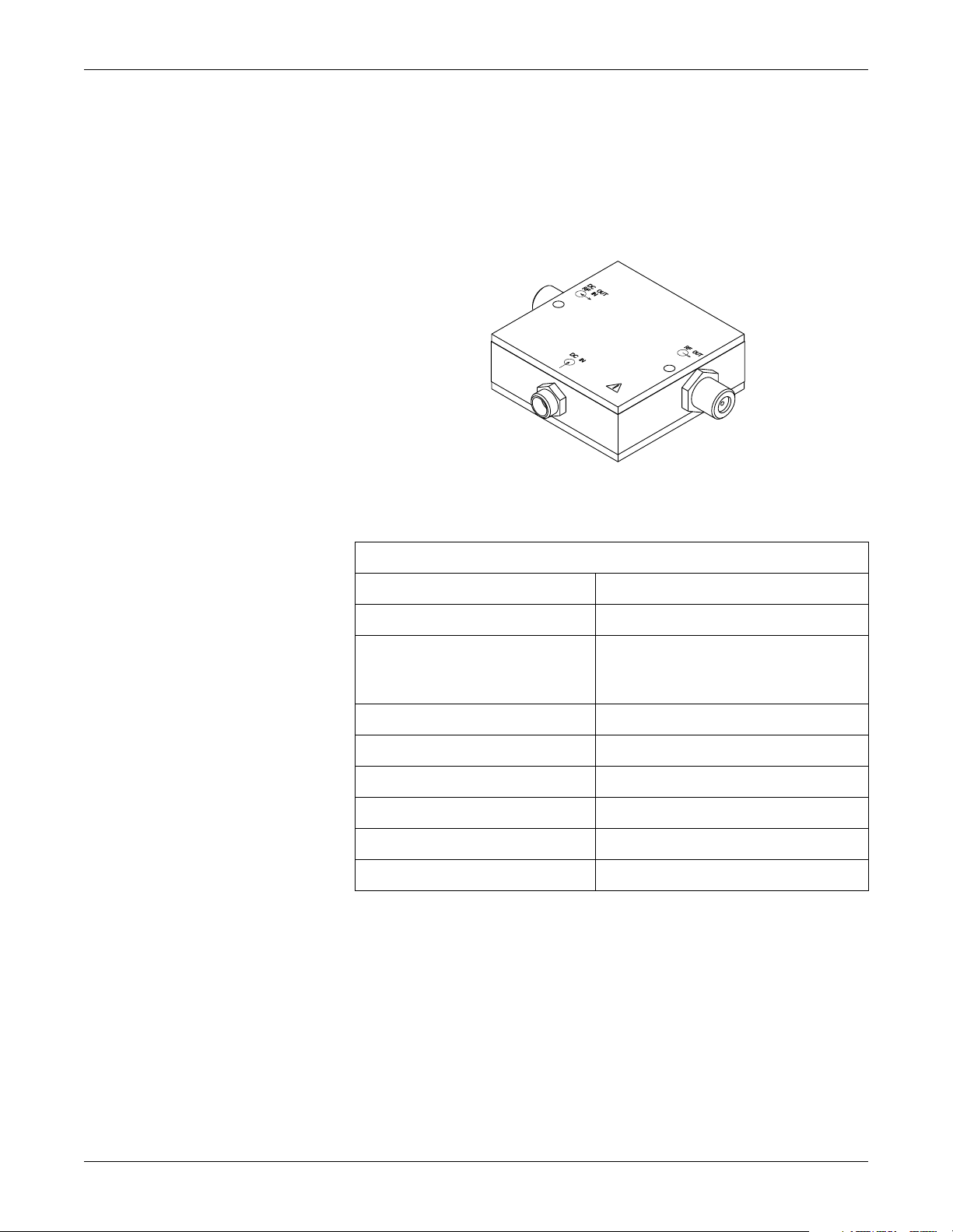
Parts Lists and Drawings: Bias Tee, PN 2001546-001
Bias Tee, PN 2001546-001
127(If using bias tee pn2001546-001 you must use GE Medical
Systems Information Technologies power supply pn422766-001.
Bias Tee Specifications
Frequency 400-650MHz
Insertion Loss 0.5dB, max
Isolation
DC OUT/RF IN port to DC IN port
RF OUT port to DC IN port
VSWR 1.3.1, max
DC Voltage 30 Volts, max
DC Current 1 Amp, max
RF Power +20dBm, max
Temperature 0 - 55° C
DC Resistance 0.1 ohms
20dB, min
Revision B ApexPro Telemetry System 7-7
2001989-024
Page 100

Parts Lists and Drawings: Antenna Amplifier, PN 2001727-00X
Antenna Amplifier, PN 2001727-00X
The antenna amplifier delivers 22dB of gain and draws 40mA of current.
Green LED on the side indicates that the amp is receiving power. DC
passing. Do not plug in backwards!
Description Part Number
U.S. Antenna Amplifier (560–614 MHz) 2001727-001
International Antenna Amplifier (420-474 MHz) 2001727-002
DC In/
RF Out
DC Out/
RF In
7-8 ApexPro Telemetry System Revision B
2001989-024
 Loading...