

Page 1
AP950PI
C
S
PIR Detector
Installation Instructions
Back housing
Front housing
Hinge tabs
U
LISTED
Cable entry knockout
Corner mounting knockout
Flat wall mounting
knockout
Note: This knockout
is not for use with the
AP950PI
Corner mounting knockout
Flat wall mounting knockout
Slot for opening tab
¤
L
U
10.0 ft.(3.0m) maximum
8.0 ft.(2.4m) typical
7.0 ft. (2.1m) minimum
8 ft. (2.4m)
25 ft. (7.6m)
35 ft. (10.7m)
35 ft. (10.7m)
LED
Window
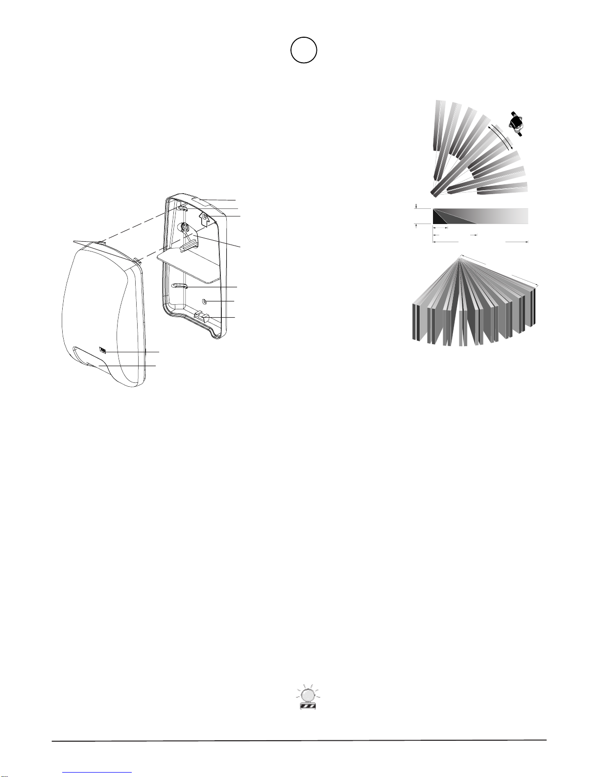
Figure 1. Exploded view
Description
The AP950PI is a passive infrared motion detector that is highly
sensitive to moving infrared sources. It features superior
immunity to RFI, vibration, static electricity, temperature
changes, and other false alarm sources.
The unit provides jumper-selectable sensitivity , mode, and LED
settings. The unit is designed to accept either the pet immune or
the standard mirror. The masks included allow the coverage
pattern to be modified for a wide variety of applications.
Parts
The following parts are included:
• PIR detector with pet immune mirror installed
• Standard mirror
• Two plastic masks
• Sheet of adhesive masking labels
• Cardboard undercrawl window mask
• One screw to secure the housings
Note
The maximum range is 35 feet (10.7m) with pet immune mirror
and Standard Sensitivity selected. The maximum range is 50
feet (15.2m) with standard mirror and Increased Sensitivity
selected. See Setting the Sensitivity, Mode, and LED.
Figure 2. Detection pattern
Selecting a Location
• The unit can be mounted from 7 to 10 feet (2.1 to 3.0m) high
except for pet alley application (see Pet Alley Application), but
for optimum detection and pet immunity, mount the unit
between 7 and 8 feet (2.1 and 2.4m) high.
• Mount the unit on a rigid vibration-free surface.
• Mount the unit so the expected movement of an intruder is
across the fields of the detection pattern. See Figure 2.
• Do not locate the unit on a surface exposed to moisture.
• Do not locate the unit where it may be exposed to false alarm
sources, such as:
- direct sunlight
- heat sources (heaters, radiators, etc.) in the field of view
- strong air drafts (fans, air conditioners, etc.) on unit
• Do not locate the unit where the ambient temperature is below
0° F (-18°C) or above 122°F (50°C).
• Do not aim the unit at windows or glass doors.
CAUTION
You must be free of static electricity before handling sensor
circuit boards. Touch a grounded, bare metal surface before
touching circuit boards or wear a grounding strap.
AP950PI PIR Detector AP950PI PIR Detector
AP950PI PIR Detector
AP950PI PIR Detector AP950PI PIR Detector
1
Page 2
2
1
21
(
Mounting and Wiring the Detector
1. Separate the front housing from the back housing by pressing in
on the opening tab at the bottom of the unit with a small, flatbladed screwdriver. See Figure 3.
2. Select and remove the appropriate corner or flat wall mounting
knockouts and the cable entry knockout on the back housing.
See Figure 1.
3. Strip the cable 2 inches (5cm) and pull it through the cable entry
knockout. Use screws and wall anchors, if necessary, to attach
the back housing to the wall. Do not overtighten.
4. Select the appropriate coverage pattern. See Selecting the
Coverage Pattern.
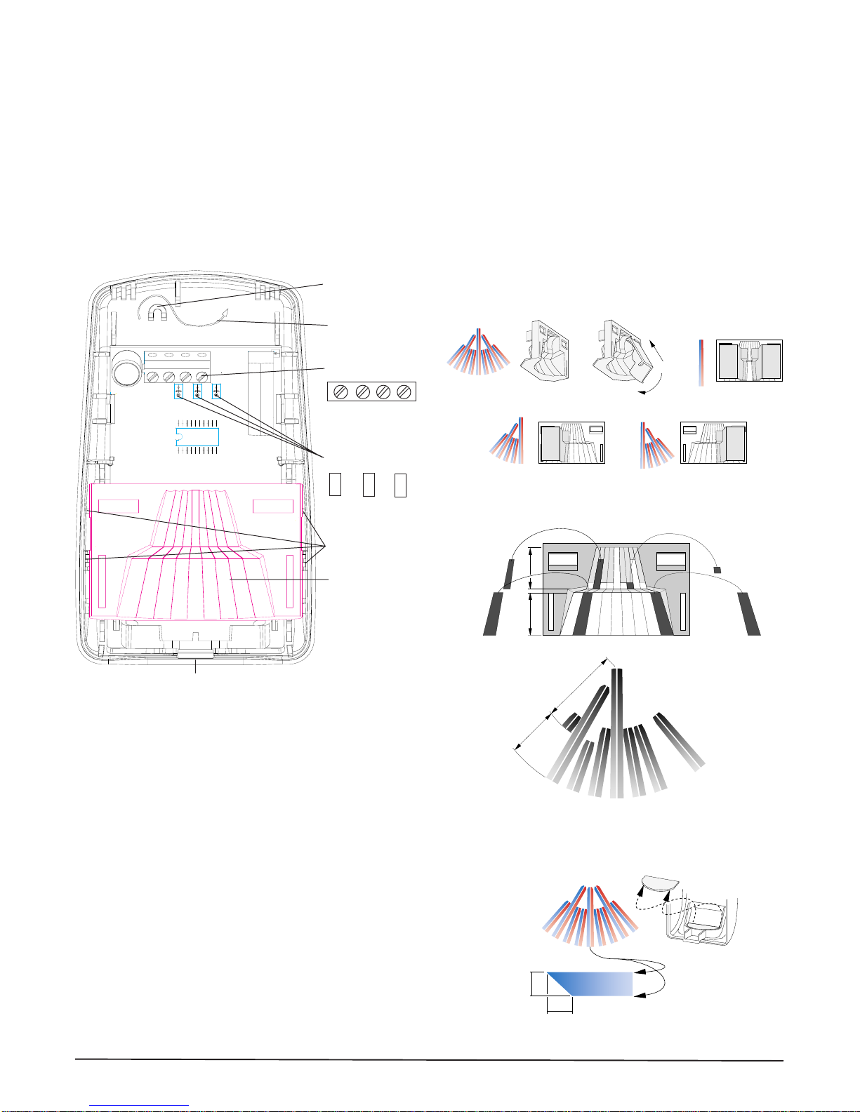
Cable strain relief
Wires
Terminal block
GND +12V NC COM
Jumpers:
SENS MODE LED
If necessary, use one or more of the following methods to modify the
coverage pattern:
• Use one or both of the plastic masks provided to mask off large
areas of coverage as shown in Figure 4.
• Mask the appropriate mirror curtains with the adhesive labels
provided. See the example shown in Figure 5. Do not use sharp
objects to remove unwanted labels. If necessary, carefully peel
the label off.
• Use the cardboard undercrawl window mask as shown in Figure
6. The undercrawl mask allows objects to be placed within 5 feet
(1.5m) of, or directly below, the unit.
After selecting the coverage pattern, snap the mirror back into the
front housing by pushing the mirror down into the mirror snaps (see
Figure 3). Then rotate the mirror down toward the front housing until
it snaps into position.
Figure 4. Plastic masks
Opening tab
Figure 3. Front housing interior
5. Set the sensitivity , mode, and LED jumpers for the application
desired. See Setting the Sensitivity, Mode, and LED.
6. Strip 1/4 inch (0.6cm) of insulation from each wire.
7. Insert each wire into the appropriate terminal and tighten
screws. Push the wires into the strain relief. See Figure 3.
8. T o close the unit, insert the hinge tabs at the top of the front
housing into the slots at the top of the back housing then swivel
the front housing toward the back housing to snap the unit
closed. See Figure 1.
9. Fasten the housings together with the screw provided.
Selecting the Coverage Pattern
The coverage pattern for the unit can be modified to fit specific
applications by masking off mirror curtains. Curtains should be
masked to avoid sources of false alarms, such as heaters, air
conditioners, and windows.
Remove the mirror by inserting a small screwdriver between the mirror
and the side of the front housing and gently prying the mirror out. Do
not pry from the end of the housing because the mirror may be
scratched. See Figure 3.
2
Mirror snaps
Mirror
A
19
2 34567 8
1
8
7
2 3456789
A
6
5
1
2
3
4
B
B
9
Figure 5. Adhesive labels
7.9 ft
2.4m)
5.0 ft
(1.5m)
Figure 6. Cardboard undercrawl window mask
AP950PI PIR Detector AP950PI PIR Detector
AP950PI PIR Detector
AP950PI PIR Detector AP950PI PIR Detector
Page 3

Setting the Sensitivity , Mode and
LED Jumpers
The unit provides three jumpers to set sensitivity, mode, and the LED.
See Figure 3.
Sensitivity
Standard Sensitivity (factory default) - Reduces
sensitivity and range for use with the pet immune mirror.
Range = 35 feet (10.7m). Both pins must be covered to place
the unit in Standard Sensitivity .
Increased Sensitivity - Increases sensitivity and range for
use with the standard mirror. Range = 50 feet (15.2m). Either
pin can be uncovered to place the unit in Increased
Sensitivity.
Mode
BI= Bi-Curtain Mode (factory default). Increases
false alarm immunity in smaller areas. Requires the intruder
to pass through two curtains to trigger an alarm. Do not use
for single curtain applications or ranges under 5 feet (1.5m).
Both pins must be covered to place the unit in Bi-Curtain
Mode.
STD= Standard Curtain Mode. Use for wide-angle or
single-curtain applications. Requires the intruder to only
pass through one curtain to trigger an alarm. Either pin can
be uncovered to place the unit in Standard Curtain Mode.
Note
Operation of the AP950PI in the Standard Curtain Mode is
UL 639 Listed for a range of 35 feet (10.7m) with both mirrors in
Standard Sensitivity, and for a range of 50 feet (15.2m) with the
standard mirror in Increased Sensitivity. For operation in BiCurtain Mode, the unit is UL 639 Listed for 30 feet (9.1m) range
only. For ranges from 30 to 50 feet (9.1 to 15.2m) with sensitivity
set to Increased and Bi-Curtain mode, the unit is not UL 639
Listed but will provide detection within 6 steps or 14 feet (4.3m)
across the plane of coverage. UL has not tested the 6 steps or 14
foot (4.3m) detection.
Pet Immunity
When mounted properly, the unit provides false alarm immunity to
dogs and similar animals. The size and body temperature of the
animal, which depends on the length of the animal's coat, affects the
immunity to false alarms. Dogs vary in body temperature by breed. A
very warm-blooded dog with short hair will not be as immune to false
alarms as a similar dog with long hair. Therefore, the acceptable short
hair dog is limited to a lighter weight dog. See the examples listed in
the following table:
Long hair Medium hair Short hair Not recommended,
(2" long) up (1.5" long) (1" long) up use pet alley
to 80 lbs. up to 50 lbs. to 30 lbs. application
Chow Chow Collie Welsh Corgi Doberman
Husky English Setter Border Terrier Great Dane
Standard Border Collie Cocker Spaniel Greyhound
Poodle (uncut)
Retriever Springer Spaniel French Bulldog Mastiff
Sheepdog Shetland Pug Pit Bull
Sheepdog
Shepherd Cats
Malamute
Note
To reduce false alarms, keep animals of f the furniture and
avoid aiming the unit at stairs.
Pet immunity not verified by UL.
Pet Alley Application
To create a detection-free area close to the floor, mount the unit 3.5
feet (1.1m) above the floor, upside down (detector window towards
the ceiling). Use the standard mirror and set the J2 jumper for
Increased Sensitivity (both pins cannot be covered). The cardboard
undercrawl window mask should be in place to reduce exposure to the
ceiling.
As shown in Figure 7, pets are free to roam below the mounting
height of the unit without causing alarms.
Note
Operation of the AP950PI in the S tandard Curtain Mode or in
the Bi-Curtain Mode is UL 639 Listed for the pet alley
application at a mounting height of no more than 3.5 feet (1.1m)
with a range of 30 feet (9.1m). For ranges greater than 30 feet
(9.1m) or mounting heights higher than 3.5 feet (1.1m), the unit
is not UL 639 Listed.
LED
T o enable the LED (factor y default), both pins
must be covered by the jumper .
T o disable the LED, either pin can be uncovered.
Note
The LED only lights if an alarm occurs and the jumper is
covering both pins.
AP950PI PIR Detector AP950PI PIR Detector
AP950PI PIR Detector
AP950PI PIR Detector AP950PI PIR Detector
3.5 ft.
(1.1m)
Figure 7. Pet Alley
3
Page 4

Operation Information
When the unit is powered up, the LED turns on and the relay
contacts open for about 12 seconds, then the LED goes off and the
relay contacts close. Thereafter, the LED will turn on and the relay
contacts will open every time an alarm occurs. The unit should be
allowed to settle for at least one minute after power-up before walk
testing. When walk testing, walk across the curtains, not directly
toward or away from the unit. Wait 10 seconds between trips to
allow the unit to stabilize.
Maintaining the Detector
When installed and used properly, the AP950PI provides many years
of service with minimal maintenance. T o ensure proper operation,
you should walk test the unit annually.
Clean the inside of the unit with a soft bristled brush or compressed
air. Clean the outside with a damp (water) cloth as needed to keep it
free of dust and dirt. Always test the unit after cleaning.
Dimensions
Specifications
Input voltage ............................................................. 8.2 to 15VDC
Input voltage (UL) ............................................... 9.7 to 13.6 VDC
Peak to peak ripple ........................................... 2V max at 12VDC
Current consumption ..................................................... 17mA max
Mounting height............................................ 7' to 10' (2.1m to 3m)
Relay contacts.................................................... 50 mA max at 28V
Relay type .................................................. Closed loop (Form A)
Alarm time (LED and relay) ...............................2.9 to 3.5 seconds
Operating temperature ....................... 0° to 122° F (-18° to 50° C)
Relative humidity.......................................... 93% non-condensing
RFI immunity ........................ - 20V/meter from 28 to 1000MHz
Weight .................................................................... 0.26 lbs (120 g)
Dimensions:
Width.................................................................... 2.9" (7.4 cm)
Depth .................................................................. .2.1" (5.2 cm)
Height ................................................................ 4.7" (12.0 cm)
Number of curtains ....................................................................... 9
View angle ................................................................................. 89°
Detection range ............................ 50' (15.2m) with standard mirror
and sensitivity set to Increased
35' (10.7m) with pet immune mirror
and sensitivity set to Standard
Listings ............................................................................. C-UL US
>
4.7"
12.0cm
2.9"
7.4cm
2.1"
5.2cm
Ordering Information
Model Number Description
AP950PI PIR, closed loop, Form A, 35 foot (10.7m) pet immune mirror installed, 50 foot (15.2m) st andard mirror
included
12345 SW Leveton Drive
Tualatin, OR 97062
www.interlogixsecurity.com
www.sentrol.com
© 2002 GE Interlogix, Inc.
4
Phone: 503-692-4052
USA & Canada: 800-547-2556
Technical Service: 800-648-7424
FaxBack: 800-483-2495
GE Interlogix
1037263 Rev B 06/02
AP950PI PIR Detector AP950PI PIR Detector
AP950PI PIR Detector
AP950PI PIR Detector AP950PI PIR Detector
 Loading...